WO2021186680A1 - エレベーターの制御装置 - Google Patents
エレベーターの制御装置 Download PDFInfo
- Publication number
- WO2021186680A1 WO2021186680A1 PCT/JP2020/012351 JP2020012351W WO2021186680A1 WO 2021186680 A1 WO2021186680 A1 WO 2021186680A1 JP 2020012351 W JP2020012351 W JP 2020012351W WO 2021186680 A1 WO2021186680 A1 WO 2021186680A1
- Authority
- WO
- WIPO (PCT)
- Prior art keywords
- speed
- car
- brake
- command
- control device
- Prior art date
- Legal status (The legal status is an assumption and is not a legal conclusion. Google has not performed a legal analysis and makes no representation as to the accuracy of the status listed.)
- Ceased
Links
Images






Classifications
-
- B—PERFORMING OPERATIONS; TRANSPORTING
- B66—HOISTING; LIFTING; HAULING
- B66B—ELEVATORS; ESCALATORS OR MOVING WALKWAYS
- B66B1/00—Control systems of elevators in general
- B66B1/24—Control systems with regulation, i.e. with retroactive action, for influencing travelling speed, acceleration, or deceleration
- B66B1/28—Control systems with regulation, i.e. with retroactive action, for influencing travelling speed, acceleration, or deceleration electrical
- B66B1/32—Control systems with regulation, i.e. with retroactive action, for influencing travelling speed, acceleration, or deceleration electrical effective on braking devices, e.g. acting on electrically controlled brakes
Definitions
- This disclosure relates to an elevator control device.
- Patent Document 1 discloses an elevator.
- the brake 2 applies braking torque to the hoisting machine to control the rotation of the hoisting machine.
- An object of the present disclosure is to provide an elevator control device capable of suppressing the vibration of a car in speed control using a brake 2.
- the elevator control device is an elevator system that controls the ascent and descent of the car by the brake 2 in the hoisting machine.
- a speed detection unit for outputting and a speed control unit for determining the current command of the brake 2 based on the product of the deviation between the speed command and the detected speed and the absolute value of the deviation are provided.
- the control device determines the current command of the brake 2 based on the product of the deviation between the speed command and the detected speed and the absolute value of the deviation. Therefore, the vibration of the car can be suppressed in the speed control using the brake 2.
- FIG. 5 is a configuration diagram of an elevator system to which the elevator control device according to the first embodiment is applied.
- FIG. 5 is a configuration diagram of a brake of an elevator system to which an elevator control device according to the first embodiment is applied. It is a figure which shows the relationship between the braking current and the braking force of the brake of the elevator system to which the elevator control device in Embodiment 1 is applied. It is a figure which shows the result of the speed control by the brake of the elevator system to which the elevator control device in Embodiment 1 is applied. It is a figure which shows the control result by the control device of the elevator in Embodiment 1.
- FIG. It is a hardware block diagram of the control device of the elevator in Embodiment 1.
- FIG. 5 is a configuration diagram of an elevator system to which the elevator control device according to the second embodiment is applied. It is a figure which shows the control result by the control device of the elevator in Embodiment 2.
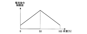
- FIG. It is a figure which shows the limit value of the current command by the control device of an elevator in Embodiment 3.
- FIG. It is a figure which shows the limit value of the acceleration by the control device of the elevator in Embodiment 4.
- FIG. It is a figure which shows the speed limit value by the control device of the elevator in Embodiment 4.
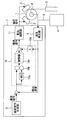
- FIG. 1 is a configuration diagram of an elevator system to which the elevator control device according to the first embodiment is applied.
- the hoisting machine 1 is provided in a machine room (not shown) or a hoistway (not shown).
- the pair of brakes 2 are provided on the outside of the hoisting machine 1.
- the main rope 3 is wound around the hoisting machine 1.
- the car 4 is provided inside the hoistway.
- the basket 4 is hung on one side of the main rope 3.
- the balance weight 5 is provided inside the hoistway.
- the balance weight 5 is hung on the other side of the main rope 3. That is, the car 4 and the counterweight 5 are connected by the main rope 3 in a slidable manner via the hoisting machine 1.
- the car 4 and the counterweight 5 move up and down by the rotation of the hoisting machine 1.
- the weight of the balanced weight 5 is often set so that the cage 4 and the balanced weight 5 are balanced when a load of 50% of the rated load capacity acts on the car 4.
- the weight of the counterweight 5 may be set so that the car 4 and the counterweight 5 are balanced when a load of 40% or 45% of the rated load capacity acts on the car 4.
- a weight imbalance between the basket 4 and the balancing weight 5 occurs except when the weight of the basket 4 and the weight of the balancing weight 5 are exactly the same. At this time, an unbalanced torque due to the weight difference acts on the hoisting machine 1. At this time, when the brake 2 is released, the car 4 moves up and down due to the unbalanced torque even if the hoisting machine 1 does not generate the torque for driving the car 4.
- the position detector 6 is provided on the hoisting machine 1.
- the position detector 6 is an optical encoder, a resolver, a magnetic sensor, or the like.
- the position detector 6 detects the rotation angle of the hoisting machine 1.
- the detected rotation angle is used for speed control and position control of the hoist 1.
- the rotation angle detected by the position detector 6 is used to determine the command signal of the brake 2.
- the control device 7 is provided in the machine room or the hoistway.
- the control device 7 includes a speed detection unit 8, a speed command generation unit 9, a speed control unit 10, and a current control unit 11.
- the speed detection unit 8 calculates the rotation speed of the hoisting machine 1 using the rotation angle of the hoisting machine 1 detected by the position detector 6. For example, the speed detection unit 8 calculates the rotation speed by the time derivative of the rotation angle. For example, the speed detection unit 8 smoothes the rotation speed by using a low-pass filter in order to remove noise due to time differentiation. For example, the speed detection unit 8 calculates the rotation speed at predetermined fixed time intervals. For example, the speed detection unit 8 calculates the rotation speed for each preset constant rotation angle after providing a configuration for measuring the time.
- the speed command generation unit 9 generates a rotation speed command of the hoisting machine 1 for guiding the car 4 to the target floor. For example, the speed command generation unit 9 generates a rotation speed command as an output of position control after including the position control system of the hoisting machine 1.
- the speed control unit 10 includes an absolute value calculator 10a, a multiplier 10b, and a controller 10c.
- the absolute value calculator 10a calculates the absolute value of the speed deviation, which is the difference between the speed command output of the speed command generation unit 9 and the detection speed output of the speed detection unit 8.
- the multiplier 10b multiplies the velocity deviation by the absolute value of the velocity deviation calculated by the absolute value calculation unit.
- the controller 10c calculates the current command of the brake 2 using the multiplication result of the speed deviation and its absolute value.
- Various control methods are used as the control method of the controller 10c. For example, as the control method of the controller 10c, any one of P control, PI control, and PID control is used.
- the current control unit 11 calculates the voltage command to the brake 2 by using the current command which is the output of the speed control unit 10 in various ways. For example, the current control unit 11 detects the current of the brake 2 and then generates a voltage command using the current command that is the output of the speed control unit 10.
- FIG. 2 is a configuration diagram of a brake of an elevator system to which the elevator control device according to the first embodiment is applied.
- the brake drum 12 is provided on a hoisting machine 1 (not shown in FIG. 2).
- the brake drum 12 serves as a braking surface of the brake 2.
- the brake 2 generates a braking torque that brakes the brake drum 12. As a result, the rotation of the hoisting machine 1 is braked by the brake 2.
- the brake 2 includes a brake shoe 13, a pressing spring 14, and an electromagnetic coil 15.
- the brake shoe 13 faces the brake drum 12.
- the pressing spring 14 generates a spring force that presses the brake shoe 13 against the brake drum 12.
- the electromagnetic coil 15 generates an attractive force in the direction in which the brake shoe 13 is separated from the brake drum 12.
- the value of the braking force of the brake 2 at this time is a value obtained by subtracting the suction force from the spring force.
- the attractive force becomes larger than the spring force.
- the brake shoe 13 separates from the brake drum 12. In this state, the braking force on the brake drum 12 does not act.
- the brake shoe 13 When the brake shoe 13 is open, the suction force is larger than the spring force for a while even if the current flowing through the electromagnetic coil 15 becomes small. Therefore, the brake shoe 13 does not move. When the value of the current becomes smaller than a certain value, the attractive force becomes smaller than the spring force. As a result, the brake shoe 13 falls so as to be pressed against the brake drum 12. As a result, the braking force on the brake drum 12 acts.
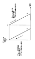
- FIG. 3 is a diagram showing the relationship between the braking current and the braking force of the brake of the elevator system to which the elevator control device according to the first embodiment is applied.
- the horizontal axis of FIG. 3 shows the current flowing through the electromagnetic coil 15.
- the vertical axis of FIG. 3 shows the braking force of the brake 2.
- the braking force of the brake 2 does not change until the value of the current becomes A.
- the braking force of the brake 2 decreases.
- the value of the current becomes B or more, the braking force of the brake 2 becomes 0.
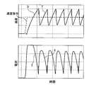
- FIG. 4 is a diagram showing the result of speed control by the brake 2 of the elevator system to which the elevator control device according to the first embodiment is applied.
- FIG. 4 shows a control result when the output of the absolute value calculator 10a of FIG. 1 is 1.
- the control result is a control result when the speed control unit 10 is composed of only the controller 10c.
- the upper part of FIG. 4 shows the speed of the car 4.
- the lower part of FIG. 4 shows the current of the brake 2.
- the control device 7 increases the current of the brake 2. At this time, the brake 2 is sucked. Even if the braking force with respect to the brake drum 12 becomes 0, the acceleration of the car 4 is gradual.
- the car 4 accelerates so as to approach the speed command.
- the control device 7 drops the brake 2 to reduce the current of the brake 2 so that the unbalance torque becomes small.
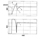
- FIG. 5 is a diagram showing a control result by the elevator control device in the first embodiment.
- the control device 7 increases the current of the brake 2. At this time, the brake 2 is sucked. Even if the braking force with respect to the brake drum 12 becomes 0, the acceleration of the car 4 is gradual.
- the car 4 accelerates so as to approach the speed command.
- the control device 7 drops the brake 2 to reduce the current of the brake 2 so that the unbalance torque becomes small.
- the absolute value of the velocity deviation is smaller than that at the time of the first acceleration. Therefore, the responsiveness of the controller 10c is low. As a result, the brake 2 is not sucked until the braking force with respect to the brake drum 12 becomes zero. In this case, the car 4 slowly re-accelerates. As a result, as shown by K in FIG. 5, the actual speed follows the speed command.
- the brake 2 is completely sucked. As a result, the braking force with respect to the brake drum 12 becomes zero. In this state, the car 4 accelerates. Therefore, the braking force with respect to the brake drum 12 becomes discontinuous due to the influence of hysteresis, but after that, the response of the speed of the car 4 does not become a sawtooth wave.
- the control device 7 calculates the current command of the brake 2 based on the product of the speed deviation between the speed command and the detected speed and the absolute value of the speed deviation.
- the absolute value of the speed deviation is equal to making the control gain of the controller 10c variable. Therefore, the responsiveness of the entire control system can be automatically changed according to the deviation between the speed command and the detection speed. For example, if the deviation between the speed command and the detection speed is large, the gain of the controller 10c becomes large, and the responsiveness can be improved. For example, if the deviation between the speed command and the detection speed is small, the gain of the controller 10c becomes small, and the responsiveness can be lowered.
- the hysteresis characteristic of the brake 2 is taken into consideration. Therefore, the vibration of the car 4 can be suppressed regardless of the load of the car 4. As a result, the car 4 can be operated without causing discomfort to the user.
- the car 4 can be moved by using the imbalance between the car 4 and the balance weight 5 and repeatedly dropping and sucking the brake 2 as in the bang-bang control.
- the pair of brakes 2 at that time The control results are different from each other. Therefore, the speed of the car 4 cannot be controlled in the same manner as in the present embodiment.
- feedback control is performed by observing the speed change of the car 4. Therefore, it is possible to provide more robust control against the influence of individual differences and temperature fluctuations of each of the pair of brakes 2.
- FIG. 6 is a hardware configuration diagram of the elevator control device according to the first embodiment.
- Each function of the control device 7 can be realized by a processing circuit.
- the processing circuit includes at least one processor 100a and at least one memory 100b.
- the processing circuit includes at least one dedicated hardware 200.
- each function of the control device 7 is realized by software, firmware, or a combination of software and firmware. At least one of the software and firmware is written as a program. At least one of the software and firmware is stored in at least one memory 100b. At least one processor 100a realizes each function of the control device 7 by reading and executing a program stored in at least one memory 100b. At least one processor 100a is also referred to as a central processing unit, a processing unit, an arithmetic unit, a microprocessor, a microcomputer, and a DSP.
- at least one memory 100b is a non-volatile or volatile semiconductor memory such as RAM, ROM, flash memory, EPROM, EEPROM, magnetic disk, flexible disk, optical disk, compact disk, mini disk, DVD, or the like.
- the processing circuit includes at least one dedicated hardware 200
- the processing circuit is realized by, for example, a single circuit, a composite circuit, a programmed processor, a parallel programmed processor, an ASIC, an FPGA, or a combination thereof.
- NS each function of the control device 7 is realized by a processing circuit.
- each function of the control device 7 is collectively realized by a processing circuit.
- a part may be realized by the dedicated hardware 200, and the other part may be realized by software or firmware.
- the function of the speed control unit 10 is realized by a processing circuit as dedicated hardware 200, and the function other than the function of the speed control unit 10 is a program in which at least one processor 100a is stored in at least one memory 100b. It may be realized by reading and executing.
- the processing circuit realizes each function of the control device 7 by hardware 200, software, firmware, or a combination thereof.
- FIG. 7 is a configuration diagram of an elevator system to which the elevator control device according to the second embodiment is applied.
- the same or corresponding parts as those of the first embodiment are designated by the same reference numerals. The explanation of the relevant part is omitted.
- the control device 7 of the second embodiment is a device in which a feedback loop proportional to the speed is added to the speed control unit 10 with respect to the control device 7 of the first embodiment.
- the speed proportional feedback gain 10d multiplies the detection speed, which is the output of the speed detection unit 8, by the speed proportional gain K.
- the speed control unit 10 calculates the current command by subtracting the output of the speed proportional feedback gain 10d from the output of the controller 10c.
- the controller 10c When the speed of the car 4 is slow, the deviation between the speed command and the detection speed is large. Therefore, the controller 10c generates a large current command. At this time, the brake 2 is completely sucked. As a result, the braking force with respect to the brake drum 12 becomes zero. At this time, the car 4 accelerates.
- the controller 10c tries to generate a braking force on the brake drum 12 by reducing the current command.
- the brake 2 does not fall immediately due to the influence of hysteresis. Therefore, an overshoot occurs.
- the output of the speed proportional feedback gain 10d also increases. Therefore, the current command becomes small before a large overshoot occurs.
- the timing at which the brake 2 falls is earlier than when the speed proportional feedback gain 10d is not provided.
- the overshoot becomes smaller than when there is no speed proportional feedback gain 10d.
- the speed proportional feedback gain 10d is a term proportional to the speed. Therefore, the velocity proportional feedback gain 10d changes the damping coefficient of the entire control system. The faster the speed of the car 4, the higher the damping coefficient of the control system.
- under-damping an overshoot occurs for the command.
- critical attenuation no overshoot occurs for the command.
- over-attenuation the response is slower than critical attenuation without overshooting the command.
- the velocity proportional feedback gain 10d is set so that the damped vibration becomes critical damping or overdamping. As a result, the overshoot is small.
- FIG. 8 is a diagram showing a control result by the elevator control device according to the second embodiment.
- the speed proportional feedback gain 10d increases the attenuation in the control system. Therefore, the overshoot of the first acceleration of the car 4 is suppressed as compared with the response shown in FIG.
- the control device 7 increases the damping to cause an overshoot. Shave. Therefore, the vibration of the car 4 can be suppressed more reliably regardless of the load of the car 4. As a result, the car 4 can be operated without causing discomfort to the user.
- FIG. 9 is a diagram showing a limit value of a current command by the elevator control device according to the third embodiment.
- the same or corresponding parts as those of the first embodiment are designated by the same reference numerals. The explanation of the relevant part is omitted.
- the speed control unit 10 calculates the current command of the brake 2 according to the speed deviation.
- the speed deviation between the speed command and the detected speed is large, the current command of the brake 2 also becomes large.
- the current value increases, the brake 2 is completely sucked. As a result, the braking force with respect to the brake drum 12 becomes zero.
- the state of the brake 2 does not change even if the current becomes larger. Therefore, even if an excessive current flows through the brake 2, not only the control performance of the brake 2 does not change, but also the brake 2 may break down. Therefore, in the third embodiment, the current command is limited.
- the horizontal axis in FIG. 9 is the load of the car 4.
- the vertical axis of FIG. 9 is the limit value of the current command.
- the current value may be smaller as the load of the car 4 goes from 50% to 0%.
- the current value may be smaller as the load of the cage 4 goes from 50% to 100%.
- the weight of the counterweight 5 is set so that the cage 4 and the counterweight 5 are balanced when 40% of the rated load capacity is in the car 4, the load of the car 4 is 40. When%, the unbalanced torque is minimized.
- the limit value of the current command shown in FIG. 9 can be considered.
- a weight 5 having a known weight is loaded on the car 4, the current of the brake 2 is gradually increased, and the position detector 6 detects that the car 4 has started to move.
- the information on the current value at that time and the information on the weight of the weight 5 may be stored in association with each other.
- the limit value of the current command of the brake 2 can be determined with respect to the load of the car 4.
- the stored current value is a current value when the speed calculated from the position detector 6 exceeds a preset value.
- the stored current value is a current value when the acceleration calculated from the position detector 6 exceeds a preset value.
- the load of the car 4 may be detected by using a weighing device, the current value corresponding to the load may be called as the limit value of the current command, and the current command may be limited. ..
- the control device 7 limits the current command. Therefore, it is possible to prevent the current command from becoming a current equal to or higher than B in FIG. As a result, the discontinuity between the suction and the drop of the brake 2 can be reduced.
- FIG. 10 is a diagram showing a limit value of acceleration by the elevator control device according to the fourth embodiment.
- FIG. 11 is a diagram showing a speed limit value by the elevator control device according to the fourth embodiment.
- the same or corresponding parts as those of the first embodiment are designated by the same reference numerals. The explanation of the relevant part is omitted.
- the speed control unit 10 calculates the current command of the brake 2 according to the speed deviation.
- the speed deviation between the speed command and the detected speed is large, the current command of the brake 2 also becomes large. Unless the speed deviation between the speed command and the detected speed becomes large, the current command does not become large.
- the magnitudes of the acceleration and the speed of the speed command are limited.
- the horizontal axis of FIG. 10 is the load of the car 4.
- the vertical axis of FIG. 10 shows the limit value of the acceleration of the speed command.
- the load of the car 4 is 100%, it indicates that the user with the rated load capacity is in the car 4.
- the acceleration of the speed command may be larger.
- the acceleration of the speed command may be smaller.
- the weight of the counterweight 5 is set so that the cage 4 and the counterweight 5 are balanced when 40% of the rated load capacity is in the car 4, the load of the car 4 is 40. When%, the unbalanced torque is minimized.
- Various methods for setting the acceleration of the speed command shown in FIG. 10 can be considered. For example, when installing an elevator, a weight 5 having a known weight is loaded on the car 4, the current of the brake 2 is gradually increased, and the position detector 6 detects that the car 4 has started to move. The acceleration information at that time and the weight information of the weight 5 may be stored in association with each other. As a result, the limit value of the acceleration of the speed command can be determined with respect to the load of the car 4. When the stored acceleration is actually used, the load of the car 4 may be detected by using a weighing device, the acceleration corresponding to the load may be called as the acceleration limit value of the speed command, and the speed command may be limited. ..
- the horizontal axis of FIG. 10 is the weight of the basket 4.
- the vertical axis of FIG. 10 shows the limit value of the speed command.
- the speed command may be increased as the load on the car 4 approaches 0% or 100%.
- the load of the car 4 may be detected by using a weighing device, the limit value of the speed command corresponding to the load may be called, and the speed command may be limited.
- the acceleration of the speed command and the magnitude of the speed command are limited. Therefore, it is possible to prevent the current command from becoming a value equal to or higher than B in FIG. As a result, the discontinuity between the suction and the drop of the brake 2 can be reduced.
- the two-to-one roping method or another roping method may be used.
- the number of brakes 2 may be changed from the first embodiment to the fourth embodiment.
- the position detector 6 may be provided in the car 4.
- the movement amount of the car 4 may be detected and the movement amount may be used to determine the command signal of the brake 2.
- the position detector 6 may be used as an absolute position sensor. Specifically, the movement of the car 4 may be detected by providing a magnetic tape, an ID tape, or the like on the hoistway side and providing a reading unit in the car 4. In this case as well, the movement amount of the car 4 may be detected and the movement amount may be used to determine the command signal of the brake 2.
- the elevator control device of the present disclosure can be used for the elevator system.
Landscapes
- Engineering & Computer Science (AREA)
- Automation & Control Theory (AREA)
- Elevator Control (AREA)
- Cage And Drive Apparatuses For Elevators (AREA)
Abstract
ブレーキを用いた速度制御においてかごの振動を抑制することができるエレベーターの制御装置を提供する。エレベーターの制御装置は、巻上機においてブレーキによりかごの昇降を制御するエレベーターシステムにおいて、前記かごの速度指令を出力する速度指令生成部と、前記かごの速度の検出速度を出力する速度検出部と、前記速度指令と前記検出速度との偏差と当該偏差の絶対値との積に基づいて前記ブレーキの電流指令を決定する速度制御部と、を備えた。
Description
本開示は、エレベーターの制御装置に関する。
特許文献1は、エレベーターを開示する。当該エレベーターにおいて、ブレーキ2は、巻上機に制動トルクを与えて巻上機の回転を制御する。
しかしながら、特許文献1に記載のエレベーターは、ブレーキ2の吸引と落下とで生じるヒステリシスを考慮しない。このため、かごが振動する。
本開示は、上述の課題を解決するためになされた。本開示の目的は、ブレーキ2を用いた速度制御においてかごの振動を抑制することができるエレベーターの制御装置を提供することである。
本開示に係るエレベーターの制御装置は、巻上機においてブレーキ2によりかごの昇降を制御するエレベーターシステムにおいて、前記かごの速度指令を出力する速度指令生成部9と、前記かごの速度の検出速度を出力する速度検出部と、前記速度指令と前記検出速度との偏差と当該偏差の絶対値との積に基づいて前記ブレーキ2の電流指令を決定する速度制御部と、を備えた。
本開示によれば、制御装置は、速度指令と検出速度との偏差と当該偏差の絶対値との積に基づいてブレーキ2の電流指令を決定する。このため、ブレーキ2を用いた速度制御においてかごの振動を抑制することができる。
実施の形態について添付の図面に従って説明する。なお、各図中、同一または相当する部分には同一の符号が付される。当該部分の重複説明は適宜に簡略化ないし省略する。
実施の形態1.
図1は実施の形態1におけるエレベーターの制御装置が適用されるエレベーターシステムの構成図である。
図1は実施の形態1におけるエレベーターの制御装置が適用されるエレベーターシステムの構成図である。
図1のエレベーターシステムにおいて、巻上機1は、図示されない機械室または図示されない昇降路に設けられる。一対のブレーキ2は、巻上機1の外側に設けられる。主ロープ3は、巻上機1に巻き掛けられる。
かご4は、昇降路の内部に設けられる。かご4は、主ロープ3の一側に吊るされる。釣合おもり5は、昇降路の内部に設けられる。釣合おもり5は、主ロープ3の他側に吊るされる。すなわち、かご4と釣合おもり5とは、主ロープ3により巻上機1を介してつるべ式に接続される。かご4と釣合おもり5とは、巻上機1の回転により昇降運動する。
なお、釣合おもり5の重量は、定格積載量の50%の荷重がかご4に作用したときにかご4と釣合おもり5が釣り合うように設定されることが多い。釣合おもり5の重量は、定格積載量の40%または45%の荷重がかご4に作用したときにかご4と釣合おもり5が釣り合うように設定されてもよい。
かご4の重量と釣合おもり5との重量が完全に一致するとき以外において、かご4と釣合おもり5との重量アンバランスが生じる。この際、重量差によるアンバランストルクが巻上機1に作用する。このとき、ブレーキ2が開放されると、巻上機1がかご4を駆動するトルクを発生させなくても、かご4は、アンバランストルクにより昇降運動する。
位置検出器6は、巻上機1に設けられる。例えば、位置検出器6は、光学式エンコーダ、レゾルバ、磁気センサ等である。位置検出器6は、巻上機1の回転角度を検出する。検出された回転角度は、巻上機1の速度制御と位置制御とに使用される。位置検出器6で検出された回転角度は、ブレーキ2の指令信号を決定するために使用される。
制御装置7は、機械室または昇降路に設けられる。制御装置7は、速度検出部8と速度指令生成部9と速度制御部10と電流制御部11とを備える。
速度検出部8は、位置検出器6により検出された巻上機1の回転角度を用いて、巻上機1の回転速度を演算する。例えば、速度検出部8は、回転角度の時間微分によって、回転速度を演算する。例えば、速度検出部8は、時間微分によるノイズを除去するためにローパスフィルタを用いて回転速度を平滑化する。例えば、速度検出部8は、予め設定された一定時間ごとに回転速度を演算する。例えば、速度検出部8は、時間を計測するための構成を備えたうえで予め設定された一定回転角ごとに回転速度を演算する。
速度指令生成部9は、かご4を目的の階床へ案内するための巻上機1の回転速度指令を生成する。例えば、速度指令生成部9は、巻上機1の位置制御系を含んだうえで位置制御の出力として回転速度指令を生成する。
速度制御部10は、絶対値演算器10aと乗算器10bと制御器10cとを備える。絶対値演算器10aは、速度指令生成部9の出力である速度指令と速度検出部8の出力である検出速度の差分である速度偏差の絶対値を演算する。乗算器10bは、速度偏差と絶対値演算部で演算された速度偏差の絶対値を乗算する。制御器10cは、速度偏差とその絶対値の乗算結果を用いてブレーキ2の電流指令を演算する。制御器10cの制御方式として、種々の制御方式が用いられる。例えば、制御器10cの制御方式として、P制御とPI制御とPID制御とのうちのいずれかの制御方式が用いられる。
電流制御部11は、様々な方法で速度制御部10の出力である電流指令を用いてブレーキ2への電圧指令を演算する。例えば、電流制御部11は、ブレーキ2の電流を検出したうえで速度制御部10の出力である電流指令を用いて電圧指令を生成する。
次に、図2を用いて、ブレーキ2を説明する。
図2は実施の形態1におけるエレベーターの制御装置が適用されるエレベーターシステムのブレーキの構成図である。
図2は実施の形態1におけるエレベーターの制御装置が適用されるエレベーターシステムのブレーキの構成図である。
図2において、ブレーキドラム12は、図2においては図示されない巻上機1に設けられる。ブレーキドラム12は、ブレーキ2の制動面となる。
ブレーキ2は、ブレーキドラム12を制動する制動トルクを発生させる。その結果、巻上機1の回転は、ブレーキ2により制動される。
具体的には、ブレーキ2は、ブレーキシュー13と押付バネ14と電磁コイル15とを備える。
ブレーキシュー13は、ブレーキドラム12に対向する。押付バネ14は、ブレーキシュー13をブレーキドラム12へ押し付けるバネ力を発生させる。電磁コイル15は、ブレーキシュー13をブレーキドラム12から離す方向へ吸引力を発生させる。
電流が電磁コイル15に流れていない際、電磁コイル15の吸引力は発生しない。このため、ブレーキシュー13は、押付バネ14のバネ力によってブレーキドラム12へ押し付けられる。その結果、ブレーキドラム12に対する制動力が作用する。
電流が電磁コイル15に流れている際、当該電流の大きさによって吸引力が変化する。この際のブレーキ2の制動力の値は、バネ力から吸引力を差し引いた値となる。当該電流の値がある値まで大きくなると、吸引力は、バネ力よりも大きくなる。その結果、ブレーキシュー13は、ブレーキドラム12から離れる。この状態において、ブレーキドラム12に対する制動力は作用しない。
ブレーキシュー13の開放時においては、電磁コイル15に流れる電流が小さくなっても、しばらくの間、吸引力は、バネ力よりも大きい。このため、ブレーキシュー13は、移動しない。当該電流の値がある値まで小さくなると、吸引力がバネ力よりも小さくなる。その結果、ブレーキシュー13は、ブレーキドラム12に押し付けられるように落下する。その結果、ブレーキドラム12に対する制動力は作用する。
次に、図3を用いて、ブレーキ2の電流と制動力との関係を説明する。
図3は実施の形態1におけるエレベーターの制御装置が適用されるエレベーターシステムのブレーキの電流と制動力との関係を示す図である。図3の横軸は電磁コイル15に流れる電流を示す。図3の縦軸はブレーキ2の制動力を示す。
図3は実施の形態1におけるエレベーターの制御装置が適用されるエレベーターシステムのブレーキの電流と制動力との関係を示す図である。図3の横軸は電磁コイル15に流れる電流を示す。図3の縦軸はブレーキ2の制動力を示す。
図3に示されるように、ブレーキ2の電流と制動力との関係において、吸引と落下とでヒステリシスを有する。
ブレーキ2の吸引時においては、電流が電磁コイル15に流れると、電流の値がAになるまで、ブレーキ2の制動力は変化しない。電流の値がAよりも大きくなると、ブレーキ2の制動力は減少する。電流の値がB以上になると、ブレーキ2の制動力は、0になる。
ブレーキ2の落下時においては、電流の値がCよりも大きいとき、ブレーキシュー13は、落下しない。この際、制動力は、0である。電流の値がCよりも小さくなると、ブレーキシュー13は落下する。その結果、ブレーキドラム12に対する制動力が作用する。
図3に示されるようなヒステリシスを有するブレーキ2の制動力により巻上機1の回転が制御される場合、ブレーキ2が吸引され始めると、電流の値はAよりも大きくなる。電流の値がBに達するまでの範囲において、制動力は、ヒステリシスの影響を受けずに電流に比例して調整される。このため、ブレーキドラム12に対する制動力は、連速的に制御される。
電流の値はBよりも大きくなると、ブレーキドラム12に対する制動力は、ヒステリシスの影響を受ける。このため、ブレーキドラム12に対する制動力は、連続的に制御されない。
例えば、かご4と釣合おもり5との重量の差が小さい場合、巻上機1に作用する荷重アンバランスによりトルクが小さくなる。この際、ブレーキ2が開放されると、巻上機1は、緩やかにしか加速されない。このため、実際の速度と速度指令との差が大きくなる。その結果、ブレーキ2の電流指令が大きくなる。この場合、電流の値はBとなる。次に、巻上機1が加速して速度偏差が小さくなった際にブレーキ2が落下しようとしても、制動力は、電流の値がCになるまでヒステリシスの影響を受けて落下しない。このため、ブレーキドラム12に対する制動力は、連続的に制御されない。
次に、図4を用いて、速度制御部10が制御器10cのみで構成された場合の制御結果を説明する。
図4は実施の形態1におけるエレベーターの制御装置が適用されるエレベーターシステムのブレーキ2による速度制御の結果を示す図である。
図4は実施の形態1におけるエレベーターの制御装置が適用されるエレベーターシステムのブレーキ2による速度制御の結果を示す図である。
図4は、図1の絶対値演算器10aの出力が1の場合の制御結果を示す。当該制御結果は、速度制御部10が制御器10cのみで構成された場合の制御結果となる。図4の上段は、かご4の速度を示す。図4の下段は、ブレーキ2の電流を示す。
かご4と釣合おもり5との重量の差が小さい場合、制御装置7は、ブレーキ2の電流を大きくする。この際、ブレーキ2は、吸引される。ブレーキドラム12に対する制動力が0となっても、かご4の加速は緩やかである。
この際、かご4は、速度指令に近づくように加速していく。かご4の速度偏差が小さくなったところで、制御装置7は、ブレーキ2を落下させてアンバランストルクが小さくなるようにブレーキ2の電流を減少させる。
しかしながら、ブレーキ2は、ヒステリシスの影響で落下しない。この場合、図4のDに示されるように、かご4の速度において、オーバーシュートが発生する。
図4のEに示されるように、ブレーキ2の電流が減少すると、ある電流でブレーキ2が落下する。この際、かご4の速度が急激に減少する。このとき、実際の速度が速度指令よりも小さくなると、かご4を再度加速する。このため、制御装置7は、ブレーキ2の電流を大きくすることで、ブレーキ2を吸引させる。実際の速度と速度指令との偏差が小さくなったところで、制御装置7は、ブレーキ2の電流を減少させる。
しかしながら、ブレーキ2は、ヒステリシスの影響で落下しない。この場合、図4のFに示されるように、かご4の速度において、オーバーシュートが発生する。
さらに、図4のGに示されるように、制御装置7がブレーキ2の電流を減少させると、ある電流でブレーキ2が落下する。この際、かご4の速度は、急激に減少する。
これらの動作が繰り返されることで、図4の上段に示されるように、かご4の速度の応答は、ノコギリ波状になる。
次に、図5を用いて、速度制御部10が図1のように構成された場合の制御結果を示す。
図5は実施の形態1におけるエレベーターの制御装置による制御結果を示す図である。
図5は実施の形態1におけるエレベーターの制御装置による制御結果を示す図である。
かご4と釣合おもり5との重量の差が小さい場合、制御装置7は、ブレーキ2の電流を大きくする。この際、ブレーキ2は、吸引される。ブレーキドラム12に対する制動力が0となっても、かご4の加速は緩やかである。
この際、かご4は、速度指令に近づくように加速していく。かご4の速度偏差が小さくなったところで、制御装置7は、ブレーキ2を落下させてアンバランストルクが小さくなるようにブレーキ2の電流を減少させる。
しかしながら、ブレーキ2は、ヒステリシスの影響で落下しない。この場合、図5に示されるように、かご4の速度において、オーバーシュートが発生する。
さらに、図5のIに示されるように、ブレーキ2の電流が減少すると、ある電流でブレーキ2が落下する。この際、図5のJに示されるように、かご4の速度は、急激に減少する。このとき、実際の速度が速度指令よりも小さくなると、かご4を再度加速する。このために、制御装置7は、ブレーキ2の電流を大きくすることで、ブレーキ2を吸引させる。
この際、速度の偏差の絶対値は、最初の加速時に比べて小さい。このため、制御器10cの応答性は低い。その結果、ブレーキドラム12に対する制動力が0になるまで、ブレーキ2は吸引されない。この場合、かご4は、緩やかに再加速する。その結果、図5のKに示されるように、実際の速度は、速度指令に追従する。
かご4の走行開始時において、ブレーキ2は、完全に吸引される。その結果、ブレーキドラム12に対する制動力は0となる。この状態において、かご4は、加速する。このため、ブレーキドラム12に対する制動力は、ヒステリシスの影響を受けて不連続となるものの、その後は、かご4の速度の応答は、ノコギリ波状とならない。
以上で説明した実施の形態1によれば、制御装置7は、速度指令と検出速度との速度偏差と当該速度偏差の絶対値との積に基づいてブレーキ2の電流指令を演算する。このとき、速度偏差の絶対値は、制御器10cの制御ゲインを可変にしていることと等しい。このため、速度指令と検出速度との偏差に応じて、制御系全体の応答性を自動的に変化させることができる。例えば、速度指令と検出速度との偏差が大きいと、制御器10cのゲインが大きくなって、応答性が高めることができる。例えば、速度指令と検出速度との偏差が小さいと、制御器10cのゲインが小さくなって、応答性を低くすることができる。
このように、エレベーターのブレーキ2を用いたかご4の制御系において、ブレーキ2のヒステリシス特性が考慮される。このため、かご4の荷重がどのような条件でも、かご4の振動を抑制することができる。その結果、利用者に不快感を与えることなく、かご4を運転させることができる。
なお、かご4と釣合おもり5とのアンバランスを利用し、バンバン制御のようにブレーキ2の落下と吸引とが繰り返されることでも、かご4を移動させることはできる。この場合、一対のブレーキ2の各々の個体差、温度変動等の影響により、一対のブレーキ2に対して同じように落下と吸引を行う指令を印加しても、その際の一対のブレーキ2の制御結果は互いに異なる。このため、かご4の速度を本実施の形態と同じように制御することができない。これに対し、本実施の形態においては、かご4の速度変化を見てフィードバック制御が行われる。このため、一対のブレーキ2の各々の個体差、温度変動による影響に対してよりロバストになる制御を提供することができる。
次に、図6を用いて、制御装置7の例を説明する。
図6は実施の形態1におけるエレベーターの制御装置のハードウェア構成図である。
図6は実施の形態1におけるエレベーターの制御装置のハードウェア構成図である。
制御装置7の各機能は、処理回路により実現し得る。例えば、処理回路は、少なくとも1つのプロセッサ100aと少なくとも1つのメモリ100bとを備える。例えば、処理回路は、少なくとも1つの専用のハードウェア200を備える。
処理回路が少なくとも1つのプロセッサ100aと少なくとも1つのメモリ100bとを備える場合、制御装置7の各機能は、ソフトウェア、ファームウェア、またはソフトウェアとファームウェアとの組み合わせで実現される。ソフトウェアおよびファームウェアの少なくとも一方は、プログラムとして記述される。ソフトウェアおよびファームウェアの少なくとも一方は、少なくとも1つのメモリ100bに格納される。少なくとも1つのプロセッサ100aは、少なくとも1つのメモリ100bに記憶されたプログラムを読み出して実行することにより、制御装置7の各機能を実現する。少なくとも1つのプロセッサ100aは、中央処理装置、処理装置、演算装置、マイクロプロセッサ、マイクロコンピュータ、DSPともいう。例えば、少なくとも1つのメモリ100bは、RAM、ROM、フラッシュメモリ、EPROM、EEPROM等の、不揮発性または揮発性の半導体メモリ、磁気ディスク、フレキシブルディスク、光ディスク、コンパクトディスク、ミニディスク、DVD等である。
処理回路が少なくとも1つの専用のハードウェア200を備える場合、処理回路は、例えば、単一回路、複合回路、プログラム化したプロセッサ、並列プログラム化したプロセッサ、ASIC、FPGA、またはこれらの組み合わせで実現される。例えば、制御装置7の各機能は、それぞれ処理回路で実現される。例えば、制御装置7の各機能は、まとめて処理回路で実現される。
制御装置7の各機能について、一部を専用のハードウェア200で実現し、他部をソフトウェアまたはファームウェアで実現してもよい。例えば、速度制御部10の機能については専用のハードウェア200としての処理回路で実現し、速度制御部10の機能以外の機能については少なくとも1つのプロセッサ100aが少なくとも1つのメモリ100bに格納されたプログラムを読み出して実行することにより実現してもよい。
このように、処理回路は、ハードウェア200、ソフトウェア、ファームウェア、またはこれらの組み合わせで制御装置7の各機能を実現する。
実施の形態2.
図7は実施の形態2におけるエレベーターの制御装置が適用されるエレベーターシステムの構成図である。なお、実施の形態1の部分と同一又は相当部分には同一符号が付される。当該部分の説明は省略される。
図7は実施の形態2におけるエレベーターの制御装置が適用されるエレベーターシステムの構成図である。なお、実施の形態1の部分と同一又は相当部分には同一符号が付される。当該部分の説明は省略される。
実施の形態2の制御装置7は、実施の形態1の制御装置7に対して速度制御部10に速度に比例したフィードバックループが付加された装置である。速度比例フィードバックゲイン10dは、速度検出部8の出力である検出速度に速度比例ゲインKを乗算する。速度制御部10は、制御器10cの出力から速度比例フィードバックゲイン10dの出力を減算することで電流指令を演算する。
かご4の速度が遅い時、速度指令と検出速度との偏差は大きい。このため、制御器10cは、大きな電流指令を発生させる。この際、ブレーキ2は完全に吸引される。その結果、ブレーキドラム12に対する制動力は0となる。この際、かご4は、加速する。
かご4の加速が進むと、かご4は速くなる。この際、速度指令と検出速度との偏差は小さい。この場合、制御器10cは、電流指令を小さくしてブレーキドラム12に対する制動力を発生させようとする。
しかしながら、ブレーキ2は、ヒステリシスの影響ですぐには落下しない。このため、オーバーシュートが発生する。検出速度が大きくなると、速度比例フィードバックゲイン10dの出力も大きくなる。このため、大きなオーバーシュートが発生する前に、電流指令は小さくなる。その結果、速度比例フィードバックゲイン10dがないときと比べ、ブレーキ2が落下するタイミングが早くなる。これにより、速度比例フィードバックゲイン10dがないときと比べ、オーバーシュートが小さくなる。
速度比例フィードバックゲイン10dは、速度に比例する項である。このため、速度比例フィードバックゲイン10dは、制御システム全体の減衰係数を変化させる。かご4の速度が速くなればなるほど、制御システムの減衰係数が大きくなる。
ここで、減衰振動として、不足減衰、臨界減衰、過減衰の3つが考えられる。不足減衰においては、指令に対してオーバーシュートが発生する。臨界減衰においては、指令に対してオーバーシュートが発生しない。過減衰においては、指令に対してオーバーシュートが発生せずに、応答が臨界減衰よりも遅くなる。
速度比例フィードバックゲイン10dは、減衰振動が臨界減衰または過減衰となるように設定される。その結果、オーバーシュートが小さくなる。
次に、図8を用いて、速度制御部10が図7のように構成された場合の制御結果を示す。
図8は実施の形態2におけるエレベーターの制御装置による制御結果を示す図である。
図8は実施の形態2におけるエレベーターの制御装置による制御結果を示す図である。
速度比例フィードバックゲイン10dにより、制御システムにおいて、減衰が大きくなる。このため、図5に示された応答に比べ、かご4の最初の加速のオーバーシュートは抑制される。
以上で説明した実施の形態2によれば、ブレーキ2を用いたかご4の制御系において、ブレーキ2のヒステリシス特性が考慮されるだけでなく、制御装置7は、減衰を大きくしてオーバーシュートを削る。このため、かご4の荷重がどのような条件でも、かご4の振動をより確実に抑制することができる。その結果、利用者に不快感を与えることなく、かご4を運転させることができる。
実施の形態3.
図9は実施の形態3におけるエレベーターの制御装置による電流指令の制限値を示す図である。なお、実施の形態1の部分と同一又は相当部分には同一符号が付される。当該部分の説明は省略される。
図9は実施の形態3におけるエレベーターの制御装置による電流指令の制限値を示す図である。なお、実施の形態1の部分と同一又は相当部分には同一符号が付される。当該部分の説明は省略される。
実施の形態3において、速度制御部10は、速度偏差に応じてブレーキ2の電流指令を演算する。速度指令と検出速度との速度偏差が大きいとき、ブレーキ2の電流指令も大きくなる。電流値が大きくなると、ブレーキ2は完全に吸引される。その結果、ブレーキドラム12に対する制動力は0となる。
この場合、電流がさらに大きくなっても、ブレーキ2の状態は変化しない。このため、過大な電流がブレーキ2に流れても、ブレーキ2の制御性能が変化しないだけでなく、ブレーキ2が故障する可能性もある。このため、実施の形態3においては、電流指令が制限される。
図9の横軸はかご4の荷重である。図9の縦軸は電流指令の制限値である。
図9において、かご4の荷重が定格の100%である場合、定格積載量の利用者がかご4に乗っていることを示す。
かご4の荷重が定格の0%または100%である場合、アンバランストルクが最大となる。この場合、ブレーキ2が完全に吸引されなくても、かご4において、十分な加速度が得られる。
かご4の荷重が50%であるとき、アンバランストルクは最小となる。この場合、ブレーキ2が完全に吸引されないと、かご4において、十分な加速度が得られない。
このため、かご4の荷重が50%である際に、電流指令を最大とする必要がある。かご4の荷重が50%から0%に向かうに従って、電流値はより小さくてよい。かご4の荷重が50%から100%に向かうに従って、電流値はより小さくてよい。
なお、かご4において定格積載量の40%の人員が乗っているときにかご4と釣合おもり5とが釣り合うように釣合おもり5の重量が設定されている場合、かご4の荷重が40%であるとき、アンバランストルクは最小となる。
図9に示される電流指令の制限値の設定方法は、様々考えられる。例えば、エレベーターの据付時において、かご4に対して重量が既知のおもり5を積み込み、ブレーキ2の電流を徐々に増加させていき、かご4が動き始めたことを位置検出器6で検出し、そのときの電流値の情報とおもり5の重量の情報とを対応付けて記憶すればよい。その結果、かご4の荷重に対してブレーキ2の電流指令の制限値を決めることができる。例えば、記憶する電流値は、位置検出器6から演算した速度が予め設定された値を超えたときの電流値である。例えば、記憶する電流値は、位置検出器6から演算された加速度が予め設定された値を超えたときの電流値である。記憶された電流値が実際に使用される際は、秤装置を用いてかご4の荷重を検出し、当該荷重に対応した電流値を電流指令の制限値として呼び出し、電流指令を制限すればよい。
以上で説明した実施の形態3によれば、制御装置7は、電流指令を制限する。このため、電流指令が図3のB以上の電流になることを抑制することができる。その結果、ブレーキ2の吸引と落下との不連続性を低減することができる。
実施の形態4.
図10は実施の形態4におけるエレベーターの制御装置による加速度の制限値を示す図である。図11は実施の形態4におけるエレベーターの制御装置による速度の制限値を示す図である。なお、実施の形態1の部分と同一又は相当部分には同一符号が付される。当該部分の説明は省略される。
図10は実施の形態4におけるエレベーターの制御装置による加速度の制限値を示す図である。図11は実施の形態4におけるエレベーターの制御装置による速度の制限値を示す図である。なお、実施の形態1の部分と同一又は相当部分には同一符号が付される。当該部分の説明は省略される。
実施の形態4において、速度制御部10は、速度偏差に応じてブレーキ2の電流指令を演算する。速度指令と検出速度との速度偏差が大きいとき、ブレーキ2の電流指令も大きくなる。速度指令と検出速度との速度偏差が大きくならなければ、電流指令は大きくならない。実施の形態4において、速度指令の加速度と速度との大きさが制限される。
図10の横軸は、かご4の荷重である。図10の縦軸は、速度指令の加速度の制限値を示す。かご4の荷重が100%である場合は、定格積載量の利用者がかご4に乗っていることを示す。
かご4の荷重が定格の0%または100%である場合、アンバランストルクが最大となる。この場合、ブレーキ2が完全に吸引されなくても、かご4において、十分な加速度が得られる。
かご4の荷重が50%であるとき、アンバランストルクは最小となる。この場合、ブレーキ2が完全に吸引されないと、かご4において、十分な加速度が得られない。
このため、かご4の荷重が50%である際に、速度指令の加速度を最小とする必要がある。かご4の荷重が50%から0%に向かうに従って、速度指令の加速度はより大きくてよい。かご4の荷重が50%から100%に向かうに従って、速度指令の加速度はより小さくてよい。
なお、かご4において定格積載量の40%の人員が乗っているときにかご4と釣合おもり5とが釣り合うように釣合おもり5の重量が設定されている場合、かご4の荷重が40%であるとき、アンバランストルクは最小となる。
図10に示される速度指令の加速度の設定方法は、様々考えられる。例えば、エレベーターの据付時において、かご4に対して重量が既知のおもり5を積み込み、ブレーキ2の電流を徐々に増加させていき、かご4が動き始めたことを位置検出器6で検出し、そのときの加速度の情報とおもり5の重量の情報とを対応付けて記憶すればよい。その結果、かご4の荷重に対してブ速度指令の加速度の制限値を決めることができる。記憶された加速度が実際に使用される際は、秤装置を用いてかご4の荷重を検出し、当該荷重に対応した加速度を速度指令の加速度の制限値として呼び出し、速度指令を制限すればよい。
図10の横軸はかご4の重量である。図10の縦軸は速度指令の制限値を示す。
図10に示されるように、かご4の荷重が定格の100%である場合、定格積載量の利用者がかご4に乗っていることを示す。
かご4の荷重が定格の0%または100%である場合、アンバランストルクが最大となる。この場合、ブレーキ2が完全に吸引されなくても、かご4において、十分な加速度が得られる。その結果、かご43はすぐに速くなる。
かご4の荷重が50%であるとき、アンバランストルクは最小となる。この場合、ブレーキ2が完全に吸引されないと、かご4において、十分な加速度が得られない。その結果、かご4はすぐに速くならない。
したがって、かご4の荷重が50%であるときに、速度指令の大きさを最小とする必要がある。かご4の荷重が0%または100%に向かうにつれて、速度指令を大きくしてもよい。実際に使用するときには、秤装置を用いてかご4の荷重を検出し、当該荷重に対応した速度指令の制限値を呼び出し、速度指令を制限すればよい。
以上で説明した実施の形態4によれば、速度指令の加速度と速度指令の大きさとは制限される。このため、電流指令が図3のB以上の値になることを抑制することができる。その結果、ブレーキ2の吸引と落下との不連続性を低減することができる。
なお、実施の形態1から実施の形態4において、2対1のローピング方式または他のローピング方式に変えてもよい。
また、実施の形態1から実施の形態4において、ブレーキ2の数を変えてもよい。
また、実施形態1から実施の形態4において、位置検出器6をかご4に設けてもよい。この場合、かご4の移動量を検出して、当該移動量をブレーキ2の指令信号を決定するために使用すればよい。
また、位置検出器6を絶対位置センサとしてもよい。具体的には、昇降路の側に磁気テープ、IDテープ等を設け、かご4に読み取り部を設けることで、かご4の移動を検出してもよい。この場合も、かご4の移動量を検出して、当該移動量をブレーキ2の指令信号を決定するために使用すればよい。
以上のように、本開示のエレベーターの制御装置は、エレベーターシステムに利用できる。
1 巻上機、 2 ブレーキ、 3 主ロープ、 4 かご、 5 釣合おもり、 6 位置検出器、 7 制御装置、 8 速度検出部、 9 速度指令生成部、 10 速度制御部、 10a 絶対値演算器、 10b 乗算器、 10c 制御器、 10d 速度比例フィードバックゲイン、 11 電流制御部、 12 ブレーキドラム、 13 ブレーキシュー、 14 押付バネ、 15 電磁コイル、 100a プロセッサ、 100b メモリ、 200 ハードウェア
Claims (6)
- 巻上機においてブレーキ2によりかごの昇降を制御するエレベーターシステムにおいて、
前記かごの速度指令を出力する速度指令生成部と、
前記かごの速度の検出速度を出力する速度検出部と、
前記速度指令と前記検出速度との偏差と当該偏差の絶対値との積に基づいて前記ブレーキ2の電流指令を決定する速度制御部と、
を備えたエレベーターの制御装置。 - 前記速度制御部は、前記速度指令と前記検出速度の偏差と当該偏差の絶対値との積に基づいて演算した電流値から前記検出速度に速度比例ゲインを乗じて演算した電流値を減算して電流指令とする請求項1に記載のエレベーターの制御装置。
- 前記速度制御部は、前記エレベーターシステムの制御システムの減衰係数が臨界減衰または過減衰になるように速度比例ゲインが設定される請求項2に記載のエレベーターの制御装置。
- 前記速度制御部は、前記かごの荷重に応じて前記電流指令を制限する請求項1から請求項3のいずれか一項に記載のエレベーターの制御装置。
- 前記速度指令生成部は、前記かごの荷重に応じて前記速度指令の加速度を制限する請求項1から請求項4のいずれか一項に記載のエレベーターの制御装置。
- 前記速度指令生成部は、前記かごの荷重に応じて前記速度指令の大きさを制限する請求項1から請求項5のいずれか一項に記載のエレベーターの制御装置。
Priority Applications (3)
| Application Number | Priority Date | Filing Date | Title |
|---|---|---|---|
| CN202080098026.8A CN115210161B (zh) | 2020-03-19 | 2020-03-19 | 电梯的控制装置 |
| JP2022507969A JP7243919B2 (ja) | 2020-03-19 | 2020-03-19 | エレベーターの制御装置 |
| PCT/JP2020/012351 WO2021186680A1 (ja) | 2020-03-19 | 2020-03-19 | エレベーターの制御装置 |
Applications Claiming Priority (1)
| Application Number | Priority Date | Filing Date | Title |
|---|---|---|---|
| PCT/JP2020/012351 WO2021186680A1 (ja) | 2020-03-19 | 2020-03-19 | エレベーターの制御装置 |
Publications (1)
| Publication Number | Publication Date |
|---|---|
| WO2021186680A1 true WO2021186680A1 (ja) | 2021-09-23 |
Family
ID=77771986
Family Applications (1)
| Application Number | Title | Priority Date | Filing Date |
|---|---|---|---|
| PCT/JP2020/012351 Ceased WO2021186680A1 (ja) | 2020-03-19 | 2020-03-19 | エレベーターの制御装置 |
Country Status (3)
| Country | Link |
|---|---|
| JP (1) | JP7243919B2 (ja) |
| CN (1) | CN115210161B (ja) |
| WO (1) | WO2021186680A1 (ja) |
Cited By (2)
| Publication number | Priority date | Publication date | Assignee | Title |
|---|---|---|---|---|
| WO2023100886A1 (ja) * | 2021-11-30 | 2023-06-08 | ニデック株式会社 | 信号生成装置およびエレベータ |
| JP7544199B1 (ja) | 2023-06-29 | 2024-09-03 | 三菱電機ビルソリューションズ株式会社 | エレベーターの制御装置 |
Families Citing this family (1)
| Publication number | Priority date | Publication date | Assignee | Title |
|---|---|---|---|---|
| WO2022208618A1 (ja) * | 2021-03-29 | 2022-10-06 | 三菱電機株式会社 | エレベーター装置 |
Citations (4)
| Publication number | Priority date | Publication date | Assignee | Title |
|---|---|---|---|---|
| JP2002225690A (ja) * | 2000-12-01 | 2002-08-14 | Denso Corp | 車両用ブレーキ装置 |
| JP2008168981A (ja) * | 2007-01-10 | 2008-07-24 | Hitachi Ltd | エレベーターブレーキ制御装置 |
| JP2013119436A (ja) * | 2011-12-06 | 2013-06-17 | Hitachi Ltd | エレベータ装置およびその制御方法 |
| US20170313550A1 (en) * | 2016-04-28 | 2017-11-02 | Kone Corporation | Solution for monitoring an elevator brake |
Family Cites Families (6)
| Publication number | Priority date | Publication date | Assignee | Title |
|---|---|---|---|---|
| WO2004028945A1 (ja) * | 2002-09-27 | 2004-04-08 | Mitsubishi Denki Kabushiki Kaisha | エレベータのブレーキ制御装置 |
| JP2007308231A (ja) * | 2006-05-17 | 2007-11-29 | Yaskawa Electric Corp | 昇降機用途向けインバータ装置とそのブレーキ制御方法 |
| WO2010095243A1 (ja) * | 2009-02-20 | 2010-08-26 | 三菱電機株式会社 | エレベータのブレーキ装置 |
| CN102325713A (zh) * | 2009-04-03 | 2012-01-18 | 三菱电机株式会社 | 电梯装置 |
| JP6390394B2 (ja) * | 2014-12-09 | 2018-09-19 | 株式会社明電舎 | エレベータ制御装置 |
| JP6581551B2 (ja) * | 2016-08-08 | 2019-09-25 | 株式会社日立製作所 | エレベーターシステム |
-
2020
- 2020-03-19 CN CN202080098026.8A patent/CN115210161B/zh active Active
- 2020-03-19 WO PCT/JP2020/012351 patent/WO2021186680A1/ja not_active Ceased
- 2020-03-19 JP JP2022507969A patent/JP7243919B2/ja active Active
Patent Citations (4)
| Publication number | Priority date | Publication date | Assignee | Title |
|---|---|---|---|---|
| JP2002225690A (ja) * | 2000-12-01 | 2002-08-14 | Denso Corp | 車両用ブレーキ装置 |
| JP2008168981A (ja) * | 2007-01-10 | 2008-07-24 | Hitachi Ltd | エレベーターブレーキ制御装置 |
| JP2013119436A (ja) * | 2011-12-06 | 2013-06-17 | Hitachi Ltd | エレベータ装置およびその制御方法 |
| US20170313550A1 (en) * | 2016-04-28 | 2017-11-02 | Kone Corporation | Solution for monitoring an elevator brake |
Cited By (4)
| Publication number | Priority date | Publication date | Assignee | Title |
|---|---|---|---|---|
| WO2023100886A1 (ja) * | 2021-11-30 | 2023-06-08 | ニデック株式会社 | 信号生成装置およびエレベータ |
| JPWO2023100886A1 (ja) * | 2021-11-30 | 2023-06-08 | ||
| JP7544199B1 (ja) | 2023-06-29 | 2024-09-03 | 三菱電機ビルソリューションズ株式会社 | エレベーターの制御装置 |
| JP2025006359A (ja) * | 2023-06-29 | 2025-01-17 | 三菱電機ビルソリューションズ株式会社 | エレベーターの制御装置 |
Also Published As
| Publication number | Publication date |
|---|---|
| JP7243919B2 (ja) | 2023-03-22 |
| JPWO2021186680A1 (ja) | 2021-09-23 |
| CN115210161B (zh) | 2024-09-10 |
| CN115210161A (zh) | 2022-10-18 |
Similar Documents
| Publication | Publication Date | Title |
|---|---|---|
| WO2021186680A1 (ja) | エレベーターの制御装置 | |
| JP5053075B2 (ja) | エレベータ装置 | |
| KR101657020B1 (ko) | 엘리베이터의 제어 장치 및 엘리베이터의 제어 방법 | |
| JP5659727B2 (ja) | クレーン振れ角検出方法及び装置、並びにクレーン振れ止め制御方法及び装置 | |
| JP7205645B2 (ja) | エレベーターの索条体の制振装置 | |
| EP2048103B1 (en) | Elevator device | |
| CN105314551B (zh) | 起重机械的配重控制方法和装置 | |
| JPWO2021186680A5 (ja) | ||
| JP2008133096A (ja) | エレベータ | |
| JP5079288B2 (ja) | エレベータ装置 | |
| JP7008839B2 (ja) | ガバナシステムの特性制御装置、及びエレベータ装置 | |
| CN1010002B (zh) | 带有无冲击起动调节装置的电梯驱动装置 | |
| JP6565762B2 (ja) | エレベータ装置の制御装置 | |
| CN100522781C (zh) | 电梯的控制系统 | |
| JP5746373B2 (ja) | エレベーターの制御装置およびその制御方法 | |
| KR102810874B1 (ko) | 엘리베이터 장치 | |
| JP7323078B2 (ja) | エレベーター | |
| WO2021240593A1 (ja) | エレベーターの着床制御システム | |
| JPH04308176A (ja) | エレベータの不平衡荷重補正値調整装置 | |
| JP2016111856A (ja) | エレベータ制御装置 | |
| JP2736056B2 (ja) | 電動機の速度制御装置 | |
| JP7544199B1 (ja) | エレベーターの制御装置 | |
| JP7184129B1 (ja) | エレベーターの制御装置及びエレベーターの制御方法 | |
| JP4949779B2 (ja) | エレベータ | |
| JPH11193190A (ja) | エレベータ速度制御装置 |
Legal Events
| Date | Code | Title | Description |
|---|---|---|---|
| 121 | Ep: the epo has been informed by wipo that ep was designated in this application |
Ref document number: 20925025 Country of ref document: EP Kind code of ref document: A1 |
|
| ENP | Entry into the national phase |
Ref document number: 2022507969 Country of ref document: JP Kind code of ref document: A |
|
| NENP | Non-entry into the national phase |
Ref country code: DE |
|
| 122 | Ep: pct application non-entry in european phase |
Ref document number: 20925025 Country of ref document: EP Kind code of ref document: A1 |