WO2021186542A1 - モータ軸の状態検知方法、モータの制御方法、モータ軸の状態検知装置、モータの制御装置、車高調整装置、鞍乗型車両 - Google Patents
モータ軸の状態検知方法、モータの制御方法、モータ軸の状態検知装置、モータの制御装置、車高調整装置、鞍乗型車両 Download PDFInfo
- Publication number
- WO2021186542A1 WO2021186542A1 PCT/JP2020/011694 JP2020011694W WO2021186542A1 WO 2021186542 A1 WO2021186542 A1 WO 2021186542A1 JP 2020011694 W JP2020011694 W JP 2020011694W WO 2021186542 A1 WO2021186542 A1 WO 2021186542A1
- Authority
- WO
- WIPO (PCT)
- Prior art keywords
- motor
- state
- shaft
- unit
- current
- Prior art date
- Legal status (The legal status is an assumption and is not a legal conclusion. Google has not performed a legal analysis and makes no representation as to the accuracy of the status listed.)
- Ceased
Links
Images




Classifications
-
- B—PERFORMING OPERATIONS; TRANSPORTING
- B60—VEHICLES IN GENERAL
- B60G—VEHICLE SUSPENSION ARRANGEMENTS
- B60G17/00—Resilient suspensions having means for adjusting the spring or vibration-damper characteristics, for regulating the distance between a supporting surface and a sprung part of vehicle or for locking suspension during use to meet varying vehicular or surface conditions, e.g. due to speed or load
- B60G17/015—Resilient suspensions having means for adjusting the spring or vibration-damper characteristics, for regulating the distance between a supporting surface and a sprung part of vehicle or for locking suspension during use to meet varying vehicular or surface conditions, e.g. due to speed or load the regulating means comprising electric or electronic elements
- B60G17/0152—Resilient suspensions having means for adjusting the spring or vibration-damper characteristics, for regulating the distance between a supporting surface and a sprung part of vehicle or for locking suspension during use to meet varying vehicular or surface conditions, e.g. due to speed or load the regulating means comprising electric or electronic elements characterised by the action on a particular type of suspension unit
- B60G17/0157—Resilient suspensions having means for adjusting the spring or vibration-damper characteristics, for regulating the distance between a supporting surface and a sprung part of vehicle or for locking suspension during use to meet varying vehicular or surface conditions, e.g. due to speed or load the regulating means comprising electric or electronic elements characterised by the action on a particular type of suspension unit non-fluid unit, e.g. electric motor
-
- B—PERFORMING OPERATIONS; TRANSPORTING
- B60—VEHICLES IN GENERAL
- B60G—VEHICLE SUSPENSION ARRANGEMENTS
- B60G15/00—Resilient suspensions characterised by arrangement, location or type of combined spring and vibration damper, e.g. telescopic type
- B60G15/02—Resilient suspensions characterised by arrangement, location or type of combined spring and vibration damper, e.g. telescopic type having mechanical spring
- B60G15/06—Resilient suspensions characterised by arrangement, location or type of combined spring and vibration damper, e.g. telescopic type having mechanical spring and fluid damper
- B60G15/062—Resilient suspensions characterised by arrangement, location or type of combined spring and vibration damper, e.g. telescopic type having mechanical spring and fluid damper the spring being arranged around the damper
-
- B—PERFORMING OPERATIONS; TRANSPORTING
- B60—VEHICLES IN GENERAL
- B60G—VEHICLE SUSPENSION ARRANGEMENTS
- B60G17/00—Resilient suspensions having means for adjusting the spring or vibration-damper characteristics, for regulating the distance between a supporting surface and a sprung part of vehicle or for locking suspension during use to meet varying vehicular or surface conditions, e.g. due to speed or load
- B60G17/015—Resilient suspensions having means for adjusting the spring or vibration-damper characteristics, for regulating the distance between a supporting surface and a sprung part of vehicle or for locking suspension during use to meet varying vehicular or surface conditions, e.g. due to speed or load the regulating means comprising electric or electronic elements
- B60G17/018—Resilient suspensions having means for adjusting the spring or vibration-damper characteristics, for regulating the distance between a supporting surface and a sprung part of vehicle or for locking suspension during use to meet varying vehicular or surface conditions, e.g. due to speed or load the regulating means comprising electric or electronic elements characterised by the use of a specific signal treatment or control method
- B60G17/0182—Resilient suspensions having means for adjusting the spring or vibration-damper characteristics, for regulating the distance between a supporting surface and a sprung part of vehicle or for locking suspension during use to meet varying vehicular or surface conditions, e.g. due to speed or load the regulating means comprising electric or electronic elements characterised by the use of a specific signal treatment or control method involving parameter estimation, e.g. observer, Kalman filter
-
- B—PERFORMING OPERATIONS; TRANSPORTING
- B60—VEHICLES IN GENERAL
- B60G—VEHICLE SUSPENSION ARRANGEMENTS
- B60G17/00—Resilient suspensions having means for adjusting the spring or vibration-damper characteristics, for regulating the distance between a supporting surface and a sprung part of vehicle or for locking suspension during use to meet varying vehicular or surface conditions, e.g. due to speed or load
- B60G17/02—Spring characteristics, e.g. mechanical springs and mechanical adjusting means
- B60G17/027—Mechanical springs regulated by fluid means
- B60G17/0272—Mechanical springs regulated by fluid means the mechanical spring being a coil spring
-
- B—PERFORMING OPERATIONS; TRANSPORTING
- B62—LAND VEHICLES FOR TRAVELLING OTHERWISE THAN ON RAILS
- B62K—CYCLES; CYCLE FRAMES; CYCLE STEERING DEVICES; RIDER-OPERATED TERMINAL CONTROLS SPECIALLY ADAPTED FOR CYCLES; CYCLE AXLE SUSPENSIONS; CYCLE SIDECARS, FORECARS, OR THE LIKE
- B62K25/00—Axle suspensions
- B62K25/04—Axle suspensions for mounting axles resiliently on cycle frame or fork
-
- H—ELECTRICITY
- H02—GENERATION; CONVERSION OR DISTRIBUTION OF ELECTRIC POWER
- H02P—CONTROL OR REGULATION OF ELECTRIC MOTORS, ELECTRIC GENERATORS OR DYNAMO-ELECTRIC CONVERTERS; CONTROLLING TRANSFORMERS, REACTORS OR CHOKE COILS
- H02P29/00—Arrangements for regulating or controlling electric motors, appropriate for both AC and DC motors
- H02P29/02—Providing protection against overload without automatic interruption of supply
- H02P29/024—Detecting a fault condition, e.g. short circuit, locked rotor, open circuit or loss of load
-
- B—PERFORMING OPERATIONS; TRANSPORTING
- B60—VEHICLES IN GENERAL
- B60G—VEHICLE SUSPENSION ARRANGEMENTS
- B60G2202/00—Indexing codes relating to the type of spring, damper or actuator
- B60G2202/40—Type of actuator
- B60G2202/42—Electric actuator
-
- B—PERFORMING OPERATIONS; TRANSPORTING
- B60—VEHICLES IN GENERAL
- B60G—VEHICLE SUSPENSION ARRANGEMENTS
- B60G2300/00—Indexing codes relating to the type of vehicle
- B60G2300/12—Cycles; Motorcycles
-
- B—PERFORMING OPERATIONS; TRANSPORTING
- B60—VEHICLES IN GENERAL
- B60G—VEHICLE SUSPENSION ARRANGEMENTS
- B60G2400/00—Indexing codes relating to detected, measured or calculated conditions or factors
- B60G2400/20—Speed
-
- B—PERFORMING OPERATIONS; TRANSPORTING
- B60—VEHICLES IN GENERAL
- B60G—VEHICLE SUSPENSION ARRANGEMENTS
- B60G2400/00—Indexing codes relating to detected, measured or calculated conditions or factors
- B60G2400/25—Stroke; Height; Displacement
-
- B—PERFORMING OPERATIONS; TRANSPORTING
- B60—VEHICLES IN GENERAL
- B60G—VEHICLE SUSPENSION ARRANGEMENTS
- B60G2400/00—Indexing codes relating to detected, measured or calculated conditions or factors
- B60G2400/90—Other conditions or factors
-
- B—PERFORMING OPERATIONS; TRANSPORTING
- B60—VEHICLES IN GENERAL
- B60G—VEHICLE SUSPENSION ARRANGEMENTS
- B60G2400/00—Indexing codes relating to detected, measured or calculated conditions or factors
- B60G2400/90—Other conditions or factors
- B60G2400/91—Frequency
-
- B—PERFORMING OPERATIONS; TRANSPORTING
- B60—VEHICLES IN GENERAL
- B60G—VEHICLE SUSPENSION ARRANGEMENTS
- B60G2500/00—Indexing codes relating to the regulated action or device
- B60G2500/02—Supply or exhaust flow rates; Pump operation
-
- B—PERFORMING OPERATIONS; TRANSPORTING
- B60—VEHICLES IN GENERAL
- B60G—VEHICLE SUSPENSION ARRANGEMENTS
- B60G2500/00—Indexing codes relating to the regulated action or device
- B60G2500/30—Height or ground clearance
-
- B—PERFORMING OPERATIONS; TRANSPORTING
- B60—VEHICLES IN GENERAL
- B60G—VEHICLE SUSPENSION ARRANGEMENTS
- B60G2600/00—Indexing codes relating to particular elements, systems or processes used on suspension systems or suspension control systems
- B60G2600/07—Inhibiting means
-
- B—PERFORMING OPERATIONS; TRANSPORTING
- B60—VEHICLES IN GENERAL
- B60G—VEHICLE SUSPENSION ARRANGEMENTS
- B60G2600/00—Indexing codes relating to particular elements, systems or processes used on suspension systems or suspension control systems
- B60G2600/08—Failure or malfunction detecting means
- B60G2600/084—Supervisory systems
-
- B—PERFORMING OPERATIONS; TRANSPORTING
- B60—VEHICLES IN GENERAL
- B60G—VEHICLE SUSPENSION ARRANGEMENTS
- B60G2600/00—Indexing codes relating to particular elements, systems or processes used on suspension systems or suspension control systems
- B60G2600/60—Signal noise suppression; Electronic filtering means
- B60G2600/602—Signal noise suppression; Electronic filtering means high pass
-
- B—PERFORMING OPERATIONS; TRANSPORTING
- B60—VEHICLES IN GENERAL
- B60G—VEHICLE SUSPENSION ARRANGEMENTS
- B60G2600/00—Indexing codes relating to particular elements, systems or processes used on suspension systems or suspension control systems
- B60G2600/60—Signal noise suppression; Electronic filtering means
- B60G2600/604—Signal noise suppression; Electronic filtering means low pass
-
- B—PERFORMING OPERATIONS; TRANSPORTING
- B60—VEHICLES IN GENERAL
- B60G—VEHICLE SUSPENSION ARRANGEMENTS
- B60G2600/00—Indexing codes relating to particular elements, systems or processes used on suspension systems or suspension control systems
- B60G2600/73—Electrical control
-
- B—PERFORMING OPERATIONS; TRANSPORTING
- B60—VEHICLES IN GENERAL
- B60G—VEHICLE SUSPENSION ARRANGEMENTS
- B60G2800/00—Indexing codes relating to the type of movement or to the condition of the vehicle and to the end result to be achieved by the control action
- B60G2800/70—Estimating or calculating vehicle parameters or state variables
-
- B—PERFORMING OPERATIONS; TRANSPORTING
- B60—VEHICLES IN GENERAL
- B60G—VEHICLE SUSPENSION ARRANGEMENTS
- B60G2800/00—Indexing codes relating to the type of movement or to the condition of the vehicle and to the end result to be achieved by the control action
- B60G2800/90—System Controller type
- B60G2800/91—Suspension Control
- B60G2800/914—Height Control System
Definitions
- the present invention relates to a motor shaft state detection method, a motor control method, a motor shaft state detection device, a motor control device, a vehicle height adjustment device, and a saddle-type vehicle.
- the front fork, the rear suspension, and the control device described in Patent Document 1 are examples of devices for adjusting the vehicle height of a motorcycle.
- the device described in Patent Document 2 has a support member for supporting one end of the suspension spring and a jack chamber, and the support member is moved by supplying liquid to the jack chamber to change the vehicle height of the vehicle body. It is equipped with a vehicle height adjustment suspension.
- the device described in Patent Document 2 has a pump-side oil chamber which is connected to a jack chamber via an oil passage and whose volume is variable by the movement of a pump-side piston, and allows liquid to flow from the pump-side oil chamber to the jack chamber. It includes a hydraulic pump to supply, a motor that drives a piston on the pump side, and a control device that controls the drive of the motor. More specifically, the hydraulic pump includes a thin-walled cylindrical pump-side cylinder and lids that close both ends of the cylindrical pump-side cylinder in the centerline direction.
- the piston finishes discharging the liquid from the storage chamber (pump-side oil chamber), and the lid portion closes the end of the cylinder (pump-side cylinder).
- the rotating shaft of the motor In the abutting state, even if a current is supplied to the motor to move the piston to discharge the liquid, the rotating shaft of the motor is locked and does not rotate.
- the rotating shaft of the motor is in the locked state (hereinafter, this state may be referred to as the "shaft locked state"), if the current is continuously supplied, the motor may generate heat. It is important to detect that the rotating shaft is in the shaft locked state.
- An object of the present invention is to provide a method for detecting a state of a motor shaft, which can accurately detect that a motor is in a shaft locked state regardless of changes in the environment.
- One aspect of the present disclosure is a rotation determination step of determining whether or not the rotation speed of the motor is in a non-rotational state smaller than a predetermined predetermined speed by using the detected current waveform of the motor, and the motor.
- a current determination step of determining whether or not the absolute value of the current supplied to the motor is in a supply state larger than a predetermined reference value, and a rotation determination step of determining the non-rotational state and the current.
- This is a motor shaft state detection method including a determination step of determining that the motor is in a shaft locked state when the supply state is determined in the determination step.
- the rotation speed may be grasped by using the frequency of the waveform extracted by using the current waveform.
- the motor may be a motor provided in the vehicle height adjusting device.
- Other aspects of the present disclosure include a detection step of detecting the shaft lock state by the motor shaft state detection method according to the above aspect, and a current to the motor when the shaft lock state is detected in the detection step. It is a control method of a motor having a stop process for stopping the supply of the motor.
- Another aspect of the present disclosure is a detection step of detecting the shaft lock state by the motor shaft state detection method according to the above aspect, and a reverse direction to the motor when the shaft lock state is detected in the detection step.
- a control method of a motor having a supply process for supplying the current of the above It is a control method of a motor having a supply process for supplying the current of the above.
- a rotation determination unit for determining whether or not the rotation speed of the motor is in a non-rotation state smaller than a predetermined predetermined speed by using the detected current waveform of the motor, and the motor.
- a current determination unit that determines whether or not the absolute value of the current supplied to the motor is in a supply state larger than a predetermined reference value, and a rotation determination unit that determines the non-rotational state and the current.
- This is a motor shaft state detection device including a determination unit that determines that the motor is in a shaft locked state when the determination unit determines that the supply state is satisfied.
- the rotation determination unit may grasp the rotation speed by using the frequency of the waveform extracted by using the current waveform.
- Another aspect of the present disclosure is to stop the supply of current to the motor when the state detection device for the motor shaft and the state detection device for the motor shaft determine that the shaft is in the locked state. It is a motor control device including a unit and a unit.
- Another aspect of the present disclosure is to supply a current in the opposite direction to the motor when the state detection device for the motor shaft and the state detection device for the motor shaft determine that the shaft is in the locked state. It is a motor control device including a unit and a unit.
- a vehicle height comprising a suspension device having a spring and an adjusting unit for adjusting the load of the spring using the motor whose operation is controlled by the control device of the motor according to the above aspect. It is an adjusting device.
- the control device for the motor uses the detected current waveform of the motor to estimate the amount of movement of the support member that supports the end of the spring, and the state detection device for the motor shaft.
- a setting unit for setting a target current to be supplied to the motor may be provided by using the movement amount estimated by the estimation unit.
- Another aspect of the present disclosure is an arrangement between the vehicle body, front wheels arranged on the front side of the vehicle body, rear wheels arranged on the rear side of the vehicle body, and the vehicle body and the front wheels.
- FIG. 1 It is a figure which shows an example of the schematic structure of the motorcycle 1 which concerns on 1st Embodiment. It is a figure which shows an example of the schematic structure of the vehicle height adjusting device 100. It is a figure which shows an example of the block diagram of the control device 50. It is a flowchart which shows an example of the procedure of the setting process of the target current It performed by the setting unit 51. It is a figure which shows an example of the block diagram of the detection part 60. It is a figure which shows an example of the waveform R output from a filter 611. It is a flowchart which shows an example of the procedure of the rotation state determination processing performed by the determination unit 61.
- FIG. 1 is a diagram showing an example of a schematic configuration of the motorcycle 1 according to the first embodiment.
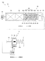
- FIG. 2 is a diagram showing an example of a schematic configuration of the vehicle height adjusting device 100.
- the motorcycle 1 as an example of a saddle-mounted vehicle includes a front wheel 2 which is a front wheel and a rear wheel 3 which is a rear wheel. Further, the motorcycle 1 includes a vehicle body frame 11 forming the skeleton of the motorcycle 1, a handle 12, a brake lever 13, and a vehicle body 10 having a seat 14.
- the front wheels 2 and the rear wheels 3 may be collectively referred to as "wheels", and the vehicle body 10 may be referred to as a "body”.
- the motorcycle 1 has a front fork 21 which is a first suspension device for connecting the front wheel 2 and the vehicle body 10. Further, the motorcycle 1 includes two brackets 15 for holding two front forks 21 arranged on the left and right sides of the front wheel 2, and a shaft 16 arranged between the two brackets 15. The shaft 16 is rotatably supported by the vehicle body frame 11.
- the front fork 21 includes a suspension spring 21s that absorbs an impact applied to the front wheel 2 from a road surface or the like, and a damping device 21d that attenuates the vibration of the suspension spring 21s.
- the motorcycle 1 has one rear suspension 22 which is a second suspension device for connecting the rear wheel 3 and the vehicle body 10 on the left side and the right side of the rear wheel 3.
- the rear suspension 22 includes a suspension spring 22s, which is a spring that absorbs an impact applied to the rear wheels 3 from a road surface or the like, and a damping device 22d that damps the vibration of the suspension spring 22s.
- the front fork 21 and the rear suspension 22 may be collectively referred to as a "suspension device 23".
- the suspension spring 21s and the suspension spring 22s may be collectively referred to as "spring 23s”.
- the motorcycle 1 includes an adjusting unit 70 that adjusts the height of the vehicle body 10, in other words, the vehicle height by changing the initial load (preload) applied to the spring 23s. Further, the motorcycle 1 is provided with a control device 50 that controls the initial load of the spring 23s.
- the adjusting unit 70 is provided in the suspension device 23, and includes a jack unit 71 that adjusts the length of the spring 23s, and a supply device 80 that supplies oil to the jack chamber 72 of the jack unit 71.
- the jack portion 71 has a support member 73 that supports the end portion of the spring 23s on the vehicle body side, and a forming member 74 that forms the jack chamber 72 together with the support member 73, and is inside the jack chamber 72.
- the length of the spring 23s is adjusted by moving the support member 73 according to the amount of oil in the spring 23s. It can be exemplified that the support member 73, the jack chamber 72, and the forming member 74 are realized by the support member, the jack chamber, and the hydraulic jack of the rear suspension or the front fork described in Patent Document 1, respectively.
- the jack portion 71 is provided with a movement amount sensor 75 that detects the movement amount of the support member 73.
- the movement amount of the support member 73 detected by the movement amount sensor 75 is the movement amount when the movement amount when the support member 73 is located at the reference position is set to 0.
- the reference position is the position of the support member 73 when the oil in the jack chamber 72 is 0.
- the movement amount sensor 75 for example, a coil is wound around the outer peripheral surface of the forming member 74, the support member 73 is made of a magnetic material, and the support member uses the inductance of the coil that changes according to the movement of the support member 73 with respect to the forming member 74. It can be exemplified that it is a sensor that detects the movement amount of 73.
- the supply device 80 includes a housing 81 for storing oil and a columnar piston 82 that slides in the housing 81.
- a storage chamber 83 for storing oil is formed on the inner surface of the housing 81 and in the space surrounded by the piston 82.
- the supply device 80 includes a motor 84, a speed reducer 85 that reduces the rotational speed of the motor 84, and a screw 86 connected to the output shaft 85a of the speed reducer 85.
- the motor 84 is a direct current (DC) motor with a brush. The drive of the motor 84 is controlled by the control device 50.
- the speed reducer 85 is a planetary speed reducer using a well-known planetary gear mechanism.
- the screw 86 has three columnar parts having different diameters, the first part 86a, the second part 86b, and the third part 86c, from one side (right side in FIG. 2) to the other side (FIG. 2). In 2, it is held in order from the left side).
- the outer diameter of the second part 86b is larger than the outer diameter of the first part 86a and the outer diameter of the third part 86c.
- a male screw 86d is formed on the outer peripheral surface of the first portion 86a.
- the output shaft 85a of the speed reducer 85 is fitted inside the third part 86c. As a result, the screw 86 rotates integrally with the output shaft 85a of the speed reducer 85.
- the supply device 80 has a nut 87 formed with a female screw 87a that meshes with a male screw 86d formed in the first portion 86a of the screw 86.
- the nut 87 has a flange 87b at the other end.
- the supply device 80 includes an intervening member 88 interposed between the flange 87b of the nut 87 and the piston 82, and a cylindrical collar 89 arranged inside the intervening member 88 and outside the nut 87. It has a cylindrical collar 90 arranged on the outside of the intervening member 88.
- the intervening member 88 is an elastic member, and is sandwiched between the piston 82 and the flange 87b of the nut 87 in a state of being elastically deformed by being pressed by the piston 82 that receives a force from oil. As a result, the intervening member 88 suppresses the rotation of the nut 87 as the screw 86 rotates.
- the supply device 80 has a bearing 91 that rotatably supports the screw 86, and a support member 92 that supports the bearing 91.
- the bearing 91 is arranged between the support member 92 and the second portion 86b of the screw 86.
- the piston 82, the motor 84, the speed reducer 85, the screw 86, the nut 87, the intervening member 88, the collar 89, the collar 90, the bearing 91, and the support member 92 described above are housed in the housing 81.
- the supply device 80 is mounted on the housing 81 and is provided between the storage chamber 83 and the jack chamber 72 of the jack portion 71 to allow oil to flow between the storage chamber 83 and the jack chamber 72. It is equipped with a hose 93.
- the shaft of the motor 84 of the supply device 80 rotates in one direction, so that the screw 86 rotates in one direction and the nut 87 is on one side in the rotation axis direction.
- the collar 89, the collar 90, and the intervening member 88 receive a force from the other side in the rotation axis direction toward one side, and move the piston 82 to one side.
- the piston 82 discharges the oil from the storage chamber 83.
- oil is supplied into the jack chamber 72 via the hose 93.
- the support member 73 moves to the wheel side (right side in FIG. 2) with respect to the forming member 74, in other words, the amount of movement of the support member 73 from the reference position becomes large, and the spring length of the spring 23s becomes short. ..
- the spring length of the spring 23s When the spring length of the spring 23s is shortened, the spring force by which the spring 23s pushes the support member 73 becomes larger than before the support member 73 moves with respect to the forming member 74. As a result, even if a force acts from the vehicle body to the wheel side, the initial load that does not change the relative positions of the two becomes large. In such a case, when the same force is applied from the vehicle body side to the wheel side, the sinking amount of the suspension device 23 (change in the distance between the vehicle body and the wheels) becomes small.
- the shaft of the motor 84 of the supply device 80 rotates in the other direction, so that the screw 86 rotates in the other direction.
- the force from the piston 82 that receives the oil force of the storage chamber 83 acts on the flange 87b of the nut 87 via the collar 89, the collar 90, and the intervening member 88, and the nut 87 moves to the other side in the rotation axis direction. do.
- the volume of the storage chamber 83 increases.
- the support member 73 discharges the oil in the jack chamber 72 and supplies it to the storage chamber 83.
- the support member 73 moves to the vehicle body side (left side in FIG. 2) with respect to the forming member 74, in other words, the amount of movement of the support member 73 from the reference position becomes small, and the spring length of the spring 23s becomes long. ..
- the adjusting unit 70 configured as described above, the vehicle height adjusting device 100 for adjusting the vehicle height of the motorcycle 1 by the control device 50 and the like are configured.
- FIG. 3 is a diagram showing an example of a block diagram of the control device 50.
- the control device 50 includes a CPU, a ROM in which programs executed by the CPU, various data, and the like are stored, a RAM used as a working memory of the CPU, and an EEPROM which is a non-volatile memory. .. An output signal from the movement amount sensor 75 or the like is input to the control device 50.
- the control device 50 includes a setting unit 51 for setting a target current It to be supplied to the motor 84, a control unit 52 for controlling the drive of the motor 84, and a drive unit 53 for driving the motor 84. Further, the control device 50 includes a detection unit 54 that detects the motor current Im that actually flows through the motor 84, and a detection unit 60 that detects that the motor 84 is in the shaft locked state.
- the setting unit 51, the control unit 52, and the detection unit 60 are realized by the CPU executing software stored in a storage area such as a ROM.
- the control unit 52 performs feedback control so that the deviation between the target current It set by the setting unit 51 and the motor current Im detected by the detection unit 54 becomes zero.
- the drive unit 53 has, for example, a transistor (FET) as a switching element connected between the positive electrode side line of the power supply and the coil of the motor 84. Then, the drive unit 53 controls the drive of the motor 84 by driving the gate of the transistor and switching the transistor.
- the detection unit 54 detects the motor current Im flowing through the motor 84 from the voltage generated across the shunt resistor connected to the drive unit 53.
- the setting unit 51 moves the piston 82 so that the target value Lt of the movement amount of the support member 73 of the jack unit 71 and the detection value La grasped by using the output value of the movement amount sensor 75 match.
- Set the target current It It can be exemplified that the target value Lt is a value corresponding to the target vehicle height selected by the user via the user interface provided on the motorcycle 1.
- the setting unit 51 sets the target current It to a predetermined first value in order to raise the vehicle height.
- the setting unit 51 sets the target current It to a second value predetermined in order to lower the vehicle height.
- a current in the direction of rotating the motor 84 to move the piston 82 to discharge oil from the storage chamber 83 is added, and the motor 84 is rotated to move the piston 82 to discharge oil from the jack chamber 72.
- the first value is 8A and the second value is -8A when the current in the direction is negative.
- the setting unit 51 sets the target current It to the second value in order to move the piston 82 in the direction of discharging the oil from the jack chamber 72. ..
- the setting unit 51 sets the target current It to 0. Further, the setting unit 51 sets the target current It to 0 when the detection unit 60 detects that the motor 84 is in the shaft locked state even when the subtraction value ⁇ L is not 0.
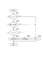
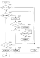
- FIG. 4 is a flowchart showing an example of a procedure for setting the target current It performed by the setting unit 51.
- the setting unit 51 repeatedly executes this process, for example, in a predetermined control cycle (for example, every 1 millisecond).
- the setting unit 51 determines whether or not the detection unit 60 has detected that the motor 84 is in the shaft locked state (S402). That is, the setting unit 51 determines whether or not a signal indicating that the shaft is in the locked state has been acquired from the detection unit 60.
- the setting unit 51 determines whether or not the subtraction value ⁇ L is larger than 0 (S403). Then, when the subtraction value ⁇ L is larger than 0 (Yes in S403), the setting unit 51 sets the target current It to the first value in order to move the piston 82 in the direction of discharging the oil from the storage chamber 83. (S404). On the other hand, when the subtraction value ⁇ L is smaller than 0 (No in S403), the setting unit 51 sets the target current It to the second value in order to move the piston 82 in the direction of discharging oil from the jack chamber 72. (S405).
- the setting unit 51 sets the target current It to 0 (S406).
- the setting unit 51 sets the target current It to 0 (S406).
- the setting unit 51 determines whether or not the absolute value of the subtraction value ⁇ L is larger than the predetermined reference value, and if the absolute value of the subtraction value ⁇ L is equal to or less than the reference value, sets the target current It to 0A.
- the target current It may be set to the first value or the second value according to the sign of the subtraction value ⁇ L.
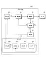
- FIG. 5 is a diagram showing an example of a block diagram of the detection unit 60.
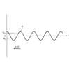
- FIG. 6 is a diagram showing an example of the waveform R output from the filter 611.
- the detection unit 60 uses the frequency of the motor current Im detected by the detection unit 54 (in other words, the frequency of the waveform R) to determine whether or not the motor 84 is in a rotating state, and a determination unit 61.
- a determination unit 62 for determining whether or not the motor 84 is in the shaft locked state is provided by using the determination result of 61.
- the determination unit 61 has a filter 611 that filters the motor current Im detected by the detection unit 54.
- the filter 611 has an LPF 611a that performs a filtering process corresponding to the low-pass filter, and an HPF 611b that performs a filtering process corresponding to the high-pass filter.
- the filter 611 outputs the waveform R illustrated in FIG. 6, in which the DC component and noise are removed from the motor current Im.
- the filter 611 may output the waveform R from the output from the HPF 611b by removing the minute increase / decrease vibration generated by noise.
- the determination unit 61 has a detection unit 612 that detects that the waveform R output from the filter 611 has passed 0 (hereinafter, may be referred to as “zero cross”).
- the detection unit 612 detects the zero cross by grasping that the sign of two consecutive values of the waveform R output from the filter 611 has changed in a predetermined control cycle. More specifically, the detection unit 612 makes a zero cross when the sign of the value obtained by multiplying the current value R n of the waveform R illustrated in FIG. 6 and the previous value R n-1 is negative. To detect.
- the determination unit 61 has a counting unit 613 that counts the number of zero crosses detected by the detection unit 612. The count unit 613 adds 1 to the count value X each time the detection unit 612 detects a zero cross. In addition, the counting unit 613 determines whether or not a predetermined period, which is a predetermined period, has elapsed. Then, when the predetermined period elapses, the counting unit 613 outputs the count value X when the predetermined period elapses and resets the count value X. In addition, it can be exemplified that the predetermined period is 250 (msec).
- the determination unit 61 has a determination unit 614 for determining the rotation state of the rotation shaft of the motor 84.
- the determination unit 614 determines whether or not the count value X output from the count unit 613 in a predetermined period is equal to or greater than a predetermined reference value Xt, and when the count value X is less than the reference value Xt. Judges that it is in a non-rotating state. On the other hand, the determination unit 614 determines that the rotation state is in effect when the count value X is equal to or greater than the reference value Xt.
- the determination unit 614 determines that the motor 84 is in the non-rotating state
- the determination unit 614 turns on the non-rotating state flag, which is a flag indicating that the motor 84 is in the non-rotating state, in a predetermined flag recording area provided in the RAM.
- the determination unit 614 determines that the rotation state is in effect
- the determination unit 614 turns off the non-rotation state flag.
- the determination unit 61 determines that the waveform R is in a rotating state when the number of zero crosses of the waveform R in a predetermined period is equal to or greater than the reference value Xt. On the other hand, the determination unit 61 determines that the waveform R is in a non-rotating state when the number of zero crosses of the waveform R in a predetermined period is less than the reference value Xt. In other words, when the number of zero crosses of the waveform R in the predetermined period is less than the reference value Xt, the determination unit 61 determines that the rotation speed of the motor 84 is a non-rotational state smaller than a predetermined predetermined speed.
- the predetermined speed is a speed uniquely determined by the type of the motor 84, the predetermined period, and the reference value Xt.
- the motor 84 is a DC motor with a 2-pole, 3-slot brush
- the value is Xt ⁇ 60 (s) / (6 ⁇ predetermined period (s)).
- the determination unit 62 has a supply determination unit 621 that determines whether or not the current is being supplied to the motor 84.
- the supply determination unit 621 determines that the motor current is in the supply state when the absolute value of the motor current Im is equal to or greater than a predetermined reference value Imt. It can be exemplified that the reference value Imt is 0.1 (A).
- the determination unit 62 has a counting unit 622 that counts the number of times that the supply determination unit 621 determines that the supply state is in the supply state after the determination unit 61 determines that the rotation state is in effect.
- the count unit 622 adds 1 to the count value Y each time the supply determination unit 621 determines that the supply state is in the supply state. However, the count unit 622 resets the count value Y when the determination unit 61 determines that the rotation state is in effect.
- the determination unit 62 has a determination unit 623 that determines that the shaft is locked when the count value Y counted by the count unit 622 exceeds a predetermined reference value Yt.
- the determination unit 623 acquires the count value Y counted by the count unit 622, and determines whether or not the count value Y exceeds the reference value Yt. Then, the determination unit 623 determines that the shaft is in the shaft lock state when the count value Y exceeds the reference value Yt, and outputs a signal indicating that the shaft is in the shaft lock state.
- the determination unit 623 does not determine that the shaft is locked and does not output a signal indicating that the shaft is locked.
- the determination unit 62 has been in the supply state since the count value Y becomes 0, for example, when the determination unit 61 determines that the rotation state is set and the count value Y is reset.
- the number of times of continuous determination exceeds the reference value Yt, it is determined that the shaft is in the locked state.
- the detection unit 60 determines a period in which the absolute value of the motor current Im is equal to or greater than a predetermined reference value Imt from the time when the determination unit 623 of the determination unit 62 reaches 0. By determining that the period has continued, it is detected that the axis is locked. Then, the detection unit 60 outputs a signal indicating that the shaft is in the locked state.
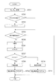
- FIG. 7 is a flowchart showing an example of the procedure of the rotation state determination process performed by the determination unit 61.
- the determination unit 61 repeatedly executes this process, for example, in a predetermined control cycle (for example, every 1 millisecond).
- the determination unit 61 acquires the current value R n and the previous value R n-1 of the waveform R output from the filter 611 (S701).
- the determination unit 61 detected the zero cross by determining whether or not the sign of the value obtained by multiplying the current value R n acquired in S701 and the previous value R n-1 is negative. Whether or not it is determined (S702). These are the processes performed by the detection unit 612.
- the determination unit 61 When a zero cross is detected (Yes in S702), the determination unit 61 adds 1 to the count value X (X ⁇ X + 1) (S703). The determination unit 61 determines whether or not the predetermined period has elapsed after adding 1 to the count value X in S703 or when it is not determined that the zero cross is detected in S702 (No in S702) (No). S704). If the predetermined period has not elapsed (No in S704), the determination unit 61 ends this process.
- the determination unit 61 determines the count value X at this time as the count value X within the predetermined period (S705), and resets the count value X (S706). ..
- the processing of S703, S704, S705, and S706 is a processing performed by the counting unit 613.
- the determination unit 61 determines whether or not the count value X determined in S705 is equal to or greater than the reference value Xt (S707). When the count value X is equal to or greater than the reference value Xt (Yes in S707), the determination unit 61 determines that the rotation state is in effect (S708). Then, the determination unit 61 turns off the non-rotation state flag (S709). On the other hand, when the count value X is not equal to or greater than the reference value Xt (No in S707), the determination unit 61 determines that it is in the non-rotating state (S710). Then, the determination unit 61 turns on the non-rotation state flag (S711). The processing of S707, S708, S709, S710, and S711 is a processing performed by the determination unit 614.
- FIG. 8 is a flowchart showing an example of the procedure of the axis lock state determination process performed by the determination unit 62.
- the determination unit 62 repeatedly executes this process, for example, in a predetermined control cycle (for example, every 1 millisecond).
- the determination unit 62 first determines whether or not the absolute value of the motor current Im is equal to or greater than the reference value Imt (S801). When the absolute value of the motor current Im is not equal to or more than the reference value Imt (No in S801), the determination unit 62 ends this process. This is a process performed by the supply determination unit 621.
- the determination unit 62 determines whether or not the non-rotation state flag is ON (S802). When the non-rotation state flag is ON (Yes in S802), the determination unit 62 adds 1 to the count value Y (Y ⁇ Y + 1) (S803). S802 and S803 are processes performed by the counting unit 622. After that, the determination unit 62 determines whether or not the count value Y exceeds the reference value Yt (S804). When the count value Y exceeds the reference value Yt (Yes in S804), the determination unit 62 determines that the axis is locked (S805).
- S804 and S805 are processes performed by the determination unit 623.
- the determination unit 62 resets the count value Y (S806) and ends this process.
- S806 is a process performed by the counting unit 622.
- the detection unit 60 of the control device 50 determines the shaft lock state by using the motor shaft state detection method described below.
- This motor shaft state detection method uses the detected current waveform of the motor 84 to determine whether or not the rotation speed of the motor 84 is in a non-rotational state lower than a predetermined speed, as an example of a rotation determination step. It has a rotation state determination process performed by 61. Further, S801 is provided as an example of a current determination step for determining whether or not the absolute value of the motor current Im supplied to the motor 84 is in a supply state larger than the reference value Imt.
- S802 to S805 are provided as an example of a determination step in which the motor 84 determines the shaft locked state when the rotation state determination process determines the non-rotation state and the supply state is determined in S801. .. Then, according to this motor shaft state detection method, for example, the shaft lock state is determined only when the current supplied to the motor 84 is larger than the reference value, regardless of changes in the environment. It is possible to detect with high accuracy that the motor 84 is in the shaft locked state.
- the waveform R is extracted using the current waveform of the motor 84, and the frequency of the extracted waveform R, that is, the number of zero crosses of the waveform R in a predetermined period is used to extract the waveform R of the motor 84. Grasp the rotation speed of.
- the configuration of the adjusting unit 70 can be simplified and inexpensive as compared with the configuration including a sensor that detects the rotation speed of the motor 84.
- control device 50 controls the operation of the motor 84 by using the control method described below.
- This control method is an example of a detection step of detecting a shaft lock state by the motor shaft state detection method and a stop step of stopping the supply of current to the motor 84 when the shaft lock state is detected in this detection step. It is provided with S406 of the setting process as. According to this control method, heat generation of the motor 84 can be suppressed with high accuracy regardless of changes in the environment.
- the detection unit 60 of the control device 50 can be regarded as a state detection device for the motor shaft having the following elements.
- This motor shaft state detection device is a determination unit as an example of a rotation determination unit that determines whether or not the rotation speed of the motor 84 is in a non-rotational state lower than a predetermined speed by using the detected current waveform of the motor 84.
- 61 and a supply determination unit 621 as an example of a current determination unit that determines whether or not the absolute value of the motor current Im supplied to the motor 84 is in a supply state larger than the reference value Imt.
- the determination unit 632 is provided as an example of a determination unit in which the motor 84 determines that the shaft is locked when the determination unit 61 determines that the non-rotating state is determined and the supply determination unit 621 determines that the supply state is present. ..
- the control device 50 is set as an example of a stop unit that stops the supply of current to the motor 84 when the state detection device for the motor shaft and the state detection device for the motor shaft determine that the shaft is in the locked state. It can be regarded as a control device of the motor 84 including the unit 51. According to this control device, it is possible to accurately suppress heat generation of the motor 84 regardless of changes in the environment.
- FIG. 9 is a flowchart showing an example of the procedure of the setting process according to the second embodiment performed by the setting unit 51.
- the detection unit 60 continuously locks the axis for a predetermined number of times with respect to the setting process according to the first embodiment described with reference to FIG.
- the set value of the target current It when the state is detected is different.
- the points different from the first embodiment will be described.
- the same reference numerals are used for the same processing, and detailed description thereof will be omitted. It can be exemplified that the predetermined number of times is two times.
- the setting unit 51 sets the target current It to the second value in order to move the piston 82 in the direction of discharging the oil from the jack chamber 72 (No). S405).
- the setting unit 51 adds 1 to the count value m (S901). After that, it is determined whether or not the count value m is 2 (S902). When the count value m has not reached 2 (No in S902), the setting unit 51 sets the target current It to the current value in the reverse direction in order to rotate the motor 84 in the reverse direction (S903). After that, it is determined whether or not the predetermined reversal period has elapsed (S904). If the inversion period has not elapsed (No in S904), the setting unit 51 waits until the inversion period elapses.
- the setting unit 51 sets the target current It to the original current value in order to return the rotation direction of the motor 84 (S905).
- the target current It is set, for example, over the inversion period. This is a process of setting the value to 2 and setting the target current It to the original first value again after the inversion period has elapsed.
- the setting unit 51 sets the count value m to 0 (S906) and sets the target current It to 0 (S406).
- the control device 50 controls the operation of the motor 84 by using the control method described below.
- This control method is an example of a detection step of detecting a shaft lock state by the motor shaft state detection method and a supply process of supplying a current in the reverse direction to the motor 84 when the shaft lock state is detected in this detection step. S903 and the like.
- the control device 50 according to the second embodiment supplies a current in the opposite direction to the motor 84 when the state detection device for the motor shaft and the state detection device for the motor shaft determine that the shaft is in the locked state.
- It can be regarded as a control device of the motor 84 including the setting unit 51 according to the second embodiment as an example of the supply unit. As a result, it is possible to prevent the motor 84 from generating heat with high accuracy regardless of changes in the environment.
- FIG. 10 is a diagram showing an example of a block diagram of the control device 250 according to the third embodiment.
- the control device 250 according to the third embodiment includes an estimation unit 270 that estimates the amount of movement of the support member 73 with respect to the control device 50 according to the first embodiment, and the setting unit 251 corresponding to the setting unit 51.
- the difference is that the target current It is set using the movement amount estimated by the estimation unit 270.
- the points different from the first embodiment will be described.
- the same reference numerals are used for the same ones, and detailed description thereof will be omitted.
- the estimation unit 270 has a filter 271 that filters the motor current Im detected by the detection unit 54.
- the filter 271 is the same as the filter 611, and outputs the waveform R illustrated in FIG. 6 in which the DC component and noise are removed from the motor current Im.
- the estimation unit 270 has a detection unit 272 that detects the zero cross of the waveform R output from the filter 271.
- the detection unit 272 is the same as the detection unit 612, and when the sign of the value obtained by multiplying the current value R n of the waveform R illustrated in FIG. 6 by the previous value R n-1 is negative. Detect zero cross.
- the estimation unit 270 has a grasping unit 273 that grasps the rotation angle ⁇ m of the motor 84, and a calculation unit 274 that calculates the movement amount of the support member 73 using the rotation angle ⁇ m grasped by the grasping unit 273. ing.
- the grasping unit 273 grasps the rotation angle ⁇ m by using the information that the detecting unit 272 has detected the zero cross and the sign of the motor current Im. For example, the grasping unit 273 has a positive count value which is the number of times the detection unit 272 detects zero cross when the sign of the motor current Im is positive, and the detection unit 272 when the sign of the motor current Im is negative. By subtracting the minus side count value, which is the number of times zero cross is detected, the rotation angle ⁇ m in the direction of discharging oil from the storage chamber 83 is grasped.
- the calculation unit 274 grasped the grasping unit 273 by a predetermined formula in view of the causal relationship between the rotation angle ⁇ m in the direction of discharging the oil from the storage chamber 83 and the movement amount of the support member 73. By substituting the rotation angle ⁇ m, the amount of movement of the support member 73 is calculated. The movement amount of the support member 73 calculated by the calculation unit 274 is the estimated movement amount Le estimated by the estimation unit 270.
- the setting unit 251 is different in that the setting unit 51 sets the target current It by using the estimated movement amount Le instead of the detected value La. That is, the setting unit 251 sets the target current It for moving the piston 82 so that the target value Lt and the estimated movement amount Le match.
- the setting method is as described above.
- the operation of the vehicle height adjusting device 100 according to the third embodiment configured as described above is controlled by a suspension device 23 having a spring 23s as an example of a spring and a control device 250 as an example of a motor control device.
- An adjusting unit 70 for adjusting the initial load of the spring 23s using the motor 84 is provided.
- the control device 250 determines that the shaft is locked by the estimation unit 270 that estimates the amount of movement of the support member 73 that supports the end of the spring 23s and the detection unit 60 using the detected current waveform of the motor 84. If not, the setting unit 251 for setting the target current It to be supplied to the motor 84 by using the estimated movement amount Le estimated by the estimation unit 270 is provided.
- the configuration of the adjusting unit 70 can be simplified and inexpensive as compared with the configuration including, for example, a sensor that detects the amount of movement of the support member 73.
- R Waveform, 1 ... Motorcycle (saddle type vehicle), 2 ... Front wheel, 3 ... Rear wheel, 10 ... Vehicle body, 21 ... Front fork (1st suspension device), 22 ... Rear suspension (2nd suspension device) , 22s ... Suspension spring (spring), 23 ... Suspension device, 23s ... Spring, 50 ... Control device, 51,251 ... Setting unit, 52 ... Control unit, 53 ... Drive unit, 54 ... Detection unit, 60 ... Detection unit, 61, 62 ... Judgment unit, 70 ... Adjustment unit, 71 ... Jack unit, 72 ... Jack chamber, 73 ... Support member, 75 ... Movement amount sensor, 80 ... Supply device, 81 ...
Landscapes
- Engineering & Computer Science (AREA)
- Mechanical Engineering (AREA)
- Power Engineering (AREA)
- Vehicle Body Suspensions (AREA)
Abstract
モータ軸の状態検知方法は、検出したモータの電流波形を用いて、モータの回転速度が予め定められた所定速度より小さい非回転状態であるか否かを判定する回転判定工程と、モータに供給された電流の絶対値が予め定められた基準値より大きい供給状態であるか否かを判定する電流判定工程と、回転判定工程にて非回転状態と判定され、かつ、電流判定工程にて供給状態と判定された場合にモータが軸ロック状態と判断する判断工程と、を有する。
Description
本発明は、モータ軸の状態検知方法、モータの制御方法、モータ軸の状態検知装置、モータの制御装置、車高調整装置、及び、鞍乗型車両に関する。
近年、車両の姿勢を整える等の目的で、車両の車両本体の高さ(車高)を調整する装置が提案されている。
例えば、特許文献1に記載されたフロントフォーク、リヤサスペンション、制御装置は、自動二輪車の車高を調整する装置の一例である。
また、特許文献2に記載された装置は、懸架スプリングの一端を支持する支持部材と、ジャッキ室とを有し、ジャッキ室への液体の供給により支持部材を移動させて車体の車高を変更する車高調整サスペンションと、を備えている。また、特許文献2に記載された装置は、油路を介してジャッキ室に接続されポンプ側ピストンの移動により容積が可変なポンプ側油室を有し、ポンプ側油室からジャッキ室に液体を供給する油圧ポンプと、ポンプ側ピストンを駆動するモータと、モータの駆動を制御する制御装置とを備えている。油圧ポンプは、より具体的には、薄肉円筒状のポンプ側シリンダと、円筒状のポンプ側シリンダの中心線方向の両端部それぞれを塞ぐ蓋部と、を備えている。
特許文献2に記載された装置の油圧ポンプにおいては、ピストン(ポンプ側ピストン)が貯留室(ポンプ側油室)から液体を排出し終わり、シリンダ(ポンプ側シリンダ)の端部を塞ぐ蓋部に突き当たった状態である場合に、液体を排出させるべくピストンを移動させるためにモータに電流を供給してもモータの回転軸はロック状態であるため回転しない。モータの回転軸がロック状態(以下において、この状態を「軸ロック状態」と称することがある。)である場合に、電流を供給し続けると、モータが発熱するおそれがあることから、モータの回転軸が軸ロック状態であることを検知することが重要となる。軸ロック状態を検知する手法として、例えば、モータに供給される電流値が基準値よりも大きい場合に軸ロック状態であると検知する手法が考えられる。しかしながら、低温でピストンが動き出すとき等、環境によっては、モータに供給される電流値が基準値よりも大きくなるおそれがあることから、真に軸ロック状態ではなくても、軸ロック状態であると判断するおそれがある。それゆえ、このような手法では、基準値を設定することができず、軸ロック状態であることを高精度に検知できない場合がある。
本発明は、環境の変化に関わらずモータが軸ロック状態であることを精度高く検知することができるモータ軸の状態検知方法等を提供することを目的とする。
本発明は、環境の変化に関わらずモータが軸ロック状態であることを精度高く検知することができるモータ軸の状態検知方法等を提供することを目的とする。
以下、本開示について説明する。
本開示の1つの態様は、検出したモータの電流波形を用いて、前記モータの回転速度が予め定められた所定速度より小さい非回転状態であるか否かを判定する回転判定工程と、前記モータに供給された電流の絶対値が予め定められた基準値より大きい供給状態であるか否かを判定する電流判定工程と、前記回転判定工程にて前記非回転状態と判定され、かつ、前記電流判定工程にて前記供給状態と判定された場合に前記モータが軸ロック状態と判断する判断工程と、を有するモータ軸の状態検知方法である。
ここで、前記回転判定工程は、前記電流波形を用いて抽出した波形の周波数を用いて前記回転速度を把握しても良い。
また、前記モータが、車高調整装置に備えられているモータであっても良い。
本開示の他の態様は、上記した態様に係るモータ軸の状態検知方法で前記軸ロック状態を検知する検知工程と、前記検知工程で前記軸ロック状態を検知した場合に、前記モータへの電流の供給を停止する停止工程と、を有するモータの制御方法である。
本開示の他の態様は、上記した態様に係るモータ軸の状態検知方法で前記軸ロック状態を検知する検知工程と、前記検知工程で前記軸ロック状態を検知した場合に、前記モータに逆方向の電流を供給する供給工程と、を有するモータの制御方法である。
本開示の他の態様は、検出したモータの電流波形を用いて、前記モータの回転速度が予め定められた所定速度より小さい非回転状態であるか否かを判定する回転判定部と、前記モータに供給された電流の絶対値が予め定められた基準値より大きい供給状態であるか否かを判定する電流判定部と、前記回転判定部にて前記非回転状態と判定され、かつ、前記電流判定部にて前記供給状態と判定された場合に前記モータが軸ロック状態と判断する判断部と、を備えるモータ軸の状態検知装置である。
ここで、前記回転判定部は、前記電流波形を用いて抽出した波形の周波数を用いて前記回転速度を把握しても良い。
本開示の他の態様は、上記した態様に係るモータ軸の状態検知装置と、前記モータ軸の状態検知装置で前記軸ロック状態と判断した場合に、前記モータへの電流の供給を停止する停止部と、を備えるモータの制御装置である。
本開示の他の態様は、上記した態様に係るモータ軸の状態検知装置と、前記モータ軸の状態検知装置で前記軸ロック状態と判断した場合に、前記モータに逆方向の電流を供給する供給部と、を備えるモータの制御装置である。
本開示の他の態様は、ばねを有する懸架装置と、上記した態様に係るモータの制御装置によって動作が制御される前記モータを用いて前記ばねの荷重を調整する調整部と、を備える車高調整装置である。
ここで、前記モータの制御装置は、検出したモータの電流波形を用いて、前記ばねの端部を支持する支持部材の移動量を推定する推定部と、前記モータ軸の状態検知装置で前記軸ロック状態と判断していない場合に、前記推定部が推定した前記移動量を用いて、前記モータに供給する目標電流を設定する設定部と、を備えてもよい。
本開示の他の態様は、車両本体と、前記車両本体の前側に配置される前輪、及び、前記車両本体の後側に配置される後輪と、前記車両本体と前記前輪との間に配置される第1懸架装置と、前記車両本体と前記後輪との間に配置される、ばねを有する第2懸架装置と、少なくとも前記ばねの荷重を調整する上記した態様に係る車高調整装置と、を備える鞍乗型車両である。
本発明によれば、環境の変化に関わらずモータが軸ロック状態であることを精度高く検知することができるモータ軸の状態検知方法等を提供することができる。
以下、添付図面を参照して、本発明の実施の形態について詳細に説明する。なお、以下に示す形態は本発明の実施の形態の一例であり、本発明は、以下に示す形態に限定されない。
<第1の実施形態>
図1は、第1の実施形態に係る自動二輪車1の概略構成の一例を示す図である。
図2は、車高調整装置100の概略構成の一例を示す図である。
鞍乗型車両の一例としての自動二輪車1は、前側の車輪である前輪2と、後側の車輪である後輪3と、を備えている。また、自動二輪車1は、自動二輪車1の骨格をなす車体フレーム11と、ハンドル12と、ブレーキレバー13と、シート14とを有する車両本体10を備えている。以下の説明において、前輪2と後輪3とをまとめて「車輪」と称し、車両本体10を「車体」と称する場合もある。
図1は、第1の実施形態に係る自動二輪車1の概略構成の一例を示す図である。
図2は、車高調整装置100の概略構成の一例を示す図である。
鞍乗型車両の一例としての自動二輪車1は、前側の車輪である前輪2と、後側の車輪である後輪3と、を備えている。また、自動二輪車1は、自動二輪車1の骨格をなす車体フレーム11と、ハンドル12と、ブレーキレバー13と、シート14とを有する車両本体10を備えている。以下の説明において、前輪2と後輪3とをまとめて「車輪」と称し、車両本体10を「車体」と称する場合もある。
また、自動二輪車1は、前輪2と車両本体10とを連結する第1懸架装置であるフロントフォーク21を有している。また、自動二輪車1は、前輪2の左右それぞれに配置された2つのフロントフォーク21を保持する2つのブラケット15と、2つのブラケット15の間に配置されたシャフト16と、を備えている。シャフト16は、車体フレーム11に回転可能に支持されている。フロントフォーク21は、路面等から前輪2に加わった衝撃を吸収する懸架スプリング21sと、懸架スプリング21sの振動を減衰する減衰装置21dと、を備えている。
また、自動二輪車1は、後輪3と車両本体10とを連結する第2懸架装置であるリヤサスペンション22を、後輪3の左側と右側にそれぞれ1つずつ有している。リヤサスペンション22は、路面等から後輪3に加わった衝撃を吸収するばねである懸架スプリング22sと、懸架スプリング22sの振動を減衰する減衰装置22dと、を備えている。
なお、以下の説明において、フロントフォーク21とリヤサスペンション22とをまとめて「懸架装置23」と称する場合もある。また、懸架スプリング21sと懸架スプリング22sとをまとめて「スプリング23s」と称する場合もある。
なお、以下の説明において、フロントフォーク21とリヤサスペンション22とをまとめて「懸架装置23」と称する場合もある。また、懸架スプリング21sと懸架スプリング22sとをまとめて「スプリング23s」と称する場合もある。
また、自動二輪車1は、スプリング23sに付与する初期荷重(プリロード)を変更することにより、車両本体10の高さ、言い換えれば、車高を調整する調整部70を備えている。
また、自動二輪車1は、スプリング23sの初期荷重を制御する制御装置50を備えている。
また、自動二輪車1は、スプリング23sの初期荷重を制御する制御装置50を備えている。
(調整部70)
調整部70は、懸架装置23に設けられて、スプリング23sの長さを調整するジャッキ部71と、ジャッキ部71のジャッキ室72にオイルを供給する供給装置80と、を備えている。
ジャッキ部71は、図2に示すように、スプリング23sの車体側の端部を支持する支持部材73と、支持部材73とともにジャッキ室72を形成する形成部材74とを有し、ジャッキ室72内のオイルの量に応じて支持部材73が移動することで、スプリング23sの長さを調整する。支持部材73、ジャッキ室72、形成部材74は、それぞれ、特許文献1に記載されたリヤサスペンション又はフロントフォークの支持部材、ジャッキ室、油圧ジャッキにて実現されることを例示することができる。
また、ジャッキ部71は、支持部材73の移動量を検出する移動量センサ75を備えている。移動量センサ75が検出する支持部材73の移動量は、支持部材73が基準位置に位置するときの移動量を0とした場合の移動量である。基準位置は、ジャッキ室72内のオイルが0のときの支持部材73の位置である。移動量センサ75は、例えば、形成部材74の外周面にコイルを巻くとともに、支持部材73を磁性体とし、形成部材74に対する支持部材73の移動に応じて変化するコイルのインダクタンスを用いて支持部材73の移動量を検出するセンサであることを例示することができる。
供給装置80は、図2に示すように、オイルを貯留するハウジング81と、ハウジング81内を摺動する円柱状のピストン82と、を備えている。ハウジング81の内面、及び、ピストン82にて囲まれる空間に、オイルを貯留する貯留室83が形成される。
また、供給装置80は、モータ84と、モータ84の回転速度を減速させる減速機85と、減速機85の出力軸85aに連結されたスクリュー86とを備えている。
モータ84は、ブラシ付きの直流(DC)モータであることを例示することができる。モータ84の駆動は、制御装置50によって制御される。減速機85は、周知の遊星歯車機構を用いた遊星減速機であることを例示することができる。
スクリュー86は、それぞれ径が異なる3つの円柱状の部位である、第1部86a、第2部86b、第3部86cを、回転軸方向の一方側(図2では右側)から他方側(図2では左側)にかけて順に有する。第2部86bの外径は、第1部86aの外径及び第3部86cの外径よりも大きい。第1部86aの外周面に、雄ねじ86dが形成されている。第3部86cの内側には、減速機85の出力軸85aが嵌め込まれている。これにより、スクリュー86は、減速機85の出力軸85aと一体的に回転する。
また、供給装置80は、スクリュー86の第1部86aに形成された雄ねじ86dと噛み合う雌ねじ87aが形成されたナット87を有している。ナット87は、他方側の端部にフランジ87bを有している。
また、供給装置80は、ナット87のフランジ87bと、ピストン82との間に介在する介在部材88と、介在部材88の内側であってナット87の外側に配置された円筒状のカラー89と、介在部材88の外側に配置された円筒状のカラー90とを有している。介在部材88は、弾性部材であり、オイルから力を受けたピストン82により加圧されることにより弾性変形した状態で、ピストン82とナット87のフランジ87bとの間に挟み込まれている。これにより、介在部材88は、スクリュー86の回転に従って、ナット87が回転することを抑制する。
また、供給装置80は、ナット87のフランジ87bと、ピストン82との間に介在する介在部材88と、介在部材88の内側であってナット87の外側に配置された円筒状のカラー89と、介在部材88の外側に配置された円筒状のカラー90とを有している。介在部材88は、弾性部材であり、オイルから力を受けたピストン82により加圧されることにより弾性変形した状態で、ピストン82とナット87のフランジ87bとの間に挟み込まれている。これにより、介在部材88は、スクリュー86の回転に従って、ナット87が回転することを抑制する。
また、供給装置80は、スクリュー86を回転可能に支持するベアリング91と、ベアリング91を支持する支持部材92とを有している。ベアリング91は、支持部材92と、スクリュー86の第2部86bとの間に配置されている。
上述した、ピストン82、モータ84、減速機85、スクリュー86、ナット87、介在部材88、カラー89、カラー90、ベアリング91、及び、支持部材92は、ハウジング81内に収容されている。
そして、供給装置80は、ハウジング81に装着されるとともに、貯留室83と、ジャッキ部71のジャッキ室72との間に設けられて、貯留室83とジャッキ室72との間でオイルを流通させるホース93を備えている。
上述した、ピストン82、モータ84、減速機85、スクリュー86、ナット87、介在部材88、カラー89、カラー90、ベアリング91、及び、支持部材92は、ハウジング81内に収容されている。
そして、供給装置80は、ハウジング81に装着されるとともに、貯留室83と、ジャッキ部71のジャッキ室72との間に設けられて、貯留室83とジャッキ室72との間でオイルを流通させるホース93を備えている。
以上のように構成された調整部70においては、供給装置80のモータ84の軸が一方の方向に回転することにより、スクリュー86が一方の方向に回転し、ナット87が回転軸方向の一方側に移動する。ナット87の移動に伴い、カラー89、カラー90及び介在部材88が、回転軸方向の他方側から一方側に向かう力を受け、ピストン82を一方側に移動させる。これにより、ピストン82が貯留室83からオイルを排出する。そして、ホース93を介して、ジャッキ室72内にオイルが供給される。その結果、支持部材73が形成部材74に対して車輪側(図2では右側)に移動し、言い換えれば、支持部材73の基準位置からの移動量が大きくなり、スプリング23sのバネ長が短くなる。
スプリング23sのバネ長が短くなると、支持部材73が形成部材74に対して移動する前と比べてスプリング23sが支持部材73を押すバネ力が大きくなる。その結果、車体から車輪側へ力が作用したとしても、両者の相対位置を変化させない初期荷重が大きくなる。かかる場合、車体側から車輪側に同じ力が作用した場合には、懸架装置23の沈み込み量(車体と車輪との間の距離の変化)が小さくなる。それゆえ、支持部材73が形成部材74に対して移動することでスプリング23sのバネ長が短くなると、支持部材73が形成部材74に対して移動する前と比べて、車両本体10の高さが上昇する(車高が高くなる)。
一方、供給装置80のモータ84の軸が他方の方向に回転することにより、スクリュー86が他方の方向に回転する。すると、カラー89、カラー90及び介在部材88を介して、貯留室83のオイルの力を受けるピストン82からの力がナット87のフランジ87bに作用し、ナット87が回転軸方向の他方側に移動する。ナット87の他方側への移動に伴い、貯留室83の容積が大きくなる。これにより、支持部材73がジャッキ室72内のオイルを排出し、これを貯留室83に供給する。その結果、支持部材73が形成部材74に対して車体側(図2では左側)に移動し、言い換えれば、支持部材73の基準位置からの移動量が小さくなり、スプリング23sのバネ長が長くなる。
スプリング23sのバネ長が長くなると、支持部材73が形成部材74に対して移動する前と比べてスプリング23sが支持部材73を押すバネ力が小さくなる。その結果、車体側から車輪側に同じ力が作用した場合には、懸架装置23の沈み込み量が大きくなる。それゆえ、支持部材73が形成部材74に対して移動することでスプリング23sのバネ長が長くなると、支持部材73が形成部材74に対して移動する前と比べて、車両本体10の高さが下降する(車高が低くなる)。
以上のように構成された調整部70、及び、制御装置50等により自動二輪車1の車高を調整する車高調整装置100が構成される。
(制御装置50)
次に、制御装置50について説明する。
図3は、制御装置50のブロック図の一例を示す図である。
制御装置50は、CPUと、CPUにて実行されるプログラムや各種データ等が記憶されたROMと、CPUの作業用メモリ等として用いられるRAMと、不揮発性メモリであるEEPROMと、を備えている。制御装置50には、移動量センサ75等からの出力信号が入力される。
次に、制御装置50について説明する。
図3は、制御装置50のブロック図の一例を示す図である。
制御装置50は、CPUと、CPUにて実行されるプログラムや各種データ等が記憶されたROMと、CPUの作業用メモリ等として用いられるRAMと、不揮発性メモリであるEEPROMと、を備えている。制御装置50には、移動量センサ75等からの出力信号が入力される。
制御装置50は、モータ84に供給する目標電流Itを設定する設定部51と、モータ84の駆動を制御する制御部52と、モータ84を駆動させる駆動部53と、を備えている。また、制御装置50は、モータ84に実際に流れるモータ電流Imを検出する検出部54と、モータ84が軸ロック状態であることを検知する検知部60と、を備えている。設定部51、制御部52、及び、検知部60は、CPUがROM等の記憶領域に記憶されたソフトウェアを実行することにより実現される。
制御部52は、設定部51にて設定された目標電流Itと、検出部54にて検出されたモータ電流Imとの偏差が0となるようにフィードバック制御を行う。
駆動部53は、例えば、電源の正極側ラインとモータ84のコイルとの間に接続された、スイッチング素子としてのトランジスタ(FET)を有している。そして、駆動部53は、このトランジスタのゲートを駆動してこのトランジスタをスイッチング動作させることにより、モータ84の駆動を制御する。
検出部54は、駆動部53に接続されたシャント抵抗の両端に生じる電圧から、モータ84に流れるモータ電流Imを検出する。
駆動部53は、例えば、電源の正極側ラインとモータ84のコイルとの間に接続された、スイッチング素子としてのトランジスタ(FET)を有している。そして、駆動部53は、このトランジスタのゲートを駆動してこのトランジスタをスイッチング動作させることにより、モータ84の駆動を制御する。
検出部54は、駆動部53に接続されたシャント抵抗の両端に生じる電圧から、モータ84に流れるモータ電流Imを検出する。
設定部51は、ジャッキ部71の支持部材73の移動量の目標値Ltと、移動量センサ75の出力値を用いて把握した検出値Laとが一致するように、ピストン82を移動させるための目標電流Itを設定する。目標値Ltは、自動二輪車1に設けられたユーザインターフェースを介してユーザにより選択された目標車高に応じた値であることを例示することができる。
設定部51は、貯留室83からオイルを排出させる方向にピストン82を移動させる場合には、目標電流Itを、車高を上昇させるために予め定められた第1の値に設定する。他方、設定部51は、ジャッキ室72からオイルを排出させる方向にピストン82を移動させる場合には、目標電流Itを、車高を下降させるために予め定められた第2の値に設定する。なお、貯留室83からオイルを排出させるべくピストン82を移動させるようにモータ84を回転させる方向の電流をプラス、ジャッキ室72からオイルを排出させるべくピストン82を移動させるようにモータ84を回転させる方向の電流をマイナスとした場合に、第1の値は8A、第2の値は-8Aであることを例示することができる。
設定部51は、貯留室83からオイルを排出させる方向にピストン82を移動させる場合には、目標電流Itを、車高を上昇させるために予め定められた第1の値に設定する。他方、設定部51は、ジャッキ室72からオイルを排出させる方向にピストン82を移動させる場合には、目標電流Itを、車高を下降させるために予め定められた第2の値に設定する。なお、貯留室83からオイルを排出させるべくピストン82を移動させるようにモータ84を回転させる方向の電流をプラス、ジャッキ室72からオイルを排出させるべくピストン82を移動させるようにモータ84を回転させる方向の電流をマイナスとした場合に、第1の値は8A、第2の値は-8Aであることを例示することができる。
設定部51は、ピストン82の移動方向を決定するにあたって、先ず、目標値Ltから、移動量センサ75の出力値を用いて把握した検出値Laを減算した減算値ΔL(=Lt-La)が0より大きいか否かを判断する。そして、減算値ΔLが0より大きい場合(ΔL>0)、設定部51は、ピストン82を、貯留室83からオイルを排出させる方向に移動させるべく、目標電流Itを第1の値に設定する。他方、減算値ΔLが0より小さい場合(ΔL<0)、設定部51は、ピストン82を、ジャッキ室72からオイルを排出させる方向に移動させるべく、目標電流Itを第2の値に設定する。一方、減算値ΔLが0である場合(ΔL=0)、設定部51は、目標電流Itを0に設定する。
また、設定部51は、減算値ΔLが0ではない場合であっても、モータ84が軸ロック状態であることを検知部60が検知した場合には、目標電流Itを0に設定する。
また、設定部51は、減算値ΔLが0ではない場合であっても、モータ84が軸ロック状態であることを検知部60が検知した場合には、目標電流Itを0に設定する。
図4は、設定部51が行う目標電流Itの設定処理の手順の一例を示すフローチャートである。
設定部51は、この処理を、例えば予め定めた制御周期にて(例えば1ミリ秒毎に)繰り返し実行する。
設定部51は、先ず、減算値ΔL(=Lt-La)が0であるか否かを判断する(S401)。減算値ΔLが0ではない場合(S401でNo)、設定部51は、モータ84が軸ロック状態であることを検知部60が検知したか否かを判断する(S402)。つまり、設定部51は、軸ロック状態である旨の信号を検知部60から取得したか否かを判断する。そして、軸ロック状態を検知していない場合(S402でNo)、設定部51は、減算値ΔLが0より大きいか否かを判断する(S403)。そして、減算値ΔLが0より大きい場合(S403でYes)、設定部51は、貯留室83からオイルを排出させる方向にピストン82を移動させるべく、目標電流Itを上記第1の値に設定する(S404)。他方、減算値ΔLが0より小さい場合(S403でNo)、設定部51は、ジャッキ室72からオイルを排出させる方向にピストン82を移動させるべく、目標電流Itを上記第2の値に設定する(S405)。
一方、軸ロック状態を検知した場合(S402でYes)、設定部51は、目標電流Itを0に設定する(S406)。また、減算値ΔLが0である場合(S401でYes)、設定部51は、目標電流Itを0に設定する(S406)。
なお、設定部51は、減算値ΔLの絶対値が予め定められた基準値より大きいか否かを判断し、減算値ΔLの絶対値が基準値以下である場合には目標電流Itを0Aに設定し、減算値ΔLの絶対値が基準値より大きい場合には、目標電流Itを、減算値ΔLの符号に応じて、上記第1の値又は上記第2の値に設定しても良い。
(検知部60)
図5は、検知部60のブロック図の一例を示す図である。
図6は、フィルタ611から出力された波形Rの一例を示す図である。
検知部60は、検出部54が検出したモータ電流Imの周波数(換言すれば波形Rの周波数)を用いてモータ84が回転している回転状態か否かを判定する判定部61と、判定部61の判定結果を用いて、モータ84が軸ロック状態であるか否かを判定する判定部62とを備えている。
図5は、検知部60のブロック図の一例を示す図である。
図6は、フィルタ611から出力された波形Rの一例を示す図である。
検知部60は、検出部54が検出したモータ電流Imの周波数(換言すれば波形Rの周波数)を用いてモータ84が回転している回転状態か否かを判定する判定部61と、判定部61の判定結果を用いて、モータ84が軸ロック状態であるか否かを判定する判定部62とを備えている。
判定部61は、検出部54が検出したモータ電流Imをフィルタリング処理するフィルタ611を有している。フィルタ611は、ローパスフィルタに対応するフィルタリング処理を施すLPF611aと、ハイパスフィルタに対応するフィルタリング処理を施すHPF611bとを有している。これにより、フィルタ611は、モータ電流Imから直流分及びノイズを除去した、図6に例示した波形Rを出力する。なお、フィルタ611は、HPF611bからの出力から、ノイズにより発生する微少な増減振動を除去した波形Rを出力しても良い。
また、判定部61は、フィルタ611から出力された波形Rが0を通過したこと(以下、「ゼロクロス」と称する場合がある。)を検出する検出部612を有している。検出部612は、フィルタ611から出力された波形Rの、予め定められた制御周期において連続する2つの値の符号が変わったことを把握することによりゼロクロスを検出する。より具体的には、検出部612は、図6に例示した波形Rの今回値Rnと、前回値Rn-1とを乗算することにより得た値の符号が負である場合にゼロクロスを検出する。
また、判定部61は、検出部612が検出したゼロクロスの回数をカウントするカウント部613を有している。カウント部613は、検出部612がゼロクロスを検出する毎にカウント値Xを1加算する。また、カウント部613は、予め定められた期間である所定期間が経過したか否かを判定する。そして、カウント部613は、所定期間が経過した場合には、所定期間が経過したときのカウント値Xを出力するとともに、カウント値Xをリセットする。なお、所定期間は、250(msec)であることを例示することができる。
また、判定部61は、モータ84の回転軸の回転状態を判断する判断部614を有している。判断部614は、カウント部613から出力された所定期間におけるカウント値Xが、予め定められた基準値Xt以上であるか否かを判定するとともに、カウント値Xが基準値Xt未満である場合には非回転状態であると判断する。他方、判断部614は、カウント値Xが基準値Xt以上である場合に回転状態であると判断する。また、判断部614は、非回転状態であると判断した場合には、モータ84が非回転状態である旨のフラグである非回転状態フラグを、RAMに設けられた所定のフラグ記録領域においてONにする。他方、判断部614は、回転状態であると判断した場合には、非回転状態フラグをOFFにする。
上述したように、判定部61は、所定期間における波形Rのゼロクロス数が基準値Xt以上である場合に回転状態と判定する。他方、判定部61は、所定期間における波形Rのゼロクロス数が基準値Xt未満である場合に非回転状態と判定する。言い換えれば、判定部61は、所定期間における波形Rのゼロクロス数が基準値Xt未満である場合に、モータ84の回転速度が予め定められた所定速度より小さい非回転状態であると判定する。所定速度は、モータ84のタイプ、所定期間、基準値Xtにより一義的に定まる速度である。例えば、モータ84が、2極、3スロットのブラシ付きの直流モータである場合には、モータ84の回転軸が1回転する毎にゼロクロス数が6となることから、所定速度(rpm)=基準値Xt×60(s)/(6×所定期間(s))である。
判定部62は、モータ84に電流が供給されている供給状態か否かを判定する供給判定部621を有している。供給判定部621は、モータ電流Imの絶対値が予め定められた基準値Imt以上である場合に供給状態であると判定する。基準値Imtは、0.1(A)であることを例示することができる。
また、判定部62は、判定部61が回転状態と判定した後に、供給判定部621が供給状態であると判定した回数をカウントするカウント部622を有している。カウント部622は、供給判定部621が供給状態であると判定する毎にカウント値Yを1加算する。ただし、カウント部622は、判定部61が回転状態と判定したときには、カウント値Yをリセットする。
また、判定部62は、カウント部622がカウントしたカウント値Yが、予め定められた基準値Ytを超えた場合に、軸ロック状態であると判断する判断部623を有している。判断部623は、カウント部622がカウントしたカウント値Yを取得するとともに、カウント値Yが基準値Ytを超えたか否かを判定する。そして、判断部623は、カウント値Yが基準値Ytを超えた場合に軸ロック状態であると判断し、軸ロック状態である旨の信号を出力する。他方、判断部623は、カウント値Yが基準値Yt以下である場合には軸ロック状態であるとは判断せず、軸ロック状態である旨の信号を出力しない。
このように、判定部62は、カウント値Yが0となったとき、例えば、判定部61が回転状態と判定してカウント値Yがリセットされたときから、供給判定部621が供給状態であると連続して判定した回数が基準値Ytを超えた場合に軸ロック状態であると判断する。
このように、判定部62は、カウント値Yが0となったとき、例えば、判定部61が回転状態と判定してカウント値Yがリセットされたときから、供給判定部621が供給状態であると連続して判定した回数が基準値Ytを超えた場合に軸ロック状態であると判断する。
上述したように、検知部60は、判定部62の判断部623が、カウント値Yが0となったときから、モータ電流Imの絶対値が予め定められた基準値Imt以上である期間が所定期間継続したと判断することで、軸ロック状態であることを検知する。そして、検知部60は、軸ロック状態である旨の信号を出力する。
図7は、判定部61が行う回転状態判定処理の手順の一例を示すフローチャートである。
判定部61は、この処理を、例えば予め定めた制御周期にて(例えば1ミリ秒毎に)繰り返し実行する。
判定部61は、先ず、フィルタ611から出力された波形Rの今回値Rnと前回値Rn-1とを取得する(S701)。その後、判定部61は、S701にて取得した今回値Rnと前回値Rn-1とを乗算することにより得た値の符号が負であるか否かを判断することによりゼロクロスを検出したか否かを判断する(S702)。これらは検出部612が行う処理である。
判定部61は、この処理を、例えば予め定めた制御周期にて(例えば1ミリ秒毎に)繰り返し実行する。
判定部61は、先ず、フィルタ611から出力された波形Rの今回値Rnと前回値Rn-1とを取得する(S701)。その後、判定部61は、S701にて取得した今回値Rnと前回値Rn-1とを乗算することにより得た値の符号が負であるか否かを判断することによりゼロクロスを検出したか否かを判断する(S702)。これらは検出部612が行う処理である。
ゼロクロスを検出した場合(S702でYes)、判定部61は、カウント値Xを1加算する(X←X+1)(S703)。判定部61は、S703にてカウント値Xを1加算した後、または、S702にてゼロクロスを検出したと判断していない場合(S702でNo)、所定期間が経過したか否かを判断する(S704)。所定期間が経過していない場合(S704でNo)、判定部61は、本処理を終了する。他方、所定期間が経過した場合(S704でYes)、判定部61は、このときのカウント値Xを、所定期間内のカウント値Xとして確定し(S705)、カウント値Xをリセットする(S706)。S703、S704、S705、及び、S706の処理は、カウント部613が行う処理である。
その後、判定部61は、S705にて確定したカウント値Xが基準値Xt以上であるか否かを判断する(S707)。カウント値Xが基準値Xt以上である場合(S707でYes)、判定部61は、回転状態であると判断する(S708)。そして、判定部61は、非回転状態フラグをOFFにする(S709)。他方、カウント値Xが基準値Xt以上ではない場合(S707でNo)、判定部61は、非回転状態であると判断する(S710)。そして、判定部61は、非回転状態フラグをONにする(S711)。S707、S708、S709、S710、及び、S711の処理は、判断部614が行う処理である。
図8は、判定部62が行う軸ロック状態判定処理の手順の一例を示すフローチャートである。
判定部62は、この処理を、例えば予め定めた制御周期にて(例えば1ミリ秒毎に)繰り返し実行する。
判定部62は、先ず、モータ電流Imの絶対値が基準値Imt以上であるか否かを判断する(S801)。モータ電流Imの絶対値が基準値Imt以上ではない場合(S801でNo)、判定部62は、本処理を終了する。これは、供給判定部621が行う処理である。
モータ電流Imの絶対値が基準値Imt以上である場合(S801でYes)、判定部62は、非回転状態フラグがONであるか否かを判断する(S802)。非回転状態フラグがONである場合(S802でYes)、判定部62は、カウント値Yを1加算する(Y←Y+1)(S803)。S802及びS803は、カウント部622が行う処理である。その後、判定部62は、カウント値Yが基準値Ytを超えたか否かを判断する(S804)。カウント値Yが基準値Ytを超えた場合(S804でYes)、判定部62は、軸ロック状態であると判断する(S805)。S804及びS805は、判断部623が行う処理である。
他方、非回転状態フラグがONではない場合(S802でNo)、判定部62は、カウント値Yをリセットし(S806)、本処理を終了する。S806は、カウント部622が行う処理である。
以上説明したように、制御装置50の検知部60は、以下に述べるモータ軸の状態検知方法を用いて軸ロック状態を判断する。このモータ軸の状態検知方法は、検出したモータ84の電流波形を用いて、モータ84の回転速度が所定速度より小さい非回転状態であるか否かを判定する回転判定工程の一例としての判定部61が行う回転状態判定処理を有している。また、モータ84に供給されたモータ電流Imの絶対値が基準値Imtより大きい供給状態であるか否かを判定する電流判定工程の一例としてのS801を有している。また、回転状態判定処理にて非回転状態と判定され、かつ、S801にて供給状態と判定された場合にモータ84が軸ロック状態と判断する判断工程の一例としてのS802~S805と、を有する。そして、このモータ軸の状態検知方法によれば、例えば、モータ84に供給された電流が基準値よりも大きいことのみで軸ロック状態であると判断するのと比べて、環境の変化に関わらずモータ84が軸ロック状態であることを精度高く検知することができる。
そして、判定部61が行う回転状態判定処理は、モータ84の電流波形を用いて波形Rを抽出するとともに、抽出した波形Rの周波数、つまり、所定期間における波形Rのゼロクロス数を用いてモータ84の回転速度を把握する。この処理を用いることで、例えば、モータ84の回転速度を検出するセンサを備える構成に比べて、調整部70の構成を簡易かつ低廉にすることができる。
そして、制御装置50は、以下に述べる制御方法を用いてモータ84の動作を制御する。この制御方法は、上記モータ軸の状態検知方法で軸ロック状態を検知する検知工程と、この検知工程で軸ロック状態を検知した場合に、モータ84への電流の供給を停止する停止工程の一例としての設定処理のS406と、を備える。この制御方法によれば、環境の変化に関わらず、モータ84が発熱することを精度高く抑制することができる。
また、制御装置50の検知部60は、以下の要素を備えるモータ軸の状態検知装置として捉えることができる。このモータ軸の状態検知装置は、検出したモータ84の電流波形を用いて、モータ84の回転速度が所定速度より小さい非回転状態であるか否かを判定する回転判定部の一例としての判定部61と、モータ84に供給されたモータ電流Imの絶対値が基準値Imtより大きい供給状態であるか否かを判定する電流判定部の一例としての供給判定部621と、を備える。また、判定部61にて非回転状態と判定され、かつ、供給判定部621にて供給状態と判定された場合にモータ84が軸ロック状態と判断する判断部の一例としての判断部632を備える。
そして、制御装置50は、上記モータ軸の状態検知装置と、このモータ軸の状態検知装置で軸ロック状態と判断した場合に、モータ84への電流の供給を停止する停止部の一例としての設定部51と、を備えるモータ84の制御装置として捉えることができる。この制御装置によれば、環境の変化に関わらず、モータ84が発熱することを精度高く抑制することができる。
<第2の実施形態>
図9は、設定部51が行う、第2の実施形態に係る設定処理の手順の一例を示すフローチャートである。
第2の実施形態に係る設定処理は、図4を用いて説明した第1の実施形態に係る設定処理に対して、予め定められた所定回数に亘って連続して、検知部60が軸ロック状態を検知した場合における、目標電流Itの設定値が異なる。以下、第1の実施形態と異なる点について説明する。第1の実施形態と第2の実施形態とで、同じ処理については同じ符号を用い、その詳細な説明は省略する。所定回数は2回であることを例示することができる。
図9は、設定部51が行う、第2の実施形態に係る設定処理の手順の一例を示すフローチャートである。
第2の実施形態に係る設定処理は、図4を用いて説明した第1の実施形態に係る設定処理に対して、予め定められた所定回数に亘って連続して、検知部60が軸ロック状態を検知した場合における、目標電流Itの設定値が異なる。以下、第1の実施形態と異なる点について説明する。第1の実施形態と第2の実施形態とで、同じ処理については同じ符号を用い、その詳細な説明は省略する。所定回数は2回であることを例示することができる。
設定部51は、先ず、減算値ΔL(=Lt-La)が0であるか否かを判断する(S401)。減算値ΔLが0ではない場合(S401でNo)、設定部51は、モータ84が軸ロック状態であることを検知部60が検知したか否かを判断する(S402)。そして、軸ロック状態を検知していない場合(S402でNo)、設定部51は、減算値ΔLが0より大きいか否かを判断する(S403)。そして、減算値ΔLが0より大きい場合(S403でYes)、設定部51は、貯留室83からオイルを排出させる方向にピストン82を移動させるべく、目標電流Itを第1の値に設定する(S404)。他方、減算値ΔLが0より小さい場合(S403でNo)、設定部51は、ジャッキ室72からオイルを排出させる方向にピストン82を移動させるべく、目標電流Itを第2の値に設定する(S405)。
一方、検知部60が軸ロック状態を検知した場合(S402でYes)、設定部51は、カウント値mを1加算する(S901)。その後、カウント値mが2であるか否かを判断する(S902)。カウント値mが2に到達していない場合(S902でNo)、設定部51は、モータ84を逆方向に回転させるべく、目標電流Itを逆方向の電流値に設定する(S903)。その後に、予め定められた反転期間が経過したか否かを判断する(S904)。反転期間が経過していない場合(S904でNo)、設定部51は、反転期間が経過するまで待機する。他方、反転期間が経過した場合(S904でYes)、設定部51は、モータ84の回転方向を戻すべく、目標電流Itを元の電流値に設定する(S905)。S903、S904、及び、S905の処理は、例えば、検知部60が軸ロック状態を検知したときの目標電流Itが第1の値である場合には、反転期間に亘って目標電流Itを例えば第2の値に設定し、反転期間が経過した後に、再度、目標電流Itを元の第1の値に設定する処理である。
一方、S902にてカウント値mが2に到達した場合(S902でYes)、設定部51は、カウント値mを0とし(S906)、目標電流Itを0に設定する(S406)。
一方、S902にてカウント値mが2に到達した場合(S902でYes)、設定部51は、カウント値mを0とし(S906)、目標電流Itを0に設定する(S406)。
以上、説明したように、第2の実施形態に係る制御装置50は、以下に述べる制御方法を用いてモータ84の動作を制御する。この制御方法は、上記モータ軸の状態検知方法で軸ロック状態を検知する検知工程と、この検知工程で軸ロック状態を検知した場合に、モータ84に逆方向の電流を供給する供給工程の一例としてのS903と、を備える。
また、第2の実施形態に係る制御装置50は、上記モータ軸の状態検知装置と、このモータ軸の状態検知装置で軸ロック状態と判断した場合に、モータ84に逆方向の電流を供給する供給部の一例としての第2の実施形態に係る設定部51と、を備えるモータ84の制御装置として捉えることができる。
これらにより、環境の変化に関わらず、モータ84が発熱することを精度高く抑制することができる。
また、第2の実施形態に係る制御装置50は、上記モータ軸の状態検知装置と、このモータ軸の状態検知装置で軸ロック状態と判断した場合に、モータ84に逆方向の電流を供給する供給部の一例としての第2の実施形態に係る設定部51と、を備えるモータ84の制御装置として捉えることができる。
これらにより、環境の変化に関わらず、モータ84が発熱することを精度高く抑制することができる。
<第3の実施形態>
図10は、第3の実施形態に係る制御装置250のブロック図の一例を示す図である。
第3の実施形態に係る制御装置250は、第1の実施形態に係る制御装置50に対して、支持部材73の移動量を推定する推定部270を備え、設定部51に相当する設定部251が、推定部270が推定した移動量を用いて目標電流Itを設定する点が異なる。以下、第1の実施形態と異なる点について説明する。第1の実施形態と第3の実施形態とで、同じものについては同じ符号を用い、その詳細な説明は省略する。
図10は、第3の実施形態に係る制御装置250のブロック図の一例を示す図である。
第3の実施形態に係る制御装置250は、第1の実施形態に係る制御装置50に対して、支持部材73の移動量を推定する推定部270を備え、設定部51に相当する設定部251が、推定部270が推定した移動量を用いて目標電流Itを設定する点が異なる。以下、第1の実施形態と異なる点について説明する。第1の実施形態と第3の実施形態とで、同じものについては同じ符号を用い、その詳細な説明は省略する。
推定部270は、検出部54が検出したモータ電流Imをフィルタリング処理するフィルタ271を有している。フィルタ271は、フィルタ611と同一であり、モータ電流Imから直流分及びノイズを除去した、図6に例示した波形Rを出力する。
また、推定部270は、フィルタ271から出力された波形Rのゼロクロスを検出する検出部272を有している。検出部272は、検出部612と同一であり、図6に例示した波形Rの今回値Rnと、前回値Rn-1とを乗算することにより得た値の符号が負である場合にゼロクロスを検出する。
また、推定部270は、フィルタ271から出力された波形Rのゼロクロスを検出する検出部272を有している。検出部272は、検出部612と同一であり、図6に例示した波形Rの今回値Rnと、前回値Rn-1とを乗算することにより得た値の符号が負である場合にゼロクロスを検出する。
また、推定部270は、モータ84の回転角度θmを把握する把握部273と、把握部273が把握した回転角度θmを用いて支持部材73の移動量を算出する算出部274と、を有している。
把握部273は、検出部272がゼロクロスを検出したとの情報と、モータ電流Imの符号とを用いて、回転角度θmを把握する。例えば、把握部273は、モータ電流Imの符号がプラスであるときに検出部272がゼロクロスを検出した回数であるプラス側カウント値から、モータ電流Imの符号がマイナスであるときに検出部272がゼロクロスを検出した回数であるマイナス側カウント値を減算することにより、貯留室83からオイルを排出させる方向の回転角度θmを把握する。
把握部273は、検出部272がゼロクロスを検出したとの情報と、モータ電流Imの符号とを用いて、回転角度θmを把握する。例えば、把握部273は、モータ電流Imの符号がプラスであるときに検出部272がゼロクロスを検出した回数であるプラス側カウント値から、モータ電流Imの符号がマイナスであるときに検出部272がゼロクロスを検出した回数であるマイナス側カウント値を減算することにより、貯留室83からオイルを排出させる方向の回転角度θmを把握する。
算出部274は、貯留室83からオイルを排出させる方向の回転角度θmと支持部材73の移動量との間には因果関係があることに鑑み予め定められた式に、把握部273が把握した回転角度θmを代入することにより、支持部材73の移動量を算出する。
算出部274が算出した支持部材73の移動量が、推定部270が推定した推定移動量Leである。
算出部274が算出した支持部材73の移動量が、推定部270が推定した推定移動量Leである。
設定部251は、設定部51に対して、検出値Laの代わりに推定移動量Leを用いて目標電流Itを設定する点が異なる。つまり、設定部251は、目標値Ltと推定移動量Leとが一致するように、ピストン82を移動させるための目標電流Itを設定する。設定手法は上述した通りである。
以上のように構成された第3の実施形態に係る車高調整装置100は、ばねの一例としてのスプリング23sを有する懸架装置23と、モータの制御装置の一例としての制御装置250によって動作が制御されるモータ84を用いてスプリング23sの初期荷重を調整する調整部70と、を備える。
そして、制御装置250は、検出したモータ84の電流波形を用いて、スプリング23sの端部を支持する支持部材73の移動量を推定する推定部270と、検知部60で軸ロック状態と判断していない場合に、推定部270が推定した推定移動量Leを用いて、モータ84に供給する目標電流Itを設定する設定部251と、を備える。
この制御装置250によれば、例えば、支持部材73の移動量を検出するセンサを備える構成に比べて、調整部70の構成を簡易かつ低廉にすることができる。
そして、制御装置250は、検出したモータ84の電流波形を用いて、スプリング23sの端部を支持する支持部材73の移動量を推定する推定部270と、検知部60で軸ロック状態と判断していない場合に、推定部270が推定した推定移動量Leを用いて、モータ84に供給する目標電流Itを設定する設定部251と、を備える。
この制御装置250によれば、例えば、支持部材73の移動量を検出するセンサを備える構成に比べて、調整部70の構成を簡易かつ低廉にすることができる。
R…波形、1…自動二輪車(鞍乗型車両)、2…前輪、3…後輪、10…車両本体、21…フロントフォーク(第1懸架装置)、22…リヤサスペンション(第2懸架装置)、22s…懸架スプリング(ばね)、23…懸架装置、23s…スプリング、50…制御装置、51,251…設定部、52…制御部、53…駆動部、54…検出部、60…検知部、61,62…判定部、70…調整部、71…ジャッキ部、72…ジャッキ室、73…支持部材、75…移動量センサ、80…供給装置、81…ハウジング、82…ピストン、83…貯留室、84…モータ、100…車高調整装置、270…推定部、611…フィルタ、612…検出部、613…カウント部、614…判断部、621…供給判定部、622…カウント部、623…判断部
Claims (12)
- 検出したモータの電流波形を用いて、前記モータの回転速度が予め定められた所定速度より小さい非回転状態であるか否かを判定する回転判定工程と、
前記モータに供給された電流の絶対値が予め定められた基準値より大きい供給状態であるか否かを判定する電流判定工程と、
前記回転判定工程にて前記非回転状態と判定され、かつ、前記電流判定工程にて前記供給状態と判定された場合に前記モータが軸ロック状態と判断する判断工程と、
を有するモータ軸の状態検知方法。 - 前記回転判定工程は、前記電流波形を用いて抽出した波形の周波数を用いて前記回転速度を把握する
請求項1に記載のモータ軸の状態検知方法。 - 前記モータが、車高調整装置に備えられているモータである、
請求項1又は2に記載のモータ軸の状態検知方法。 - 請求項1~3のいずれか1項に記載のモータ軸の状態検知方法で前記軸ロック状態を検知する検知工程と、
前記検知工程で前記軸ロック状態を検知した場合に、前記モータへの電流の供給を停止する停止工程と、
を有するモータの制御方法。 - 請求項1~3のいずれか1項に記載のモータ軸の状態検知方法で前記軸ロック状態を検知する検知工程と、
前記検知工程で前記軸ロック状態を検知した場合に、前記モータに逆方向の電流を供給する供給工程と、
を有するモータの制御方法。 - 検出したモータの電流波形を用いて、前記モータの回転速度が予め定められた所定速度より小さい非回転状態であるか否かを判定する回転判定部と、
前記モータに供給された電流の絶対値が予め定められた基準値より大きい供給状態であるか否かを判定する電流判定部と、
前記回転判定部にて前記非回転状態と判定され、かつ、前記電流判定部にて前記供給状態と判定された場合に前記モータが軸ロック状態と判断する判断部と、
を備えるモータ軸の状態検知装置。 - 前記回転判定部は、前記電流波形を用いて抽出した波形の周波数を用いて前記回転速度を把握する
請求項6に記載のモータ軸の状態検知装置。 - 請求項6又は7に記載のモータ軸の状態検知装置と、
前記モータ軸の状態検知装置で前記軸ロック状態と判断した場合に、前記モータへの電流の供給を停止する停止部と、
を備えるモータの制御装置。 - 請求項6又は7に記載のモータ軸の状態検知装置と、
前記モータ軸の状態検知装置で前記軸ロック状態と判断した場合に、前記モータに逆方向の電流を供給する供給部と、
を備えるモータの制御装置。 - ばねを有する懸架装置と、
請求項8又は9に記載のモータの制御装置によって動作が制御される前記モータを用いて前記ばねの荷重を調整する調整部と、
を備える車高調整装置。 - 前記モータの制御装置は、
検出したモータの電流波形を用いて、前記ばねの端部を支持する支持部材の移動量を推定する推定部と、
前記モータ軸の状態検知装置で前記軸ロック状態と判断していない場合に、前記推定部が推定した前記移動量を用いて、前記モータに供給する目標電流を設定する設定部と、
を備える請求項10に記載の車高調整装置。 - 車両本体と、
前記車両本体の前側に配置される前輪、及び、前記車両本体の後側に配置される後輪と、
前記車両本体と前記前輪との間に配置される第1懸架装置と、
前記車両本体と前記後輪との間に配置される、ばねを有する第2懸架装置と、
少なくとも前記ばねの荷重を調整する請求項10又は11に記載の車高調整装置と、
を備える鞍乗型車両。
Priority Applications (4)
| Application Number | Priority Date | Filing Date | Title |
|---|---|---|---|
| DE112020003869.6T DE112020003869T5 (de) | 2020-03-17 | 2020-03-17 | Motorwellenzustandsdetektionsverfahren, Motorsteuerverfahren, Motorwellenzustandsdetektionsvorrichtung, Motorsteuervorrichtung, Fahrzeughöhenanpassungsvorrichtung, Fahrzeug vom Satteltyp |
| PCT/JP2020/011694 WO2021186542A1 (ja) | 2020-03-17 | 2020-03-17 | モータ軸の状態検知方法、モータの制御方法、モータ軸の状態検知装置、モータの制御装置、車高調整装置、鞍乗型車両 |
| JP2020516501A JP6789444B1 (ja) | 2020-03-17 | 2020-03-17 | モータ軸の状態検知方法、モータの制御方法、モータ軸の状態検知装置、モータの制御装置、車高調整装置、鞍乗型車両 |
| US17/694,568 US12017496B2 (en) | 2020-03-17 | 2022-03-14 | Motor shaft state detection method, motor control method, motor shaft state detection device, motor control device, vehicle height adjustment device, saddle-type vehicle |
Applications Claiming Priority (1)
| Application Number | Priority Date | Filing Date | Title |
|---|---|---|---|
| PCT/JP2020/011694 WO2021186542A1 (ja) | 2020-03-17 | 2020-03-17 | モータ軸の状態検知方法、モータの制御方法、モータ軸の状態検知装置、モータの制御装置、車高調整装置、鞍乗型車両 |
Related Child Applications (1)
| Application Number | Title | Priority Date | Filing Date |
|---|---|---|---|
| US17/694,568 Continuation US12017496B2 (en) | 2020-03-17 | 2022-03-14 | Motor shaft state detection method, motor control method, motor shaft state detection device, motor control device, vehicle height adjustment device, saddle-type vehicle |
Publications (1)
| Publication Number | Publication Date |
|---|---|
| WO2021186542A1 true WO2021186542A1 (ja) | 2021-09-23 |
Family
ID=73452923
Family Applications (1)
| Application Number | Title | Priority Date | Filing Date |
|---|---|---|---|
| PCT/JP2020/011694 Ceased WO2021186542A1 (ja) | 2020-03-17 | 2020-03-17 | モータ軸の状態検知方法、モータの制御方法、モータ軸の状態検知装置、モータの制御装置、車高調整装置、鞍乗型車両 |
Country Status (4)
| Country | Link |
|---|---|
| US (1) | US12017496B2 (ja) |
| JP (1) | JP6789444B1 (ja) |
| DE (1) | DE112020003869T5 (ja) |
| WO (1) | WO2021186542A1 (ja) |
Families Citing this family (1)
| Publication number | Priority date | Publication date | Assignee | Title |
|---|---|---|---|---|
| WO2022113231A1 (ja) | 2020-11-26 | 2022-06-02 | 日立Astemo株式会社 | モータの制御方法、流体供給装置、車高調整装置、鞍乗型車両 |
Citations (5)
| Publication number | Priority date | Publication date | Assignee | Title |
|---|---|---|---|---|
| JP2004304880A (ja) * | 2003-03-28 | 2004-10-28 | Aisin Seiki Co Ltd | モータ異常検出装置及び車高調整装置 |
| JP2004308200A (ja) * | 2003-04-04 | 2004-11-04 | Yazaki Corp | モータ可動装置及びその操作制御方法 |
| JP5155055B2 (ja) * | 2008-07-31 | 2013-02-27 | アイシン精機株式会社 | 位置制御装置 |
| JP2016160968A (ja) * | 2015-02-27 | 2016-09-05 | 株式会社ショーワ | 車高調整装置 |
| JP2018144650A (ja) * | 2017-03-06 | 2018-09-20 | 株式会社ショーワ | 車高調整装置 |
Family Cites Families (4)
| Publication number | Priority date | Publication date | Assignee | Title |
|---|---|---|---|---|
| JP5348460B2 (ja) * | 2008-05-29 | 2013-11-20 | アイシン精機株式会社 | 状態記憶制御装置 |
| US8406955B2 (en) * | 2008-12-26 | 2013-03-26 | Kubota Corporation | Hydraulic suspension system for work vehicle |
| US8251376B2 (en) * | 2009-07-17 | 2012-08-28 | Shimano Inc. | Bicycle suspension having stroke and damper adjustment |
| DE102014206142A1 (de) * | 2013-08-14 | 2015-02-19 | Schaeffler Technologies Gmbh & Co. Kg | Vorrichtung zur Höhenverstellung eines Fahrzeugaufbaus |
-
2020
- 2020-03-17 JP JP2020516501A patent/JP6789444B1/ja active Active
- 2020-03-17 WO PCT/JP2020/011694 patent/WO2021186542A1/ja not_active Ceased
- 2020-03-17 DE DE112020003869.6T patent/DE112020003869T5/de active Pending
-
2022
- 2022-03-14 US US17/694,568 patent/US12017496B2/en active Active
Patent Citations (5)
| Publication number | Priority date | Publication date | Assignee | Title |
|---|---|---|---|---|
| JP2004304880A (ja) * | 2003-03-28 | 2004-10-28 | Aisin Seiki Co Ltd | モータ異常検出装置及び車高調整装置 |
| JP2004308200A (ja) * | 2003-04-04 | 2004-11-04 | Yazaki Corp | モータ可動装置及びその操作制御方法 |
| JP5155055B2 (ja) * | 2008-07-31 | 2013-02-27 | アイシン精機株式会社 | 位置制御装置 |
| JP2016160968A (ja) * | 2015-02-27 | 2016-09-05 | 株式会社ショーワ | 車高調整装置 |
| JP2018144650A (ja) * | 2017-03-06 | 2018-09-20 | 株式会社ショーワ | 車高調整装置 |
Also Published As
| Publication number | Publication date |
|---|---|
| JPWO2021186542A1 (ja) | 2021-09-23 |
| US12017496B2 (en) | 2024-06-25 |
| DE112020003869T5 (de) | 2022-05-05 |
| US20220203795A1 (en) | 2022-06-30 |
| JP6789444B1 (ja) | 2020-11-25 |
Similar Documents
| Publication | Publication Date | Title |
|---|---|---|
| JP6030459B2 (ja) | 車両の操舵制御装置 | |
| CN107074273B (zh) | 车辆搭载设备的控制装置以及动力转向装置 | |
| JP5471840B2 (ja) | 電動パワーステアリング装置 | |
| JP2015127194A (ja) | 電動パワーステアリング装置 | |
| JP2013067354A (ja) | 路面摩擦係数推定装置及び方法 | |
| CN107257760A (zh) | 电力辅助转向系统 | |
| JP6789444B1 (ja) | モータ軸の状態検知方法、モータの制御方法、モータ軸の状態検知装置、モータの制御装置、車高調整装置、鞍乗型車両 | |
| JP2005349883A (ja) | パワーステアリング装置 | |
| JP6764549B1 (ja) | 車高調整装置、鞍乗型車両 | |
| CN115605393A (zh) | 用于修改方向盘角度的具有人工位置迟滞的线控转向系统 | |
| JP4862493B2 (ja) | パワーステアリング装置 | |
| JP6199426B2 (ja) | ステアバイワイヤの操舵反力制御装置 | |
| JP2008137438A (ja) | キャンバ角制御装置、自動車及びキャンバ角制御方法 | |
| WO2009036623A1 (en) | Controller for an electric power assisted bicycle | |
| JP4456018B2 (ja) | 車両の操舵装置 | |
| JP6789454B1 (ja) | 制御装置、車高調整装置、鞍乗型車両 | |
| JP7213172B2 (ja) | 車高調整装置 | |
| JP5087920B2 (ja) | 電動パワーステアリング装置 | |
| JP5051866B2 (ja) | 油圧式パワーステアリング装置 | |
| JP6132171B2 (ja) | 車両用操舵装置 | |
| JP2006182239A (ja) | 車両用サスペンションシステム | |
| JP6873366B1 (ja) | モータの制御方法、流体供給装置、車高調整装置、鞍乗型車両 | |
| JP4131477B2 (ja) | 電動パワーステアリング装置 | |
| JP2008230395A (ja) | 電気式動力舵取装置 | |
| JP6243307B2 (ja) | サスペンション用制御装置及びサスペンション装置 |
Legal Events
| Date | Code | Title | Description |
|---|---|---|---|
| ENP | Entry into the national phase |
Ref document number: 2020516501 Country of ref document: JP Kind code of ref document: A |
|
| 121 | Ep: the epo has been informed by wipo that ep was designated in this application |
Ref document number: 20925686 Country of ref document: EP Kind code of ref document: A1 |
|
| 122 | Ep: pct application non-entry in european phase |
Ref document number: 20925686 Country of ref document: EP Kind code of ref document: A1 |