WO2021182298A1 - 容器 - Google Patents
容器 Download PDFInfo
- Publication number
- WO2021182298A1 WO2021182298A1 PCT/JP2021/008463 JP2021008463W WO2021182298A1 WO 2021182298 A1 WO2021182298 A1 WO 2021182298A1 JP 2021008463 W JP2021008463 W JP 2021008463W WO 2021182298 A1 WO2021182298 A1 WO 2021182298A1
- Authority
- WO
- WIPO (PCT)
- Prior art keywords
- container body
- container
- slip
- handle
- accommodating
- Prior art date
- Legal status (The legal status is an assumption and is not a legal conclusion. Google has not performed a legal analysis and makes no representation as to the accuracy of the status listed.)
- Ceased
Links
Images


Classifications
-
- B—PERFORMING OPERATIONS; TRANSPORTING
- B65—CONVEYING; PACKING; STORING; HANDLING THIN OR FILAMENTARY MATERIAL
- B65D—CONTAINERS FOR STORAGE OR TRANSPORT OF ARTICLES OR MATERIALS, e.g. BAGS, BARRELS, BOTTLES, BOXES, CANS, CARTONS, CRATES, DRUMS, JARS, TANKS, HOPPERS, FORWARDING CONTAINERS; ACCESSORIES, CLOSURES, OR FITTINGS THEREFOR; PACKAGING ELEMENTS; PACKAGES
- B65D25/00—Details of other kinds or types of rigid or semi-rigid containers
- B65D25/28—Handles
Definitions
- the present invention relates to a container.
- the present application claims priority based on Japanese Patent Application No. 2020-040316 filed in Japan on March 9, 2020, the contents of which are incorporated herein by reference.
- Patent Document 1 discloses a container in which a handle extending downward from the container body is provided with a handle gap into which fingers enter, and unevenness is provided within the range of the inner point of the handle.
- Patent Document 1 has a non-slip function due to the unevenness provided on the handle, for example, the point of arousing (recognizing) the non-slip function to the consumer at the time of display at the store is Not enough.
- the present invention has been made in consideration of the above points, and an object of the present invention is to provide a container capable of sufficiently arousing a non-slip function to a user.
- a container body extending in the vertical direction in an upright state and a handle portion provided on the container body and having a non-slip portion are provided, and the handle portion faces the container body.
- a container having a facing region and a non-facing region opposite to the container body, and the non-slip portion is provided in the non-facing region.
- the handle portion has a protruding portion protruding in a direction away from the side portion of the container body and an extending portion extending downward from the tip of the protruding portion.
- the extension portion is provided between the container body and the container body with an open gap, and the non-slip portion is arranged at a position above the upper end of the gap.
- the extension portion constitutes a grip portion, and the non-slip portion located above the upper end of the gap is when the extension portion is gripped. It is characterized by forming a finger pad.
- the container body has a substantially rectangular cross section orthogonal to the vertical direction, and the protruding portion of the handle portion is a side portion of the container body. It is characterized in that it protrudes from a side portion that is a short side in the cross section.
- the non-opposing region has two or more surface portions intersecting each other, and the non-slip portion is provided so as to straddle the two or more surface portions. It is characterized by being.
- the container body has a neck portion having an opening at the upper end and a pedestal portion in which the neck portion projects upward, and the non-slip portion is the pedestal portion.
- the distance from the end portion of the pedestal portion in the direction orthogonal to the vertical direction is 50 mm or less, and the distance from the end portion of the pedestal portion in the vertical direction is 40 mm or less.
- the container body has a first accommodating portion for accommodating the contents
- the handle portion has a second accommodating portion for accommodating the contents.
- the second accommodating portion communicates with the first accommodating portion.
- the non-slip portion extends in a direction intersecting the vertical direction and has a plurality of convex portions provided at intervals in the vertical direction. ..
- the convex portion is characterized in that the width and the convex amount gradually decrease from the center to the end of the handle portion in the intersecting direction. do.
- FIG. 5 is a cross-sectional view taken along the line AA in FIG. It is a front view of the container 1 which concerns on 2nd Embodiment.
- FIGS. 1 to 7. embodiments of the container of the present invention will be described with reference to FIGS. 1 to 7. It should be noted that the following embodiments show one aspect of the present invention, do not limit the present invention, and can be arbitrarily changed within the scope of the technical idea of the present invention. Further, in the following drawings, in order to make each configuration easy to understand, the scale and number of each structure are different from the actual structure.
- FIG. 1 is an external perspective view of the container 1 according to the first embodiment.
- FIG. 2 is a front view of the container body 2.
- FIG. 3 is a diagram showing a state in which the user grips the handle portion 3 with respect to the container body 2 in the upright state.
- FIG. 4 is a diagram showing a state in which the user holding the handle portion 3 tilts the container main body 2.
- the container 1 includes a container body 2 and a handle portion 3.
- the container body 2 and the handle portion 3 of the present embodiment are molded bodies integrally molded of synthetic resin.
- the container body 2 is formed in an upright state in a bottle shape in which a neck portion 10, a shoulder portion 20, a body portion 30 and a bottom portion 40 are arranged in order from the top.
- the container body 2 extends in the vertical direction in an upright state, but this is merely defined in the vertical direction for convenience of explanation, and the container 1 according to the present invention is provided. Does not limit the orientation when using. Further, in the following, the vertical direction will be appropriately referred to as a height direction.
- the container body 2 and the handle portion 3 are manufactured by, for example, using polyolefin such as polyethylene and polypropylene, polyester such as polyethylene terephthalate, and a synthetic resin in which these are mixed as a raw material resin, and blow molding or injection molding the raw material resin. ..
- the container body 2 and the handle 3 are molded by blow molding, the container body 2 is formed with a first accommodating portion 2a for accommodating the contents inside, and the handle 3 has the contents inside.
- a second accommodating portion 3a for accommodating an object and communicating with the first accommodating portion 2a is formed.
- the capacity in the container 1 can be increased.
- the contents are not particularly limited, and examples thereof include various liquids such as shampoo, conditioner, body soap, kitchen detergent, liquid clothing detergent, fabric softener, mouthwash and eyewash.
- the neck portion 10 has an opening 11 at the upper end and has a cylindrical shape extending in the vertical direction. Cylindrical is a concept that includes not only a perfect circular cylinder in plan view but also an elliptical shape in plan view.
- the outer peripheral surface of the neck portion 10 is shown as a smooth surface in FIG. 1, for example, a male screw portion may be provided.
- an inner plug having a nozzle is attached to the inner peripheral surface of the neck portion 10, and the female threaded portion of the measuring cap having the measuring portion and the female threaded portion is screwed to the male threaded portion of the neck portion 10 to seal the structure. As shown in 3 and FIG.
- the female screw portion of the nozzle cap 101 having the nozzle, the female screw portion and the male screw portion is screwed to the male screw portion of the neck portion 10
- the female screw of the measuring cap 102 having the measuring portion and the female screw portion is screwed.
- a configuration can be adopted in which the portion is screwed onto the male threaded portion of the nozzle cap 101 to seal the nozzle cap 101.
- the shoulder portion 20 has a pedestal portion 21 larger than the outer diameter of the neck portion 10. From the pedestal portion 21, the neck portion 10 projects upward.
- the outer pedestal portion 21 of the neck portion 10 has a planar shape orthogonal to the height direction.
- the body portion 30 has a larger length from the shoulder portion 20 toward the bottom portion 40 in a direction orthogonal to the height direction (horizontal direction in FIG. 2, hereinafter referred to as width direction). ..
- the cross section of the body portion 30 orthogonal to the height direction is substantially rectangular. More specifically, as shown in FIGS. 1 and 2, the cross-sectional contours of the four side surfaces 31A to 31D constituting the cross section of the body portion 30 are substantially arcs whose curvature centers are located inward and bulge outward at the center. The shape. Of the side surfaces 31A to 31D, the side surfaces 31A to 31B have long sides in a substantially rectangular cross section, and the side surfaces 31C to 31D have short sides in a substantially rectangular cross section.
- the handle portion 3 has a protruding portion 4 protruding from the container body 2 and an extending portion 5 extending downward from the tip of the protruding portion 4.
- the protruding portion 4 projects in a direction (outside) away from the side surface (side portion) 31C of the body portion 30.
- the boundary between the container body 2 and the handle 3 (protruding portion 4) is the side surface 31C.
- the extending portion 5 is provided with a gap 6 separated from the container main body 2.
- the gap 6 is opened in the thickness direction orthogonal to the height direction and the width direction (direction orthogonal to the paper surface in FIG. 2; hereinafter, simply referred to as the thickness direction).
- the extension portion 5 of the present embodiment is connected to the side surface 31C at the lower end.
- the extending portion 5 is formed in a substantially arc shape having a center of curvature on the void 6 side in a front view.
- the handle portion 3 has a facing region 50 facing the container body 2 (side surface 31C) and a non-facing region 60 facing the container body 2.
- the facing region 50 includes an inner surface 51 of the handle portion 3 (protruding portion 4 and extending portion 5).
- the non-opposing region 60 includes an outer surface (face portion) 61 and a side surface (face portion) 62 of handle portions 3 (protruding portions 4 and extending portions 5) that intersect each other.
- the outer surface 61 of the handle portion 3 is a surface facing upward, laterally, and downward on the outside in the direction away from the container body 2.
- the side surface 62 of the handle portion 3 is a surface facing the front side (the side facing the side surface 31A) or the back side (the side facing the side surface 31B).
- a non-slip portion 70 is provided in the non-opposing region 60. Since the non-slip portion 70 is provided in the non-opposite region 60 opposite to the container main body 2, the non-slip portion 70 can be easily visually recognized without being blocked by the container main body 2. Therefore, in the container 1 of the present embodiment, it is possible to easily make the consumer feel less slippery when the handle portion 3 is gripped at the time of display at the store.
- the non-slip portion 70 is located at a position where the distance D1 in the width direction from the end of the pedestal portion 21 is within 50 mm and the distance D2 in the height direction from the end of the pedestal portion 21 is within 40 mm. It is provided.
- the gripping position when gripping the handle portion 3 to the user is unconsciously set within the above range in which the non-slip portion 70 is provided. It becomes possible to induce.
- the shortest distance D3 in the width direction from the end of the pedestal portion 21 to the gap 6 is within 20 mm
- the shortest distance D4 in the height direction from the end of the pedestal portion 21 to the gap 6 is within 30 mm.
- the position of the non-slip portion 70 that is, the gripping position within the above range
- the position where the handle portion 3 is gripped by hand can be brought closer to the opening 11. Therefore, it is possible to easily control the amount, speed, and position of the contents to be poured out from the opening 11 during the tilting operation of the container body 2.
- FIG. 3 is a diagram showing a state in which the user grips the handle portion 3 with respect to the container body 2 in the upright state.
- FIG. 4 is a diagram showing a state in which the user holding the handle portion 3 tilts the container main body 2.
- the extending portion 5 constitutes a grip portion when the user grips, and the non-slip portion 70 A finger contact portion is formed when the extension portion 5 is gripped by the palm grip.
- the user supports the upper end of the gap 6, that is, the lower surface of the protruding portion 4 facing the gap 6 from below by the index finger located on the upper end side of the gap 6 among the index finger to the little finger inserted into the gap 6.
- the user puts his thumb on the non-slip portion 70.
- the tilting operation of the container body 2 can be performed with the thumb touching the non-slip portion 70, and the amount, speed, and position of the contents to be poured out from the opening 11 can be more easily controlled. can.
- the non-slip portion 70 is formed by a convex portion 71 extending in the thickness direction (width direction of the handle portion 3).
- a plurality of convex portions 71 (three in FIG. 1) are provided at intervals in the height direction.
- FIG. 5 is a partially enlarged view of the non-slip portion 70. As shown in FIG. 5, each of the convex portions 71 gradually increases in height direction (width of the convex portion 71) from the center to the end in the thickness direction (width direction of the handle portion 3). It's getting smaller.
- FIG. 6 is a cross-sectional view taken along the line AA in FIG. As shown in FIG. 6, the convex amount of each of the convex portions 71 gradually decreases from the center to the end portion in the thickness direction (width direction of the handle portion 3).
- the handle portion 3 is provided with the non-slip portion 70 in the non-opposite region 60 opposite to the container body 2, so that the consumer can see it at the time of display at the store. , It becomes possible to easily arouse the difficulty of slipping when the handle portion 3 is gripped.
- the distance D1 of the non-slip portion 70 from the end of the pedestal portion 21 in the width direction is within 50 mm
- the distance D2 in the height direction from the end of the pedestal portion 21 is within 40 mm. Since it is provided at the position, the position where the handle portion 3 is gripped by hand can be brought closer to the opening 11, and the amount, speed, and position of the contents to be poured out from the opening 11 can be controlled during the tilting operation of the container body 2. It can be done easily.
- the tilting operation of the container body 2 can be easily performed with the thumb touching the non-slip portion 70. This can be done, and the amount, speed, and position of pouring the contents from the opening 11 can be controlled more easily.
- FIG. 7 the same elements as the components of the first embodiment shown in FIGS. 1 to 6 are designated by the same reference numerals, and the description thereof will be omitted.
- the configuration of the non-slip portion 70 is different between the second embodiment and the first embodiment.
- FIG. 7 is a front view of the container 1 according to the second embodiment.
- the non-slip portion 70 (convex portion 71) according to the present embodiment is provided so as to straddle the outer surface 61 and the side surface 62.
- the plurality of convex portions 71 constituting the non-slip portion 70 are provided in an annular shape over the entire circumference of the handle portion 3. All of the non-slip portions 70 have a distance D1 from the end of the pedestal portion 21 within 50 mm in the width direction. A part of the non-slip portion 70 in the height direction has a distance D2 from the end portion of the pedestal portion 21 within 40 mm.
- the non-slip portion 70 (convex portion 71) located on the outer surface 61 is arranged at a position above the upper end of the gap 6.
- Example 2 The container described in the first embodiment was used as a sample of Example 1, and the container described in the second embodiment was used as a sample of Example 2, and the usability was evaluated by nine female monitors.
- a container prepared by using a 3D printer is filled with 900 g of the content (liquid), and the above-mentioned measuring cap and nozzle cap having the same shape are attached.
- the subject who recognized the non-slip portion grasped both the sample of Example 1 and the sample of Example 2 so that the thumb was placed on the non-slip portion when gripping the container. It was a posture. This is because both samples are provided with the non-slip portion in the non-opposing region and are arranged at a position above the upper end of the gap, so that the non-slip portion is highly visible and the handle portion is provided. It is probable that the gripping position at the time of gripping could be unconsciously guided.
- the sample of Example 1 all the non-slip portions are provided within a distance D1 of 50 mm from the end portion of the pedestal portion in the width direction, and all the non-slip portions are provided from the end portion of the pedestal portion in the height direction. Since the distance D2 is provided within 40 mm and the visibility to the non-slip portion is high, the gripping position can be guided to a more preferable position. As a result, the sample of Example 1 was evaluated better in the evaluation regarding the tilting operation and the evaluation regarding the usability.
- the non-slip portion 70 has a distance D1 in the width direction from the end of the pedestal portion 21 within 50 mm and a distance D2 in the height direction from the end of the pedestal portion 21 of 40 mm.
- the configuration provided at the position within is illustrated, the configuration is not limited to this configuration, and the configuration may be provided only outside the above range. Even when the non-slip portion 70 is provided only outside the above range, if it is located in the non-opposing region 60, the non-slip portion 70 can be easily visually recognized without being blocked by the container body 2, and the handle portion 3 It becomes possible to easily arouse the difficulty of slipping when gripping.
- the configuration in which the non-slip portion 70 is provided only on a part of the outer surface 61 or over the entire circumference of the handle portion 3 is illustrated, but the configuration is not limited to this configuration, and for example, it is provided only on the side surface 62.
- the configuration may be such that the distance D1 in the width direction from the end of the pedestal portion 21 is within 50 mm and the distance D2 in the height direction from the end of the pedestal portion 21 is within 40 mm.
- the configuration in which the non-slip portion 70 has the convex portion 71 is illustrated, but the anti-slip portion 70 has a configuration having a concave portion in addition to the convex portion 71, or a combination of the convex portion 71 and the concave portion. It may be a configuration.
- the configuration in which the container body 2 and the handle portion 3 are an integral molded body is illustrated, but the present invention is not limited to this configuration, and the container body and the handle portion manufactured individually are used and the handle is used.
- the part may be a container attached to the container body.
- a non-slip portion may be provided in a region of the handle portion that is not opposed to the container body when mounted on the container body.
- the present invention can be applied to containers.
Landscapes
- Engineering & Computer Science (AREA)
- Mechanical Engineering (AREA)
- Details Of Rigid Or Semi-Rigid Containers (AREA)
Abstract
本発明は、使用者に滑り止め機能を十分に喚起させることが可能な容器を提供することを目的とする。正立状態で上下方向に延びる容器本体(2)と、容器本体に設けられ滑り止め部(70)を有する取っ手部(3)とを備える。取っ手部は、容器本体と対向する対向領域と、容器本体と非対向の非対向領域(60)とを有する。非対向領域に滑り止め部が設けられている。
Description
本発明は、容器に関する。
本願は、2020年3月9日に、日本に出願された特願2020-040316号に基づき優先権を主張し、その内容をここに援用する。
本願は、2020年3月9日に、日本に出願された特願2020-040316号に基づき優先権を主張し、その内容をここに援用する。
内容量が大きい容器は、容量および重量が大きくなるため、把持しやすいように容器本体に取っ手部が設けられているものがある。例えば、特許文献1には、手指の入る取っ手間隙を隔てて、容器本体から下方に延びる取っ手が設けられ、取っ手内側点の範囲内に凹凸が設けられた容器が開示されている。
しかしながら、特許文献1に記載された容器は、取っ手に設けられた凹凸によって滑り止め機能は有しているが、例えば、店頭陳列時において消費者に滑り止め機能を喚起(認識)させる点については十分とはいえない。
本発明は、以上のような点を考慮してなされたもので、使用者に滑り止め機能を十分に喚起させることが可能な容器を提供することを目的とする。
本発明の第1の態様に従えば、正立状態で上下方向に延びる容器本体と、前記容器本体に設けられ滑り止め部を有する取っ手部とを備え、前記取っ手部は、前記容器本体と対向する対向領域と、前記容器本体と非対向の非対向領域とを有し、前記非対向領域に前記滑り止め部が設けられていることを特徴とする容器が提供される。
また、上記本発明の一態様に係る容器において、前記取っ手部は、前記容器本体の側部から離れる方向に突出する突出部と、前記突出部の先端から下方に延出する延出部とを有し、前記延出部は、前記容器本体との間に、開放された空隙を隔てて設けられ、前記滑り止め部は、前記空隙の上端よりも上側の位置に配置されていることを特徴とする。
また、上記本発明の一態様に係る容器において、前記延出部は、把持部を構成し、前記空隙の上端よりも上側に位置する前記滑り止め部は、前記延出部を把持した際の指当て部を構成することを特徴とする。
また、上記本発明の一態様に係る容器において、前記容器本体は、前記上下方向と直交する断面が略矩形状であり、前記取っ手部の前記突出部は、前記容器本体の側部のうち、前記断面において短辺となる側部から突出することを特徴とする。
また、上記本発明の一態様に係る容器において、前記非対向領域は、互いに交差する二つ以上の面部を有し、前記滑り止め部は、前記二つ以上の面部に跨がって設けられていることを特徴とする。
また、上記本発明の一態様に係る容器において、前記容器本体は、上端に開口部を有する首部と、前記首部が上側に突出する台座部とを有し、前記滑り止め部は、前記台座部の端部から前記上下方向と直交する方向の距離が50mm以内であり、前記台座部の端部から上下方向の距離が40mm以内の位置に設けられていることを特徴とする。
また、上記本発明の一態様に係る容器において、前記容器本体は、内容物を収容する第1収容部を有し、前記取っ手部は、前記内容物を収容する第2収容部を有し、前記第2収容部は、前記第1収容部と連通することを特徴とする。
また、上記本発明の一態様に係る容器において、前記滑り止め部は、前記上下方向と交差する方向に延び、前記上下方向に間隔をあけて複数設けられた凸部を有することを特徴とする。
また、上記本発明の一態様に係る容器において、前記凸部は、前記取っ手部の前記交差する方向の中央から端部に向かうのに従って、幅および凸量が漸次小さくなっていることを特徴とする。
本発明では、使用者に滑り止め機能を十分に喚起させることが可能な容器を提供することができる。
以下、本発明の容器の実施の形態を、図1乃至図7を参照して説明する。
なお、以下の実施形態は、本発明の一態様を示すものであり、この発明を限定するものではなく、本発明の技術的思想の範囲内で任意に変更可能である。また、以下の図面においては、各構成をわかりやすくするために、実際の構造と各構造における縮尺や数等を異ならせている。
なお、以下の実施形態は、本発明の一態様を示すものであり、この発明を限定するものではなく、本発明の技術的思想の範囲内で任意に変更可能である。また、以下の図面においては、各構成をわかりやすくするために、実際の構造と各構造における縮尺や数等を異ならせている。
[容器の第1実施形態]
図1は、第1実施形態に係る容器1の外観斜視図である。図2は、容器本体2の正面図である。図3は、正立状態の容器本体2に対して、使用者が取っ手部3を把持した状態を示す図である。図4は、取っ手部3を把持した使用者が容器本体2を傾注した状態を示す図である。
図1に示すように、容器1は、容器本体2と取っ手部3とを備えている。
本実施形態の容器本体2と取っ手部3とは、合成樹脂により一体的に成形された成形体である。
図1は、第1実施形態に係る容器1の外観斜視図である。図2は、容器本体2の正面図である。図3は、正立状態の容器本体2に対して、使用者が取っ手部3を把持した状態を示す図である。図4は、取っ手部3を把持した使用者が容器本体2を傾注した状態を示す図である。
図1に示すように、容器1は、容器本体2と取っ手部3とを備えている。
本実施形態の容器本体2と取っ手部3とは、合成樹脂により一体的に成形された成形体である。
容器本体2は、正立状態で、上から順に首部10、肩部20、胴部30および底部40が配置されたボトル状に形成されている。
以下の説明においては、正立状態で容器本体2が上下方向に延在するものとして説明するが、これは、説明の便宜のために上下方向を定義したに過ぎず、本発明に係る容器1の使用時の向きを限定しない。また、以下では、上下方向を適宜、高さ方向と称して説明する。
以下の説明においては、正立状態で容器本体2が上下方向に延在するものとして説明するが、これは、説明の便宜のために上下方向を定義したに過ぎず、本発明に係る容器1の使用時の向きを限定しない。また、以下では、上下方向を適宜、高さ方向と称して説明する。
容器本体2および取っ手部3は、例えば、ポリエチレン、ポリプロピレン等のポリオレフィン、ポリエチレンテレフタレート等のポリエステルやこれらを混合した合成樹脂を原料樹脂とし、この原料樹脂をブロー成形又は射出成形することにより製造される。
容器本体2および取っ手部3がブロー成形で成形された成形体の場合、容器本体2には、内部に内容物を収容する第1収容部2aが形成され、取っ手部3には、内部に内容物を収容し第1収容部2aと連通する第2収容部3aが形成される。第1収容部2aと連通する第2収容部3aが取っ手部3に形成されることにより、容器1における容量を大きくすることができる。内容物としては特に限定されず、例えば、シャンプー、リンス、ボディーソープ、台所用洗剤、液体衣料洗剤、柔軟剤、洗口剤や洗眼剤等の種々の液体が挙げられる。
首部10は、上端に開口部11を有し上下方向に延びる円筒状である。円筒状とは、平面視において真円形の筒のみならず、平面視楕円形を含む概念である。なお、図1では、首部10の外周面は、平滑面として図示されているが、例えば雄ねじ部が設けられる構成としてもよい。この場合、例えばノズルを有する中栓を首部10の内周面に装着し、計量部と雌ねじ部とを有する計量キャップの雌ねじ部を首部10の雄ねじ部に螺着して密封する構成や、図3および図4に示すように、ノズルと雌ねじ部と雄ねじ部とを有するノズルキャップ101の雌ねじ部を首部10の雄ねじ部に螺着するとともに、計量部と雌ねじ部とを有する計量キャップ102の雌ねじ部をノズルキャップ101の雄ねじ部に螺着して密封する構成を採ることができる。
肩部20は、首部10の外径よりも大きな台座部21を有している。台座部21からは、首部10が上側に突出している。首部10の外側の台座部21は、高さ方向と直交する平面状である。
図2に示すように、胴部30は、肩部20から底部40に向かって、高さ方向と直交する方向(図2では横方向、以下幅方向と称する)の長さが大きくなっている。高さ方向と直交する胴部30の断面は略矩形状である。より詳細には、図1および図2に示すように、胴部30の断面を構成する4つの側面31A~31Dの断面輪郭は、それぞれ曲率中心が内側に位置し中央において最も外側に膨らむ略円弧形状である。側面31A~31Dのうち、側面31A~31Bは、略矩形状の断面において長辺となり、側面31C~31Dは、略矩形状の断面において短辺となる。
取っ手部3は、容器本体2から突出する突出部4と、突出部4の先端から下方に延出する延出部5とを有している。突出部4は、胴部30の側面(側部)31Cから離れる方向(外側)に突出している。容器本体2と取っ手部3(突出部4)との境界は、側面31Cである。延出部5は、容器本体2との間に空隙6を隔てて設けられている。空隙6は、高さ方向および幅方向と直交する厚さ方向(図2における紙面と直交する方向;以下、単に厚さ方向と称する)に開放されている。本実施形態の延出部5は、下端において側面31Cに接続されている。延出部5は、正面視において、空隙6側に曲率中心を有する略円弧形状に形成されている。
取っ手部3は、容器本体2(側面31C)と対向する対向領域50と、容器本体2と非対向の非対向領域60とを有している。対向領域50は、取っ手部3(突出部4および延出部5)の内面51を含む。非対向領域60は、互いに交差する取っ手部3(突出部4および延出部5)の外面(面部)61および側面(面部)62を含む。取っ手部3の外面61は、容器本体2から離れる方向の外側で上方、側方、下方に臨む面である。取っ手部3の側面62は、正面側(側面31Aが臨む側)または背面側(側面31Bが臨む側)に臨む面である。
非対向領域60には、滑り止め部70が設けられている。容器本体2と非対向の非対向領域60に滑り止め部70が設けられていることにより、容器本体2に視線を遮られることなく滑り止め部70を容易に視認することができる。そのため、本実施形態の容器1では、店頭陳列時において消費者に対して、取っ手部3を把持した際の滑りにくさを容易に喚起させることが可能になる。
滑り止め部70は、図2に示すように、台座部21の端部から幅方向の距離D1が50mm以内であり、台座部21の端部から高さ方向の距離D2が40mm以内の位置に設けられている。本実施形態の容器1では、滑り止め部70に対する視認性が高いことにより、使用者に対して取っ手部3を把持する際の把持位置を滑り止め部70が設けられた上記の範囲に無意識に誘導することが可能になる。特に、台座部21の端部から空隙6までの幅方向の最短距離D3が20mm以内であり、台座部21の端部から空隙6までの高さ方向の最短距離D4が30mm以内である場合に、滑り止め部70の位置、すなわち把持位置を上記の範囲内とすることにより、取っ手部3を手で把持する位置を開口部11に近づけることができる。そのため、容器本体2の傾注動作時に、開口部11から内容物を注ぎ出す量やスピード、位置の制御を容易に行うことができる。
本実施形態における滑り止め部70は、外面61に設けられている。滑り止め部70は、外面61のうち、空隙6の上端よりも上側の位置に配置されている。
図3は、正立状態の容器本体2に対して、使用者が取っ手部3を把持した状態を示す図である。図4は、取っ手部3を把持した使用者が容器本体2を傾注した状態を示す図である。
図3は、正立状態の容器本体2に対して、使用者が取っ手部3を把持した状態を示す図である。図4は、取っ手部3を把持した使用者が容器本体2を傾注した状態を示す図である。
空隙6の上端よりも上側の外面61に滑り止め部70を設けた場合、図3に示すように、延出部5は使用者が把持する際の把持部を構成し、滑り止め部70は延出部5をパームグリップで把持した際の指当て部を構成する。このとき、使用者は空隙6に挿入した人差し指から小指のうち、空隙6の上端側に位置する人差し指により空隙6の上端、すなわち空隙6に臨む突出部4の下面を下側から支持する。また、使用者は滑り止め部70に親指を当てることになる。
この場合、図4に示すように、傾注動作を行う際に開口部11の近くが容器本体2を回転させる際の支点になるため、傾注動作に必要な回転モーメントは少なくなる。従って、例えば、親指を滑り止め部70に当てた状態で容器本体2の傾注動作を行うことができ、開口部11から内容物を注ぎ出す量やスピード、位置の制御を一層容易に行うことができる。
滑り止め部70は、一例として、厚さ方向(取っ手部3の幅方向)に延びる凸部71で形成されている。凸部71は、高さ方向に間隔をあけて複数(図1では三つ)設けられている。図5は、滑り止め部70を部分的に拡大した図である。図5に示すように、凸部71のそれぞれは、厚さ方向(取っ手部3の幅方向)について、中央から端部に向かうのに従って、高さ方向の寸法(凸部71の幅)が漸次小さくなっている。図6は、図5におけるA-A線視断面図である。図6に示すように、凸部71のそれぞれは、厚さ方向(取っ手部3の幅方向)について、中央から端部に向かうのに従って、凸量が漸次小さくなっている。
凸部71の幅および凸量を中央から端部に向かうのに従って、漸次小さくすることにより、凸部71においてエッジが形成されることを回避できる。そのため、本実施形態における滑り止め部70では、凸部71に指を当てた際にエッジにより痛みや違和感を感じることを抑制できる。
以上説明したように、本実施形態の容器1では、取っ手部3において容器本体2と非対向の非対向領域60に滑り止め部70が設けられていることにより、店頭陳列時に消費者に対して、取っ手部3を把持した際の滑りにくさを容易に喚起させることが可能になる。
また、本実施形態の容器1では、滑り止め部70を台座部21の端部から幅方向の距離D1が50mm以内であり、台座部21の端部から高さ方向の距離D2が40mm以内の位置に設けているため、取っ手部3を手で把持する位置を開口部11に近づけることができ容器本体2の傾注動作時に、開口部11から内容物を注ぎ出す量やスピード、位置の制御を容易に行うことができる。特に、本実施形態の容器1では、滑り止め部70を空隙6の上端よりも上側の位置に配置することにより、親指を滑り止め部70に当てた状態で容器本体2の傾注動作を容易に行うことができ、開口部11から内容物を注ぎ出す量やスピード、位置の制御を一層容易に行うことができる。
[容器の第2実施形態]
続いて、容器1の第2実施形態について、図7を参照して説明する。
この図において、図1乃至図6に示す第1実施形態の構成要素と同一の要素については同一符号を付し、その説明を省略する。
第2実施形態と第1実施形態とは、滑り止め部70の構成が異なっている。
続いて、容器1の第2実施形態について、図7を参照して説明する。
この図において、図1乃至図6に示す第1実施形態の構成要素と同一の要素については同一符号を付し、その説明を省略する。
第2実施形態と第1実施形態とは、滑り止め部70の構成が異なっている。
図7は、第2実施形態に係る容器1の正面図である。
図7に示すように、本実施形態に係る滑り止め部70(凸部71)は、外面61および側面62に跨がって設けられている。具体的には、滑り止め部70を構成する複数の凸部71は、取っ手部3の外周を全周に亘って環状に設けられている。滑り止め部70は、幅方向について全てが台座部21の端部からの距離D1が50mm以内である。滑り止め部70は、高さ方向について一部が台座部21の端部からの距離D2が40mm以内である。
外面61に位置する滑り止め部70(凸部71)は、空隙6の上端よりも上側の位置に配置されている。
図7に示すように、本実施形態に係る滑り止め部70(凸部71)は、外面61および側面62に跨がって設けられている。具体的には、滑り止め部70を構成する複数の凸部71は、取っ手部3の外周を全周に亘って環状に設けられている。滑り止め部70は、幅方向について全てが台座部21の端部からの距離D1が50mm以内である。滑り止め部70は、高さ方向について一部が台座部21の端部からの距離D2が40mm以内である。
外面61に位置する滑り止め部70(凸部71)は、空隙6の上端よりも上側の位置に配置されている。
上記構成の容器1では、上記第1実施形態と同様の作用・効果が得られる。
[実施例]
上記第1実施形態で説明した容器を実施例1のサンプルとし、第2実施形態で説明した容器を実施例2のサンプルとして用い、女性モニター9名により使用性の評価を行った。
各実施例のサンプルは、3Dプリンタを用いて作製した容器に900gの内容物(液体)を充填するとともに、上述の同一形状の計量キャップおよびノズルキャップを装着したものである。
上記第1実施形態で説明した容器を実施例1のサンプルとし、第2実施形態で説明した容器を実施例2のサンプルとして用い、女性モニター9名により使用性の評価を行った。
各実施例のサンプルは、3Dプリンタを用いて作製した容器に900gの内容物(液体)を充填するとともに、上述の同一形状の計量キャップおよびノズルキャップを装着したものである。
[評価方法]
各サンプルを用いて洗濯機への液体投入を想定した一連の動作(容器(取っ手部)の把持、計量キャップの開栓、計量キャップへの液体傾注、計量キャップから洗濯機への液体投入および計量キャップの閉栓)を行った。一連の動作を通じて、「総合的な容器の使いやすさ」、「容器(取っ手部)の持ちやすさ」、「容器(取っ手部)の滑りにくさ」、「計量キャップへの液体の注ぎやすさ」、「液体を注ぐ際の容器(取っ手部)の持ちやすさ」、「計量のしやすさ」、「液だれや液こぼれの無さ」の評価項目について、7段階評価による官能評価を行った(n=9)。評価結果については平均値を用いた。
各サンプルを用いて洗濯機への液体投入を想定した一連の動作(容器(取っ手部)の把持、計量キャップの開栓、計量キャップへの液体傾注、計量キャップから洗濯機への液体投入および計量キャップの閉栓)を行った。一連の動作を通じて、「総合的な容器の使いやすさ」、「容器(取っ手部)の持ちやすさ」、「容器(取っ手部)の滑りにくさ」、「計量キャップへの液体の注ぎやすさ」、「液体を注ぐ際の容器(取っ手部)の持ちやすさ」、「計量のしやすさ」、「液だれや液こぼれの無さ」の評価項目について、7段階評価による官能評価を行った(n=9)。評価結果については平均値を用いた。
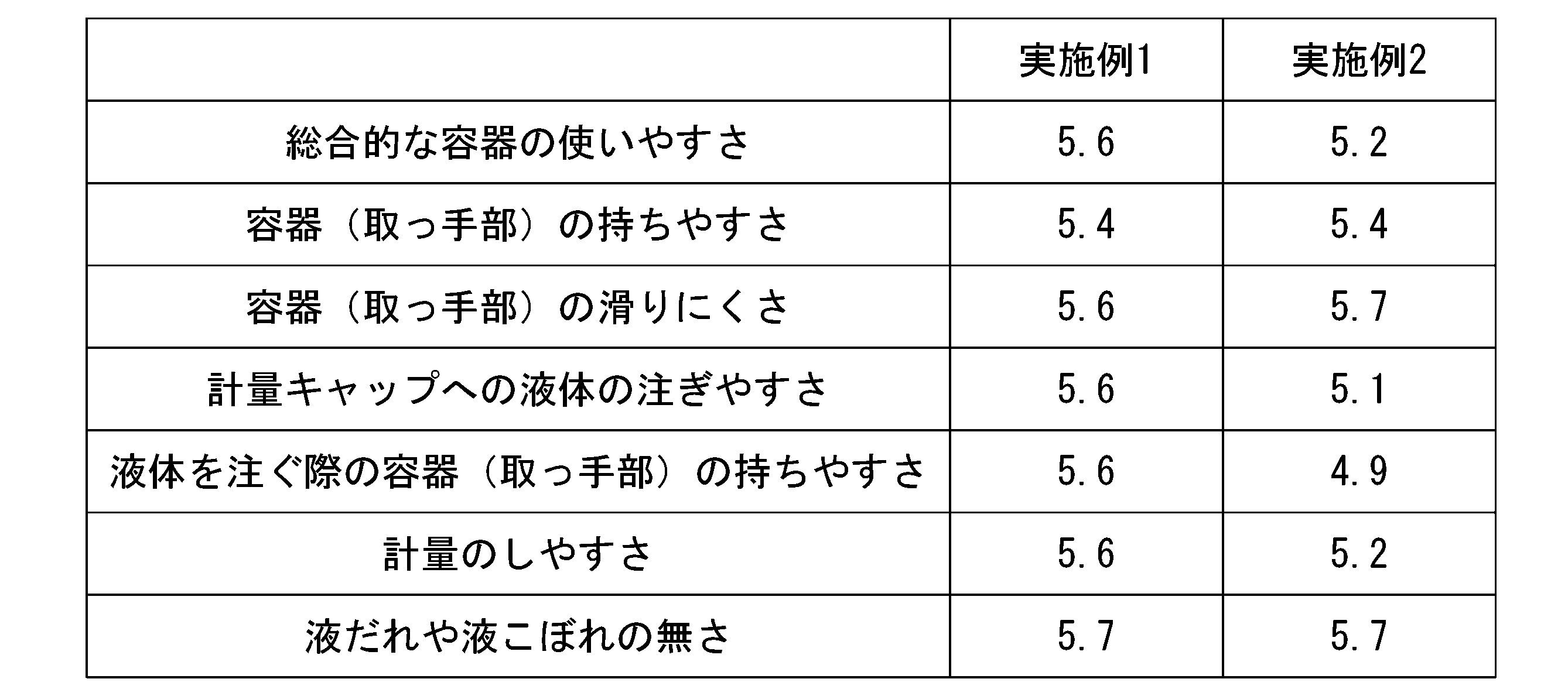
[表1]に示されるように、実施例1のサンプルおよび実施例2のサンプルのいずれについても、全ての評価項目で良好な評価が得られた。
モニターの傾注動作を観察すると、滑り止め部を認知した被験者は、実施例1のサンプルおよび実施例2のサンプルのいずれについても、容器を把持する際に親指を滑り止め部に設置するような把持姿勢であった。これは、両サンプルとも滑り止め部が非対向領域に設けられていることに加えて、空隙の上端よりも上側の位置に配置されているため、滑り止め部に対する視認性が高く、取っ手部を把持する際の把持位置を無意識に誘導できたと考えられる。
特に、実施例1のサンプルは、幅方向について滑り止め部の全てが台座部の端部からの距離D1が50mm以内に設けられ、高さ方向について滑り止め部の全てが台座部の端部からの距離D2が40mm以内に設けられる構成を有しており、滑り止め部に対する視認性が高いことから、把持位置をより好ましい位置に誘導することができる。その結果、実施例1のサンプルは、傾注動作に関する評価、使用性に関する評価でより良好な評価が得られた。
以上、添付図面を参照しながら本発明に係る好適な実施形態について説明したが、本発明は係る例に限定されないことは言うまでもない。上述した例において示した各構成部材の諸形状や組み合わせ等は一例であって、本発明の主旨から逸脱しない範囲において設計要求等に基づき種々変更可能である。
例えば、上記実施形態では、滑り止め部70の少なくとも一部が、台座部21の端部から幅方向の距離D1が50mm以内であり、台座部21の端部から高さ方向の距離D2が40mm以内の位置に設けられる構成を例示したが、この構成に限定されず、上記の範囲外のみに設けられる構成であってもよい。滑り止め部70が上記の範囲外のみに設けられる場合も、非対向領域60に位置していれば、容器本体2に視線を遮られることなく滑り止め部70を視認させやすくなり、取っ手部3を把持した際の滑りにくさを容易に喚起させることが可能になる。
また、上記実施形態では、滑り止め部70を外面61の一部のみ、または取っ手部3の全周に亘って設ける構成を例示したが、この構成に限定されず、例えば、側面62のみに設ける構成や、台座部21の端部から幅方向の距離D1が50mm以内であり、台座部21の端部から高さ方向の距離D2が40mm以内の範囲の全面に設ける構成であってもよい。
また、上記実施形態では、滑り止め部70が凸部71を有する構成を例示したが、滑り止め部70としては凸部71の他に凹部を有する構成や、凸部71と凹部とを組み合わせた構成であってもよい。
また、上記実施形態では、容器本体2と取っ手部3とが一体的な成形体である構成を例示したが、この構成に限られず、個別に製作された容器本体と取っ手部とを用い、取っ手部が容器本体に装着された容器であってもよい。この構成においても、容器本体に装着されたときに、取っ手部において容器本体に対して非対向となる領域に滑り止め部を設ければよい。
本発明は、容器に適用できる。
1…容器、 2…容器本体、 3…取っ手部、 4…突出部、 5…延出部、 6…空隙、 10…首部、 11…開口部、 21…台座部、 31C…側面(側部)、 50…対向領域、 60…非対向領域、 61…外面(面部)、 62…側面(面部)、 70…滑り止め部、 71…凸部
Claims (9)
- 正立状態で上下方向に延びる容器本体と、
前記容器本体に設けられ滑り止め部を有する取っ手部とを備え、
前記取っ手部は、前記容器本体と対向する対向領域と、前記容器本体と非対向の非対向領域とを有し、
前記非対向領域に前記滑り止め部が設けられていることを特徴とする容器。 - 前記取っ手部は、前記容器本体の側部から離れる方向に突出する突出部と、前記突出部の先端から下方に延出する延出部とを有し、
前記延出部は、前記容器本体との間に、開放された空隙を隔てて設けられ、
前記滑り止め部は、前記空隙の上端よりも上側の位置に配置されている、
請求項1に記載の容器。 - 前記延出部は、把持部を構成し、
前記空隙の上端よりも上側に位置する前記滑り止め部は、前記延出部を把持した際の指当て部を構成する、
請求項2に記載の容器。 - 前記容器本体は、前記上下方向と直交する断面が略矩形状であり、
前記取っ手部の前記突出部は、前記容器本体の側部のうち、前記断面において短辺となる側部から突出する、
請求項2または3に記載の容器。 - 前記非対向領域は、互いに交差する二つ以上の面部を有し、
前記滑り止め部は、前記二つ以上の面部に跨がって設けられている、
請求項1から4のいずれか一項に記載の容器。 - 前記容器本体は、上端に開口部を有する首部と、
前記首部が上側に突出する台座部とを有し、
前記滑り止め部は、前記台座部の端部から前記上下方向と直交する方向の距離が50mm以内であり、前記台座部の端部から上下方向の距離が40mm以内の位置に設けられている、
請求項1から5のいずれか一項に記載の容器。 - 前記容器本体は、内容物を収容する第1収容部を有し、
前記取っ手部は、前記内容物を収容する第2収容部を有し、
前記第2収容部は、前記第1収容部と連通する、
請求項1から6のいずれか一項に記載の容器。 - 前記滑り止め部は、前記上下方向と交差する方向に延び、前記上下方向に間隔をあけて複数設けられた凸部を有する、
請求項1から7のいずれか一項に記載の容器。 - 前記凸部は、前記取っ手部の前記交差する方向の中央から端部に向かうのに従って、幅および凸量が漸次小さくなっている、
請求項8に記載の容器。
Applications Claiming Priority (2)
| Application Number | Priority Date | Filing Date | Title |
|---|---|---|---|
| JP2020040316A JP2021138440A (ja) | 2020-03-09 | 2020-03-09 | 容器 |
| JP2020-040316 | 2020-03-09 |
Publications (1)
| Publication Number | Publication Date |
|---|---|
| WO2021182298A1 true WO2021182298A1 (ja) | 2021-09-16 |
Family
ID=77667633
Family Applications (1)
| Application Number | Title | Priority Date | Filing Date |
|---|---|---|---|
| PCT/JP2021/008463 Ceased WO2021182298A1 (ja) | 2020-03-09 | 2021-03-04 | 容器 |
Country Status (2)
| Country | Link |
|---|---|
| JP (1) | JP2021138440A (ja) |
| WO (1) | WO2021182298A1 (ja) |
Families Citing this family (1)
| Publication number | Priority date | Publication date | Assignee | Title |
|---|---|---|---|---|
| JP7699030B2 (ja) * | 2021-10-12 | 2025-06-26 | 住友化学園芸株式会社 | 液体容器 |
Citations (5)
| Publication number | Priority date | Publication date | Assignee | Title |
|---|---|---|---|---|
| US6049945A (en) * | 1998-12-17 | 2000-04-18 | Graham Packaging Company L.P. | Stackable ergonomic handle |
| JP2001146237A (ja) * | 1999-11-18 | 2001-05-29 | Lion Corp | 取っ手付き容器 |
| JP2006062732A (ja) * | 2004-08-30 | 2006-03-09 | Pigeon Corp | 飲料容器 |
| JP2006347580A (ja) * | 2005-06-15 | 2006-12-28 | Pigeon Corp | 飲料容器及び飲み口付蓋体 |
| US20130206764A1 (en) * | 2012-02-09 | 2013-08-15 | Kent M. ARNOLD | Mug and ambidextrous lid assembly |
-
2020
- 2020-03-09 JP JP2020040316A patent/JP2021138440A/ja active Pending
-
2021
- 2021-03-04 WO PCT/JP2021/008463 patent/WO2021182298A1/ja not_active Ceased
Patent Citations (5)
| Publication number | Priority date | Publication date | Assignee | Title |
|---|---|---|---|---|
| US6049945A (en) * | 1998-12-17 | 2000-04-18 | Graham Packaging Company L.P. | Stackable ergonomic handle |
| JP2001146237A (ja) * | 1999-11-18 | 2001-05-29 | Lion Corp | 取っ手付き容器 |
| JP2006062732A (ja) * | 2004-08-30 | 2006-03-09 | Pigeon Corp | 飲料容器 |
| JP2006347580A (ja) * | 2005-06-15 | 2006-12-28 | Pigeon Corp | 飲料容器及び飲み口付蓋体 |
| US20130206764A1 (en) * | 2012-02-09 | 2013-08-15 | Kent M. ARNOLD | Mug and ambidextrous lid assembly |
Also Published As
| Publication number | Publication date |
|---|---|
| JP2021138440A (ja) | 2021-09-16 |
Similar Documents
| Publication | Publication Date | Title |
|---|---|---|
| JP3134790U (ja) | ボトル容器 | |
| JP3426609B2 (ja) | 握持容易なボトル | |
| US8613563B2 (en) | Detergent dispensing and pre-treatment cap | |
| AU2010365822B2 (en) | Consumer packaging | |
| US20170240317A1 (en) | Bottle | |
| JP2021138440A (ja) | 容器 | |
| WO2012158316A1 (en) | Article with ergonomic integral handle | |
| JP6623523B2 (ja) | 液体用容器 | |
| JP2018039543A (ja) | ボトル容器 | |
| JP6192225B2 (ja) | 計量キャップ | |
| JP4931097B2 (ja) | キャップを開封しやすい形状を有するガラスびん | |
| US10279957B2 (en) | Container for liquid detergent and method for the metered dispensing of detergent from the container | |
| JP2012144280A (ja) | 計量キャップ | |
| US4690311A (en) | Bottle with finger pieces | |
| JP7670903B1 (ja) | 把持部を有する容器 | |
| JP7798567B2 (ja) | 計量キャップ | |
| JP2009107706A (ja) | ピンチグリップ式ボトル型容器 | |
| CN224159567U (zh) | 具有握持部的容器 | |
| JP5470012B2 (ja) | ボトル型容器 | |
| JP6933445B2 (ja) | 容器 | |
| JP5891066B2 (ja) | 合成樹脂製液体容器 | |
| JP3220424U (ja) | 容器蓋部 | |
| JP2019048669A (ja) | 液体用容器 | |
| CA2952693A1 (en) | Bottle for control of liquid contents | |
| AU2016277678A1 (en) | Bottle for control of liquid contents |
Legal Events
| Date | Code | Title | Description |
|---|---|---|---|
| 121 | Ep: the epo has been informed by wipo that ep was designated in this application |
Ref document number: 21767439 Country of ref document: EP Kind code of ref document: A1 |
|
| NENP | Non-entry into the national phase |
Ref country code: DE |
|
| 122 | Ep: pct application non-entry in european phase |
Ref document number: 21767439 Country of ref document: EP Kind code of ref document: A1 |