WO2021182226A1 - 軸ずれ検出装置、及び、軸ずれ検出プログラム - Google Patents
軸ずれ検出装置、及び、軸ずれ検出プログラム Download PDFInfo
- Publication number
- WO2021182226A1 WO2021182226A1 PCT/JP2021/008139 JP2021008139W WO2021182226A1 WO 2021182226 A1 WO2021182226 A1 WO 2021182226A1 JP 2021008139 W JP2021008139 W JP 2021008139W WO 2021182226 A1 WO2021182226 A1 WO 2021182226A1
- Authority
- WO
- WIPO (PCT)
- Prior art keywords
- vehicle
- axis
- deviation
- data
- traveling locus
- Prior art date
- Legal status (The legal status is an assumption and is not a legal conclusion. Google has not performed a legal analysis and makes no representation as to the accuracy of the status listed.)
- Ceased
Links
Images





Classifications
-
- G—PHYSICS
- G01—MEASURING; TESTING
- G01S—RADIO DIRECTION-FINDING; RADIO NAVIGATION; DETERMINING DISTANCE OR VELOCITY BY USE OF RADIO WAVES; LOCATING OR PRESENCE-DETECTING BY USE OF THE REFLECTION OR RERADIATION OF RADIO WAVES; ANALOGOUS ARRANGEMENTS USING OTHER WAVES
- G01S13/00—Systems using the reflection or reradiation of radio waves, e.g. radar systems; Analogous systems using reflection or reradiation of waves whose nature or wavelength is irrelevant or unspecified
- G01S13/88—Radar or analogous systems specially adapted for specific applications
- G01S13/93—Radar or analogous systems specially adapted for specific applications for anti-collision purposes
- G01S13/931—Radar or analogous systems specially adapted for specific applications for anti-collision purposes of land vehicles
-
- B—PERFORMING OPERATIONS; TRANSPORTING
- B60—VEHICLES IN GENERAL
- B60W—CONJOINT CONTROL OF VEHICLE SUB-UNITS OF DIFFERENT TYPE OR DIFFERENT FUNCTION; CONTROL SYSTEMS SPECIALLY ADAPTED FOR HYBRID VEHICLES; ROAD VEHICLE DRIVE CONTROL SYSTEMS FOR PURPOSES NOT RELATED TO THE CONTROL OF A PARTICULAR SUB-UNIT
- B60W30/00—Purposes of road vehicle drive control systems not related to the control of a particular sub-unit, e.g. of systems using conjoint control of vehicle sub-units
- B60W30/10—Path keeping
-
- G—PHYSICS
- G01—MEASURING; TESTING
- G01S—RADIO DIRECTION-FINDING; RADIO NAVIGATION; DETERMINING DISTANCE OR VELOCITY BY USE OF RADIO WAVES; LOCATING OR PRESENCE-DETECTING BY USE OF THE REFLECTION OR RERADIATION OF RADIO WAVES; ANALOGOUS ARRANGEMENTS USING OTHER WAVES
- G01S13/00—Systems using the reflection or reradiation of radio waves, e.g. radar systems; Analogous systems using reflection or reradiation of waves whose nature or wavelength is irrelevant or unspecified
- G01S13/66—Radar-tracking systems; Analogous systems
- G01S13/68—Radar-tracking systems; Analogous systems for angle tracking only
-
- G—PHYSICS
- G01—MEASURING; TESTING
- G01S—RADIO DIRECTION-FINDING; RADIO NAVIGATION; DETERMINING DISTANCE OR VELOCITY BY USE OF RADIO WAVES; LOCATING OR PRESENCE-DETECTING BY USE OF THE REFLECTION OR RERADIATION OF RADIO WAVES; ANALOGOUS ARRANGEMENTS USING OTHER WAVES
- G01S7/00—Details of systems according to groups G01S13/00, G01S15/00, G01S17/00
- G01S7/02—Details of systems according to groups G01S13/00, G01S15/00, G01S17/00 of systems according to group G01S13/00
- G01S7/40—Means for monitoring or calibrating
- G01S7/4004—Means for monitoring or calibrating of parts of a radar system
- G01S7/4026—Antenna boresight
- G01S7/403—Antenna boresight in azimuth, i.e. in the horizontal plane
-
- G—PHYSICS
- G01—MEASURING; TESTING
- G01S—RADIO DIRECTION-FINDING; RADIO NAVIGATION; DETERMINING DISTANCE OR VELOCITY BY USE OF RADIO WAVES; LOCATING OR PRESENCE-DETECTING BY USE OF THE REFLECTION OR RERADIATION OF RADIO WAVES; ANALOGOUS ARRANGEMENTS USING OTHER WAVES
- G01S7/00—Details of systems according to groups G01S13/00, G01S15/00, G01S17/00
- G01S7/02—Details of systems according to groups G01S13/00, G01S15/00, G01S17/00 of systems according to group G01S13/00
- G01S7/40—Means for monitoring or calibrating
- G01S7/4052—Means for monitoring or calibrating by simulation of echoes
- G01S7/4082—Means for monitoring or calibrating by simulation of echoes using externally generated reference signals, e.g. via remote reflector or transponder
- G01S7/4091—Means for monitoring or calibrating by simulation of echoes using externally generated reference signals, e.g. via remote reflector or transponder during normal radar operation
-
- G—PHYSICS
- G01—MEASURING; TESTING
- G01S—RADIO DIRECTION-FINDING; RADIO NAVIGATION; DETERMINING DISTANCE OR VELOCITY BY USE OF RADIO WAVES; LOCATING OR PRESENCE-DETECTING BY USE OF THE REFLECTION OR RERADIATION OF RADIO WAVES; ANALOGOUS ARRANGEMENTS USING OTHER WAVES
- G01S7/00—Details of systems according to groups G01S13/00, G01S15/00, G01S17/00
- G01S7/02—Details of systems according to groups G01S13/00, G01S15/00, G01S17/00 of systems according to group G01S13/00
- G01S7/41—Details of systems according to groups G01S13/00, G01S15/00, G01S17/00 of systems according to group G01S13/00 using analysis of echo signal for target characterisation; Target signature; Target cross-section
- G01S7/417—Details of systems according to groups G01S13/00, G01S15/00, G01S17/00 of systems according to group G01S13/00 using analysis of echo signal for target characterisation; Target signature; Target cross-section involving the use of neural networks
-
- G—PHYSICS
- G08—SIGNALLING
- G08G—TRAFFIC CONTROL SYSTEMS
- G08G1/00—Traffic control systems for road vehicles
- G08G1/16—Anti-collision systems
-
- G—PHYSICS
- G01—MEASURING; TESTING
- G01S—RADIO DIRECTION-FINDING; RADIO NAVIGATION; DETERMINING DISTANCE OR VELOCITY BY USE OF RADIO WAVES; LOCATING OR PRESENCE-DETECTING BY USE OF THE REFLECTION OR RERADIATION OF RADIO WAVES; ANALOGOUS ARRANGEMENTS USING OTHER WAVES
- G01S13/00—Systems using the reflection or reradiation of radio waves, e.g. radar systems; Analogous systems using reflection or reradiation of waves whose nature or wavelength is irrelevant or unspecified
- G01S13/88—Radar or analogous systems specially adapted for specific applications
- G01S13/93—Radar or analogous systems specially adapted for specific applications for anti-collision purposes
- G01S13/931—Radar or analogous systems specially adapted for specific applications for anti-collision purposes of land vehicles
- G01S2013/9327—Sensor installation details
- G01S2013/93271—Sensor installation details in the front of the vehicles
Definitions
- the present disclosure relates to an axis deviation detecting device and the like for detecting a deviation of the central axis in an in-vehicle measuring device using radar waves.
- Patent Document 1 discloses a technique for detecting a deflection (in other words, axis deviation) of the central axis of the central axis in the front-rear direction of the vehicle in such a detection device.
- Patent Document 1 may not be able to accurately detect the shaft deviation depending on the traveling locus of the vehicle. That is, for example, when the yaw of the vehicle becomes large, an error may occur in the detection result of the position and the speed of the stopped obstacle, and as a result, the axis deviation may not be detected accurately.
- One aspect of the present disclosure is to provide a technique for improving the detection accuracy of axis deviation in an in-vehicle measuring device using radar waves.
- the axis deviation detection device is configured to detect the deviation of the central axis in an in-vehicle measuring device.
- the measuring device irradiates the radar wave while changing the irradiation direction over a predetermined angle on both sides of the central axis, and measures the stopped object by detecting the reflected wave of the radar wave.
- the axis misalignment detection device includes a correction unit, a generation unit, a determination unit, and a detection unit.
- the correction unit corrects the data obtained by the measurement by the measuring device by a method corresponding to the case where the traveling locus of the vehicle on which the measuring apparatus is mounted is a predetermined specific traveling locus, and corrects the position of the stopped object and / Alternatively, it is configured to generate first data indicating a value for speed.
- the generation unit generates second data indicating values related to the position and / or speed of the stopped object based on the behavior of the vehicle measured by the sensor unit, which is a part different from the part that irradiates the radar wave and detects the reflected wave. Configured to generate.
- the determination unit is configured to determine whether or not the travel locus of the vehicle is a specific travel locus.
- the detection unit is the first data based on the measurement performed by the measuring device when the determination unit determines that the traveling locus of the vehicle is the specific traveling locus, and the first data based on the measurement performed by the sensor unit in that case. It is configured to detect the deviation of the central axis by comparing with the two data.
- Two data are used.
- the correction is performed by a method corresponding to the specific traveling locus, whereby the error caused by the traveling of the vehicle along the specific traveling locus is suppressed. Therefore, the deviation of the central axis is detected by using the first data whose accuracy is improved by the correction. Therefore, it is possible to improve the detection accuracy of the axis deviation in the in-vehicle measuring device using the radar wave.
- the vehicle-mounted measuring device 1 of the present embodiment is configured to measure the position and / or speed of an object existing in front of the vehicle (hereinafter, own vehicle) on which the measuring device 1 is mounted (FIG.). 1).
- the measuring device 1 can perform measurement on one object, or can measure each of a plurality of objects in parallel.
- the object is a moving body or a stationary object, and the measuring device 1 measures the relative position and relative speed of the object with respect to the own vehicle.
- the measuring device 1 includes a control unit 10, a radar device 20, and a sensor unit 30.
- the control unit 10 is a portion that controls the measuring device 1 in an integrated manner, and includes a CPU 11, a microcomputer having a semiconductor memory such as a RAM, a ROM, and a flash memory (hereinafter referred to as a memory 12), and a communication unit 13. ..
- the CPU 11 executes the program stored in the memory 12.
- Each function of the measuring device 1 is realized by the CPU 11 executing the axis deviation detection program stored in the non-transitional substantive storage medium.
- the memory 12 corresponds to a non-transitional substantive storage medium in which the axis misalignment detection program is stored. Further, when the axis misalignment detection program is executed, the method corresponding to the axis misalignment detection program is executed.
- the measuring device 1 may include one microcomputer or a plurality of microcomputers. Further, the method for realizing the function of the measuring device 1 is not limited to software, and some or all of the functions may be realized by using an electronic circuit. In this case, the electronic circuit may be configured as a digital circuit, an analog circuit, or a combination thereof.
- the communication unit 13 is connected to a communication line such as an in-vehicle LAN (not shown) and communicates with other in-vehicle devices.
- the in-vehicle LAN may be, for example, one compliant with CAN (registered trademark).
- the measuring device 1 provides the measurement result of the object to, for example, an in-vehicle device for driving support or automatic driving via the in-vehicle LAN.
- the radar device 20 is mounted on the front side of the own vehicle 50, irradiates the irradiation region 60 extending in a fan shape in front of the own vehicle 50 with the radar wave, and receives the reflected wave of the irradiated radar wave to be an object. Measure the position and / or speed of (see FIG. 2). That is, the radar device 20 irradiates the radar wave while shifting the irradiation direction over the central angle 61 of the irradiation region 60 along the vehicle width direction of the own vehicle 50.
- the straight line passing through the center of the irradiation region 60 is referred to as the central axis 62.
- the central axis 62 may pass through the center of the irradiation region 60 so as to evenly divide the central angle 61 of the irradiation region 60 into two.
- the central axis 62 may be located on the right side or the left side of the center of the irradiation area 60.
- the central axis is defined as the y-axis
- the axis orthogonal to the central axis is defined as the x-axis.
- the radar device 20 is mounted on the own vehicle 50 so that the central axis 62 (in other words, the y-axis) coincides with the front-rear direction of the own vehicle 50.
- the central axis 62 of the radar device 20 may be referred to as an axial deviation amount or ⁇ gap .
- the radar device 20 may be, for example, a so-called millimeter-wave radar that uses an electromagnetic wave in the millimeter-wave band as a radar wave, a laser radar that uses laser light as a radar wave, or a radar wave. It may be a sonar that uses sound waves.
- the sensor unit 30 is a part different from the radar device 20, and includes at least one sensor that detects the behavior of the own vehicle 50.
- the sensor unit 30 has a vehicle speed sensor 31 for measuring the vehicle speed (hereinafter, also referred to as V) and a yaw rate sensor 32 for measuring the yaw rate (hereinafter, also referred to as ⁇ ).
- V vehicle speed
- ⁇ yaw rate
- the yaw rate and the vehicle speed measured by the vehicle speed sensor 31 are also referred to as odometry information.
- the sensor unit 30 may detect the behavior of the own vehicle 50 other than the yaw rate or the vehicle speed.
- the control unit 10 of the measuring device 1 relates to the position and / or velocity of the object by tracking the object with an ⁇ tracker using a constant velocity linear motion model based on the data generated by the radar device 20 in the Tms cycle. Make a measurement.
- the control unit 10 may perform measurement using, for example, an ⁇ tracker using another motion model, or may perform measurement using a tracking filter (for example, a Kalman filter) other than the ⁇ tracker.
- the measuring device 1 has a function as an axis deviation detecting device 1 for detecting the above-mentioned axis deviation.
- the axis deviation is detected by using the measurement data (hereinafter referred to as the first measurement data) relating to the position and / or speed of the stopped object obtained by the measurement by the measuring device 1.
- the data showing the behavior of the own vehicle 50 obtained by the measurement by the sensor unit 30 is referred to as the second measurement data.
- the control unit 10 is based on the first and second measurement data obtained by the measurement performed when the travel locus of the own vehicle 50 is a predetermined specific travel locus (hereinafter, also referred to as a specific travel period). Detects misalignment.
- the control unit 10 corrects the first measurement data by a method corresponding to the case where the traveling locus of the own vehicle 50 is a specific traveling locus, and indicates a value related to the position and / or speed of the stopped object. 1 Generate data. Further, the control unit 10 generates second data indicating a value relating to the position and / or speed of the stopped object based on the second measurement data. Then, the control unit 10 detects the axis deviation by comparing the first data and the second data.
- the specific traveling locus is, for example, a curve having a radius of curvature in a predetermined range and curving in the same direction.
- the first and second data show, as an example, an angle (hereinafter, also referred to as a vector angle) of the relative movement direction of the stopped object with respect to the own vehicle 50 with respect to the y-axis. Note that ⁇ 1 and ⁇ 2 in FIGS. 7 and 8 correspond to vector angles. However, the first and second data may show values other than the vector angle.
- the control unit 10 controls the radar device 20 and measures the position and / or speed of each of at least one object in front of the own vehicle 50 to obtain the first measurement data for each object. Specifically, the control unit 10 performs object tracking by the ⁇ tracker based on the vehicle speed and yaw rate of the own vehicle 50 newly obtained by the sensor unit 30 and the data obtained from the radar device 20. As a result, for each of the at least one stop objects in front of the own vehicle 50, the position (s x , sy ) in the xy coordinate plane in front of the own vehicle 50 and the velocity vector relative to the own vehicle 50 (v x , v). The first measurement data indicating y) is generated.
- the control unit 10 based on the velocity vector measured over a period of time (v x, v y), calculates the position of the stationary object (s x, s y), using the calculated positions Therefore, the axis deviation may be detected by the subsequent processing. Further, for example, only the position of the stopped object (s x , sy ) may be measured as the first measurement data.
- control unit 10 the measured position over time (s x, s y) based on the velocity vector (v x, v y) of the stationary objects is calculated, the calculated velocity vector It may be used to detect the axis deviation by the subsequent processing.
- the control unit 10 measures the vehicle speed and yaw rate of the own vehicle 50 by the sensor unit 30. Then, the control unit 10 calculates ⁇ x and ⁇ y based on the vehicle speed. Note that ⁇ x and ⁇ y are distances that the own vehicle 50 is displaced in the x-axis direction and the y-axis direction from the time point before Tms to the present time, respectively. Further, the control unit 10 calculates ⁇ based on the yaw rate. Note that ⁇ is an angle at which the own vehicle 50 is rotationally displaced along the traveling locus from the time point before Tms to the present time. That is, S105 calculates ⁇ x, ⁇ y, and ⁇ in the Tms cycle, and by accumulating these, the traveling locus of the own vehicle 50 in the pre-learning period is formed (see FIG. 4).
- control unit 10 executes the axis deviation amount calculation process based on the measurement result in S100. As a result, the amount of axial deviation ⁇ gap is calculated corresponding to each of at least one stopped object.
- control unit 10 adds the sum of the ⁇ gaps newly calculated in the axis deviation amount calculation process to the pre-learning value sum by the following equation (1). This updates the sum in the current pre-learning period.
- the number m of the stopped object (m is an integer of 1 or more) for which the amount of axial deviation is newly calculated by the following equation (2) is added to the number of detections M of the amount of axial deviation of the stopped object in the current pre-learning period. Will be done.
- the control unit 10 determines whether or not the current pre-learning period has ended. Specifically, it is determined whether or not a predetermined time T pre (for example, 10 s) has elapsed after the start of the current pre-learning period. Then, the control unit 10 shifts to S125 when an affirmative determination is obtained (S120: Yes), and ends this process when a negative determination is obtained (S120: No).
- T pre for example, 10 s
- the control unit 10 travels in the current pre-learning period by using ⁇ x 0 to ⁇ x I and ⁇ y 0 to ⁇ y I calculated based on the odometry information obtained in the pre-learning period and ⁇ 0 to ⁇ I. It is determined whether or not the locus is a specific traveling locus (see FIG. 4). Specifically, the control unit 10 calculates the rotation angle ⁇ of the own vehicle 50 in the pre-learning period by the following equation (3).
- the average angular velocity ⁇ pre of the own vehicle 50 in the current pre-learning period is expressed by the equation (4).
- the radius of curvature R in the traveling locus during the pre-learning period is expressed by the following equation (5) based on the average vehicle speed Ave of the own vehicle 50 in the current pre-learning period.
- the radius of curvature R is expressed by the following equation (6).
- the radius of curvature R is expressed by the equation (7).
- positions X and Y of the own vehicle 50 at the end of the current pre-learning period are calculated by the following equations (8) and (9) based on ⁇ x i and ⁇ y i, respectively.
- the control unit 10 calculates the radius of curvature R by the equations (7) to (9) based on the rotation angle ⁇ of the own vehicle 50 and ⁇ x 0 to ⁇ x I and ⁇ y 0 to ⁇ y I. Then, the control unit 10 determines whether or not R is within a predetermined range. Then, when the affirmative determination is obtained (S125: Yes), the control unit 10 considers that the traveling locus in the current pre-learning period is the specific traveling locus, shifts to S130, and obtains a negative determination. If so (S125: No), the process proceeds to S135.
- the control unit 10 may determine whether or not the traveling locus of the own vehicle 50 during the pre-learning period is a specific traveling locus based on information indicating the behavior of the own vehicle 50 other than the yaw rate and the vehicle speed.
- control unit 10 updates the SUM by adding the pre-learning value sum of the axial deviation amount to the SUM which is the sum of the axial deviation amounts in the specific traveling period by the following equation (10).
- control unit 10 adds the number of times M of the amount of shaft deviation detected in the pre-learning period to the total number of times N of detection of the amount of shaft deviation in the specific traveling period by the following equation (11).
- control unit 10 calculates GAP, which is an average value of the amount of axial deviation based on the measurement result for the stopped object, by the following equation (12).
- control unit 10 may consider that an error occurs in the measurement of the object using the radar device 20 due to the influence of the axis deviation. Further, in this case, the control unit 10 may correct the measurement data of the object using the radar device 20 based on the GAP.
- control unit 10 ends the axis misalignment detection process.
- control unit 10 discards the pre-learning value sum calculated in the current pre-learning period, and ends the axis deviation detection process without adding sum to the learning value SUM.
- control unit 10 initializes the pre-learning value sum of the axis deviation amount and the detection number M of the axis deviation amount in the pre-learning period.
- the control unit 10 determines whether or not a stationary object is included in the object measured in S100 of the axis deviation detection process. Specifically, for example, the control unit 10 compares the velocity vector of each object measured in S100 with the velocity vector of the own vehicle 50 calculated from the odometry information, so that each object is a stationary object. It may be determined whether or not there is. Then, when a negative determination is obtained (S200: No), the control unit 10 ends this process. On the other hand, when the affirmative determination is obtained (S200: Yes), the control unit 10 executes S205 to 220 in order to calculate the amount of axial deviation of all the stopped objects measured in S100. That is, the processing of S205 to 220 is performed for each stopped object on which the measurement has been performed.
- control unit 10 calculates the correction value of the steady-state error included in the velocity vector of the measured stationary objects in S100 (v x, v y) .
- the steady-state error is caused by the motion model of the ⁇ tracker being a constant velocity linear motion model.
- centripetal acceleration a is a relative acceleration with respect to the own vehicle 50. Therefore, when tracking a stopped object with an ⁇ tracker using a constant velocity linear motion model, a stationary error occurs due to the centripetal acceleration a, and the measurement accuracy of the velocity vector is lowered.
- the control unit 10 calculates the steady-state error based on the constants ⁇ and ⁇ in the ⁇ tracker, and calculates the correction value of the velocity vector.
- the control unit 10 by the following equation (13), the position of the stationary object 70 obtained in S100 of the axis deviation detecting operation (s x, s y) and was calculated based on the odometry information ⁇ 0 is calculated based on the radius of curvature R of the specific traveling locus.
- ⁇ 0 is an angle formed by a straight line connecting the center of the specific traveling locus, which is a curve, and the own vehicle, and a straight line connecting the center and the position (s x , sy) of the stopped object 70.
- control unit 10 calculates the centripetal acceleration a based on the yaw rate ⁇ , which is odometry information, and the radius of curvature R, according to the following equation (14).
- the control unit 10 has the following formula (15) and (16), calculates the x-axis direction component a x of the centripetal acceleration a, and a y-axis direction component a y.
- T in the equation (17) corresponds to the cycle in which the object is tracked by the ⁇ tracker (in other words, the cycle of the axis misalignment detection process).
- the x-axis direction components and y-axis direction components of the constants ⁇ and ⁇ in the ⁇ tracker are ⁇ x , ⁇ y , ⁇ x , and ⁇ y , respectively.
- control unit 10 has the following formula (18) and (19), calculates a correction value ve x the steady error of the velocity v x of the x-axis direction of the stationary object 70 when the centripetal acceleration a is generated ..
- the control unit 10 has the following formula (20) and (21), calculates a correction value ve y of steady-state error of the velocity v y of the y-axis direction of the stationary object 70 when the centripetal acceleration a is generated ..
- control unit 10 based velocity vector (v x, v y) of the stationary object and the correction value ve x the steady error of the stationary object 70 when the centripetal acceleration a is generated in the ve y, below
- the vector angle ⁇ 1 is calculated by the equation (22) of (see FIG. 7).
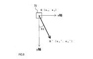
- the control unit 10 calculates the vector angle ⁇ 2 by performing an ego motion that predicts the behavior of the own vehicle 50 based on the odometry information (see FIG. 8). Specifically, the control unit 10 uses the following equation (23) based on ⁇ , ⁇ x and ⁇ y, and the position (s x , sy ) of the stopped object 70 to predict the vehicle position (s x ′). , S y ⁇ ) is calculated.
- control unit 10 calculates the vector angle ⁇ 2 by the following equation (24).
- the control unit 10 may calculate the vector angle ⁇ 2 based on the information indicating the behavior of the own vehicle 50 other than the yaw rate and the vehicle speed.
- control unit 10 calculates the amount of axial deviation ⁇ gap by the following equation (25).
- the ⁇ gap is calculated based on the measurement result of all the stopped objects obtained in S100. That is, when the measurement result of m stopped objects is obtained in S100, m ⁇ gaps are calculated by S205 to 220.
- the first data based on the first measurement data obtained by the radar wave when the own vehicle 50 is traveling along the specific traveling locus, and the sensor in that case.
- the second data based on the second measurement data obtained by the unit 30 is used.
- the first measurement data is corrected by a method corresponding to the specific traveling locus, and as a result, the error caused by the traveling of the own vehicle 50 along the specific traveling locus is performed. Is suppressed. Therefore, the deviation of the central axis 62 is detected by using the first data whose accuracy is improved by the correction. Therefore, the accuracy of detecting the axis deviation in the measuring device 1 can be improved.
- the first and second data show the vector angle. Then, the axis deviation amount ⁇ gap is calculated from the difference between the vector angle ⁇ 1 indicated by the first data and the vector angle ⁇ 2 indicated by the second data. Therefore, the amount of misalignment can be suitably detected.
- the specific traveling locus is a curve having a radius of curvature R in a predetermined range, and is steady based on the centripetal acceleration a generated in the stopped object 70 when the own vehicle 50 travels on the curve.
- correction value ve x error, ve y are calculated.
- the velocity vector (v x , v y ) of the stationary object 70, which is the first measurement data is corrected by the correction value, and then the vector angle ⁇ 1 which is the first data is calculated. Therefore, for example, even when the own vehicle 50 travels at the entrance / exit of a curve and the yaw of the own vehicle 50 becomes large, the accuracy of detecting the amount of shaft deviation can be improved.
- the first measurement data is generated by tracking by ⁇ tracker, the correction value ve x, ve y of steady-state error is calculated on the basis of constant alpha, a ⁇ in ⁇ tracker. Therefore, the accuracy of the vector angle ⁇ 1 which is the first data can be improved.
- the second measurement data is data indicating the yaw rate and vehicle speed of the own vehicle 50. Therefore, the vector angle ⁇ 2, which is the second data, can be satisfactorily generated.
- the control unit 10 of the measuring device 1 corrects the first measurement data regarding the position and / or speed of the stopped object 70 by a method corresponding to the case where the traveling locus of the own vehicle 50 is a predetermined specific traveling locus. You may. Then, the control unit 10 may provide the corrected value as a measurement result regarding the position and / or speed of the stopped object 70.
- the control unit 10 corrects the steady-state error based on the speeds v x and v y measured for the stopped object 70 by the same processing as in S205.
- value ve x may be calculated ve y.
- the control unit 10 the speed v x by using the correction value, v the corrected value of y, may be calculated as the measurement result of the velocity of the stationary object 70.
- the control unit 10 for example, v x -ve x, a v y -ve y calculated as the measurement result of the velocity of the stationary object 70, performs the measurement results, for example, the driving support or automatic operation It may be provided to the device.
- the own vehicle 50 is traveling along a specific traveling locus, the measurement accuracy of the stopped object 70 can be improved.
- the axis misalignment detection device 1 is configured as a part of the measurement device 1 that uses radar waves.
- the axis misalignment detection device 1 may be configured as a device different from the measuring device 1. Even in such a case, the axis deviation detecting device can detect the axis deviation in the same manner by acquiring the first measurement data or the like from the measuring device 1.
- the specific traveling locus is a curve, but for example, a linearly extending locus may be used as the specific traveling locus.
- the axis misalignment detection device 1 corrects the first measurement data by a method corresponding to the specific traveling locus extending linearly to generate the first data, as in the above embodiment, and generates the first data, and the first data and the second data.
- the axis deviation may be detected by comparing with.
- a plurality of functions possessed by one component in the above embodiment may be realized by a plurality of components, or one function possessed by one component may be realized by a plurality of components. .. Further, a plurality of functions possessed by the plurality of components may be realized by one component, or one function realized by the plurality of components may be realized by one component. Further, a part of the configuration of the above embodiment may be omitted. In addition, at least a part of the configuration of the above embodiment may be added or replaced with the configuration of the other above embodiment.
- the axis deviation detection program used in the control unit 10 of the axis deviation detection device 1 may be stored in a computer-readable non-transition tangible recording medium as an instruction executed by a computer.
Landscapes
- Engineering & Computer Science (AREA)
- Radar, Positioning & Navigation (AREA)
- Remote Sensing (AREA)
- Physics & Mathematics (AREA)
- General Physics & Mathematics (AREA)
- Computer Networks & Wireless Communication (AREA)
- Electromagnetism (AREA)
- Artificial Intelligence (AREA)
- Automation & Control Theory (AREA)
- Transportation (AREA)
- Mechanical Engineering (AREA)
- Evolutionary Computation (AREA)
- Radar Systems Or Details Thereof (AREA)
- Traffic Control Systems (AREA)
- Control Of Driving Devices And Active Controlling Of Vehicle (AREA)
Abstract
軸ずれ検出装置(1)は、車両に搭載され、レーダ波により測定を行う測定装置(1)の中心軸(62)のずれを検出する。軸ずれ検出装置(1)は、測定装置(1)により得られたデータを補正し、第1データを生成する。また、軸ずれ検出装置(1)は、センサ部(30)により測定された車両の挙動に基づき、第2データを生成する。そして、軸ずれ検出装置(1)は、第1及び第2データにより、中心軸(62)のずれを検出する。
Description
本国際出願は、2020年3月11日に日本国特許庁に出願された日本国特許出願第2020-42049号に基づく優先権を主張するものであり、日本国特許出願第2020-42049号の全内容を本国際出願に参照により援用する。
本開示は、レーダ波を用いた車載用の測定装置における中心軸のずれを検出する軸ずれ検出装置等に関する。
車両に搭載され、車両の前後方向に延びる中心軸を中心として、車幅方向に所定角度にわたってレーダ波を照射することで、障害物の位置及び速度を検出する検出装置が知られている。また、特許文献1には、このような検出装置における中心軸の車両の前後方向に対する偏向(換言すれば、軸ずれ)を検出する技術が開示されている。
しかしながら、発明者の詳細な検討の結果、特許文献1に開示された技術では、車両の走行軌跡によっては、軸ずれを精度良く検出できなくなる恐れがあるという課題が見出された。つまり、例えば車両のヨーが大きくなる場合等には、停止している障害物についての位置及び速度の検出結果に誤差が生じ、その結果、軸ずれを精度良く検出できなくなる恐れがある。
本開示の1つの局面は、レーダ波を用いた車載用の測定装置における軸ずれの検出精度を向上させる技術を提供する。
本開示の1つの態様による軸ずれ検出装置は、車載用の測定装置における中心軸のずれを検出するよう構成されている。測定装置は、中心軸の両側にて所定の角度にわたって照射方向を変化させながらレーダ波を照射すると共に、レーダ波の反射波を検出することで、停止物の測定を行う。また、軸ずれ検出装置は、補正部と、生成部と、判定部と、検出部と、を備える。
補正部は、測定装置による測定により得られたデータを、測定装置が搭載された車両の走行軌跡が予め定められた特定走行軌跡である場合に対応する方法で補正し、停止物の位置及び/又は速度に関する値を示す第1データを生成するよう構成される。生成部は、レーダ波の照射及び反射波の検出を行う部位とは異なる部位であるセンサ部により測定された車両の挙動に基づき、停止物の位置及び/又は速度に関する値を示す第2データを生成するよう構成される。判定部は、車両の走行軌跡が特定走行軌跡か否かを判定するよう構成される。検出部は、判定部により車両の走行軌跡が特定走行軌跡であると判定された場合に測定装置により行われた測定に基づく第1データと、該場合にセンサ部により行われた測定に基づく第2データとを比較することで、中心軸のずれを検出するよう構成される。
上記構成によれば、中心軸のずれの検出には、車両が特定走行軌跡に沿って走行している場合のレーダ波による測定に基づく第1データと、該場合におけるセンサ部による測定に基づく第2データとが用いられる。そして、第1データを生成する際には、特定走行軌跡に対応する方法で補正が行われ、これにより、特定走行軌跡に沿った車両の走行により生じた誤差が抑制される。このため、該補正により精度が向上した第1データを用いて、中心軸のずれが検出される。したがって、レーダ波を用いた車載用の測定装置における軸ずれの検出精度を向上させることができる。
なお、コンピュータを上記軸ずれ検出装置として動作させる軸ずれ検出プログラムを構成しても良い。このような軸ずれ検出プログラムに従いコンピュータを動作させることで、同様の効果が得られる。
以下、図面を参照しながら、本開示の実施形態を説明する。
[1.構成]
本実施形態の車載用の測定装置1は、当該測定装置1が搭載された車両(以後、自車両)の前方に存在する物体の位置及び/又は速度に関する測定を行うよう構成されている(図1参照)。無論、測定装置1は、1つの物体についての測定を行うこともできるし、複数の物体の各々について、並行して測定を行うこともできる。また、物体とは移動体又は停止物であり、測定装置1は、物体の自車両に対する相対位置及び相対速度を測定する。測定装置1は、制御部10と、レーダ装置20と、センサ部30とを備える。
本実施形態の車載用の測定装置1は、当該測定装置1が搭載された車両(以後、自車両)の前方に存在する物体の位置及び/又は速度に関する測定を行うよう構成されている(図1参照)。無論、測定装置1は、1つの物体についての測定を行うこともできるし、複数の物体の各々について、並行して測定を行うこともできる。また、物体とは移動体又は停止物であり、測定装置1は、物体の自車両に対する相対位置及び相対速度を測定する。測定装置1は、制御部10と、レーダ装置20と、センサ部30とを備える。
制御部10は、測定装置1を統括制御する部位であり、CPU11と、RAM、ROM、フラッシュメモリ等の半導体メモリ(以後、メモリ12とする)とを有するマイクロコンピュータと、通信部13とを備える。
CPU11は、メモリ12に保存されているプログラムを実行する。CPU11が非遷移的実体的記憶媒体に格納された軸ずれ検出プログラムを実行することにより、測定装置1の各機能が実現される。本実施形態では、メモリ12が、軸ずれ検出プログラムを格納した非遷移的実体的記憶媒体に該当する。また、軸ずれ検出プログラムが実行されることで、当該軸ずれ検出プログラムに対応する方法が実行される。なお、測定装置1は、1つのマイクロコンピュータを備えても良いし、複数のマイクロコンピュータを備えても良い。また、測定装置1の機能を実現する手法はソフトウェアに限るものではなく、その一部又は全部の機能は、電子回路を用いて実現されても良い。この場合、電子回路は、デジタル回路、又は、アナログ回路、あるいはこれらの組み合わせとして構成されていても良い。
通信部13は、図示しない車内LAN等の通信ラインと接続され、他の車載装置と通信を行う。なお、車内LANとは、例えばCAN(登録商標)に準拠したものであっても良い。また、測定装置1は、車内LANを介して、物体についての測定結果を、例えば、運転支援又は自動運転を行うための車載装置等に提供する。
また、レーダ装置20は、自車両50の前側に搭載され、自車両50の前方における扇状に広がる照射領域60にレーダ波を照射すると共に、照射したレーダ波の反射波を受信することで、物体の位置及び/又は速度に関する測定を行う(図2参照)。つまり、レーダ装置20は、自車両50の車幅方向に沿って照射領域60の中心角61にわたって照射方向を変位させながら、レーダ波を照射する。
ここで、照射領域60の中心を通過する直線を、中心軸62と記載する。中心軸62は、照射領域60の中心角61を均等に2分割するように照射領域60の中央を通過しても良い。無論、これに限らず、中心軸62は、照射領域60の中央よりも右側又は左側に位置していても良い。また、中心軸をy軸、中心軸に直交する軸をx軸とする。これらのx軸及びy軸により、レーダ波の発生源を原点とするxy座標平面が形成される。
そして、レーダ装置20は、中心軸62(換言すれば、y軸)が自車両50の前後方向と一致するように、自車両50に搭載される。しかしながら、レーダ装置20の中心軸62と自車両50の前後方向との間には、ずれが存在する場合がある。以後、自車両50の前後方向に対する中心軸62の角度を、軸ずれ量又はθgapと記載する。
なお、レーダ装置20は、例えば、レーダ波としてミリ波帯の電磁波を使用するいわゆるミリ波レーダであっても良いし、レーダ波としてレーザ光を用いるレーザレーダであっても良いし、レーダ波として音波を用いるソナーであっても良い。
また、センサ部30は、レーダ装置20とは異なる部位であり、自車両50の挙動を検出する少なくとも1つのセンサを備える。本実施形態では、一例として、センサ部30は、車速(以後、Vとも記載)を測定する車速センサ31と、ヨーレート(以後、ωとも記載)を測定するヨーレートセンサ32とを有する。以後、車速センサ31により測定されたヨーレート及び車速を、オドメトリ情報とも記載する。また、センサ部30は、ヨーレート又は車速以外の自車両50の挙動を検出しても良い。
[2.処理の概要]
測定装置1の制御部10は、Tms周期で、レーダ装置20により生成されたデータに基づき、等速直線運動モデルを用いたαβトラッカにより物体追尾を行うことで、物体の位置及び/又は速度に関する測定を行う。無論、制御部10は、例えば、他の運動モデルを用いたαβトラッカにより測定を行っても良いし、αβトラッカ以外の追尾フィルタ(例えば、カルマンフィルタ)を用いて測定を行っても良い。
測定装置1の制御部10は、Tms周期で、レーダ装置20により生成されたデータに基づき、等速直線運動モデルを用いたαβトラッカにより物体追尾を行うことで、物体の位置及び/又は速度に関する測定を行う。無論、制御部10は、例えば、他の運動モデルを用いたαβトラッカにより測定を行っても良いし、αβトラッカ以外の追尾フィルタ(例えば、カルマンフィルタ)を用いて測定を行っても良い。
また、測定装置1は、上述した軸ずれを検出する軸ずれ検出装置1としての機能を有している。軸ずれの検出は、測定装置1による測定にて得られた、停止物の位置及び/又は速度に関する測定データ(以後、第1測定データ)を用いて行われる。また、センサ部30による測定で得られた自車両50の挙動を示すデータを、第2測定データとする。制御部10は、自車両50の走行軌跡が予め定められた特定走行軌跡である場合(以後、特定走行期間とも記載)に行われた測定により得られた第1及び第2測定データに基づき、軸ずれの検出を行う。
具体的には、制御部10は、自車両50の走行軌跡が特定走行軌跡である場合に対応する方法で、第1測定データを補正し、停止物の位置及び/又は速度に関する値を示す第1データを生成する。また、制御部10は、第2測定データに基づき、停止物の位置及び/又は速度に関する値を示す第2データを生成する。そして、制御部10は、第1データと第2データとを比較することで、軸ずれを検出する。
なお、本実施形態では、特定走行軌跡とは、一例として、予め定められた範囲の曲率半径を有し、同一方向に湾曲するカーブである。また、第1及び第2データは、一例として、自車両50に対する停止物の相対的な移動方向の、y軸に対する角度(以後、ベクトル角とも記載)を示す。なお、図7、8におけるθ1、θ2が、ベクトル角に相当する。しかしながら、第1及び第2データは、ベクトル角以外の値を示しても良い。
[3.軸ずれ検出処理]
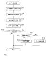
次に、測定装置1における軸ずれを検出する軸ずれ検出処理について説明する(図3参照)。本処理では、周期的に到来するプレ学習期間が設けられ、各プレ学習期間では、停止物の軸ずれ量の総和がプレ学習値sumとして算出される。そして、プレ学習期間における自車両の走行軌跡が特定走行軌跡である場合には、該プレ学習期間でのプレ学習値sumが、学習値SUMに加算される。つまり、SUMは、特定走行期間における停止物の軸ずれ量の総和に相当する。また、本処理は、自車両50の走行中に、軸ずれ検出装置1として機能する測定装置1の制御部10により、Tms間隔で周期的に実行される。
次に、測定装置1における軸ずれを検出する軸ずれ検出処理について説明する(図3参照)。本処理では、周期的に到来するプレ学習期間が設けられ、各プレ学習期間では、停止物の軸ずれ量の総和がプレ学習値sumとして算出される。そして、プレ学習期間における自車両の走行軌跡が特定走行軌跡である場合には、該プレ学習期間でのプレ学習値sumが、学習値SUMに加算される。つまり、SUMは、特定走行期間における停止物の軸ずれ量の総和に相当する。また、本処理は、自車両50の走行中に、軸ずれ検出装置1として機能する測定装置1の制御部10により、Tms間隔で周期的に実行される。
S100では、制御部10は、レーダ装置20を制御し、自車両50前方の少なくとも1つの物体の各々の位置及び/又は速度に関する測定を行うことで、各物体についての第1測定データを得る。具体的には、制御部10は、センサ部30により新たに得られた自車両50の車速及びヨーレートと、レーダ装置20から得られたデータに基づき、αβトラッカによる物体追尾を行う。これにより、自車両50前方の少なくとも1つの停止物の各々について、自車両50前方のxy座標平面における位置(sx、sy)と、自車両50に対する相対的な速度ベクトル(vx、vy)とを示す第1測定データが生成される。
なお、例えば、停止物の速度ベクトル(vx、vy)のみが、第1測定データとして測定されても良い。このような場合には、制御部10は、一定期間にわたって測定された速度ベクトル(vx、vy)に基づき、停止物の位置(sx、sy)を算出し、算出した位置を用いて、これ以降の処理により軸ずれを検出しても良い。また、例えば、停止物の位置(sx、sy)のみが、第1測定データとして測定されても良い。このような場合においても、制御部10は、一定期間にわたって測定された位置(sx、sy)に基づき、停止物の速度ベクトル(vx、vy)を算出し、算出した速度ベクトルを用いて、これ以降の処理により軸ずれを検出しても良い。
S105では、制御部10は、センサ部30により、自車両50の車速及びヨーレートを測定する。そして、制御部10は、車速に基づき、Δx及びΔyを算出する。なお、Δx、Δyとは、それぞれ、Tms前の時点から現時点までにおいて、自車両50がx軸方向、y軸方向に変位した距離である。また、制御部10は、ヨーレートに基づき、Δθを算出する。なお、Δθとは、Tms前の時点から現時点までにおいて、自車両50が走行軌跡に沿って回転変位した角度である。つまり、S105により、Tms周期でΔxとΔyとΔθとが算出され、これらを累積することで、プレ学習期間における自車両50の走行軌跡が形成される(図4参照)。
S110では、制御部10は、S100での測定結果に基づき、軸ずれ量算出処理を実行する。これにより、少なくとも1つの停止物の各々に対応して軸ずれ量θgapが算出される。
S115では、制御部10は、以下の式(1)により、軸ずれ量算出処理にて新たに算出されたθgapの総和を、プレ学習値sumに加算する。これにより、現在のプレ学習期間におけるsumが更新される。


S125では、制御部10は、プレ学習期間に得られたオドメトリ情報に基づき算出されたΔx0~ΔxI及びΔy0~ΔyIと、Δθ0~ΔθIとにより、現在のプレ学習期間の走行軌跡が特定走行軌跡であるか否かを判定する(図4参照)。具体的には、制御部10は、以下の式(3)により、プレ学習期間における自車両50の回転角度θを算出する。







S130では、制御部10は、以下の式(10)により、軸ずれ量のプレ学習値sumを、特定走行期間における軸ずれ量の総和であるSUMに加算することで、SUMを更新する。



そして、制御部10は、軸ずれ検出処理を終了する。
一方、S135では、制御部10は、現在のプレ学習期間に算出されたプレ学習値sumを破棄し、sumを学習値SUMに加算すること無く、軸ずれ検出処理を終了する。
そして、S130又はS135の終了後、次に軸ずれ検出処理が実行される際には、新たなプレ学習期間が開始される。このため、制御部10は、軸ずれ量のプレ学習値sumと、プレ学習期間における軸ずれ量の検出回数Mとを初期化する。
[4.軸ずれ量算出処理]
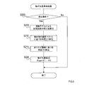
次に、レーダ装置20を用いた停止物の位置及び速度ベクトルの測定値に基づき軸ずれ量を算出する軸ずれ量算出処理について、図5のフローチャートを用いて説明する。本処理は、軸ずれ検出処理から実行されるサブルーチンとして構成されている。
次に、レーダ装置20を用いた停止物の位置及び速度ベクトルの測定値に基づき軸ずれ量を算出する軸ずれ量算出処理について、図5のフローチャートを用いて説明する。本処理は、軸ずれ検出処理から実行されるサブルーチンとして構成されている。
S200では、制御部10は、軸ずれ検出処理のS100で測定が行われた物体の中に、停止物が含まれているか否かを判定する。具体的には、例えば、制御部10は、S100にて測定された各物体の速度ベクトルと、オドメトリ情報から算出される自車両50の速度ベクトルとを比較することで、各物体が停止物であるか否かを判定しても良い。そして、制御部10は、否定判定が得られた場合には(S200:No)、本処理を終了する。一方、制御部10は、肯定判定が得られた場合には(S200:Yes)、S100で測定が行われた全ての停止物の軸ずれ量を算出するため、S205~220を実行する。つまり、S205~220の処理は、測定が行われた各停止物を対象として行われる。
S205では、制御部10は、S100で測定された停止物の速度ベクトル(vx、vy)に含まれる定常誤差の補正値を算出する。なお、該定常誤差は、αβトラッカの運動モデルが等速直線運動モデルであることに起因して生じる。
すなわち、カーブである特定走行軌跡に沿って自車両50が走行している場合には、停止物70には、カーブの中心に向かう向心加速度aが発生する(図6参照)。なお、向心加速度aは、自車両50に対する相対的な加速度である。このため、等速直線運動モデルを用いたαβトラッカにより停止物の追尾を行う際、向心加速度aにより定常誤差が生じ、速度ベクトルの測定精度が低下する。
しかし、測定の対象は停止物70であるため、向心加速度aの算出が可能である。また、物体の追尾にはαβトラッカが用いられているため、速度ベクトルにおける定常誤差を算出可能である。このため、制御部10は、αβトラッカにおける定数α、βに基づき該定常誤差を算出し、速度ベクトルの補正値を算出する。
具体的には、制御部10は、以下の式(13)により、軸ずれ検出処理のS100にて得られた停止物70の位置(sx、sy)と、オドメトリ情報に基づき算出された特定走行軌跡の曲率半径Rとに基づき、θ0を算出する。なお、θ0とは、カーブである特定走行軌跡の中心と自車両とを結ぶ直線と、該中心と停止物70の位置(sx、sy)とを結ぶ直線とがなす角度である。





そして、制御部10は、以下の式(18)、(19)により、向心加速度aが発生した場合における停止物70のx軸方向の速度vxの定常誤差の補正値vexを算出する。






S220では、制御部10は、以下の式(25)により、軸ずれ量θgapを算出する。

[1-3.効果]
上記実施形態によれば、以下の効果を奏する。
上記実施形態によれば、以下の効果を奏する。
(1)中心軸62のずれの検出には、自車両50が特定走行軌跡に沿って走行している場合にレーダ波により得られた第1測定データに基づく第1データと、該場合にセンサ部30により得られた第2測定データに基づく第2データとが用いられる。そして、第1データを生成する際には、特定走行軌跡に対応する方法で第1測定データの補正が行われており、これにより、特定走行軌跡に沿った自車両50の走行により生じた誤差が抑制される。このため、該補正により精度が向上した第1データを用いて、中心軸62のずれが検出される。したがって、測定装置1における軸ずれの検出精度を向上させることができる。
(2)また、第1及び第2データは、ベクトル角を示す。そして、第1データが示すベクトル角θ1と、第2データが示すベクトル角θ2との差分により、軸ずれ量θgapが算出される。このため、軸ずれ量を好適に検出できる。
(3)また、特定走行軌跡とは、予め定められた範囲の曲率半径Rを有するカーブであり、自車両50が該カーブを走行する際に停止物70に生じる向心加速度aに基づき、定常誤差の補正値vex、veyが算出される。そして、該補正値により第1測定データである停止物70の速度ベクトル(vx、vy)が補正された上で、第1データであるベクトル角θ1が算出される。このため、例えば、自車両50がカーブの出入口等を走行し、自車両50のヨーが大きくなった場合であっても、軸ずれ量の検出精度を向上させることができる。
(4)また、第1測定データは、αβトラッカによる追尾により生成され、定常誤差の補正値vex、veyは、αβトラッカにおける定数α、βに基づき算出される。このため、第1データであるベクトル角θ1の精度を向上させ得る。
(5)また、第2測定データは、自車両50のヨーレート及び車速を示すデータである。このため、第2データであるベクトル角θ2を、良好に生成できる。
[3.他の実施形態]
以上、本開示の実施形態について説明したが、本開示は上述の実施形態に限定されることなく、種々変形して実施することができる。
以上、本開示の実施形態について説明したが、本開示は上述の実施形態に限定されることなく、種々変形して実施することができる。
(1)上述した特許文献1に開示された技術では、例えば、車両がカーブ等を走行し、ヨーが大きくなる場合等には、停止物についての位置及び速度の測定結果に誤差が生じる可能性がある。このため、車両がカーブ等のような特定走行軌跡に沿って走行している場合において、停止物の測定精度を向上させるのが望ましい。
そこで、測定装置1の制御部10は、停止物70の位置及び/又は速度に関する第1測定データを、自車両50の走行軌跡が予め定められた特定走行軌跡である場合に対応する方法で補正しても良い。そして、制御部10は、該補正後の値を、停止物70の位置及び/又は速度に関する測定結果として提供しても良い。
つまり、制御部10は、自車両50が特定走行軌跡に沿って走行している場合、S205と同様の処理により、停止物70について測定された速度vx、vyに基づき、定常誤差の補正値vex、veyを算出しても良い。そして、制御部10は、該補正値を用いて速度vx、vyを補正した値を、停止物70の速度の測定結果として算出しても良い。具体的には、制御部10は、例えば、vx-vex、vy-veyを停止物70の速度の測定結果として算出し、該測定結果を、例えば、運転支援又は自動運転を行う装置に提供しても良い。
こうすることにより、自車両50が特定走行軌跡に沿って走行している場合に、停止物70の測定精度を向上させ得る。
(2)上記実施形態では、軸ずれ検出装置1は、レーダ波を用いる測定装置1の一部として構成されている。しかしながら、軸ずれ検出装置1は、測定装置1とは別の装置として構成されていても良い。このような場合であっても、軸ずれ検出装置は、測定装置1から第1測定データ等を取得することで、同様にして軸ずれを検出することができる。
(3)上記実施形態では、特定走行軌跡はカーブであるが、例えば、直線状に延びる軌跡を特定走行軌跡としても良い。そして、軸ずれ検出装置1は、上記実施形態と同様、直線状に延びる特定走行軌跡に対応する方法で第1測定データの補正を行って第1データを生成し、第1データと第2データとを比較することで、軸ずれを検出しても良い。
(4)上記実施形態における1つの構成要素が有する複数の機能を、複数の構成要素によって実現したり、1つの構成要素が有する1つの機能を、複数の構成要素によって実現したりしてもよい。また、複数の構成要素が有する複数の機能を、1つの構成要素によって実現したり、複数の構成要素によって実現される1つの機能を、1つの構成要素によって実現したりしてもよい。また、上記実施形態の構成の一部を省略してもよい。また、上記実施形態の構成の少なくとも一部を、他の上記実施形態の構成に対して付加又は置換してもよい。
(5)軸ずれ検出装置1の制御部10に用いられる軸ずれ検出プログラムは、コンピュータにより実行されるインストラクションとして、コンピュータ読み取り可能な非遷移有形記録媒体に記憶されても良い。
Claims (6)
- 中心軸(62)の両側にて所定の角度にわたって照射方向を変化させながらレーダ波を照射すると共に、前記レーダ波の反射波を検出することで、停止物(70)の測定を行う車載用の測定装置(1)における、前記中心軸のずれを検出するよう構成された軸ずれ検出装置(1)であって、
前記測定装置による測定により得られたデータを、前記測定装置が搭載された車両の走行軌跡が予め定められた特定走行軌跡である場合に対応する方法で補正し、前記停止物の位置及び/又は速度に関する値を示す第1データを生成するよう構成された補正部(S205、S210)と、
前記レーダ波の照射及び前記反射波の検出を行う部位とは異なる部位であるセンサ部(30)により測定された前記車両の挙動に基づき、前記停止物の位置及び/又は速度に関する値を示す第2データを生成するよう構成された生成部(S215)と、
前記車両の走行軌跡が前記特定走行軌跡か否かを判定するよう構成された判定部(S125)と、
前記判定部により前記車両の走行軌跡が前記特定走行軌跡であると判定された場合に前記測定装置により行われた測定に基づく前記第1データと、該場合に前記センサ部により行われた測定に基づく前記第2データとを比較することで、前記中心軸のずれを検出するよう構成された検出部(S130)と、
を備える軸ずれ検出装置。 - 請求項1に記載の軸ずれ検出装置において、
前記停止物の前記車両に対する相対的な速度の、前記車両の前後方向に対する角度を、ベクトル角(θ1、θ2)とし、
前記第1及び第2データは、前記ベクトル角を示す
軸ずれ検出装置。 - 請求項1又は請求項2に記載の軸ずれ検出装置において、
前記特定走行軌跡とは、予め定められた範囲の曲率半径(R)を有するカーブであり、
前記補正部は、前記特定走行軌跡に沿って走行する前記車両に対する前記停止物の相対的な向心加速度(a)に基づき、前記補正を行うよう構成されている
軸ずれ検出装置。 - 請求項1から請求項3のうちのいずれか1項に記載の軸ずれ検出装置において、
前記測定装置による測定は、αβトラッカにより行われ、
前記補正部は、前記αβトラッカにおける定数α及びβに基づき前記補正を行うよう構成されている
軸ずれ検出装置。 - 請求項1から請求項4のうちのいずれか1項に記載の軸ずれ検出装置において、
前記センサ部により、前記車両のヨーレート及び車速が測定される
軸ずれ検出装置。 - 中心軸(62)の両側にて所定の角度にわたって照射方向を変化させながらレーダ波を照射すると共に、前記レーダ波の反射波を検出することで、停止物(70)の測定を行う車載用の測定装置(1)における、前記中心軸のずれを検出するよう構成された軸ずれ検出装置(1)としてコンピュータを動作させる軸ずれ検出プログラムであって、
前記測定装置による測定により得られたデータを、前記測定装置が搭載された車両の走行軌跡が予め定められた特定走行軌跡である場合に対応する方法で補正し、前記停止物の位置及び/又は速度に関する値を示す第1データを生成するよう構成された補正部(S205、S210)と、
前記レーダ波の照射及び前記反射波の検出を行う部位とは異なる部位であるセンサ部(30)により測定された前記車両の挙動に基づき、前記停止物の位置及び/又は速度に関する値を示す第2データを生成するよう構成された生成部(S215)と、
前記車両の走行軌跡が前記特定走行軌跡か否かを判定するよう構成された判定部(S125)と、
前記判定部により前記車両の走行軌跡が前記特定走行軌跡であると判定された場合に前記測定装置により行われた測定に基づく前記第1データと、該場合に前記センサ部により行われた測定に基づく前記第2データとを比較することで、前記中心軸のずれを検出するよう構成された検出部(S130)と
してコンピュータを動作させる軸ずれ検出プログラム。
Priority Applications (1)
| Application Number | Priority Date | Filing Date | Title |
|---|---|---|---|
| US17/930,671 US12442916B2 (en) | 2020-03-11 | 2022-09-08 | Axis deviation detection device and axis deviation detection program |
Applications Claiming Priority (2)
| Application Number | Priority Date | Filing Date | Title |
|---|---|---|---|
| JP2020-042049 | 2020-03-11 | ||
| JP2020042049A JP7347275B2 (ja) | 2020-03-11 | 2020-03-11 | 軸ずれ検出装置、及び、軸ずれ検出プログラム |
Related Child Applications (1)
| Application Number | Title | Priority Date | Filing Date |
|---|---|---|---|
| US17/930,671 Continuation US12442916B2 (en) | 2020-03-11 | 2022-09-08 | Axis deviation detection device and axis deviation detection program |
Publications (1)
| Publication Number | Publication Date |
|---|---|
| WO2021182226A1 true WO2021182226A1 (ja) | 2021-09-16 |
Family
ID=77670702
Family Applications (1)
| Application Number | Title | Priority Date | Filing Date |
|---|---|---|---|
| PCT/JP2021/008139 Ceased WO2021182226A1 (ja) | 2020-03-11 | 2021-03-03 | 軸ずれ検出装置、及び、軸ずれ検出プログラム |
Country Status (3)
| Country | Link |
|---|---|
| US (1) | US12442916B2 (ja) |
| JP (1) | JP7347275B2 (ja) |
| WO (1) | WO2021182226A1 (ja) |
Families Citing this family (3)
| Publication number | Priority date | Publication date | Assignee | Title |
|---|---|---|---|---|
| US12077178B2 (en) * | 2019-08-02 | 2024-09-03 | Hitachi Astemo, Ltd. | Aiming device, driving control system, and method for calculating correction amount for sensor data |
| DE112022007306T5 (de) * | 2022-07-28 | 2025-04-10 | Hitachi Astemo, Ltd. | Radarvorrichtung und radarsignalverarbeitungsverfahren |
| CN116520265B (zh) * | 2023-04-27 | 2024-07-26 | 苏州承泰科技有限公司 | 毫米波雷达安装角度的校准方法、系统、设备及存储介质 |
Citations (4)
| Publication number | Priority date | Publication date | Assignee | Title |
|---|---|---|---|---|
| US5964822A (en) * | 1997-08-27 | 1999-10-12 | Delco Electronics Corp. | Automatic sensor azimuth alignment |
| JP2011220727A (ja) * | 2010-04-06 | 2011-11-04 | Mitsubishi Electric Corp | 予測装置及び予測システム及びコンピュータプログラム及び予測方法 |
| JP2011247721A (ja) * | 2010-05-26 | 2011-12-08 | Mitsubishi Electric Corp | 角速度推定装置及びコンピュータプログラム及び角速度推定方法 |
| WO2017104503A1 (ja) * | 2015-12-17 | 2017-06-22 | 株式会社デンソー | 移動体制御装置及び移動体制御方法 |
Family Cites Families (33)
| Publication number | Priority date | Publication date | Assignee | Title |
|---|---|---|---|---|
| JP3132361B2 (ja) * | 1995-03-17 | 2001-02-05 | トヨタ自動車株式会社 | 車載用レーダ装置 |
| JP3470453B2 (ja) * | 1995-04-06 | 2003-11-25 | 株式会社デンソー | 車間距離制御装置 |
| JP3331882B2 (ja) * | 1995-12-27 | 2002-10-07 | 株式会社デンソー | 車両用障害物検出装置の中心軸偏向量算出装置,中心軸偏向量補正装置,および車間制御装置 |
| US6025797A (en) * | 1997-07-22 | 2000-02-15 | Denso Corporation | Angular shift determining apparatus for determining angular shift of central axis of radar used in automotive obstacle detection system |
| JP4038944B2 (ja) | 1999-08-30 | 2008-01-30 | 株式会社デンソー | 車両用障害物検出装置の中心軸偏向量算出装置及び中心軸偏向量補正装置、操舵角中立学習装置並びに車間制御装置 |
| US6927699B2 (en) * | 2002-12-05 | 2005-08-09 | Denso Corporation | Object recognition apparatus for vehicle, and inter-vehicle distance control unit |
| JP4895484B2 (ja) * | 2004-06-28 | 2012-03-14 | 富士通テン株式会社 | 車載用レーダ装置の軸ずれ量演算方法及び車載用レーダ軸ずれ判定方法 |
| JP4428208B2 (ja) * | 2004-11-16 | 2010-03-10 | 株式会社デンソー | 車両用物体認識装置 |
| JP5618744B2 (ja) * | 2010-05-26 | 2014-11-05 | 三菱電機株式会社 | 道路形状推定装置及びコンピュータプログラム及び道路形状推定方法 |
| US20120173185A1 (en) * | 2010-12-30 | 2012-07-05 | Caterpillar Inc. | Systems and methods for evaluating range sensor calibration data |
| GB2490094B (en) * | 2011-03-29 | 2015-11-18 | Jaguar Land Rover Ltd | Monitoring apparatus and method |
| JP5912879B2 (ja) * | 2012-05-31 | 2016-04-27 | 株式会社デンソー | レーダ装置 |
| JP5926208B2 (ja) * | 2013-02-12 | 2016-05-25 | 株式会社デンソー | 車載レーダ装置 |
| JP5947279B2 (ja) * | 2013-12-20 | 2016-07-06 | 株式会社デンソー | 進路推定装置,及びプログラム |
| JP6321373B2 (ja) * | 2013-12-25 | 2018-05-09 | 株式会社デンソー | 進路推定装置,及びプログラム |
| CN109884618B (zh) * | 2014-02-20 | 2023-05-26 | 御眼视觉技术有限公司 | 车辆的导航系统、包括导航系统的车辆和导航车辆的方法 |
| US20160209211A1 (en) * | 2015-01-16 | 2016-07-21 | GM Global Technology Operations LLC | Method for determining misalignment of an object sensor |
| US20160223649A1 (en) * | 2015-01-30 | 2016-08-04 | Robert Bosch Gmbh | Systems and methods for radar vertical misalignment detection |
| CN111380545B (zh) * | 2015-02-10 | 2024-11-12 | 御眼视觉技术有限公司 | 用于自主车辆导航的方法、服务器、自主车辆以及介质 |
| JP6527369B2 (ja) * | 2015-03-31 | 2019-06-05 | 株式会社デンソー | 車両制御装置、及び車両制御方法 |
| JP6321576B2 (ja) * | 2015-05-12 | 2018-05-09 | トヨタ自動車株式会社 | 制限装置及び車両 |
| EP3104189B1 (en) * | 2015-06-11 | 2020-09-30 | Veoneer Sweden AB | Misalignment estimation for a vehicle radar system |
| CN106981710B (zh) * | 2016-01-15 | 2019-11-08 | 日本电产株式会社 | 波导装置、天线装置以及雷达 |
| DE102016204011A1 (de) * | 2016-03-11 | 2017-09-14 | Robert Bosch Gmbh | Vorrichtung zur Ermittlung einer Dejustage einer an einem Fahrzeug befestigten Detektionseinrichtung |
| US11953599B2 (en) * | 2017-01-26 | 2024-04-09 | Mobileye Vision Technologies Ltd. | Vehicle navigation based on aligned image and LIDAR information |
| US10279807B2 (en) * | 2017-02-17 | 2019-05-07 | GM Global Technology Operations LLC | System and method for predicting a possible lane departure when driving a vehicle autonomously or semi-autonomously, and for taking a remedial action to prevent a lane departure |
| JP2018182742A (ja) * | 2017-04-14 | 2018-11-15 | 日本電産株式会社 | スロットアンテナアレイ |
| US10248129B2 (en) * | 2017-04-19 | 2019-04-02 | GM Global Technology Operations LLC | Pitch compensation for autonomous vehicles |
| EP3413083B1 (en) * | 2017-06-09 | 2020-03-11 | Veoneer Sweden AB | A vehicle system for detection of oncoming vehicles |
| JP7674056B2 (ja) * | 2017-06-14 | 2025-05-09 | モービルアイ ビジョン テクノロジーズ リミテッド | 自律走行に関する走行情報のフレームワークとバッチ調整との結合 |
| JP6930394B2 (ja) * | 2017-11-24 | 2021-09-01 | トヨタ自動車株式会社 | 物体認識装置 |
| US11047955B2 (en) * | 2018-07-06 | 2021-06-29 | Lyft, Inc. | Calibrating a radar antenna |
| KR102644368B1 (ko) * | 2018-09-06 | 2024-03-07 | 현대자동차주식회사 | 레이더 센서의 타겟 각도 오차 보정 방법과 이를 이용한 레이더 감지 장치 |
-
2020
- 2020-03-11 JP JP2020042049A patent/JP7347275B2/ja active Active
-
2021
- 2021-03-03 WO PCT/JP2021/008139 patent/WO2021182226A1/ja not_active Ceased
-
2022
- 2022-09-08 US US17/930,671 patent/US12442916B2/en active Active
Patent Citations (4)
| Publication number | Priority date | Publication date | Assignee | Title |
|---|---|---|---|---|
| US5964822A (en) * | 1997-08-27 | 1999-10-12 | Delco Electronics Corp. | Automatic sensor azimuth alignment |
| JP2011220727A (ja) * | 2010-04-06 | 2011-11-04 | Mitsubishi Electric Corp | 予測装置及び予測システム及びコンピュータプログラム及び予測方法 |
| JP2011247721A (ja) * | 2010-05-26 | 2011-12-08 | Mitsubishi Electric Corp | 角速度推定装置及びコンピュータプログラム及び角速度推定方法 |
| WO2017104503A1 (ja) * | 2015-12-17 | 2017-06-22 | 株式会社デンソー | 移動体制御装置及び移動体制御方法 |
Also Published As
| Publication number | Publication date |
|---|---|
| JP7347275B2 (ja) | 2023-09-20 |
| US20230003877A1 (en) | 2023-01-05 |
| US12442916B2 (en) | 2025-10-14 |
| JP2021143906A (ja) | 2021-09-24 |
Similar Documents
| Publication | Publication Date | Title |
|---|---|---|
| JP4706984B2 (ja) | 衝突推定装置及び衝突推定方法 | |
| WO2021182226A1 (ja) | 軸ずれ検出装置、及び、軸ずれ検出プログラム | |
| JP4869858B2 (ja) | 車両の走行制御システム | |
| JP4831442B2 (ja) | 衝突判定装置 | |
| JP7063184B2 (ja) | 物体認識装置 | |
| US8847792B2 (en) | Object detection apparatus and object detection program | |
| CN104176053A (zh) | 碰撞缓解设备 | |
| JP2010145406A (ja) | 自動車において観測対象物体を検出する方法 | |
| JP7118717B2 (ja) | 画像処理装置およびステレオカメラ装置 | |
| JP2011196699A (ja) | 道路端検出装置 | |
| JP2023115057A (ja) | 測定装置、測定方法、及び、プログラム | |
| CN112654881B (zh) | 物体检测装置 | |
| GB2396339A (en) | Preceding vehicle lane change identification | |
| JP2017154516A (ja) | 衝突判定装置、衝突判定方法、およびプログラム | |
| JP6497329B2 (ja) | 車両用走行制御装置 | |
| JP6963211B2 (ja) | 車両運転支援装置 | |
| CN115629361B (zh) | 车载毫米波雷达的安装角度校正装置及方法 | |
| JP2006038755A (ja) | 車両周囲物体検出装置 | |
| JP2008298741A (ja) | 距離計測装置及び距離計測方法 | |
| JP2000002535A (ja) | カーブ路の曲率検出方法及びこれに用いる検出装置 | |
| CN117068158A (zh) | 一种目标跟踪车辆选择方法、设备和存储介质 | |
| JP7096705B2 (ja) | 走路設定装置 | |
| JP3229226B2 (ja) | 先行車両認識装置及び認識方法 | |
| WO2021166893A1 (ja) | 物標認識装置 | |
| JP5288266B2 (ja) | 車両 |
Legal Events
| Date | Code | Title | Description |
|---|---|---|---|
| 121 | Ep: the epo has been informed by wipo that ep was designated in this application |
Ref document number: 21768097 Country of ref document: EP Kind code of ref document: A1 |
|
| NENP | Non-entry into the national phase |
Ref country code: DE |
|
| 122 | Ep: pct application non-entry in european phase |
Ref document number: 21768097 Country of ref document: EP Kind code of ref document: A1 |