WO2021172580A1 - 位置・力制御システム、装着ユニット、制御ユニット、位置・力制御方法及びプログラム - Google Patents
位置・力制御システム、装着ユニット、制御ユニット、位置・力制御方法及びプログラム Download PDFInfo
- Publication number
- WO2021172580A1 WO2021172580A1 PCT/JP2021/007588 JP2021007588W WO2021172580A1 WO 2021172580 A1 WO2021172580 A1 WO 2021172580A1 JP 2021007588 W JP2021007588 W JP 2021007588W WO 2021172580 A1 WO2021172580 A1 WO 2021172580A1
- Authority
- WO
- WIPO (PCT)
- Prior art keywords
- force
- space
- mounting unit
- data
- unit
- Prior art date
- Legal status (The legal status is an assumption and is not a legal conclusion. Google has not performed a legal analysis and makes no representation as to the accuracy of the status listed.)
- Ceased
Links
Images


Classifications
-
- G—PHYSICS
- G06—COMPUTING OR CALCULATING; COUNTING
- G06F—ELECTRIC DIGITAL DATA PROCESSING
- G06F3/00—Input arrangements for transferring data to be processed into a form capable of being handled by the computer; Output arrangements for transferring data from processing unit to output unit, e.g. interface arrangements
- G06F3/01—Input arrangements or combined input and output arrangements for interaction between user and computer
- G06F3/016—Input arrangements with force or tactile feedback as computer generated output to the user
-
- B—PERFORMING OPERATIONS; TRANSPORTING
- B25—HAND TOOLS; PORTABLE POWER-DRIVEN TOOLS; MANIPULATORS
- B25J—MANIPULATORS; CHAMBERS PROVIDED WITH MANIPULATION DEVICES
- B25J13/00—Controls for manipulators
-
- B—PERFORMING OPERATIONS; TRANSPORTING
- B25—HAND TOOLS; PORTABLE POWER-DRIVEN TOOLS; MANIPULATORS
- B25J—MANIPULATORS; CHAMBERS PROVIDED WITH MANIPULATION DEVICES
- B25J13/00—Controls for manipulators
- B25J13/02—Hand grip control means
-
- G—PHYSICS
- G06—COMPUTING OR CALCULATING; COUNTING
- G06F—ELECTRIC DIGITAL DATA PROCESSING
- G06F3/00—Input arrangements for transferring data to be processed into a form capable of being handled by the computer; Output arrangements for transferring data from processing unit to output unit, e.g. interface arrangements
- G06F3/01—Input arrangements or combined input and output arrangements for interaction between user and computer
- G06F3/011—Arrangements for interaction with the human body, e.g. for user immersion in virtual reality
Definitions
- the present invention relates to a position / force control system, a mounting unit, a control unit, a position / force control method, and a program that present a position and force to a user.
- the device (exoskeleton type wearing unit, etc.) mounted on the user's body is controlled from a PC (Personal Computer), a server, or the like. .. Therefore, the delay of the control signal for the device worn on the user's body becomes large, and there is a possibility that appropriate control cannot be performed.
- An object of the present invention is to realize a control that presents a force-tactile sensation with a more appropriate system configuration.
- the position / force control system includes a mounting unit that is mounted on the user's body and presents a force-tactile sensation by an actuator, and a control unit that acquires data on the position of the mounting unit in the space based on data in the space where the contact object exists.
- the mounting unit acquires the position data from the control unit and controls the drive of the actuator based on the impedance and contour information of the contact object in the space and the position data. It is characterized by being provided with a control means for presenting a force-tactile sensation.
- control for presenting force and tactile sensation can be realized with a more appropriate system configuration.
- the force-tactile sensation when it comes into contact with an object is treated as information including a texture representing the feel of the surface of the object, and is presented to the user by the device.
- the rigidity, viscosity, and inertia (impedance of the object) of the object to be contacted the force-tactile sensation when the object is in contact is treated as information.
- the position / force control system according to the present invention includes a control unit composed of an information processing device such as a PC and a wearing unit worn on the user's body.
- the control unit acquires information (position of the mounting unit in the virtual space or remote space, etc.) regarding the position in the space (virtual space, remote space, etc.) in which the contact object exists.
- the mounting unit is composed of a device (exoskeleton type robot, etc.) mounted on the user's body, and drives an actuator for artificially creating a reaction from an object to give the user a sense of force and touch. introduce.
- the control unit acquires (calculates) information regarding the position of the mounting unit in the space where the contact object exists (hereinafter, referred to as “position information in space”), and outputs the information to the mounting unit.
- the acquired spatial position information is sequentially transmitted to the mounting unit without calculating the information representing the force-tactile sensation (position and force output by the actuator, etc.).
- the mounting unit stores physical parameters (here, impedance and contour information of the object) corresponding to the position of the space in which the contact object exists.
- the mounting unit provides the spatial position information transmitted from the control unit and the information regarding the position of the output shaft (or the member that operates corresponding to the output shaft) of the actuator (hereinafter, referred to as "output position information"). Based on this, using the physical parameters of the object that is the contact object, information representing the force-tactile sensation from the contact object including the texture is calculated, and the actuator is controlled to present the force-tactile sensation to the user.
- the amount of data transmitted from the control unit to the mounting unit can be reduced as compared with the case where the control unit calculates and transmits the information on the force and tactile sensation output by the mounting unit. Therefore, it is possible to suppress an increase in the delay of the control signal. Therefore, the control of presenting the force and tactile sensation can be realized with a more appropriate system configuration.
- the impedance of the object to be contacted is used in order to handle the force and tactile sensation when the object is in contact with the object as information. Since the impedance of an object is represented by the rigidity, viscosity and inertia of the contact object, these values can be acquired and used for control when the rigidity, viscosity and inertia of the contact object are known. ..
- the values of the rigidity, viscosity, and inertia (impedance of the object) estimated by actually contacting the contact object can be used for control.
- the parameters in the real space are coordinate-converted into a coordinate system that can handle the position and the force independently in order to perform the calculation related to the force and tactile sensation when the object comes into contact with the object.
- This coordinate transformation is defined as a transformation representing the control function of force and tactile sensation, and for example, the one shown as the coordinate transformation representing the transmission function of force and tactile sensation in International Publication No. 2015/041046 is used. Can be done.
- the concept of the force-tactile control function includes controlling the force-tactile sensation felt by humans and controlling the position, speed, force, etc. output by the machine.
- the input vector representing the position and the force in the real space is coordinate-converted into the vector of the above coordinate system, and the state value (vector element) obtained by the coordinate conversion in this coordinate system is performed.
- the state value vector element obtained by the coordinate conversion in this coordinate system is performed.
- the force-tactile control function is realized and the parameters acquired in this series of control are realized.
- the impedance (rigidity, viscosity and inertia) of the object to be contacted is estimated based on.
- an actuator on the side that contacts the object to be contacted and an actuator on the side that transmits force and tactile sensation to the user are provided as in the master / slave system.
- a device or the like including one actuator having a predetermined reference value (a reference value representing a predetermined contact force, etc.) as an input can be used.
- the rigidity, viscosity and inertia (impedance) of the object to be contacted are made unique, and the reaction force from the object is the position and plane of the surface of the object in the plane direction.
- the texture representing the feel of the surface of the object is computerized.
- rigidity, viscosity, and inertia are constants, and the position that determines the action / reaction with the object is represented by a function whose elements are the position of the surface of the object in the plane direction and the position in the direction perpendicular to the plane. Based on the equation of motion, the feel of the object to be contacted is defined.
- the rigidity, viscosity, and inertia (impedance) of the object to be contacted are made unique, and the feel of the object is set to the position in the plane direction and the position in the direction perpendicular to the plane.
- the texture that expresses the feel of the surface of the object is computerized. Since the feel of an object (force tactile sensation including the texture that expresses the feel of the surface of the object) is influenced not only by the shape of the surface of the object but also by the physical characteristics of the object itself, when defining the feel of the object, the impedance of the object is defined. It is effective to reflect it.
- FIG. 1 is a schematic view showing the concept of the feel of an object in the present invention.
- the impedance rigidity, viscosity and inertia
- the surface shape contour
- the parameter Z representing the impedance of the object does not change
- the reaction force from the object changes depending on the contact position (position x in the plane direction of the object surface and position y in the direction perpendicular to the plane).
- the feel of an object is defined by the rigidity, viscosity and inertia peculiar to the object and the contour information of the surface of the object.
- the feel of the object is defined by the following equations (1) and (2).
- f is the reaction force from the object to be contacted
- m is inertia
- d is viscosity
- k is rigidity
- g is a function representing the contour of the object surface
- t is the time. Represents. Since the function representing the contour of the surface of the object is a function of time t, the equation (2) represents the contour of the surface of the object whose shape changes in response to contact or the like.
- the parameters to be managed in the acquisition or presentation of the feel are the rigidity, viscosity and inertia (impedance) peculiar to the object, the position of the object surface in the plane direction and the position in the direction perpendicular to the plane, and the feel with fewer parameters.
- the rigidity, viscosity and inertia change that is, the impedance differs depending on the contact position
- the rigidity, viscosity and inertia of the object to be contacted are in contact with each other. It can be regarded as a function corresponding to the position of the surface of the object in the plane direction.
- FIG. 2 is a schematic view showing the concept of the feel of an object when it is considered that the rigidity, viscosity, and inertia change at each contact position of the object to be contacted.
- the feel of an object is expressed as the following equation (3) NS.
- the number of parameters to be managed is relative compared to the case where the feel of the object is defined as in equations (1) and (2).
- the texture including the feel of the surface of the object is handled by defining the feel of the object as in the equations (1) and (2).
- FIG. 3 is a schematic view showing the overall configuration of the position / force control system 1 according to the embodiment of the present invention.
- the position / force control system 1 according to the present embodiment is attached to a user (here, the user's hand) and presents a force / tactile sensation to the user, and the attachment unit 10 with respect to the attachment unit 10.
- It includes a control unit 20 for controlling, a display unit 30 for presenting visual information to the user, and a plurality of imaging devices C for detecting the position and orientation of the mounting unit 10.
- the mounting unit 10, the control unit 20, the display unit 30, and the plurality of imaging devices C are configured to be communicable via the network 40.
- the network 40 includes a wired or wireless communication path, and is a communication form such as a public network such as the Internet, a dedicated line, or a direct connection by a communication cable, and includes a mounting unit 10, a control unit 20, a display unit 30, and a plurality of imaging devices C. Achieve communication between.
- the mounting unit 10 is configured as, for example, an exoskeleton-type device having a plurality of joints corresponding to human fingers, and is an actuator that rotates each joint based on spatial position information transmitted from the control unit 20. Control the drive.
- the position information in the space the position (reference position) corresponding to the reference specific portion (for example, the central portion of the wrist) set in the mounting unit 10 is used in the space where the contact object exists. Is possible. In this case, in the mounting unit 10, the relative position from the reference position to each finger is calculated. However, it is also possible to use the position (individual position) corresponding to each finger in the space where the contact object exists as the position information in the space.
- the mounting unit 10 stores parameters representing the physical characteristics of the contact object in the space (virtual space, remote space, etc.) in which the contact object exists.
- the parameters representing the physical properties of the contact object can be, for example, the rigidity, viscosity and inertia (impedance of the object) of the contact object.
- each actuator is based on the spatial position information in the space (virtual space or remote space, etc.) in which the contact object exists, the physical parameters (object impedance and contour information), and the output position information of the actuator.
- the control unit 20 transmits the physical parameters corresponding to the position of the space where the contact object exists in advance to the mounting unit 10 and the control for presenting the force and tactile sensation is executed, the contact object is used. Only the in-space position information in the existing space is sequentially transmitted to the mounting unit 10. Then, in the mounting unit 10, a parameter (actuator) for presenting a force-tactile sensation including the feel of the object based on the spatial position information, the physical parameters (impedance and contour information of the object), and the output position information of the actuator. (Parameter for controlling the drive of) is calculated.
- control unit 20 calculates the parameters for presenting the force-tactile sensation including the feel of the object (parameters for controlling the drive of the actuator) and transmits the parameters from the control unit 20 to the mounting unit 10. It is possible to suppress the delay of the control signal. That is, the control of presenting the force and tactile sensation can be realized with a more appropriate system configuration.
- images of the mounting unit 10 captured from a plurality of directions by the plurality of imaging devices C are sequentially transmitted to the control unit 20.
- the position and orientation of the mounting unit 10 are detected based on the images of the mounting unit 10 captured by the plurality of imaging devices C.
- the contact object is a thin member such as a sheet-shaped member
- the position and orientation of the mounting unit 10 can be acquired not only by a plurality of imaging devices C but also by various devices such as a three-dimensional laser scanner.
- the control unit 20 is composed of, for example, an information processing device such as a PC or a server computer.
- the control unit 20 generates data of a space (virtual space, remote space, etc.) in which a contact object exists by performing three-dimensional modeling.
- the control unit 20 generates an image of a virtual reality space that is three-dimensionally modeled based on the captured image data, or produces an image of the virtual reality space that is three-dimensionally modeled based on the data of three-dimensional computer graphics.
- the control unit 20 detects the position and orientation of the mounting unit 10 based on the images of the mounting unit 10 captured by the plurality of imaging devices C.
- control unit 20 acquires (calculates) the in-space position information of the mounting unit 10 in the space (virtual space, remote space, etc.) in which the contact object exists, based on the detected position and orientation of the mounting unit 10. ), And the acquired spatial position information is sequentially transmitted to the mounting unit 10 without calculating the information representing the force-tactile sensation output by the mounting unit 10 (position and force output by the actuator, etc.).
- control unit 20 transmits the physical parameters of the contact object in the space where the contact object exists to the mounting unit 10.
- the position of the mounting unit 10 indicated by the position information in the space is the position of the contact object having different physical parameters (the boundary of the contact object).
- the physical parameters of the new contact object are transmitted.
- the physical parameters of each contact object in the space where the contact object exists may be collectively transmitted from the control unit 20 to the mounting unit 10 in advance.
- the control unit 20 generates image data for displaying the space in which the contact object exists, and also generates an image of the virtual mounting unit 10 in the space in which the contact object exists. Then, the control unit 20 sequentially transmits the image data for displaying the space in which the generated contact object exists and the image data of the virtual mounting unit 10 to the display unit 30.
- the display unit 30 is composed of, for example, an information processing device such as a PC having a display, and according to image data transmitted from the control unit 20, an image of a space in which a contact object exists and a virtual mounting unit 10 in this space. Display the image of.
- the display unit 30 can also be configured by a head-mounted display, a stationary display, or various image display devices such as a projector.
- FIG. 4 is a schematic diagram showing the network topology of the position / force control system 1.
- the control unit 20 that generates data of the space where the contact object exists and the virtual force tactile sense in the space where the contact object exists are presented.
- the mounting unit 10 to be mounted is located on the opposite side of the network 40.
- FIG. 4 is a schematic diagram showing the network topology of the position / force control system 1.
- the position / force control system 1 it serves as an opportunity for control to present a force / tactile sensation from the control unit 20 to the mounting unit 10 via the network 40 and the communication interface (communication I / F).
- Data position information in space
- the mounting unit 10 parameters for presenting the feel of the object (parameters for controlling the drive of the actuator) are calculated based on the position information in space received from the control unit 20, and the actuator is driven. ..
- the network 40 and communication I / F in FIG. 4 form, for example, a network layer / data link layer / physical layer in the OSI reference model, and an Internet layer / network interface layer in the TCP / IP protocol. do.
- the control that presents the force-tactile sensation is performed at the application layer in either the OSI reference model or the TCP / IP protocol.
- the application layer of the control unit 20 after acquiring the position information in the space, only the process of sequentially transmitting the position information in the space is executed without executing the process for controlling the mounting unit 10.
- the application layer of the mounting unit 10 is based on the spatial position information received from the control unit 20, the physical parameters (impedance and contour information of the object) stored in the mounting unit 10, and the output position information of the actuator. Then, the parameters (control parameters) for controlling the drive of the actuator are sequentially calculated. Then, by sequentially outputting the calculated control parameters from the application layer of the mounting unit 10 to the actuator, the presentation of the force-tactile sensation including the feel of the object is realized. Therefore, in the control loop of the actuator in the mounting unit 10, data transmission / reception does not occur via the network 40 and the communication interface (communication I / F), so that the delay of the control signal can be suppressed.
- FIG. 5 is a block diagram showing a specific configuration example of the mounting unit 10 and the control unit 20 in the position / force control system 1.
- the mounting unit 10 of the position / force control system 1 includes a control unit 11, a driver 12, an actuator 13, a position sensor 14, a storage unit 15, and a communication unit 16.
- the control unit 20 includes a control unit 21, an input unit 22, an output unit 23, a storage unit 24, and a communication unit 25.
- the position / force control system 1 includes a display unit 30 and a plurality of image pickup devices C as described above.
- the control unit 11 includes a processor and a semiconductor memory (ROM (Read Only Memory), RAM (Random Access Memory), etc.), and executes various processes according to a program stored in the storage unit 15. For example, the control unit 11 transforms the parameters in the real space (output position information of the actuator 13 and the like) into a coordinate system that can handle the position and the force independently, and in this coordinate system, the coordinate conversion is performed. An operation is performed to make the obtained state value (vector element) follow the target value for realizing the force-tactile control function.
- ROM Read Only Memory
- RAM Random Access Memory
- control unit 11 reversely transforms the calculation result in the coordinate system into a parameter in the real space, and controls the actuator 13 based on this parameter to present a force-tactile sensation including a texture representing the feel of the surface of the object. can do.
- FIG. 6 is a block diagram showing a control algorithm implemented in the control unit 11.
- the algorithms implemented in the control unit 11 include a function-specific force / speed allocation conversion block FT, at least one of the ideal power source block FC or the ideal speed (position) source block PC, and an inverse conversion block. It is expressed as a control rule including IFT.
- the controlled target system S is composed of the driver 12 and the actuator 13.
- the function-specific force / speed allocation conversion block FT is a block that defines the conversion of control energy into the speed (position) and force regions set according to the function of the controlled system S. Specifically, in the function-specific force / speed allocation conversion block FT, coordinate conversion in which the reference value (reference value) of the function of the controlled system S and the current position (output position information) of the actuator 13 are input. Is defined. In general, this coordinate transformation converts an input vector having a reference value and a current velocity (position) as elements into an output vector consisting of a velocity (position) for calculating a control target value of the velocity (position), and also converts the reference value. And the input vector whose element is the current force is converted into the output vector consisting of the force for calculating the control target value of the force.
- the difference in position is zero and the sum of forces is zero (a force equal to the opposite direction is output) between the input of the position and force calculated from the output position information of the actuator 13 and the reference value.
- the state value in the space after coordinate conversion can be calculated.
- the ideal force source block FC is a block that performs calculations in the force region according to the coordinate transformation defined by the functional force / velocity allocation conversion block FT.
- a target value related to the force when performing a calculation based on the coordinate transformation defined by the functional force / velocity allocation conversion block FT is set.
- This target value is set as a fixed value or a variable value depending on the function to be realized. For example, when realizing a function similar to the function indicated by the reference value, set zero as the target value, and when scaling, set a value obtained by enlarging / reducing the information indicating the function indicated by the reference value. You can do it.
- the ideal velocity (position) source block PC is a block that performs calculations in the velocity (position) region according to the coordinate transformation defined by the functional force / velocity allocation conversion block FT.
- a target value regarding the speed (position) when performing a calculation based on the coordinate conversion defined by the function-specific force / speed allocation conversion block FT is set.
- This target value is set as a fixed value or a variable value depending on the function to be realized. For example, when realizing a function similar to the function indicated by the reference value, zero is set as the target value, and when scaling is performed, a value obtained by enlarging / reducing the information indicating the function to be reproduced is set. can.
- the inverse transformation block IFT is a block that converts values in the region of velocity (position) and force into values in the region of input to the controlled system S (for example, voltage value or current value).
- the detection value of the time-series position detected by the position sensor 14 is input to the control unit 11.
- the detected value of the position in the time series represents the operation of the actuator 13, and the control unit 11 functions with respect to the speed (position) and force information derived from the input detected value (position). Apply the coordinate transformation set according to.
- the driver 12 supplies a current for driving the actuator 13 based on the value in the region of the input to the actuator 13 that has been inversely transformed by the control unit 11.
- the actuator 13 is driven by the current supplied from the driver 12 to control the position of the object to be controlled.
- the position sensor 14 detects the position of the output shaft (or the controlled object) of the actuator 13 and outputs the detected value (output position information) to the control unit 11.
- the storage unit 15 is composed of a storage device such as a semiconductor memory.
- the storage unit 15 stores the physical parameters (impedance and contour information of the object) of the object to be contacted. Further, the storage unit 15 stores functions (equations (1) and (2)) that define the feel of the object to be contacted. Instead of the functions (equations (1) and (2)) that define the feel of the object to be contacted, the table format data calculated based on this function may be stored.
- the communication unit 16 communicates with other devices via a communication cable such as a USB (Universal Serial Bus) cable or a communication network such as the Internet.
- a communication cable such as a USB (Universal Serial Bus) cable
- a communication network such as the Internet.
- control unit 21 includes a processor and semiconductor memory (ROM, RAM, etc.), and executes various processes according to a program stored in the storage unit 24.
- ROM read-only memory
- RAM random access memory
- the control unit 21 is formed with an image display control unit 211, a spatial position information acquisition unit 212, a spatial position information transmission unit 213, and a physical parameter transmission unit 214 as functional configurations.
- the image display control unit 211 generates data in a space (virtual space, remote space, etc.) in which a contact object exists by performing three-dimensional modeling. For example, the image display control unit 211 generates an image of a virtual reality space that is three-dimensionally modeled based on the captured image data, or a virtual reality space that is three-dimensionally modeled based on the data of three-dimensional computer graphics. Generate an image.
- the spatial position information acquisition unit 212 detects the position and orientation of the mounting unit 10 based on the images captured by the plurality of image pickup devices C. Further, the space position information acquisition unit 212 obtains the spatial position information of the mounting unit 10 in the space where the contact object exists (virtual space, remote space, etc.) based on the detected position and posture of the mounting unit 10. Acquire (calculate) sequentially.
- the spatial position information transmission unit 213 sequentially transmits the spatial position information of the mounting unit 10 acquired by the spatial position information acquisition unit 212 to the mounting unit 10.
- the physical parameter transmission unit 214 transmits the physical parameters (impedance and contour information of the object) of the contact object in the space where the contact object exists to the mounting unit 10.
- the position of the mounting unit 10 indicated by the position information in the space is the position of the contact object having different physical parameters (contact object).
- the boundary is reached (or just before it is reached), the physical parameters of the new contact object are transmitted.
- the input unit 22 is composed of a pointing device such as a keyboard or a mouse, and inputs various information according to a user's instruction operation.
- the output unit 23 is composed of a display and a speaker, and displays information and outputs audio under the control of the control unit 21.
- the storage unit 24 is composed of a storage device such as a semiconductor memory or a hard disk, and stores various data and programs used in the three-dimensional object manufacturing device 1. Further, the storage unit 24 stores the physical parameters (impedance and contour information of the object) of the contact object in the space where the contact object exists in association with the position in the space where the contact object exists.
- the communication unit 25 communicates with other devices via a communication cable such as a USB cable or a communication network such as the Internet.
- FIG. 7 is a flowchart illustrating a flow of position information transmission processing executed by the control unit 20.
- the position information transmission process is started in response to an instruction to execute the position information transmission process via the input unit 22 or the communication unit 25.
- the image display control unit 211 generates data in the space (virtual space, remote space, etc.) in which the contact object exists by performing three-dimensional modeling.
- the physical parameter transmission unit 214 transmits the physical parameters (impedance and contour information of the object) of the contact object corresponding to the initial position of the mounting unit 10 to the mounting unit 10 in the space where the contact object exists. ..
- the spatial position information acquisition unit 212 detects the position and orientation of the mounting unit 10 based on the images captured by the plurality of image pickup devices C.
- the space position information acquisition unit 212 positions the mounting unit 10 in space in a space (virtual space, remote space, etc.) in which a contact object exists, based on the detected position and posture of the mounting unit 10. Acquire (calculate) information.
- step S5 the spatial position information transmission unit 213 transmits the spatial position information of the mounting unit 10 acquired by the spatial position information acquisition unit 212 to the mounting unit 10.
- step S6 the physical parameter transmission unit 214 determines whether or not it is necessary to update the physical parameters of the contact object in the space where the contact object exists. Whether or not it is necessary to update the physical parameters of the contact object in the space where the contact object exists depends on whether the position of the mounting unit 10 indicated by the position information in the space is the position of the contact object having different physical parameters ( It can be determined by whether or not the contact object (boundary) has been reached (or immediately before reaching the boundary) or the like.
- step S6 When it is not necessary to update the physical parameters of the contact object in the space where the contact object exists, it is determined as NO in step S6, and the process proceeds to step S8. On the other hand, when it is necessary to update the physical parameters of the contact object in the space where the contact object exists, YES is determined in step S6, and the process proceeds to step S7.
- step S7 the physical parameter transmission unit 214 transmits the physical parameters (impedance and contour information of the object) of the contact object corresponding to the current position of the mounting unit 10 to the mounting unit 10 in the space where the contact object exists. ..
- step S8 the spatial position information acquisition unit 212 determines whether or not the condition for ending the position information transmission process is satisfied. Whether or not the condition for ending the position information transmission process is satisfied is, for example, whether or not the end of the position information transmission process is instructed via the input unit 22 or the communication unit 25, or whether or not the plurality of imaging devices are satisfied. It can be determined by whether or not the mounting unit 10 is no longer detected from the image captured by C.
- step S8 If the condition for ending the position information transmission process is not satisfied, NO is determined in step S8, and the process proceeds to step S3. On the other hand, if the condition for ending the position information transmission process is satisfied, YES is determined in step S8, and the position information transmission process ends.
- FIG. 8 is a flowchart illustrating a flow of force-tactile presentation processing executed by the mounting unit 10.
- the force-tactile presentation process is started when the power of the mounting unit 10 is turned on.
- the control unit 11 receives the physical parameters from the control unit 20 via the communication unit 16. At this time, the control unit 11 stores the received physical parameters in the storage unit 15.
- the control unit 11 receives the spatial position information of the mounting unit 10 via the communication unit 16.
- step S13 the control unit 11 acquires the output position information of the actuator 13 via the position sensor 14.
- step S14 the control unit 11 inputs to the actuator 13 to present a force-tactile sensation including a texture representing the feel of the surface of the object based on the output position information of the actuator 13 and the spatial position information of the mounting unit 10. Calculate the value in the region (here, the current value).
- the control unit 11 sets the physical parameters (impedance and contour information of the object) stored in the storage unit 15 according to the spatial position information of the mounting unit 10. And (see (2)), the reference value corresponding to the contact position of the object to be contacted is calculated. Further, the control unit 11 receives the calculated reference value and the output position information of the actuator 13 as inputs, performs coordinate conversion to a coordinate system capable of handling the position and the force independently, and the state value obtained by the coordinate conversion. Is calculated to follow the target value for realizing the force-tactile control function. Then, the control unit 11 reversely converts the calculation result in the coordinate system into a value in the region of input to the actuator 13.
- step S15 the driver 12 supplies a current for driving the actuator 13 based on the value in the region of the input to the actuator 13 that has been inversely transformed by the control unit 11.
- step S16 the control unit 11 determines whether or not a new physical parameter has been received from the control unit 20 via the communication unit 16. If no new physical parameter is received from the control unit 20 via the communication unit 16, NO is determined in step S16, and the process proceeds to step S18. On the other hand, when a new physical parameter is received from the control unit 20 via the communication unit 16, YES is determined in step S16, and the process proceeds to step S17. In step S17, the control unit 11 updates the physical parameters stored in the storage unit 15 with the newly received physical parameters.
- step S18 the control unit 11 determines whether or not the condition for ending the force-tactile presentation process is satisfied. Whether or not the condition for ending the force-tactile presentation process is satisfied is, for example, whether or not an operation for turning off the power of the mounting unit 10 has been performed, or whether or not the force-tactile presentation is performed via the communication unit 16. It can be determined by whether or not an instruction for terminating the process has been input. If the condition for ending the force-tactile presentation process is not satisfied, NO is determined in step S18, and the process proceeds to step S12. On the other hand, when the condition for ending the force-tactile presentation process is satisfied, YES is determined in step S18, and the force-tactile presentation process ends.
- the control unit 20 acquires (calculates) information (in-space position information) regarding the position of the mounting unit 10 in the space where the contact object exists. ), And the acquired spatial position information is sequentially transmitted to the mounting unit 10 without calculating the information representing the force-tactile sensation output by the mounting unit 10 (position and force output by the actuator 13).
- the mounting unit 10 stores physical parameters (impedance and contour information of the object) corresponding to the position of the space in which the contact object exists.
- the mounting unit 10 comes into contact with each other based on the spatial position information transmitted from the control unit 20 and the information (output position information) regarding the position of the output shaft (or the member operating corresponding to the output shaft) of the actuator 13.
- the actuator 13 is controlled to present the force-tactile sensation to the user.
- the amount of data transmitted from the control unit 20 to the mounting unit 10 is reduced as compared with the case where the control unit 20 calculates and transmits the information on the force and tactile sensation output by the mounting unit 10. Therefore, it is possible to suppress an increase in the delay of the control signal. Therefore, the control of presenting the force and tactile sensation can be realized with a more appropriate system configuration.
- the feel of the object is defined as in the equations (1) and (2), and the texture including the feel of the surface of the object is handled. Therefore, the parameters to be managed in the acquisition or presentation of the feel are the rigidity, viscosity and inertia (impedance) peculiar to the object, the position of the object surface in the plane direction and the position in the direction perpendicular to the plane, and the feel can be achieved with fewer parameters. Can be acquired or presented. Further, according to the position / force control system 1 in the present embodiment, an object in a virtual space or a remote space (a virtual object in a game using the virtual space or a product in the virtual space sold in e-commerce). Or, it is possible to present a force-tactile sensation including a texture representing the feel of the surface of the object when it comes into contact with an object existing in a remote place or the like.
- the mounting unit 10 is configured as an exoskeleton-type device having a plurality of joints corresponding to human fingers.
- the mounting unit 10 can be configured in various forms as follows. In the following example, a configuration in which power is supplied and communication is performed by a cable will be described, but a configuration in which power is supplied by a battery and communication is performed wirelessly (wireless type) is also possible.
- FIG. 9 is a schematic view showing a configuration example of a mounting unit 10 having a ring shape to be fitted to a fingertip.
- a mover operated by an actuator is attached to the inside of the ring-shaped member (ventral side of the finger), and the mover is mounted on the inside of the ring-shaped member.
- the force and tactile sensation is presented through.
- the actuator for presenting the force-tactile sensation is released from the touch surface.
- the feel is presented by moving (advancing and retreating) the actuator in the protruding direction.
- the user can feel the impedance of the space (virtual space, remote space, etc.) in which the contact object exists through the ring-shaped mounting unit 10.
- FIG. 10 is a schematic view showing a configuration example of the pen-shaped mounting unit 10.
- the pen-shaped mounting unit 10 includes a touch pad, a contact portion that comes into contact with a touchable screen, and a rod portion that is held by the user. Further, the contact portion is provided with an actuator for presenting a force-tactile sensation, and the rod portion is connected to a mover operated by the actuator.
- the contact portion is made of a material that can be operated by contacting with a touch pad, a touch panel, or the like.
- the actuator for presenting the force-tactile sensation moves (advances and retreats) the mover in the direction in which the actuator projects from the touch surface (the direction in which the rod portion protrudes from the contact portion). )
- the user can feel the impedance of the space (virtual space, remote space, etc.) in which the contact object exists through the pen-shaped mounting unit 10.
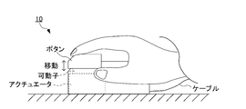
- FIG. 11 is a schematic view showing a configuration example of a mounting unit 10 having a mouse shape as a pointing device.
- the mouse-shaped mounting unit 10 is provided with a button (a portion on which a user's finger is placed) at the tip, and an actuator for presenting a force-tactile sensation is provided at the lower portion of the button in the mounting unit 10. Is provided. Further, the button is connected to a mover operated by an actuator.
- the mouse-shaped wearing unit 10 also has a function as a pointing device for moving the mouse cursor, like a normal mouse.
- the user holds the mouse-shaped mounting unit 10 by hand and moves the mouse cursor to move the mouse cursor to the space (virtual space, remote space, etc.) in which the contact object presented on the screen exists.
- the actuator for presenting the force-tactile sensation presents the feel by moving (advancing / retreating) the mover in the direction in which the button is projected from the mounting unit 10.
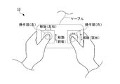
- FIG. 12 is a schematic view showing a configuration example of the mounting unit 10 in the shape of a game controller.
- the mounting unit 10 in the shape of a game controller includes two left and right operation units.
- the left operation unit is a key for movement (for movement operation in the plane direction) and the right.
- the operation unit of the above functions as a button or the like for a click operation.
- These two operation units include an actuator for presenting a force-tactile sensation in the controller body.
- the left operation unit is connected to a mover of an actuator that moves (advances and retreats) in the left-right direction and a mover of an actuator that moves (advances and retreats) in the front-rear direction.
- the operation unit on the right is connected to a mover of an actuator that moves (advances and retreats) in a direction protruding from the controller body. Then, when the mounting unit 10 in the shape of a game controller is held by a fingertip and an action such as touching or stroking a space (virtual space or remote space) in which a contact object exists on the screen is performed, a force-tactile sensation is presented.
- the actuator is used to move (advance and retreat) the mover in the direction of projecting the left and right buttons back and forth and left and right or from the controller body to present a feeling. With such a configuration, the user can feel the impedance of the space (virtual space, remote space, etc.) in which the contact object exists through the mounting unit 10 in the shape of a game controller.
- the position / force control system 1 includes a mounting unit 10 and a control unit 20.
- the mounting unit 10 is mounted on the user's body and presents a force-tactile sensation by the actuator 13.
- the control unit 20 acquires the position data of the mounting unit 10 in the space based on the data of the space in which the contact object exists.
- the mounting unit 10 acquires position data from the control unit 20 and presents force and tactile sensation by controlling the drive of the actuator 13 based on the impedance and contour information of the contact object in space and the position data.
- the control unit 11 is provided.
- the amount of data transmitted from the control unit 20 to the mounting unit 10 can be reduced as compared with the case where the control unit 20 calculates and transmits the information regarding the force and tactile sensation output by the mounting unit 10, so that the control can be performed. It is possible to suppress an increase in signal delay. Therefore, the control of presenting the force and tactile sensation can be realized with a more appropriate system configuration.
- the control unit 11 calculates the reference value of the position and the force based on the impedance and contour information of the contact object in the space and the position data, and the calculated reference value and the information on the position based on the action of the actuator 13. Is input to the coordinate system in which the position and force are independent, the state value in the coordinate system is made to follow the target value of the position and force, and then the inverse transformation of the conversion is performed on the calculation result.
- the drive of the actuator 13 is controlled by calculating the parameters for controlling the actuator 13. This makes it possible to set independent target values for the position and force and control the actuator 13 to realize these target values.
- the mounting unit 10 stores impedance and contour information of a contact object in space in advance.
- the control unit 11 presents a force-tactile sensation by referring to the stored impedance and contour information of the contact object and sequentially acquiring the position data acquired by the control unit 20 to control the drive of the actuator 13. do.
- the mounting unit 10 it is possible to control the drive of the actuator 13 and present the force and tactile sensation by acquiring the position data from the control unit 20.
- the control unit 11 obtains impedance and contour information of the contact object acquired from the control unit 20 at least when the position of the mounting unit 10 in space reaches the boundary of the contact object or immediately before reaching the boundary.
- the force and tactile sensation is presented by sequentially acquiring the position data acquired by the control unit 20 and controlling the drive of the actuator 13.
- the drive of the actuator 13 is controlled by acquiring the position data while appropriately acquiring the necessary physical parameters (impedance and contour information of the contact object) from the control unit 20. It is possible to present a sense of force and touch.
- the control unit 20 acquires data on a reference position of the mounting unit 10 in the space.
- the mounting unit 10 acquires the data of the reference position of the mounting unit 10 from the control unit 20, calculates the relative position representing the portion of the mounting unit 10 in the space based on the data of the reference position, and then calculates the relative position. Controls the drive of the actuator 13. As a result, the data of the reference position of the mounting unit 10 may be transmitted from the control unit 20 to the mounting unit 10, so that the amount of data transmitted from the control unit 20 to the mounting unit 10 can be reduced.
- the control unit 20 acquires position data representing a portion of the mounting unit 10 in space.
- the mounting unit 10 acquires position data representing a portion of the mounting unit 10 from the control unit 20 and controls the drive of the actuator 13.
- the control unit 20 since the data of the position of the portion of the mounting unit 10 (the portion that comes into contact with the contact object, etc.) is acquired, the amount of calculation in the mounting unit 10 can be reduced.
- the present invention is not limited to the above-described embodiment, and modifications, improvements, and the like within the range in which the object of the present invention can be achieved are included in the present invention.
- the control unit 20 detects the position and orientation of the mounting unit 10 based on the images captured by the plurality of image pickup devices C, and calculates the position information in the space.
- the explanation has been given as an example, but the present invention is not limited to this.
- the position information in the space may be calculated by inputting the position and posture of the mounting unit 10 in the space where the contact object exists with an input device such as a mouse.
- the reference value or the target value after coordinate conversion
- the reference value determined based on the function that defines the feel of the object is set as the value corresponding to scaling.
- other methods can be used as long as the feel presented to the user is emphasized or suppressed.
- the texture is enlarged or reduced and presented to the user by giving a gain to the input to the actuator. It is also possible to do.
- the processing in the above-described embodiment can be executed by either hardware or software. That is, it is sufficient that the position / force control system 1 is provided with a function capable of executing the above-mentioned processing, and what kind of functional configuration and hardware configuration are used to realize this function is not limited to the above-mentioned example. ..
- the above processing is executed by software, the programs constituting the software are installed on the computer from a network or a storage medium.
- the storage medium for storing the program is composed of a removable medium distributed separately from the main body of the device, a storage medium preliminarily incorporated in the main body of the device, or the like.
- the removable media is composed of, for example, a semiconductor memory, a magnetic disk, an optical disk, a magneto-optical disk, or the like.
- the optical disk is composed of, for example, a CD-ROM (Compact Disc-Read Only Memory), a DVD (Digital entirely Disk), a Blu-ray Disc (registered trademark), or the like.
- the magneto-optical disk is composed of an MD (Mini-Disc) or the like.
- the storage medium preliminarily incorporated in the apparatus main body is composed of, for example, a ROM (Read Only Memory) or a hard disk in which a program is stored, a hard disk, a semiconductor memory, or the like.
- 1 position / force control system 10 mounting unit, 11,21 control unit, 211 image display control unit, 212 spatial position information acquisition unit, 213 spatial position information transmission unit, 214 physical parameter transmission unit, 12 driver, 13 actuator, 14 Position sensor, 15, 24 storage unit, 16, 25 communication unit, 20 control unit, 22 input unit, 23 output unit, 30 display unit, 40 network, 50 position sensor, 60 storage unit, FT function-based force / speed allocation conversion Block, FC ideal power source block, PC ideal speed (position) source block, IFT inverse conversion block, S control target system
Landscapes
- Engineering & Computer Science (AREA)
- General Engineering & Computer Science (AREA)
- Theoretical Computer Science (AREA)
- Human Computer Interaction (AREA)
- Physics & Mathematics (AREA)
- General Physics & Mathematics (AREA)
- Robotics (AREA)
- Mechanical Engineering (AREA)
- User Interface Of Digital Computer (AREA)
Priority Applications (2)
| Application Number | Priority Date | Filing Date | Title |
|---|---|---|---|
| JP2022503382A JPWO2021172580A1 (https=) | 2020-02-27 | 2021-02-27 | |
| US17/802,933 US12111966B2 (en) | 2020-02-27 | 2021-02-27 | Position/force control system, worn unit, control unit, position/force control method, and storage medium |
Applications Claiming Priority (2)
| Application Number | Priority Date | Filing Date | Title |
|---|---|---|---|
| JP2020-032447 | 2020-02-27 | ||
| JP2020032447 | 2020-02-27 |
Publications (1)
| Publication Number | Publication Date |
|---|---|
| WO2021172580A1 true WO2021172580A1 (ja) | 2021-09-02 |
Family
ID=77491647
Family Applications (1)
| Application Number | Title | Priority Date | Filing Date |
|---|---|---|---|
| PCT/JP2021/007588 Ceased WO2021172580A1 (ja) | 2020-02-27 | 2021-02-27 | 位置・力制御システム、装着ユニット、制御ユニット、位置・力制御方法及びプログラム |
Country Status (3)
| Country | Link |
|---|---|
| US (1) | US12111966B2 (https=) |
| JP (1) | JPWO2021172580A1 (https=) |
| WO (1) | WO2021172580A1 (https=) |
Cited By (2)
| Publication number | Priority date | Publication date | Assignee | Title |
|---|---|---|---|---|
| WO2023234197A1 (ja) * | 2022-06-02 | 2023-12-07 | ソニーグループ株式会社 | 情報処理装置、情報処理方法及び情報処理プログラム |
| US12498789B2 (en) | 2021-06-25 | 2025-12-16 | Keio University | Operational data management system, operational data management method, and storage medium |
Families Citing this family (1)
| Publication number | Priority date | Publication date | Assignee | Title |
|---|---|---|---|---|
| JP2023133635A (ja) * | 2020-07-30 | 2023-09-26 | ソニーグループ株式会社 | 情報処理装置、触感提示システム及びプログラム |
Citations (5)
| Publication number | Priority date | Publication date | Assignee | Title |
|---|---|---|---|---|
| JP2000047567A (ja) * | 1998-07-24 | 2000-02-18 | Dainippon Printing Co Ltd | 物体の接触感シミュレーション装置 |
| JP2004318400A (ja) * | 2003-04-15 | 2004-11-11 | Seiko Epson Corp | 画像処理装置及び画像処理方法 |
| JP2011238069A (ja) * | 2010-05-11 | 2011-11-24 | Nippon Hoso Kyokai <Nhk> | 仮想力覚提示装置及び仮想力覚提示プログラム |
| JP2017168121A (ja) * | 2007-09-14 | 2017-09-21 | 国立研究開発法人産業技術総合研究所 | 情報処理方法 |
| WO2019117309A1 (ja) * | 2017-12-14 | 2019-06-20 | 学校法人慶應義塾 | 位置・力制御装置 |
Family Cites Families (26)
| Publication number | Priority date | Publication date | Assignee | Title |
|---|---|---|---|---|
| JP3230615B2 (ja) | 1992-11-30 | 2001-11-19 | オリンパス光学工業株式会社 | 触診装置 |
| JP3248821B2 (ja) | 1994-11-18 | 2002-01-21 | 敏男 福田 | アクチュエータの作動方法及び装置 |
| US6852107B2 (en) | 2002-01-16 | 2005-02-08 | Computer Motion, Inc. | Minimally invasive surgical training using robotics and tele-collaboration |
| JP2001067113A (ja) | 1999-08-30 | 2001-03-16 | Toshiba Corp | プラント操作評価システム |
| JP4403474B2 (ja) | 1999-12-09 | 2010-01-27 | ソニー株式会社 | 触覚提示機構及びこれを用いた力触覚提示装置 |
| JP3624374B2 (ja) * | 2000-12-12 | 2005-03-02 | 独立行政法人産業技術総合研究所 | 力覚呈示装置 |
| JP3769469B2 (ja) | 2001-03-28 | 2006-04-26 | 株式会社東芝 | 操作訓練用装置 |
| JP2002312003A (ja) | 2001-04-13 | 2002-10-25 | Yaskawa Electric Corp | サーボ制御方法 |
| US7672741B2 (en) | 2003-07-24 | 2010-03-02 | Keio University | Position/force control device |
| JP4613861B2 (ja) | 2006-03-30 | 2011-01-19 | アイシン・エィ・ダブリュ株式会社 | 電動駆動制御装置及び電動駆動制御方法 |
| JP2008217260A (ja) * | 2007-03-01 | 2008-09-18 | Shibaura Institute Of Technology | 力覚提示装置 |
| US11325029B2 (en) | 2007-09-14 | 2022-05-10 | National Institute Of Advanced Industrial Science And Technology | Virtual reality environment generating apparatus and controller apparatus |
| JP5011067B2 (ja) | 2007-10-31 | 2012-08-29 | 株式会社東芝 | マニピュレータシステム |
| JP2009279699A (ja) | 2008-05-21 | 2009-12-03 | Nagaoka Univ Of Technology | 位置・力再現方法および位置・力再現装置 |
| JP5761730B2 (ja) | 2010-01-28 | 2015-08-12 | 長崎県公立大学法人 | 身体技能習得支援装置 |
| WO2013108356A1 (ja) | 2012-01-16 | 2013-07-25 | 三菱電機株式会社 | モータ制御装置 |
| JP6194550B2 (ja) | 2013-04-26 | 2017-09-13 | 学校法人自治医科大学 | 手技シミュレータ |
| WO2015041046A1 (ja) | 2013-09-19 | 2015-03-26 | 学校法人慶應義塾 | 位置・力制御装置、位置・力制御方法及びプログラム |
| US10146308B2 (en) * | 2014-10-14 | 2018-12-04 | Immersion Corporation | Systems and methods for impedance coupling for haptic devices |
| US10509468B2 (en) * | 2016-01-27 | 2019-12-17 | Tactai, Inc. | Providing fingertip tactile feedback from virtual objects |
| US20180350086A1 (en) | 2017-05-31 | 2018-12-06 | Qualcomm Incorporated | System And Method Of Dynamically Filtering Depth Estimates To Generate A Volumetric Map Of A Three-Dimensional Environment Having An Adjustable Maximum Depth |
| JP6964293B2 (ja) | 2018-03-08 | 2021-11-10 | 地方独立行政法人神奈川県立産業技術総合研究所 | 力触覚伝達システム、力触覚伝達方法及びプログラム |
| JP7347774B2 (ja) | 2018-07-06 | 2023-09-20 | 地方独立行政法人神奈川県立産業技術総合研究所 | 医療用把持装置 |
| JP7369383B2 (ja) | 2018-09-03 | 2023-10-26 | 慶應義塾 | 機能生成装置、機能生成方法及びプログラム |
| WO2020162619A1 (ja) | 2019-02-07 | 2020-08-13 | 学校法人慶應義塾 | 位置・力制御装置、位置・力制御方法及びプログラム |
| WO2021025087A1 (ja) | 2019-08-05 | 2021-02-11 | 学校法人慶應義塾 | 位置・力制御装置、位置・力制御方法及びプログラム |
-
2021
- 2021-02-27 WO PCT/JP2021/007588 patent/WO2021172580A1/ja not_active Ceased
- 2021-02-27 US US17/802,933 patent/US12111966B2/en active Active
- 2021-02-27 JP JP2022503382A patent/JPWO2021172580A1/ja active Pending
Patent Citations (5)
| Publication number | Priority date | Publication date | Assignee | Title |
|---|---|---|---|---|
| JP2000047567A (ja) * | 1998-07-24 | 2000-02-18 | Dainippon Printing Co Ltd | 物体の接触感シミュレーション装置 |
| JP2004318400A (ja) * | 2003-04-15 | 2004-11-11 | Seiko Epson Corp | 画像処理装置及び画像処理方法 |
| JP2017168121A (ja) * | 2007-09-14 | 2017-09-21 | 国立研究開発法人産業技術総合研究所 | 情報処理方法 |
| JP2011238069A (ja) * | 2010-05-11 | 2011-11-24 | Nippon Hoso Kyokai <Nhk> | 仮想力覚提示装置及び仮想力覚提示プログラム |
| WO2019117309A1 (ja) * | 2017-12-14 | 2019-06-20 | 学校法人慶應義塾 | 位置・力制御装置 |
Cited By (2)
| Publication number | Priority date | Publication date | Assignee | Title |
|---|---|---|---|---|
| US12498789B2 (en) | 2021-06-25 | 2025-12-16 | Keio University | Operational data management system, operational data management method, and storage medium |
| WO2023234197A1 (ja) * | 2022-06-02 | 2023-12-07 | ソニーグループ株式会社 | 情報処理装置、情報処理方法及び情報処理プログラム |
Also Published As
| Publication number | Publication date |
|---|---|
| US20230134614A1 (en) | 2023-05-04 |
| JPWO2021172580A1 (https=) | 2021-09-02 |
| US12111966B2 (en) | 2024-10-08 |
Similar Documents
| Publication | Publication Date | Title |
|---|---|---|
| JP4930100B2 (ja) | 力触覚ディスプレイ、力触覚ディスプレイの制御方法、並びにコンピュータ・プログラム | |
| US8350843B2 (en) | Virtual hand: a new 3-D haptic interface and system for virtual environments | |
| JP4645678B2 (ja) | 情報入出力装置及び情報入出力方法、並びにコンピュータ・プログラム | |
| JP2018142313A (ja) | 仮想感情タッチのためのシステム及び方法 | |
| US11069079B2 (en) | Interaction with physical objects as proxy objects representing virtual objects | |
| WO2021172580A1 (ja) | 位置・力制御システム、装着ユニット、制御ユニット、位置・力制御方法及びプログラム | |
| JP7772591B2 (ja) | 位置・力制御装置、位置・力制御方法及びプログラム | |
| JP2009276996A (ja) | 情報処理装置、情報処理方法 | |
| CN111665933A (zh) | 虚拟或者增强现实中的对象操作方法及装置 | |
| US20230273685A1 (en) | Method and Arrangement for Handling Haptic Feedback | |
| JP2018113025A (ja) | 触覚によるコンプライアンス錯覚のためのシステム及び方法 | |
| KR20200036261A (ko) | 가상 객체 접촉시 실감 피드백을 제공하는 방법 및 이를 위한 장치 | |
| US20250238083A1 (en) | Device for intuitive dexterous touch and feel interaction in virtual worlds | |
| JP7822205B2 (ja) | 遠隔操作システム | |
| WO2017169827A1 (ja) | 情報処理装置、表示制御方法及びプログラム | |
| KR100670792B1 (ko) | 핸드 인터페이스를 이용한 가상 생산 시스템 및 그 방법 | |
| WO2022076236A1 (en) | Haptic engine for spatial computing | |
| KR102242200B1 (ko) | 햅틱입력장치 및 그 동작 방법 | |
| CN116339517A (zh) | 基于机器人的闭环双向交互数字孪生系统及其构建方法 | |
| CN117251058B (zh) | 一种多信息体感交互系统的控制方法 | |
| CN117572965B (zh) | 一种用于虚拟现实系统的多信息体感交互手套系统 | |
| Waquas | Haptic Technology-A Sense of Real Touch | |
| WO2006070495A1 (ja) | インタフェース装置 | |
| TW202543705A (zh) | 體感回饋方法及系統及非暫態電腦可讀取儲存媒體 | |
| WO2024030641A1 (en) | Robot avatar |
Legal Events
| Date | Code | Title | Description |
|---|---|---|---|
| 121 | Ep: the epo has been informed by wipo that ep was designated in this application |
Ref document number: 21759829 Country of ref document: EP Kind code of ref document: A1 |
|
| ENP | Entry into the national phase |
Ref document number: 2022503382 Country of ref document: JP Kind code of ref document: A |
|
| WWE | Wipo information: entry into national phase |
Ref document number: 202217054646 Country of ref document: IN |
|
| NENP | Non-entry into the national phase |
Ref country code: DE |
|
| 122 | Ep: pct application non-entry in european phase |
Ref document number: 21759829 Country of ref document: EP Kind code of ref document: A1 |