WO2021172580A1 - Position/force control system, worn unit, control unit, position/force control method, and program - Google Patents
Position/force control system, worn unit, control unit, position/force control method, and program Download PDFInfo
- Publication number
- WO2021172580A1 WO2021172580A1 PCT/JP2021/007588 JP2021007588W WO2021172580A1 WO 2021172580 A1 WO2021172580 A1 WO 2021172580A1 JP 2021007588 W JP2021007588 W JP 2021007588W WO 2021172580 A1 WO2021172580 A1 WO 2021172580A1
- Authority
- WO
- WIPO (PCT)
- Prior art keywords
- force
- space
- mounting unit
- data
- unit
- Prior art date
Links
Images


Classifications
-
- G—PHYSICS
- G06—COMPUTING; CALCULATING OR COUNTING
- G06F—ELECTRIC DIGITAL DATA PROCESSING
- G06F3/00—Input arrangements for transferring data to be processed into a form capable of being handled by the computer; Output arrangements for transferring data from processing unit to output unit, e.g. interface arrangements
- G06F3/01—Input arrangements or combined input and output arrangements for interaction between user and computer
- G06F3/016—Input arrangements with force or tactile feedback as computer generated output to the user
-
- B—PERFORMING OPERATIONS; TRANSPORTING
- B25—HAND TOOLS; PORTABLE POWER-DRIVEN TOOLS; MANIPULATORS
- B25J—MANIPULATORS; CHAMBERS PROVIDED WITH MANIPULATION DEVICES
- B25J13/00—Controls for manipulators
-
- B—PERFORMING OPERATIONS; TRANSPORTING
- B25—HAND TOOLS; PORTABLE POWER-DRIVEN TOOLS; MANIPULATORS
- B25J—MANIPULATORS; CHAMBERS PROVIDED WITH MANIPULATION DEVICES
- B25J13/00—Controls for manipulators
- B25J13/02—Hand grip control means
-
- G—PHYSICS
- G06—COMPUTING; CALCULATING OR COUNTING
- G06F—ELECTRIC DIGITAL DATA PROCESSING
- G06F3/00—Input arrangements for transferring data to be processed into a form capable of being handled by the computer; Output arrangements for transferring data from processing unit to output unit, e.g. interface arrangements
- G06F3/01—Input arrangements or combined input and output arrangements for interaction between user and computer
- G06F3/011—Arrangements for interaction with the human body, e.g. for user immersion in virtual reality
Definitions
- the present invention relates to a position / force control system, a mounting unit, a control unit, a position / force control method, and a program that present a position and force to a user.
- the device (exoskeleton type wearing unit, etc.) mounted on the user's body is controlled from a PC (Personal Computer), a server, or the like. .. Therefore, the delay of the control signal for the device worn on the user's body becomes large, and there is a possibility that appropriate control cannot be performed.
- An object of the present invention is to realize a control that presents a force-tactile sensation with a more appropriate system configuration.
- the position / force control system includes a mounting unit that is mounted on the user's body and presents a force-tactile sensation by an actuator, and a control unit that acquires data on the position of the mounting unit in the space based on data in the space where the contact object exists.
- the mounting unit acquires the position data from the control unit and controls the drive of the actuator based on the impedance and contour information of the contact object in the space and the position data. It is characterized by being provided with a control means for presenting a force-tactile sensation.
- control for presenting force and tactile sensation can be realized with a more appropriate system configuration.
- the force-tactile sensation when it comes into contact with an object is treated as information including a texture representing the feel of the surface of the object, and is presented to the user by the device.
- the rigidity, viscosity, and inertia (impedance of the object) of the object to be contacted the force-tactile sensation when the object is in contact is treated as information.
- the position / force control system according to the present invention includes a control unit composed of an information processing device such as a PC and a wearing unit worn on the user's body.
- the control unit acquires information (position of the mounting unit in the virtual space or remote space, etc.) regarding the position in the space (virtual space, remote space, etc.) in which the contact object exists.
- the mounting unit is composed of a device (exoskeleton type robot, etc.) mounted on the user's body, and drives an actuator for artificially creating a reaction from an object to give the user a sense of force and touch. introduce.
- the control unit acquires (calculates) information regarding the position of the mounting unit in the space where the contact object exists (hereinafter, referred to as “position information in space”), and outputs the information to the mounting unit.
- the acquired spatial position information is sequentially transmitted to the mounting unit without calculating the information representing the force-tactile sensation (position and force output by the actuator, etc.).
- the mounting unit stores physical parameters (here, impedance and contour information of the object) corresponding to the position of the space in which the contact object exists.
- the mounting unit provides the spatial position information transmitted from the control unit and the information regarding the position of the output shaft (or the member that operates corresponding to the output shaft) of the actuator (hereinafter, referred to as "output position information"). Based on this, using the physical parameters of the object that is the contact object, information representing the force-tactile sensation from the contact object including the texture is calculated, and the actuator is controlled to present the force-tactile sensation to the user.
- the amount of data transmitted from the control unit to the mounting unit can be reduced as compared with the case where the control unit calculates and transmits the information on the force and tactile sensation output by the mounting unit. Therefore, it is possible to suppress an increase in the delay of the control signal. Therefore, the control of presenting the force and tactile sensation can be realized with a more appropriate system configuration.
- the impedance of the object to be contacted is used in order to handle the force and tactile sensation when the object is in contact with the object as information. Since the impedance of an object is represented by the rigidity, viscosity and inertia of the contact object, these values can be acquired and used for control when the rigidity, viscosity and inertia of the contact object are known. ..
- the values of the rigidity, viscosity, and inertia (impedance of the object) estimated by actually contacting the contact object can be used for control.
- the parameters in the real space are coordinate-converted into a coordinate system that can handle the position and the force independently in order to perform the calculation related to the force and tactile sensation when the object comes into contact with the object.
- This coordinate transformation is defined as a transformation representing the control function of force and tactile sensation, and for example, the one shown as the coordinate transformation representing the transmission function of force and tactile sensation in International Publication No. 2015/041046 is used. Can be done.
- the concept of the force-tactile control function includes controlling the force-tactile sensation felt by humans and controlling the position, speed, force, etc. output by the machine.
- the input vector representing the position and the force in the real space is coordinate-converted into the vector of the above coordinate system, and the state value (vector element) obtained by the coordinate conversion in this coordinate system is performed.
- the state value vector element obtained by the coordinate conversion in this coordinate system is performed.
- the force-tactile control function is realized and the parameters acquired in this series of control are realized.
- the impedance (rigidity, viscosity and inertia) of the object to be contacted is estimated based on.
- an actuator on the side that contacts the object to be contacted and an actuator on the side that transmits force and tactile sensation to the user are provided as in the master / slave system.
- a device or the like including one actuator having a predetermined reference value (a reference value representing a predetermined contact force, etc.) as an input can be used.
- the rigidity, viscosity and inertia (impedance) of the object to be contacted are made unique, and the reaction force from the object is the position and plane of the surface of the object in the plane direction.
- the texture representing the feel of the surface of the object is computerized.
- rigidity, viscosity, and inertia are constants, and the position that determines the action / reaction with the object is represented by a function whose elements are the position of the surface of the object in the plane direction and the position in the direction perpendicular to the plane. Based on the equation of motion, the feel of the object to be contacted is defined.
- the rigidity, viscosity, and inertia (impedance) of the object to be contacted are made unique, and the feel of the object is set to the position in the plane direction and the position in the direction perpendicular to the plane.
- the texture that expresses the feel of the surface of the object is computerized. Since the feel of an object (force tactile sensation including the texture that expresses the feel of the surface of the object) is influenced not only by the shape of the surface of the object but also by the physical characteristics of the object itself, when defining the feel of the object, the impedance of the object is defined. It is effective to reflect it.
- FIG. 1 is a schematic view showing the concept of the feel of an object in the present invention.
- the impedance rigidity, viscosity and inertia
- the surface shape contour
- the parameter Z representing the impedance of the object does not change
- the reaction force from the object changes depending on the contact position (position x in the plane direction of the object surface and position y in the direction perpendicular to the plane).
- the feel of an object is defined by the rigidity, viscosity and inertia peculiar to the object and the contour information of the surface of the object.
- the feel of the object is defined by the following equations (1) and (2).
- f is the reaction force from the object to be contacted
- m is inertia
- d is viscosity
- k is rigidity
- g is a function representing the contour of the object surface
- t is the time. Represents. Since the function representing the contour of the surface of the object is a function of time t, the equation (2) represents the contour of the surface of the object whose shape changes in response to contact or the like.
- the parameters to be managed in the acquisition or presentation of the feel are the rigidity, viscosity and inertia (impedance) peculiar to the object, the position of the object surface in the plane direction and the position in the direction perpendicular to the plane, and the feel with fewer parameters.
- the rigidity, viscosity and inertia change that is, the impedance differs depending on the contact position
- the rigidity, viscosity and inertia of the object to be contacted are in contact with each other. It can be regarded as a function corresponding to the position of the surface of the object in the plane direction.
- FIG. 2 is a schematic view showing the concept of the feel of an object when it is considered that the rigidity, viscosity, and inertia change at each contact position of the object to be contacted.
- the feel of an object is expressed as the following equation (3) NS.
- the number of parameters to be managed is relative compared to the case where the feel of the object is defined as in equations (1) and (2).
- the texture including the feel of the surface of the object is handled by defining the feel of the object as in the equations (1) and (2).
- FIG. 3 is a schematic view showing the overall configuration of the position / force control system 1 according to the embodiment of the present invention.
- the position / force control system 1 according to the present embodiment is attached to a user (here, the user's hand) and presents a force / tactile sensation to the user, and the attachment unit 10 with respect to the attachment unit 10.
- It includes a control unit 20 for controlling, a display unit 30 for presenting visual information to the user, and a plurality of imaging devices C for detecting the position and orientation of the mounting unit 10.
- the mounting unit 10, the control unit 20, the display unit 30, and the plurality of imaging devices C are configured to be communicable via the network 40.
- the network 40 includes a wired or wireless communication path, and is a communication form such as a public network such as the Internet, a dedicated line, or a direct connection by a communication cable, and includes a mounting unit 10, a control unit 20, a display unit 30, and a plurality of imaging devices C. Achieve communication between.
- the mounting unit 10 is configured as, for example, an exoskeleton-type device having a plurality of joints corresponding to human fingers, and is an actuator that rotates each joint based on spatial position information transmitted from the control unit 20. Control the drive.
- the position information in the space the position (reference position) corresponding to the reference specific portion (for example, the central portion of the wrist) set in the mounting unit 10 is used in the space where the contact object exists. Is possible. In this case, in the mounting unit 10, the relative position from the reference position to each finger is calculated. However, it is also possible to use the position (individual position) corresponding to each finger in the space where the contact object exists as the position information in the space.
- the mounting unit 10 stores parameters representing the physical characteristics of the contact object in the space (virtual space, remote space, etc.) in which the contact object exists.
- the parameters representing the physical properties of the contact object can be, for example, the rigidity, viscosity and inertia (impedance of the object) of the contact object.
- each actuator is based on the spatial position information in the space (virtual space or remote space, etc.) in which the contact object exists, the physical parameters (object impedance and contour information), and the output position information of the actuator.
- the control unit 20 transmits the physical parameters corresponding to the position of the space where the contact object exists in advance to the mounting unit 10 and the control for presenting the force and tactile sensation is executed, the contact object is used. Only the in-space position information in the existing space is sequentially transmitted to the mounting unit 10. Then, in the mounting unit 10, a parameter (actuator) for presenting a force-tactile sensation including the feel of the object based on the spatial position information, the physical parameters (impedance and contour information of the object), and the output position information of the actuator. (Parameter for controlling the drive of) is calculated.
- control unit 20 calculates the parameters for presenting the force-tactile sensation including the feel of the object (parameters for controlling the drive of the actuator) and transmits the parameters from the control unit 20 to the mounting unit 10. It is possible to suppress the delay of the control signal. That is, the control of presenting the force and tactile sensation can be realized with a more appropriate system configuration.
- images of the mounting unit 10 captured from a plurality of directions by the plurality of imaging devices C are sequentially transmitted to the control unit 20.
- the position and orientation of the mounting unit 10 are detected based on the images of the mounting unit 10 captured by the plurality of imaging devices C.
- the contact object is a thin member such as a sheet-shaped member
- the position and orientation of the mounting unit 10 can be acquired not only by a plurality of imaging devices C but also by various devices such as a three-dimensional laser scanner.
- the control unit 20 is composed of, for example, an information processing device such as a PC or a server computer.
- the control unit 20 generates data of a space (virtual space, remote space, etc.) in which a contact object exists by performing three-dimensional modeling.
- the control unit 20 generates an image of a virtual reality space that is three-dimensionally modeled based on the captured image data, or produces an image of the virtual reality space that is three-dimensionally modeled based on the data of three-dimensional computer graphics.
- the control unit 20 detects the position and orientation of the mounting unit 10 based on the images of the mounting unit 10 captured by the plurality of imaging devices C.
- control unit 20 acquires (calculates) the in-space position information of the mounting unit 10 in the space (virtual space, remote space, etc.) in which the contact object exists, based on the detected position and orientation of the mounting unit 10. ), And the acquired spatial position information is sequentially transmitted to the mounting unit 10 without calculating the information representing the force-tactile sensation output by the mounting unit 10 (position and force output by the actuator, etc.).
- control unit 20 transmits the physical parameters of the contact object in the space where the contact object exists to the mounting unit 10.
- the position of the mounting unit 10 indicated by the position information in the space is the position of the contact object having different physical parameters (the boundary of the contact object).
- the physical parameters of the new contact object are transmitted.
- the physical parameters of each contact object in the space where the contact object exists may be collectively transmitted from the control unit 20 to the mounting unit 10 in advance.
- the control unit 20 generates image data for displaying the space in which the contact object exists, and also generates an image of the virtual mounting unit 10 in the space in which the contact object exists. Then, the control unit 20 sequentially transmits the image data for displaying the space in which the generated contact object exists and the image data of the virtual mounting unit 10 to the display unit 30.
- the display unit 30 is composed of, for example, an information processing device such as a PC having a display, and according to image data transmitted from the control unit 20, an image of a space in which a contact object exists and a virtual mounting unit 10 in this space. Display the image of.
- the display unit 30 can also be configured by a head-mounted display, a stationary display, or various image display devices such as a projector.
- FIG. 4 is a schematic diagram showing the network topology of the position / force control system 1.
- the control unit 20 that generates data of the space where the contact object exists and the virtual force tactile sense in the space where the contact object exists are presented.
- the mounting unit 10 to be mounted is located on the opposite side of the network 40.
- FIG. 4 is a schematic diagram showing the network topology of the position / force control system 1.
- the position / force control system 1 it serves as an opportunity for control to present a force / tactile sensation from the control unit 20 to the mounting unit 10 via the network 40 and the communication interface (communication I / F).
- Data position information in space
- the mounting unit 10 parameters for presenting the feel of the object (parameters for controlling the drive of the actuator) are calculated based on the position information in space received from the control unit 20, and the actuator is driven. ..
- the network 40 and communication I / F in FIG. 4 form, for example, a network layer / data link layer / physical layer in the OSI reference model, and an Internet layer / network interface layer in the TCP / IP protocol. do.
- the control that presents the force-tactile sensation is performed at the application layer in either the OSI reference model or the TCP / IP protocol.
- the application layer of the control unit 20 after acquiring the position information in the space, only the process of sequentially transmitting the position information in the space is executed without executing the process for controlling the mounting unit 10.
- the application layer of the mounting unit 10 is based on the spatial position information received from the control unit 20, the physical parameters (impedance and contour information of the object) stored in the mounting unit 10, and the output position information of the actuator. Then, the parameters (control parameters) for controlling the drive of the actuator are sequentially calculated. Then, by sequentially outputting the calculated control parameters from the application layer of the mounting unit 10 to the actuator, the presentation of the force-tactile sensation including the feel of the object is realized. Therefore, in the control loop of the actuator in the mounting unit 10, data transmission / reception does not occur via the network 40 and the communication interface (communication I / F), so that the delay of the control signal can be suppressed.
- FIG. 5 is a block diagram showing a specific configuration example of the mounting unit 10 and the control unit 20 in the position / force control system 1.
- the mounting unit 10 of the position / force control system 1 includes a control unit 11, a driver 12, an actuator 13, a position sensor 14, a storage unit 15, and a communication unit 16.
- the control unit 20 includes a control unit 21, an input unit 22, an output unit 23, a storage unit 24, and a communication unit 25.
- the position / force control system 1 includes a display unit 30 and a plurality of image pickup devices C as described above.
- the control unit 11 includes a processor and a semiconductor memory (ROM (Read Only Memory), RAM (Random Access Memory), etc.), and executes various processes according to a program stored in the storage unit 15. For example, the control unit 11 transforms the parameters in the real space (output position information of the actuator 13 and the like) into a coordinate system that can handle the position and the force independently, and in this coordinate system, the coordinate conversion is performed. An operation is performed to make the obtained state value (vector element) follow the target value for realizing the force-tactile control function.
- ROM Read Only Memory
- RAM Random Access Memory
- control unit 11 reversely transforms the calculation result in the coordinate system into a parameter in the real space, and controls the actuator 13 based on this parameter to present a force-tactile sensation including a texture representing the feel of the surface of the object. can do.
- FIG. 6 is a block diagram showing a control algorithm implemented in the control unit 11.
- the algorithms implemented in the control unit 11 include a function-specific force / speed allocation conversion block FT, at least one of the ideal power source block FC or the ideal speed (position) source block PC, and an inverse conversion block. It is expressed as a control rule including IFT.
- the controlled target system S is composed of the driver 12 and the actuator 13.
- the function-specific force / speed allocation conversion block FT is a block that defines the conversion of control energy into the speed (position) and force regions set according to the function of the controlled system S. Specifically, in the function-specific force / speed allocation conversion block FT, coordinate conversion in which the reference value (reference value) of the function of the controlled system S and the current position (output position information) of the actuator 13 are input. Is defined. In general, this coordinate transformation converts an input vector having a reference value and a current velocity (position) as elements into an output vector consisting of a velocity (position) for calculating a control target value of the velocity (position), and also converts the reference value. And the input vector whose element is the current force is converted into the output vector consisting of the force for calculating the control target value of the force.
- the difference in position is zero and the sum of forces is zero (a force equal to the opposite direction is output) between the input of the position and force calculated from the output position information of the actuator 13 and the reference value.
- the state value in the space after coordinate conversion can be calculated.
- the ideal force source block FC is a block that performs calculations in the force region according to the coordinate transformation defined by the functional force / velocity allocation conversion block FT.
- a target value related to the force when performing a calculation based on the coordinate transformation defined by the functional force / velocity allocation conversion block FT is set.
- This target value is set as a fixed value or a variable value depending on the function to be realized. For example, when realizing a function similar to the function indicated by the reference value, set zero as the target value, and when scaling, set a value obtained by enlarging / reducing the information indicating the function indicated by the reference value. You can do it.
- the ideal velocity (position) source block PC is a block that performs calculations in the velocity (position) region according to the coordinate transformation defined by the functional force / velocity allocation conversion block FT.
- a target value regarding the speed (position) when performing a calculation based on the coordinate conversion defined by the function-specific force / speed allocation conversion block FT is set.
- This target value is set as a fixed value or a variable value depending on the function to be realized. For example, when realizing a function similar to the function indicated by the reference value, zero is set as the target value, and when scaling is performed, a value obtained by enlarging / reducing the information indicating the function to be reproduced is set. can.
- the inverse transformation block IFT is a block that converts values in the region of velocity (position) and force into values in the region of input to the controlled system S (for example, voltage value or current value).
- the detection value of the time-series position detected by the position sensor 14 is input to the control unit 11.
- the detected value of the position in the time series represents the operation of the actuator 13, and the control unit 11 functions with respect to the speed (position) and force information derived from the input detected value (position). Apply the coordinate transformation set according to.
- the driver 12 supplies a current for driving the actuator 13 based on the value in the region of the input to the actuator 13 that has been inversely transformed by the control unit 11.
- the actuator 13 is driven by the current supplied from the driver 12 to control the position of the object to be controlled.
- the position sensor 14 detects the position of the output shaft (or the controlled object) of the actuator 13 and outputs the detected value (output position information) to the control unit 11.
- the storage unit 15 is composed of a storage device such as a semiconductor memory.
- the storage unit 15 stores the physical parameters (impedance and contour information of the object) of the object to be contacted. Further, the storage unit 15 stores functions (equations (1) and (2)) that define the feel of the object to be contacted. Instead of the functions (equations (1) and (2)) that define the feel of the object to be contacted, the table format data calculated based on this function may be stored.
- the communication unit 16 communicates with other devices via a communication cable such as a USB (Universal Serial Bus) cable or a communication network such as the Internet.
- a communication cable such as a USB (Universal Serial Bus) cable
- a communication network such as the Internet.
- control unit 21 includes a processor and semiconductor memory (ROM, RAM, etc.), and executes various processes according to a program stored in the storage unit 24.
- ROM read-only memory
- RAM random access memory
- the control unit 21 is formed with an image display control unit 211, a spatial position information acquisition unit 212, a spatial position information transmission unit 213, and a physical parameter transmission unit 214 as functional configurations.
- the image display control unit 211 generates data in a space (virtual space, remote space, etc.) in which a contact object exists by performing three-dimensional modeling. For example, the image display control unit 211 generates an image of a virtual reality space that is three-dimensionally modeled based on the captured image data, or a virtual reality space that is three-dimensionally modeled based on the data of three-dimensional computer graphics. Generate an image.
- the spatial position information acquisition unit 212 detects the position and orientation of the mounting unit 10 based on the images captured by the plurality of image pickup devices C. Further, the space position information acquisition unit 212 obtains the spatial position information of the mounting unit 10 in the space where the contact object exists (virtual space, remote space, etc.) based on the detected position and posture of the mounting unit 10. Acquire (calculate) sequentially.
- the spatial position information transmission unit 213 sequentially transmits the spatial position information of the mounting unit 10 acquired by the spatial position information acquisition unit 212 to the mounting unit 10.
- the physical parameter transmission unit 214 transmits the physical parameters (impedance and contour information of the object) of the contact object in the space where the contact object exists to the mounting unit 10.
- the position of the mounting unit 10 indicated by the position information in the space is the position of the contact object having different physical parameters (contact object).
- the boundary is reached (or just before it is reached), the physical parameters of the new contact object are transmitted.
- the input unit 22 is composed of a pointing device such as a keyboard or a mouse, and inputs various information according to a user's instruction operation.
- the output unit 23 is composed of a display and a speaker, and displays information and outputs audio under the control of the control unit 21.
- the storage unit 24 is composed of a storage device such as a semiconductor memory or a hard disk, and stores various data and programs used in the three-dimensional object manufacturing device 1. Further, the storage unit 24 stores the physical parameters (impedance and contour information of the object) of the contact object in the space where the contact object exists in association with the position in the space where the contact object exists.
- the communication unit 25 communicates with other devices via a communication cable such as a USB cable or a communication network such as the Internet.
- FIG. 7 is a flowchart illustrating a flow of position information transmission processing executed by the control unit 20.
- the position information transmission process is started in response to an instruction to execute the position information transmission process via the input unit 22 or the communication unit 25.
- the image display control unit 211 generates data in the space (virtual space, remote space, etc.) in which the contact object exists by performing three-dimensional modeling.
- the physical parameter transmission unit 214 transmits the physical parameters (impedance and contour information of the object) of the contact object corresponding to the initial position of the mounting unit 10 to the mounting unit 10 in the space where the contact object exists. ..
- the spatial position information acquisition unit 212 detects the position and orientation of the mounting unit 10 based on the images captured by the plurality of image pickup devices C.
- the space position information acquisition unit 212 positions the mounting unit 10 in space in a space (virtual space, remote space, etc.) in which a contact object exists, based on the detected position and posture of the mounting unit 10. Acquire (calculate) information.
- step S5 the spatial position information transmission unit 213 transmits the spatial position information of the mounting unit 10 acquired by the spatial position information acquisition unit 212 to the mounting unit 10.
- step S6 the physical parameter transmission unit 214 determines whether or not it is necessary to update the physical parameters of the contact object in the space where the contact object exists. Whether or not it is necessary to update the physical parameters of the contact object in the space where the contact object exists depends on whether the position of the mounting unit 10 indicated by the position information in the space is the position of the contact object having different physical parameters ( It can be determined by whether or not the contact object (boundary) has been reached (or immediately before reaching the boundary) or the like.
- step S6 When it is not necessary to update the physical parameters of the contact object in the space where the contact object exists, it is determined as NO in step S6, and the process proceeds to step S8. On the other hand, when it is necessary to update the physical parameters of the contact object in the space where the contact object exists, YES is determined in step S6, and the process proceeds to step S7.
- step S7 the physical parameter transmission unit 214 transmits the physical parameters (impedance and contour information of the object) of the contact object corresponding to the current position of the mounting unit 10 to the mounting unit 10 in the space where the contact object exists. ..
- step S8 the spatial position information acquisition unit 212 determines whether or not the condition for ending the position information transmission process is satisfied. Whether or not the condition for ending the position information transmission process is satisfied is, for example, whether or not the end of the position information transmission process is instructed via the input unit 22 or the communication unit 25, or whether or not the plurality of imaging devices are satisfied. It can be determined by whether or not the mounting unit 10 is no longer detected from the image captured by C.
- step S8 If the condition for ending the position information transmission process is not satisfied, NO is determined in step S8, and the process proceeds to step S3. On the other hand, if the condition for ending the position information transmission process is satisfied, YES is determined in step S8, and the position information transmission process ends.
- FIG. 8 is a flowchart illustrating a flow of force-tactile presentation processing executed by the mounting unit 10.
- the force-tactile presentation process is started when the power of the mounting unit 10 is turned on.
- the control unit 11 receives the physical parameters from the control unit 20 via the communication unit 16. At this time, the control unit 11 stores the received physical parameters in the storage unit 15.
- the control unit 11 receives the spatial position information of the mounting unit 10 via the communication unit 16.
- step S13 the control unit 11 acquires the output position information of the actuator 13 via the position sensor 14.
- step S14 the control unit 11 inputs to the actuator 13 to present a force-tactile sensation including a texture representing the feel of the surface of the object based on the output position information of the actuator 13 and the spatial position information of the mounting unit 10. Calculate the value in the region (here, the current value).
- the control unit 11 sets the physical parameters (impedance and contour information of the object) stored in the storage unit 15 according to the spatial position information of the mounting unit 10. And (see (2)), the reference value corresponding to the contact position of the object to be contacted is calculated. Further, the control unit 11 receives the calculated reference value and the output position information of the actuator 13 as inputs, performs coordinate conversion to a coordinate system capable of handling the position and the force independently, and the state value obtained by the coordinate conversion. Is calculated to follow the target value for realizing the force-tactile control function. Then, the control unit 11 reversely converts the calculation result in the coordinate system into a value in the region of input to the actuator 13.
- step S15 the driver 12 supplies a current for driving the actuator 13 based on the value in the region of the input to the actuator 13 that has been inversely transformed by the control unit 11.
- step S16 the control unit 11 determines whether or not a new physical parameter has been received from the control unit 20 via the communication unit 16. If no new physical parameter is received from the control unit 20 via the communication unit 16, NO is determined in step S16, and the process proceeds to step S18. On the other hand, when a new physical parameter is received from the control unit 20 via the communication unit 16, YES is determined in step S16, and the process proceeds to step S17. In step S17, the control unit 11 updates the physical parameters stored in the storage unit 15 with the newly received physical parameters.
- step S18 the control unit 11 determines whether or not the condition for ending the force-tactile presentation process is satisfied. Whether or not the condition for ending the force-tactile presentation process is satisfied is, for example, whether or not an operation for turning off the power of the mounting unit 10 has been performed, or whether or not the force-tactile presentation is performed via the communication unit 16. It can be determined by whether or not an instruction for terminating the process has been input. If the condition for ending the force-tactile presentation process is not satisfied, NO is determined in step S18, and the process proceeds to step S12. On the other hand, when the condition for ending the force-tactile presentation process is satisfied, YES is determined in step S18, and the force-tactile presentation process ends.
- the control unit 20 acquires (calculates) information (in-space position information) regarding the position of the mounting unit 10 in the space where the contact object exists. ), And the acquired spatial position information is sequentially transmitted to the mounting unit 10 without calculating the information representing the force-tactile sensation output by the mounting unit 10 (position and force output by the actuator 13).
- the mounting unit 10 stores physical parameters (impedance and contour information of the object) corresponding to the position of the space in which the contact object exists.
- the mounting unit 10 comes into contact with each other based on the spatial position information transmitted from the control unit 20 and the information (output position information) regarding the position of the output shaft (or the member operating corresponding to the output shaft) of the actuator 13.
- the actuator 13 is controlled to present the force-tactile sensation to the user.
- the amount of data transmitted from the control unit 20 to the mounting unit 10 is reduced as compared with the case where the control unit 20 calculates and transmits the information on the force and tactile sensation output by the mounting unit 10. Therefore, it is possible to suppress an increase in the delay of the control signal. Therefore, the control of presenting the force and tactile sensation can be realized with a more appropriate system configuration.
- the feel of the object is defined as in the equations (1) and (2), and the texture including the feel of the surface of the object is handled. Therefore, the parameters to be managed in the acquisition or presentation of the feel are the rigidity, viscosity and inertia (impedance) peculiar to the object, the position of the object surface in the plane direction and the position in the direction perpendicular to the plane, and the feel can be achieved with fewer parameters. Can be acquired or presented. Further, according to the position / force control system 1 in the present embodiment, an object in a virtual space or a remote space (a virtual object in a game using the virtual space or a product in the virtual space sold in e-commerce). Or, it is possible to present a force-tactile sensation including a texture representing the feel of the surface of the object when it comes into contact with an object existing in a remote place or the like.
- the mounting unit 10 is configured as an exoskeleton-type device having a plurality of joints corresponding to human fingers.
- the mounting unit 10 can be configured in various forms as follows. In the following example, a configuration in which power is supplied and communication is performed by a cable will be described, but a configuration in which power is supplied by a battery and communication is performed wirelessly (wireless type) is also possible.
- FIG. 9 is a schematic view showing a configuration example of a mounting unit 10 having a ring shape to be fitted to a fingertip.
- a mover operated by an actuator is attached to the inside of the ring-shaped member (ventral side of the finger), and the mover is mounted on the inside of the ring-shaped member.
- the force and tactile sensation is presented through.
- the actuator for presenting the force-tactile sensation is released from the touch surface.
- the feel is presented by moving (advancing and retreating) the actuator in the protruding direction.
- the user can feel the impedance of the space (virtual space, remote space, etc.) in which the contact object exists through the ring-shaped mounting unit 10.
- FIG. 10 is a schematic view showing a configuration example of the pen-shaped mounting unit 10.
- the pen-shaped mounting unit 10 includes a touch pad, a contact portion that comes into contact with a touchable screen, and a rod portion that is held by the user. Further, the contact portion is provided with an actuator for presenting a force-tactile sensation, and the rod portion is connected to a mover operated by the actuator.
- the contact portion is made of a material that can be operated by contacting with a touch pad, a touch panel, or the like.
- the actuator for presenting the force-tactile sensation moves (advances and retreats) the mover in the direction in which the actuator projects from the touch surface (the direction in which the rod portion protrudes from the contact portion). )
- the user can feel the impedance of the space (virtual space, remote space, etc.) in which the contact object exists through the pen-shaped mounting unit 10.
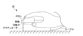
- FIG. 11 is a schematic view showing a configuration example of a mounting unit 10 having a mouse shape as a pointing device.
- the mouse-shaped mounting unit 10 is provided with a button (a portion on which a user's finger is placed) at the tip, and an actuator for presenting a force-tactile sensation is provided at the lower portion of the button in the mounting unit 10. Is provided. Further, the button is connected to a mover operated by an actuator.
- the mouse-shaped wearing unit 10 also has a function as a pointing device for moving the mouse cursor, like a normal mouse.
- the user holds the mouse-shaped mounting unit 10 by hand and moves the mouse cursor to move the mouse cursor to the space (virtual space, remote space, etc.) in which the contact object presented on the screen exists.
- the actuator for presenting the force-tactile sensation presents the feel by moving (advancing / retreating) the mover in the direction in which the button is projected from the mounting unit 10.
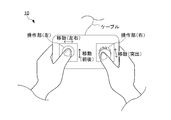
- FIG. 12 is a schematic view showing a configuration example of the mounting unit 10 in the shape of a game controller.
- the mounting unit 10 in the shape of a game controller includes two left and right operation units.
- the left operation unit is a key for movement (for movement operation in the plane direction) and the right.
- the operation unit of the above functions as a button or the like for a click operation.
- These two operation units include an actuator for presenting a force-tactile sensation in the controller body.
- the left operation unit is connected to a mover of an actuator that moves (advances and retreats) in the left-right direction and a mover of an actuator that moves (advances and retreats) in the front-rear direction.
- the operation unit on the right is connected to a mover of an actuator that moves (advances and retreats) in a direction protruding from the controller body. Then, when the mounting unit 10 in the shape of a game controller is held by a fingertip and an action such as touching or stroking a space (virtual space or remote space) in which a contact object exists on the screen is performed, a force-tactile sensation is presented.
- the actuator is used to move (advance and retreat) the mover in the direction of projecting the left and right buttons back and forth and left and right or from the controller body to present a feeling. With such a configuration, the user can feel the impedance of the space (virtual space, remote space, etc.) in which the contact object exists through the mounting unit 10 in the shape of a game controller.
- the position / force control system 1 includes a mounting unit 10 and a control unit 20.
- the mounting unit 10 is mounted on the user's body and presents a force-tactile sensation by the actuator 13.
- the control unit 20 acquires the position data of the mounting unit 10 in the space based on the data of the space in which the contact object exists.
- the mounting unit 10 acquires position data from the control unit 20 and presents force and tactile sensation by controlling the drive of the actuator 13 based on the impedance and contour information of the contact object in space and the position data.
- the control unit 11 is provided.
- the amount of data transmitted from the control unit 20 to the mounting unit 10 can be reduced as compared with the case where the control unit 20 calculates and transmits the information regarding the force and tactile sensation output by the mounting unit 10, so that the control can be performed. It is possible to suppress an increase in signal delay. Therefore, the control of presenting the force and tactile sensation can be realized with a more appropriate system configuration.
- the control unit 11 calculates the reference value of the position and the force based on the impedance and contour information of the contact object in the space and the position data, and the calculated reference value and the information on the position based on the action of the actuator 13. Is input to the coordinate system in which the position and force are independent, the state value in the coordinate system is made to follow the target value of the position and force, and then the inverse transformation of the conversion is performed on the calculation result.
- the drive of the actuator 13 is controlled by calculating the parameters for controlling the actuator 13. This makes it possible to set independent target values for the position and force and control the actuator 13 to realize these target values.
- the mounting unit 10 stores impedance and contour information of a contact object in space in advance.
- the control unit 11 presents a force-tactile sensation by referring to the stored impedance and contour information of the contact object and sequentially acquiring the position data acquired by the control unit 20 to control the drive of the actuator 13. do.
- the mounting unit 10 it is possible to control the drive of the actuator 13 and present the force and tactile sensation by acquiring the position data from the control unit 20.
- the control unit 11 obtains impedance and contour information of the contact object acquired from the control unit 20 at least when the position of the mounting unit 10 in space reaches the boundary of the contact object or immediately before reaching the boundary.
- the force and tactile sensation is presented by sequentially acquiring the position data acquired by the control unit 20 and controlling the drive of the actuator 13.
- the drive of the actuator 13 is controlled by acquiring the position data while appropriately acquiring the necessary physical parameters (impedance and contour information of the contact object) from the control unit 20. It is possible to present a sense of force and touch.
- the control unit 20 acquires data on a reference position of the mounting unit 10 in the space.
- the mounting unit 10 acquires the data of the reference position of the mounting unit 10 from the control unit 20, calculates the relative position representing the portion of the mounting unit 10 in the space based on the data of the reference position, and then calculates the relative position. Controls the drive of the actuator 13. As a result, the data of the reference position of the mounting unit 10 may be transmitted from the control unit 20 to the mounting unit 10, so that the amount of data transmitted from the control unit 20 to the mounting unit 10 can be reduced.
- the control unit 20 acquires position data representing a portion of the mounting unit 10 in space.
- the mounting unit 10 acquires position data representing a portion of the mounting unit 10 from the control unit 20 and controls the drive of the actuator 13.
- the control unit 20 since the data of the position of the portion of the mounting unit 10 (the portion that comes into contact with the contact object, etc.) is acquired, the amount of calculation in the mounting unit 10 can be reduced.
- the present invention is not limited to the above-described embodiment, and modifications, improvements, and the like within the range in which the object of the present invention can be achieved are included in the present invention.
- the control unit 20 detects the position and orientation of the mounting unit 10 based on the images captured by the plurality of image pickup devices C, and calculates the position information in the space.
- the explanation has been given as an example, but the present invention is not limited to this.
- the position information in the space may be calculated by inputting the position and posture of the mounting unit 10 in the space where the contact object exists with an input device such as a mouse.
- the reference value or the target value after coordinate conversion
- the reference value determined based on the function that defines the feel of the object is set as the value corresponding to scaling.
- other methods can be used as long as the feel presented to the user is emphasized or suppressed.
- the texture is enlarged or reduced and presented to the user by giving a gain to the input to the actuator. It is also possible to do.
- the processing in the above-described embodiment can be executed by either hardware or software. That is, it is sufficient that the position / force control system 1 is provided with a function capable of executing the above-mentioned processing, and what kind of functional configuration and hardware configuration are used to realize this function is not limited to the above-mentioned example. ..
- the above processing is executed by software, the programs constituting the software are installed on the computer from a network or a storage medium.
- the storage medium for storing the program is composed of a removable medium distributed separately from the main body of the device, a storage medium preliminarily incorporated in the main body of the device, or the like.
- the removable media is composed of, for example, a semiconductor memory, a magnetic disk, an optical disk, a magneto-optical disk, or the like.
- the optical disk is composed of, for example, a CD-ROM (Compact Disc-Read Only Memory), a DVD (Digital entirely Disk), a Blu-ray Disc (registered trademark), or the like.
- the magneto-optical disk is composed of an MD (Mini-Disc) or the like.
- the storage medium preliminarily incorporated in the apparatus main body is composed of, for example, a ROM (Read Only Memory) or a hard disk in which a program is stored, a hard disk, a semiconductor memory, or the like.
- 1 position / force control system 10 mounting unit, 11,21 control unit, 211 image display control unit, 212 spatial position information acquisition unit, 213 spatial position information transmission unit, 214 physical parameter transmission unit, 12 driver, 13 actuator, 14 Position sensor, 15, 24 storage unit, 16, 25 communication unit, 20 control unit, 22 input unit, 23 output unit, 30 display unit, 40 network, 50 position sensor, 60 storage unit, FT function-based force / speed allocation conversion Block, FC ideal power source block, PC ideal speed (position) source block, IFT inverse conversion block, S control target system
Abstract
[Problem] To realize control for presenting a force-tactile sense in a more appropriate system configuration. [Solution] A position/force control system 1 comprises a worn unit 10 and a control unit 20. The worn unit 10 is worn on a user's body and presents a force-tactile sense by means of an actuator 13. The control unit 20 acquires data regarding a position in the space of the worn unit on the basis of data regarding a space where an object to be touched is present. The worn unit 10 comprises a control part 11 that acquires the position data from the control unit 20 and presents the force-tactile sense by controlling the drive of the actuator 13 on the basis of the position data as well as impedance and outline information regarding the object to be touched in the space.
Description
本発明は、ユーザに対して位置及び力を提示する位置・力制御システム、装着ユニット、制御ユニット、位置・力制御方法及びプログラムに関する。
The present invention relates to a position / force control system, a mounting unit, a control unit, a position / force control method, and a program that present a position and force to a user.
近年、物体に接触した際の力触覚をユーザの身体に対して提示する装置が知られている。
例えば、ユーザの手指に装着され、ユーザの各指に対し、アクチュエータを用いて力触覚を伝達することにより、物体に接触した際の感触を伝達する外骨格型の装置等が市販されている。
このような装置を用いることにより、ネットゲーム等において仮想空間内の物体の感触等をユーザに提示することが可能となる。
力触覚をユーザの身体に対して提示する装置は、例えば、特許文献1に記載されている。 In recent years, there has been known a device that presents the force and tactile sensation when it comes into contact with an object to the user's body.
For example, an exoskeleton type device that is attached to a user's finger and transmits a force-tactile sensation to each user's finger by using an actuator to transmit a feeling when it comes into contact with an object is commercially available.
By using such a device, it is possible to present the feel of an object in the virtual space to the user in a net game or the like.
A device that presents a force-tactile sensation to a user's body is described in, for example,Patent Document 1.
例えば、ユーザの手指に装着され、ユーザの各指に対し、アクチュエータを用いて力触覚を伝達することにより、物体に接触した際の感触を伝達する外骨格型の装置等が市販されている。
このような装置を用いることにより、ネットゲーム等において仮想空間内の物体の感触等をユーザに提示することが可能となる。
力触覚をユーザの身体に対して提示する装置は、例えば、特許文献1に記載されている。 In recent years, there has been known a device that presents the force and tactile sensation when it comes into contact with an object to the user's body.
For example, an exoskeleton type device that is attached to a user's finger and transmits a force-tactile sensation to each user's finger by using an actuator to transmit a feeling when it comes into contact with an object is commercially available.
By using such a device, it is possible to present the feel of an object in the virtual space to the user in a net game or the like.
A device that presents a force-tactile sensation to a user's body is described in, for example,
しかしながら、力触覚をユーザの身体に対して提示する従来の技術では、ユーザの身体に装着される装置(外骨格型の装着ユニット等)の制御をPC(Personal Computer)あるいはサーバ等から行っている。
そのため、ユーザの身体に装着される装置に対する制御信号の遅延が大きくなり、適切な制御が行えない可能性がある。
本発明の課題は、力触覚を提示する制御をより適切なシステム構成で実現することである。 However, in the conventional technique of presenting the force and tactile sensation to the user's body, the device (exoskeleton type wearing unit, etc.) mounted on the user's body is controlled from a PC (Personal Computer), a server, or the like. ..
Therefore, the delay of the control signal for the device worn on the user's body becomes large, and there is a possibility that appropriate control cannot be performed.
An object of the present invention is to realize a control that presents a force-tactile sensation with a more appropriate system configuration.
上記課題を解決するため、本発明の一態様に係る位置・力制御システムは、
ユーザの身体に装着され、アクチュエータによって力触覚を提示する装着ユニットと、接触対象物が存在する空間のデータに基づいて、前記装着ユニットの前記空間における位置のデータを取得する制御ユニットとを含み、
前記装着ユニットは、前記制御ユニットから前記位置のデータを取得し、前記空間における前記接触対象物のインピーダンス及び輪郭情報と、前記位置のデータとに基づいて、前記アクチュエータの駆動を制御することにより、力触覚を提示する制御手段を備えることを特徴とする。 In order to solve the above problems, the position / force control system according to one aspect of the present invention is
It includes a mounting unit that is mounted on the user's body and presents a force-tactile sensation by an actuator, and a control unit that acquires data on the position of the mounting unit in the space based on data in the space where the contact object exists.
The mounting unit acquires the position data from the control unit and controls the drive of the actuator based on the impedance and contour information of the contact object in the space and the position data. It is characterized by being provided with a control means for presenting a force-tactile sensation.
本発明によれば、力触覚を提示する制御をより適切なシステム構成で実現することができる。
According to the present invention, control for presenting force and tactile sensation can be realized with a more appropriate system configuration.
以下、本発明の実施形態について、図面を参照して説明する。
初めに、本発明に適用される基本的原理について説明する。 Hereinafter, embodiments of the present invention will be described with reference to the drawings.
First, the basic principle applied to the present invention will be described.
初めに、本発明に適用される基本的原理について説明する。 Hereinafter, embodiments of the present invention will be described with reference to the drawings.
First, the basic principle applied to the present invention will be described.
[基本的原理]
本発明においては、物体に接触した場合の力触覚を、物体表面の感触を表すテクスチャを含めて情報として取り扱い、デバイスによってユーザに提示する。
このとき、接触対象物の剛性、粘性及び慣性(物体のインピーダンス)を用いることにより、物体に接触した場合の力触覚を情報として取り扱う。
また、本発明に係る位置・力制御システムは、PC等の情報処理装置によって構成される制御ユニットと、ユーザの身体に装着される装着ユニットとを備えている。制御ユニットは、接触対象物が存在する空間(仮想空間または遠隔的な空間等)における位置に関する情報(仮想空間または遠隔的な空間内における装着ユニットの位置等)を取得する。また、装着ユニットは、ユーザの身体に装着されるデバイス(外骨格型のロボット等)によって構成され、物体からの反作用を疑似的に創出するためのアクチュエータを駆動することにより、ユーザに力触覚を伝達する。 [Basic principle]
In the present invention, the force-tactile sensation when it comes into contact with an object is treated as information including a texture representing the feel of the surface of the object, and is presented to the user by the device.
At this time, by using the rigidity, viscosity, and inertia (impedance of the object) of the object to be contacted, the force-tactile sensation when the object is in contact is treated as information.
Further, the position / force control system according to the present invention includes a control unit composed of an information processing device such as a PC and a wearing unit worn on the user's body. The control unit acquires information (position of the mounting unit in the virtual space or remote space, etc.) regarding the position in the space (virtual space, remote space, etc.) in which the contact object exists. In addition, the mounting unit is composed of a device (exoskeleton type robot, etc.) mounted on the user's body, and drives an actuator for artificially creating a reaction from an object to give the user a sense of force and touch. introduce.
このような構成において、制御ユニットは、接触対象物が存在する空間における装着ユニットの位置に関する情報(以下、「空間内位置情報」と称する。)を取得(算出)し、装着ユニットで出力される力触覚を表す情報(アクチュエータが出力する位置及び力等)を算出することなく、取得した空間内位置情報を装着ユニットに逐次送信する。装着ユニットは、接触対象物が存在する空間の位置に対応する物理パラメータ(ここでは、物体のインピーダンス及び輪郭情報)を記憶している。そして、装着ユニットは、制御ユニットから送信された空間内位置情報及びアクチュエータの出力軸(または出力軸と対応して動作する部材)の位置に関する情報(以下、「出力位置情報」と称する。)を基に、接触対象物である物体の物理パラメータを用いて、テクスチャを含む接触対象物からの力触覚を表す情報を算出し、アクチュエータを制御してユーザに力触覚を提示する。
In such a configuration, the control unit acquires (calculates) information regarding the position of the mounting unit in the space where the contact object exists (hereinafter, referred to as “position information in space”), and outputs the information to the mounting unit. The acquired spatial position information is sequentially transmitted to the mounting unit without calculating the information representing the force-tactile sensation (position and force output by the actuator, etc.). The mounting unit stores physical parameters (here, impedance and contour information of the object) corresponding to the position of the space in which the contact object exists. Then, the mounting unit provides the spatial position information transmitted from the control unit and the information regarding the position of the output shaft (or the member that operates corresponding to the output shaft) of the actuator (hereinafter, referred to as "output position information"). Based on this, using the physical parameters of the object that is the contact object, information representing the force-tactile sensation from the contact object including the texture is calculated, and the actuator is controlled to present the force-tactile sensation to the user.
上述のような構成とすることにより、制御ユニットが装着ユニットで出力される力触覚に関する情報を算出して送信する場合に比べ、制御ユニットから装着ユニットに送信されるデータ量を低減することができるため、制御信号の遅延が大きくなることを抑制できる。
したがって、力触覚を提示する制御をより適切なシステム構成で実現することができる。 With the above configuration, the amount of data transmitted from the control unit to the mounting unit can be reduced as compared with the case where the control unit calculates and transmits the information on the force and tactile sensation output by the mounting unit. Therefore, it is possible to suppress an increase in the delay of the control signal.
Therefore, the control of presenting the force and tactile sensation can be realized with a more appropriate system configuration.
次に、本発明において、物体に接触した場合の力触覚を情報として取り扱うための手法について説明する。
[物体のインピーダンスの取得]
本発明においては、物体に接触した場合の力触覚を情報として取り扱うために、接触対象の物体におけるインピーダンスが用いられる。物体のインピーダンスは、接触対象物の剛性、粘性及び慣性によって表されるため、接触対象物の剛性、粘性及び慣性が既知である場合には、これらの値を取得して制御に用いることができる。また、接触対象物の剛性、粘性及び慣性が既知でない場合には、接触対象物に実際に接触して推定した剛性、粘性及び慣性(物体のインピーダンス)の値を制御に用いることができる。
物体のインピーダンスを推定する場合、物体に接触した際の力触覚に関する演算を行うために、実空間のパラメータを、位置と力とを独立して取り扱うことが可能な座標系へ座標変換する。この座標変換は、力触覚の制御機能を表す変換として定義されたものであり、例えば、国際公開第2015/041046号において力触覚の伝達機能を表す座標変換として示されているもの等を用いることができる。なお、力触覚の制御機能の概念には、人間が感じる力触覚を制御すること及び機械で出力される位置、速度あるいは力等を制御することが含まれる。 Next, in the present invention, a method for handling the force and tactile sensation when it comes into contact with an object as information will be described.
[Acquisition of impedance of object]
In the present invention, the impedance of the object to be contacted is used in order to handle the force and tactile sensation when the object is in contact with the object as information. Since the impedance of an object is represented by the rigidity, viscosity and inertia of the contact object, these values can be acquired and used for control when the rigidity, viscosity and inertia of the contact object are known. .. When the rigidity, viscosity, and inertia of the contact object are not known, the values of the rigidity, viscosity, and inertia (impedance of the object) estimated by actually contacting the contact object can be used for control.
When estimating the impedance of an object, the parameters in the real space are coordinate-converted into a coordinate system that can handle the position and the force independently in order to perform the calculation related to the force and tactile sensation when the object comes into contact with the object. This coordinate transformation is defined as a transformation representing the control function of force and tactile sensation, and for example, the one shown as the coordinate transformation representing the transmission function of force and tactile sensation in International Publication No. 2015/041046 is used. Can be done. The concept of the force-tactile control function includes controlling the force-tactile sensation felt by humans and controlling the position, speed, force, etc. output by the machine.
そして、アクチュエータの出力位置情報を基に、実空間における位置と力とを表す入力ベクトルを、上記座標系のベクトルに座標変換し、この座標系において、座標変換によって得られる状態値(ベクトルの要素)を、力触覚の制御機能を実現するための目標値に追従させる演算を行う。
さらに、上記座標系における演算結果を実空間のパラメータに逆変換し、このパラメータに基づいてアクチュエータを制御することで、力触覚の制御機能が実現されると共に、この一連の制御において取得されるパラメータを基に、接触対象の物体のインピーダンス(剛性、粘性及び慣性)が推定される。
なお、このように接触対象の物体のインピーダンスを推定する場合、マスタ・スレーブシステムのように、接触対象の物体に接触する側のアクチュエータと、ユーザに力触覚を伝達する側のアクチュエータとを備える形態や、所定の基準値(所定の接触力を表す基準値等)を入力とした1つのアクチュエータを備える形態の装置等を用いることができる。 Then, based on the output position information of the actuator, the input vector representing the position and the force in the real space is coordinate-converted into the vector of the above coordinate system, and the state value (vector element) obtained by the coordinate conversion in this coordinate system is performed. ) Is calculated to follow the target value for realizing the force-tactile control function.
Further, by inversely converting the calculation result in the above coordinate system into a parameter in the real space and controlling the actuator based on this parameter, the force-tactile control function is realized and the parameters acquired in this series of control are realized. The impedance (rigidity, viscosity and inertia) of the object to be contacted is estimated based on.
When estimating the impedance of the object to be contacted in this way, an actuator on the side that contacts the object to be contacted and an actuator on the side that transmits force and tactile sensation to the user are provided as in the master / slave system. Alternatively, a device or the like including one actuator having a predetermined reference value (a reference value representing a predetermined contact force, etc.) as an input can be used.
[物体表面の感触の提示]
このように推定したインピーダンスを用いることにより、実空間または仮想空間における物体表面の感触(具体的には、物体表面の感触を表すテクスチャを含む力触覚)を提示することができる。
物体表面の感触を提示するために、本発明においては、接触対象となる物体の剛性、粘性及び慣性(インピーダンス)を固有のものとし、物体からの反力を物体表面の平面方向の位置及び平面と垂直な方向の位置に対応する関数として定義することで、物体表面の感触を表すテクスチャを情報化する。
具体的には、剛性、粘性及び慣性が定数であり、物体との作用・反作用を決定する位置が物体表面の平面方向の位置及び平面と垂直な方向の位置を要素とする関数で表される運動方程式に基づいて、接触対象となる物体の感触を定義する。 [Presentation of the feel of the surface of the object]
By using the impedance estimated in this way, it is possible to present the feel of the object surface in the real space or the virtual space (specifically, the force tactile sensation including the texture representing the feel of the object surface).
In order to present the feel of the surface of an object, in the present invention, the rigidity, viscosity and inertia (impedance) of the object to be contacted are made unique, and the reaction force from the object is the position and plane of the surface of the object in the plane direction. By defining it as a function corresponding to the position in the direction perpendicular to, the texture representing the feel of the surface of the object is computerized.
Specifically, rigidity, viscosity, and inertia are constants, and the position that determines the action / reaction with the object is represented by a function whose elements are the position of the surface of the object in the plane direction and the position in the direction perpendicular to the plane. Based on the equation of motion, the feel of the object to be contacted is defined.
そして、物体表面の平面方向の位置及び平面と垂直な方向の位置が、実空間または仮想空間の入力として与えられた場合に、接触対象となる物体の感触を定義した関数で定められる値を基準値として入力し、上述の座標系において目標値に追従させる演算を行って、アクチュエータの出力を制御することで、物体表面の感触を表すテクスチャを含めた力触覚を提示することができる。
なお、位置と速度(または加速度)あるいは角度と角速度(または角加速度)は、微積分演算により置換可能なパラメータであるため、位置あるいは角度に関する処理を行う場合、適宜、速度あるいは角速度等に置換することが可能である。 Then, when the position in the plane direction and the position in the direction perpendicular to the plane of the object surface are given as inputs in the real space or the virtual space, the value determined by the function defining the feel of the object to be contacted is used as a reference. By inputting it as a value, performing an operation to follow the target value in the above-mentioned coordinate system, and controlling the output of the actuator, it is possible to present a force-tactile sensation including a texture representing the feel of the surface of the object.
Note that position and velocity (or acceleration) or angle and angular velocity (or angular velocity) are parameters that can be replaced by a minute integration calculation. Therefore, when processing related to position or angle, replace them with velocity or angular velocity as appropriate. Is possible.
[物体の感触を表す関数]
上述のように、本発明においては、接触対象となる物体の剛性、粘性及び慣性(インピーダンス)を固有のものとし、物体の感触を物体表面の平面方向の位置及び平面と垂直な方向の位置に対応する関数として定義することで、物体表面の感触を表すテクスチャを情報化する。
物体の感触(物体表面の感触を表すテクスチャを含めた力触覚)は、物体表面の形状のみならず、物体自体の物理特性の影響を受けるため、物体の感触を定義する場合、物体のインピーダンスを反映させることが有効である。 [Function that expresses the feel of an object]
As described above, in the present invention, the rigidity, viscosity, and inertia (impedance) of the object to be contacted are made unique, and the feel of the object is set to the position in the plane direction and the position in the direction perpendicular to the plane. By defining it as a corresponding function, the texture that expresses the feel of the surface of the object is computerized.
Since the feel of an object (force tactile sensation including the texture that expresses the feel of the surface of the object) is influenced not only by the shape of the surface of the object but also by the physical characteristics of the object itself, when defining the feel of the object, the impedance of the object is defined. It is effective to reflect it.
図1は、本発明における物体の感触の概念を示す模式図である。
図1に示すように、接触対象となる物体表面の形状が滑らかな平面ではなく微小な凹凸を有する場合、物体自体のインピーダンス(剛性、粘性及び慣性)は変化せず、表面の形状(輪郭)が変化していると捉えられる。
この場合、物体のインピーダンスを表すパラメータZは変化しておらず、接触する位置(物体表面の平面方向の位置x及び平面と垂直な方向の位置y)によって物体からの反力が変化すると考えることが、より適切な事象の捉え方であるといえる。
そこで、本発明においては、物体固有の剛性、粘性及び慣性と、物体表面の輪郭情報とによって物体の感触を定義する。
具体的には、以下の式(1)及び(2)によって、物体の感触を定義する。 FIG. 1 is a schematic view showing the concept of the feel of an object in the present invention.
As shown in FIG. 1, when the shape of the surface of the object to be contacted is not a smooth flat surface but has minute irregularities, the impedance (rigidity, viscosity and inertia) of the object itself does not change, and the surface shape (contour) Is perceived as changing.
In this case, it is considered that the parameter Z representing the impedance of the object does not change, and the reaction force from the object changes depending on the contact position (position x in the plane direction of the object surface and position y in the direction perpendicular to the plane). However, it can be said that it is a more appropriate way of grasping an event.
Therefore, in the present invention, the feel of an object is defined by the rigidity, viscosity and inertia peculiar to the object and the contour information of the surface of the object.
Specifically, the feel of the object is defined by the following equations (1) and (2).

なお、式(1)及び(2)において、fは接触対象となる物体からの反力、mは慣性、dは粘性、kは剛性、gは物体表面の輪郭を表す関数、tは時刻を表している。物体表面の輪郭を表す関数が時刻tの関数となっていることから、式(2)は、接触等に応じて形状が変化する物体表面の輪郭を表すものとなっている。
この場合、感触の取得あるいは提示において管理すべきパラメータが、物体固有の剛性、粘性及び慣性(インピーダンス)と、物体表面の平面方向の位置及び平面と垂直な方向の位置となり、より少ないパラメータで感触の取得あるいは提示を行うことができる。
なお、接触対象の物体の接触位置それぞれにおいて、剛性、粘性及び慣性が変化する(即ち、接触位置によってインピーダンスが異なる)ものと捉えた場合、接触対象となる物体の剛性、粘性及び慣性が、接触した物体表面の平面方向の位置に対応する関数であるものとして捉えられる。 In equations (1) and (2), f is the reaction force from the object to be contacted, m is inertia, d is viscosity, k is rigidity, g is a function representing the contour of the object surface, and t is the time. Represents. Since the function representing the contour of the surface of the object is a function of time t, the equation (2) represents the contour of the surface of the object whose shape changes in response to contact or the like.
In this case, the parameters to be managed in the acquisition or presentation of the feel are the rigidity, viscosity and inertia (impedance) peculiar to the object, the position of the object surface in the plane direction and the position in the direction perpendicular to the plane, and the feel with fewer parameters. Can be acquired or presented.
If it is considered that the rigidity, viscosity and inertia change (that is, the impedance differs depending on the contact position) at each contact position of the object to be contacted, the rigidity, viscosity and inertia of the object to be contacted are in contact with each other. It can be regarded as a function corresponding to the position of the surface of the object in the plane direction.
図2は、接触対象の物体の接触位置それぞれにおいて、剛性、粘性及び慣性が変化すると捉えた場合の物体の感触の概念を示す模式図である。
図2に示す概念においては、接触した物体表面の平面方向の位置xに応じてインピーダンスZ1~Z5が変化すると捉えることから、物体の感触は、以下の式(3)のように表現される。 FIG. 2 is a schematic view showing the concept of the feel of an object when it is considered that the rigidity, viscosity, and inertia change at each contact position of the object to be contacted.
In the concept shown in FIG. 2, since regarded as the impedance Z 1 ~ Z 5 in accordance with the position x of the plane direction of the contacted object surface changes, the feel of an object is expressed as the following equation (3) NS.

この場合、剛性、粘性及び慣性のデータを位置毎に持つ必要があることから、式(1)及び(2)のように物体の感触を定義する場合に比べ、管理すべきパラメータの数が相対的に多くなり、実装コストが増加したり、演算量が増大したりする可能性がある。
したがって、本発明においては、式(1)及び(2)のように物体の感触を定義することにより、物体表面の感触を含むテクスチャを取り扱うものとする。 In this case, since it is necessary to have data on rigidity, viscosity, and inertia for each position, the number of parameters to be managed is relative compared to the case where the feel of the object is defined as in equations (1) and (2). There is a possibility that the number of parameters will increase, the mounting cost will increase, and the amount of calculation will increase.
Therefore, in the present invention, the texture including the feel of the surface of the object is handled by defining the feel of the object as in the equations (1) and (2).
なお、式(3)に従って物体の感触を表現し、接触した物体表面の平面方向の位置xに応じてインピーダンスZ1~Z5が変化するものとして取り扱った場合でも、本発明のシステム構成とすることによる一定の効果を奏するものとなる。即ち、式(3)のように物体の感触を定義した場合、式(1)及び(2)のように物体の感触を定義した場合に比べ、装着ユニットにおける演算量は増加するものの、制御ユニットから装着ユニットに対して、位置に関する情報を送信することで、物体表面の感触を表すテクスチャを含めた力触覚を提示することができるため、制御信号の遅延が大きくなることを抑制できる。
Note that express a feel of the object in accordance with Equation (3), even when the impedance Z 1 ~ Z 5 in accordance with the position x of the plane direction of the contacted object surface handled as changes to the system configuration of the present invention It will have a certain effect. That is, when the feel of the object is defined as in the equation (3), the amount of calculation in the mounting unit is increased as compared with the case where the feel of the object is defined as in the equations (1) and (2), but the control unit. By transmitting information about the position to the mounting unit, it is possible to present a force-tactile sensation including a texture representing the feel of the surface of the object, so that it is possible to suppress an increase in the delay of the control signal.
[構成]
次に、本発明のシステム構成について説明する。
図3は、本発明の一実施形態に係る位置・力制御システム1の全体構成を示す模式図である。
図3に示すように、本実施形態に係る位置・力制御システム1は、ユーザ(ここではユーザの手とする)に装着され、ユーザに力触覚を提示する装着ユニット10と、装着ユニット10に対する制御を行う制御ユニット20と、ユーザに視覚的な情報を提示する表示ユニット30と、装着ユニット10の位置及び姿勢を検出する複数の撮像装置Cと、を含んで構成される。 [composition]
Next, the system configuration of the present invention will be described.
FIG. 3 is a schematic view showing the overall configuration of the position /force control system 1 according to the embodiment of the present invention.
As shown in FIG. 3, the position /force control system 1 according to the present embodiment is attached to a user (here, the user's hand) and presents a force / tactile sensation to the user, and the attachment unit 10 with respect to the attachment unit 10. It includes a control unit 20 for controlling, a display unit 30 for presenting visual information to the user, and a plurality of imaging devices C for detecting the position and orientation of the mounting unit 10.
次に、本発明のシステム構成について説明する。
図3は、本発明の一実施形態に係る位置・力制御システム1の全体構成を示す模式図である。
図3に示すように、本実施形態に係る位置・力制御システム1は、ユーザ(ここではユーザの手とする)に装着され、ユーザに力触覚を提示する装着ユニット10と、装着ユニット10に対する制御を行う制御ユニット20と、ユーザに視覚的な情報を提示する表示ユニット30と、装着ユニット10の位置及び姿勢を検出する複数の撮像装置Cと、を含んで構成される。 [composition]
Next, the system configuration of the present invention will be described.
FIG. 3 is a schematic view showing the overall configuration of the position /
As shown in FIG. 3, the position /
これら装着ユニット10、制御ユニット20、表示ユニット30及び複数の撮像装置Cは、ネットワーク40を介して通信可能に構成されている。ネットワーク40は、有線または無線による通信経路を含み、インターネット等の公衆網、専用線あるいは通信ケーブルによる直接接続等の通信形態で、装着ユニット10、制御ユニット20、表示ユニット30及び複数の撮像装置Cの間における通信を実現する。
The mounting unit 10, the control unit 20, the display unit 30, and the plurality of imaging devices C are configured to be communicable via the network 40. The network 40 includes a wired or wireless communication path, and is a communication form such as a public network such as the Internet, a dedicated line, or a direct connection by a communication cable, and includes a mounting unit 10, a control unit 20, a display unit 30, and a plurality of imaging devices C. Achieve communication between.
装着ユニット10は、例えば、人間の手指に対応する複数の関節を備えた外骨格型の装置として構成され、制御ユニット20から送信される空間内位置情報に基づいて、各関節を回転させるアクチュエータの駆動を制御する。なお、空間内位置情報としては、接触対象物が存在する空間において、装着ユニット10に設定された基準となる特定部分(例えば、手首の中央部分等)に対応する位置(基準位置)を用いることが可能である。この場合、装着ユニット10において、基準位置から各手指までの相対位置が算出される。ただし、空間内位置情報として、接触対象物が存在する空間における各手指に対応する位置(個別位置)を用いることも可能である。
The mounting unit 10 is configured as, for example, an exoskeleton-type device having a plurality of joints corresponding to human fingers, and is an actuator that rotates each joint based on spatial position information transmitted from the control unit 20. Control the drive. As the position information in the space, the position (reference position) corresponding to the reference specific portion (for example, the central portion of the wrist) set in the mounting unit 10 is used in the space where the contact object exists. Is possible. In this case, in the mounting unit 10, the relative position from the reference position to each finger is calculated. However, it is also possible to use the position (individual position) corresponding to each finger in the space where the contact object exists as the position information in the space.
また、装着ユニット10には、接触対象物が存在する空間(仮想空間または遠隔的な空間等)における接触対象物の物理特性を表すパラメータが記憶されている。接触対象物の物理特性を表すパラメータは、例えば、接触対象物の剛性、粘性及び慣性(物体のインピーダンス)とすることができる。
Further, the mounting unit 10 stores parameters representing the physical characteristics of the contact object in the space (virtual space, remote space, etc.) in which the contact object exists. The parameters representing the physical properties of the contact object can be, for example, the rigidity, viscosity and inertia (impedance of the object) of the contact object.
物体の感触(物体表面の感触を表すテクスチャを含めた力触覚)は、物体表面の形状のみならず、物体自体の物理特性の影響を受けるため、物体の感触を定義する場合、物体のインピーダンスを反映させることが有効である。
そして、接触対象物が存在する空間(仮想空間または遠隔的な空間等)における空間内位置情報と、物理パラメータ(物体のインピーダンス及び輪郭情報)と、アクチュエータの出力位置情報とに基づいて、各アクチュエータの駆動(各関節の位置及び力)を制御することで、物体の感触を含む力触覚を提示することができる。 Since the feel of an object (force tactile sensation including the texture that expresses the feel of the surface of the object) is influenced not only by the shape of the surface of the object but also by the physical characteristics of the object itself, when defining the feel of the object, the impedance of the object is defined. It is effective to reflect it.
Then, each actuator is based on the spatial position information in the space (virtual space or remote space, etc.) in which the contact object exists, the physical parameters (object impedance and contour information), and the output position information of the actuator. By controlling the drive (position and force of each joint), it is possible to present a force-tactile sensation including the feel of an object.
本実施形態においては、接触対象物が存在する空間の位置に対応する物理パラメータを制御ユニット20から予め装着ユニット10に送信し、力触覚を提示する制御を実行する際には、接触対象物が存在する空間における空間内位置情報のみが装着ユニット10に逐次送信される。そして、装着ユニット10において、空間内位置情報と、物理パラメータ(物体のインピーダンス及び輪郭情報)と、アクチュエータの出力位置情報とに基づいて、物体の感触を含む力触覚を提示するためのパラメータ(アクチュエータの駆動を制御するためのパラメータ)が算出される。
In the present embodiment, when the control unit 20 transmits the physical parameters corresponding to the position of the space where the contact object exists in advance to the mounting unit 10 and the control for presenting the force and tactile sensation is executed, the contact object is used. Only the in-space position information in the existing space is sequentially transmitted to the mounting unit 10. Then, in the mounting unit 10, a parameter (actuator) for presenting a force-tactile sensation including the feel of the object based on the spatial position information, the physical parameters (impedance and contour information of the object), and the output position information of the actuator. (Parameter for controlling the drive of) is calculated.
これにより、制御ユニット20において物体の感触を含む力触覚を提示するためのパラメータ(アクチュエータの駆動を制御するためのパラメータ)を算出して、制御ユニット20から装着ユニット10に送信する場合に比べ、制御信号の遅延が生じることを抑制できる。
即ち、力触覚を提示する制御をより適切なシステム構成で実現することができる。 As a result, as compared with the case where thecontrol unit 20 calculates the parameters for presenting the force-tactile sensation including the feel of the object (parameters for controlling the drive of the actuator) and transmits the parameters from the control unit 20 to the mounting unit 10. It is possible to suppress the delay of the control signal.
That is, the control of presenting the force and tactile sensation can be realized with a more appropriate system configuration.
即ち、力触覚を提示する制御をより適切なシステム構成で実現することができる。 As a result, as compared with the case where the
That is, the control of presenting the force and tactile sensation can be realized with a more appropriate system configuration.
また、本実施形態においては、複数の撮像装置Cで装着ユニット10を複数方向から撮像した画像が制御ユニット20に逐次送信される。そして、制御ユニット20において、複数の撮像装置Cで撮像された装着ユニット10の画像を基に、装着ユニット10の位置及び姿勢が検出される。
これにより、例えば、シート状の部材等、接触対象物が薄手の部材である場合に、表裏のいずれに接触しているかを区別して制御することができる。
そのため、部材の重量を力触覚に反映させること等が可能となり、より適切に物体の感触を含む力触覚を提示することが可能となる。
なお、装着ユニット10の位置及び姿勢は、複数の撮像装置Cで取得することの他、例えば、3次元レーザスキャナ等の各種装置で取得することも可能である。 Further, in the present embodiment, images of the mountingunit 10 captured from a plurality of directions by the plurality of imaging devices C are sequentially transmitted to the control unit 20. Then, in the control unit 20, the position and orientation of the mounting unit 10 are detected based on the images of the mounting unit 10 captured by the plurality of imaging devices C.
Thereby, for example, when the contact object is a thin member such as a sheet-shaped member, it is possible to distinguish and control which of the front and back surfaces is in contact.
Therefore, it is possible to reflect the weight of the member in the force-tactile sensation, and it is possible to more appropriately present the force-tactile sensation including the feel of the object.
The position and orientation of the mountingunit 10 can be acquired not only by a plurality of imaging devices C but also by various devices such as a three-dimensional laser scanner.
これにより、例えば、シート状の部材等、接触対象物が薄手の部材である場合に、表裏のいずれに接触しているかを区別して制御することができる。
そのため、部材の重量を力触覚に反映させること等が可能となり、より適切に物体の感触を含む力触覚を提示することが可能となる。
なお、装着ユニット10の位置及び姿勢は、複数の撮像装置Cで取得することの他、例えば、3次元レーザスキャナ等の各種装置で取得することも可能である。 Further, in the present embodiment, images of the mounting
Thereby, for example, when the contact object is a thin member such as a sheet-shaped member, it is possible to distinguish and control which of the front and back surfaces is in contact.
Therefore, it is possible to reflect the weight of the member in the force-tactile sensation, and it is possible to more appropriately present the force-tactile sensation including the feel of the object.
The position and orientation of the mounting
制御ユニット20は、例えば、PCあるいはサーバコンピュータ等の情報処理装置によって構成される。制御ユニット20は、3次元モデリングを行うことにより、接触対象物が存在する空間(仮想空間または遠隔的な空間等)のデータを生成する。例えば、制御ユニット20は、撮像画像のデータを基に3次元モデリングされた仮想現実空間の画像を生成したり、3次元コンピュータグラフィックスのデータを基に3次元モデリングされた仮想現実空間の画像を生成したりする。また、制御ユニット20は、複数の撮像装置Cで撮像された装着ユニット10の画像を基に、装着ユニット10の位置及び姿勢を検出する。そして、制御ユニット20は、検出した装着ユニット10の位置及び姿勢を基に、接触対象物が存在する空間(仮想空間または遠隔的な空間等)における装着ユニット10の空間内位置情報を取得(算出)し、装着ユニット10で出力される力触覚を表す情報(アクチュエータが出力する位置及び力等)を算出することなく、取得した空間内位置情報を装着ユニット10に逐次送信する。
The control unit 20 is composed of, for example, an information processing device such as a PC or a server computer. The control unit 20 generates data of a space (virtual space, remote space, etc.) in which a contact object exists by performing three-dimensional modeling. For example, the control unit 20 generates an image of a virtual reality space that is three-dimensionally modeled based on the captured image data, or produces an image of the virtual reality space that is three-dimensionally modeled based on the data of three-dimensional computer graphics. To generate. Further, the control unit 20 detects the position and orientation of the mounting unit 10 based on the images of the mounting unit 10 captured by the plurality of imaging devices C. Then, the control unit 20 acquires (calculates) the in-space position information of the mounting unit 10 in the space (virtual space, remote space, etc.) in which the contact object exists, based on the detected position and orientation of the mounting unit 10. ), And the acquired spatial position information is sequentially transmitted to the mounting unit 10 without calculating the information representing the force-tactile sensation output by the mounting unit 10 (position and force output by the actuator, etc.).
また、制御ユニット20は、接触対象物が存在する空間における接触対象物の物理パラメータを装着ユニット10に送信する。本実施形態において、制御ユニット20は、接触対象物が存在する空間において、空間内位置情報で示される装着ユニット10の位置が、異なる物理パラメータを有する接触対象物の位置(接触対象物の境界)に到達した場合(または到達する直前)に、新たな接触対象物の物理パラメータを送信する。ただし、接触対象物が存在する空間における各接触対象物の物理パラメータを、制御ユニット20から装着ユニット10にまとめて予め送信しておくこととしてもよい。
さらに、制御ユニット20は、接触対象物が存在する空間を表示するための画像データを生成すると共に、接触対象物が存在する空間における仮想的な装着ユニット10の画像を生成する。そして、制御ユニット20は、生成した接触対象物が存在する空間を表示するための画像データ及び仮想的な装着ユニット10の画像データを表示ユニット30に逐次送信する。 Further, thecontrol unit 20 transmits the physical parameters of the contact object in the space where the contact object exists to the mounting unit 10. In the present embodiment, in the space where the contact object exists, the position of the mounting unit 10 indicated by the position information in the space is the position of the contact object having different physical parameters (the boundary of the contact object). When (or just before) is reached, the physical parameters of the new contact object are transmitted. However, the physical parameters of each contact object in the space where the contact object exists may be collectively transmitted from the control unit 20 to the mounting unit 10 in advance.
Further, thecontrol unit 20 generates image data for displaying the space in which the contact object exists, and also generates an image of the virtual mounting unit 10 in the space in which the contact object exists. Then, the control unit 20 sequentially transmits the image data for displaying the space in which the generated contact object exists and the image data of the virtual mounting unit 10 to the display unit 30.
さらに、制御ユニット20は、接触対象物が存在する空間を表示するための画像データを生成すると共に、接触対象物が存在する空間における仮想的な装着ユニット10の画像を生成する。そして、制御ユニット20は、生成した接触対象物が存在する空間を表示するための画像データ及び仮想的な装着ユニット10の画像データを表示ユニット30に逐次送信する。 Further, the
Further, the
表示ユニット30は、例えば、ディスプレイを有するPC等の情報処理装置によって構成され、制御ユニット20から送信される画像データに従って、接触対象物が存在する空間の画像及びこの空間における仮想的な装着ユニット10の画像を表示する。なお、表示ユニット30は、ヘッドマウント型のディスプレイや据え置き型のディスプレイ、あるいは、プロジェクタ等の各種画像表示装置によって構成することも可能である。
The display unit 30 is composed of, for example, an information processing device such as a PC having a display, and according to image data transmitted from the control unit 20, an image of a space in which a contact object exists and a virtual mounting unit 10 in this space. Display the image of. The display unit 30 can also be configured by a head-mounted display, a stationary display, or various image display devices such as a projector.
上述の構成を有する位置・力制御システム1では、ネットワークトポロジーにおいて、接触対象物が存在する空間のデータを生成する制御ユニット20と、接触対象物が存在する空間内の仮想的な力触覚を提示する装着ユニット10とが、ネットワーク40を挟んで反対側に位置している。
図4は、位置・力制御システム1のネットワークトポロジーを示す模式図である。
図4に示すように、位置・力制御システム1においては、ネットワーク40及び通信インターフェース(通信I/F)を介して、制御ユニット20から装着ユニット10に、力触覚を提示する制御の契機となるデータ(空間内位置情報)が送信される。また、装着ユニット10において、制御ユニット20から受信した空間内位置情報に基づいて、物体の感触を提示するためのパラメータ(アクチュエータの駆動を制御するためのパラメータ)が算出され、アクチュエータが駆動される。 In the position /force control system 1 having the above configuration, in the network topology, the control unit 20 that generates data of the space where the contact object exists and the virtual force tactile sense in the space where the contact object exists are presented. The mounting unit 10 to be mounted is located on the opposite side of the network 40.
FIG. 4 is a schematic diagram showing the network topology of the position /force control system 1.
As shown in FIG. 4, in the position /force control system 1, it serves as an opportunity for control to present a force / tactile sensation from the control unit 20 to the mounting unit 10 via the network 40 and the communication interface (communication I / F). Data (position information in space) is transmitted. Further, in the mounting unit 10, parameters for presenting the feel of the object (parameters for controlling the drive of the actuator) are calculated based on the position information in space received from the control unit 20, and the actuator is driven. ..
図4は、位置・力制御システム1のネットワークトポロジーを示す模式図である。
図4に示すように、位置・力制御システム1においては、ネットワーク40及び通信インターフェース(通信I/F)を介して、制御ユニット20から装着ユニット10に、力触覚を提示する制御の契機となるデータ(空間内位置情報)が送信される。また、装着ユニット10において、制御ユニット20から受信した空間内位置情報に基づいて、物体の感触を提示するためのパラメータ(アクチュエータの駆動を制御するためのパラメータ)が算出され、アクチュエータが駆動される。 In the position /
FIG. 4 is a schematic diagram showing the network topology of the position /
As shown in FIG. 4, in the position /
なお、図4におけるネットワーク40及び通信I/Fは、例えば、OSI参照モデルにおいては、ネットワーク層/データリンク層/物理層を構成し、TCP/IPプロトコルにおいては、インターネット層/ネットワークインターフェース層を構成する。本実施形態において、力触覚を提示する制御は、OSI参照モデルあるいはTCP/IPプロトコルのいずれにおいても、アプリケーション層で実行される。
The network 40 and communication I / F in FIG. 4 form, for example, a network layer / data link layer / physical layer in the OSI reference model, and an Internet layer / network interface layer in the TCP / IP protocol. do. In this embodiment, the control that presents the force-tactile sensation is performed at the application layer in either the OSI reference model or the TCP / IP protocol.
即ち、制御ユニット20のアプリケーション層では、空間内位置情報を取得した後、装着ユニット10の制御のための処理を実行することなく、空間内位置情報を逐次送信する処理のみが実行される。一方、装着ユニット10のアプリケーション層では、制御ユニット20から受信した空間内位置情報と、装着ユニット10が記憶している物理パラメータ(物体のインピーダンス及び輪郭情報)と、アクチュエータの出力位置情報とに基づいて、アクチュエータの駆動を制御するためのパラメータ(制御パラメータ)を逐次算出する。そして、算出した制御パラメータを装着ユニット10のアプリケーション層からアクチュエータに逐次出力することにより、物体の感触を含む力触覚の提示が実現される。
このため、装着ユニット10におけるアクチュエータの制御ループにおいて、ネットワーク40及び通信インターフェース(通信I/F)を介したデータの送受信が発生しないことから、制御信号の遅延が生じることを抑制できる。 That is, in the application layer of thecontrol unit 20, after acquiring the position information in the space, only the process of sequentially transmitting the position information in the space is executed without executing the process for controlling the mounting unit 10. On the other hand, the application layer of the mounting unit 10 is based on the spatial position information received from the control unit 20, the physical parameters (impedance and contour information of the object) stored in the mounting unit 10, and the output position information of the actuator. Then, the parameters (control parameters) for controlling the drive of the actuator are sequentially calculated. Then, by sequentially outputting the calculated control parameters from the application layer of the mounting unit 10 to the actuator, the presentation of the force-tactile sensation including the feel of the object is realized.
Therefore, in the control loop of the actuator in the mountingunit 10, data transmission / reception does not occur via the network 40 and the communication interface (communication I / F), so that the delay of the control signal can be suppressed.
このため、装着ユニット10におけるアクチュエータの制御ループにおいて、ネットワーク40及び通信インターフェース(通信I/F)を介したデータの送受信が発生しないことから、制御信号の遅延が生じることを抑制できる。 That is, in the application layer of the
Therefore, in the control loop of the actuator in the mounting
次に、位置・力制御システム1における装着ユニット10及び制御ユニット20の具体的構成について説明する。
図5は、位置・力制御システム1における装着ユニット10及び制御ユニット20の具体的構成例を示すブロック図である。
図5において、位置・力制御システム1の装着ユニット10は、制御部11と、ドライバ12と、アクチュエータ13と、位置センサ14と、記憶部15と、通信部16と、を含んで構成される。また、制御ユニット20は、制御部21と、入力部22と、出力部23と、記憶部24と、通信部25と、を含んで構成される。なお、図5においては図示を省略するが、位置・力制御システム1には、上述したように、表示ユニット30及び複数の撮像装置Cが含まれる。 Next, a specific configuration of the mountingunit 10 and the control unit 20 in the position / force control system 1 will be described.
FIG. 5 is a block diagram showing a specific configuration example of the mountingunit 10 and the control unit 20 in the position / force control system 1.
In FIG. 5, the mountingunit 10 of the position / force control system 1 includes a control unit 11, a driver 12, an actuator 13, a position sensor 14, a storage unit 15, and a communication unit 16. .. Further, the control unit 20 includes a control unit 21, an input unit 22, an output unit 23, a storage unit 24, and a communication unit 25. Although not shown in FIG. 5, the position / force control system 1 includes a display unit 30 and a plurality of image pickup devices C as described above.
図5は、位置・力制御システム1における装着ユニット10及び制御ユニット20の具体的構成例を示すブロック図である。
図5において、位置・力制御システム1の装着ユニット10は、制御部11と、ドライバ12と、アクチュエータ13と、位置センサ14と、記憶部15と、通信部16と、を含んで構成される。また、制御ユニット20は、制御部21と、入力部22と、出力部23と、記憶部24と、通信部25と、を含んで構成される。なお、図5においては図示を省略するが、位置・力制御システム1には、上述したように、表示ユニット30及び複数の撮像装置Cが含まれる。 Next, a specific configuration of the mounting
FIG. 5 is a block diagram showing a specific configuration example of the mounting
In FIG. 5, the mounting
装着ユニット10において、制御部11は、プロセッサ及び半導体メモリ(ROM(Read Only Memory)及びRAM(Random Access Memory)等)を備え、記憶部15に記憶されたプログラムに従って各種の処理を実行する。
例えば、制御部11は、実空間のパラメータ(アクチュエータ13の出力位置情報等)を、位置と力とを独立して取り扱うことが可能な座標系へ座標変換し、この座標系において、座標変換によって得られる状態値(ベクトルの要素)を、力触覚の制御機能を実現するための目標値に追従させる演算を行う。そして、制御部11は、上記座標系における演算結果を実空間のパラメータに逆変換し、このパラメータに基づいてアクチュエータ13を制御することで、物体表面の感触を表すテクスチャを含めた力触覚を提示することができる。 In the mountingunit 10, the control unit 11 includes a processor and a semiconductor memory (ROM (Read Only Memory), RAM (Random Access Memory), etc.), and executes various processes according to a program stored in the storage unit 15.
For example, thecontrol unit 11 transforms the parameters in the real space (output position information of the actuator 13 and the like) into a coordinate system that can handle the position and the force independently, and in this coordinate system, the coordinate conversion is performed. An operation is performed to make the obtained state value (vector element) follow the target value for realizing the force-tactile control function. Then, the control unit 11 reversely transforms the calculation result in the coordinate system into a parameter in the real space, and controls the actuator 13 based on this parameter to present a force-tactile sensation including a texture representing the feel of the surface of the object. can do.
例えば、制御部11は、実空間のパラメータ(アクチュエータ13の出力位置情報等)を、位置と力とを独立して取り扱うことが可能な座標系へ座標変換し、この座標系において、座標変換によって得られる状態値(ベクトルの要素)を、力触覚の制御機能を実現するための目標値に追従させる演算を行う。そして、制御部11は、上記座標系における演算結果を実空間のパラメータに逆変換し、このパラメータに基づいてアクチュエータ13を制御することで、物体表面の感触を表すテクスチャを含めた力触覚を提示することができる。 In the mounting
For example, the
図6は、制御部11に実装される制御アルゴリズムを示すブロック図である。
図6に示すように、制御部11に実装されるアルゴリズムは、機能別力・速度割当変換ブロックFTと、理想力源ブロックFCあるいは理想速度(位置)源ブロックPCの少なくとも一つと、逆変換ブロックIFTとを含む制御則として表される。なお、本実施形態において、制御対象システムSは、ドライバ12及びアクチュエータ13によって構成される。 FIG. 6 is a block diagram showing a control algorithm implemented in thecontrol unit 11.
As shown in FIG. 6, the algorithms implemented in thecontrol unit 11 include a function-specific force / speed allocation conversion block FT, at least one of the ideal power source block FC or the ideal speed (position) source block PC, and an inverse conversion block. It is expressed as a control rule including IFT. In the present embodiment, the controlled target system S is composed of the driver 12 and the actuator 13.
図6に示すように、制御部11に実装されるアルゴリズムは、機能別力・速度割当変換ブロックFTと、理想力源ブロックFCあるいは理想速度(位置)源ブロックPCの少なくとも一つと、逆変換ブロックIFTとを含む制御則として表される。なお、本実施形態において、制御対象システムSは、ドライバ12及びアクチュエータ13によって構成される。 FIG. 6 is a block diagram showing a control algorithm implemented in the
As shown in FIG. 6, the algorithms implemented in the
機能別力・速度割当変換ブロックFTは、制御対象システムSの機能に応じて設定される速度(位置)及び力の領域への制御エネルギーの変換を定義するブロックである。具体的には、機能別力・速度割当変換ブロックFTでは、制御対象システムSの機能の基準となる値(基準値)と、アクチュエータ13の現在位置(出力位置情報)とを入力とする座標変換が定義されている。この座標変換は、一般に、基準値及び現在速度(位置)を要素とする入力ベクトルを速度(位置)の制御目標値を算出するための速度(位置)からなる出力ベクトルに変換すると共に、基準値及び現在の力を要素とする入力ベクトルを力の制御目標値を算出するための力からなる出力ベクトルに変換するものである。
The function-specific force / speed allocation conversion block FT is a block that defines the conversion of control energy into the speed (position) and force regions set according to the function of the controlled system S. Specifically, in the function-specific force / speed allocation conversion block FT, coordinate conversion in which the reference value (reference value) of the function of the controlled system S and the current position (output position information) of the actuator 13 are input. Is defined. In general, this coordinate transformation converts an input vector having a reference value and a current velocity (position) as elements into an output vector consisting of a velocity (position) for calculating a control target value of the velocity (position), and also converts the reference value. And the input vector whose element is the current force is converted into the output vector consisting of the force for calculating the control target value of the force.
機能別力・速度割当変換ブロックFTにおける座標変換を、実現する機能に応じて設定することにより、各種行為を実現したり、スケーリングを伴う行為の再現を行ったりすることができる。
即ち、本実施形態においては、機能別力・速度割当変換ブロックFTにおいて、アクチュエータ13単体の変数(実空間上の変数)を、実現する機能を表現するシステム全体の変数群(座標変換後の空間上の変数)に“変換”し、速度(位置)の制御エネルギーと力の制御エネルギーとに制御エネルギーを割り当てる。そのため、アクチュエータ単体の変数(実空間上の変数)のまま制御を行う場合と比較して、速度(位置)の制御エネルギーと力の制御エネルギーとを独立に与えることが可能となっている。
本実施形態においては、例えば、アクチュエータ13の出力位置情報から算出される位置及び力の入力と基準値とにおいて、位置の差がゼロ、力の和がゼロ(逆向きに等しい力が出力される)となることを条件として、座標変換後の空間における状態値の演算を行うことができる。 By setting the coordinate transformation in the function-specific force / speed allocation conversion block FT according to the function to be realized, it is possible to realize various actions or reproduce an action accompanied by scaling.
That is, in the present embodiment, in the force / velocity allocation conversion block FT for each function, the variable group of the entire system (space after coordinate conversion) expressing the function to realize the variable (variable in the real space) of theactuator 13 alone. It "converts" to the above variable) and assigns the control energy to the control energy of velocity (position) and the control energy of force. Therefore, it is possible to independently give the control energy of the velocity (position) and the control energy of the force as compared with the case where the control is performed with the variable (variable in the real space) of the actuator alone.
In the present embodiment, for example, the difference in position is zero and the sum of forces is zero (a force equal to the opposite direction is output) between the input of the position and force calculated from the output position information of theactuator 13 and the reference value. ), The state value in the space after coordinate conversion can be calculated.
即ち、本実施形態においては、機能別力・速度割当変換ブロックFTにおいて、アクチュエータ13単体の変数(実空間上の変数)を、実現する機能を表現するシステム全体の変数群(座標変換後の空間上の変数)に“変換”し、速度(位置)の制御エネルギーと力の制御エネルギーとに制御エネルギーを割り当てる。そのため、アクチュエータ単体の変数(実空間上の変数)のまま制御を行う場合と比較して、速度(位置)の制御エネルギーと力の制御エネルギーとを独立に与えることが可能となっている。
本実施形態においては、例えば、アクチュエータ13の出力位置情報から算出される位置及び力の入力と基準値とにおいて、位置の差がゼロ、力の和がゼロ(逆向きに等しい力が出力される)となることを条件として、座標変換後の空間における状態値の演算を行うことができる。 By setting the coordinate transformation in the function-specific force / speed allocation conversion block FT according to the function to be realized, it is possible to realize various actions or reproduce an action accompanied by scaling.
That is, in the present embodiment, in the force / velocity allocation conversion block FT for each function, the variable group of the entire system (space after coordinate conversion) expressing the function to realize the variable (variable in the real space) of the
In the present embodiment, for example, the difference in position is zero and the sum of forces is zero (a force equal to the opposite direction is output) between the input of the position and force calculated from the output position information of the
理想力源ブロックFCは、機能別力・速度割当変換ブロックFTによって定義された座標変換に従って、力の領域における演算を行うブロックである。理想力源ブロックFCにおいては、機能別力・速度割当変換ブロックFTによって定義された座標変換に基づく演算を行う際の力に関する目標値が設定されている。この目標値は、実現される機能に応じて固定値または可変値として設定される。例えば、基準値が示す機能と同様の機能を実現する場合には、目標値としてゼロを設定したり、スケーリングを行う場合には、基準値が示す機能を表す情報を拡大・縮小した値を設定したりできる。
The ideal force source block FC is a block that performs calculations in the force region according to the coordinate transformation defined by the functional force / velocity allocation conversion block FT. In the ideal force source block FC, a target value related to the force when performing a calculation based on the coordinate transformation defined by the functional force / velocity allocation conversion block FT is set. This target value is set as a fixed value or a variable value depending on the function to be realized. For example, when realizing a function similar to the function indicated by the reference value, set zero as the target value, and when scaling, set a value obtained by enlarging / reducing the information indicating the function indicated by the reference value. You can do it.
理想速度(位置)源ブロックPCは、機能別力・速度割当変換ブロックFTによって定義された座標変換に従って、速度(位置)の領域における演算を行うブロックである。理想速度(位置)源ブロックPCにおいては、機能別力・速度割当変換ブロックFTによって定義された座標変換に基づく演算を行う際の速度(位置)に関する目標値が設定されている。この目標値は、実現される機能に応じて固定値または可変値として設定される。例えば、基準値が示す機能と同様の機能を実現する場合には、目標値としてゼロを設定したり、スケーリングを行う場合には、再現する機能を示す情報を拡大・縮小した値を設定したりできる。
The ideal velocity (position) source block PC is a block that performs calculations in the velocity (position) region according to the coordinate transformation defined by the functional force / velocity allocation conversion block FT. In the ideal speed (position) source block PC, a target value regarding the speed (position) when performing a calculation based on the coordinate conversion defined by the function-specific force / speed allocation conversion block FT is set. This target value is set as a fixed value or a variable value depending on the function to be realized. For example, when realizing a function similar to the function indicated by the reference value, zero is set as the target value, and when scaling is performed, a value obtained by enlarging / reducing the information indicating the function to be reproduced is set. can.
逆変換ブロックIFTは、速度(位置)及び力の領域の値を制御対象システムSへの入力の領域の値(例えば、電圧値または電流値等)に変換するブロックである。
このような制御アルゴリズムの下、制御部11には、位置センサ14によって検出された時系列の位置の検出値が入力される。この時系列の位置の検出値は、アクチュエータ13の動作を表すものであり、制御部11は、入力された検出値(位置)から導出された速度(位置)及び力の情報に対して、機能に応じて設定されている座標変換を適用する。 The inverse transformation block IFT is a block that converts values in the region of velocity (position) and force into values in the region of input to the controlled system S (for example, voltage value or current value).
Under such a control algorithm, the detection value of the time-series position detected by theposition sensor 14 is input to the control unit 11. The detected value of the position in the time series represents the operation of the actuator 13, and the control unit 11 functions with respect to the speed (position) and force information derived from the input detected value (position). Apply the coordinate transformation set according to.
このような制御アルゴリズムの下、制御部11には、位置センサ14によって検出された時系列の位置の検出値が入力される。この時系列の位置の検出値は、アクチュエータ13の動作を表すものであり、制御部11は、入力された検出値(位置)から導出された速度(位置)及び力の情報に対して、機能に応じて設定されている座標変換を適用する。 The inverse transformation block IFT is a block that converts values in the region of velocity (position) and force into values in the region of input to the controlled system S (for example, voltage value or current value).
Under such a control algorithm, the detection value of the time-series position detected by the
ドライバ12は、制御部11によって逆変換されたアクチュエータ13への入力の領域の値に基づいて、アクチュエータ13を駆動するための電流を供給する。
アクチュエータ13は、ドライバ12から供給される電流によって駆動され、制御対象物の位置を制御する。
位置センサ14は、アクチュエータ13の出力軸(または制御対象物)の位置を検出し、検出値(出力位置情報)を制御部11に出力する。 Thedriver 12 supplies a current for driving the actuator 13 based on the value in the region of the input to the actuator 13 that has been inversely transformed by the control unit 11.
Theactuator 13 is driven by the current supplied from the driver 12 to control the position of the object to be controlled.
Theposition sensor 14 detects the position of the output shaft (or the controlled object) of the actuator 13 and outputs the detected value (output position information) to the control unit 11.
アクチュエータ13は、ドライバ12から供給される電流によって駆動され、制御対象物の位置を制御する。
位置センサ14は、アクチュエータ13の出力軸(または制御対象物)の位置を検出し、検出値(出力位置情報)を制御部11に出力する。 The
The
The
記憶部15は、半導体メモリ等の記憶装置によって構成される。記憶部15には、接触対象となる物体の物理パラメータ(物体のインピーダンス及び輪郭情報)が記憶される。また、記憶部15には、接触対象の物体の感触を定義する関数(式(1)及び(2))が記憶される。なお、接触対象の物体の感触を定義する関数(式(1)及び(2))に代えて、この関数に基づいて算出したテーブル形式のデータを記憶することとしてもよい。
通信部16は、USB(Universal Serial Bus)ケーブル等の通信ケーブルや、インターネット等の通信ネットワークを介して他の装置との通信を行う。 Thestorage unit 15 is composed of a storage device such as a semiconductor memory. The storage unit 15 stores the physical parameters (impedance and contour information of the object) of the object to be contacted. Further, the storage unit 15 stores functions (equations (1) and (2)) that define the feel of the object to be contacted. Instead of the functions (equations (1) and (2)) that define the feel of the object to be contacted, the table format data calculated based on this function may be stored.
Thecommunication unit 16 communicates with other devices via a communication cable such as a USB (Universal Serial Bus) cable or a communication network such as the Internet.
通信部16は、USB(Universal Serial Bus)ケーブル等の通信ケーブルや、インターネット等の通信ネットワークを介して他の装置との通信を行う。 The
The
制御ユニット20において、制御部21は、プロセッサ及び半導体メモリ(ROM及びRAM等)を備え、記憶部24に記憶されたプログラムに従って各種の処理を実行する。
In the control unit 20, the control unit 21 includes a processor and semiconductor memory (ROM, RAM, etc.), and executes various processes according to a program stored in the storage unit 24.
制御部21には、機能的構成として、画像表示制御部211と、空間位置情報取得部212と、空間位置情報送信部213と、物理パラメータ送信部214と、が形成される。
画像表示制御部211は、3次元モデリングを行うことにより、接触対象物が存在する空間(仮想空間または遠隔的な空間等)のデータを生成する。例えば、画像表示制御部211は、撮像画像のデータを基に3次元モデリングされた仮想現実空間の画像を生成したり、3次元コンピュータグラフィックスのデータを基に3次元モデリングされた仮想現実空間の画像を生成したりする。 Thecontrol unit 21 is formed with an image display control unit 211, a spatial position information acquisition unit 212, a spatial position information transmission unit 213, and a physical parameter transmission unit 214 as functional configurations.
The imagedisplay control unit 211 generates data in a space (virtual space, remote space, etc.) in which a contact object exists by performing three-dimensional modeling. For example, the image display control unit 211 generates an image of a virtual reality space that is three-dimensionally modeled based on the captured image data, or a virtual reality space that is three-dimensionally modeled based on the data of three-dimensional computer graphics. Generate an image.
画像表示制御部211は、3次元モデリングを行うことにより、接触対象物が存在する空間(仮想空間または遠隔的な空間等)のデータを生成する。例えば、画像表示制御部211は、撮像画像のデータを基に3次元モデリングされた仮想現実空間の画像を生成したり、3次元コンピュータグラフィックスのデータを基に3次元モデリングされた仮想現実空間の画像を生成したりする。 The
The image
空間位置情報取得部212は、複数の撮像装置Cによって撮像された画像を基に、装着ユニット10の位置及び姿勢を検出する。また、空間位置情報取得部212は、検出した装着ユニット10の位置及び姿勢を基に、接触対象物が存在する空間(仮想空間または遠隔的な空間等)における装着ユニット10の空間内位置情報を逐次取得(算出)する。
空間位置情報送信部213は、空間位置情報取得部212によって取得された装着ユニット10の空間内位置情報を装着ユニット10に逐次送信する。
物理パラメータ送信部214は、接触対象物が存在する空間における接触対象物の物理パラメータ(物体のインピーダンス及び輪郭情報)を装着ユニット10に送信する。本実施形態において、物理パラメータ送信部214は、接触対象物が存在する空間において、空間内位置情報で示される装着ユニット10の位置が、異なる物理パラメータを有する接触対象物の位置(接触対象物の境界)に到達した場合(または到達する直前)に、新たな接触対象物の物理パラメータを送信する。 The spatial positioninformation acquisition unit 212 detects the position and orientation of the mounting unit 10 based on the images captured by the plurality of image pickup devices C. Further, the space position information acquisition unit 212 obtains the spatial position information of the mounting unit 10 in the space where the contact object exists (virtual space, remote space, etc.) based on the detected position and posture of the mounting unit 10. Acquire (calculate) sequentially.
The spatial positioninformation transmission unit 213 sequentially transmits the spatial position information of the mounting unit 10 acquired by the spatial position information acquisition unit 212 to the mounting unit 10.
The physicalparameter transmission unit 214 transmits the physical parameters (impedance and contour information of the object) of the contact object in the space where the contact object exists to the mounting unit 10. In the present embodiment, in the space where the contact object exists, the position of the mounting unit 10 indicated by the position information in the space is the position of the contact object having different physical parameters (contact object). When the boundary) is reached (or just before it is reached), the physical parameters of the new contact object are transmitted.
空間位置情報送信部213は、空間位置情報取得部212によって取得された装着ユニット10の空間内位置情報を装着ユニット10に逐次送信する。
物理パラメータ送信部214は、接触対象物が存在する空間における接触対象物の物理パラメータ(物体のインピーダンス及び輪郭情報)を装着ユニット10に送信する。本実施形態において、物理パラメータ送信部214は、接触対象物が存在する空間において、空間内位置情報で示される装着ユニット10の位置が、異なる物理パラメータを有する接触対象物の位置(接触対象物の境界)に到達した場合(または到達する直前)に、新たな接触対象物の物理パラメータを送信する。 The spatial position
The spatial position
The physical
入力部22は、キーボードあるいはマウス等のポインティングデバイスによって構成され、ユーザの指示操作に応じて各種情報を入力する。
出力部23は、ディスプレイやスピーカによって構成され、制御部21の制御に従って、情報の表示や音声の出力を行う。
記憶部24は、半導体メモリあるいはハードディスク等の記憶装置によって構成され、立体物製造装置1で使用される各種データやプログラムを記憶する。また、記憶部24には、接触対象物が存在する空間における接触対象物の物理パラメータ(物体のインピーダンス及び輪郭情報)が、接触対象物が存在する空間における位置と対応付けて記憶されている。
通信部25は、USBケーブル等の通信ケーブルや、インターネット等の通信ネットワークを介して他の装置との通信を行う。 The input unit 22 is composed of a pointing device such as a keyboard or a mouse, and inputs various information according to a user's instruction operation.
The output unit 23 is composed of a display and a speaker, and displays information and outputs audio under the control of thecontrol unit 21.
The storage unit 24 is composed of a storage device such as a semiconductor memory or a hard disk, and stores various data and programs used in the three-dimensionalobject manufacturing device 1. Further, the storage unit 24 stores the physical parameters (impedance and contour information of the object) of the contact object in the space where the contact object exists in association with the position in the space where the contact object exists.
Thecommunication unit 25 communicates with other devices via a communication cable such as a USB cable or a communication network such as the Internet.
出力部23は、ディスプレイやスピーカによって構成され、制御部21の制御に従って、情報の表示や音声の出力を行う。
記憶部24は、半導体メモリあるいはハードディスク等の記憶装置によって構成され、立体物製造装置1で使用される各種データやプログラムを記憶する。また、記憶部24には、接触対象物が存在する空間における接触対象物の物理パラメータ(物体のインピーダンス及び輪郭情報)が、接触対象物が存在する空間における位置と対応付けて記憶されている。
通信部25は、USBケーブル等の通信ケーブルや、インターネット等の通信ネットワークを介して他の装置との通信を行う。 The input unit 22 is composed of a pointing device such as a keyboard or a mouse, and inputs various information according to a user's instruction operation.
The output unit 23 is composed of a display and a speaker, and displays information and outputs audio under the control of the
The storage unit 24 is composed of a storage device such as a semiconductor memory or a hard disk, and stores various data and programs used in the three-dimensional
The
[動作]
次に、位置・力制御システム1の動作を説明する。 [motion]
Next, the operation of the position /force control system 1 will be described.
次に、位置・力制御システム1の動作を説明する。 [motion]
Next, the operation of the position /
[位置情報送信処理]
図7は、制御ユニット20が実行する位置情報送信処理の流れを説明するフローチャートである。
位置情報送信処理は、入力部22あるいは通信部25を介して位置情報送信処理の実行が指示されることに対応して開始される。
ステップS1において、画像表示制御部211は、3次元モデリングを行うことにより、接触対象物が存在する空間(仮想空間または遠隔的な空間等)のデータを生成する。 [Location information transmission process]
FIG. 7 is a flowchart illustrating a flow of position information transmission processing executed by thecontrol unit 20.
The position information transmission process is started in response to an instruction to execute the position information transmission process via the input unit 22 or thecommunication unit 25.
In step S1, the imagedisplay control unit 211 generates data in the space (virtual space, remote space, etc.) in which the contact object exists by performing three-dimensional modeling.
図7は、制御ユニット20が実行する位置情報送信処理の流れを説明するフローチャートである。
位置情報送信処理は、入力部22あるいは通信部25を介して位置情報送信処理の実行が指示されることに対応して開始される。
ステップS1において、画像表示制御部211は、3次元モデリングを行うことにより、接触対象物が存在する空間(仮想空間または遠隔的な空間等)のデータを生成する。 [Location information transmission process]
FIG. 7 is a flowchart illustrating a flow of position information transmission processing executed by the
The position information transmission process is started in response to an instruction to execute the position information transmission process via the input unit 22 or the
In step S1, the image
ステップS2において、物理パラメータ送信部214は、接触対象物が存在する空間において、装着ユニット10の初期位置に対応する接触対象物の物理パラメータ(物体のインピーダンス及び輪郭情報)を装着ユニット10に送信する。
ステップS3において、空間位置情報取得部212は、複数の撮像装置Cによって撮像された画像を基に、装着ユニット10の位置及び姿勢を検出する。
ステップS4において、空間位置情報取得部212は、検出した装着ユニット10の位置及び姿勢を基に、接触対象物が存在する空間(仮想空間または遠隔的な空間等)における装着ユニット10の空間内位置情報を取得(算出)する。 In step S2, the physicalparameter transmission unit 214 transmits the physical parameters (impedance and contour information of the object) of the contact object corresponding to the initial position of the mounting unit 10 to the mounting unit 10 in the space where the contact object exists. ..
In step S3, the spatial positioninformation acquisition unit 212 detects the position and orientation of the mounting unit 10 based on the images captured by the plurality of image pickup devices C.
In step S4, the space positioninformation acquisition unit 212 positions the mounting unit 10 in space in a space (virtual space, remote space, etc.) in which a contact object exists, based on the detected position and posture of the mounting unit 10. Acquire (calculate) information.
ステップS3において、空間位置情報取得部212は、複数の撮像装置Cによって撮像された画像を基に、装着ユニット10の位置及び姿勢を検出する。
ステップS4において、空間位置情報取得部212は、検出した装着ユニット10の位置及び姿勢を基に、接触対象物が存在する空間(仮想空間または遠隔的な空間等)における装着ユニット10の空間内位置情報を取得(算出)する。 In step S2, the physical
In step S3, the spatial position
In step S4, the space position
ステップS5において、空間位置情報送信部213は、空間位置情報取得部212によって取得された装着ユニット10の空間内位置情報を装着ユニット10に送信する。
ステップS6において、物理パラメータ送信部214は、接触対象物が存在する空間における接触対象物の物理パラメータを更新する必要があるか否かの判定を行う。接触対象物が存在する空間における接触対象物の物理パラメータを更新する必要があるか否かは、空間内位置情報で示される装着ユニット10の位置が、異なる物理パラメータを有する接触対象物の位置(接触対象物の境界)に到達したか否か(または到達する直前であるか否か)等によって判定することができる。 In step S5, the spatial positioninformation transmission unit 213 transmits the spatial position information of the mounting unit 10 acquired by the spatial position information acquisition unit 212 to the mounting unit 10.
In step S6, the physicalparameter transmission unit 214 determines whether or not it is necessary to update the physical parameters of the contact object in the space where the contact object exists. Whether or not it is necessary to update the physical parameters of the contact object in the space where the contact object exists depends on whether the position of the mounting unit 10 indicated by the position information in the space is the position of the contact object having different physical parameters ( It can be determined by whether or not the contact object (boundary) has been reached (or immediately before reaching the boundary) or the like.
ステップS6において、物理パラメータ送信部214は、接触対象物が存在する空間における接触対象物の物理パラメータを更新する必要があるか否かの判定を行う。接触対象物が存在する空間における接触対象物の物理パラメータを更新する必要があるか否かは、空間内位置情報で示される装着ユニット10の位置が、異なる物理パラメータを有する接触対象物の位置(接触対象物の境界)に到達したか否か(または到達する直前であるか否か)等によって判定することができる。 In step S5, the spatial position
In step S6, the physical
接触対象物が存在する空間における接触対象物の物理パラメータを更新する必要がない場合、ステップS6においてNOと判定されて、処理はステップS8に移行する。
一方、接触対象物が存在する空間における接触対象物の物理パラメータを更新する必要がある場合、ステップS6においてYESと判定されて、処理はステップS7に移行する。
ステップS7において、物理パラメータ送信部214は、接触対象物が存在する空間において、装着ユニット10の現在位置に対応する接触対象物の物理パラメータ(物体のインピーダンス及び輪郭情報)を装着ユニット10に送信する。 When it is not necessary to update the physical parameters of the contact object in the space where the contact object exists, it is determined as NO in step S6, and the process proceeds to step S8.
On the other hand, when it is necessary to update the physical parameters of the contact object in the space where the contact object exists, YES is determined in step S6, and the process proceeds to step S7.
In step S7, the physicalparameter transmission unit 214 transmits the physical parameters (impedance and contour information of the object) of the contact object corresponding to the current position of the mounting unit 10 to the mounting unit 10 in the space where the contact object exists. ..
一方、接触対象物が存在する空間における接触対象物の物理パラメータを更新する必要がある場合、ステップS6においてYESと判定されて、処理はステップS7に移行する。
ステップS7において、物理パラメータ送信部214は、接触対象物が存在する空間において、装着ユニット10の現在位置に対応する接触対象物の物理パラメータ(物体のインピーダンス及び輪郭情報)を装着ユニット10に送信する。 When it is not necessary to update the physical parameters of the contact object in the space where the contact object exists, it is determined as NO in step S6, and the process proceeds to step S8.
On the other hand, when it is necessary to update the physical parameters of the contact object in the space where the contact object exists, YES is determined in step S6, and the process proceeds to step S7.
In step S7, the physical
ステップS8において、空間位置情報取得部212は、位置情報送信処理を終了するための条件が充足されているか否かの判定を行う。位置情報送信処理を終了するための条件が充足されているか否かは、例えば、入力部22あるいは通信部25を介して位置情報送信処理の終了が指示されたか否か、または、複数の撮像装置Cによって撮像された画像から装着ユニット10が検出されなくなったか否か等によって判定することができる。
In step S8, the spatial position information acquisition unit 212 determines whether or not the condition for ending the position information transmission process is satisfied. Whether or not the condition for ending the position information transmission process is satisfied is, for example, whether or not the end of the position information transmission process is instructed via the input unit 22 or the communication unit 25, or whether or not the plurality of imaging devices are satisfied. It can be determined by whether or not the mounting unit 10 is no longer detected from the image captured by C.
位置情報送信処理を終了するための条件が充足されていない場合、ステップS8においてNOと判定されて、処理はステップS3に移行する。
一方、位置情報送信処理を終了するための条件が充足されている場合、ステップS8においてYESと判定されて、位置情報送信処理は終了する。 If the condition for ending the position information transmission process is not satisfied, NO is determined in step S8, and the process proceeds to step S3.
On the other hand, if the condition for ending the position information transmission process is satisfied, YES is determined in step S8, and the position information transmission process ends.
[力触覚提示処理]
図8は、装着ユニット10が実行する力触覚提示処理の流れを説明するフローチャートである。
力触覚提示処理は、装着ユニット10の電源投入と共に開始される。
ステップS11において、制御部11は、通信部16を介して制御ユニット20から物理パラメータを受信する。このとき、制御部11は、受信した物理パラメータを記憶部15に記憶する。
ステップS12において、制御部11は、通信部16を介して装着ユニット10の空間内位置情報を受信する。 [Force and tactile presentation processing]
FIG. 8 is a flowchart illustrating a flow of force-tactile presentation processing executed by the mountingunit 10.
The force-tactile presentation process is started when the power of the mountingunit 10 is turned on.
In step S11, thecontrol unit 11 receives the physical parameters from the control unit 20 via the communication unit 16. At this time, the control unit 11 stores the received physical parameters in the storage unit 15.
In step S12, thecontrol unit 11 receives the spatial position information of the mounting unit 10 via the communication unit 16.
図8は、装着ユニット10が実行する力触覚提示処理の流れを説明するフローチャートである。
力触覚提示処理は、装着ユニット10の電源投入と共に開始される。
ステップS11において、制御部11は、通信部16を介して制御ユニット20から物理パラメータを受信する。このとき、制御部11は、受信した物理パラメータを記憶部15に記憶する。
ステップS12において、制御部11は、通信部16を介して装着ユニット10の空間内位置情報を受信する。 [Force and tactile presentation processing]
FIG. 8 is a flowchart illustrating a flow of force-tactile presentation processing executed by the mounting
The force-tactile presentation process is started when the power of the mounting
In step S11, the
In step S12, the
ステップS13において、制御部11は、位置センサ14を介してアクチュエータ13の出力位置情報を取得する。
ステップS14において、制御部11は、アクチュエータ13の出力位置情報及び装着ユニット10の空間内位置情報に基づいて、物体表面の感触を表すテクスチャを含めた力触覚を提示するためのアクチュエータ13への入力の領域の値(ここでは電流値)を算出する。 In step S13, thecontrol unit 11 acquires the output position information of the actuator 13 via the position sensor 14.
In step S14, thecontrol unit 11 inputs to the actuator 13 to present a force-tactile sensation including a texture representing the feel of the surface of the object based on the output position information of the actuator 13 and the spatial position information of the mounting unit 10. Calculate the value in the region (here, the current value).
ステップS14において、制御部11は、アクチュエータ13の出力位置情報及び装着ユニット10の空間内位置情報に基づいて、物体表面の感触を表すテクスチャを含めた力触覚を提示するためのアクチュエータ13への入力の領域の値(ここでは電流値)を算出する。 In step S13, the
In step S14, the
このとき、制御部11は、装着ユニット10の空間内位置情報に応じて、記憶部15に記憶された物理パラメータ(物体のインピーダンス及び輪郭情報)を設定した力触覚の定義式(式(1)及び(2)参照)から、接触対象の物体の接触位置に対応する基準値を算出する。また、制御部11は、算出した基準値及びアクチュエータ13の出力位置情報を入力として、位置と力とを独立して取り扱うことが可能な座標系へ座標変換し、座標変換によって得られた状態値を、力触覚の制御機能を実現するための目標値に追従させる演算を行う。そして、制御部11は、上記座標系における演算結果をアクチュエータ13への入力の領域の値に逆変換する。
At this time, the control unit 11 sets the physical parameters (impedance and contour information of the object) stored in the storage unit 15 according to the spatial position information of the mounting unit 10. And (see (2)), the reference value corresponding to the contact position of the object to be contacted is calculated. Further, the control unit 11 receives the calculated reference value and the output position information of the actuator 13 as inputs, performs coordinate conversion to a coordinate system capable of handling the position and the force independently, and the state value obtained by the coordinate conversion. Is calculated to follow the target value for realizing the force-tactile control function. Then, the control unit 11 reversely converts the calculation result in the coordinate system into a value in the region of input to the actuator 13.
ステップS15において、ドライバ12は、制御部11によって逆変換されたアクチュエータ13への入力の領域の値に基づいて、アクチュエータ13を駆動するための電流を供給する。
ステップS16において、制御部11は、通信部16を介して制御ユニット20から新たに物理パラメータを受信したか否かの判定を行う。
通信部16を介して制御ユニット20から新たに物理パラメータを受信していない場合、ステップS16においてNOと判定されて、処理はステップS18に移行する。
一方、通信部16を介して制御ユニット20から新たに物理パラメータを受信した場合、ステップS16においてYESと判定されて、処理はステップS17に移行する。
ステップS17において、制御部11は、記憶部15に記憶されている物理パラメータを新たに受信した物理パラメータに更新する。 In step S15, thedriver 12 supplies a current for driving the actuator 13 based on the value in the region of the input to the actuator 13 that has been inversely transformed by the control unit 11.
In step S16, thecontrol unit 11 determines whether or not a new physical parameter has been received from the control unit 20 via the communication unit 16.
If no new physical parameter is received from thecontrol unit 20 via the communication unit 16, NO is determined in step S16, and the process proceeds to step S18.
On the other hand, when a new physical parameter is received from thecontrol unit 20 via the communication unit 16, YES is determined in step S16, and the process proceeds to step S17.
In step S17, thecontrol unit 11 updates the physical parameters stored in the storage unit 15 with the newly received physical parameters.
ステップS16において、制御部11は、通信部16を介して制御ユニット20から新たに物理パラメータを受信したか否かの判定を行う。
通信部16を介して制御ユニット20から新たに物理パラメータを受信していない場合、ステップS16においてNOと判定されて、処理はステップS18に移行する。
一方、通信部16を介して制御ユニット20から新たに物理パラメータを受信した場合、ステップS16においてYESと判定されて、処理はステップS17に移行する。
ステップS17において、制御部11は、記憶部15に記憶されている物理パラメータを新たに受信した物理パラメータに更新する。 In step S15, the
In step S16, the
If no new physical parameter is received from the
On the other hand, when a new physical parameter is received from the
In step S17, the
ステップS18において、制御部11は、力触覚提示処理を終了するための条件が充足されているか否かの判定を行う。力触覚提示処理を終了するための条件が充足されているか否かは、例えば、装着ユニット10の電源をオフするための操作が行われたか否か、あるいは、通信部16を介して力触覚提示処理を終了するための指示が入力されたか否か等によって判定することができる。
力触覚提示処理を終了するための条件が充足されていない場合、ステップS18においてNOと判定されて、処理はステップS12に移行する。
一方、力触覚提示処理を終了するための条件が充足されている場合、ステップS18においてYESと判定されて、力触覚提示処理は終了する。 In step S18, thecontrol unit 11 determines whether or not the condition for ending the force-tactile presentation process is satisfied. Whether or not the condition for ending the force-tactile presentation process is satisfied is, for example, whether or not an operation for turning off the power of the mounting unit 10 has been performed, or whether or not the force-tactile presentation is performed via the communication unit 16. It can be determined by whether or not an instruction for terminating the process has been input.
If the condition for ending the force-tactile presentation process is not satisfied, NO is determined in step S18, and the process proceeds to step S12.
On the other hand, when the condition for ending the force-tactile presentation process is satisfied, YES is determined in step S18, and the force-tactile presentation process ends.
力触覚提示処理を終了するための条件が充足されていない場合、ステップS18においてNOと判定されて、処理はステップS12に移行する。
一方、力触覚提示処理を終了するための条件が充足されている場合、ステップS18においてYESと判定されて、力触覚提示処理は終了する。 In step S18, the
If the condition for ending the force-tactile presentation process is not satisfied, NO is determined in step S18, and the process proceeds to step S12.
On the other hand, when the condition for ending the force-tactile presentation process is satisfied, YES is determined in step S18, and the force-tactile presentation process ends.
以上のように、本実施形態に係る位置・力制御システム1によれば、制御ユニット20は、接触対象物が存在する空間における装着ユニット10の位置に関する情報(空間内位置情報)を取得(算出)し、装着ユニット10で出力される力触覚を表す情報(アクチュエータ13が出力する位置及び力等)を算出することなく、取得した空間内位置情報を装着ユニット10に逐次送信する。装着ユニット10は、接触対象物が存在する空間の位置に対応する物理パラメータ(物体のインピーダンス及び輪郭情報)を記憶している。そして、装着ユニット10は、制御ユニット20から送信された空間内位置情報及びアクチュエータ13の出力軸(または出力軸と対応して動作する部材)の位置に関する情報(出力位置情報)を基に、接触対象物である物体の物理パラメータを用いて、テクスチャを含む接触対象物からの力触覚を表す情報を算出し、アクチュエータ13を制御してユーザに力触覚を提示する。
As described above, according to the position / force control system 1 according to the present embodiment, the control unit 20 acquires (calculates) information (in-space position information) regarding the position of the mounting unit 10 in the space where the contact object exists. ), And the acquired spatial position information is sequentially transmitted to the mounting unit 10 without calculating the information representing the force-tactile sensation output by the mounting unit 10 (position and force output by the actuator 13). The mounting unit 10 stores physical parameters (impedance and contour information of the object) corresponding to the position of the space in which the contact object exists. Then, the mounting unit 10 comes into contact with each other based on the spatial position information transmitted from the control unit 20 and the information (output position information) regarding the position of the output shaft (or the member operating corresponding to the output shaft) of the actuator 13. Using the physical parameters of the object that is the object, information representing the force-tactile sensation from the contact object including the texture is calculated, and the actuator 13 is controlled to present the force-tactile sensation to the user.
上述のような構成とすることにより、制御ユニット20が装着ユニット10で出力される力触覚に関する情報を算出して送信する場合に比べ、制御ユニット20から装着ユニット10に送信されるデータ量を低減することができるため、制御信号の遅延が大きくなることを抑制できる。
したがって、力触覚を提示する制御をより適切なシステム構成で実現することができる。 With the above configuration, the amount of data transmitted from thecontrol unit 20 to the mounting unit 10 is reduced as compared with the case where the control unit 20 calculates and transmits the information on the force and tactile sensation output by the mounting unit 10. Therefore, it is possible to suppress an increase in the delay of the control signal.
Therefore, the control of presenting the force and tactile sensation can be realized with a more appropriate system configuration.
したがって、力触覚を提示する制御をより適切なシステム構成で実現することができる。 With the above configuration, the amount of data transmitted from the
Therefore, the control of presenting the force and tactile sensation can be realized with a more appropriate system configuration.
また、本実施形態における位置・力制御システム1においては、式(1)及び(2)のように物体の感触を定義して、物体表面の感触を含むテクスチャを取り扱う。そのため、感触の取得あるいは提示において管理すべきパラメータが、物体固有の剛性、粘性及び慣性(インピーダンス)と、物体表面の平面方向の位置及び平面と垂直な方向の位置となり、より少ないパラメータで感触の取得あるいは提示を行うことができる。
さらに、本実施形態における位置・力制御システム1によれば、仮想空間または遠隔的な空間等における物体(仮想空間を用いたゲームにおける仮想物体や、e-コマースにおいて販売される仮想空間内の商品、あるいは、遠隔地に存在する物体等)に接触した場合の物体表面の感触を表すテクスチャを含めた力触覚を提示することができる。 Further, in the position /force control system 1 in the present embodiment, the feel of the object is defined as in the equations (1) and (2), and the texture including the feel of the surface of the object is handled. Therefore, the parameters to be managed in the acquisition or presentation of the feel are the rigidity, viscosity and inertia (impedance) peculiar to the object, the position of the object surface in the plane direction and the position in the direction perpendicular to the plane, and the feel can be achieved with fewer parameters. Can be acquired or presented.
Further, according to the position /force control system 1 in the present embodiment, an object in a virtual space or a remote space (a virtual object in a game using the virtual space or a product in the virtual space sold in e-commerce). Or, it is possible to present a force-tactile sensation including a texture representing the feel of the surface of the object when it comes into contact with an object existing in a remote place or the like.
さらに、本実施形態における位置・力制御システム1によれば、仮想空間または遠隔的な空間等における物体(仮想空間を用いたゲームにおける仮想物体や、e-コマースにおいて販売される仮想空間内の商品、あるいは、遠隔地に存在する物体等)に接触した場合の物体表面の感触を表すテクスチャを含めた力触覚を提示することができる。 Further, in the position /
Further, according to the position /
[装着ユニット10の変形例]
上述の実施形態において、装着ユニット10を人間の手指に対応する複数の関節を備えた外骨格型の装置として構成する例について説明した。
これに対し、ユーザに装着され、ユーザに力触覚を提示する機能を実現できれば、装着ユニット10の構成は、以下のように種々の形態とすることができる。
なお、以下の例では、ケーブルにより電力供給及び通信を行う構成について説明するが、バッテリーで電力供給すると共に、無線により通信を行う構成(ワイヤレス型)とすることも可能である。 [Modification example of mounting unit 10]
In the above-described embodiment, an example in which the mountingunit 10 is configured as an exoskeleton-type device having a plurality of joints corresponding to human fingers has been described.
On the other hand, if the function of being worn by the user and presenting a force-tactile sensation to the user can be realized, the mountingunit 10 can be configured in various forms as follows.
In the following example, a configuration in which power is supplied and communication is performed by a cable will be described, but a configuration in which power is supplied by a battery and communication is performed wirelessly (wireless type) is also possible.
上述の実施形態において、装着ユニット10を人間の手指に対応する複数の関節を備えた外骨格型の装置として構成する例について説明した。
これに対し、ユーザに装着され、ユーザに力触覚を提示する機能を実現できれば、装着ユニット10の構成は、以下のように種々の形態とすることができる。
なお、以下の例では、ケーブルにより電力供給及び通信を行う構成について説明するが、バッテリーで電力供給すると共に、無線により通信を行う構成(ワイヤレス型)とすることも可能である。 [Modification example of mounting unit 10]
In the above-described embodiment, an example in which the mounting
On the other hand, if the function of being worn by the user and presenting a force-tactile sensation to the user can be realized, the mounting
In the following example, a configuration in which power is supplied and communication is performed by a cable will be described, but a configuration in which power is supplied by a battery and communication is performed wirelessly (wireless type) is also possible.
[指先に嵌めるリング形状の構成例]
図9は、指先に嵌めるリング形状とした装着ユニット10の構成例を示す模式図である。
図9に示すように、指先に嵌めるリング形状とした装着ユニット10は、リング形状の部材の内部(指の腹側)には、アクチュエータにより動作する可動子が取り付けられており、この可動子を介して力触覚が提示される。
具体的には、ユーザがリング形状の装着ユニット10を指先に装着し、タッチパッドや、タッチ可能な画面を触る、撫でる等の動作を行うと、力触覚を提示するためのアクチュエータがタッチ面から突出する方向に可動子を移動(進退)させることで感触を提示する。
このような構成により、ユーザは、接触対象物が存在する空間(仮想空間または遠隔的な空間等)のインピーダンスを、リング形状の装着ユニット10を通して感じることができる。 [Example of ring shape that fits on the fingertip]
FIG. 9 is a schematic view showing a configuration example of a mountingunit 10 having a ring shape to be fitted to a fingertip.
As shown in FIG. 9, in the ring-shaped mountingunit 10 to be fitted to the fingertip, a mover operated by an actuator is attached to the inside of the ring-shaped member (ventral side of the finger), and the mover is mounted on the inside of the ring-shaped member. The force and tactile sensation is presented through.
Specifically, when the user attaches the ring-shaped mountingunit 10 to the fingertip and performs an operation such as touching or stroking the touch pad or the touchable screen, the actuator for presenting the force-tactile sensation is released from the touch surface. The feel is presented by moving (advancing and retreating) the actuator in the protruding direction.
With such a configuration, the user can feel the impedance of the space (virtual space, remote space, etc.) in which the contact object exists through the ring-shaped mountingunit 10.
図9は、指先に嵌めるリング形状とした装着ユニット10の構成例を示す模式図である。
図9に示すように、指先に嵌めるリング形状とした装着ユニット10は、リング形状の部材の内部(指の腹側)には、アクチュエータにより動作する可動子が取り付けられており、この可動子を介して力触覚が提示される。
具体的には、ユーザがリング形状の装着ユニット10を指先に装着し、タッチパッドや、タッチ可能な画面を触る、撫でる等の動作を行うと、力触覚を提示するためのアクチュエータがタッチ面から突出する方向に可動子を移動(進退)させることで感触を提示する。
このような構成により、ユーザは、接触対象物が存在する空間(仮想空間または遠隔的な空間等)のインピーダンスを、リング形状の装着ユニット10を通して感じることができる。 [Example of ring shape that fits on the fingertip]
FIG. 9 is a schematic view showing a configuration example of a mounting
As shown in FIG. 9, in the ring-shaped mounting
Specifically, when the user attaches the ring-shaped mounting
With such a configuration, the user can feel the impedance of the space (virtual space, remote space, etc.) in which the contact object exists through the ring-shaped mounting
[ペン形状の構成例]
図10は、ペン形状とした装着ユニット10の構成例を示す模式図である。
図10に示すように、ペン形状とした装着ユニット10は、タッチパッドや、タッチ可能な画面に当接する当接部と、ユーザによって保持されるロッド部とを備えている。また、当接部には、力触覚を提示するためのアクチュエータが備えられ、ロッド部はアクチュエータにより動作する可動子に連結されている。なお、当接部は、タッチパッドやタッチパネル等に接触させて操作可能な素材で構成されている。
そして、ユーザがロッド部を保持してタッチ面に接触すると、力触覚を提示するためのアクチュエータがタッチ面から突出する方向(ロッド部を当接部から突出させる方向)に可動子を移動(進退)させることで感触を提示する。
このような構成により、ユーザは、接触対象物が存在する空間(仮想空間または遠隔的な空間等)のインピーダンスを、ペン形状の装着ユニット10を通して感じることができる。 [Pen shape configuration example]
FIG. 10 is a schematic view showing a configuration example of the pen-shaped mountingunit 10.
As shown in FIG. 10, the pen-shaped mountingunit 10 includes a touch pad, a contact portion that comes into contact with a touchable screen, and a rod portion that is held by the user. Further, the contact portion is provided with an actuator for presenting a force-tactile sensation, and the rod portion is connected to a mover operated by the actuator. The contact portion is made of a material that can be operated by contacting with a touch pad, a touch panel, or the like.
Then, when the user holds the rod portion and contacts the touch surface, the actuator for presenting the force-tactile sensation moves (advances and retreats) the mover in the direction in which the actuator projects from the touch surface (the direction in which the rod portion protrudes from the contact portion). ) To present the feel.
With such a configuration, the user can feel the impedance of the space (virtual space, remote space, etc.) in which the contact object exists through the pen-shaped mountingunit 10.
図10は、ペン形状とした装着ユニット10の構成例を示す模式図である。
図10に示すように、ペン形状とした装着ユニット10は、タッチパッドや、タッチ可能な画面に当接する当接部と、ユーザによって保持されるロッド部とを備えている。また、当接部には、力触覚を提示するためのアクチュエータが備えられ、ロッド部はアクチュエータにより動作する可動子に連結されている。なお、当接部は、タッチパッドやタッチパネル等に接触させて操作可能な素材で構成されている。
そして、ユーザがロッド部を保持してタッチ面に接触すると、力触覚を提示するためのアクチュエータがタッチ面から突出する方向(ロッド部を当接部から突出させる方向)に可動子を移動(進退)させることで感触を提示する。
このような構成により、ユーザは、接触対象物が存在する空間(仮想空間または遠隔的な空間等)のインピーダンスを、ペン形状の装着ユニット10を通して感じることができる。 [Pen shape configuration example]
FIG. 10 is a schematic view showing a configuration example of the pen-shaped mounting
As shown in FIG. 10, the pen-shaped mounting
Then, when the user holds the rod portion and contacts the touch surface, the actuator for presenting the force-tactile sensation moves (advances and retreats) the mover in the direction in which the actuator projects from the touch surface (the direction in which the rod portion protrudes from the contact portion). ) To present the feel.
With such a configuration, the user can feel the impedance of the space (virtual space, remote space, etc.) in which the contact object exists through the pen-shaped mounting
[マウス形状の構成例]
図11は、ポインティングデバイスとしてのマウス形状とした装着ユニット10の構成例を示す模式図である。
図11に示すように、マウス形状とした装着ユニット10は、先端にボタン(ユーザの指を載置する部分)を備え、装着ユニット10内のボタン下部には、力触覚を提示するためのアクチュエータが備えられている。また、ボタンは、アクチュエータにより動作する可動子に連結されている。なお、マウス形状とした装着ユニット10は、通常のマウス同様に、マウスカーソルを移動させるポインティングデバイスとしての機能も備えている。
そして、ユーザがマウス形状とした装着ユニット10を手で保持し、マウスカーソルを移動させる操作により、画面内に提示された接触対象物が存在する空間(仮想空間または遠隔的な空間等)に対し触る、撫でる等の動作を行うと、力触覚を提示するためのアクチュエータがボタンを装着ユニット10から突出させる方向に可動子を移動(進退)させることで感触を提示する。
このような構成により、ユーザは、接触対象物が存在する空間(仮想空間または遠隔的な空間等)のインピーダンスを、マウス形状の装着ユニット10を通して感じることができる。 [Example of mouse shape configuration]
FIG. 11 is a schematic view showing a configuration example of a mountingunit 10 having a mouse shape as a pointing device.
As shown in FIG. 11, the mouse-shaped mountingunit 10 is provided with a button (a portion on which a user's finger is placed) at the tip, and an actuator for presenting a force-tactile sensation is provided at the lower portion of the button in the mounting unit 10. Is provided. Further, the button is connected to a mover operated by an actuator. The mouse-shaped wearing unit 10 also has a function as a pointing device for moving the mouse cursor, like a normal mouse.
Then, the user holds the mouse-shaped mountingunit 10 by hand and moves the mouse cursor to move the mouse cursor to the space (virtual space, remote space, etc.) in which the contact object presented on the screen exists. When an action such as touching or stroking is performed, the actuator for presenting the force-tactile sensation presents the feel by moving (advancing / retreating) the mover in the direction in which the button is projected from the mounting unit 10.
With such a configuration, the user can feel the impedance of the space (virtual space, remote space, etc.) in which the contact object exists through the mouse-shaped wearingunit 10.
図11は、ポインティングデバイスとしてのマウス形状とした装着ユニット10の構成例を示す模式図である。
図11に示すように、マウス形状とした装着ユニット10は、先端にボタン(ユーザの指を載置する部分)を備え、装着ユニット10内のボタン下部には、力触覚を提示するためのアクチュエータが備えられている。また、ボタンは、アクチュエータにより動作する可動子に連結されている。なお、マウス形状とした装着ユニット10は、通常のマウス同様に、マウスカーソルを移動させるポインティングデバイスとしての機能も備えている。
そして、ユーザがマウス形状とした装着ユニット10を手で保持し、マウスカーソルを移動させる操作により、画面内に提示された接触対象物が存在する空間(仮想空間または遠隔的な空間等)に対し触る、撫でる等の動作を行うと、力触覚を提示するためのアクチュエータがボタンを装着ユニット10から突出させる方向に可動子を移動(進退)させることで感触を提示する。
このような構成により、ユーザは、接触対象物が存在する空間(仮想空間または遠隔的な空間等)のインピーダンスを、マウス形状の装着ユニット10を通して感じることができる。 [Example of mouse shape configuration]
FIG. 11 is a schematic view showing a configuration example of a mounting
As shown in FIG. 11, the mouse-shaped mounting
Then, the user holds the mouse-shaped mounting
With such a configuration, the user can feel the impedance of the space (virtual space, remote space, etc.) in which the contact object exists through the mouse-shaped wearing
[ゲームコントローラ形状の構成例]
図12は、ゲームコントローラ形状とした装着ユニット10の構成例を示す模式図である。
図12に示すように、ゲームコントローラ形状とした装着ユニット10は、左右2つの操作部を備えており、例えば、左の操作部は、移動用(平面方向への移動操作用)のキー、右の操作部はクリック操作用のボタン等として機能する。
これら2つの操作部は、コントローラ本体内に力触覚を提示するためのアクチュエータを備えている。
例えば、左の操作部は、左右方向に移動(進退)するアクチュエータの可動子及び前後方向に移動(進退)するアクチュエータの可動子それぞれに連結されている。また、右の操作部は、コントローラ本体から突出する方向に移動(進退)するアクチュエータの可動子に連結されている。
そして、ゲームコントローラ形状の装着ユニット10を指先で保持し、画面内の接触対象物が存在する空間(仮想空間または遠隔的な空間等)を触る、撫でる等の動作を行うと、力触覚を提示するためのアクチュエータが左右それぞれのボタンを前後左右あるいはコントローラ本体から突出させる方向に可動子を移動(進退)させることで感触を提示する。
このような構成により、ユーザは、接触対象物が存在する空間(仮想空間または遠隔的な空間等)のインピーダンスを、ゲームコントローラ形状の装着ユニット10を通して感じることができる。 [Game controller shape configuration example]
FIG. 12 is a schematic view showing a configuration example of the mountingunit 10 in the shape of a game controller.
As shown in FIG. 12, the mountingunit 10 in the shape of a game controller includes two left and right operation units. For example, the left operation unit is a key for movement (for movement operation in the plane direction) and the right. The operation unit of the above functions as a button or the like for a click operation.
These two operation units include an actuator for presenting a force-tactile sensation in the controller body.
For example, the left operation unit is connected to a mover of an actuator that moves (advances and retreats) in the left-right direction and a mover of an actuator that moves (advances and retreats) in the front-rear direction. Further, the operation unit on the right is connected to a mover of an actuator that moves (advances and retreats) in a direction protruding from the controller body.
Then, when the mountingunit 10 in the shape of a game controller is held by a fingertip and an action such as touching or stroking a space (virtual space or remote space) in which a contact object exists on the screen is performed, a force-tactile sensation is presented. The actuator is used to move (advance and retreat) the mover in the direction of projecting the left and right buttons back and forth and left and right or from the controller body to present a feeling.
With such a configuration, the user can feel the impedance of the space (virtual space, remote space, etc.) in which the contact object exists through the mountingunit 10 in the shape of a game controller.
図12は、ゲームコントローラ形状とした装着ユニット10の構成例を示す模式図である。
図12に示すように、ゲームコントローラ形状とした装着ユニット10は、左右2つの操作部を備えており、例えば、左の操作部は、移動用(平面方向への移動操作用)のキー、右の操作部はクリック操作用のボタン等として機能する。
これら2つの操作部は、コントローラ本体内に力触覚を提示するためのアクチュエータを備えている。
例えば、左の操作部は、左右方向に移動(進退)するアクチュエータの可動子及び前後方向に移動(進退)するアクチュエータの可動子それぞれに連結されている。また、右の操作部は、コントローラ本体から突出する方向に移動(進退)するアクチュエータの可動子に連結されている。
そして、ゲームコントローラ形状の装着ユニット10を指先で保持し、画面内の接触対象物が存在する空間(仮想空間または遠隔的な空間等)を触る、撫でる等の動作を行うと、力触覚を提示するためのアクチュエータが左右それぞれのボタンを前後左右あるいはコントローラ本体から突出させる方向に可動子を移動(進退)させることで感触を提示する。
このような構成により、ユーザは、接触対象物が存在する空間(仮想空間または遠隔的な空間等)のインピーダンスを、ゲームコントローラ形状の装着ユニット10を通して感じることができる。 [Game controller shape configuration example]
FIG. 12 is a schematic view showing a configuration example of the mounting
As shown in FIG. 12, the mounting
These two operation units include an actuator for presenting a force-tactile sensation in the controller body.
For example, the left operation unit is connected to a mover of an actuator that moves (advances and retreats) in the left-right direction and a mover of an actuator that moves (advances and retreats) in the front-rear direction. Further, the operation unit on the right is connected to a mover of an actuator that moves (advances and retreats) in a direction protruding from the controller body.
Then, when the mounting
With such a configuration, the user can feel the impedance of the space (virtual space, remote space, etc.) in which the contact object exists through the mounting
以上のように、本実施形態に係る位置・力制御システム1は、装着ユニット10と、制御ユニット20と、を備える。
装着ユニット10は、ユーザの身体に装着され、アクチュエータ13によって力触覚を提示する。
制御ユニット20は、接触対象物が存在する空間のデータに基づいて、装着ユニット10の空間における位置のデータを取得する。
装着ユニット10は、制御ユニット20から位置のデータを取得し、空間における接触対象物のインピーダンス及び輪郭情報と、位置のデータとに基づいて、アクチュエータ13の駆動を制御することにより、力触覚を提示する制御部11を備える。
これにより、制御ユニット20が装着ユニット10で出力される力触覚に関する情報を算出して送信する場合に比べ、制御ユニット20から装着ユニット10に送信されるデータ量を低減することができるため、制御信号の遅延が大きくなることを抑制できる。
したがって、力触覚を提示する制御をより適切なシステム構成で実現することができる。 As described above, the position /force control system 1 according to the present embodiment includes a mounting unit 10 and a control unit 20.
The mountingunit 10 is mounted on the user's body and presents a force-tactile sensation by the actuator 13.
Thecontrol unit 20 acquires the position data of the mounting unit 10 in the space based on the data of the space in which the contact object exists.
The mountingunit 10 acquires position data from the control unit 20 and presents force and tactile sensation by controlling the drive of the actuator 13 based on the impedance and contour information of the contact object in space and the position data. The control unit 11 is provided.
As a result, the amount of data transmitted from thecontrol unit 20 to the mounting unit 10 can be reduced as compared with the case where the control unit 20 calculates and transmits the information regarding the force and tactile sensation output by the mounting unit 10, so that the control can be performed. It is possible to suppress an increase in signal delay.
Therefore, the control of presenting the force and tactile sensation can be realized with a more appropriate system configuration.
装着ユニット10は、ユーザの身体に装着され、アクチュエータ13によって力触覚を提示する。
制御ユニット20は、接触対象物が存在する空間のデータに基づいて、装着ユニット10の空間における位置のデータを取得する。
装着ユニット10は、制御ユニット20から位置のデータを取得し、空間における接触対象物のインピーダンス及び輪郭情報と、位置のデータとに基づいて、アクチュエータ13の駆動を制御することにより、力触覚を提示する制御部11を備える。
これにより、制御ユニット20が装着ユニット10で出力される力触覚に関する情報を算出して送信する場合に比べ、制御ユニット20から装着ユニット10に送信されるデータ量を低減することができるため、制御信号の遅延が大きくなることを抑制できる。
したがって、力触覚を提示する制御をより適切なシステム構成で実現することができる。 As described above, the position /
The mounting
The
The mounting
As a result, the amount of data transmitted from the
Therefore, the control of presenting the force and tactile sensation can be realized with a more appropriate system configuration.
制御部11は、空間における接触対象物のインピーダンス及び輪郭情報と、位置のデータとに基づいて位置及び力の基準値を算出し、算出した基準値と、アクチュエータ13の作用に基づく位置に関する情報とを入力として、位置と力とが独立した座標系への変換を行い、当該座標系における状態値を位置及び力の目標値に追従させる演算を行った後、演算結果に対して変換の逆変換を行ってアクチュエータ13を制御するためのパラメータを算出することにより、アクチュエータ13の駆動を制御する。
これにより、位置及び力について独立した目標値を設定し、これらの目標値を実現するようにアクチュエータ13を制御することが可能となる。 Thecontrol unit 11 calculates the reference value of the position and the force based on the impedance and contour information of the contact object in the space and the position data, and the calculated reference value and the information on the position based on the action of the actuator 13. Is input to the coordinate system in which the position and force are independent, the state value in the coordinate system is made to follow the target value of the position and force, and then the inverse transformation of the conversion is performed on the calculation result. The drive of the actuator 13 is controlled by calculating the parameters for controlling the actuator 13.
This makes it possible to set independent target values for the position and force and control theactuator 13 to realize these target values.
これにより、位置及び力について独立した目標値を設定し、これらの目標値を実現するようにアクチュエータ13を制御することが可能となる。 The
This makes it possible to set independent target values for the position and force and control the
装着ユニット10には、空間における接触対象物のインピーダンス及び輪郭情報が予め記憶されている。
制御部11は、記憶された接触対象物のインピーダンス及び輪郭情報を参照すると共に、制御ユニット20によって取得された位置のデータを逐次取得してアクチュエータ13の駆動を制御することにより、力触覚を提示する。
これにより、装着ユニット10においては、制御ユニット20から位置のデータを取得することで、アクチュエータ13の駆動を制御して力触覚を提示することが可能となる。 The mountingunit 10 stores impedance and contour information of a contact object in space in advance.
Thecontrol unit 11 presents a force-tactile sensation by referring to the stored impedance and contour information of the contact object and sequentially acquiring the position data acquired by the control unit 20 to control the drive of the actuator 13. do.
As a result, in the mountingunit 10, it is possible to control the drive of the actuator 13 and present the force and tactile sensation by acquiring the position data from the control unit 20.
制御部11は、記憶された接触対象物のインピーダンス及び輪郭情報を参照すると共に、制御ユニット20によって取得された位置のデータを逐次取得してアクチュエータ13の駆動を制御することにより、力触覚を提示する。
これにより、装着ユニット10においては、制御ユニット20から位置のデータを取得することで、アクチュエータ13の駆動を制御して力触覚を提示することが可能となる。 The mounting
The
As a result, in the mounting
制御部11は、装着ユニット10の空間における位置が接触対象物の境界に到達した場合または当該境界に到達する直前の少なくともいずれかにおいて、制御ユニット20から取得した接触対象物のインピーダンス及び輪郭情報を参照すると共に、制御ユニット20によって取得された位置のデータを逐次取得してアクチュエータ13の駆動を制御することにより、力触覚を提示する。
これにより、装着ユニット10においては、制御ユニット20から必要な物理パラメータ(接触対象物のインピーダンス及び輪郭情報)を適宜取得しつつ、位置のデータを取得することで、アクチュエータ13の駆動を制御して力触覚を提示することが可能となる。 Thecontrol unit 11 obtains impedance and contour information of the contact object acquired from the control unit 20 at least when the position of the mounting unit 10 in space reaches the boundary of the contact object or immediately before reaching the boundary. In addition to referring to it, the force and tactile sensation is presented by sequentially acquiring the position data acquired by the control unit 20 and controlling the drive of the actuator 13.
As a result, in the mountingunit 10, the drive of the actuator 13 is controlled by acquiring the position data while appropriately acquiring the necessary physical parameters (impedance and contour information of the contact object) from the control unit 20. It is possible to present a sense of force and touch.
これにより、装着ユニット10においては、制御ユニット20から必要な物理パラメータ(接触対象物のインピーダンス及び輪郭情報)を適宜取得しつつ、位置のデータを取得することで、アクチュエータ13の駆動を制御して力触覚を提示することが可能となる。 The
As a result, in the mounting
制御ユニット20は、空間における装着ユニット10の基準となる位置のデータを取得する。
装着ユニット10は、制御ユニット20から装着ユニット10の基準となる位置のデータを取得し、当該基準となる位置のデータに基づいて、空間における装着ユニット10の部分を表す相対位置を算出して、アクチュエータ13の駆動を制御する。
これにより、装着ユニット10の基準となる位置のデータを制御ユニット20から装着ユニット10に送信すればよいため、制御ユニット20から装着ユニット10に送信されるデータ量を低減することができる。 Thecontrol unit 20 acquires data on a reference position of the mounting unit 10 in the space.
The mountingunit 10 acquires the data of the reference position of the mounting unit 10 from the control unit 20, calculates the relative position representing the portion of the mounting unit 10 in the space based on the data of the reference position, and then calculates the relative position. Controls the drive of the actuator 13.
As a result, the data of the reference position of the mountingunit 10 may be transmitted from the control unit 20 to the mounting unit 10, so that the amount of data transmitted from the control unit 20 to the mounting unit 10 can be reduced.
装着ユニット10は、制御ユニット20から装着ユニット10の基準となる位置のデータを取得し、当該基準となる位置のデータに基づいて、空間における装着ユニット10の部分を表す相対位置を算出して、アクチュエータ13の駆動を制御する。
これにより、装着ユニット10の基準となる位置のデータを制御ユニット20から装着ユニット10に送信すればよいため、制御ユニット20から装着ユニット10に送信されるデータ量を低減することができる。 The
The mounting
As a result, the data of the reference position of the mounting
制御ユニット20は、空間における装着ユニット10の部分を表す位置のデータを取得する。
装着ユニット10は、制御ユニット20から装着ユニット10の部分を表す位置のデータを取得して、アクチュエータ13の駆動を制御する。
これにより、制御ユニット20において、装着ユニット10の部分(接触対象物に接触する部分等)の位置のデータを取得するため、装着ユニット10における演算量を低減することができる。 Thecontrol unit 20 acquires position data representing a portion of the mounting unit 10 in space.
The mountingunit 10 acquires position data representing a portion of the mounting unit 10 from the control unit 20 and controls the drive of the actuator 13.
As a result, in thecontrol unit 20, since the data of the position of the portion of the mounting unit 10 (the portion that comes into contact with the contact object, etc.) is acquired, the amount of calculation in the mounting unit 10 can be reduced.
装着ユニット10は、制御ユニット20から装着ユニット10の部分を表す位置のデータを取得して、アクチュエータ13の駆動を制御する。
これにより、制御ユニット20において、装着ユニット10の部分(接触対象物に接触する部分等)の位置のデータを取得するため、装着ユニット10における演算量を低減することができる。 The
The mounting
As a result, in the
なお、本発明は、上述の実施形態に限定されるものではなく、本発明の目的を達成できる範囲での変形、改良等は本発明に含まれるものである。
例えば、上述の実施形態においては、制御ユニット20が、複数の撮像装置Cによって撮像された画像等を基に、装着ユニット10の位置及び姿勢を検出して、空間内位置情報を算出する場合を例に挙げて説明したが、これに限られない。例えば、接触対象物が存在する空間における装着ユニット10の位置及び姿勢をマウス等の入力装置で入力することにより、空間内位置情報を算出することとしてもよい。
また、物体表面の感触を強調したり抑制したりする場合、物体の感触を定義した関数に基づいて決定される基準値(または座標変換後の目標値)をスケーリングに対応した値とする例について説明したが、これに限られない。即ち、ユーザに提示される感触が強調または抑制されれば他の手法を用いることも可能であり、例えば、アクチュエータへの入力にゲインを与えること等によって、テクスチャを拡大または縮小してユーザに提示することも可能である。 The present invention is not limited to the above-described embodiment, and modifications, improvements, and the like within the range in which the object of the present invention can be achieved are included in the present invention.
For example, in the above-described embodiment, thecontrol unit 20 detects the position and orientation of the mounting unit 10 based on the images captured by the plurality of image pickup devices C, and calculates the position information in the space. The explanation has been given as an example, but the present invention is not limited to this. For example, the position information in the space may be calculated by inputting the position and posture of the mounting unit 10 in the space where the contact object exists with an input device such as a mouse.
In addition, when emphasizing or suppressing the feel of the object surface, an example in which the reference value (or the target value after coordinate conversion) determined based on the function that defines the feel of the object is set as the value corresponding to scaling. I explained, but it is not limited to this. That is, other methods can be used as long as the feel presented to the user is emphasized or suppressed. For example, the texture is enlarged or reduced and presented to the user by giving a gain to the input to the actuator. It is also possible to do.
例えば、上述の実施形態においては、制御ユニット20が、複数の撮像装置Cによって撮像された画像等を基に、装着ユニット10の位置及び姿勢を検出して、空間内位置情報を算出する場合を例に挙げて説明したが、これに限られない。例えば、接触対象物が存在する空間における装着ユニット10の位置及び姿勢をマウス等の入力装置で入力することにより、空間内位置情報を算出することとしてもよい。
また、物体表面の感触を強調したり抑制したりする場合、物体の感触を定義した関数に基づいて決定される基準値(または座標変換後の目標値)をスケーリングに対応した値とする例について説明したが、これに限られない。即ち、ユーザに提示される感触が強調または抑制されれば他の手法を用いることも可能であり、例えば、アクチュエータへの入力にゲインを与えること等によって、テクスチャを拡大または縮小してユーザに提示することも可能である。 The present invention is not limited to the above-described embodiment, and modifications, improvements, and the like within the range in which the object of the present invention can be achieved are included in the present invention.
For example, in the above-described embodiment, the
In addition, when emphasizing or suppressing the feel of the object surface, an example in which the reference value (or the target value after coordinate conversion) determined based on the function that defines the feel of the object is set as the value corresponding to scaling. I explained, but it is not limited to this. That is, other methods can be used as long as the feel presented to the user is emphasized or suppressed. For example, the texture is enlarged or reduced and presented to the user by giving a gain to the input to the actuator. It is also possible to do.
また、上述の実施形態における処理は、ハードウェア及びソフトウェアのいずれにより実行させることも可能である。
即ち、上述の処理を実行できる機能が位置・力制御システム1に備えられていればよく、この機能を実現するためにどのような機能構成及びハードウェア構成とするかは上述の例に限定されない。
上述の処理をソフトウェアにより実行させる場合には、そのソフトウェアを構成するプログラムが、コンピュータにネットワークや記憶媒体からインストールされる。 Further, the processing in the above-described embodiment can be executed by either hardware or software.
That is, it is sufficient that the position /force control system 1 is provided with a function capable of executing the above-mentioned processing, and what kind of functional configuration and hardware configuration are used to realize this function is not limited to the above-mentioned example. ..
When the above processing is executed by software, the programs constituting the software are installed on the computer from a network or a storage medium.
即ち、上述の処理を実行できる機能が位置・力制御システム1に備えられていればよく、この機能を実現するためにどのような機能構成及びハードウェア構成とするかは上述の例に限定されない。
上述の処理をソフトウェアにより実行させる場合には、そのソフトウェアを構成するプログラムが、コンピュータにネットワークや記憶媒体からインストールされる。 Further, the processing in the above-described embodiment can be executed by either hardware or software.
That is, it is sufficient that the position /
When the above processing is executed by software, the programs constituting the software are installed on the computer from a network or a storage medium.
プログラムを記憶する記憶媒体は、装置本体とは別に配布されるリムーバブルメディア、あるいは、装置本体に予め組み込まれた記憶媒体等で構成される。リムーバブルメディアは、例えば、半導体メモリ、磁気ディスク、光ディスク、または光磁気ディスク等により構成される。光ディスクは、例えば、CD-ROM(Compact Disk-Read Only Memory),DVD(Digital Versatile Disk),Blu-ray Disc(登録商標)等により構成される。光磁気ディスクは、MD(Mini-Disk)等により構成される。また、装置本体に予め組み込まれた記憶媒体は、例えば、プログラムが記憶されているROM(Read Only Memory)やハードディスク、あるいは、半導体メモリ等で構成される。
The storage medium for storing the program is composed of a removable medium distributed separately from the main body of the device, a storage medium preliminarily incorporated in the main body of the device, or the like. The removable media is composed of, for example, a semiconductor memory, a magnetic disk, an optical disk, a magneto-optical disk, or the like. The optical disk is composed of, for example, a CD-ROM (Compact Disc-Read Only Memory), a DVD (Digital Versailles Disk), a Blu-ray Disc (registered trademark), or the like. The magneto-optical disk is composed of an MD (Mini-Disc) or the like. Further, the storage medium preliminarily incorporated in the apparatus main body is composed of, for example, a ROM (Read Only Memory) or a hard disk in which a program is stored, a hard disk, a semiconductor memory, or the like.
なお、上記実施形態は、本発明を適用した一例を示しており、本発明の技術的範囲を限定するものではない。即ち、本発明は、本発明の要旨を逸脱しない範囲で、省略や置換等種々の変更を行うことができ、上記実施形態以外の各種実施形態を取ることが可能である。本発明が取ることができる各種実施形態及びその変形は、特許請求の範囲に記載された発明とその均等の範囲に含まれる。
Note that the above embodiment shows an example to which the present invention is applied, and does not limit the technical scope of the present invention. That is, the present invention can be modified in various ways such as omission and substitution without departing from the gist of the present invention, and various embodiments other than the above-described embodiment can be taken. Various embodiments and modifications thereof that can be taken by the present invention are included in the scope of the invention described in the claims and the equivalent range thereof.
1 位置・力制御システム、10 装着ユニット、11,21 制御部、211 画像表示制御部、212 空間位置情報取得部、213 空間位置情報送信部、214 物理パラメータ送信部、12 ドライバ、13 アクチュエータ、14 位置センサ、15,24 記憶部、16,25 通信部、20 制御ユニット、22 入力部、23 出力部、30 表示ユニット、40 ネットワーク、50 位置センサ、60 記憶部、FT 機能別力・速度割当変換ブロック、FC 理想力源ブロック、PC 理想速度(位置)源ブロック、IFT 逆変換ブロック、S 制御対象システム
1 position / force control system, 10 mounting unit, 11,21 control unit, 211 image display control unit, 212 spatial position information acquisition unit, 213 spatial position information transmission unit, 214 physical parameter transmission unit, 12 driver, 13 actuator, 14 Position sensor, 15, 24 storage unit, 16, 25 communication unit, 20 control unit, 22 input unit, 23 output unit, 30 display unit, 40 network, 50 position sensor, 60 storage unit, FT function-based force / speed allocation conversion Block, FC ideal power source block, PC ideal speed (position) source block, IFT inverse conversion block, S control target system
Claims (10)
- ユーザの身体に装着され、アクチュエータによって力触覚を提示する装着ユニットと、接触対象物が存在する空間のデータに基づいて、前記装着ユニットの前記空間における位置のデータを取得する制御ユニットとを含み、
前記装着ユニットは、前記制御ユニットから前記位置のデータを取得し、前記空間における前記接触対象物のインピーダンス及び輪郭情報と、前記位置のデータとに基づいて、前記アクチュエータの駆動を制御することにより、力触覚を提示する制御手段を備えることを特徴とする位置・力制御システム。 It includes a mounting unit that is mounted on the user's body and presents a force-tactile sensation by an actuator, and a control unit that acquires data on the position of the mounting unit in the space based on data in the space where the contact object exists.
The mounting unit acquires the position data from the control unit and controls the drive of the actuator based on the impedance and contour information of the contact object in the space and the position data. A position / force control system characterized by being provided with a control means for presenting a force / tactile sensation. - 前記制御手段は、前記空間における前記接触対象物のインピーダンス及び輪郭情報と、前記位置のデータとに基づいて位置及び力の基準値を算出し、算出した前記基準値と、前記アクチュエータの作用に基づく位置に関する情報とを入力として、位置と力とが独立した座標系への変換を行い、当該座標系における状態値を位置及び力の目標値に追従させる演算を行った後、演算結果に対して前記変換の逆変換を行って前記アクチュエータを制御するためのパラメータを算出することにより、前記アクチュエータの駆動を制御することを特徴とする請求項1に記載の位置・力制御システム。 The control means calculates a reference value of a position and a force based on the impedance and contour information of the contact object in the space and the data of the position, and is based on the calculated reference value and the action of the actuator. After inputting information about the position and converting to a coordinate system in which the position and the force are independent, the state value in the coordinate system is made to follow the target value of the position and the force, and then the calculation result is obtained. The position / force control system according to claim 1, wherein the drive of the actuator is controlled by performing an inverse conversion of the conversion and calculating a parameter for controlling the actuator.
- 前記装着ユニットには、前記空間における前記接触対象物のインピーダンス及び輪郭情報が予め記憶され、
前記制御手段は、記憶された前記接触対象物のインピーダンス及び輪郭情報を参照すると共に、前記制御ユニットによって取得された前記位置のデータを逐次取得して前記アクチュエータの駆動を制御することにより、力触覚を提示することを特徴とする請求項1または2に記載の位置・力制御システム。 In the mounting unit, impedance and contour information of the contact object in the space are stored in advance.
The control means refers to the stored impedance and contour information of the contact object, and sequentially acquires the position data acquired by the control unit to control the drive of the actuator, thereby performing force-tactile sensation. The position / force control system according to claim 1 or 2, wherein the position / force control system is provided. - 前記制御手段は、前記装着ユニットの前記空間における位置が前記接触対象物の境界に到達した場合または当該境界に到達する直前の少なくともいずれかにおいて、前記制御ユニットから取得した前記接触対象物のインピーダンス及び輪郭情報を参照すると共に、前記制御ユニットによって取得された前記位置のデータを逐次取得して前記アクチュエータの駆動を制御することにより、力触覚を提示することを特徴とする請求項1または2に記載の位置・力制御システム。 The control means obtains the impedance of the contact object and the impedance of the contact object acquired from the control unit at least when the position of the mounting unit in the space reaches the boundary of the contact object or immediately before reaching the boundary. The first or second aspect of claim 1 or 2, wherein the force and tactile sensation is presented by sequentially acquiring the position data acquired by the control unit and controlling the driving of the actuator while referring to the contour information. Position / force control system.
- 前記制御ユニットは、前記空間における前記装着ユニットの基準となる前記位置のデータを取得し、
前記装着ユニットは、前記制御ユニットから前記装着ユニットの基準となる前記位置のデータを取得し、当該基準となる前記位置のデータに基づいて、前記空間における前記装着ユニットの部分を表す相対位置を算出して、前記アクチュエータの駆動を制御することを特徴とする請求項1から4のいずれか1項に記載の位置・力制御システム。 The control unit acquires the data of the position which is the reference of the mounting unit in the space, and obtains the data of the position.
The mounting unit acquires data on the position that serves as a reference for the mounting unit from the control unit, and calculates a relative position that represents a portion of the mounting unit in the space based on the data on the position that serves as a reference. The position / force control system according to any one of claims 1 to 4, wherein the drive of the actuator is controlled. - 前記制御ユニットは、前記空間における前記装着ユニットの部分を表す前記位置のデータを取得し、
前記装着ユニットは、前記制御ユニットから前記装着ユニットの部分を表す前記位置のデータを取得して、前記アクチュエータの駆動を制御することを特徴とする請求項1から4のいずれか1項に記載の位置・力制御システム。 The control unit acquires data on the position representing a portion of the mounting unit in the space.
The mounting unit according to any one of claims 1 to 4, wherein the mounting unit acquires data of the position representing a portion of the mounting unit from the control unit and controls driving of the actuator. Position / force control system. - ユーザの身体に装着され、アクチュエータによって力触覚を提示する装着ユニットと、接触対象物が存在する空間のデータに基づいて、前記装着ユニットの前記空間における位置のデータを取得する制御ユニットとを含む位置・力制御システムにおける装着ユニットであって、
前記制御ユニットから前記位置のデータを取得し、前記空間における前記接触対象物のインピーダンス及び輪郭情報と、前記位置のデータとに基づいて、前記アクチュエータの駆動を制御することにより、力触覚を提示する制御手段を備えることを特徴とする装着ユニット。 A position including a mounting unit that is mounted on the user's body and presents a force-tactile sensation by an actuator, and a control unit that acquires data on the position of the mounting unit in the space based on data in the space where the contact object exists.・ It is a mounting unit in the force control system.
The force and tactile sensation is presented by acquiring the position data from the control unit and controlling the drive of the actuator based on the impedance and contour information of the contact object in the space and the position data. A mounting unit characterized by being provided with control means. - ユーザの身体に装着され、アクチュエータによって力触覚を提示する装着ユニットと、接触対象物が存在する空間のデータに基づいて、前記装着ユニットの前記空間における位置のデータを取得する制御ユニットとを含む位置・力制御システムにおける制御ユニットであって、
前記装着ユニットの前記空間における前記位置のデータを取得し、前記装着ユニットに対し、前記空間における前記接触対象物のインピーダンス及び輪郭情報と、前記位置のデータとに基づいて、前記アクチュエータの駆動を制御して力触覚を提示するために前記位置のデータを逐次送信することを特徴とする制御ユニット。 A position including a mounting unit that is mounted on the user's body and presents a force-tactile sensation by an actuator, and a control unit that acquires data on the position of the mounting unit in the space based on data in the space where the contact object exists.・ A control unit in a force control system
The data of the position of the mounting unit in the space is acquired, and the driving of the actuator is controlled for the mounting unit based on the impedance and contour information of the contact object in the space and the data of the position. A control unit characterized in that data of the position is sequentially transmitted in order to present a force-tactile sensation. - ユーザの身体に装着され、アクチュエータによって力触覚を提示する装着ユニットと、接触対象物が存在する空間のデータに基づいて、前記装着ユニットの前記空間における位置のデータを取得する制御ユニットとを含む位置・力制御システムで実行される位置・力制御方法であって、
前記装着ユニットが、前記制御ユニットから前記位置のデータを取得し、前記空間における前記接触対象物のインピーダンス及び輪郭情報と、前記位置のデータとに基づいて、前記アクチュエータの駆動を制御することにより、力触覚を提示する制御ステップを含むことを特徴とする位置・力制御方法。 A position including a mounting unit that is mounted on the user's body and presents a force-tactile sensation by an actuator, and a control unit that acquires data on the position of the mounting unit in the space based on data in the space where the contact object exists.・ It is a position / force control method executed by the force control system.
The mounting unit acquires the position data from the control unit and controls the drive of the actuator based on the impedance and contour information of the contact object in the space and the position data. A position / force control method comprising a control step that presents a force / tactile sensation. - ユーザの身体に装着され、アクチュエータによって力触覚を提示する装着ユニットと、接触対象物が存在する空間のデータに基づいて、前記装着ユニットの前記空間における位置のデータを取得する制御ユニットとを含む位置・力制御システムを制御するコンピュータに、
前記装着ユニットが、前記制御ユニットから前記位置のデータを取得し、前記空間における前記接触対象物のインピーダンス及び輪郭情報と、前記位置のデータとに基づいて、前記アクチュエータの駆動を制御することにより、力触覚を提示する制御機能を実現させることを特徴とするプログラム。 A position including a mounting unit that is mounted on the user's body and presents a force-tactile sensation by an actuator, and a control unit that acquires data on the position of the mounting unit in the space based on data in the space where the contact object exists.・ For the computer that controls the force control system
The mounting unit acquires the position data from the control unit and controls the drive of the actuator based on the impedance and contour information of the contact object in the space and the position data. A program characterized by realizing a control function that presents a sense of force and touch.
Priority Applications (2)
| Application Number | Priority Date | Filing Date | Title |
|---|---|---|---|
| JP2022503382A JPWO2021172580A1 (en) | 2020-02-27 | 2021-02-27 | |
| US17/802,933 US20230134614A1 (en) | 2020-02-27 | 2021-02-27 | Position/force control system, worn unit, control unit, position/force control method, and storage medium |
Applications Claiming Priority (2)
| Application Number | Priority Date | Filing Date | Title |
|---|---|---|---|
| JP2020032447 | 2020-02-27 | ||
| JP2020-032447 | 2020-02-27 |
Publications (1)
| Publication Number | Publication Date |
|---|---|
| WO2021172580A1 true WO2021172580A1 (en) | 2021-09-02 |
Family
ID=77491647
Family Applications (1)
| Application Number | Title | Priority Date | Filing Date |
|---|---|---|---|
| PCT/JP2021/007588 WO2021172580A1 (en) | 2020-02-27 | 2021-02-27 | Position/force control system, worn unit, control unit, position/force control method, and program |
Country Status (3)
| Country | Link |
|---|---|
| US (1) | US20230134614A1 (en) |
| JP (1) | JPWO2021172580A1 (en) |
| WO (1) | WO2021172580A1 (en) |
Cited By (1)
| Publication number | Priority date | Publication date | Assignee | Title |
|---|---|---|---|---|
| WO2023234197A1 (en) * | 2022-06-02 | 2023-12-07 | ソニーグループ株式会社 | Information processing device, information processing method, and information processing program |
Citations (5)
| Publication number | Priority date | Publication date | Assignee | Title |
|---|---|---|---|---|
| JP2000047567A (en) * | 1998-07-24 | 2000-02-18 | Dainippon Printing Co Ltd | Tactile sense simulation device for object |
| JP2004318400A (en) * | 2003-04-15 | 2004-11-11 | Seiko Epson Corp | Image processing device and image processing method |
| JP2011238069A (en) * | 2010-05-11 | 2011-11-24 | Nippon Hoso Kyokai <Nhk> | Virtual force sense presentation device and virtual force sense presentation program |
| JP2017168121A (en) * | 2007-09-14 | 2017-09-21 | 国立研究開発法人産業技術総合研究所 | Information processing method |
| WO2019117309A1 (en) * | 2017-12-14 | 2019-06-20 | 学校法人慶應義塾 | Position/force control device |
Family Cites Families (2)
| Publication number | Priority date | Publication date | Assignee | Title |
|---|---|---|---|---|
| US10146308B2 (en) * | 2014-10-14 | 2018-12-04 | Immersion Corporation | Systems and methods for impedance coupling for haptic devices |
| US10509468B2 (en) * | 2016-01-27 | 2019-12-17 | Tactai, Inc. | Providing fingertip tactile feedback from virtual objects |
-
2021
- 2021-02-27 JP JP2022503382A patent/JPWO2021172580A1/ja active Pending
- 2021-02-27 WO PCT/JP2021/007588 patent/WO2021172580A1/en active Application Filing
- 2021-02-27 US US17/802,933 patent/US20230134614A1/en active Pending
Patent Citations (5)
| Publication number | Priority date | Publication date | Assignee | Title |
|---|---|---|---|---|
| JP2000047567A (en) * | 1998-07-24 | 2000-02-18 | Dainippon Printing Co Ltd | Tactile sense simulation device for object |
| JP2004318400A (en) * | 2003-04-15 | 2004-11-11 | Seiko Epson Corp | Image processing device and image processing method |
| JP2017168121A (en) * | 2007-09-14 | 2017-09-21 | 国立研究開発法人産業技術総合研究所 | Information processing method |
| JP2011238069A (en) * | 2010-05-11 | 2011-11-24 | Nippon Hoso Kyokai <Nhk> | Virtual force sense presentation device and virtual force sense presentation program |
| WO2019117309A1 (en) * | 2017-12-14 | 2019-06-20 | 学校法人慶應義塾 | Position/force control device |
Cited By (1)
| Publication number | Priority date | Publication date | Assignee | Title |
|---|---|---|---|---|
| WO2023234197A1 (en) * | 2022-06-02 | 2023-12-07 | ソニーグループ株式会社 | Information processing device, information processing method, and information processing program |
Also Published As
| Publication number | Publication date |
|---|---|
| JPWO2021172580A1 (en) | 2021-09-02 |
| US20230134614A1 (en) | 2023-05-04 |
Similar Documents
| Publication | Publication Date | Title |
|---|---|---|
| JP4930100B2 (en) | Force / tactile display, force / tactile display control method, and computer program | |
| US8350843B2 (en) | Virtual hand: a new 3-D haptic interface and system for virtual environments | |
| Frati et al. | Using Kinect for hand tracking and rendering in wearable haptics | |
| US6278439B1 (en) | Method and apparatus for shaping force signals for a force feedback device | |
| JP4645678B2 (en) | Information input / output device, information input / output method, and computer program | |
| JP5244277B2 (en) | 3D human computer interface | |
| US11069079B2 (en) | Interaction with physical objects as proxy objects representing virtual objects | |
| CN108369478A (en) | Hand for interaction feedback tracks | |
| JP2009276996A (en) | Information processing apparatus, and information processing method | |
| EP3598273A1 (en) | Adaptive haptic effect rendering based on dynamic system identification | |
| JP2018142313A (en) | System and method for touch of virtual feeling | |
| CN111665933A (en) | Method and device for operating object in virtual or augmented reality | |
| JP2018113025A (en) | Systems and methods for compliance illusions with haptics | |
| US20230273685A1 (en) | Method and Arrangement for Handling Haptic Feedback | |
| US20230142242A1 (en) | Device for Intuitive Dexterous Touch and Feel Interaction in Virtual Worlds | |
| WO2021172580A1 (en) | Position/force control system, worn unit, control unit, position/force control method, and program | |
| WO2019082853A1 (en) | Image processing device, image processing method, and program | |
| KR100670792B1 (en) | Virtual manufacturing system using hand interface and method thereof | |
| Jyothi et al. | Haptic technology-a sense of touch | |
| US20220111290A1 (en) | Haptic engine for spatial computing | |
| WO2017169827A1 (en) | Information processing device, display control method, and program | |
| WO2021025087A1 (en) | Position/force controller, and position/force control method and program | |
| WO2006070495A1 (en) | Interface device | |
| CN117251058B (en) | Control method of multi-information somatosensory interaction system | |
| KR20200036261A (en) | Method for providing real physical feedback in virtual object contact and apparatus therefor |
Legal Events
| Date | Code | Title | Description |
|---|---|---|---|
| 121 | Ep: the epo has been informed by wipo that ep was designated in this application |
Ref document number: 21759829 Country of ref document: EP Kind code of ref document: A1 |
|
| ENP | Entry into the national phase |
Ref document number: 2022503382 Country of ref document: JP Kind code of ref document: A |
|
| NENP | Non-entry into the national phase |
Ref country code: DE |
|
| 122 | Ep: pct application non-entry in european phase |
Ref document number: 21759829 Country of ref document: EP Kind code of ref document: A1 |