WO2021171828A1 - 車内外連携装置及び方法 - Google Patents
車内外連携装置及び方法 Download PDFInfo
- Publication number
- WO2021171828A1 WO2021171828A1 PCT/JP2021/001460 JP2021001460W WO2021171828A1 WO 2021171828 A1 WO2021171828 A1 WO 2021171828A1 JP 2021001460 W JP2021001460 W JP 2021001460W WO 2021171828 A1 WO2021171828 A1 WO 2021171828A1
- Authority
- WO
- WIPO (PCT)
- Prior art keywords
- vehicle
- sensor data
- sensor
- sensors
- unit
- Prior art date
Links
Images


Classifications
-
- H—ELECTRICITY
- H04—ELECTRIC COMMUNICATION TECHNIQUE
- H04L—TRANSMISSION OF DIGITAL INFORMATION, e.g. TELEGRAPHIC COMMUNICATION
- H04L67/00—Network arrangements or protocols for supporting network services or applications
- H04L67/01—Protocols
- H04L67/10—Protocols in which an application is distributed across nodes in the network
- H04L67/1095—Replication or mirroring of data, e.g. scheduling or transport for data synchronisation between network nodes
-
- H—ELECTRICITY
- H04—ELECTRIC COMMUNICATION TECHNIQUE
- H04W—WIRELESS COMMUNICATION NETWORKS
- H04W4/00—Services specially adapted for wireless communication networks; Facilities therefor
- H04W4/30—Services specially adapted for particular environments, situations or purposes
- H04W4/38—Services specially adapted for particular environments, situations or purposes for collecting sensor information
-
- B—PERFORMING OPERATIONS; TRANSPORTING
- B60—VEHICLES IN GENERAL
- B60W—CONJOINT CONTROL OF VEHICLE SUB-UNITS OF DIFFERENT TYPE OR DIFFERENT FUNCTION; CONTROL SYSTEMS SPECIALLY ADAPTED FOR HYBRID VEHICLES; ROAD VEHICLE DRIVE CONTROL SYSTEMS FOR PURPOSES NOT RELATED TO THE CONTROL OF A PARTICULAR SUB-UNIT
- B60W60/00—Drive control systems specially adapted for autonomous road vehicles
- B60W60/001—Planning or execution of driving tasks
-
- G—PHYSICS
- G08—SIGNALLING
- G08G—TRAFFIC CONTROL SYSTEMS
- G08G1/00—Traffic control systems for road vehicles
- G08G1/01—Detecting movement of traffic to be counted or controlled
- G08G1/0104—Measuring and analyzing of parameters relative to traffic conditions
-
- H—ELECTRICITY
- H04—ELECTRIC COMMUNICATION TECHNIQUE
- H04L—TRANSMISSION OF DIGITAL INFORMATION, e.g. TELEGRAPHIC COMMUNICATION
- H04L67/00—Network arrangements or protocols for supporting network services or applications
- H04L67/01—Protocols
- H04L67/12—Protocols specially adapted for proprietary or special-purpose networking environments, e.g. medical networks, sensor networks, networks in vehicles or remote metering networks
-
- H—ELECTRICITY
- H04—ELECTRIC COMMUNICATION TECHNIQUE
- H04W—WIRELESS COMMUNICATION NETWORKS
- H04W4/00—Services specially adapted for wireless communication networks; Facilities therefor
- H04W4/30—Services specially adapted for particular environments, situations or purposes
- H04W4/40—Services specially adapted for particular environments, situations or purposes for vehicles, e.g. vehicle-to-pedestrians [V2P]
-
- B—PERFORMING OPERATIONS; TRANSPORTING
- B60—VEHICLES IN GENERAL
- B60W—CONJOINT CONTROL OF VEHICLE SUB-UNITS OF DIFFERENT TYPE OR DIFFERENT FUNCTION; CONTROL SYSTEMS SPECIALLY ADAPTED FOR HYBRID VEHICLES; ROAD VEHICLE DRIVE CONTROL SYSTEMS FOR PURPOSES NOT RELATED TO THE CONTROL OF A PARTICULAR SUB-UNIT
- B60W2556/00—Input parameters relating to data
- B60W2556/45—External transmission of data to or from the vehicle
-
- H—ELECTRICITY
- H04—ELECTRIC COMMUNICATION TECHNIQUE
- H04W—WIRELESS COMMUNICATION NETWORKS
- H04W4/00—Services specially adapted for wireless communication networks; Facilities therefor
- H04W4/02—Services making use of location information
- H04W4/021—Services related to particular areas, e.g. point of interest [POI] services, venue services or geofences
Definitions
- a moving object (hereinafter, referred to as a “moving object”) existing in such a real space 50 is detected by a large number of sensors such as LiDAR (Light Detection And Ringing) and a camera.
- the attributes adults, children, vehicles, two-wheeled vehicles, etc.
- high-definition map prepared in advance in the virtual space is used to create a traffic situation bird's-eye view map 52. There is a technique to create.
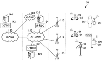
- FIG. 2 shows a communication system 70 including the first slice to the fourth slice.
- the first slices are the vehicles 82 and 84 equipped with the in-vehicle devices 92 and 94 capable of 5G wireless communication, the infrastructure camera 88 equipped with the wireless communication device 98, and the radio provided in the traffic light. It is a slice defined to include a traffic signal controller 90 provided with a communication device 100, a mobile phone 96 included in a pedestrian 86, and the like, and to enable direct communication between them.
- the second slice is a slice that includes a plurality of base stations 110, 112, and 114, and is defined so that the communication terminals included in the first slice communicate with each other.
- the third slice includes metro NWs 120 and 122 and edge servers 126 and 128 provided in distributed DCs (Data Centers) 124 and 130 connected to them, and each communication terminal is a base station. Slices defined to be able to communicate with them via 110, 112, 114, etc.
- the metro NW is a communication network constructed to connect buildings, social facilities, houses, etc. within a limited range such as for each city.
- the base stations 110, 112, 114 and the like are connected to any of the edge servers such as the edge servers 126 and 128, respectively.
- Edge servers 126, 128, etc. are so called because they are located on the outermost side of the system connected by the network and are servers connecting the network system and the rest.
- the fourth slice includes the core NW140 capable of communicating with a plurality of metro networks, and the core server 144 provided in the core DC 142 connected to the core NW140 is the edge server 126, 128, etc., and each metro network. It is possible to communicate with the communication device connected to.
- the above-mentioned traffic condition bird's-eye view map is constructed and maintained for a specific range on the edge server 128 or the like.
- Each communication terminal belonging to the first slice transmits sensor data or the like detected by the sensors provided therein to, for example, the edge server 126.
- the edge server 126 reconstructs the actual road conditions in the virtual space by integrating the sensor data, and creates and maintains the traffic condition bird's-eye view map 52.
- the edge server 126 transmits information for supporting the operation or the like to each communication terminal based on the traffic condition bird's-eye view map 52 maintained in this way.
- the in-vehicle / outside cooperation device is an in-vehicle network for data transfer, a wireless communication device that wirelessly communicates data with the outside of the vehicle, and an in-vehicle / outside cooperation device used in a vehicle equipped with a plurality of sensors.
- the transmission delay of the sensor data between the data receiving unit that receives the sensor data from the plurality of sensors via the in-vehicle network and the end from each of the plurality of sensors to a predetermined device that can be communicated by the wireless communication device.
- the end-to-end delay time estimation unit that estimates the time
- the value determination unit that determines the value of the sensor data output by the plurality of sensors based on the vehicle condition and the conditions of the plurality of sensors
- the delay time estimation unit estimate the time.
- a selection unit that selects a part of the sensor data based on the transmission delay time and the value determined by the value determination unit, and transmits a copy of the selected sensor data to a predetermined device via a wireless communication device. And include.
- the in-vehicle / external cooperation method includes an in-vehicle network for data transfer, a wireless communication device that wirelessly communicates data with the outside of the vehicle, and sensors from a plurality of sensors in a vehicle equipped with a plurality of sensors.
- a plurality of steps in which the computer estimates the transmission delay time of sensor data between the ends to a predetermined device that can be communicated by the wireless communication device, and the computer is based on the state of the vehicle and the states of the plurality of sensors.
- the transmission delay time estimated in the step of estimating the transmission delay time by the computer and the value determined by the step of determining the value. A part of the above is selected, and a step of transmitting a copy of the selected sensor data to a predetermined device via a wireless communication device is included.
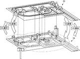
- FIG. 1 is a diagram schematically showing the relationship between the actual road condition and the road condition bird's-eye view map.
- FIG. 2 is a diagram showing a schematic configuration of the communication system shown in Patent Document 1.
- FIG. 3 is a diagram showing a schematic configuration of a traffic support system according to the first embodiment of this disclosure.
- FIG. 4 is a block diagram showing a configuration of elements related to the traffic support system in the vehicle according to the first embodiment of the disclosure.
- FIG. 5 is a block diagram showing a configuration of an edge server, which is a traffic support server that communicates with a vehicle according to the first embodiment of the disclosure.
- FIG. 6 is a block diagram schematically showing a configuration for communication of vehicle sensors and sensor data according to the first embodiment.
- FIG. 7 is a block diagram showing a schematic hardware configuration of an in-vehicle / external cooperation unit used in the vehicle according to the first embodiment shown in FIG.
- FIG. 8 is a diagram showing data required for in-vehicle / out-of-vehicle cooperation stored in the memory in the in-vehicle / out-of-vehicle cooperation unit shown in FIG. 7.
- FIG. 9 is a diagram showing an example of the stored contents of the sensor data set table shown in FIG.
- FIG. 10 is a diagram showing an example of the sensor priority policy table shown in FIG.
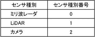
- FIG. 11 is a diagram showing the correspondence between the sensor type and the sensor type number in a table format in the vehicle according to the first embodiment.
- FIG. 12 is a diagram showing the correspondence between the sensor position type indicating the position of the sensor mounted on the vehicle and the sensor position type number in a table format.
- FIG. 13 is a schematic view showing an example of the mounting position of the camera in the vehicle.
- FIG. 14 is a diagram for explaining the priority of the sensor based on the value of the sensor data.
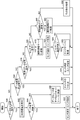
- FIG. 15 is a flowchart showing a control structure of a program for controlling communication from a vehicle, which is executed by the traffic support server according to the first embodiment of the disclosure.
- FIG. 16 is a flowchart showing a control structure of a program for controlling transmission of sensor data, which is executed by an in-vehicle device mounted on a vehicle in the traffic support system according to the first embodiment.
- FIG. 17 is a flowchart showing a control structure of a program for estimating transmission delay, which is executed by an in-vehicle device mounted on a vehicle in the traffic support system according to the first embodiment.
- FIG. 18 is a flowchart showing a control structure of a program for updating the priority policy of the sensor, which is executed by the in-vehicle device mounted on the vehicle in the traffic support system according to the first embodiment.
- FIG. 19 is a flowchart showing a control structure of a program that realizes sensor data selection and switch setting processing executed by an in-vehicle device mounted on a vehicle in the traffic support system according to the first embodiment.
- FIG. 20 is a block diagram showing a schematic configuration of the traffic support system according to the second embodiment of the disclosure.
- FIG. 21 is a block diagram showing the configuration of elements related to the traffic support system in the vehicle according to the second embodiment of the disclosure.
- FIG. 22 is a flowchart showing a control structure of a program for controlling transmission of sensor data, which is executed by an in-vehicle device mounted on a vehicle in the traffic support system according to the second embodiment.
- a traffic situation bird's-eye view map 52 can be constructed and maintained by a communication system as disclosed in Patent Document 1. Dynamic information and caution information regarding traffic obtained from the traffic situation bird's-eye view map 52 are transmitted to each communication terminal. As a result, for example, in a vehicle equipped with such a communication terminal, the road condition can be known when necessary, which can be useful for traffic safety.
- the first issue is how to deal with the dynamic fluctuation of the transmission capacity from the vehicle to the traffic support server such as the edge server.
- the transmission capacity may fluctuate greatly due to 4G / 5G area switching and shadowing.
- the transmission capacity may fluctuate significantly due to changes in the internal state of the vehicle (in-vehicle network, CPU (Central Processing Unit) resource load state), and the state of the traffic support server. Traffic support systems also need to respond appropriately to such dynamic fluctuations in transmission capacity.
- the second issue is the selection of sensor data. When all the sensor data cannot be transmitted from the vehicle to the traffic support server due to the fluctuation of the transmission capacity, it becomes necessary to select and transmit a part of the sensor data. For that purpose, it is necessary to determine what kind of sensor data should be transmitted from the vehicle to the traffic support server for the most efficiency.
- Patent Document 2 described above proposes a technique for switching the type, resolution, and frame rate of an image of a camera mounted on a vehicle according to a change in transmission capacity.
- the state inside the in-vehicle device at the time of performing such control is not taken into consideration.
- what kind of condition sensor should be selected according to various situations in which the vehicle is placed, that is, the value of the sensor data is not considered.
- Patent Document 3 discloses a technique for determining the priority when transmitting a data sample from a vehicle to a server based on the value of the data sample.
- the value of a data sample is calculated based on a data value map in a table called a data value table. Prioritize sending data samples to the server based on the calculated value.
- the data value map is determined based on the purpose of using the data sample in the server, for example, and is transmitted to the vehicle at any time.
- the vehicle receives the data value map, the vehicle updates the existing data value map with the received data. Therefore, from the standpoint of the server, it is possible to collect data from the vehicle with a priority according to the purpose of the data.
- Patent Document 3 does not disclose a technique for changing the method of calculating the value of data in real time based on the situation in which the vehicle is placed.
- the value of data does not change depending on the application, but the priority of data to be transmitted to the server should always be processed in real time according to the vehicle and the surrounding conditions of the vehicle. ..
- Patent Document 3 does not disclose such a technique.
- the purpose of this disclosure is to set the priority of data transmission according to the change in transmission capacity and the situation of the vehicle and its surroundings so that traffic support by a predetermined device such as a traffic support server can be effectively performed. It is to provide an in-vehicle / external cooperation device and a method.
- the vehicle-in-vehicle / external cooperation device is a vehicle used in an in-vehicle network for data transfer, a wireless communication device that wirelessly communicates data with the outside of the vehicle, and a vehicle equipped with a plurality of sensors.
- Sensor data between the data receiving unit which is an internal / external cooperation device and receives sensor data from a plurality of sensors via the in-vehicle network, and the end of each of the plurality of sensors to a predetermined device capable of communicating by a wireless communication device.
- An end-to-end delay time estimation unit that estimates the transmission delay time, a value determination unit that determines the value of sensor data output by a plurality of sensors based on the vehicle condition and the conditions of a plurality of sensors, and a delay time estimation unit. A part of the sensor data is selected based on the transmission delay time estimated by the unit and the value determined by the value determination unit, and a copy of the selected sensor data is transmitted to a predetermined device via a wireless communication device. Includes a selection section to be used.
- the end-to-end delay time estimation unit estimates the transmission delay time of sensor data between the ends from each of a plurality of sensors mounted on the vehicle to a predetermined device.
- the value determination unit determines the value of the sensor data output by the plurality of sensors based on the state of the vehicle and the states of the plurality of sensors.
- the selection unit selects a part of the sensor data based on the transmission delay time estimated by the delay time estimation unit and the value determined by the value determination unit, and makes a copy of the selected sensor data via a wireless communication device. And send it to the specified device. Estimate the transmission delay time between the ends of the sensor to a particular device, including the delay time in the in-vehicle network, and determine based on the estimated transmission delay time and the value determined for each of the sensor data.
- Select the sensor data to send to the device While following the fluctuation of the transmission capacity by the wireless communication device, considering the transmission delay time between the end from the sensor to the predetermined device, select the sensor data that can be effectively used in the predetermined device and cooperate inside and outside the vehicle. Since the device transmits, it is possible to provide an in-vehicle / external cooperation device that can maximize the function of a predetermined device while maximizing the transmission capacity.
- the end-to-end delay time estimation unit includes a network transmission time estimation unit that estimates the network delay time for each sensor until sensor data from a plurality of sensors reaches the data reception unit via the in-vehicle network, and data reception.
- the processing time estimation unit that estimates the processing time required for processing until the sensor data that reaches the unit is input to the wireless communication device, and the wireless communication delay time required for the sensor data to be transmitted from the wireless communication device to a predetermined device.
- the wireless communication delay time estimation unit for estimating the above and the delay time calculation unit for calculating the transmission delay time based on the data amount, network delay time, processing time, and wireless communication delay time of each of the plurality of sensors may be included. ..
- the processing time required for processing the sensor data that has reached the data receiver to be input to the wireless communication device and the wireless communication delay time required for the sensor data to be transmitted from the wireless communication device to a predetermined device is estimated for each sensor, and the transmission delay time between the ends is calculated based on these. Since the transmission delay time between the ends is calculated in consideration of the transmission delay time of the in-vehicle network, the amount of data that can be transmitted to a predetermined device within the allowable delay time can be estimated more accurately, and the sensor data to be transmitted can be selected. You can do it more accurately.
- the value determination unit includes an infrastructure detection range estimation unit that estimates the detection range of infrastructure sensors existing in the vicinity of the vehicle based on the position of the vehicle, and a plurality of sensors based on the position and attitude of the vehicle.
- a value setting unit that estimates the detection range and sets the value of the sensor data from each sensor so that the smaller the area that overlaps with the detection range of the infrastructure sensor estimated by the infrastructure detection range estimation unit, the greater the value. It may be included.
- the sensor data from the sensor with a large detection range that overlaps with the detection range of the infrastructure sensor has low utility value in a predetermined device.
- the sensor data is preferentially selected and transmitted to a predetermined device. Since high-value sensor data is transmitted to a predetermined device within a limited transmission capacity, the predetermined device can perform stable processing based on the sensor data regardless of fluctuations in the transmission capacity.
- the infrastructure detection range estimation unit includes an infrastructure detection range update unit that repeatedly updates the estimated detection range of the infrastructure sensor existing in the vicinity of the vehicle based on the position of the vehicle at predetermined time intervals, and includes a value setting unit. Is the sensor data from each sensor so that the smaller the area that overlaps with the detection range of the infrastructure sensor updated by the infrastructure detection range update unit, the greater the value, based on the position and attitude of the vehicle at predetermined time intervals. It may include a value update unit that repeatedly updates the value of.
- the detection range of the infrastructure sensor is updated at predetermined time intervals.
- the value of the sensor data is also updated at predetermined time intervals based on the position and attitude of the vehicle and the updated detection range of the infrastructure sensor. Therefore, the value of each sensor of the vehicle is updated at least at predetermined time intervals in accordance with the movement of the vehicle and the communication environment around the vehicle.
- high-value sensor data is transmitted to a predetermined device regardless of the movement of the vehicle, changes in the communication environment around the vehicle, and the like. Therefore, regardless of changes in the environment, the predetermined device can perform stable processing.
- Each of the plurality of sensors is classified into one of a plurality of sensor types, and the infrastructure detection range estimation unit determines the detection range of the infrastructure sensors existing in the vicinity of the vehicle based on the position of the vehicle.
- the sensor type detection range estimation unit that estimates for each sensor type of the sensor may be included, and the value setting unit may include the sensor type among the plurality of sensors based on the position and attitude of the vehicle for each of the plurality of sensor types.
- the detection range of each sensor belonging to the It may include a sensor type sensor data value setting unit that sets the value of sensor data from a sensor belonging to the sensor type.
- the value setting unit sets the value of the sensor data for each sensor type, it is possible to select the sensor data that is effective for processing a predetermined device by making more effective use of the transmission capacity.
- the vehicle interior / external cooperation device may further include a sensor data set storage unit that stores information designating a plurality of sensor data sets together with an identifier of each sensor data set, and the plurality of sensor data sets may include a plurality of sensors. For each type, it may include information that specifies the number to be selected from a plurality of sensors and the data format related to the amount of data of the sensor data from the sensor, and the vehicle interior / external cooperation device may further include any of the identifiers from the predetermined device.
- the sensor data set reading unit that reads the sensor data set information corresponding to the identifier from the sensor data set storage unit, and the sensor data set information read by the sensor data set reading unit.
- each of the plurality of sensor types is specified by the information of the sensor data set read by the sensor data set reading unit.
- the sensor data selection unit that selects the sensor data from a certain number of sensors in order from the one with the highest value and the sensor data selected by the sensor data selection unit are transferred with priority over other sensor data. It may include a network setting unit for setting a network.
- the number of sensors specified by the sensor data set is selected in order from the one with the highest value of the sensor data for each sensor type. ..
- a valuable predetermined number of sensor data is transmitted to a predetermined device based on the designation by the sensor dataset. As a result, in the predetermined device, stable processing can be executed by effectively utilizing the sensor data.
- the vehicle is further equipped with a vehicle control device that controls the vehicle using sensor data from a plurality of sensors, and the vehicle control device uses sensor data received from the plurality of sensors via a network.
- a vehicle control device that controls the vehicle using sensor data from a plurality of sensors, and the vehicle control device uses sensor data received from the plurality of sensors via a network.
- An automatic driving ECU Electric Control Unit that automatically drives the vehicle may be included.
- the automatic driving ECU operates based on sensor data from a plurality of sensors mounted on the vehicle. Since any of these sensor data is selected by the vehicle interior / external cooperation device and transmitted to a predetermined device, the sensor data can be shared between the automatic driving ECU and the predetermined device, and the automatic driving of the vehicle and the predetermined device can be efficiently performed. Processing can be executed.
- the vehicle control device is a remote control ECU that controls the vehicle according to a predetermined remote control command, and an external remote control device that receives sensor data received from a plurality of sensors via a network via a wireless communication device. It may include a sensor data transmission unit to be transmitted to the remote control device and an input device for inputting a remote control command received from the remote control device via a wireless communication device to the remote control ECU.
- the remote control device operates based on sensor data received from a plurality of sensors mounted on the vehicle, and transmits a remote control command to the remote control ECU. Any of the sensor data transmitted to the remote control device is selected by the vehicle interior / external cooperation device and transmitted to a predetermined device. Therefore, the sensor data can be shared between the remote control device and the predetermined device, and the remote control of the vehicle and the processing of the predetermined device can be efficiently performed.
- the in-vehicle / external cooperation method includes an in-vehicle network for data transfer, a wireless communication device that wirelessly communicates data with the outside of the vehicle, and a plurality of sensors in a vehicle equipped with a plurality of sensors.
- This is an in-vehicle / out-of-vehicle cooperation method in which the inside and outside of the vehicle are linked by transmitting the sensor data from the computer to a predetermined external device, and the computer receives the sensor data from a plurality of sensors mounted on the vehicle via the in-vehicle network.
- the steps by which the computer estimates the transmission delay time of sensor data between the ends to a predetermined device that can be communicated by the wireless communicator, and the computer's vehicle condition and the condition of multiple sensors Based on the transmission delay time estimated in the step of determining the value of the sensor data output by the plurality of sensors and the step of estimating the transmission delay time by the computer, and the value determined by the step of determining the value. , A step of selecting a part of the sensor data and transmitting a copy of the selected sensor data to a predetermined device via a wireless communication device.
- the transmission delay time of the sensor data between the ends is estimated.
- the value of the sensor data output by the plurality of sensors is determined based on the condition of the vehicle and the condition of the plurality of sensors.
- a portion of the sensor data is selected and a copy of the sensor data is transmitted to a given device via the wireless communicator. ..
- the sensor data to be sent to the device is selected. While following the fluctuation of the transmission capacity due to wireless communication, the sensor data that can be effectively used by the predetermined device is selected and transmitted in consideration of the transmission delay time between the end from the sensor to the predetermined device. It is possible to provide an in-vehicle / external cooperation method that can maximize the functions of a predetermined device while maximizing the transmission capacity.
- the priority of data transmission is determined according to the change in transmission capacity and the situation of the vehicle and its surroundings so that traffic support by a predetermined device such as a traffic support server can be effectively performed. It is possible to provide an in-vehicle / external cooperation device and a method capable of the above.
- FIG. 3 shows a schematic configuration diagram of the traffic support system according to this disclosure.
- this traffic support system like the one described in Patent Document 1, includes vehicles 82 and 84, an infrastructure sensor (not shown), a mobile phone owned by a pedestrian, and the like, and via these and a base station 110. It includes an edge server 128, which is a traffic support server that performs processing for constructing and maintaining a communication status map 152 and a traffic status bird's-eye view map 150.
- the communication status map 152 is, for example, a high-definition map prepared in advance for traffic support divided into a grid consisting of a plurality of compartments having sides of a certain length, and the communication status in each compartment is recorded. ..
- the communication status for each section is represented by the central position of the section and the representative value of the transmission speed of the data transmitted from the vehicle in the section to the traffic support server during a certain period in the past.
- NS In order to calculate the representative value of the transmission speed in the past fixed period, the data related to the transmission speed of the data received by the traffic support server during the past fixed period is also accumulated.
- the representative value of the transmission speed typically, the average transmission speed, the mode value of the transmission speed, the median value of the transmission speed, these representative values calculated from the data excluding the predetermined number of upper and lower parts, etc. are used. be able to.
- a traffic situation bird's-eye view map is a high-definition map prepared in advance in a virtual space for a certain area, and the positions, speeds, attributes, etc. of moving objects such as vehicles and pedestrians and fixed objects such as buildings existing in the area. Is memorized in relation to the identification number.
- the traffic situation bird's-eye view map is obtained from the data transmitted from the so-called infrastructure sensors installed in the area and the in-vehicle sensors mounted on the vehicle, and from predetermined sources regarding road construction, accidents, installation locations of infrastructure sensors and their attributes, etc. It is built on information.
- the first embodiment will be described by taking as an example how the sensor data is transmitted from the vehicle 82 to the edge server 128.
- the vehicle 82 collects sensor data from various sensors 170, an automatic driving ECU (Electronic Control Unit) 172 for automatic driving control of the vehicle, and sensor data from these sensors 170, and communicates with the automatic driving ECU 172.
- the vehicle-mounted device 92 for controlling the automatic driving ECU 172 and the vehicle-mounted communication device 162 used when the vehicle-mounted device 92 communicates with an element outside the vehicle such as an edge server 128 and another vehicle are included.
- the in-vehicle device 92 is connected to the sensor 170 and the automatic driving ECU 172 via the network switch (NSW) 160 for in-vehicle communication to which the sensor 170 and the automatic driving ECU 172 are connected, and to the sensor 170 and the automatic driving ECU 172 via the NSW 160, while the external communication device 162.
- the sensor data from the sensor 170 is transmitted to the outside via the sensor 170, and the operating state of the automatic driving ECU 172 etc. is linked by using the information collected from the sensor etc. in the vehicle and the data received from the outside via the external communication device 162.
- the vehicle interior / external cooperation unit 164 is a process for collecting sensor data and a process for transmitting the sensor data to the outside in response to an instruction from the edge server 128 and a change in the situation of the vehicle 82.
- the in-vehicle device 92 shown in FIG. 4 includes the NSW 160 and the in-vehicle / outside cooperation unit 164, but may be one in-vehicle device including the automatic driving ECU 172 and / or the out-of-vehicle communication device 162.
- the in-vehicle device 92 may be realized as a semiconductor integrated circuit such as an ASIC (Application-Specific Integrated Circuit), a system LSI (Large Scale Integration), or a device in which a plurality of semiconductor integrated circuits are mounted on a substrate.
- ASIC Application-Specific Integrated Circuit
- LSI Large Scale Integration
- the sensor data from the sensor 170 is transmitted to the automatic driving ECU 172, but as shown by the arrow 174, a part of the sensor data is selected by the vehicle interior / external cooperation unit 164 and transmitted to the edge server 128.
- the vehicle-internal / external cooperation unit 164 determines the transmission capacity between the vehicle-external communication device 162 and the edge server 128, the processing time in the network in the vehicle 82, the in-vehicle / external cooperation unit 164 and the like, and the vehicle 82.
- the method of selecting the sensor data that allows the edge server 128 to construct the traffic situation bird's-eye view map 150 most efficiently according to the situation will be described.
- the transmission speed of the in-vehicle network as conventionally used will not be sufficient, and it is being considered to use a network having a gigabit class transmission speed for the in-vehicle network.
- the in-vehicle devices of the vehicle 82 communicate with each other via such a network.
- Existing technologies related to networks connecting computers can be applied to such networks, and it is expected that the cost for constructing an in-vehicle network will be reduced accordingly.
- TCP-IP Transmission Control Protocol-Internet Protocol
- the edge server 128 is a signal from a plurality of infrastructure sensor equipment 180 (including any combination of camera, millimeter wave radar and LiDAR) as described above and a sensor (camera) mounted on the vehicle 82. , LiDAR, and any combination of millimeter-wave radar) includes a reception processing unit 210 for receiving signals from 170.
- Each of the infrastructure sensor equipment 180 communicates with the infrastructure sensor 190, which is composed of an arbitrary combination of a camera, a millimeter-wave radar, and LiDAR, for transmitting a signal output by the infrastructure sensor 190 to a reception processing unit 210 of the edge server 128. Includes device 192 and.
- the vehicle 82 also includes a sensor 170 composed of a camera, LiDAR or millimeter wave radar, and an out-of-vehicle communication device 162 that transmits at least a part of the signal output by the sensor 170 to the reception processing unit 210 of the edge server 128. ..
- the edge server 128 further determines, tracks, and tracks the position of each moving object in a predetermined first cycle by analyzing the ranging signals from LiDAR, millimeter-wave radar, and the like among the signals received by the receiving processing unit 210.
- Includes an attribute detection unit 216 that determines the attributes and positions of moving objects such as vehicles and people in the image in a predetermined second cycle longer than the first cycle by performing the analysis.
- the edge server 128 further includes an attribute storage unit 218 for storing the attribute 217 output by the attribute detection unit 216, a moving object tracking result 213 stored in the moving object tracking result storage unit 214, and an attribute stored in the attribute storage unit 218.
- 217 is repeatedly integrated in a cycle shorter than the second cycle, and the integrated processing unit 224 that outputs the traffic condition bird's-eye view map 225, which is the analysis result after the integration, and the traffic condition bird's-eye view map 225 output by the integrated processing unit 224 are accumulated. Includes a traffic situation bird's-eye view map storage unit 226 to be stored.
- the moving object tracking result 213, the attribute 217, and the traffic condition bird's-eye view map 225 are calculated at predetermined times, respectively, but the analysis results calculated in the past fixed time are also recorded as the history of the moving object tracking result storage unit 214, the attribute storage unit 218, and the attribute storage unit 218, respectively. It is stored and stored in the traffic situation bird's-eye view map storage unit 226.
- the integrated processing unit 224 performs the integrated processing
- the history of the traffic condition bird's-eye view map 225 which is the past integrated analysis result accumulated in the traffic condition bird's-eye view map storage unit 226, may be referred to.
- the edge server 128 further obtains vehicle information including vehicle attributes such as identification information of the vehicle to be managed, mounted sensor information, position, speed, and vehicle size based on the signal received from each vehicle by the reception processing unit 210. It includes a vehicle tracking unit 220 for obtaining and a vehicle information storage unit 222 for storing vehicle information 221 of each vehicle analyzed by the vehicle tracking unit 220.
- vehicle attributes such as identification information of the vehicle to be managed, mounted sensor information, position, speed, and vehicle size based on the signal received from each vehicle by the reception processing unit 210. It includes a vehicle tracking unit 220 for obtaining and a vehicle information storage unit 222 for storing vehicle information 221 of each vehicle analyzed by the vehicle tracking unit 220.
- the edge server 128 further collates the moving object information of the traffic situation bird's-eye view map 225 with the vehicle information 221 stored in the vehicle information storage unit 222, and in the integrated moving object information, a child or a pedestrian walking while looking at a smartphone.
- Information for traffic support such as information on moving objects with attributes that are considered dangerous, accident vehicles on the road, broken vehicles, falling objects, etc., to vehicles located within a predetermined range from the object It includes an information transmission unit 228 that performs processing such as notifying the target vehicle, and a transmission processing unit 230 for transmitting a signal for information notification by the information transmission unit 228 to the target vehicle.
- the edge server 128 further includes a high-definition map storage unit 262 that stores a high-definition map, a traffic situation bird's-eye view map stored in the traffic situation bird's-eye view map storage unit 226, and a high-definition map stored in the high-definition map storage unit 262.
- a high priority area extraction unit 240 for extracting coordinates that specify a high priority area is included.
- the high priority area is an area in which sensor data related to the area needs to be collected preferentially.
- high-priority areas for example, an area in which a number of moving objects exceeding a predetermined threshold value exists in the area, and moving objects having attributes that may cause dangerous behavior such as children are detected. Area etc. can be considered.
- the high priority area extraction unit 240 extracts the high priority area by, for example, dividing the road map into predetermined sections and determining whether or not the above conditions are met for each section. For the detection of areas where moving objects above the threshold value are gathered, multiple areas of interest (for example, intersections) are determined in advance on the road map, and it is inspected whether or not the conditions are satisfied only in those areas. You may do so.
- the edge server 128 further stores the sensor priority policy for each of the sensor priority policy storage unit 242 that stores a plurality of sensor priority policies, which will be described later, and the high priority area extracted by the high priority area extraction unit 240.
- the policy determination unit 244 determines which of the sensor priority policies stored in the unit 242 is applied according to the situation of the extracted area and the area extracted by the high priority area extraction unit 240. It includes a candidate vehicle selection unit 246 that selects a vehicle whose area is included in the detection range of the sensor as a candidate vehicle for sensor data collection. That is, in the high priority area, the edge server 128 collects sensor data from only some vehicles. Some of these vehicles are equipped with high performance sensors and transmitters. By selecting such vehicles and collecting sensor data, the edge server 128 can afford the necessary sensor data even when there are a large number of vehicles in the high priority area and the communication status may deteriorate. Can be collected.
- the sensor priority policy shows a guideline regarding what kind of sensor data is prioritized in the sensor data. For example, assume that a child is detected in an area. Such an area is referred to here as a child detection area. Children, unlike adults, can suddenly move unexpectedly. Therefore, in the child detection area, it is necessary to frequently acquire information about the position of the detected moving object. Therefore, the sensor data from a sensor that can detect the position of a moving object at high speed, such as LiDAR, is prioritized over the sensor data from a sensor that is difficult or takes a long time to detect the position of a moving object, such as a camera. Need to send to edge server 128. On the other hand, consider, for example, an area where an accident vehicle exists on the road.
- an area is called an accident area. Since the accident vehicle normally does not move, it is not necessary to send the position coordinates to the edge server 128 with high frequency. In addition, in order to know the situation of the accident, it is easier for the driver of each vehicle to understand the situation by distributing it to each vehicle in the form of an image like a camera. Therefore, it is better to give priority to the camera over LiDAR in such an area. In this way, the sensor priority policy provides a basic guideline as to what kind of sensor should be preferentially transmitted to the edge server 128 depending on the situation of each area.
- each vehicle transmits sensor data to the edge server 128 except in the high priority area, and at that time, the coordinates for specifying the detection range by the sensor of the vehicle (basic position of the vehicle). (Relative coordinates to) is transmitted as vehicle information.
- a candidate vehicle can be selected by calculating the absolute coordinates of the range that can be detected by the sensor of each vehicle from these coordinates and the coordinates of the basic position of the vehicle, and collating the coordinates with the coordinates of each area.
- the edge server 128 further transmits a sensor priority policy determined by the policy determination unit 244 for each of the candidate vehicles selected by the candidate vehicle selection unit 246, and each vehicle is sent to the edge server 128 according to the sensor priority policy.
- the data set inquiry unit 250 for inquiring the sensor data set table consisting of the sensor data set at the time of transmission, and the sensor data set table obtained from each candidate vehicle for the inquiry by the data set inquiry unit 250 for each vehicle.
- the edge server 128 selects and selects the vehicle that can transmit the most efficient sensor data to create a traffic situation bird's-eye view map.
- a vehicle selection unit 252 that transmits an instruction requesting transmission of sensor data to the vehicle, and an inquiry transmission / reception unit 254 for wireless communication of communication with each vehicle by the data set inquiry unit 250 and the vehicle selection unit 252. include.
- Various criteria can be considered from the designer's point of view regarding the transmission of the most effective sensor data for creating a traffic situation bird's-eye view map. For example, it can be considered that the most important data from the viewpoint of driving assistance of traffic participants, that is, data valuable for accident prevention, is transmitted to the edge server 128 at a sufficient transmission speed for that purpose. .. From another point of view, it can be considered that the sensor data is transmitted to the edge server 128 so that the content of the traffic condition bird's-eye view map can follow the actual change as accurately as possible and at a sufficient speed.
- the edge server 128 further transmits data from each section to the edge server 128 based on sensor data, vehicle information, and the like received by the reception processing unit 210 from the vehicle in each section of the high-definition map.
- High-definition stored in the high-definition map storage unit 262 based on the line speed information storage unit 256 that extracts the line speed information of the above and stores it for a predetermined time and the line speed information stored in the line speed information storage unit 256.
- the communication status map management unit 258 for creating and managing the communication status map showing the communication status
- the communication status map storage for storing the communication status map created by the communication status map management unit 258. Including part 260.
- the communication status map is referred to.
- the inquiry transmission / reception unit 254 may use the same hardware as the reception processing unit 210 and the transmission processing unit 230.
- Whether or not the sensor priority policy is met can be quantitatively determined, but in this embodiment, it is determined in advance using a sensor data set table corresponding to each sensor priority policy as described later.
- the sensor dataset table can be created based on subjective criteria, transmission capacity such as line speed, number of high priority areas that the traffic situation bird's-eye view map is paying attention to, the position of vehicles in that area, and each vehicle.
- Formulate a mathematical formula from various factors such as the capacity of the transmission equipment possessed by the vehicle, the number of moving objects existing in the area, etc., and compare the values obtained by applying these factors to this mathematical formula. You can also. However, in reality, it is realistic to use the method using the sensor data set table described below.
- a sensor data set table is prepared in advance for each vehicle.
- Each vehicle responds to an inquiry from the data set inquiry unit 250 and transmits these sensor data set tables to the data set inquiry unit 250.
- the sensor data set table will be described later with reference to FIG.
- each vehicle or infrastructure sensor may have at least a sensor that detects the position of an object such as LiDAR or a millimeter-wave radar and a sensor that acquires an image such as a camera.
- intersections with many moving objects and areas with children are both extracted as high-priority areas of the same level.
- this disclosure is not limited to such embodiments.
- the intersections, etc. are rather wide areas, and the areas where children are detected are narrow areas, and their characteristics are different. Therefore, only one of them may be extracted. Further, a wide area may be extracted first, and a narrow area may be extracted in the wide area.
- the definition (resolution) differs depending on the product specifications, and the amount of sensor data also differs. Therefore, it is necessary to prepare a sensor data set table that conforms to each sensor priority policy by fully considering the type of the target sensor, the definition of the sensor data, and the transmission interval.
- FIG. 6 schematically shows the sensor arrangement and network configuration of the vehicle 82.
- the vehicle 82 has an in-vehicle network 288 having a gigabit-class transmission speed to which the above-mentioned in-vehicle / external cooperation unit 164 and the automatic driving ECU 172 are connected, and the right front portion, the left front portion, and the right rear portion of the vehicle 82.
- And sensor units 280, 282, 284 and 286 mounted on the left rear, respectively.
- Each of the sensor units 280, 282, 284 and 286 includes a millimeter wave radar, a camera, and LiDAR.
- the vehicle-mounted network 288 is located between four Gigabit class network switches 292, 294, 296 and 298, respectively, to which sensors belonging to the same sensor unit are connected, and two network switches 292 and 294 in front of the vehicle. It includes a first multi-giga switch 300 for bridging and a second multi-giga switch 302 for bridging between the two network switches 296 and 298 at the rear of the vehicle and connected to the first multi-giga switch 300.
- the vehicle interior / external cooperation unit 164 is connected to the network switch 292, and the automatic driving ECU 172 is connected to the network switch 294.
- the TCU (Telematics Control Unit) 290 corresponding to the external communication device 162 shown in FIG. 4 is connected to the network switch 292 together with the internal / external cooperation unit 164.
- the sensor units 280, 282, 284 and 286 are arranged at different positions on the vehicle. Therefore, the value of the sensor data from these sensor units may differ depending on the situation in which the vehicle is placed, as will be described later.
- FIG. 7 shows the hardware configuration of the vehicle interior / external cooperation unit 164.
- the vehicle interior / external coordination unit 164 includes a microprocessor 320.
- the microprocessor 320 includes a bus 342, a CPU 340 connected to the bus 342, a ROM (Read-Only Memory) 344, a RAM (Random Access Memory) 346, a DMAC (Direct Media Access Controller) 348, and an input / output I / F. (Interface) 352, a timer 350 and a DMAC348, a timer 350 and an interrupt controller 354 connected to the input / output I / F 352 and causing an interrupt to the CPU 340 in response to a signal from these.
- ROM Read-Only Memory
- RAM Random Access Memory
- DMAC Direct Media Access Controller
- the interrupt controller 354 periodically causes the CPU 340 to interrupt the timer based on the time taken by the timer 350.
- the interrupt controller 354 also causes an input / output interrupt to the CPU 340 when there is an input / output from the outside of the input / output I / F 352. Further, when the data transfer by the DMAC348 is completed, the interrupt controller 354 causes the CPU 340 to interrupt in response to the signal from the DMAC348.
- FIG. 8 shows a RAM 346 stored in the vehicle interior / external cooperation unit 164 shown in FIG. 4 for vehicle interior / external cooperation. All of these fixed data are stored in the ROM 344 shown in FIG. 7 and loaded into the RAM 346 when the program is executed by the CPU 340. Other data are dynamically generated by the CPU 340 and stored in the RAM 346 when the program is executed.
- the RAM 346 is a sensor data set table 402 that stores a plurality of mounted sensor information 400, which is information about a sensor mounted on the vehicle 82, and a plurality of sensor data sets to be transmitted to the outside by the vehicle 82. , When a sensor data set for transmission to the outside is specified, a plurality of sensor priority policies indicating how to determine the priority for each type of sensor according to the vehicle conditions, etc. are stored.
- Sensor priority policy table 404 high-definition map data 406 for navigation system (not shown) mounted on vehicle 82, vehicle internal / external cooperation unit for transmission from various sensors mounted on vehicle 82 to edge server 128
- the sensor data storage area 408 for temporarily storing the sensor data transmitted to 164 and the sensor data set to be transmitted are determined and the sensor priority is determined, the priority according to the priority is determined.
- the packet priority policy is information for specifying the packet priority that can be set for each switch, the number of queues for each packet priority, the packet transfer frequency for each priority, and the like. Using this, a packet transfer policy for each priority is set for each packet, and information that specifies the priority is stored in the packet header of the sensor data, so that each switch executes transfer processing according to the priority. do.
- FIG. 9 shows an example of the sensor data set table 402 stored in the RAM 346.
- the sensor data set table 402 stores eight sensor data sets represented by identification numbers (IDs) 0 to 7 in the first column in this example.
- IDs identification numbers
- the identification number is defined in this embodiment so that the small amount of data transmitted when each sensor data set is selected is small, and the large amount is large.
- a LiDAR, a millimeter wave radar, and a camera are assumed as sensors.
- the second column of FIG. 9 represents the nature of the data transmitted by each sensor dataset.
- the resolution or compression rate at the time of transmission of the sensor data of the LiDAR, the millimeter wave radar, and the camera is shown in order from the left.
- the image data of the camera is an SD (Standard Definition) image.
- the SD image is an image composed of 720 ⁇ 480 pixels or 720 ⁇ 576 pixels.
- a full HD image is an image composed of 1900 ⁇ 1080 pixels.
- the "HD image” such as the identification numbers 3 and 6 is an image composed of 1280 ⁇ 780 pixels. These images are images obtained from the same camera, and the central portion thereof is common to images of any resolution. That is, the HD image is an image of the central portion of the full HD image, and the SD image is an image of the central portion of the HD image.
- the third column is the data transmission interval (data interval).
- this data interval is also set for each ID and each sensor.
- FIG. 9 for example, it is shown that the LiDAR and the millimeter wave radar transmit the identification number 1 10 times per second, and do not transmit the camera image.
- both the LiDAR and the millimeter-wave radar are supposed to transmit the full HD image three times per second and the camera image three times to the edge server 128, respectively.
- the rightmost column shows how many sensors of each type mounted on the vehicle will transmit data. For example, for identification number 1, it indicates that 4 data are transmitted for both LiDAR and millimeter-wave radar, and that the camera is not used. Regarding the identification number 4, the LiDAR and the millimeter-wave radar both transmit the data of four sensors, while the camera also has four. On the other hand, in the case of the identification number 6, the LiDAR and the millimeter wave radar are the same four, but the camera uses only two.
- the total amount of data to be transmitted can be controlled by specifying the resolution or compression rate of each sensor, the transmission interval, and the number of sensors to be used for each identification number. That is, by specifying the sensor data set ID, the content and total amount of sensor data transmitted from the vehicle to the edge server 128 can be controlled.
- the child detection area and the accident area are mentioned as the nature of the area, but the nature of the area is not limited to these. For example, even adults need to be as careful as children when they are operating smartphones. The same applies when a two-seater or three-seater bicycle is detected. Further, as an example in which the camera image is prioritized, for example, a failed vehicle is stopped in a place where many parked vehicles exist, a place where traffic jams exist for a long time, or a position where the vehicle does not normally stop. Areas (failed vehicle areas) and the like can be mentioned.
- each vehicle transmits the sensor data set table of each vehicle to the edge server 128.
- the edge server 128 refers to the sensor data set table of each vehicle, determines from which vehicle the sensor data set corresponding to which identification number is to be transmitted, and sensors the vehicle. Request the transmission of sensor data by specifying the identification number of the data set.
- the available transmission capacity the delay time of data communication by the network in the own vehicle, the processing time by the CPU installed in the in-vehicle device, the transmission delay to the edge server 128, etc.
- the edge server 128 determines whether or not all of the sensor data sets corresponding to the identification numbers transmitted from the edge server 128 can be transmitted within the allowable delay time. If the judgment is affirmative, transmission of the specified sensor data set is started. If the determination is negative, the edge server 128 is requested to lower the identification number by 1, and the transmission of sensor data is not started. When the vehicle responds to lower the identification number by 1, the edge server 128 selects another vehicle and requests that vehicle to transmit a specific sensor data set. When the transmission of the sensor data set from any vehicle is started, the communication is continued, and if all the vehicles request to lower the identification number by 1, the amount of sensor data to be transferred is reduced and the sensor data is reduced. A value one lower than the number specified earlier is specified as the identification number of the set, and the vehicle selection and the sensor data transmission request are repeated again. Details of this procedure will be described later with reference to FIG.
- FIG. 10 shows an example of the sensor priority policy table 404 defined for the identification number of the sensor data set. What is shown in FIG. 10 corresponds to the identification number 3 or 6 in FIG.
- the number of sensors in the sensor data set of the identification number 3 in FIG. 9 is “4, 4, 2”. That is, there are four millimeter-wave radars and four LiDARs, and two cameras.
- FIG. 10 assuming that there are four millimeter-wave radars # 0, 1, 2 and 3 as the millimeter-wave radar, these are adopted in this order.
- LiDAR and if there are LiDAR # 0, # 1, # 2 and 3, these are adopted in this order.
- the camera it is assumed that there are cameras # 0, # 1, # 2 and 3, and cameras # 2 and 3 are adopted among them. Which camera is adopted from the four cameras in this way is determined based on the value of the sensor data obtained from each camera.
- the millimeter-wave radar, LiDAR, and camera are assigned sensor type numbers 0, 1, and 2, respectively, according to the sensor type.
- sensor position type numbers are assigned according to the sensor position types (front and back, left and right). In the example shown in FIG. 12, 0 is assigned when the sensor position is forward, 1 is assigned when the sensor position is rearward, 0 is assigned when the sensor position is left, and 1 is assigned when the sensor position is right.
- the sensor position is a combination of front and back and left and right. That is, in the case of a camera, as shown in FIG.
- the front left camera 440, the front right camera 442, the rear left camera 444, and the rear right camera 446 of the vehicle 82 have the above-mentioned sensor type numbers and sensor position types.
- the following codes are assigned to each camera.
- This code it is possible to decide which one to select when only two of the four cameras are adopted.
- the method will be described below.
- the following description relates to a method of determining the magnitude of the value of image data obtained from each camera, selecting a code according to the value, and adopting a camera corresponding to the code.
- the detection range of the camera of the vehicle 520 there is little or no overlap between the detection range of the camera of the vehicle 520 and the detection range of the surrounding infrastructure cameras, and if the image data obtained by the camera behind the vehicle 520 is transmitted to the edge server 128, the overlap is very small.
- the utility value is high. Further, since the vehicle 520 is in an area where high-speed communication is possible, an HD image or a full HD image can be used as the image.
- the image behind vehicle 522 is of less value to edge server 128.
- the image in front of the vehicle 522 is of high value to the edge server 128. Since the vehicle 522 is also in an area where high-speed communication is possible, HD images or full HD images can be used.
- the value of the image from the camera that obtains an image that does not overlap with the image obtained by the infrastructure camera is set high, and the value of the image from the camera that does not obtain the image is set low, so that the high value image is obtained.
- each of the vehicles 520, 522, and 524 is equipped with four LiDARs, four millimeter-wave radars, and four cameras as shown in FIG. 6, and which sensor priority policy table 404 shown in FIG. 10 is used. It will be explained below whether to decide.
- the sensor type is represented by the code shown in FIG. 11, and the position (front and back, left and right) of each sensor is represented by the code shown in FIG. These are coded in the order of (sensor type, front / back, left / right). The same applies to sensors other than cameras.
- the rear camera is used regardless of the left or right camera. That is, two cameras out of the four cameras are adopted. Since the vehicle 520 is in an area where high-speed communication is possible, the sensor data set in this case is the identification number “6” shown in FIG. In this case, if the codes of the 12 sensors are sorted in descending order, these 12 sensors are arranged in the following order.
- the lower four of these are millimeter-wave radars, and all of them are adopted in the sensor data set of identification number 6.
- the middle four are LiDAR, and all of them are also adopted.
- the first two "211" and "210" refer to the rear camera of the vehicle 520. Since only two cameras are used in the sensor data set of the identification number 6, the upper two cameras are used, and the other cameras are not used.
- each sensor can be coded, and if the value of the front sensor is high, the code is sorted in ascending order, and if the value of the rear sensor is high, the code is sorted in descending order, so that the desired sensor can be selected.
- the entire code is sorted in ascending or descending order.
- this disclosure is not limited to such embodiments.
- the sensor can be selected based on the defined values for both front and back and left and right.
- FIG. 15 shows a control structure of a program in which the edge server 128 requests the specific vehicle in each area to transmit the sensor data and collects the sensor data by a computer in a flowchart format. This program repeatedly operates at predetermined time intervals in parallel with a program for creating a traffic situation bird's-eye view map and a program for creating a communication situation map.
- this program extracts a high priority area from the areas in charge of the edge server 128 according to the above-mentioned criteria, and the following for each area extracted in step 550.
- a period longer than that of a vehicle that transmits sensor data from within the high priority area to a vehicle that does not exist in any of the high priority areas after the step 552 that executes the process 554 and the end of the step 552 ( Includes step 556, which instructs the transmission of the sensor data in (including the case of stopping transmission) and ends the execution of the program.
- the process 554 calculates the detection range of the sensor of the vehicle from the step 570 for determining the sensor priority policy according to the nature of the area to be processed and the data transmitted from the vehicle existing in the area to be processed. , A vehicle that includes the area to be processed in the detection range of the sensor, or a vehicle that is likely to have the area to be processed in the detection range of the sensor in the near future based on the moving speed and direction of the vehicle, and a predetermined sensor is used. Sensor data based on the sensor data set table received from the vehicle according to the sensor priority policy determined in step 570 for each vehicle selected in step 572 and step 572 to select the mounted vehicle as a vehicle candidate.
- step 576 for executing the process 578 for attempting to receive the sensor data for each vehicle, and step 576.
- step 580 in which the determination is made and the control flow is branched according to the determination and the determination in step 580 is negative, the value of the sensor data set identifier to be transmitted to each vehicle is subtracted by 1. Includes step 582, which returns control to step 576.
- the process 578 transmits the identifier of the sensor data set determined in step 574 for the target vehicle, and requests the target vehicle to transmit the corresponding sensor data set.
- step 592 which determines whether or not, and branches the control flow according to the determination, and the determination in step 592 is affirmative, the sensor data is sent to other vehicles existing in the high priority area being processed. It includes step 594 of transmitting an instruction to stop transmission and step 596 of exiting the loop process of process 578 regarding the high priority area being processed.
- the determination in step 592 is negative (a request is received from the target vehicle to lower the identifier of the sensor data set by 1), the process 578 is terminated and the next vehicle among the candidate vehicles in the high priority area to be processed. Processing 578 is started for.
- the process 554 is performed for each area, but there may be a plurality of candidate vehicles in the area.
- Candidate vehicles are sorted, and processing 578 is executed from the vehicle with the highest rank.
- this disclosure is not limited to such methods, for example, selecting vehicles in a random order, or selecting vehicles in the order of longest expected time to be in a high priority area. You can also do it.
- the control proceeds to step 556 and instructs the vehicle existing outside the high priority area to transmit the sensor data in a long cycle. And end the process.
- a predetermined one may be specified, or the identifier is selected on the vehicle side according to the communication speed of the area where each vehicle exists. You may let me.
- Program to realize the in-vehicle and external cooperation unit 164 >> With reference to FIG. 16, the program executed by the computer for realizing the vehicle-in-vehicle / external cooperation unit 164 shown in FIG. 6 is executed when some event is received in the vehicle-in-vehicle / external cooperation unit 164. Here, it is assumed that the event includes an interrupt to the CPU.
- This program includes step 640 of determining whether the received event is a transmission instruction of the sensor data set and branching the control flow according to the determination.
- the transmission instruction of the sensor dataset received in step 640 includes the identifier of any of the sensor datasets in the sensor dataset table of the vehicle equipped with the in-vehicle device running this program.
- the program further reduces the transmission delay required to send the specified sensor data set to the edge server 128 in response to the affirmative decision in step 640, the available wireless transmission capacity, the network in the vehicle.
- step 642 estimated based on the delay, processing by the CPU, etc., and transmission delay estimated in step 642, whether or not the specified sensor data set can be transmitted to the edge server 128, that is, calculated in step 642.
- step 644 which determines whether or not the transmission delay is less than or equal to the allowable delay and branches the control flow according to the determination, and the determination in step 644 is affirmative, the sensor data determined by the specified identifier is used.
- step 650 and step 644 which are set to send to and end the execution of this program, the value of the identifier of the data set to be sent is set by a predetermined number (for example, 1). It includes step 648, which requests the edge server 128 to lower it and ends the execution of the program.
- the program further determines whether the received content is an instruction to stop data transmission from the edge server 128, and branches the control flow.
- each switch in the vehicle network 288 (see FIG. 6) is reset from the state set in step 650 to the default state, and the execution of this program ends. Includes 664 and.
- step 660 the program determines whether the received data is an instruction from the edge server 128 indicating that the sensor data is transmitted at a low speed, and according to the determination.
- step 670 that branches the control flow and the determination in step 670 is affirmative, the sensor data to be transmitted at low speed is reselected, and the transmission of sensor data from the selected sensor is preferentially transferred.
- step 674 sets each switch in the vehicle-mounted network 288 (see FIG. 6) and ends execution of this program.
- the program further determines whether the received data is sensor data from a sensor mounted on the vehicle in response to the negative determination in step 670, and branches the control flow according to the determination.
- the received sensor data is transferred to the automatic operation ECU 172 (see FIG. 6).
- step 683 and step 683 for selecting and setting the switch it is determined whether or not the sensor data received in step 680 is to be transferred to the edge server 128, and the control flow is branched according to the determination result.
- the sensor data received in step 680 is transferred to the edge server 128 to end program execution, and the determinations in steps 686 and 680 are negative.
- it includes a step 688 of performing processing according to the received data and ending the execution of the program.
- the determination in step 684 is negative, the program execution ends without doing anything.
- steps 650, 664 and 674 the presence / absence of transfer of sensor data to the edge server 128 and the transfer speed are confirmed before the transfer of sensor data, and if necessary, the switch of the switch is confirmed according to the confirmation result.
- each sensor data packet from a predetermined sensor is added with information indicating that it should be added to the priority queue of any of the switches set according to the priority policy. Instruct the data output section from the sensor. As a result, whether or not the sensor data should be transmitted, and if so, which sensor data is transmitted, is controlled in almost real time.
- FIG. 17 shows the control structure of the program executed in step 642 of FIG. 16 in a flowchart format.
- this program estimates the delay time between the ends of each sensor data mounted on the vehicle from the sensor that is the output source of the sensor data to the transmission destination (that is, the edge server 128).
- the program further sets the flag indicating whether the sensor data can be transmitted to the edge server 128 within the allowable delay time to 0 in response to the affirmative judgment in step 704, and ends the execution of this program.
- step 706 is included, and step 708 is set to set the flag to 9 and end the execution of this program.
- this flag is 0, it is determined that the sensor data can be transmitted, and if it is 9, it is determined that it is not possible.
- the process 702 of FIG. 17 is a process target in step 730 for confirming (estimating) the transmission capacity (in this case, wireless transmission delay) from the in-vehicle / external cooperation unit 164 to the edge server 128, and in the in-vehicle network 288 shown in FIG. Step 732 to confirm (estimate) the data transmission delay from the sensor to TCU290, and step 734 to confirm (estimate) the system processing time required by the CPU 340 (see FIG. 7) and TCU290 to transmit the sensor data. And, by summing steps 730, 732, and 734, the delay time that occurs in the transmission from the sensor to the edge server 128 is estimated for the sensor data to be processed, and step 736 that ends the process 702 is included.
- the transmission capacity in this case, wireless transmission delay
- the wireless transmission delay that becomes a problem in step 730 is largely due to fluctuations in the transmission capacity of the wireless communication used by the TCU 290 in FIG.
- the transmission capacity of wireless communication may fluctuate greatly due to switching between 4G communication and 5G communication, shadowing by a large vehicle, and the like.
- the observation result when the latest actual data communication is actually executed between the vehicle and the edge server 128 may be used as the transmission delay.
- the transmission delay is calculated by the following formula.
- Wireless transmission delay sensor data volume / line speed + in-vehicle network transmission delay + system processing time + margin
- the in-vehicle network transmission delay and system processing time should be tabulated based on the latest observation results.
- the margin may be set including the in-vehicle network transmission delay and the system processing time.
- the timer 350 shown in FIG. 7 synchronizes with an external time based on a protocol such as NTP (Network Time Protocol), AVB (Audio-Video Bridging), and TSN (Time-Sensitive Networking). Further, the timers of each part in the vehicle are also synchronized with the timer 350 so that the calculation of the transmission delay is not inconvenient.
- NTP Network Time Protocol
- AVB Audio-Video Bridging
- TSN Time-Sensitive Networking
- the transmission delay of the in-vehicle network is the sum of the time it takes for the sensor data from each sensor to arrive at the in-vehicle / outside cooperation unit 164 and the time it takes for the sensor data from the in-vehicle / outside cooperation unit 164 to arrive at the TCU 290 in FIG. Say that.
- the processing time of the CPU means the processing time required for the processing for transmitting the sensor data to the edge server 128 by the CPU 340 shown in FIG. 7. Since the vehicle interior / external cooperation unit 164 controls the vehicle, it is necessary to allow a margin for the vehicle interior control as the resources of the vehicle interior network and the CPU.
- FIG. 18 shows a control structure of a program for realizing a priority policy update process executed by the CPU 340 of the vehicle interior / external cooperation unit 164 shown in FIG. 7 in response to an interrupt signal generated by the timer 350 at predetermined time intervals.
- this program detects the position of the own vehicle from the output of GPS (Global Positioning System) or the like, and the infrastructure sensor equipment existing in the vicinity of the own vehicle from the map information based on the step 800.
- a step 802 for searching for the above, and a step 804 for determining whether or not the infrasensor searched in step 802 is within a predetermined distance in front of the own vehicle and branching the control flow in response to the determination result are included.
- This program further determines whether or not the infrastructure sensor exists within a predetermined distance behind the own vehicle when the determination in step 804 is affirmative, and branches the control flow based on the determination result in step 806. And, when the judgment of step 806 is affirmative, the distance to the front infrastructure sensor and the distance to the rear infrastructure sensor are compared, and it is judged whether or not the front infrastructure sensor is farther, and the judgment is made.
- Step 808 that responds and branches the control flow
- step 812 that determines that the front of the sensors mounted on the own vehicle is prioritized and ends the execution of the program when the judgment of step 808 is affirmative.
- the sensor including the step 810 that determines to give priority to the rear of the sensors mounted on the own vehicle and accommodates the execution of the program.
- the program further responds to a negative decision in step 806 by deciding to prioritize the rear sensor and ending program execution, and in response to a negative decision in step 804. Then, it is determined whether or not the infrastructure sensor exists within a predetermined distance behind the own vehicle, and the step 816 for branching the control flow according to the determination and the determination in step 816 are affirmative. Then, among the sensors mounted on the own vehicle, step 818, which determines that the front sensor is prioritized and ends the execution of the program, and step 816 are executed when the determination of step 816 is negative, and the own vehicle is executed. This includes step 820, which randomly sets the priority of the mounted sensors and ends the execution of the program.
- Execute this program sort the sensor codes in ascending or descending order according to the priority as described above, and select the number of high-priority sensors for each sensor type in the number specified by the sensor data set. Then, the sensor priority policy table 404 for determining the sensor data set to be transmitted to the edge server 128 is obtained. This program is repeated at predetermined time intervals, and the sensor priority policy table 404 is updated each time. Therefore, if this predetermined time is made sufficiently short, an appropriate sensor priority policy table 404 can always be obtained in near real time according to the position of the vehicle and the surrounding conditions.
- FIG. 19 is a flowchart showing a control structure of a program for realizing step 650 of FIG. With reference to FIG. 19, this program performs the following process 852 on each sensor data in the sensor data set specified by the identifier received from the edge server 128 to the edge server 128 for each sensor type.
- step 850 to select the sensor to output the sensor data to be transmitted, and the priority policy of packet transfer corresponding to the priority determined by step 850 is set in each switch (or the output unit of each sensor) of this program. Includes step 854 and the end of execution.
- the process 852 determines whether or not the number of sensors defined in the designated sensor data set is less than the number of sensors of the sensor type to be processed and mounted on the vehicle, and responds to the determination.
- step 872 for determining the value of each sensor by the sensor priority policy table 404 when the determination in step 870 is affirmative, and step 872, the sensor with the highest value is specified first. All the sensors of the sensor type to be processed are selected in response to the negative determination in step 874 and step 870 in which the specified number of sensors are selected for the sensor type to be processed by the sensor data set. Includes step 878 to select and end process 852.
- each sensor included in the sensor units 280, 282, 284 and 286 outputs sensor data according to the surrounding situation. These sensor data are transmitted to the vehicle interior / external cooperation unit 164 via the network switches 292, 294, 296, 298, the first multi-giga switch 300, the second multi-giga switch 302, and the like, respectively.
- LiDAR measures the distance to the lattice points of the parts of moving objects facing LiDAR that exist within a predetermined range around them, and the distance measurement signal is a point that is a set of three-dimensional position coordinates of each point.
- Millimeter-wave radar measures the distance to surrounding moving objects and outputs the signal.
- the camera captures an image in the imaging range at a predetermined frame rate.
- an image (SD image, HD image, full HD image) in a range specified by the sensor data set including the central part of the image is output.
- These sensor data are transmitted to the automatic operation ECU 172 shown in FIG. 6, and among these, the sensor data specified by the sensor data set specified by the edge server 128 is also transmitted to the edge server 128.
- the edge server 128 and the vehicle interior / external cooperation unit 164 operate as follows.
- the timer 350 shown in FIG. 7 generates a timer interrupt at predetermined time intervals and gives an interrupt signal to the CPU 340.
- the CPU 340 executes a program whose control structure is shown in FIG. By executing this program regularly, it is possible to determine the priority when selecting a sensor according to the sensor data set among multiple sensors possessed by the vehicle according to the relationship between the vehicle and the surrounding infrastructure sensors.
- the priority policy is updated in real time.
- the reception processing unit 210 of the edge server 128 receives the signals from the plurality of infrastructure sensor facilities 180 and the signals from the sensors 170 mounted on the vehicle 82, and tracks the signals from the LiDAR and the millimeter-wave radar. It is given to the unit 212, and the image data from the camera is given to the attribute detection unit 216.
- the reception processing unit 210 gives the vehicle tracking unit 220 information indicating the position, speed, and traveling direction of the vehicle among the information received from the sensor 170.
- the vehicle tracking unit 220 maintains data indicating the current position and moving direction of each vehicle based on the received information. From each vehicle, coordinates representing the detection range of the sensor mounted on the vehicle are transmitted to the edge server 128.
- the vehicle information storage unit 222 stores such information together with the coordinates of each vehicle.
- the moving object tracking unit 212 of the edge server 128 determines the position of each moving object in the first cycle by analyzing the distance measurement signal from the LiDAR or the like received from the reception processing unit 210. The time required for this analysis is short, and the moving object tracking result 213 is updated in the first cycle.
- the attribute detection unit 216 determines the attributes of moving objects such as vehicles and people in the image by performing image analysis on the image data received from the reception processing unit 210. Since the image processing takes time, the cycle of attribute detection by the attribute detection unit 216 is a second cycle longer than the update cycle of the moving object tracking result 213 by the moving object tracking unit 212.
- the attribute 217 of the attribute detection unit 216 is stored in the attribute storage unit 218.
- the reception processing unit 210 receives the sensor data and the vehicle data from the infrastructure sensor equipment 180, the vehicle 82, etc. in the target area.
- the moving object tracking unit 212 detects the position of the moving object in the target area from the data and tracks the movement thereof.
- the tracking result is stored in the moving object tracking result storage unit 214.
- the attribute detection unit 216 detects the attribute of each moving object.
- the detected attributes of the moving object are stored in the attribute storage unit 218.
- the integrated processing unit 224 integrates the tracking result of the moving object and the attributes of the moving object, creates a traffic situation bird's-eye view map 225 using the high-definition map stored in the traffic situation bird's-eye view map storage unit 226, and uses the data for traffic. It is saved in the situation bird's-eye view map storage unit 226.
- the integrated processing unit 224 constantly updates the traffic condition bird's-eye view map 225 stored in the traffic condition bird's-eye view map storage unit 226 based on the newly received data.
- the vehicle tracking unit 220 stores the vehicle information 221 received from each vehicle in the vehicle information storage unit 222.
- the vehicle tracking unit 220 further tracks each vehicle in the area based on the vehicle information 221 stored in the vehicle information storage unit 222 and the newly received vehicle information 221.
- the vehicle tracking unit 220 further requests the transmission of the transmission data set table to the vehicle newly entering the area, and receives the received transmission data set table in the sensor data set table storage unit 248.
- the information transmission unit 228 When the information to be transmitted to each vehicle is generated in the traffic condition bird's-eye view map 225, the information transmission unit 228 generates information to be transmitted to each vehicle from the data stored in the traffic condition bird's-eye view map storage unit 226, and the transmission processing unit It is transmitted to each vehicle via 230.
- the positions of are extracted and accumulated as a set.
- the communication status map management unit 258 uses the data stored in the line speed information storage unit 256 and the high-definition map stored in the high-definition map storage unit 262 to divide the map into a grid pattern for each section of the vehicle.
- a communication status map regarding the transmission time between the user and the edge server 128 is created and stored in the communication status map storage unit 260.
- the communication status map management unit 258 always keeps the communication status map storage unit 260 up-to-date based on the latest line speed information stored in the line speed information storage unit 256.
- the high priority area extraction unit 240, the policy determination unit 244, the candidate vehicle selection unit 246, the data set inquiry unit 250, and the vehicle selection unit 252 operate as follows. With reference to FIG. 15, the following processing is repeated at a predetermined time.
- the edge server 128 extracts a high priority area from the area in charge of the edge server 128 according to the above-mentioned criteria (step 550). Subsequently, the process 554 is executed in step 552 for each area extracted in step 550.
- the sensor priority policy is determined according to the nature of the area to be processed (step 570). Subsequently, in step 572, the detection range of the sensor of the vehicle is calculated from the data transmitted from the vehicle existing in the area to be processed, and whether or not the vehicle includes the area to be processed in the detection range of the sensor, and whether or not the vehicle is included in the detection range of the sensor. In the near future, it is determined whether or not the area to be processed is a vehicle that is likely to fall within the detection range of the sensor and is equipped with a predetermined sensor, and a vehicle that satisfies the conditions is selected as a vehicle candidate. In the following step 574, for each vehicle selected in step 572, it should be collected from the vehicle according to the sensor priority policy, communication status map and vehicle information about the sensors mounted on each vehicle determined in step 570. Determine and store sensor data sets.
- processing 578 is executed for each candidate vehicle selected in step 572.
- the processing 578 is executed in order from the vehicle having the most preferable attributes (type, number and performance of mounted sensors, data transmission performance, etc.) among the candidate vehicles.
- the transmission of the sensor data is transmitted to the target vehicle together with the identifier of the sensor data set determined in step 574.
- step 642 is executed, and the transmission delay when transmitting the specified sensor data set to the edge server 128 is estimated.
- This process is as shown in FIG. That is, the wireless transmission delay (step 730), the in-vehicle network transmission delay (step 732), and the system processing time (step 734) are confirmed (estimated) for each sensor data, and based on these, the sensor to be processed is used.
- the total delay time between the ends up to edge server 128 is estimated. If the estimated transmission delay is less than the permissible delay for all sensor data, the flag is set to 0 in step 706. If at least one of the sensor data has an estimated transmission delay value equal to or greater than the allowable delay time, the flag is set to 9 in step 708.
- step 644 If it is determined in step 644 that the transmission delay calculated in step 642 is less than the permissible delay and therefore the specified sensor data set can be transmitted to the edge server 128, the sensor data is sent to the edge server 128 in step 650. Sensors for transmission are selected according to the sensor data set, and each switch is configured to preferentially transfer sensor data from that sensor.
- the process of process 852 is executed for each sensor data in the sensor data set corresponding to the identifier specified by the edge server 128.
- the process 852 first, it is determined whether or not the number of sensors specified by the sensor data set for a certain type of sensor is less than the number of all sensors mounted on the vehicle. If this determination is negative, the sensor of the target type mounted on the vehicle is selected as the sensor that transmits the sensor data to all the edge servers 128 (step 878). If the determination in step 870 is affirmative, then in step 872, the value of each sensor is determined according to the sensor priority policy at that time, and the number determined by the specified sensor data set, starting with the high value sensor in step 874. Up to the sensor of is selected. When the sensors are selected for all the sensor types in this way, each switch is set to preferentially transfer the sensor data from the center selected in step 854.
- the output of sensor data destined for the edge server 128 is started from the selected sensor.
- the CPU 340 (FIG. 7) receives the sensor data
- the sensor data is transferred to the automatic operation ECU 172 in step 682 via the route of step 640 ⁇ step 660 ⁇ step 670 ⁇ step 680 in FIG.
- the sensor data is transferred to the edge server 128 via the route of step 684 ⁇ step 686.
- steps 594 and 596 are executed, and the process of step 576 ends. Since it is determined in the following step 580 that the transmission of the sensor data from the target vehicle is being executed, the processing of the target area is completed, and the processing 554 is executed for the next high priority area.
- step 590 If the transmission delay is equal to or longer than the allowable delay time in the vehicle for which the transfer of the sensor data set is requested in step 590, the following processing is executed.
- processing is performed in the route of step 640 ⁇ step 642 ⁇ step 644. Since the determination in step 644 is negative, the process in step 648 is executed. That is, the vehicle transmits information requesting the edge server 128 to lower the identifier of the sensor data set by one.
- the determination in step 592 is negative (flag ⁇ 0).
- the execution of the process 578 for the target vehicle is completed, and the process 578 is executed for the next vehicle.
- the determination in step 580 is negative, and in step 582, 1 is subtracted from the value of the identifier of the sensor data set of each vehicle.
- the process 578 is repeated for each vehicle using the new identifier. This process is repeated until a vehicle is found that can transmit sensor data.
- step 556 is executed to send the sensor data to the vehicles outside the area in a long cycle. An instruction is sent to indicate.
- step 674 is executed via the route of step 640 ⁇ step 660 ⁇ step 670 in FIG.
- sensor selection, data output from the sensor, and resetting of switches in the network to send a different dataset (often all sensor data) to the edge server 128 over a longer cycle than in step 650. (Reset) is performed.
- sensor data is transmitted to the edge server 128 from vehicles other than the selected vehicle at a long cycle.
- step 664 is executed via the route of step 640 ⁇ step 660 in FIG. That is, step 664 is reset, and all sensor data is excluded from the transfer target to the edge server 128.
- the operation when the data set transmission instruction, the data transmission stop instruction, and the low-speed data transmission instruction are received is as described above.
- the CPU 340 receives the sensor data from the sensor, the sensor data is transferred to the automatic operation ECU 172 (see FIG. 6) in step 682 via the route of step 640 ⁇ step 660 ⁇ step 670 ⁇ step 680, and the following steps 684 and According to 686, if the sensor data is to be transferred to the edge server 128, it is transferred to the edge server 128, otherwise the execution of this program is terminated without doing anything.
- step 680 When it is determined in step 680 that the received data is not sensor data, the control proceeds to step 688, executes the process according to the received data, and ends the process.
- a traffic situation bird's-eye view map according to the sensor priority policy according to the condition of the area. Only the vehicle that can transmit the most effective sensor data to the edge server 128 most efficiently within a predetermined allowable delay transmits the sensor data, and the other vehicles do not transmit the sensor data. The amount of data transmitted to the edge server 128 does not become excessive, and a traffic situation bird's-eye view map can be created and maintained in real time in a timely manner.
- the edge server 128 has a high probability of obtaining the information necessary for creating and maintaining a traffic situation bird's-eye view map from the vehicle selected in consideration of the line speed with the edge server 128 and the cause of the transmission delay in the vehicle. Can be collected. As a result, the risk of congestion of communication between the vehicle and the edge server 128 in the target area can be reduced.
- a sensor priority policy according to the reason for the target is adopted, and a vehicle capable of transmitting sensor data in a form conforming to the sensor priority policy is selected. Therefore, it is possible to send the most necessary data to the edge server 128 according to the traffic condition and create a traffic condition bird's-eye view map that sufficiently reflects the necessary information.
- the transmission delay time of the sensor data between each of the plurality of sensors mounted on the vehicle 82 and the end to the edge server 128 is estimated.
- the state of the vehicle including the position and posture of the vehicle 82, the installation position of the plurality of sensors mounted on the vehicle 82 in the vehicle 82, and the detection of the plurality of sensors.
- the value of the sensor data output by the plurality of sensors mounted on the vehicle 82 is determined based on the overlapping state of the range and the detection range of the infrastructure sensor.
- the process of step 874 of FIG. 19 determines the transmission delay time between the ends estimated in the process 702 of FIG. 17, and the process of FIG.
- a portion of the sensor data is selected and a copy of the sensor data is transmitted to the edge server 128 via the TCU 290 of FIG.
- the transmission delay time between the ends from the sensor to the edge server 128 is estimated, including the delay time in the in-vehicle network, and the estimated transmission delay time and the processing of FIG. 18 and step 874 of FIG. 19 for each of the sensor data are obtained. Select the sensor data to be transmitted to the edge server 128 based on the value determined by.
- the function of the edge server 128 can be exhibited as much as possible while maximizing the available transmission capacity.
- the processing time in the CPU 340 until the sensor data reaching the input / output I / F 352 shown in FIG. 7 is input to the TCU 290 in FIG. 6 and the communication delay time required for the sensor data to be transmitted from the TCU 290 to the edge server 128.
- the network delay time until the sensor data from the plurality of sensors reaches the input / output I / F 352 of FIG. 7 via the in-vehicle network 288 shown in FIG. 6 is estimated for each sensor, and each sensor is estimated based on these.
- the transmission delay time between the end from the sensor to the edge server 128 is calculated.
- the transmission delay time between the ends is calculated in consideration of the transmission delay time of the in-vehicle network 288, the amount of data that can be transmitted to the edge server 128 within the allowable delay time can be estimated more accurately, and the sensor data to be transmitted can be selected. Can be done more accurately.
- the sensor data from the sensor having a large detection range that overlaps with the detection range of the infrastructure sensor has low utility value in the edge server 128.
- the sensor data from these sensors is preferentially selected and transmitted to the edge server 128 by calculating the value of the one having a small overlap range with the sensor and the value of the one having a large overlap range.
- the edge server 128 can perform stable processing based on the sensor data regardless of fluctuations in the transmission capacity.
- the algorithm shown in FIG. 18 does not examine the details of the detection range of the infrastructure sensor, but at least among the sensors mounted on the vehicle 82, it is unlikely or almost that the detection range overlaps with the infrastructure sensor. The above conditions are met in that no sensor is selected.
- the detection range of the infrastructure sensor is updated at predetermined time intervals.
- the value of the sensor data is also updated at predetermined time intervals based on the position and orientation of the vehicle 82 and the updated detection range of the infrastructure sensor as shown in FIG. Therefore, the value of each sensor of the vehicle 82 is updated at least at predetermined time intervals in accordance with the movement of the vehicle 82 and the environment around the vehicle 82.
- high-value sensor data is transmitted to the edge server 128 regardless of the movement of the vehicle 82, changes in the environment around the vehicle, and the like. Therefore, the edge server 128 can perform stable processing regardless of changes in the distribution of vehicles and the environment.
- the value of the sensor data is set for each type of sensor. Therefore, it is possible to select effective sensor data for processing of the edge server 128 by making more effective use of the transmission capacity.
- the sensor data set corresponding to the identifier is determined as shown in FIG.
- the number of sensors specified by the sensor data set is selected for each sensor type in order from the one with the highest value of the sensor data.
- a valuable predetermined number of sensor data is transmitted to the edge server 128 based on the specifications specified by the sensor dataset. As a result, the edge server 128 can effectively utilize the sensor data to execute stable processing.
- the automatic driving ECU 172 shown in FIG. 6 operates based on sensor data from a plurality of sensors mounted on the vehicle 82. Of these sensor data, the sensor data selected by the vehicle interior / external cooperation unit 164 is transmitted to the edge server 128, so that the sensor data can be shared between the automatic driving ECU 172 and the edge server 128, and the automatic driving of the vehicle and the edge server can be efficiently performed. 128 processes can be executed.
- the traffic support system 900 has a vehicle 914 having the same configuration as the vehicle 82 according to the first embodiment, and a vehicle instead of the vehicle 84 of FIG. It has the same configuration as 82, but receives sensor data from the vehicle 916 equipped with a remote control ECU (not shown) and the vehicle 916 via the Internet 912 instead of the automatic driving ECU 172 shown in FIGS. 4 and 6, and this sensor. It includes a remote control server 910 for generating a signal (remote control command) for controlling the remote control ECU of the vehicle 916 based on the data and transmitting the signal (remote control command) to the vehicle 916 via the Internet 912.
- a remote control server 910 for generating a signal (remote control command) for controlling the remote control ECU of the vehicle 916 based on the data and transmitting the signal (remote control command) to the vehicle 916 via the Internet 912.
- the vehicle 916 includes an in-vehicle device 932 in place of the in-vehicle device 92 shown in FIG. 4 and a remote control ECU 930 in place of the automatic driving ECU 172 shown in FIG.
- the in-vehicle device 932 includes an NSW 950, an in-vehicle / out-of-vehicle cooperation unit 952, and an out-of-vehicle communication device 954 in place of the NSW 160 of the in-vehicle device 92, the in-vehicle / out-of-vehicle cooperation unit 164 and the out-of-vehicle communication device 162.
- the remote control ECU 930 does not have an automatic operation function like the automatic operation ECU 172, and in this embodiment, it simply operates according to a remote control command transmitted from the remote control server 910.
- the in-vehicle device 932 does not transmit the sensor data from the sensor 170 to the remote control ECU 930, but as shown by the arrow 960, the NSW950, the in-vehicle / outside cooperation unit 952, and the out-of-vehicle communication device 954. It is transmitted to the remote control server 910 via.
- the remote control command transmitted from the remote control server 910 is received by the vehicle interior / external cooperation unit 952 in the reverse route of the sensor data transmission route, and is given to the remote control ECU 930 via the NSW950.
- FIG. 22 shows a control structure of a program executed by the CPU of the vehicle interior / external cooperation unit 952.
- this program differs from the program shown in FIG. 16 in step 972, which transfers the sensor data to the remote control server 910 when the sensor data is received, instead of step 682 in FIG.
- the point includes step 982 in which the received remote control command is transferred to the remote control ECU 930 shown in FIG. 21 to end the execution of this program.
- the vehicle 916 according to this embodiment is the first except that it is operated by remote control instead of automatic driving. It operates in the same manner as the vehicle 82 according to the embodiment, and the same effect can be obtained.
- the hardware may be the same as that shown in the first embodiment except for the remote control ECU 930, and the difference from the first embodiment is the program executed by the vehicle 916 or the like. It is in the control structure part of.
- the edge server 128 may be exactly the same as that of the first embodiment.
- a vehicle that uses the sensor output for remote control instead of automatic driving can also be used as a target for collecting sensor data. It is possible to broaden the collection target of sensor data, reduce the impact on vehicles with an automatic driving function, and maintain high quality of the traffic condition bird's-eye view map maintained by the edge server.
- the remote control server 910 shown in FIGS. 20 and 21 operates based on the sensor data received from the sensor 170 mounted on the vehicle 916, and transmits a remote control command to the remote control ECU 930. Any of the sensor data transmitted to the remote control server 910 is selected by the vehicle interior / external cooperation unit 952 and transmitted to the edge server 128. Therefore, the sensor data can be shared between the remote control server 910 and the edge server 128, and the vehicle 916 can be remotely controlled and the edge server 128 can be processed efficiently.
- the line speed is measured by the in-vehicle / external cooperation device, and it is determined whether or not the sensor data set can be transmitted.
- the edge server 128 sets the line speed between each vehicle and the edge server 128 estimated from the communication status map 152 (see FIG. 3) and the position of each vehicle in the area managed by the edge server 128. May be sent to.
- the vehicle interior / external cooperation device uses this line speed to determine whether or not the sensor data of the sensor data set can be transmitted.
- the edge server 128 collects the sensor data set table from each vehicle, and requests the candidate vehicle to transmit the sensor data by designating the identifier of the sensor data set based on the table.
- this disclosure is not limited to such embodiments.
- a data set that allows the edge server 128 to transmit the most sensor data from the specified sensor according to conditions such as communication speed to each vehicle without collecting the sensor data set table. It is conceivable to inquire about.
- the edge server 128 may select the vehicle that can transmit the most data among the vehicles that responded.
- the edge server 128 and the vehicle cooperate to determine the sensor data set to be transmitted from the vehicle to the edge server 128.
- the vehicle interior / external cooperation unit 164 may independently determine the sensor data set. For example, when the sensor is a camera, if the image output by the camera becomes unclear, the transmission of the image from that camera to the edge server 128 is stopped, and the image of another camera that can acquire a clear image is obtained. Is considered to be sent to the edge server 128. Whether or not the image is clear may be determined based on whether or not there are many high-frequency components by performing a Fourier analysis on the image, for example.
- time synchronization by the timer shown in FIG. 7 is indispensable.
- the accuracy of time synchronization depends on the protocol used for time synchronization and the hardware performance of the vehicle interior / external cooperation unit 164 and the ECU having a similar configuration. Therefore, when the synchronization error is large, it is desirable to set a large margin in calculating the delay time, and when the synchronization error is small, it is desirable to reduce the margin.
- the computer program for operating the in-vehicle / out-of-vehicle cooperation units 164 and 952 as the functions of the in-vehicle / out-of-vehicle cooperation unit 952 and its components is written in the ROM 344 at the time of shipment of the in-vehicle / out-of-vehicle cooperation units 164 and 952.
- the computer program written to the ROM 344 can be updated via the network.
- these computer programs can be transmitted from a medium such as a CD-ROM (Compact Disk-Read Only Memory) or a DVD-ROM (Digital Amsterdam Disk-Read Only Memory). It can also be updated. In that case, a CD-ROM or DVD-ROM or the like on which a computer program is recorded may be distributed in the market.
Abstract
車内外連携装置は、データ転送のための車内ネットワーク、車外と無線によりデータ通信を行う無線通信機、及び複数のセンサを備えた車両において用いられる車内外連携装置であって、複数のセンサからのセンサデータを車内ネットワークを介して受信するデータ受信部と、複数のセンサの各々から無線通信機により通信可能な所定の装置までのエンド間のセンサデータの送信遅延時間を推定するエンド間遅延時間推定部と、車両の状態、及び複数のセンサの状態に基づいて、複数のセンサの出力するセンサデータの価値を決定する価値決定部と、遅延時間推定部が推定した送信遅延時間、及び価値決定部により決定された価値に基づいて、センサデータの一部を選択し、選択された当該センサデータのコピーを無線通信機を介して所定の装置に送信する選択部とを含む。
Description
この開示は、車内外連携装置及び方法に関する。この出願は、2020年 2月27日出願の日本出願第2020-031119号に基づく優先権を主張し、前記日本出願に記載された全ての記載内容をここに参照により援用する。
車両を運行する際には、自車両の動きだけではなく、他車の動きにも十分に注意する必要がある。車両に加えて、歩行者が存在している場合には特に注意が必要である。従来、図1に示すように、このような実空間50に存在する移動物体(以下、「動体」と呼ぶ。)を、LiDAR(Light Detection And Ranging)、カメラ等の多数のセンサで検知し、その属性(大人、子供、車両、二輪車等)を推定し、仮想空間上で予め準備された高精細な道路地図データ(以下、「高精細マップ」という。)を用いて交通状況俯瞰マップ52を作成する技術がある。
このような交通状況俯瞰マップ52を作成するためには、多数のセンサの出力であるセンサデータを、それらセンサが搭載されている車両、及び、路側に設けられたカメラ等のインフラセンサから収集する必要がある。そのために、第5世代移動通信システム(いわゆる「5G」)を用いることが考えられる。そうした技術の1例が後掲の特許文献1に開示されている。
5Gの1例として図2には、第1のスライスから第4のスライスを含む通信システム70を示す。
図2を参照して、第1のスライスは、それぞれ5G無線通信可能な車載装置92及び94を搭載した車両82及び84、無線通信機98を備えたインフラカメラ88、信号機に設けられた、無線通信機100を備えた交通信号制御器90、歩行者86が持つ携帯電話機96等を含み、これらの間で直接通信を可能にするように定義されたスライスである。
第2のスライスは、複数の基地局110、112及び114を含み、これらと第1のスライスに含まれる通信端末が通信するように定義されたスライスである。
第3のスライスは、メトロNW(Network)120及び122と、これらに接続された分散DC(Data Center)124、130等に設けられたエッジサーバ126及び128等を含み、各通信端末が基地局110、112及び114等を介してこれらと通信可能となるように定義されたスライスである。なお、メトロNWとは、例えば都市ごと等の限定された範囲で、ビル、社会施設及び住宅等を結ぶように構築された通信ネットワークのことをいう。基地局110、112及び114等は各々、エッジサーバ126、128等のエッジサーバのいずれかに接続されている。エッジサーバ126、128等は、ネットワークにより接続されたシステムの中で、最も外側に位置し、ネットワークシステムとそれ以外との間を結ぶサーバであることからこのように呼ばれる。
第4のスライスは、複数のメトロネットワークと通信可能となっているコアNW140を含み、このコアNW140に接続されたコアDC142に設けられたコアサーバ144が、エッジサーバ126及び128等、各メトロネットワークに接続された通信装置と通信可能となっている。
通常、上記した交通状況俯瞰マップは、エッジサーバ128等において特定の範囲について構築され維持される。第1のスライスに属する各通信端末は、それらが備えたセンサが検出したセンサデータ等を例えばエッジサーバ126に送信する。エッジサーバ126は、それらセンサデータを統合することで、実際の道路上の状況を仮想空間上に再構築し、交通状況俯瞰マップ52を作成し維持している。エッジサーバ126は、このようにして維持している交通状況俯瞰マップ52に基づき、各通信端末に対してその運転等を支援するための情報を送信している。
本開示の第1の局面に係る車内外連携装置は、データ転送のための車内ネットワーク、車外と無線によりデータ通信を行う無線通信機、及び複数のセンサを備えた車両において用いられる車内外連携装置であって、複数のセンサからのセンサデータを車内ネットワークを介して受信するデータ受信部と、複数のセンサの各々から無線通信機により通信可能な所定の装置までのエンド間のセンサデータの送信遅延時間を推定するエンド間遅延時間推定部と、車両の状態、及び複数のセンサの状態に基づいて、複数のセンサの出力するセンサデータの価値を決定する価値決定部と、遅延時間推定部が推定した送信遅延時間、及び価値決定部により決定された価値に基づいて、センサデータの一部を選択し、選択された当該センサデータのコピーを無線通信機を介して所定の装置に送信する選択部とを含む。
本開示の第2の局面に係る車内外連携方法は、データ転送のための車内ネットワーク、車外と無線によりデータ通信を行う無線通信機、及び複数のセンサを備えた車両において複数のセンサからのセンサデータを外部の所定の装置に送信することにより車内外を連携させる車内外連携方法であって、コンピュータが、車両に搭載された複数のセンサから車内ネットワークを介してセンサデータを受信するステップと、コンピュータが、センサから無線通信機により通信可能な所定の装置までのエンド間のセンサデータの送信遅延時間を推定するステップと、コンピュータが、車両の状態、及び複数のセンサの状態に基づいて、複数のセンサの出力するセンサデータの価値を決定するステップと、コンピュータが、送信遅延時間を推定するステップにおいて推定された送信遅延時間、及び価値を決定するステップにより決定された価値に基づいて、センサデータの一部を選択し、選択された当該センサデータのコピーを無線通信機を介して所定の装置に送信するステップとを含む。
この開示の技術的範囲及びその内容については、添付する図面を参照して開示の詳細な説明を検討することにより明らかとなるであろう。
[この開示が解決しようとする課題]
特許文献1に開示されたような通信システムにより、交通状況俯瞰マップ52を構築し維持できる。交通状況俯瞰マップ52から得られた交通に関する動的情報及び注意情報が各通信端末に送信される。この結果、例えばそうした通信端末を搭載した車両では、道路の状況を必要なときに知ることができ、交通の安全に役立てることができる。
特許文献1に開示されたような通信システムにより、交通状況俯瞰マップ52を構築し維持できる。交通状況俯瞰マップ52から得られた交通に関する動的情報及び注意情報が各通信端末に送信される。この結果、例えばそうした通信端末を搭載した車両では、道路の状況を必要なときに知ることができ、交通の安全に役立てることができる。
しかし、上記した従来技術には、依然として解決すべき課題がある。第1の課題は、車両からエッジサーバ等の交通支援サーバへの伝送容量の動的変動に対する対応である。4G/5Gエリアの切替、シャドウイングに起因して伝送容量に多大な変動が生ずることがある。また、車両の内部状態(車内ネットワーク、CPU(Central Processing Unit)リソースの負荷状態)、及び交通支援サーバの状態変動によっても伝送容量に多大な変動が生ずることがある。交通支援システムは、そうした伝送容量の動的変動に対しても適切に対処する必要がある。第2の課題は、センサデータの選択である。伝送容量の変動により全てのセンサデータを車両から交通支援サーバに送信できない場合、センサデータの一部を選択して送信する必要が生じる。そのためにはどのようなセンサデータを車両から交通支援サーバに送信すれば最も効率がよいかを決定する必要がある。
第1の課題と第2の課題との双方を解決するような従来技術は存在していない。例えば前掲の特許文献2は、伝送容量の変化に応じて車両に搭載されたカメラの画像の種別、解像度、フレームレートを切替える技術を提案している。しかし特許文献2に記載の技術では、そうした制御をする際の車載装置内部の状態については考慮されていない。また特許文献2に記載の技術では、車両が置かれた様々な状況に応じてどのような条件のセンサを選択すべきか、すなわちセンサデータの価値についても考慮されていない。
一方、前掲の特許文献3は、車両からサーバにデータサンプルを送信する際の優先度を、データサンプルの価値に基づいて定める技術を開示している。特許文献3では、データサンプルの価値を、データ価値テーブルと呼ばれるテーブル内のデータ価値マップに基づいて算出する。算出された価値に基づいて、データサンプルのサーバへの送信の優先度を定める。データ価値マップは、例えばサーバにおいてデータサンプルをどのような用途に使用するかに基づいて定め、随時車両に送信する。車両がデータ価値マップを受信すると、車両は受信したデータで既存のデータ価値マップを更新する。したがって、サーバの立場からは、データの用途に応じた優先度で車両からデータを収集できる。
しかし特許文献3には、車両が置かれた状況に基づいてリアルタイムでデータの価値を算出する方法を変更するような技術は開示されていない。特に、交通支援システムでは、用途に応じてデータの価値が変化するということではなく、常に車両及び車両の周囲の状況に応じてサーバに送信すべきデータの優先度をリアルタイムで処理すべきである。特許文献3にはそうした技術は開示されていない。
したがって、この開示の目的は、交通支援サーバ等の所定の装置による交通支援が有効に行えるよう、伝送容量の変化及び車両及びその周囲の状況に応じてデータ送信の優先度を定めることができるような車内外連携装置及び方法を提供することである。
[この開示の実施形態の説明]
以下の説明及び図面では、同一の部品には同一の参照番号を付してある。したがって、それらについての詳細な説明は繰返さない。なお、以下の実施形態の少なくとも一部を任意に組合せてもよい。
以下の説明及び図面では、同一の部品には同一の参照番号を付してある。したがって、それらについての詳細な説明は繰返さない。なお、以下の実施形態の少なくとも一部を任意に組合せてもよい。
(1)本開示の第1の局面に係る車内外連携装置は、データ転送のための車内ネットワーク、車外と無線によりデータ通信を行う無線通信機、及び複数のセンサを備えた車両において用いられる車内外連携装置であって、複数のセンサからのセンサデータを車内ネットワークを介して受信するデータ受信部と、複数のセンサの各々から無線通信機により通信可能な所定の装置までのエンド間のセンサデータの送信遅延時間を推定するエンド間遅延時間推定部と、車両の状態、及び複数のセンサの状態に基づいて、複数のセンサの出力するセンサデータの価値を決定する価値決定部と、遅延時間推定部が推定した送信遅延時間、及び価値決定部により決定された価値に基づいて、センサデータの一部を選択し、選択された当該センサデータのコピーを無線通信機を介して所定の装置に送信する選択部とを含む。
エンド間遅延時間推定部は、車両に搭載された複数のセンサの各々から所定の装置までのエンド間のセンサデータの送信遅延時間を推定する。価値決定部は、車両の状態、複数のセンサの状態に基づいて、複数のセンサの出力するセンサデータの価値を決定する。選択部は遅延時間推定部が推定した送信遅延時間、及び価値決定部により決定された価値に基づいて、センサデータの一部を選択し、選択された当該センサデータのコピーを無線通信機を介して所定の装置に送信する。車内ネットワークでの遅延時間まで含めて、センサから特定の装置へのエンド間の送信遅延時間を推定し、推定された送信遅延時間と、センサデータの各々について決定された価値とに基づいて所定の装置に送信するセンサデータを選択する。無線通信機による伝送容量の変動に追従しながら、センサから所定の装置までのエンド間の送信遅延時間を考慮して、所定の装置で有効に利用できるようなセンサデータを選択して車内外連携装置が送信するので、伝送容量を最大限に生かしながら、所定の装置の機能を可能な限り発揮できる車内外連携装置を提供できる。
(2)エンド間遅延時間推定部は、複数のセンサからのセンサデータが車内ネットワークを介してデータ受信部に到達するまでのネットワーク遅延時間をセンサごとに推定するネットワーク伝送時間推定部と、データ受信部に到達したセンサデータを無線通信機に入力するまでの処理に要する処理時間を推定する処理時間推定部と、センサデータが無線通信機から所定の装置まで送信されるのに要する無線通信遅延時間を推定する無線通信遅延時間推定部と、複数のセンサの各々のデータ量、ネットワーク遅延時間、処理時間、及び無線通信遅延時間に基づいて送信遅延時間を算出する遅延時間算出部とを含んでもよい。
データ受信部に到達したセンサデータを無線通信機に入力するまでの処理に要する処理時間と、センサデータが無線通信機から所定の装置まで送信されるのに要する無線通信遅延時間とに加えて、さらに複数のセンサからのセンサデータが車内ネットワークを介してデータ受信部に到達するまでのネットワーク遅延時間をセンサごとに推定し、これらに基づいてエンド間の送信遅延時間が算出される。車内ネットワークの送信遅延時間まで考慮してエンド間の送信遅延時間が算出されるので、許容遅延時間内に所定の装置に送信できるデータ量がより正確に推定でき、送信すべきセンサデータの選択がより正確に行える。
(3)価値決定部は、車両の位置に基づいて、当該車両の近傍に存在するインフラセンサの検知範囲を推定するインフラ検知範囲推定部と、車両の位置及び姿勢に基づいて、複数のセンサの検知範囲を推定し、インフラ検知範囲推定部により推定されたインフラセンサの検知範囲と重複する領域が小さいセンサほど価値が大きくなるように各センサからのセンサデータの価値を設定する価値設定部とを含んでもよい。
車両に搭載された複数のセンサの中で、インフラセンサの検知範囲と重複する検知範囲が大きなセンサからのセンサデータは所定の装置での利用価値が低い。インフラセンサの検知範囲と重複する検知範囲が小さいセンサほど、そのセンサの出力するセンサデータは所定の装置での利用価値が高い。したがって、車両の近傍に存在するインフラセンサの検知範囲を推定し、センサの中で、その検知範囲とインフラセンサの検知範囲との重複範囲が小さいものの価値を高く算出することで、それらセンサからのセンサデータが優先的に選択されて所定の装置に送信される。限られた伝送容量の中で価値の高いセンサデータを所定の装置に送信するので、伝送容量の変動にかかわらず、所定の装置ではセンサデータに基づいた安定した処理が行える。
(4)インフラ検知範囲推定部は、所定時間間隔で、車両の位置に基づいて、当該車両の近傍に存在するインフラセンサの推定検知範囲を繰返し更新するインフラ検知範囲更新部を含み、価値設定部は、所定時間間隔で、車両の位置及び姿勢に基づいて、インフラ検知範囲更新部が更新したインフラセンサの検知範囲と重複する領域が小さいセンサほど価値が大きくなるように、各センサからのセンサデータの価値を繰返し更新する価値更新部を含んでもよい。
インフラセンサの検知範囲は所定時間間隔で更新される。センサデータの価値も、車両の位置及び姿勢と更新されたインフラセンサの検知範囲とに基づいて所定時間間隔で更新される。したがって、車両の移動及び車両の周辺の通信環境等に追随して少なくとも所定時間間隔で車両の各センサの価値が更新される。その結果、車両の移動及び車両の周辺の通信環境の変化等にかかわらず、価値の高いセンサデータが所定の装置に送信される。したがって環境の変化に関わらず、所定の装置は安定して処理を行える。
(5)複数のセンサの各々は、複数のセンサ種別のいずれかに分類され、インフラ検知範囲推定部は、車両の位置に基づいて、当該車両の近傍に存在するインフラセンサの検知範囲を、インフラセンサのセンサ種別ごとに推定するセンサ種別検知範囲推定部を含んでもよく、価値設定部は、複数のセンサ種別の各々について、車両の位置及び姿勢に基づいて、複数のセンサの中で当該センサ種別に属するセンサの各々の検知範囲を推定し、センサ種別検知範囲推定部により当該センサ種別について推定されたインフラセンサの検知範囲と重複する領域が小さいセンサほど価値が大きくなるように、複数のセンサの中で当該センサ種別に属するセンサからのセンサデータの価値を設定するセンサ種別センサデータ価値設定部を含んでもよい。
センサの種別ごとに価値設定部がセンサデータの価値を設定するので、伝送容量をより有効に利用して所定の装置の処理に有効なセンサデータを選択できる。
(6)車内外連携装置は、複数のセンサデータセットを指定する情報を、各センサデータセットの識別子とともに記憶するセンサデータセット記憶部をさらに含んでもよく、複数のセンサデータセットは、複数のセンサ種別ごとに、複数のセンサから選択する個数と当該センサからのセンサデータのデータ量に関連するデータ形式とを指定する情報を含んでもよく、車内外連携装置はさらに、所定の装置から識別子のいずれかを受信したことに応答して、当該識別子に対応するセンサデータセットの情報をセンサデータセット記憶部から読出すセンサデータセット読出部と、センサデータセット読出部が読出したセンサデータセットの情報と、センサ種別センサデータ価値設定部が各センサからのセンサデータに対して設定した価値とに基づいて、複数のセンサ種別の各々について、センサデータセット読出部が読出したセンサデータセットの情報により指定される個数のセンサからのセンサデータを、価値が大きいものから順番に選択するセンサデータ選択部と、センサデータ選択部により選択されたセンサデータを、他のセンサデータよりも優先して転送するよう車内ネットワークを設定するネットワーク設定部とを含んでもよい。
センサデータセットのいずれかを指定する識別子を車内外連携装置に与えると、そのセンサデータセットにより指定された数のセンサが、センサ種別ごとに、センサデータの価値の高いものから順番に選択される。全ての種別のセンサについて、センサデータセットによる指定に基づいて価値のある所定個数のセンサデータが所定の装置に送信される。その結果、所定の装置では、それらセンサデータを有効に利用して安定した処理を実行できる。
(7)車両はさらに、複数のセンサからのセンサデータを用いて車両の制御を行う車両制御装置を備えており、車両制御装置は、ネットワークを介して複数のセンサから受信したセンサデータを用いて車両の自動運転を行う自動運転ECU(Electronic Control Unit)を含んでもよい。
自動運転ECUは車両に搭載された複数のセンサからのセンサデータに基づいて動作する。これらセンサデータのいずれかが車内外連携装置により選択されて所定の装置に送信されるので、自動運転ECUと所定の装置とでセンサデータを共有でき、効率よく車両の自動運転と所定の装置の処理の実行とが行える。
(8)車両制御装置は、所定の遠隔操縦コマンドにしたがって車両の制御を行う遠隔操縦ECUと、ネットワークを介して複数のセンサから受信したセンサデータを、無線通信機を介して外部の遠隔操縦装置に送信するセンサデータ送信部と、遠隔操縦装置から無線通信機を介して受信した遠隔操縦コマンドを遠隔操縦ECUに入力する入力装置とを含んでもよい。
遠隔操縦装置は車両に搭載された複数のセンサから受信したセンサデータに基づいて動作し、遠隔操縦コマンドを遠隔操縦ECUに送信する。遠隔操縦装置に送信されるセンサデータのいずれかが車内外連携装置により選択されて所定の装置に送信される。したがって、遠隔操縦装置と所定の装置とでセンサデータを共有でき、効率よく車両の遠隔操縦と所定の装置の処理の実行とが行える。
(9)本開示の第2の局面に係る車内外連携方法は、データ転送のための車内ネットワーク、車外と無線によりデータ通信を行う無線通信機、及び複数のセンサを備えた車両において複数のセンサからのセンサデータを外部の所定の装置に送信することにより車内外を連携させる車内外連携方法であって、コンピュータが、車両に搭載された複数のセンサから車内ネットワークを介してセンサデータを受信するステップと、コンピュータが、センサから無線通信機により通信可能な所定の装置までのエンド間のセンサデータの送信遅延時間を推定するステップと、コンピュータが、車両の状態、及び複数のセンサの状態に基づいて、複数のセンサの出力するセンサデータの価値を決定するステップと、コンピュータが、送信遅延時間を推定するステップにおいて推定された送信遅延時間、及び価値を決定するステップにより決定された価値に基づいて、センサデータの一部を選択し、選択された当該センサデータのコピーを無線通信機を介して所定の装置に送信するステップとを含む。
エンド間のセンサデータの送信遅延時間を推定するステップにおいて、車両に搭載された複数のセンサの各々から所定の装置までのエンド間のセンサデータの送信遅延時間が推定される。車両の状態、及び複数のセンサの状態に基づいて、複数のセンサの出力するセンサデータの価値が決定される。推定された送信遅延時間、及び価値を決定するステップで決定された価値に基づいて、センサデータの一部が選択され、当該センサデータのコピーが無線通信機を介して所定の装置に送信される。車内ネットワークでの遅延時間まで含めて、センサから特定の装置へのエンド間の送信遅延時間を推定し、推定された送信遅延時間と、センサデータの各々について決定された価値とに基づいて所定の装置に送信するセンサデータが選択される。無線通信による伝送容量の変動に追従しながら、センサから所定の装置までのエンド間の送信遅延時間を考慮して、所定の装置で有効に利用できるようなセンサデータを選択して送信するので、伝送容量を最大限に生かしながら、所定の装置の機能を可能な限り発揮できる車内外連携方法を提供できる。
[この開示の効果]
以上のように、この開示によれば、交通支援サーバ等の所定の装置による交通支援が有効に行えるよう、伝送容量の変化及び車両及びその周囲の状況に応じてデータ送信の優先度を定めることができるような車内外連携装置及び方法を提供できる。
以上のように、この開示によれば、交通支援サーバ等の所定の装置による交通支援が有効に行えるよう、伝送容量の変化及び車両及びその周囲の状況に応じてデータ送信の優先度を定めることができるような車内外連携装置及び方法を提供できる。
<第1の実施形態>
〈構成〉
《全体構成》
図3にこの開示に係る交通支援システムの概略構成図を示す。図3を参照して、この交通支援システムは、特許文献1に記載のものと同様、車両82及び84、並びに図示しないインフラセンサ、歩行者が持つ携帯電話機等と、これらと基地局110を介して通信し、通信状況マップ152及び交通状況俯瞰マップ150を構築し維持する処理を行う交通支援サーバであるエッジサーバ128とを含む。
〈構成〉
《全体構成》
図3にこの開示に係る交通支援システムの概略構成図を示す。図3を参照して、この交通支援システムは、特許文献1に記載のものと同様、車両82及び84、並びに図示しないインフラセンサ、歩行者が持つ携帯電話機等と、これらと基地局110を介して通信し、通信状況マップ152及び交通状況俯瞰マップ150を構築し維持する処理を行う交通支援サーバであるエッジサーバ128とを含む。
通信状況マップ152とは、例えば交通支援のために予め準備された高精細マップを一定の長さの辺を持つ複数の区画からなる格子状に区切り、各区画における通信状況を記録したものである。典型的には、各区画に関する通信状況は、区画の中心位置、及び過去の一定期間の間にその区画内にいる車両から交通支援サーバに送信されてきたデータの伝送速度の代表値により表される。過去の一定期間の伝送速度の代表値を算出するために、過去の一定期間の間に交通支援サーバが受信したデータの伝送速度に関するデータも蓄積される。伝送速度の代表値としては、典型的には平均伝送速度、伝送速度の最頻値、伝送速度の中央値、上位及び下位の所定個数を除いたデータから算出したこれら代表値等、等を用いることができる。
交通状況俯瞰マップとは、一定地域について、仮想空間上で予め準備された高精細マップ上に、その地域に存在する車両及び歩行者等の動体及び建物等の固定物の位置、速度、属性等を識別番号と関係づけて記憶したものである。交通状況俯瞰マップは地域内に設けられたいわゆるインフラセンサ及び車両に搭載された車載センサから送信されるデータ、及び道路工事、事故、インフラセンサの設置場所及びその属性等に関し所定のソースから得られる情報に基づいて構築される。
以下では、車両82からエッジサーバ128にどのようにしてセンサデータを送信するかを例として第1の実施形態を説明する。
《車載装置》
図4を参照して、車両82は、各種のセンサ170及び車両の自動運転制御のための自動運転ECU(Electronic Control Unit)172と、これらセンサ170からセンサデータを収集し、自動運転ECU172と通信しながら自動運転ECU172を制御するための車載装置92と、車載装置92がエッジサーバ128及び他の車両等の車外の要素と通信する際に使用する車外通信機162とを含む。
図4を参照して、車両82は、各種のセンサ170及び車両の自動運転制御のための自動運転ECU(Electronic Control Unit)172と、これらセンサ170からセンサデータを収集し、自動運転ECU172と通信しながら自動運転ECU172を制御するための車載装置92と、車載装置92がエッジサーバ128及び他の車両等の車外の要素と通信する際に使用する車外通信機162とを含む。
車載装置92は、センサ170及び自動運転ECU172等が接続される、車内通信のためのネットワークスイッチ(NSW)160と、NSW160を介してセンサ170及び自動運転ECU172に接続され、一方で車外通信機162を介してセンサ170からのセンサデータを外部に伝送し、自動運転ECU172等の稼働状態を、車内のセンサ等から収集した情報と車外通信機162を介して外部から受信したデータとを用いて連携して制御するための車内外連携部164とを含む。車内外連携部164は、後述するように、エッジサーバ128からの指示及び車両82の状況の変化に応答して、センサデータを収集する際の処理、及びセンサデータを外部に送信する際の処理を制御する。なお、図4に示す車載装置92は、NSW160と車内外連携部164を含むが、自動運転ECU172又は車外通信機162若しくはその双方を含む形で1つの車載装置としてもよい。車載装置92はASIC(Application-Specific Integrated Circuit)、システムLSI(Large Scale Integration)等の半導体集積回路、又は複数の半導体集積回路を基板上に実装した装置として実現してもよい。
通常、センサ170からのセンサデータは自動運転ECU172に送信されるが、矢印174により示すように、センサデータの一部が車内外連携部164により選択されエッジサーバ128に送信される。以下の実施形態では、車内外連携部164が、車外通信機162とエッジサーバ128との間の伝送容量、車両82内のネットワーク及び車内外連携部164他における処理時間、並びに車両82の置かれた状況に応じて、エッジサーバ128が最も効率よく交通状況俯瞰マップ150を構築できるようなセンサデータを、どのようにして選択するかについて説明する。
なお、車両に搭載されるセンサの数は非常に多くなっており、今後もますます数が増え、また各センサから出力されるデータ量もさらに多くなることが予想される。そのため、従来使用されていたような車載ネットワークの伝送速度では足りなくなるとされ、ギガビットクラスの伝送速度を持つネットワークを車載ネットワークに使用することが検討されている。図6を参照して後述するとおり、以下の実施形態では、車両82の車載装置はそうしたネットワークにより相互に通信するものとする。こうしたネットワークには、コンピュータ間を接続するネットワークに関する既存の技術が応用可能であり、そのために車内ネットワークを構築するためのコストが低下することが期待されている。またこの例では車内ネットワークの通信プロトコルとして現在最も普及しているTCP―IP(Transmission Control Protocol-Internet Protocol)を採用する。
《交通支援サーバ》
図5を参照して、エッジサーバ128は、上記したように複数のインフラセンサ設備180(カメラ、ミリ波レーダ及びLiDARの任意の組合せを含む。)からの信号及び車両82が搭載するセンサ(カメラ、LiDAR、及びミリ波レーダの任意の組合せ)170からの信号を受信するための受信処理部210を含む。インフラセンサ設備180の各々は、カメラ、ミリ波レーダ及びLiDARの任意の組合せからなるインフラセンサ190と、インフラセンサ190の出力する信号をエッジサーバ128の受信処理部210に対して送信するための通信装置192とを含む。車両82も同様に、カメラ、LiDAR又はミリ波レーダからなるセンサ170と、センサ170の出力する信号の少なくとも一部をエッジサーバ128の受信処理部210に向けて送信する車外通信機162とを含む。
図5を参照して、エッジサーバ128は、上記したように複数のインフラセンサ設備180(カメラ、ミリ波レーダ及びLiDARの任意の組合せを含む。)からの信号及び車両82が搭載するセンサ(カメラ、LiDAR、及びミリ波レーダの任意の組合せ)170からの信号を受信するための受信処理部210を含む。インフラセンサ設備180の各々は、カメラ、ミリ波レーダ及びLiDARの任意の組合せからなるインフラセンサ190と、インフラセンサ190の出力する信号をエッジサーバ128の受信処理部210に対して送信するための通信装置192とを含む。車両82も同様に、カメラ、LiDAR又はミリ波レーダからなるセンサ170と、センサ170の出力する信号の少なくとも一部をエッジサーバ128の受信処理部210に向けて送信する車外通信機162とを含む。
エッジサーバ128はさらに、受信処理部210が受信した信号の中で、LiDAR及びミリ波レーダ等からの測距信号を解析することにより各動体の位置を所定の第1周期で決定し追跡し動体追跡結果213を出力する動体追跡部212と、動体追跡結果213を記憶するための動体追跡結果記憶部214と、受信処理部210が受信した信号の中の、カメラからの画像データに対して画像解析を行うことにより、画像中の車両、人等の動体の属性及び位置を第1周期より長い所定の第2周期で決定する属性検出部216とを含む。エッジサーバ128はさらに、属性検出部216の出力する属性217を記憶するための属性記憶部218と、動体追跡結果記憶部214に記憶された動体追跡結果213と属性記憶部218に記憶された属性217とを第2周期より短い周期で繰返し統合し、統合後の解析結果である交通状況俯瞰マップ225を出力する統合処理部224と、統合処理部224が出力した交通状況俯瞰マップ225を蓄積して記憶する交通状況俯瞰マップ記憶部226とを含む。
動体追跡結果213、属性217及び交通状況俯瞰マップ225はそれぞれ所定時間ごとに算出されるが、過去の一定時間に算出された解析結果もそれぞれ履歴として動体追跡結果記憶部214、属性記憶部218及び交通状況俯瞰マップ記憶部226に蓄積され記憶されている。統合処理部224が統合処理を行うときに、交通状況俯瞰マップ記憶部226に蓄積されている過去の統合解析結果である交通状況俯瞰マップ225の履歴を参照することがある。
エッジサーバ128はさらに、受信処理部210が各車両から受信した信号に基づいて、管理対象の車両の識別情報、搭載センサ情報、位置、速度、及び車両サイズ等の車両の属性からなる車両情報を得るための車両追跡部220と、車両追跡部220により解析された各車両の車両情報221を記憶するための車両情報記憶部222とを含む。
エッジサーバ128はさらに、交通状況俯瞰マップ225の動体情報と、車両情報記憶部222に記憶された車両情報221とを照合し、統合後の動体情報において、子供、スマートフォンを見ながら歩行する歩行者等のような、危険と思われる属性を持つ動体、道路上の事故車両、故障車両、落下物等についての情報等の交通支援のための情報を、当該物体から所定範囲内に位置する車両に対して報知する等の処理を行う情報送信部228と、情報送信部228による情報報知のための信号を対象車両に送信するための送信処理部230とを含む。
エッジサーバ128はさらに、高精細マップを記憶する高精細マップ記憶部262と、交通状況俯瞰マップ記憶部226に記憶された交通状況俯瞰マップ及び高精細マップ記憶部262に記憶された高精細マップに基づき、高優先度エリアを特定する座標を抽出するための高優先度エリア抽出部240を含む。ここで高優先度エリアとは、そのエリアに関するセンサデータを優先的に収集する必要があるエリアのことである。高優先度エリアとしては、例えばそのエリア内に所定のしきい値以上の数の動体が存在しているエリア、及び、子供等、危険な行動をとる可能性がある属性の動体が検出されたエリア等が考えられる。高優先度エリア抽出部240は、例えば道路マップを所定の区画に区分し、各区画について上記した条件にあてはまるか否かを判定することで高優先度エリアを抽出する。しきい値以上の動体が集まっているエリアの検出については、予め道路マップ上で注目すべきエリアを複数個(例えば交差点等)決めておき、そのエリアのみ条件を充足するか否かを検査するようにしてもよい。
エッジサーバ128はさらに、後述するセンサ優先度ポリシーを複数個記憶するセンサ優先度ポリシー記憶部242と、高優先度エリア抽出部240により抽出された高優先度エリアの各々について、センサ優先度ポリシー記憶部242に記憶されたセンサ優先度ポリシーのいずれを適用するかを、抽出されたエリアの状況に応じて決定するポリシー決定部244と、高優先度エリア抽出部240が抽出したエリアの各々について、そのエリアをセンサの検知範囲に含む車両をセンサデータ収集の対象車両の候補として選定する候補車両選定部246とを含む。すなわち、高優先度エリアでは、エッジサーバ128は一部の車両のみからセンサデータを収集する。この一部の車両は、性能が高いセンサ及び送信装置を備えた車両である。こうした車両を選択してセンサデータを収集することにより、高優先度エリアに多数の車両が存在して通信状況が悪化する可能性があるときでも、エッジサーバ128は余裕を持って必要なセンサデータを収集できる。
センサ優先度ポリシーとは、センサデータの中でどのような種類のセンサからのセンサデータを優先するかに関する指針を示すものである。例えばあるエリアに子供が存在していることが検知されたものとする。そのようなエリアはここでは子供検知エリアという。子供は、大人とは異なり、予期しないような動きを突然することがある。そのため、子供検知エリアでは検知された動体の位置についての情報を高い頻度で取得する必要がある。そのため、LiDARのように動体の位置を高速に検知できるセンサからのセンサデータを、カメラのように動体の位置を検知するのが難しい、又は時間がかかるようなセンサからのセンサデータより優先してエッジサーバ128に送信する必要がある。一方、例えば道路に事故車両が存在しているようなエリアを考える。ここではそうしたエリアを事故エリアという。事故車両は通常は動かないので、とくに位置座標を高い頻度でエッジサーバ128に送信する必要はない。また、事故の状況を知るためには、カメラのように画像の形で各車両に配信した方が各車両の運転者にとって状況がわかりやすい。そこで、そのようなエリアではLiDARよりもカメラを優先する方がよい。このように、各エリアの状況によりどのようなセンサを優先的にエッジサーバ128に送信することが望ましいかに関する基本的な指針を与えるのがセンサ優先度ポリシーである。
この実施形態では、各車両は高優先度エリア以外ではいずれもエッジサーバ128にセンサデータを送信しているものとし、その際に、その車両のセンサによる検知範囲を特定する座標(車両の基本位置に対する相対座標)を車両情報として送信しているものとする。この座標と、車両の基本位置の座標とにより、各車両のセンサが検出できる範囲の絶対座標を計算し、その座標と各エリアの座標とを照合することで候補車両が選定できる。
エッジサーバ128はさらに、候補車両選定部246により選定された候補車両の各々について、ポリシー決定部244が決定したセンサ優先度ポリシーを送信し、そのセンサ優先度ポリシーにしたがって各車両がエッジサーバ128に送信する際のセンサデータセットからなるセンサデータセットテーブルを問合わせるためのデータセット問合せ部250と、データセット問合せ部250による問合せに対して各候補車両から得られたセンサデータセットテーブルを車両ごとに記憶するためのセンサデータセットテーブル記憶部248と、これらセンサデータセットテーブルに基づいて、エッジサーバ128が交通状況俯瞰マップを作成するために最も効率的なセンサデータを送信できる車両を選定し、選定された車両にセンサデータの送信を依頼する指示を送信する車両選定部252と、データセット問合せ部250及び車両選定部252による各車両との通信を無線通信により行うための問合せ送受信部254とを含む。
交通状況俯瞰マップを作成するために最も有効なセンサデータを送信することについては、設計者の観点から様々な基準を考えることができる。例えば、交通参加者の運転支援の観点から見て最も重要なデータ、すなわち事故防止につながる価値のあるデータがそのために十分な伝送速度でエッジサーバ128に送信されることであると考えることができる。別の観点からは、交通状況俯瞰マップの内容ができるだけ正確で、かつ十分な速度で現実の変化に追随できるようにセンサデータをエッジサーバ128に送信することであると考えることもできる。その場合に、交通状況俯瞰マップをいくつかのエリアにわけ、エリアによってその重要度を変化させ、重要なエリアについてはそれ以外のエリアよりも高い追随速度で変化を交通状況俯瞰マップに反映させることができるようにすることが重要であると考えることもできる。要するに、交通状況俯瞰マップを維持・管理する上でシステムの設計者が最も重視する観点から有効なデータをエッジサーバ128に送信でき、しかもエッジサーバ128における負荷が過大になることが防止できるように定めた基準を満たすことが、ここでいう「最も有効なセンサデータを最も効率よく」エッジサーバ128に送信することに相当する。
図5を参照して、エッジサーバ128はさらに、受信処理部210が高精細マップの各区画の車両から受信するセンサデータ及び車両情報等に基づき、各区画からエッジサーバ128までデータを送信する際の回線速度情報を抽出し、所定時間にわたり記憶する回線速度情報記憶部256と、回線速度情報記憶部256に記憶された回線速度情報に基づいて、高精細マップ記憶部262に記憶された高精細マップの各区画について、通信状況を示す通信状況マップを作成し管理するための通信状況マップ管理部258と、通信状況マップ管理部258により作成された通信状況マップを記憶するための通信状況マップ記憶部260とを含む。データセット問合せ部250が伝送データセットテーブルセットを各車両から要求する際には、この通信状況マップを参照する。
なお、図5では問合せ送受信部254は受信処理部210及び送信処理部230と同じハードウェアを使用してもよい。センサ優先度ポリシーに合致しているか否かは、定量的に定めることもできるが、この実施形態では、後述するように予め各センサ優先度ポリシーに応じたセンサデータセットテーブルを用いて決定する。センサデータセットテーブルは主観的な基準によって作成することもできるし、回線速度等の伝送容量、交通状況俯瞰マップが注目している高優先度エリアの数、そのエリア内の車両の位置、各車両が持つ送信設備の能力、そのエリア内に存在している動体の数、等の種々の要因からある数式を策定し、この数式にこれら要因を当てはめて得た値を比較することで作成することもできる。しかし、実際には以下に述べるセンサデータセットテーブルを用いた手法を用いることが現実的である。
この実施形態では、各車両には予めセンサデータセットテーブルが準備されているものとする。各車両はデータセット問合せ部250からの問い合わせに応答して、これらセンサデータセットテーブルをデータセット問合せ部250に送信する。センサデータセットテーブルについては図9を参照して後述する。
なお、どのようなセンサ優先度ポリシーを採用したかにより、使用するセンサデータセットテーブルを切替えるようにしてもよい。また、センサとしては少なくともLiDAR又はミリ波レーダのように物体の位置を検出するセンサと、カメラのように画像を取得するセンサとを各車両又はインフラセンサが持つようにしてもよい。なお、この実施形態では、動体が多い交差点等と、子供のいる領域等とをともに同じレベルの高優先度エリアとして抽出している。しかし、この開示はそうした実施形態には限定されない。交差点等はどちらかというと広域であり、子供が検知された領域等は狭域であり、両者の性格は異なっている。したがって、いずれか一方のみを抽出するようにしてもよい。また、最初に広域エリアを抽出し、その中で狭域エリアを抽出するようにしてもよい。
なお、カメラのような画像センサ並びにLiDAR及びミリ波レーダのような測距センサのいずれについても、製品のスペックにより精細度(解像度)が異なり、センサデータ量も異なる。したがって、対象となるセンサの種類及びそのセンサデータの精細度、並びに送信間隔を十分に考慮して、各センサ優先度ポリシーに適合したセンサデータセットテーブルを準備する必要がある。
図6は、車両82のセンサ配置及びネットワークの構成を例示的に示す。図6を参照して、車両82は、前述した車内外連携部164及び自動運転ECU172が接続されているギガビットクラスの伝送速度を持つ車載ネットワーク288と、車両82の右前部、左前部、右後部、及び左後部にそれぞれ搭載されたセンサユニット280、282、284及び286とを含む。
センサユニット280、282、284及び286の各々は、ミリ波レーダ、カメラ、及びLiDARを含む。
この実施形態では、車載ネットワーク288は、同じセンサユニットに属するセンサがそれぞれ接続された4つのギガビットクラスのネットワークスイッチ292、294、296及び298と、車両前方の2つのネットワークスイッチ292及び294の間をブリッジする第1のマルチギガスイッチ300と、車両後方の2つのネットワークスイッチ296及び298の間をブリッジし、また第1のマルチギガスイッチ300に接続される第2のマルチギガスイッチ302とを含む。車内外連携部164はネットワークスイッチ292に接続され、自動運転ECU172はネットワークスイッチ294に接続されている。図4に示す車外通信機162に相当するTCU(Telematics Control Unit)290は車内外連携部164とともにネットワークスイッチ292に接続される。
このように、センサユニット280、282、284及び286が車両の異なる位置に配置されている。そのため、車両の置かれた状況により、これらセンサユニットからのセンサデータの価値には後述するように相違が生じ得る。
図7に、車内外連携部164のハードウェア構成を示す。図7を参照して、車内外連携部164はマイクロプロセッサ320を含む。マイクロプロセッサ320は、バス342と、いずれもバス342に接続されたCPU340、ROM(Read-Only Memory)344、RAM(Random Access Memory)346、DMAC(Direct Media Access Controller)348、入出力I/F(Interface)352、タイマ350並びにDMAC348、タイマ350及び入出力I/F352に接続され、これらからの信号に応答してCPU340に割込を生じさせる割込コントローラ354とを含む。
割込コントローラ354は、タイマ350による計時に基づいて定期的にCPU340にタイマ割込を生じさせる。割込コントローラ354はまた、入出力I/F352の外部からの入出力があると入出力割込をCPU340に生じさせる。割込コントローラ354はさらに、DMAC348によるデータ転送が終了すると、DMAC348からの信号に応答してCPU340に割込を生じさせる。
図8は、図4に示す車内外連携部164が車内外連携のために記憶するRAM346を示す。これらデータのうち固定的なデータはいずれも図7に示すROM344に記憶され、CPU340によるプログラムの実行時にRAM346にロードされる。その他のデータはプログラムの実行時にCPU340により動的に生成されRAM346に記憶される。
図8を参照して、RAM346は、車両82に搭載されているセンサに関する情報である搭載センサ情報400、車両82が外部に送信する対象となるセンサデータセットを複数個記憶したセンサデータセットテーブル402、外部に送信する際のセンサデータセットが指定されたときに、車両の状況等に応じてどのようにセンサの各種別の各々について優先度を決定するかを示すセンサ優先度ポリシーを複数個記憶したセンサ優先度ポリシーテーブル404、車両82が搭載したナビゲーションシステム(図示せず)のための高精細マップデータ406、車両82が搭載した各種センサからエッジサーバ128への送信のために車内外連携部164に送信されてくるセンサデータを一時的に格納するためのセンサデータ格納領域408、及び送信するセンサデータセットが決定され、センサ優先度が決定したときに、その優先度にしたがった優先度で図6に示すネットワークスイッチ292、294、296、298、第1のマルチギガスイッチ300及び第2のマルチギガスイッチ302がセンサデータのパケットを転送するよう、パケット転送の優先度設定のための情報(パケット優先度ポリシー)をテーブル形式で保持しているパケット優先度ポリシーテーブル410とを含む。パケット優先度ポリシーとは、各スイッチに設定可能なパケット優先度、パケット優先度ごとのキューの数、優先度別のパケット転送頻度等を指定するための情報である。これを用いて各パケットに優先度別のパケット転送ポリシーを設定し、センサデータのパケットヘッダに優先度を指定する情報を格納しておくことで、優先度に応じた転送処理を各スイッチが実行する。
図9に、RAM346に記憶されるセンサデータセットテーブル402の例を示す。図9を参照して、センサデータセットテーブル402は、この例では第1列の識別番号(ID)0から7で示される8個のセンサデータセットを記憶している。識別番号は、各センサデータセットが選択された際に伝送されるデータ量が小さいものが小さく、大きなものが大きくなるようにこの実施形態では定められている。
図9に示す例では、センサとしてLiDAR、ミリ波レーダ、及びカメラを想定している。図9の第2列は、各センサデータセットで伝送されるデータの性質を表す。図9に示す例では、左から順番にLiDAR、ミリ波レーダ、及びカメラのセンサデータの伝送時の解像度又は圧縮レートを示す。例えば識別番号2のセンサデータセットでは、LiDARは非圧縮、ミリ波レーダも非圧縮、カメラの画像データはSD(Standard Definition)画像とする。SD画像は720×480画素、又は720×576画素からなる画像である。またID=5の場合には、LiDARは非圧縮、ミリ波レーダも非圧縮、しかしカメラ画像はフルHD(High Definition)画像である。フルHD画像とは、1900×1080画素からなる画像である。識別番号3、6等の「HD画像」は1280×780画素からなる画像である。これら画像は同一のカメラから得られる画像であり、その中心部はいずれの解像度の画像でも共通である。すなわち、HD画像はフルHD画像の中央の部分の画像であり、SD画像はさらにHD画像の中央の部分の画像である。このようにデータを選ぶことにより、常にカメラが向いている方向の画像がエッジサーバ128に送信されることになる。
第3列は、データを送信する間隔(データ間隔)である。この例では、このデータ間隔もIDごと、センサごとに定められている。図9では、例えば識別番号1についてはLiDAR及びミリ波レーダはいずれも1秒間に10回送信し、カメラ画像については送信しないことを示す。識別番号5については、LiDAR及びミリ波レーダはいずれも1秒間に10回、カメラ画像についてはフルHD画像を3回、それぞれエッジサーバ128に送信することになっている。
最も右側の列は、車両に搭載されている各種類のセンサのうち、何個のセンサのデータを送信するかを示す。例えば識別番号1については、LiDAR及びミリ波レーダについてはいずれも4個のデータを送信し、カメラについては使用しないことを示す。識別番号4については、LiDAR及びミリ波レーダはいずれも4個のセンサのデータを送信するのに対し、カメラも4個である。これに対し識別番号6の場合、LiDAR及びミリ波レーダは同じ4個であるが、カメラは2個のみを使用する。
このように、各識別番号について、各センサの解像度又は圧縮レート、送信する間隔、使用するセンサ個数を指定することにより、送信するデータの総量を制御できる。つまり、センサデータセットIDを指定することで、車両からエッジサーバ128に送信されるセンサデータの内容及び総量を制御できる。
なお、上の説明では、エリアの性質として、子供検知エリア及び事故エリアを挙げたが、エリアの性質はこれらには限定されない。例えば大人であってもスマートフォンを操作している大人については子供と同様に注意する必要がある。2人乗り又は3人乗りしている自転車が検知された場合も同様である。さらに、カメラ画像が優先される例としては、例えば駐車車両が多く存在している箇所、渋滞が長い時間存在している箇所、通常は車両が停車しないような位置に故障車両が停車しているエリア(故障車両エリア)等を挙げることができる。
この実施形態では、前述したように、各車両からエッジサーバ128に対して各車両の持つセンサデータセットテーブルを送信する。エッジサーバ128は、高優先度エリアを決定した後、各車両のセンサデータセットテーブルを参照し、どの車両からどの識別番号に対応するセンサデータセットの送信を受けるかを決定し、その車両にセンサデータセットの識別番号を指定してセンサデータの送信を依頼する。車両では、この依頼を受けた際には、利用できる伝送容量、自車両内のネットワークによるデータ通信の遅延時間、車載装置に搭載されているCPUによる処理時間及びエッジサーバ128までの伝送遅延等に基づいて、エッジサーバ128から送信されてきた識別番号に対応するセンサデータセットの全てを許容遅延時間内で送信できるか否かを判定する。判定が肯定なら指定されたセンサデータセットの送信を開始する。判定が否定なら、識別番号を1下げるようにエッジサーバ128に要請し、センサデータの送信は開始しない。エッジサーバ128は識別番号を1下げるように車両から応答があったときには、他の車両を選択し、その車両に対して特定のセンサデータセットの送信を依頼する。いずれかの車両からのセンサデータセットの送信が開始されれば通信を続け、全ての車両から識別番号を1下げるようにという要請があれば、転送されるべきセンサデータの量を下げ、センサデータセットの識別番号として先に指定した番号より1低い値を指定して、再度、車両の選択とセンサデータの送信依頼とを繰返す。この手順の詳細については図15を参照して後述する。
図10は、センサデータセットの識別番号に対して定められるセンサ優先度ポリシーテーブル404の1例を示す。図10に示すのは、図9の識別番号3又は6に対応するものである。図9の識別番号3のセンサデータセットのセンサ個数は「4、4、2」である。すなわちミリ波レーダ、LiDARがいずれも4個、カメラが2個である。図10に示す例では、ミリ波レーダとして、ミリ波レーダ♯0、1、2及び3の4個があるものとすると、これらがこの順番で採用される。LiDARの場合も同様で、LiDAR♯0、♯1、♯2及び3があるものとすると、これらがこの順番で採用される。カメラについてもカメラ♯0、♯1、♯2及び3があるものとして、これらの中でカメラ♯2及び3が採用される。このように4個あるカメラの中からどのカメラを採用するかは、各カメラから得られるセンサデータの価値に基づいて定められる。
以下、上記したカメラのように、4個あるカメラの中で2個しか採用されないときに、どのようにして採用するカメラを決定するか(どのようにしてセンサ優先度ポリシーテーブル404を作成するか)について、その方法の1例を説明する。
図11を参照して、この例ではセンサの種別に応じ、ミリ波レーダ、LiDAR及びカメラにそれぞれ0、1及び2のセンサ種別番号を割当てる。さらに、図12に示すように、センサの位置種別(前後、左右)に応じ、センサ位置種別番号を割当てる。図12に示す例では、センサ位置が前方のときには0、後方のときには1が割当てられ、左のときには0が、右のときには1が、それぞれ割当てられる。この例では、センサ位置は前後と左右との組合せである。すなわち、カメラの場合について図13に示すように車両82の前方左のカメラ440、前方右のカメラ442、後方左のカメラ444及び後方右のカメラ446について、上記したセンサ種別番号とセンサ位置種別の前後、及び左右を組合せると、各カメラについて以下のようなコードが割当てられる。
カメラ440 200
カメラ442 201
カメラ444 210
カメラ446 211
カメラ440 200
カメラ442 201
カメラ444 210
カメラ446 211
このコードを用いると、4個のカメラの中で2つのみを採用するときに、どれを選択すればよいかを決定できる。以下、その方法について説明する。以下の説明は、各カメラから得られる画像データの価値の大きさを決め、価値に応じたコードを選択することで、そのコードに対応するカメラを採用する、という方法に関する。
図14を参照して、実空間50が管理する対象エリア500を考え、この中に交差点512があるものとする。交差点512の近傍にはビル514が存在し、ビル514には高速なデータ通信の基地局があるものとする。そのため、交差点512を中心とする高速通信エリア510では高速な通信が可能であるのに対し、他のエリアでは低速通信しか利用できないものとする。この情報は、図3に示す通信状況マップ152により得られる。また、交差点512にはインフラセンサが設けられている事がわかっている。この情報も図3に示す交通状況俯瞰マップ150により分かる。
この状態で、図14に示す車両520により示されるように車両が高速通信エリア510内を交差点512に向かって進行しているものとする。交差点512には前述したようにインフラセンサが設けられており、しかも高速にその情報がエッジサーバ128に送信されている。したがって、車両520が交差点512の近傍の画像データをエッジサーバ128に送信したとしても、車両520のカメラの検知範囲と、インフラカメラの検知範囲との重複が大きく、データが重複し無駄である。一方、車両520の後方にはインフラセンサが存在しない。したがって、車両520のカメラの検知範囲と周囲のインフラカメラの検知範囲との重複はないかあってもごく小さく、車両520の後方のカメラにより得られる画像データをエッジサーバ128に送信すれば、その利用価値は高い。さらに車両520は高速通信が可能なエリアにいるので、画像としてはHD画像又はフルHD画像が利用できる。
また、高速通信エリア510において交差点512から遠ざかる方向に進行する車両522を考える。この場合、車両520と同じ理由により、車両522の後方の画像はエッジサーバ128にとって価値が低い。一方、車両522の前方の画像はエッジサーバ128にとって価値が高い。車両522の場合も高速通信が可能なエリアにいるため、HD画像又はフルHD画像が利用できる。
さらに、高速通信エリア510の外の道路を進行する車両524を考える。車両524は低速通信エリアにあるので画像としてはSD画像を利用すべきである。また車両524の近傍にはインフラカメラがないため、車両524の前方画像及び後方画像の双方ともエッジサーバ128にとっては有用である。
以上のように、この実施形態では、インフラカメラにより得られる画像と重複しない画像が得られるカメラからの画像の価値を高く、そうでないカメラからの画像の価値を低く設定し、価値が高い画像が得られるカメラを選択する。すなわち、この実施形態ではインフラカメラの検知範囲を補完するような画像が得られるカメラからの画像の価値を高く評価し、インフラカメラの検知範囲と重複する画像の価値は低く評価する。
そこで、例えば車両520、522及び524のいずれも、LiDAR、ミリ波レーダ及びカメラを、図6に示すように4個ずつ装備しているものとし、図10に示すセンサ優先度ポリシーテーブル404をどのように決定するかを以下に説明する。
センサ種別を図11に示した符号で表し、各センサの位置(前後、左右)を図12に示した符号で表す。これらを(センサ種別、前後、左右)の順序でコード化する。カメラ以外のセンサについても同様である。
例えば車両520の場合、カメラについては左右を問わず後方のカメラを採用する。すなわち、4個のカメラのうち、2個のカメラを採用する。車両520は高速通信が可能なエリアにいるので、この場合のセンサデータセットは、図9に示す識別番号「6」となる。この場合、12個のセンサのコードを降順でソートすると、これら12個のセンサは以下のような順序で配列される。
211
210
201
200
111
110
101
100
011
010
001
000
210
201
200
111
110
101
100
011
010
001
000
これらのうち下位4個はミリ波レーダであり、識別番号6のセンサデータセットでは全てを採用する。中位4個はLiDARであり、これらも全て採用する。上位4個のうち、最初の2個「211」及び「210」が、車両520の後方カメラを指す。識別番号6のセンサデータセットでは2個のカメラのみを採用するので、これら上位の2個を採用し、他のカメラは採用しない。
同様に、車両522の場合には昇順でコードをソートした結果、コードの値が上位の「200」及び「201」のみを採用する。車両524の場合にはソートするまでもなく、全てのカメラを採用する。
このように各センサをコード化し、前方のセンサの価値が高ければコードを昇順で、後方のセンサの価値が高ければコードを降順でソートすることにより、所望のセンサを選択できる。
なお、この実施形態ではコード全体を昇順又は降順でソートしている。しかしこの開示はそのような実施形態には限定されない。コードの2けた目及び3けた目を別々のキーにしてそれぞれ昇順、降順でソートすることにより、前後と左右との双方について定められた価値に基づいてセンサを選択できる。
《エッジサーバ128を実現するプログラム》
図15に、エッジサーバ128において上記した各エリアの特定車両にセンサデータの送信を依頼しセンサデータを収集する処理をコンピュータにより実現するプログラムの制御構造をフローチャート形式で示す。このプログラムは交通状況俯瞰マップを作成するプログラム及び通信状況マップを作成するプログラムと並列に、所定時間間隔で繰返して動作する。
図15に、エッジサーバ128において上記した各エリアの特定車両にセンサデータの送信を依頼しセンサデータを収集する処理をコンピュータにより実現するプログラムの制御構造をフローチャート形式で示す。このプログラムは交通状況俯瞰マップを作成するプログラム及び通信状況マップを作成するプログラムと並列に、所定時間間隔で繰返して動作する。
図15を参照して、このプログラムは、前記した基準にしたがってエッジサーバ128が担当しているエリアの中から高優先度エリアを抽出するステップ550と、ステップ550で抽出されたエリアごとに以下の処理554を実行するステップ552と、ステップ552の終了後に、いずれの高優先度エリア内にも存在していない車両に対して、高優先度エリア内からセンサデータを送信する車両よりも長い周期(送信停止の場合も含む。)でのセンサデータの送信を指示してプログラムの実行を終了するステップ556とを含む。
処理554は、処理対象のエリアの性質に応じたセンサ優先度ポリシーを決定するステップ570と、処理対象のエリア内に存在する車両から送信されてきたデータから当該車両のセンサの検知範囲を計算し、処理対象のエリアをセンサの検知範囲に含む車両か、車両の移動速度及び方向に基づき、近い将来処理対象のエリアがセンサの検知範囲に入る可能性が高い車両であって、所定のセンサを搭載した車両を車両候補として選定するステップ572と、ステップ572で選定された車両ごとに、ステップ570で決定されたセンサ優先度ポリシーにしたがってその車両から受信したセンサデータセットテーブルに基づいて、センサデータセットの識別番号を決定するステップ574と、各車両についてセンサデータの受信を試みる処理578を実行するステップ576と、ステップ576を実行した結果、対象車両からセンサデータセットの受信が開始されたか否かを判定し、判定にしたがって制御の流れを分岐させるステップ580と、ステップ580の判定が否定であることに応答して、各車両に対して送信するセンサデータセットの識別子の値を1減算し、制御をステップ576に戻すステップ582とを含む。ステップ580の判定が肯定のときは対象エリアについてのセンサデータの受信ができたということなのでそのエリアに対する処理554は終了し、次のエリアの処理に移る。
処理578は、対象車両についてステップ574で決定したセンサデータセットの識別子を送信し、該当するセンサデータセットの送信を対象車両に依頼するステップ590と、ステップ590の処理の結果、伝送が開始されたか否かを判定し判定にしたがって制御の流れを分岐させるステップ592と、ステップ592の判定が肯定であることに応答して、処理中の高優先度エリア内に存在する他の車両にセンサデータの送信を中止するよう指示を送信するステップ594と、処理中の高優先度エリアに関する処理578のループ処理を抜けるステップ596とを含む。ステップ592の判定が否定である(対象車両からセンサデータセットの識別子を1下げるよう要請を受信した)ときには、処理578は終了され、処理対象の高優先度エリア内の候補車両のうち次の車両に対して処理578が開始される。
なお、処理554はエリアごとに行われるが、エリア内で複数の候補車両が存在する場合がある。そうしたときには、センサデータが収集できる効率が高いと思われる車両から順番に処理578を実行することが望ましい。例えば、搭載しているセンサの種類が多い順番、伝送容量が大きく、RTT(Round Trip Time:信号を発してから応答が返って来るまでの時間)が小さいという順番、等の基準を用いて、候補車両をソートし、順位の高い車両から処理578を実行する。もちろん、この開示はそのような方法には限定されず、例えばランダムな順番で車両を選択したり、高優先度エリア内に存在していると期待される時間が長い順番で車両を選択したりすることもできる。
全ての高優先度エリアに対してセンサデータの受信が開始されたときには、制御はステップ556に進み、高優先度エリアの外部に存在している車両に対し、長い周期でのセンサデータ送信を指示し処理を終了する。このときの各車両から送信されるセンサデータセットの識別子については、予め定められたものを指定してもよいし、各車両が存在している位置のエリアの通信速度に応じて車両側に選択させてもよい。
《車内外連携部164を実現するプログラム》
図16を参照して、図6に示す車内外連携部164を実現するためにコンピュータが実行するプログラムは、車内外連携部164において何らかのイベントを受信した場合に実行される。ここでは、イベントにはCPUに対する割込も含むものとする。
図16を参照して、図6に示す車内外連携部164を実現するためにコンピュータが実行するプログラムは、車内外連携部164において何らかのイベントを受信した場合に実行される。ここでは、イベントにはCPUに対する割込も含むものとする。
このプログラムは、受信したイベントがセンサデータセットの送信指示か否かを判定し、判定にしたがって制御の流れを分岐させるステップ640を含む。ステップ640で受信されるセンサデータセットの送信指示は、このプログラムを実行している車載装置を搭載した車両のセンサデータセットテーブルのいずれかのセンサデータセットの識別子を含んでいる。
このプログラムはさらに、ステップ640の判定が肯定であることに応答して、指定されたセンサデータセットをエッジサーバ128に送信するのに要する伝送遅延を、利用可能な無線伝送容量、車両内のネットワーク遅延、CPUによる処理等に基づいて推定するステップ642と、ステップ642により推定された伝送遅延に基づいて、指定されたセンサデータセットをエッジサーバ128に送信可能か否か、すなわちステップ642において計算された伝送遅延が許容遅延以下か否かを判定し、判定にしたがって制御の流れを分岐させるステップ644と、ステップ644の判定が肯定であることに応答して、指定された識別子により定まるセンサデータを構成するセンサの選択と、車載ネットワーク288内のネットワークスイッチ292、294、296、298、第1のマルチギガスイッチ300及び第2のマルチギガスイッチ302について、選択されたセンサからのセンサデータを優先的に送信するよう設定してこのプログラムの実行を終了するステップ650と、ステップ644の判定が否定であることに応答して、送信対象のデータセットの識別子の値を所定の数(例えば1)だけ下げるようにエッジサーバ128に要請しプログラムの実行を終了するステップ648とを含む。
このプログラムはさらに、ステップ640の判定が否定であることに応答して、受信内容がエッジサーバ128からの、データ送信の中止指示か否かを判定して制御の流れを分岐させるステップ660と、ステップ660の判定が否定であることに応答して、車載ネットワーク288(図6参照)内の各スイッチをステップ650で設定された状態からデフォルトの状態にリセットし、このプログラムの実行を終了するステップ664とを含む。
さらにこのプログラムは、ステップ660の判定が否定であることに応答して、受信したデータが、低速でセンサデータを送信することを示すエッジサーバ128からの指示か否かを判定し、判定にしたがって制御の流れを分岐させるステップ670と、ステップ670の判定が肯定であることに応答して、低速で送信するセンサデータを再選択し、選択されたセンサからのセンサデータの送信を優先的に転送するよう、車載ネットワーク288(図6参照)内の各スイッチを設定しこのプログラムの実行を終了するステップ674とを含む。
このプログラムはさらに、ステップ670の判定が否定であることに応答して、受信したデータが車両に搭載されたセンサからのセンサデータであるか否かを判定し、判定にしたがって制御の流れを分岐させるステップ680と、ステップ680の判定が肯定であることに応答して、受信したセンサデータを自動運転ECU172(図6参照)に転送するステップ682と、ステップ682に続き、優先度ポリシーにしたがってセンサの選択とスイッチの設定とを行うステップ683と、ステップ683に続き、ステップ680で受信したセンサデータがエッジサーバ128への転送対象か否かを判定し、判定結果にしたがって制御の流れを分岐させるステップ684と、ステップ684の判定が肯定であることに応答して、ステップ680で受信したセンサデータをエッジサーバ128に転送してプログラムの実行を終了するステップ686と、ステップ680の判定が否定であることに応答して、受信したデータにしたがった処理を行ってプログラムの実行を終了するステップ688とを含む。ステップ684の判定が否定であるときには何もせずプログラムの実行が終了する。
この実施形態では、ステップ650、664及び674において、センサデータの転送の前にエッジサーバ128へのセンサデータの転送の有無、及び転送速度を確認し、確認結果に応じて必要であればスイッチの優先度を設定して転送する。転送が不要ならセンサデータの転送は行わない。具体的には、この実施形態では、所定のセンサからのセンサデータのパケットに、優先度ポリシーにしたがって設定された各スイッチのいずれかの優先キューに追加すべきことを示す情報を付加するよう各センサからのデータ出力部に指示する。この結果、センサデータを送信すべきか否か、送信するとしたらどのセンサデータかがほぼリアルタイムで制御される。
図17には、図16のステップ642で実行されるプログラムの制御構造をフローチャート形式で示す。図17を参照して、このプログラムは、車両に搭載された各センサデータに対し、そのセンサデータの出力元であるセンサから送信先(すなわちエッジサーバ128)までのエンド間の遅延時間を推定する処理702を実行するステップ700と、ステップ700の結果、全てのセンサデータに対して伝送遅延の推定値が許容遅延時間より小さいか否かを判定し、判定結果にしたがって制御の流れを分岐させるステップ704とを含む。
このプログラムはさらに、ステップ704の判定が肯定であることに応答して、許容遅延時間内にセンサデータをエッジサーバ128に送信可能か否かを示すフラグに0を設定しこのプログラムの実行を終了するステップ706と、ステップ704の判定が否定であることに応答して、フラグに9を設定しこのプログラムの実行を終了するステップ708とを含む。図16のステップ644ではこのフラグが0であればセンサデータの送信が可能であると判定し、9であれば可能でないと判定する。
図17の処理702は、車内外連携部164からエッジサーバ128までの伝送容量(この場合には無線伝送遅延)を確認する(見積もる)ステップ730と、図6に示す車載ネットワーク288において、処理対象のセンサからTCU290までのデータの伝送遅延を確認する(見積もる)ステップ732と、センサデータを伝送するためにCPU340(図7参照)及びTCU290が必要とするシステム処理時間を確認する(見積もる)ステップ734と、ステップ730、732及び734を合計することにより、処理対象のセンサデータについて、そのセンサからエッジサーバ128までの伝送に生ずる遅延時間を推定し、処理702を終了するステップ736とを含む。
ステップ730で問題となる無線伝送遅延は、図6のTCU290が使用する無線通信の伝送容量の変動に起因する場合が大きい。4G通信及び5G通信の切替、大型車両によるシャドウイング等により、無線通信の伝送容量は大きく変動する可能性がある。ステップ730では、例えば車両とエッジサーバ128との間で直近に実際にデータ通信を実行したときの観測結果を伝送遅延として使ってもよい。
伝送遅延は以下の式により算出する。
無線伝送遅延=センサデータ量/回線速度
+車内ネットワーク伝送遅延
+システム処理時間
+マージン
+車内ネットワーク伝送遅延
+システム処理時間
+マージン
車内ネットワーク伝送遅延とシステム処理時間については、直近の観測結果を元にテーブル化しておけばよい。又は、車内ネットワーク伝送遅延とシステム処理時間とを含めてマージンを設定してもよい。
なお、このように遅延時間を算出する場合、車両82で維持管理するタイマを外部の基準タイマと同期させる必要がある。例えばエッジサーバ128から車両へのデータ送信に要した時間に基づいて回線速度を決定する場合、車両のタイマとエッジサーバ128のタイマとが同期していなければ正確な伝送遅延は計算できない。そこで、図7に示すタイマ350は、NTP(Network Time Protocol)、AVB(Audio-Video Bridging)、TSN(Time-Sensitive Networking)等のプロトコルに基づき外部の時刻と同期をとる。また車両内の各部のタイマもタイマ350と同期をとることで伝送遅延の算出等に不都合が生じないようにする。
車内ネットワークの伝送遅延とは、図6において各センサからのセンサデータがネットワークを車内外連携部164に到着するまでの時間と、車内外連携部164からTCU290に到着するまでの時間との和のことをいう。CPUの処理時間とは、図7に示すCPU340による、センサデータをエッジサーバ128に送信するための処理に要する処理時間をいう。車内外連携部164が車両の制御を行っている関係上、車内ネットワーク及びCPUのリソースとしては、車内制御のために余裕をみておく必要がある。伝送容量及び車内ネットワークについては、その状態の確認は容易であり、センサデータの送信に与える影響も見積もりやすい。しかしCPUリソースは、他の処理の影響を受けやすく、また実際のセンサデータの送信を開始しないと明確には分からないため、他の2つの要素より見積もることがむずかしい。そこで、種々の条件でセンサデータを送信する処理を実行しておき、その結果消費されるCPUリソースを実測してテーブル等の形式で保持しておいてもよい。
図18は、所定時間おきにタイマ350が発生する割込信号に応答して、図7に示す車内外連携部164のCPU340が実行する優先度ポリシーの更新処理を実現するためのプログラムの制御構造を示すフローチャートである。図18を参照して、このプログラムは、自車両の位置をGPS(Global Positioning System)等の出力から検知するステップ800と、ステップ800に基づいて地図情報から自車両の周辺に存在するインフラセンサ設備を検索するステップ802と、ステップ802において検索されたインフラセンサが自車両の前方の所定距離内にあるか否かを判定し判定結果に応答して制御の流れを分岐させるステップ804とを含む。
このプログラムはさらに、ステップ804の判定が肯定のときに、さらに自車両の後方の所定距離内にインフラセンサが存在するか否かを判定し、判定結果に基づいて制御の流れを分岐させるステップ806と、ステップ806の判定が肯定のときに実行され、前方のインフラセンサまでの距離と後方のインフラセンサまでの距離を比較し、前方のインフラセンサの方が遠いか否かを判定し、判定に応答して制御の流れを分岐させるステップ808と、ステップ808の判定が肯定のときに、自車両が搭載しているセンサのうち前方を優先することを決定しプログラムの実行を終了するステップ812と、ステップ808の判定が否定のときに、自車両が搭載しているセンサのうち後方を優先することを決定しプログラムの実行を収容するステップ810とを含む。
このプログラムはさらに、ステップ806の判定が否定であることに応答して、後方のセンサを優先することを決定しプログラムの実行を終了するステップ814と、ステップ804の判定が否定であることに応答して、自車両の後方の所定距離内にインフラセンサが存在しているか否かを判定し、判定に応じて制御の流れを分岐させるステップ816と、ステップ816の判定が肯定であることに応答して、自車両の搭載しているセンサのうち、前方のセンサを優先することを決定してプログラムの実行を終了するステップ818と、ステップ816の判定が否定のときに実行され、自車両が搭載しているセンサの優先順位をランダムに設定してプログラムの実行を終了するステップ820とを含む。
このプログラムを実行し、上記したようにセンサのコードを優先順位にしたがって昇順又は降順にソートし、さらに各センサ種別ごとに優先順位の高いセンサを、センサデータセットにより定められた個数だけ選択することで、エッジサーバ128に送信するセンサデータセットを決定するためのセンサ優先度ポリシーテーブル404が得られる。このプログラムは所定時間ごとに繰返され、そのたびにセンサ優先度ポリシーテーブル404が更新される。したがってこの所定時間を十分に短くとれば、車両の位置及び周囲の状況に応じてほぼリアルタイムで常に適切なセンサ優先度ポリシーテーブル404が得られる。
図19は、図16のステップ650を実現するためのプログラムの制御構造を示すフローチャートである。図19を参照して、このプログラムは、エッジサーバ128から受信した識別子により特定されるセンサデータセット内の各センサデータに対して以下の処理852を実行することでセンサ種別ごとにエッジサーバ128に送信するセンサデータを出力するセンサを選択するステップ850と、ステップ850により決定された優先度に対応するパケット転送の優先度ポリシーを各スイッチ(又は各センサの出力部)に設定してこのプログラムの実行を終了するステップ854とを含む。
処理852は、指定されたセンサデータセットに定められたセンサ個数が、処理対象のセンサ種別のセンサであって車両に搭載されているセンサの個数より少ないか否かを判定し、判定に応じて制御の流れを分岐させるステップ870と、ステップ870の判定が肯定であるときに、各センサの価値をセンサ優先度ポリシーテーブル404により決定するステップ872と、ステップ872に続き、価値の高いセンサから指定されたセンサデータセットにより処理対象のセンサ種別に対して指定された個数のセンサを選択するステップ874と、ステップ870の判定が否定であることに応答して、処理対象のセンサ種別のセンサを全て選択し処理852を終了するステップ878とを含む。
〈動作〉
図6を参照して、センサユニット280、282、284及び286に含まれる各センサは、それぞれ周囲の状況に応じたセンサデータを出力する。これらセンサデータは、ネットワークスイッチ292、294、296、298、第1のマルチギガスイッチ300及び第2のマルチギガスイッチ302等をそれぞれ介して車内外連携部164に送信される。センサの中で、LiDARは、それぞれ周囲の所定範囲内に存在する動体のLiDARに面した部分の格子点までの距離を測定し、測距信号を各点の3次元位置座標の集合であるポイントクラウドとして出力する。ミリ波レーダは周囲に存在する動体までの距離を測定し、その信号を出力する。カメラは、撮像範囲の画像を所定のフレームレートで撮像する。画像のうち、画像の中心部を含み、センサデータセットにより指定された範囲の画像(SD画像、HD画像、フルHD画像)が出力される。これらセンサデータは図6に示す自動運転ECU172に送信されるが、これらのうちエッジサーバ128により指定されたセンサデータセットにより指定されたセンサのデータは、エッジサーバ128にも送信される。センサデータセットを決定するときにはエッジサーバ128及び車内外連携部164は以下のように動作する。
図6を参照して、センサユニット280、282、284及び286に含まれる各センサは、それぞれ周囲の状況に応じたセンサデータを出力する。これらセンサデータは、ネットワークスイッチ292、294、296、298、第1のマルチギガスイッチ300及び第2のマルチギガスイッチ302等をそれぞれ介して車内外連携部164に送信される。センサの中で、LiDARは、それぞれ周囲の所定範囲内に存在する動体のLiDARに面した部分の格子点までの距離を測定し、測距信号を各点の3次元位置座標の集合であるポイントクラウドとして出力する。ミリ波レーダは周囲に存在する動体までの距離を測定し、その信号を出力する。カメラは、撮像範囲の画像を所定のフレームレートで撮像する。画像のうち、画像の中心部を含み、センサデータセットにより指定された範囲の画像(SD画像、HD画像、フルHD画像)が出力される。これらセンサデータは図6に示す自動運転ECU172に送信されるが、これらのうちエッジサーバ128により指定されたセンサデータセットにより指定されたセンサのデータは、エッジサーバ128にも送信される。センサデータセットを決定するときにはエッジサーバ128及び車内外連携部164は以下のように動作する。
図7に示すタイマ350は所定時間ごとにタイマ割込を発生しCPU340に対し割込信号を与える。この割込信号に応答して、CPU340は図18に制御構造を示すプログラムを実行する。このプログラムを定期的に実行することにより、車両と周囲のインフラセンサとの関係に応じ、車両が持つ複数のセンサのうち、センサデータセットにしたがってセンサを選択するときの優先度を決定するための優先度ポリシーがリアルタイムで更新される。
エッジサーバ128の受信処理部210は、上記したように複数のインフラセンサ設備180からの信号及び車両82に搭載されたセンサ170からの信号を受信し、LiDAR及びミリ波レーダからの信号を動体追跡部212に与え、カメラからの画像データを属性検出部216に与える。一方、受信処理部210は、センサ170から受信した情報の中で、車両の位置、速度及び進行方向を示す情報を車両追跡部220に与える。車両追跡部220は受けた情報に基づき、各車両の現在位置及び移動方向を示すデータを維持する。なお、各車両からは、その車両が搭載したセンサの検知範囲を表す座標がエッジサーバ128に送信されてくる。車両情報記憶部222は、そうした情報を各車両の座標とともに記憶する。
エッジサーバ128の動体追跡部212は、受信処理部210から受けたLiDAR等からの測距信号を解析することにより、各動体の位置を第1周期で決定する。この解析に要する時間は短く、第1周期で動体追跡結果213が更新される。属性検出部216は、受信処理部210から受けた画像データに対して画像解析を行うことにより、画像中の車両、人等の動体の属性を決定する。画像処理には時間がかかるため、属性検出部216による属性検出の周期は動体追跡部212による動体追跡結果213の更新周期より長い第2周期となる。属性検出部216の属性217は属性記憶部218に格納される。
図5を参照して、受信処理部210は対象エリア内のインフラセンサ設備180及び車両82等からセンサデータ及び車両データを受信する。動体追跡部212はそれらデータから対象エリア内の動体の位置を検知しその移動を追跡する。追跡結果は動体追跡結果記憶部214に記憶される。同様に属性検出部216は、各動体の属性を検出する。検出された動体の属性は属性記憶部218に記憶される。統合処理部224が動体の追跡結果と動体の属性とを統合し、交通状況俯瞰マップ記憶部226に記憶されている高精細マップを使用して交通状況俯瞰マップ225を作成し、そのデータを交通状況俯瞰マップ記憶部226に保存する。統合処理部224は新たに受信したデータに基づいて交通状況俯瞰マップ記憶部226に保存された交通状況俯瞰マップ225を常に更新する。
車両追跡部220は各車両から受信した車両情報221を車両情報記憶部222に保存する。車両追跡部220はさらに、車両情報記憶部222に記憶された車両情報221と新たに受信された車両情報221とに基づいて、エリア内の各車両を追跡する。車両追跡部220はさらに、エリア内に新規に進入してきた車両に対して伝送データセットテーブルの送信を要求し、受信した伝送データセットテーブルをセンサデータセットテーブル記憶部248に受信する。
情報送信部228は、交通状況俯瞰マップ225において各車両に送信すべき情報が発生すると、交通状況俯瞰マップ記憶部226に記憶されたデータから各車両に送信すべき情報を生成し、送信処理部230を介して各車両に送信する。
回線速度情報記憶部256は、受信処理部210がエリア内の各車両から受信したデータに保持されている送信時刻とエッジサーバ128におけるその受信時刻、及び車両情報記憶部222に記憶された各車両の位置を組にして抽出し蓄積する。通信状況マップ管理部258は、回線速度情報記憶部256に蓄積されたデータと、高精細マップ記憶部262に記憶された高精細マップとに基づき、マップを格子状に分割した各区画について、車両とエッジサーバ128との間の伝送時間に関する通信状況マップを作成し通信状況マップ記憶部260に記憶させる。通信状況マップ管理部258は、回線速度情報記憶部256に蓄積される直近の回線速度情報に基づいて常に通信状況マップ記憶部260を最新の状態に維持する。
高優先度エリア抽出部240、ポリシー決定部244、候補車両選定部246、データセット問合せ部250及び車両選定部252は、以下のように動作する。図15を参照して、以下の処理は所定時間で繰返される。
まず、エッジサーバ128は、前記した基準にしたがってエッジサーバ128が担当しているエリアの中から高優先度エリアを抽出する(ステップ550)。続いて、ステップ550で抽出されたエリアごとにステップ552で処理554が実行される。
処理554では、処理対象のエリアの性質に応じたセンサ優先度ポリシーが決定される(ステップ570)。続いてステップ572において、処理対象のエリア内に存在する車両から送信されてきたデータから当該車両のセンサの検知範囲を計算し、処理対象のエリアをセンサの検知範囲に含む車両か否か、及び近い将来処理対象のエリアがセンサの検知範囲に入る可能性が高い車両であって、所定のセンサを搭載した車両か否かが判定され、条件を満たした車両が車両候補として選定される。続くステップ574において、ステップ572で選定された車両ごとに、ステップ570で決定されたセンサ優先度ポリシー、通信状況マップ及び各車両が搭載しているセンサに関する車両情報にしたがって、その車両から収集すべきセンサデータセットを決定し記憶する。
ステップ576ではステップ572で選定された候補車両ごとに処理578を実行する。この際、この実施形態では、候補車両のうちでも最も好ましい属性(搭載したセンサの種類、個数及び性能、データ送信性能等)を持った車両から順番に処理578を実行する。
処理578では、ステップ574で決定したセンサデータセットの識別子とともにセンサデータの送信を対象車両に送信する。
図16を参照して、これを受信した車両では、ステップ640の判定が肯定となり、ステップ642が実行され、指定されたセンサデータセットをエッジサーバ128に送信する際の伝送遅延が推定される。この処理については図17に示したとおりである。すなわち、各センサデータに対して、無線伝送遅延(ステップ730)、車内ネットワーク伝送遅延(ステップ732)、及びシステム処理時間(ステップ734)が確認(見積もり)され、それらに基づき、処理対象のセンサからエッジサーバ128までのエンド間の合計の遅延時間が推定される。全てのセンサデータで伝送遅延の推定値が許容遅延より小さければステップ706でフラグが0に設定される。センサデータのうち、1つでも伝送遅延の推定値が許容遅延時間以上のものがあれば、ステップ708でフラグが9に設定される。
ステップ644で、ステップ642において計算された伝送遅延が許容遅延より小さく、したがって指定されたセンサデータセットをエッジサーバ128に送信可能であると判定されると、ステップ650でエッジサーバ128にセンサデータを送信するためのセンサがセンサデータセットにしたがって選択され、そのセンサからのセンサデータを優先的に転送するよう各スイッチが設定される。
すなわち、図19を参照して、エッジサーバ128により指定された識別子に対応するセンサデータセット内の各センサデータに対して処理852の処理が実行される。処理852ではまず、ある種別のセンサについてセンサデータセットにより指定されたセンサ個数が、車両に装備されている全センサの個数より少ないか否かが判定される。この判定が否定なら車両に搭載されている対象種別のセンサが全てのエッジサーバ128にセンサデータを送信するセンサとして選択される(ステップ878)。ステップ870の判定が肯定なら、ステップ872において、その時点でのセンサの優先度ポリシーにしたがって各センサの価値を決定し、ステップ874で価値の高いセンサから始めて、指定されたセンサデータセットにより定まる数のセンサまでが選択される。こうして全てのセンサ種別についてセンサが選択されると、ステップ854で選択されたセンタからのセンサデータを優先的に転送するよう各スイッチが設定される。
この結果、選択されたセンサからエッジサーバ128を宛先としたセンサデータの出力が開始される。CPU340(図7)がこのセンサデータを受信すると、図16のステップ640→ステップ660→ステップ670→ステップ680という経路を経てステップ682においてセンサデータが自動運転ECU172に転送される。さらにセンサデータがエッジサーバ128への転送対象であれば、ステップ684→ステップ686という経路を経てセンサデータがエッジサーバ128に転送される。
再び図15を参照して、この場合にはステップ592の判定が肯定(フラグ=0)となり、ステップ594及び596の処理が実行され、ステップ576の処理が終了する。続くステップ580で対象の車両からのセンサデータの伝送が実行されていると判定されるので対象エリアの処理は終了し、次の高優先度エリアについて処理554が実行される。
仮にステップ590でセンサデータセットの転送を依頼した車両において、伝送遅延が許容遅延時間以上であるときは以下のような処理が実行される。
図16を参照して、この場合にはステップ640→ステップ642→ステップ644という経路で処理がされる。ステップ644の判定が否定となるため、ステップ648の処理が実行される。すなわちこの車両は、エッジサーバ128に対して、センサデータセットの識別子を1下げるように要請する情報を送信する。
再び図15を参照して、この要請を受信したエッジサーバ128では、ステップ592の判定が否定(フラグ≠0)となる。対象車両に対する処理578の実行は終了し、次の車両に対して処理578が実行される。候補車両が全て、許容遅延時間内でセンサデータの転送が行えないときには、ステップ580の判定が否定となり、ステップ582で各車両のセンサデータセットの識別子の値から1をマイナスする。そして新たな識別子を用いて各車両に対し処理578が繰返される。こうした処理がセンサデータの送信が可能である車両が見つかるまで繰返される。図示はしていないが、全ての候補車両について伝送が不可能であるときには、ステップ570から処理を再開することができる。
こうして、対象となる高優先度エリアの全てについて、選択された車両からのセンサデータの送信が開始されると、ステップ556が実行され、エリア外の車両に対し、長い周期でセンサデータを送ることを示す指示が送信される。
図16を参照して、この指示を各車両が受けると、図16のステップ640→ステップ660→ステップ670という経路を経てステップ674が実行される。ステップ674では、ステップ650と異なるデータセット(多くの場合は全てのセンサデータ)を長い周期でエッジサーバ128に送るように、センサの選択、センサからのデータ出力、及びネットワーク内のスイッチの再設定(リセット)が行われる。この結果、選択された車両以外の車両からは、長い周期でセンサデータがエッジサーバ128に送信されることになる。
なお、高優先度エリアで選択された車両以外に対しては、センサデータの送信を中止する指示がエッジサーバ128から送信される。この場合、それら車両では、図16のステップ640→ステップ660という経路を経てステップ664の処理が実行される。すなわち、ステップ664がリセットされ、全てのセンサデータがエッジサーバ128への転送対象から除外される。
図16を参照して、各車両で実行されるプログラムの動作について、データセット送信指示、データ送信中止指示、及び低速データ送信指示を受信したときの動作については前述したとおりである。センサからのセンサデータをCPU340が受信したときには、ステップ640→ステップ660→ステップ670→ステップ680という経路を経てステップ682でそのセンサデータを自動運転ECU172(図6参照)に転送し、続くステップ684及び686により、そのセンサデータがエッジサーバ128への転送対象であればエッジサーバ128に転送し、そうでなければ何もせずこのプログラムの実行を終了する。
受信したデータがセンサデータではないとステップ680で判定されたときには、制御はステップ688に進み、受信したデータにしたがった処理を実行して処理を終了する。
以上のようにこの実施形態によれば、所定の条件が充足されたエリア(高優先度エリア)では、そのエリアの条件に応じたセンサ優先度ポリシーにしたがい、交通状況俯瞰マップを作成するために最も有効なセンサデータを、所定の許容遅延以内で最も効率よくエッジサーバ128に送信できる車両のみがセンサデータの送信を行い、それ以外の車両はセンサデータの送信を行わない。エッジサーバ128に送信されるデータ量が過大になることはなく、交通状況俯瞰マップもリアルタイムで適時に作成し維持できる。このときの伝送遅延の推定には、車両の送信機からエッジサーバ128までの伝送容量(回線速度)に加えて、車内ネットワークの伝送遅延及びCPUにおける処理時間まで推定した上でそれらを合計し、さらにマージンを加えて許容遅延と比較する。その結果、エッジサーバ128では交通状況俯瞰マップを作成し維持するために必要な情報を、エッジサーバ128との回線速度と車両内の伝送遅延の要因とを考慮して選択した車両から高い確率で収集できる。その結果、対象エリアにおいて車両とエッジサーバ128との間の通信が輻輳したりする危険性も低くできる。また、対象となるエリアについては、対象となった理由に応じたセンサ優先度ポリシーが採用され、そのセンサ優先度ポリシーに適合した形でセンサデータを送信できる車両が選択される。そのため、交通状況に応じ、最も必要なデータをエッジサーバ128に送信し、必要な情報を十分に反映した交通状況俯瞰マップが作成できる。
図17の処理702により、車両82に搭載された複数のセンサの各々からエッジサーバ128までのエンド間のセンサデータの送信遅延時間が推定される。図18に示す処理及び図19に示すステップ872の処理によって、車両82の位置及び姿勢を含む車両の状態、車両82に搭載された複数のセンサの車両82における設置位置、及び複数のセンサの検知範囲とインフラセンサの検知範囲の重複状態に基づいて、車両82に搭載された複数のセンサの出力するセンサデータの価値が決定される。図19のステップ874の処理により、図17の処理702において推定されたエンド間の送信遅延時間、及び車両82の位置及び進行方向等に応じて図18の処理及び図19のステップ872により決定された価値に基づいて、センサデータの一部を選択し、当該センサデータのコピーを図6のTCU290を介してエッジサーバ128に送信する。車内ネットワークでの遅延時間まで含めて、センサからエッジサーバ128へのエンド間の送信遅延時間を推定し、推定された送信遅延時間と、センサデータの各々について図18の処理及び図19のステップ874により決定された価値とに基づいてエッジサーバ128に送信するセンサデータを選択する。TCU290による伝送容量の変動に追従しながら、センサからエッジサーバ128までのエンド間の送信遅延時間を考慮して、エッジサーバ128で有効に利用できるようなセンサデータを選択して車内外連携部164が送信するので、利用可能な伝送容量を最大限に生かしながら、エッジサーバ128の機能を可能な限り発揮できる。
図7に示す入出力I/F352に到達したセンサデータを図6のTCU290に入力するまでのCPU340における処理時間と、センサデータがTCU290からエッジサーバ128まで送信されるのに要する通信遅延時間とに加えて、さらに複数のセンサからのセンサデータが図6に示す車載ネットワーク288を介して図7の入出力I/F352に到達するまでのネットワーク遅延時間をセンサごとに推定し、これらに基づいて各センサからエッジサーバ128までのエンド間の送信遅延時間が算出される。車載ネットワーク288の送信遅延時間まで考慮してエンド間の送信遅延時間が算出されるので、許容遅延時間内にエッジサーバ128に送信できるデータ量がより正確に推定でき、送信すべきセンサデータの選択がより正確に行える。
車両82に搭載された複数のセンサの中で、インフラセンサの検知範囲と重複する検知範囲が大きなセンサからのセンサデータはエッジサーバ128での利用価値が低い。インフラセンサの検知範囲と重複する検知範囲が小さいセンサほど、そのセンサの出力するセンサデータはエッジサーバ128での利用価値が高い。したがって、図14を参照して説明した図18に例示したようなアルゴリズムによって、車両82の近傍に存在するインフラセンサの検知範囲を推定し、センサの中で、その検知範囲とインフラセンサの検知範囲との重複範囲が小さいものの価値を高く、大きなものを小さく算出することで、それらセンサからのセンサデータが優先的に選択されてエッジサーバ128に送信される。限られた伝送容量の中で価値の高いセンサデータをエッジサーバ128に送信するので、伝送容量の変動にかかわらず、エッジサーバ128ではセンサデータに基づいた安定した処理が行える。なお、図18に示すアルゴリズムでは、インフラセンサの検知範囲の詳細を調べているわけではないが、少なくとも車両82に搭載されたセンサのうち、インフラセンサと検知範囲が重複する可能性が低いかほとんどないセンサを選択しているという点で、上記した条件を満たしている。
図18のアルゴリズムにより示されるように、インフラセンサの検知範囲は所定時間間隔で更新される。センサデータの価値も、図18に示されるように車両82の位置及び姿勢と更新されたインフラセンサの検知範囲とに基づいて所定時間間隔で更新される。したがって、車両82の移動及び車両82の周辺の環境等に追随して少なくとも所定時間間隔で車両82の各センサの価値が更新される。その結果、車両82の移動及び車両の周辺の環境の変化等にかかわらず、価値の高いセンサデータがエッジサーバ128に送信される。したがって車両の分布及び環境の変化に関わらず、エッジサーバ128は安定して処理を行える。
図19に示すように、センサの種別ごとにセンサデータの価値が設定される。そのため、伝送容量をより有効に利用してエッジサーバ128の処理に有効なセンサデータを選択できる。
図19に示すアルゴリズムから分かるように、センサデータセットのいずれかを指定する識別子を車内外連携部164に与えると、図9に示すようにその識別子に対応するセンサデータセットが定まる。そのセンサデータセットにより指定された数のセンサが、センサ種別ごとに、センサデータの価値の高いものから順番に選択される。全ての種別のセンサについて、センサデータセットによる指定に基づいて価値のある所定個数のセンサデータがエッジサーバ128に送信される。その結果、エッジサーバ128では、それらセンサデータを有効に利用して安定した処理を実行できる。
図6に示す自動運転ECU172は、車両82に搭載された複数のセンサからのセンサデータに基づいて動作する。これらセンサデータのうち車内外連携部164により選択されたセンサデータがエッジサーバ128に送信されるので、自動運転ECU172とエッジサーバ128とでセンサデータを共有でき、効率よく車両の自動運転とエッジサーバ128の処理の実行とが行える。
<第2の実施形態>
〈構成〉
上記第1の実施形態では、自動運転ECU172に送信されるセンサデータの一部をエッジサーバ128に送信している。しかしこの開示はそのような実施形態には限定されない。図20を参照して、この第2の実施形態に係る交通支援システム900は、第1の実施形態に係る車両82と同様の構成を持つ車両914と、図4の車両84に代えて、車両82と同様の構成を持つが、図4及び図6に示す自動運転ECU172ではなく、図示しない遠隔操縦ECUを備えた車両916と、車両916からインターネット912を介してセンサデータを受信し、このセンサデータに基づいて車両916の遠隔操縦ECUを制御する信号(遠隔制御コマンド)を生成しインターネット912を介して車両916に送信するための遠隔制御サーバ910とを含む。
図21を参照して、車両916は、図4に示す車載装置92に代えて車載装置932を、図4に示す自動運転ECU172に代えて遠隔制御ECU930を含む。車載装置932は、車載装置92のNSW160、車内外連携部164及び車外通信機162に代えてNSW950、車内外連携部952及び車外通信機954を含む。遠隔制御ECU930は、自動運転ECU172のような自動運転の機能は備えておらず、この実施形態では単に遠隔制御サーバ910から送信されてくる遠隔操縦のコマンドにしたがって動作するだけである。
図21に示すように、この車載装置932は、センサ170からのセンサデータを遠隔制御ECU930に送信するのではなく、矢印960により示すように、NSW950、車内外連携部952及び車外通信機954を介して遠隔制御サーバ910に送信する。遠隔制御サーバ910から送信されてくる遠隔操縦コマンドはセンサデータの送信経路は逆の経路で車内外連携部952が受信し、NSW950を経て遠隔制御ECU930に与える。
このような実施形態では、基本的にセンサ170は全て遠隔制御サーバ910に送信される一方、その一部がエッジサーバ128に送信される。そのために車内外連携部952のCPUが実行するプログラムの制御構造を図22に示す。
図22を参照して、このプログラムが図16に示すプログラムと異なるのは、図16のステップ682に代えて、センサデータを受信したときにそのセンサデータを遠隔制御サーバ910に転送するステップ972を含む点、ステップ680の判定が否定であることに応答して、受信したデータが遠隔制御サーバ910からの遠隔操縦コマンドか否かを判定し制御の流れを分岐させるステップ980を含む点、及びステップ980の判定が肯定のときに、受信した遠隔操縦コマンドを図21に示す遠隔制御ECU930に転送してこのプログラムの実行を終了するステップ982を含む点である。
図4と図21、及び図16と図22とをそれぞれ比較すれば容易に理解できるように、この実施形態に係る車両916は、自動運転ではなく遠隔操縦により動作する点を除き、第1の実施形態に係る車両82と同様に動作し、同様の効果を得ることができる。
この第2の実施形態では、ハードウェアとしては遠隔制御ECU930を除き第1の実施形態に示すものと同様のものを用いればよく、第1の実施形態との相違は車両916等が実行するプログラムの制御構造の部分にある。エッジサーバ128は第1の実施形態のものと全く同じものを使用すればよい。
以上のようにこの第2の実施形態では、センサ出力を自動運転ではなく遠隔操縦に用いるような車両もセンサデータを収集する対象として利用できる。センサデータの収集対象を広くすることができ、自動運転機能を持つ車両に与える影響を小さくしながら、エッジサーバが維持管理している交通状況俯瞰マップの品質も高く維持できる。
図20及び図21に示す遠隔制御サーバ910は車両916に搭載されたセンサ170から受信したセンサデータに基づいて動作し、遠隔操縦コマンドを遠隔制御ECU930に送信する。遠隔制御サーバ910に送信されるセンサデータのいずれかが車内外連携部952により選択されてエッジサーバ128に送信される。したがって、遠隔制御サーバ910とエッジサーバ128とでセンサデータを共有でき、効率よく車両916の遠隔操縦とエッジサーバ128の処理の実行とが行える。
上記した実施形態では、回線速度については車内外連携装置で測定し、センサデータセットの送信が可能か否かを決定している。しかしこの開示はそのような実施形態には限定されない。例えばエッジサーバ128が、自己の管理するエリア内における通信状況マップ152(図3を参照)と各車両の位置とから推定される各車両とエッジサーバ128との間の回線速度を車内外連携装置に送信してもよい。この場合、車内外連携装置はこの回線速度を用いてセンサデータセットのセンサデータが送信可能か否かを判定する。
上記実施形態ではさらに、エッジサーバ128が各車両からセンサデータセットテーブルを収集し、それらテーブルに基づいて候補車両に対しセンサデータセットの識別子を指定してセンサデータの送信を依頼している。しかしこの開示はそのような実施形態には限定されない。例えばセンサデータセットテーブルをエッジサーバ128が収集することなく、各車両に対して通信速度等の条件に応じて、指定されたセンサからのセンサデータを最も多くエッジサーバ128に送信できるようなデータセットを問い合わせることが考えられる。回答があった車両の中で最も多くのデータを送信できる車両をエッジサーバ128が選択すればよい。
さらに、上記実施形態ではエッジサーバ128と車両(主として車内外連携部164)が連携して車両からエッジサーバ128に送信するセンサデータセットを決定する。しかしこの開示はそのような実施形態には限定されず、車内外連携部164が単独でセンサデータセットを決定してもよい。例えば、センサがカメラの場合、カメラの出力する画像が不鮮明になった場合にはそのカメラからの画像をエッジサーバ128に伝送することを中止し、鮮明な画像の取得ができる他のカメラの画像をエッジサーバ128に送るようにすることが考えられる。画像が鮮明か否かについては、例えば画像に対してフーリエ解析を行い、高周波成分が多いか否かに基づいて判定すればよい。
上記実施形態で車内外連携部164が回線速度を正確に見積もるためには、図7に示すタイマによる時刻同期が欠かせない。しかし時刻同期の精度は時刻同期に使用するプロトコル及び車内外連携部164及び同様の構成を持つECUのハードウェア性能に依存する。したがって、同期誤差が大きい場合には遅延時間の算出におけるマージンを大きく設定し、同期誤差が小さいときにはマージンを小さくすることが望ましい。
車内外連携部164及び952を車内外連携部952及びその構成要素の各機能として動作させるためのコンピュータプログラムは、この実施形態では車内外連携部164及び952の出荷時にROM344に書き込まれる。しかし、必要に応じて、ネットワークを介してROM344に書き込まれたコンピュータプログラムを更新することもできる。さらに、車載装置932にリムーバブル記憶媒体の読出装置を接続することで、CD―ROM(Compact Disk-Read Only Memory)又はDVD―ROM(Digital Versatile Disk - Read Only Memory)等の媒体からこれらコンピュータプログラムを更新することもできる。その場合、コンピュータプログラムを記録したCD―ROM又はDVD―ROM等が市場で流通する場合も考えられる。
今回開示された実施形態は単に例示であって、この開示が上記した実施形態のみに制限されるわけではない。この開示の範囲は、開示の詳細な説明の記載を参酌した上で、請求の範囲の各請求項によって示され、そこに記載された文言と均等の意味及び範囲内での全ての変更を含む。
50 実空間
52、150、225 交通状況俯瞰マップ
70 通信システム
82、84、520、522、524、914、916 車両
86 歩行者
88 インフラカメラ
90 交通信号制御器
92、94、932 車載装置
96 携帯電話機
98、100 無線通信機
110、112、114 基地局
120、122 メトロNW
124、130 分散DC
126、128 エッジサーバ
140 コアNW
142 コアDC
144 コアサーバ
152 通信状況マップ
160、950 NSW
162、954 車外通信機
164、952 車内外連携部
170 センサ
172 自動運転ECU
174、960 矢印
180 インフラセンサ設備
190 インフラセンサ
192 通信装置
210 受信処理部
212 動体追跡部
213 動体追跡結果
214 動体追跡結果記憶部
216 属性検出部
217 属性
218 属性記憶部
220 車両追跡部
221 車両情報
222 車両情報記憶部
224 統合処理部
226 交通状況俯瞰マップ記憶部
228 情報送信部
230 送信処理部
240 高優先度エリア抽出部
242 センサ優先度ポリシー記憶部
244 ポリシー決定部
246 候補車両選定部
248 センサデータセットテーブル記憶部
250 データセット問合せ部
252 車両選定部
254 問合せ送受信部
256 回線速度情報記憶部
258 通信状況マップ管理部
260 通信状況マップ記憶部
262 高精細マップ記憶部
280、282、284、286 センサユニット
288 車載ネットワーク
290 TCU
292、294、296、298 ネットワークスイッチ
300 第1のマルチギガスイッチ
302 第2のマルチギガスイッチ
320 マイクロプロセッサ
340 CPU
342 バス
344 ROM
346 RAM
348 DMAC
350 タイマ
352 入出力I/F
354 割込コントローラ
400 搭載センサ情報
402 センサデータセットテーブル
404 センサ優先度ポリシーテーブル
406 高精細マップデータ
408 センサデータ格納領域
410 パケット優先度ポリシーテーブル
440、442、444、446 カメラ
500 対象エリア
510 高速通信エリア
512 交差点
514 ビル
550、552、556、570、572、574、576、580、582、590、592、594、596、640、642、644、648、650、660、664、670、674、680、682、683、684、686、688、700、704、706、708、730、732、734、736、800、802、804、806、808、810、812、814、816、818、820、850、854、870、872、874、878、972、980、982 ステップ
554、578、702、852 処理
900 交通支援システム
910 遠隔制御サーバ
912 インターネット
930 遠隔制御ECU
Claims (9)
- データ転送のための車内ネットワーク、車外と無線によりデータ通信を行う無線通信機、及び複数のセンサを備えた車両において用いられる車内外連携装置であって、
前記複数のセンサからのセンサデータを前記車内ネットワークを介して受信するデータ受信部と、
前記複数のセンサの各々から前記無線通信機により通信可能な所定の装置までのエンド間の前記センサデータの送信遅延時間を推定するエンド間遅延時間推定部と、
前記車両の状態、及び前記複数のセンサの状態に基づいて、前記複数のセンサの出力するセンサデータの価値を決定する価値決定部と、
前記遅延時間推定部が推定した前記送信遅延時間、及び前記価値決定部により決定された前記価値に基づいて、前記センサデータの一部を選択し、選択された当該センサデータのコピーを前記無線通信機を介して前記所定の装置に送信する選択部とを含む、車内外連携装置。 - 前記エンド間遅延時間推定部は、
前記複数のセンサからの前記センサデータが前記車内ネットワークを介して前記データ受信部に到達するまでのネットワーク遅延時間をセンサごとに推定するネットワーク伝送時間推定部と、
前記データ受信部に到達した前記センサデータを前記無線通信機に入力するまでの処理に要する処理時間を推定する処理時間推定部と、
前記センサデータが前記無線通信機から前記所定の装置まで送信されるのに要する無線通信遅延時間を推定する無線通信遅延時間推定部と、
前記複数のセンサの各々のデータ量、前記ネットワーク遅延時間、前記処理時間、及び前記無線通信遅延時間に基づいて前記送信遅延時間を算出する遅延時間算出部とを含む、請求項1に記載の車内外連携装置。 - 前記価値決定部は、
前記車両の位置に基づいて、当該車両の近傍に存在するインフラセンサの検知範囲を推定するインフラ検知範囲推定部と、
前記車両の位置及び姿勢に基づいて、前記複数のセンサの検知範囲を推定し、前記インフラ検知範囲推定部により推定された前記インフラセンサの検知範囲と重複する領域が小さいセンサほど価値が大きくなるように各センサからのセンサデータの価値を設定する価値設定部とを含む、請求項1又は請求項2に記載の車内外連携装置。 - 前記インフラ検知範囲推定部は、所定時間間隔で、前記車両の位置に基づいて、当該車両の近傍に存在するインフラセンサの推定検知範囲を繰返し更新するインフラ検知範囲更新部を含み、
前記価値設定部は、所定時間間隔で、前記車両の位置及び姿勢に基づいて、前記インフラ検知範囲更新部が更新した前記インフラセンサの検知範囲と重複する領域が小さいセンサほど価値が大きくなるように、各センサからのセンサデータの価値を繰返し更新する価値更新部を含む、請求項3に記載の車内外連携装置。 - 前記複数のセンサの各々は、複数のセンサ種別のいずれかに分類され、
前記インフラ検知範囲推定部は、前記車両の位置に基づいて、当該車両の近傍に存在する前記インフラセンサの検知範囲を、前記インフラセンサの前記センサ種別ごとに推定するセンサ種別検知範囲推定部を含み、
前記価値設定部は、前記複数のセンサ種別の各々について、前記車両の位置及び姿勢に基づいて、前記複数のセンサの中で当該センサ種別に属するセンサの各々の検知範囲を推定し、前記センサ種別検知範囲推定部により当該センサ種別について推定された前記インフラセンサの検知範囲と重複する領域が小さいセンサほど価値が大きくなるように、前記複数のセンサの中で当該センサ種別に属するセンサからのセンサデータの価値を設定するセンサ種別センサデータ価値設定部を含む、請求項3に記載の車内外連携装置。 - 複数のセンサデータセットを指定する情報を、各センサデータセットの識別子とともに記憶するセンサデータセット記憶部をさらに含み、
前記複数のセンサデータセットは、前記複数のセンサ種別ごとに、前記複数のセンサから選択する個数と当該センサからのセンサデータのデータ量に関連するデータ形式とを指定する情報を含み、
前記車内外連携装置はさらに、
前記所定の装置から前記識別子のいずれかを受信したことに応答して、当該識別子に対応する前記センサデータセットの情報を前記センサデータセット記憶部から読出すセンサデータセット読出部と、
前記センサデータセット読出部が読出した前記センサデータセットの情報と、前記センサ種別センサデータ価値設定部が各センサからのセンサデータに対して設定した前記価値とに基づいて、前記複数のセンサ種別の各々について、前記センサデータセット読出部が読出した前記センサデータセットの情報により指定される個数のセンサからのセンサデータを、前記価値が大きいものから順番に選択するセンサデータ選択部と、
前記センサデータ選択部により選択された前記センサデータを、他のセンサデータよりも優先して転送するよう前記車内ネットワークを設定するネットワーク設定部とを含む、請求項5に記載の車内外連携装置。 - 前記車両はさらに、前記複数のセンサからの前記センサデータを用いて前記車両の制御を行う車両制御装置を備えており、
前記車両制御装置は、前記ネットワークを介して前記複数のセンサから受信した前記センサデータを用いて前記車両の自動運転を行う自動運転ECUを含む、請求項1から請求項6のいずれか1項に記載の車内外連携装置。 - 前記車両制御装置は、
所定の遠隔操縦コマンドにしたがって前記車両の制御を行う遠隔操縦ECUと、
前記ネットワークを介して前記複数のセンサから受信した前記センサデータを、前記無線通信機を介して外部の遠隔操縦装置に送信するセンサデータ送信部と、
前記遠隔操縦装置から前記無線通信機を介して受信した遠隔操縦コマンドを前記遠隔操縦ECUに入力する入力装置とを含む、請求項1から請求項6のいずれか1項に記載の車内外連携装置。 - データ転送のための車内ネットワーク、車外と無線によりデータ通信を行う無線通信機、及び複数のセンサを備えた車両において前記複数のセンサからのセンサデータを外部の所定の装置に送信することにより車内外を連携させる車内外連携方法であって、
コンピュータが、車両に搭載された複数のセンサから車内ネットワークを介してセンサデータを受信するステップと、
コンピュータが、前記センサから前記無線通信機により通信可能な前記所定の装置までのエンド間の前記センサデータの送信遅延時間を推定するステップと、
コンピュータが、前記車両の状態、及び前記複数のセンサの状態に基づいて、前記複数のセンサの出力するセンサデータの価値を決定するステップと、
コンピュータが、前記送信遅延時間を推定する前記ステップにおいて推定された前記送信遅延時間、及び前記価値を決定する前記ステップにより決定された前記価値に基づいて、前記センサデータの一部を選択し、選択された当該センサデータのコピーを前記無線通信機を介して前記所定の装置に送信するステップとを含む、車内外連携方法。
Priority Applications (3)
| Application Number | Priority Date | Filing Date | Title |
|---|---|---|---|
| US17/798,571 US20230115290A1 (en) | 2020-02-27 | 2021-01-18 | In-vehicle/out-vehicle cooperation device and method |
| JP2022503149A JPWO2021171828A1 (ja) | 2020-02-27 | 2021-01-18 | |
| CN202180016391.4A CN115151961A (zh) | 2020-02-27 | 2021-01-18 | 车内外协作装置及方法 |
Applications Claiming Priority (2)
| Application Number | Priority Date | Filing Date | Title |
|---|---|---|---|
| JP2020-031119 | 2020-02-27 | ||
| JP2020031119 | 2020-02-27 |
Publications (1)
| Publication Number | Publication Date |
|---|---|
| WO2021171828A1 true WO2021171828A1 (ja) | 2021-09-02 |
Family
ID=77490913
Family Applications (1)
| Application Number | Title | Priority Date | Filing Date |
|---|---|---|---|
| PCT/JP2021/001460 WO2021171828A1 (ja) | 2020-02-27 | 2021-01-18 | 車内外連携装置及び方法 |
Country Status (4)
| Country | Link |
|---|---|
| US (1) | US20230115290A1 (ja) |
| JP (1) | JPWO2021171828A1 (ja) |
| CN (1) | CN115151961A (ja) |
| WO (1) | WO2021171828A1 (ja) |
Cited By (4)
| Publication number | Priority date | Publication date | Assignee | Title |
|---|---|---|---|---|
| CN113866714A (zh) * | 2021-09-23 | 2021-12-31 | 星觅(上海)科技有限公司 | 一种位置确定系统和方法 |
| US11474889B2 (en) * | 2020-06-17 | 2022-10-18 | Denso Corporation | Log transmission controller |
| WO2023074394A1 (ja) * | 2021-10-29 | 2023-05-04 | 住友電気工業株式会社 | 車載装置、路側装置、制御方法およびコンピュータプログラム |
| JP7476257B2 (ja) | 2022-06-03 | 2024-04-30 | ソフトバンク株式会社 | サーバおよび車両 |
Citations (4)
| Publication number | Priority date | Publication date | Assignee | Title |
|---|---|---|---|---|
| WO2010092664A1 (ja) * | 2009-02-10 | 2010-08-19 | トヨタ自動車株式会社 | 車載情報処理装置、情報提供装置及び車両用情報処理システム |
| JP2011022713A (ja) * | 2009-07-14 | 2011-02-03 | Sumitomo Electric Ind Ltd | 通信システム、及び路側通信機 |
| JP2018067864A (ja) * | 2016-10-21 | 2018-04-26 | 株式会社日立製作所 | 通信端末 |
| JP2020095503A (ja) * | 2018-12-13 | 2020-06-18 | 住友電気工業株式会社 | 情報解析装置、情報解析方法、情報解析システム、及びコンピュータプログラム |
Family Cites Families (9)
| Publication number | Priority date | Publication date | Assignee | Title |
|---|---|---|---|---|
| JP5741066B2 (ja) * | 2011-03-01 | 2015-07-01 | 株式会社デンソー | 車両用データ記録装置 |
| JP2012257010A (ja) * | 2011-06-08 | 2012-12-27 | Hitachi Ltd | 通信装置、通信方法及び遠隔監視システム |
| CN102244681A (zh) * | 2011-07-19 | 2011-11-16 | 易程科技股份有限公司 | 传输数据的方法及系统 |
| CN104269058B (zh) * | 2014-09-29 | 2017-01-11 | 中国科学院自动化研究所 | 一种基于无线传感网的智能交通信息采集系统及方法 |
| US10149192B2 (en) * | 2015-10-21 | 2018-12-04 | Hyundai Motor Company | Vehicle terminal and method for controlling data transmission quantity of the vehicle terminal |
| CN105282031B (zh) * | 2015-11-24 | 2020-04-07 | 腾讯科技(深圳)有限公司 | 一种数据转发方法及装置 |
| DE102016214470B4 (de) * | 2016-08-04 | 2023-06-22 | Volkswagen Aktiengesellschaft | Verfahren und System zum Erfassen eines Verkehrsumfeldes einer mobilen Einheit |
| JP6697349B2 (ja) * | 2016-08-10 | 2020-05-20 | パナソニック インテレクチュアル プロパティ コーポレーション オブ アメリカPanasonic Intellectual Property Corporation of America | 通信方法およびサーバ |
| CN106961473B (zh) * | 2017-03-03 | 2020-07-07 | 上海枫昱能源科技有限公司 | 动态平衡智慧城市网络带宽的高效数据传输方法及系统 |
-
2021
- 2021-01-18 WO PCT/JP2021/001460 patent/WO2021171828A1/ja active Application Filing
- 2021-01-18 CN CN202180016391.4A patent/CN115151961A/zh active Pending
- 2021-01-18 US US17/798,571 patent/US20230115290A1/en active Pending
- 2021-01-18 JP JP2022503149A patent/JPWO2021171828A1/ja active Pending
Patent Citations (4)
| Publication number | Priority date | Publication date | Assignee | Title |
|---|---|---|---|---|
| WO2010092664A1 (ja) * | 2009-02-10 | 2010-08-19 | トヨタ自動車株式会社 | 車載情報処理装置、情報提供装置及び車両用情報処理システム |
| JP2011022713A (ja) * | 2009-07-14 | 2011-02-03 | Sumitomo Electric Ind Ltd | 通信システム、及び路側通信機 |
| JP2018067864A (ja) * | 2016-10-21 | 2018-04-26 | 株式会社日立製作所 | 通信端末 |
| JP2020095503A (ja) * | 2018-12-13 | 2020-06-18 | 住友電気工業株式会社 | 情報解析装置、情報解析方法、情報解析システム、及びコンピュータプログラム |
Cited By (4)
| Publication number | Priority date | Publication date | Assignee | Title |
|---|---|---|---|---|
| US11474889B2 (en) * | 2020-06-17 | 2022-10-18 | Denso Corporation | Log transmission controller |
| CN113866714A (zh) * | 2021-09-23 | 2021-12-31 | 星觅(上海)科技有限公司 | 一种位置确定系统和方法 |
| WO2023074394A1 (ja) * | 2021-10-29 | 2023-05-04 | 住友電気工業株式会社 | 車載装置、路側装置、制御方法およびコンピュータプログラム |
| JP7476257B2 (ja) | 2022-06-03 | 2024-04-30 | ソフトバンク株式会社 | サーバおよび車両 |
Also Published As
| Publication number | Publication date |
|---|---|
| US20230115290A1 (en) | 2023-04-13 |
| CN115151961A (zh) | 2022-10-04 |
| JPWO2021171828A1 (ja) | 2021-09-02 |
Similar Documents
| Publication | Publication Date | Title |
|---|---|---|
| WO2021171828A1 (ja) | 車内外連携装置及び方法 | |
| JP7031612B2 (ja) | 情報提供システム、サーバ、移動端末、及びコンピュータプログラム | |
| JP7402695B2 (ja) | 情報送信方法及びクライアント装置 | |
| CN110880236B (zh) | 路况信息处理方法、装置及系统 | |
| US20190138007A1 (en) | Methods and apparatus to update autonomous vehicle perspectives | |
| CN113498011B (zh) | 车联网方法、装置、设备、存储介质及系统 | |
| CN112997227B9 (zh) | 交通辅助系统、服务器及方法、车载装置及其动作方法、记录介质、计算机及半导体集成电路 | |
| US20220412764A1 (en) | Navigation method and apparatus | |
| CN114255606B (zh) | 辅助驾驶提醒、地图辅助驾驶提醒方法、装置和地图 | |
| JP6888253B2 (ja) | 無線通信システム、情報取得端末、コンピュータプログラム、及び提供情報の採用可否の判定方法 | |
| US20180231982A1 (en) | Moving object movement system and movement path selection method | |
| CN110710264A (zh) | 通信控制装置、通信控制方法和计算机程序 | |
| WO2020111134A1 (ja) | システム、サーバコンピュータ、車載装置、制御方法、半導体集積回路及びコンピュータプログラム | |
| CN111866941B (zh) | 一种网络资源调度方法及相关设备 | |
| US20210012261A1 (en) | Self-driving control device, vehicle, and demand mediation system | |
| CN112839319A (zh) | 蜂窝车联网信息处理方法、装置、系统、终端及存储介质 | |
| CN110113716B (zh) | 一种路径状态信息获取方法、装置及存储介质 | |
| WO2019008755A1 (ja) | 情報処理システム及びそれに用いる情報処理システムインフラ及び情報処理方法 | |
| WO2020039798A1 (ja) | 情報提供装置、情報提供方法、情報提供システム、コンピュータプログラム、及びデータ構造 | |
| JP2023029600A (ja) | 無線通信システム | |
| CN112150807B (zh) | 车辆预警方法和装置、存储介质及电子设备 | |
| JP6997006B2 (ja) | 車載装置、サーバ、情報システム | |
| JP2021034018A (ja) | 車両環境に関するデータの送信のための制御装置および制御方法 | |
| US20240127633A1 (en) | Dynamic autonomous vehicle modem orchestration | |
| WO2023058305A1 (ja) | 車載装置、集約装置、車載システム、サーバコンピュータ、制御方法及びコンピュータプログラム |
Legal Events
| Date | Code | Title | Description |
|---|---|---|---|
| 121 | Ep: the epo has been informed by wipo that ep was designated in this application |
Ref document number: 21759884 Country of ref document: EP Kind code of ref document: A1 |
|
| ENP | Entry into the national phase |
Ref document number: 2022503149 Country of ref document: JP Kind code of ref document: A |
|
| NENP | Non-entry into the national phase |
Ref country code: DE |
|
| 122 | Ep: pct application non-entry in european phase |
Ref document number: 21759884 Country of ref document: EP Kind code of ref document: A1 |