WO2023074394A1 - 車載装置、路側装置、制御方法およびコンピュータプログラム - Google Patents
車載装置、路側装置、制御方法およびコンピュータプログラム Download PDFInfo
- Publication number
- WO2023074394A1 WO2023074394A1 PCT/JP2022/038223 JP2022038223W WO2023074394A1 WO 2023074394 A1 WO2023074394 A1 WO 2023074394A1 JP 2022038223 W JP2022038223 W JP 2022038223W WO 2023074394 A1 WO2023074394 A1 WO 2023074394A1
- Authority
- WO
- WIPO (PCT)
- Prior art keywords
- vehicle
- data
- transmission
- unit
- delay time
- Prior art date
Links
- 238000004590 computer program Methods 0.000 title claims abstract description 17
- 238000000034 method Methods 0.000 title claims description 23
- 238000004891 communication Methods 0.000 claims abstract description 204
- 230000005540 biological transmission Effects 0.000 claims abstract description 188
- 238000007906 compression Methods 0.000 claims description 38
- 230000006835 compression Effects 0.000 claims description 37
- 230000004044 response Effects 0.000 claims description 10
- 230000015654 memory Effects 0.000 description 63
- 230000006870 function Effects 0.000 description 40
- 238000006243 chemical reaction Methods 0.000 description 34
- 238000012545 processing Methods 0.000 description 27
- 238000010586 diagram Methods 0.000 description 9
- 230000008569 process Effects 0.000 description 9
- 238000012544 monitoring process Methods 0.000 description 8
- 238000003384 imaging method Methods 0.000 description 6
- 230000004048 modification Effects 0.000 description 5
- 238000012986 modification Methods 0.000 description 5
- 238000001514 detection method Methods 0.000 description 4
- 239000004065 semiconductor Substances 0.000 description 4
- 230000008859 change Effects 0.000 description 3
- 238000010295 mobile communication Methods 0.000 description 3
- 230000000737 periodic effect Effects 0.000 description 3
- 238000012546 transfer Methods 0.000 description 3
- 230000001934 delay Effects 0.000 description 2
- 230000033001 locomotion Effects 0.000 description 2
- 230000007246 mechanism Effects 0.000 description 2
- 238000004364 calculation method Methods 0.000 description 1
- 230000010267 cellular communication Effects 0.000 description 1
- 238000013135 deep learning Methods 0.000 description 1
- 230000000694 effects Effects 0.000 description 1
- 230000007774 longterm Effects 0.000 description 1
- 239000000203 mixture Substances 0.000 description 1
- 230000003287 optical effect Effects 0.000 description 1
- 230000001360 synchronised effect Effects 0.000 description 1
Images


Classifications
-
- H—ELECTRICITY
- H04—ELECTRIC COMMUNICATION TECHNIQUE
- H04N—PICTORIAL COMMUNICATION, e.g. TELEVISION
- H04N21/00—Selective content distribution, e.g. interactive television or video on demand [VOD]
- H04N21/20—Servers specifically adapted for the distribution of content, e.g. VOD servers; Operations thereof
- H04N21/23—Processing of content or additional data; Elementary server operations; Server middleware
- H04N21/24—Monitoring of processes or resources, e.g. monitoring of server load, available bandwidth, upstream requests
-
- H—ELECTRICITY
- H04—ELECTRIC COMMUNICATION TECHNIQUE
- H04N—PICTORIAL COMMUNICATION, e.g. TELEVISION
- H04N21/00—Selective content distribution, e.g. interactive television or video on demand [VOD]
- H04N21/20—Servers specifically adapted for the distribution of content, e.g. VOD servers; Operations thereof
- H04N21/25—Management operations performed by the server for facilitating the content distribution or administrating data related to end-users or client devices, e.g. end-user or client device authentication, learning user preferences for recommending movies
- H04N21/266—Channel or content management, e.g. generation and management of keys and entitlement messages in a conditional access system, merging a VOD unicast channel into a multicast channel
- H04N21/2662—Controlling the complexity of the video stream, e.g. by scaling the resolution or bitrate of the video stream based on the client capabilities
-
- H—ELECTRICITY
- H04—ELECTRIC COMMUNICATION TECHNIQUE
- H04W—WIRELESS COMMUNICATION NETWORKS
- H04W4/00—Services specially adapted for wireless communication networks; Facilities therefor
- H04W4/30—Services specially adapted for particular environments, situations or purposes
- H04W4/40—Services specially adapted for particular environments, situations or purposes for vehicles, e.g. vehicle-to-pedestrians [V2P]
- H04W4/44—Services specially adapted for particular environments, situations or purposes for vehicles, e.g. vehicle-to-pedestrians [V2P] for communication between vehicles and infrastructures, e.g. vehicle-to-cloud [V2C] or vehicle-to-home [V2H]
Definitions
- the present disclosure relates to an in-vehicle device, a roadside device, a control method, and a computer program.
- This application claims priority based on Japanese application No. 2021-177405 filed on October 29, 2021, and incorporates all the descriptions described in the Japanese application.
- vehicles Systems for linking in-vehicle devices installed in automobiles, motorcycles, etc. (hereinafter referred to as vehicles) and external devices such as servers have been proposed.
- data is uploaded from an in-vehicle device to an external device via wireless communication, and the external device uses the received data in various services provided.
- a service provided by the external device there is a service that provides information to assist the driver of the vehicle.
- ECUs Electronic Control Units
- a vehicle capable of automatic operation is equipped with an ECU for automatic operation.
- the autonomous driving ECU appropriately communicates with the outside, acquires necessary information (including road traffic information and dynamic driving support information, for example), and uses the acquired information to control the travel of the own vehicle.
- Other in-vehicle ECUs include an engine control ECU, a stop-start control ECU, a transmission control ECU, an airbag control ECU, a power steering control ECU, a hybrid control ECU, and the like.
- external devices provide services such as remote monitoring and remote control.
- Patent Literature 1 discloses a communication device that is mounted on a mobile object such as a vehicle and that can transmit sensor information acquired by the mobile object to a remote device or the like based on the importance of the sensor (for example, a camera or the like).
- This communication device determines the priority of each sensor based on the movement state of the own vehicle and the surrounding state, and gives higher priority to information detected by sensors with higher priority than information detected by sensors with lower priority. Communication control is performed so that transmission can be performed with high quality.
- Patent Document 2 discloses a transmission method capable of transmitting high-quality video suitable for remote driving while suppressing chatter and delays in remote vehicle monitoring and control via a mobile phone network.
- This transmission method is a transmission method for transmitting images captured by a plurality of power cameras mounted on a vehicle via a network.
- a band is assigned to each camera according to the band and the importance of each camera.
- An in-vehicle device is an in-vehicle device mounted in a vehicle, and includes a transmission unit that transmits transmission data to a roadside device that is a device located outside the vehicle, and a transmission unit that transmits transmission data to the roadside device.
- An estimator for estimating an available bandwidth and an end delay time that can be used in wireless communication, and parameters used when generating transmission data to be transmitted from the transmitter from data to be transmitted.
- a generation unit for generating transmission data from transmission target data using parameters. It is the time passed to the computer program that implements the service provided by the device.
- FIG. 1 is a schematic diagram showing the configuration of a cooperation system using an in-vehicle device and a server.
- FIG. 2 is a block diagram showing the hardware configuration of the in-vehicle device shown in FIG.
- FIG. 3 is a block diagram showing the hardware configuration of the vehicle interior/exterior communication unit shown in FIG.
- FIG. 4 is a block diagram showing the hardware configuration of the server shown in FIG. 1;
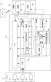
- FIG. 5 is a block diagram schematically showing the hierarchical structure of software in a vehicle (specifically, an in-vehicle device) and a server.
- FIG. 6 is a block diagram showing the functional configuration of the in-vehicle/outdoor communication unit shown in FIG. 3. As shown in FIG. FIG. FIG.
- FIG. 7 is a schematic diagram illustrating various delays in data transmission from the in-vehicle device to the server.
- FIG. 8 is a table showing parameters related to acquisition of moving image data.
- FIG. 9 is a flow chart showing processing related to uploading of moving image data executed by the vehicle interior/exterior communication unit.
- FIG. 10 is a flowchart showing a process of transmitting information used for uploading moving image data, which is executed by the in-vehicle/external linking unit, executed by the server.
- FIG. 11 is a diagram showing a state in which parameters are changed by time division.
- FIG. 12 is a flow chart showing processing related to uploading of moving image data executed by the vehicle interior/exterior communication unit according to the first modification.
- FIG. 13 is a block diagram showing functions of the vehicle interior/exterior communication unit according to the second modification.
- Patent Document 1 and Patent Document 2 consider the available communication band in the communication line (that is, wireless section), but the delay time of the in-vehicle device (for example, the delay time due to the load of the internal network, etc.) ) is not considered.
- the delay time of the in-vehicle device for example, the delay time due to the load of the internal network, etc.
- the present disclosure provides an in-vehicle device that can transmit data that can be effectively used by a service provided by the external device, taking into consideration the delay time and communication band.
- An object is to provide an apparatus, a control method and a computer program.
- An in-vehicle device is an in-vehicle device that is mounted in a vehicle and that transmits transmission data to a roadside device that is a device located outside the vehicle; An estimating unit that estimates the available bandwidth and end delay time that can be used in wireless communication with the roadside device, and the parameters that are used when generating the transmission data transmitted from the transmitting unit from the transmission target data. A determination unit that determines to satisfy the available bandwidth and the end delay time, and a generation unit that generates transmission data from the transmission target data using the parameters, and the end delay time is determined after the transmission target data is generated. It is the time until the transmitted data is delivered to the program that implements the service provided by the roadside device. As a result, when uploading data to an external device such as a roadside device, it is possible to transmit data that can be effectively used by the service provided by the external device, taking into consideration the delay time and communication bandwidth.
- the data to be transmitted may include moving image data obtained from a sensor mounted on a vehicle, and the parameters are the compression rate, resolution, frame rate, and bit rate of the transmission data. at least one of Thereby, the moving image data acquired from the sensor can be transmitted so as to satisfy the available bandwidth and the end delay time.
- the data to be transmitted may include moving image data acquired from each of a plurality of sensors mounted on the vehicle, and the determination unit includes a plurality of sensors according to the service provided by the roadside device, and the generation unit transmits moving image data obtained from each of the plurality of sensors according to the priority data may be generated.
- moving image data obtained from a plurality of sensors can be appropriately used by services provided by the roadside device.
- the priority may be a ratio of a communication band used for transmitting moving image data acquired from each of the plurality of sensors to the roadside device, and the determining unit , parameters may be determined for each moving image data so as to satisfy the communication bandwidth and end delay time determined from the available bandwidth and ratio. This makes it possible to efficiently determine an appropriate bit rate for transmitting moving image data obtained from each sensor to the roadside device.
- the available band is the communication speed estimated from the communication line quality of wireless communication and the on-vehicle device permitted in the provided wireless communication service. It may be a lower communication speed than the upper limit communication speed. This makes it possible to appropriately determine the parameters used when uploading data to an external device such as a roadside device.
- the generating unit may repeatedly determine the parameter with a predetermined period, and the predetermined period is a radio communication channel in radio communication. and at least one of the fluctuation period of the communication speed inside the vehicle. This makes it possible to appropriately determine the parameters used when uploading data to an external device such as a roadside device.
- the transmission target data can also be used by a function control device mounted on the vehicle. As a result, it is possible to avoid a situation in which the function control device cannot use the sensor data in order to transmit the sensor data to the roadside device.
- the transmitting unit may transmit the predetermined data before transmitting the transmission data
- the estimating unit may transmit the predetermined data when the predetermined data is transmitted.
- the predetermined data may include analysis results of sensor data obtained from sensors installed in the vehicle or data relating to the vehicle. This makes it possible to suppress data transmission for estimating the available bandwidth.
- the estimating unit determines the next usable Bandwidth may be estimated. As a result, unnecessary data transmission can be suppressed. This makes it possible to suppress data transmission for estimating the available bandwidth.
- the determination unit may determine parameters corresponding to each request, and the generation unit generates transmission data and the transmission unit transmits the transmission data to the roadside device for a predetermined period for each request. good too. As a result, data that can be effectively used by each service can be transmitted.
- the estimator may use the result of an AND operation of multiple requests to determine the parameters. Thereby, the data transmitted to the roadside device can be effectively used by any service.
- the transmission unit may transmit the transmission data to the roadside device in response to the occurrence of the event, and the event is the vehicle and/or the traffic conditions surrounding the vehicle. This makes it possible to reduce the amount of data transmitted within a certain period of time, compared to periodic transmission.
- the transmission unit may transmit the transmission data to the roadside device in response to the occurrence of an event, the event being the driving state of the vehicle and traffic conditions around the vehicle. It may relate to at least one of the states, and the ratio may change in response to the event occurring. As a result, it is possible to reduce the amount of data transmitted within a certain period of time compared to the case of periodic transmission, and to transmit appropriate sensor data according to the situation.
- the roadside device includes a communication unit that communicates with the in-vehicle device and observes the state of the service to be provided. and an infrastructure cooperation unit that specifies an allowable delay time that can be used for estimating the end delay time, and the communication unit transmits the allowable delay time to the in-vehicle device.
- the on-vehicle device that receives the allowable delay time can determine appropriate parameters to use when generating transmission data from the sensor data acquired from the own vehicle's sensors, and the data uploaded to the road-side device is provided by the road-side device. can be effectively used by services that
- a control method is a control method for an in-vehicle device mounted on a vehicle, comprising a transmission step of transmitting transmission data to a roadside device that is a device located outside the vehicle; , an estimation step of estimating an available bandwidth and an end delay time that the in-vehicle device can use in wireless communication with the roadside device; is determined so as to satisfy the available bandwidth and the end delay time, and a generation step of generating transmission data from the data to be transmitted using the parameters, and the end delay time is the time when the data to be transmitted is generated. to the time the transmitted data is passed to the computer program that implements the service provided by the roadside device.
- the in-vehicle device can transmit data that can be effectively used by the service provided by the external device, taking into consideration the delay time and communication band.
- a computer program includes a computer mounted on a vehicle, a transmission function of transmitting transmission data to a roadside device that is a device located outside the vehicle, and Estimation function for estimating available bandwidth and end delay time available in wireless communication, and parameters used when generating transmission data to be transmitted by the transmission function from data to be transmitted.
- a determination function that determines to satisfy the delay time and a generation function that generates transmission data from transmission target data using parameters are realized.
- the computer in-vehicle device
- the computer can transmit data that can be effectively used by the service provided by the external device, taking into consideration the delay time and communication bandwidth. .
- the cooperation system includes in-vehicle devices 100 and 110 mounted in vehicles 102 and 112, respectively, a base station 104, and a server .
- the base station 104 is connected to a network 108 such as the Internet.
- Base station 104 is a base station for wide area communication such as cellular communication.
- the base station 104 provides mobile communication services by, for example, LTE (Long Term Evolution), 4G (that is, fourth generation mobile communication system) lines, and 5G (that is, fifth generation mobile communication system) lines.
- LTE Long Term Evolution
- 4G that is, fourth generation mobile communication system
- 5G that is, fifth generation mobile communication system
- Each of in-vehicle device 100 and in-vehicle device 110 and server 106 can communicate with each other via base station 104 and network 108 .
- the base station 104 may provide wireless communication functions such as Wi-Fi and CV2X (Cellular-Vehicle to Everything).
- Each of vehicle 102 and vehicle 112 is equipped with a sensor such as an image sensor, and sensor data output from the sensor is acquired by in-vehicle device 100 and in-vehicle device 110 and transmitted to server 106 (hereinafter also referred to as upload). ) is done.
- the server 106 executes services such as provision of driving support information, remote monitoring and remote control, and uses sensor data received from the in-vehicle device 100 and the in-vehicle device 110 for the provided services.
- the server 106 may be a device arranged outside the vehicle 102 and the vehicle 112, or may be a roadside device fixedly installed on the road or its surroundings.
- FIG. 1 exemplarily shows one base station 104 and two vehicles 102 and 112 on which in-vehicle devices are mounted. But this is only an example. Usually, a plurality of base stations are provided, and in-vehicle devices are installed in three or more vehicles. There may be vehicles that are not equipped with an in-vehicle device. A vehicle without an in-vehicle device is a detection target of a sensor installed in a vehicle with an in-vehicle device.
- FIG. 2 shows a communication unit 120, a sensor 124, an automatic driving ECU 126, an ECU 128, and a bus 130 mounted on the vehicle 102.
- the vehicle 102 is equipped with a plurality of ECUs as devices (that is, function control devices) for controlling various functions of the vehicle.
- the automatic driving ECU 126 is one of the function control devices.
- a plurality of ECUs are mounted on the vehicle 102 in addition to the automatic driving ECU 126, and FIG. 2 shows an ECU 128 as a representative of them.
- the communication unit 120 performs wireless communication with devices outside the vehicle 102 via the base station 104 .
- the communication unit 120 includes an IC (Integrated Circuit) for performing modulation and multiplexing adopted in the wireless communication service provided by the base station 104, an antenna for transmitting and receiving radio waves of a predetermined frequency, and an RF Including circuits, etc.
- the communication unit 120 also has a function of communicating with GNSS (Global Navigation Satellite System) such as GPS (Global Positioning System).
- GNSS Global Navigation Satellite System
- GPS Global Positioning System
- the in-vehicle/outside cooperation unit 122 plays a role (for example, communication protocol conversion, etc.) that connects the communication function (ie, communication specification) with outside the vehicle and the communication function (ie, communication specification) inside the vehicle.
- the automatic driving ECU 126 can communicate with external devices via the vehicle interior/exterior communication unit 122 and the communication unit 120 .
- the vehicle interior/exterior cooperation unit 122 transfers the driving support information received from the outside via the communication unit 120 to the automatic driving ECU 126 .
- the bus 130 has a communication function inside the vehicle.
- Mutual communication that is, data exchange
- a bus 130 with respect to the in-vehicle/outdoor communication unit 122 , the sensor 124 , the automatic driving ECU 126 and the ECU 128 .
- Ethernet registered trademark
- CAN Controller Area Network
- the sensors 124 are mounted on the vehicle 102 and include sensors for acquiring information inside and outside the vehicle 102 .
- Sensors for acquiring information outside the vehicle include imaging devices (e.g., digital cameras (e.g., CCD cameras or CMOS cameras)), radars (e.g., millimeter wave radars, etc.), and laser sensors (e.g., LiDAR (Light Detection And Ranging)). etc.
- a sensor for obtaining information in the vehicle includes an imaging device.
- the sensor 124 acquires information within a detection range (for example, an imaging range in the case of a camera) and outputs it as sensor data.
- a digital camera outputs digital moving image data.
- a detection signal (that is, an analog or digital signal) of the sensor 124 is output to the bus 130 as digital data via an I/F unit (not shown), and is transmitted to the vehicle interior/exterior communication unit 122, the automatic driving ECU 126, and the like. be.
- the automatic driving ECU 126 controls the running of the vehicle 102.
- the autonomous driving ECU 126 acquires sensor data, analyzes it, grasps the situation around the vehicle, and controls mechanisms related to autonomous driving (for example, mechanisms such as the engine, transmission, steering, or brakes). do.
- the automatic driving ECU 126 uses driving support information (for example, dynamic information) acquired from the in-vehicle/outdoor communication unit 122 for automatic driving.
- vehicle interior/exterior communication unit 122 includes control unit 140 , memory 142 , I/F unit 144 and transmission data generation unit 146 .
- the control unit 140 includes a CPU (Central Processing Unit) and controls the memory 142 , the I/F unit 144 and the communication unit 120 . Control signals for this purpose are indicated by dashed arrows in FIG.
- the memory 142 is, for example, a rewritable non-volatile semiconductor memory, and stores computer programs (hereinafter simply referred to as programs) executed by the control unit 140 .
- Memory 142 provides a work area for programs executed by control unit 140 .
- the I/F section 144 is controlled by the control section 140 and interfaces with the sensor 124 (see FIG. 2). If the sensor 124 is a camera that outputs moving image data and it is possible to set a plurality of imaging conditions (for example, the resolution and frame rate of the output data), the control unit 140 controls the camera via the I/F unit 144. Set the imaging conditions. Under the control of the control unit 140 , the transmission data generation unit 146 generates transmission data from sensor data acquired from the sensor 124 and stored in the memory 142 . This sensor data is data to be transmitted to the server 106 (hereinafter also referred to as transmission target data). For example, if the sensor data is moving image data, the amount of data is large.
- transmission target data data to be transmitted to the server 106 (hereinafter also referred to as transmission target data). For example, if the sensor data is moving image data, the amount of data is large.
- the transmission data generator 146 converts the resolution and frame rate, and compresses the data so as not to constrict the communication band. If the transmission data generation unit 146 can generate transmission data from sensor data based on a plurality of conditions, the control unit 140 designates conditions (for example, resolution, frame rate, compression ratio, etc.) to the transmission data generation unit 146 . The transmission data generator 146 generates transmission data based on specified conditions. The generated transmission data is stored in memory 142 . The communication unit 120 is controlled by the control unit 140 to generate packet data from transmission data stored in the memory 142 and transmit the packet data. If the sensor data is moving image data, a predetermined amount of data sequentially acquired from the sensor 124 is buffered in the memory 142, and transmission data is generated from the buffered data and transmitted sequentially.
- the control unit 140 designates conditions (for example, resolution, frame rate, compression ratio, etc.) to the transmission data generation unit 146 .
- the transmission data generator 146 generates transmission data based on specified conditions.
- the generated transmission data is
- server 106 includes control unit 160 , memory 162 , communication unit 164 and bus 166 . Data transfer between units occurs via bus 166 .
- the control unit 160 includes a CPU, controls each unit, and implements various services.
- Communication unit 164 receives information (including sensor data, vehicle information, etc.) uploaded from in-vehicle device 100 and in-vehicle device 110 via base station 104 and network 108 .
- the memory 162 includes a rewritable non-volatile semiconductor memory and a mass storage device such as a HDD (Hard Disk Drive). The data received by communication unit 164 is transferred to memory 162 and stored therein.
- HDD Hard Disk Drive
- the data uploaded and stored in memory 162 is used by an application program (hereinafter simply referred to as an application) for implementing services.
- the communication unit 164 has a function of accessing the network 108 wirelessly or by wire. Under the control of control unit 160 , communication unit 164 transmits request data and the like to vehicle 102 and vehicle 112 from memory 162 .
- Server 106 includes an operation unit (not shown) such as a computer keyboard and mouse for the administrator or the like to input instructions to control unit 160 .
- the software of the cooperation system configured by vehicle 102 and server 106 is hierarchically configured.
- the hierarchical structure shown in FIG. 5 corresponds to, for example, the hierarchical structure of the OSI (Open Systems Interconnection) reference model.
- the vehicle 102 includes a plurality of ECUs as described above, and includes application programs (first-ECU application to second M-ECU application) for realizing the functions of each ECU in the upper layer.
- the upper layer applications are executed in parallel by a microcomputer or the like mounted on each ECU.
- a higher layer corresponds to, for example, the application layer of the OSI reference model.
- the vehicle 102 includes a communication stack responsible for communication with the outside (for example, below the session layer of the OSI reference model) in the lower layer, and a sublayer program that mediates between the upper layer program and the lower layer program in the middle layer.
- the middle layer corresponds, for example, to the presentation layer of the OSI reference model.
- the functions (or corresponding programs) of the in-vehicle/outdoor communication unit 122 of the in-vehicle device 100 are mainly positioned as sub-layer programs.
- the vehicle interior/exterior cooperation unit 122 controls the lower layer communication stack, and transmits sensor data such as moving image data to the server 106 as described above.
- the vehicle interior/exterior cooperation unit 122 controls the communication stack of the lower layer, and receives request data from the server 106 regarding transmission of sensor data such as moving image data, as will be described later.
- the vehicle interior/exterior cooperation unit 122 controls the lower layer communication stack, receives service data (for example, driving support information, etc.) transmitted from the server 106 as described above, and receives, for example, the automatic driving ECU 126 (see FIG.
- the function (or corresponding program) of the in-vehicle/outdoor cooperation unit 122 may include a part of a plurality of upper-layer applications. That is, the vehicle interior/exterior communication unit 122 may include functions as an ECU.
- the server 106 executes a plurality of services (including driving support, remote monitoring, remote control, etc.) as described above, and application programs (first service application to Nth service application) for realizing each service in the upper layer. )including.
- the server 106 includes a communication stack responsible for communication with the outside (for example, the in-vehicle device 100 of the vehicle 102, etc.) in the lower layer, and sub-layer programs that mediate the upper layer program and the lower layer program in the middle layer. include.
- the upper layer, the middle layer and the lower layer respectively correspond to the layers below the application layer, the presentation layer and the session layer of the OSI reference model, respectively.
- a program for realizing an infrastructure cooperation unit for communicating with the in-vehicle device 100 of the vehicle 102 to configure a cooperation system is mainly positioned as a sublayer program.
- the upper layer and middle layer programs are executed as multitasks by the control unit 160 (see FIG. 4).
- the infrastructure cooperation unit controls the communication stack of the lower layer, receives sensor data such as moving image data transmitted from the vehicle 102 as described above, and passes it to the program of the upper layer.
- the infrastructure linking unit observes the operation of the upper layer programs and acquires the conditions required by them (for example, request data such as allowable delay time).
- the server 106 controls the lower layer communication stack and transmits the requested data.
- the infrastructure cooperation unit controls the communication stack of the lower layer, and transmits service data (for example, driving support information, etc.) provided by the program of the upper layer to the in-vehicle device 100 of the vehicle 102 .
- In-vehicle/outdoor cooperation unit 122 includes control unit 140, memory 142, I/F unit 144, and transmission data generation unit 146, as shown in FIG.
- Control unit 140 includes estimation unit 220 , determination unit 222 and communication control unit 224 , and determination unit 222 includes parameter determination unit 226 and priority determination unit 228 .
- Transmission data generation section 146 includes frame rate conversion section 210 , resolution conversion section 212 and compression section 214 .
- the sensor 124 includes cameras 200 , 202 and 204 . These cameras are arranged on the vehicle 102 so that the camera 200 images the front of the vehicle 102 , the camera 202 images the rear of the vehicle 102 , and the camera 204 images the interior of the vehicle 102 .
- Camera 200, camera 202, and camera 204 may be cameras with the same specifications or cameras with different specifications.
- camera 200 that captures an image in front of vehicle 102 may have a higher resolution than either camera 202 or camera 204 .
- Camera 204 that captures images of the interior of the vehicle may also include a microphone that detects sound.
- the imaging conditions (including resolution, frame rate, etc.) of cameras 200 , 202 and 204 can be set by control section 140 via I/F section 144 .
- the frame rate conversion unit 210 reads the moving image data stored in the memory 142 and converts the moving image data so that the frame rate specified by the parameter determination unit 226 is obtained. For example, if the frame rate of the moving image data stored in the memory 142 (that is, the frame rate of the output data of the sensor 124) is an integral multiple of the frame rate specified by the parameter determination unit 226, the original moving image data By thinning out the converted moving image data can be generated. If there is no corresponding frame, the frame data of the converted moving image data can be generated by interpolation processing using a plurality of adjacent frame data in the original moving image data. The moving image data after conversion is stored in the memory 142 .
- the resolution conversion unit 212 reads the moving image data stored in the memory 142 and converts (that is, resizes) the moving image data so that the resolution is specified by the parameter determination unit 226 . Specifically, the pixel data of the converted frame is generated from the pixel data of each frame by interpolation processing or the like. The moving image data after resolution change is stored in the memory 142 .
- the processing of the frame rate conversion unit 210 and the resolution conversion unit 212 even if the resolution conversion unit 212 is executed for the result of executing the frame rate conversion unit 210, the result of executing the resolution conversion unit 212 is A frame rate converter 210 may be executed.
- the compression unit 214 reads the moving image data stored in the memory and compresses it to reduce the data size.
- the compression unit 214 compresses the moving image data so that the ratio of the data size after compression (per unit time, for example) to the data size of the original image (per unit time, for example) is the compression rate specified by the parameter determination unit 226. to compress.
- MPEG Motion Picture Experts Group
- MPEG2, MPEG4, etc. can be used as the compression method.
- compressed moving image data does not have a data structure in frame units. Therefore, when changing either the frame rate or the resolution, the corresponding processing of the frame rate conversion unit 210 and the resolution conversion unit 212 is executed.
- the subsequent moving image data is compressed by the compression unit 214 .
- the moving image data after compression is stored in the memory 142 .
- the estimation unit 220 estimates the UL communication speed and end delay time when data is uploaded from the in-vehicle device 100 to the server 106 .
- the UL communication speed means the available band for wireless communication, that is, the wireless communication speed.
- the end delay time means the time from when sensor data is output from the sensors mounted on the vehicle to when it is handed over to the service application being executed by the server.
- the estimator 220 calculates a transmission delay from the estimated end delay time. Transmission delay is the time it takes for data to be sent from the vehicle's communications unit until it is received by the server and passed to the application performing the service. That is, the transmission delay is the end delay time minus the delay time in the vehicle (for example, the time during which sensor data is transmitted and processed).
- Estimating section 220 outputs the estimated UL communication speed and the calculated delay time to parameter determining section 226 .
- the estimation unit 220 determines the maximum communication speed X (bps unit) at which stable communication is possible through observation.
- the maximum communication speed X (bps unit) represents the quality of the wireless communication line (that is, the communication line quality).
- the estimation unit 220 transmits a pilot signal (hereinafter referred to as a pilot packet) of a predetermined amount of data (more specifically, data size of payload) before uploading moving image data to the server 106 .
- the estimation unit 220 can calculate the communication speed by dividing the amount of data transmitted as a pilot packet by the transmission time of the pilot packet.
- the transmission time is calculated from the time stamp included in the packet notifying normal reception transmitted from the server 106, can be calculated by subtracting the timestamp of when the transmission of If the in-vehicle device 100 and the server 106 are asynchronous (that is, the timers of both show different times), the estimating unit 220 executes, for example, a PING command, and the RTT (Round-Trip Time) included in the response , the communication speed can be calculated. That is, since RTT represents round-trip time, 1/2 of it can be used as transmission time.
- an upper limit Y (in units of bps) of the upload communication speed that can be used by one communication terminal is set.
- the upper limit value Y (in units of bps) of the communication speed may be stored in advance in the memory 142, for example.
- data other than moving image data (for example, data related to vehicles) is also uploaded from the in-vehicle device 100 to the server 106 .
- the estimation unit 220 can determine the communication speed a by observing actual data transmission.
- the communication speed a may be pre-stored in the memory 142 .
- the real-time property required by the service (that is, service application) provided by the server 106 is different, and the delay time allowed for the moving image data received by the server 106 (hereinafter referred to as "allowable delay time") is accordingly different.
- the upper limit of the end delay time is limited.
- Time T1 is the time required for data (for example, moving image data) periodically transmitted (that is, output) from the camera 200 in units of frames to reach the memory 142 after being output from the camera 200 (hereinafter referred to as transmission cycle (or referred to as an acquisition period).
- a transmission cycle (that is, a capture cycle) is represented by the reciprocal of the frame rate (fps unit) of moving image data. Since the moving image data output from the camera 200 is composed of frames, and subsequent processing is performed on the frames, the delay time is the time until processing becomes possible (that is, the transmission cycle).
- Time T2 and time T3 are times required for image capture and processing by processing unit 250 .
- Image capture and processing unit 250 corresponds to frame rate conversion unit 210, resolution conversion unit 212, and compression unit 214 shown in FIG.
- the time T2 is the time required for the moving image data to be stored in the memory 142 and for the compression process to start (that is, the image capture delay). Note that the time T2 includes the time required for converting the moving image data, for example, the time required for converting the frame rate and resolution.
- the time T3 is the time required for the process of compressing the converted moving image data (that is, the compression time).
- Time T4 is the time required for transmission data (that is, moving image data after compression) to be read from memory 142, transmitted through in-vehicle device 100 to communication unit 120, and ready for transmission by communication unit 120 (that is, other processing time). ).
- Time T5 is the transmission delay described above.
- the transmission delay can be calculated by the following equation.
- the end delay time depends on the service of the server 106 as described above, so information for estimating the end delay time can be obtained from the server 106 .
- the estimation unit 220 estimates the end delay time used in Equation 1 from the allowable delay time transmitted from the server 106 . Since the allowable delay time is the upper limit of the end delay time, the estimator 220 can set the allowable delay time to be the end delay time of Equation 1, for example.
- a value slightly smaller than the allowable delay time may be set as the end delay time in Equation (1).
- the time T1 (that is, transmission period) is determined by the frame rate of the camera. Since time T2 to time T4 depends on the target data size (for example, resolution), if values corresponding to the data size (for example, measured values) are stored in advance in the memory 142 as a table, the estimating unit 220 uses the table , the time T2 to time T4 can be determined. Note that the time T3 (that is, the compression time) also depends on the compression ratio, so it is preferable that the table also considers the compression ratio.
- time T1 to T5 the ratio of each of the time T1 to the time T5 to the end delay time is the largest in the time T5 (that is, the transmission delay) (usually several hundred milliseconds to several seconds).
- the time T1 to T4 other than time T5 is considered to be less than 100 milliseconds. Therefore, time T1 to time T4 may be set to fixed values.
- the priority determining unit 228 determines the priority of multiple sensors (ie, camera 200, camera 202 and camera 204).
- the priority indicates which of the output data of a plurality of sensors is to be uploaded with priority.
- the priority determination unit 228 determines the ratio of the communication band (that is, communication speed) to be allocated for uploading the output data (that is, moving image data) of each sensor according to the running state of the vehicle 102 and the request from the server 106. do.
- the request from the server 106 is a request from the viewpoint that the server 106 uses the moving image data uploaded from the in-vehicle device 100 (that is, output data from the cameras 200, 202 and 204).
- Requests from server 106 depend, for example, on programs (ie, service applications) running on server 106 .
- programs ie, service applications
- a communication band is also allocated to the camera 204 that captures images of the interior of the vehicle.
- the priority may be designated from the outside of the in-vehicle device 100 (for example, an operation unit).
- the priority determination section 228 outputs the determined priority (that is, ratio) to the parameter determination section 226 .
- the parameter determining unit 226 determines the bit rate when uploading the sensor data (that is, moving image data) for each of the plurality of sensors (that is, camera 200, camera 202, and camera 204), and determines parameters related to moving image data. do. Parameters include frame rate, resolution and compression ratio.
- the parameter determination unit 226 outputs the determined parameters to the frame rate conversion unit 210, the resolution conversion unit 212 and the compression unit 214, and operates the frame rate conversion unit 210, the resolution conversion unit 212 and the compression unit 214 as described above. .
- transmission data is generated from moving image data, which is data to be transmitted.
- the parameters are parameters related to transmission data, not parameters related to moving image data output from cameras 200 , 202 , and 204 .
- the compression rate is the data size (for example, per unit time) of transmission data with respect to the data size (for example, per unit time) of moving image data output from cameras 200 , 202 and 204 .
- the moving image data after the transmission data is received by the server 106 and decompressed has the frame rate and resolution specified by the parameters.
- the parameter determination unit 226 assigns communication speeds (hereinafter referred to as allocation UL communication speed). That is, the parameter determining unit 226 proportionally distributes the UL communication speed input from the estimating unit according to the ratio input from the priority determining unit 228, and calculates each allocated UL communication speed. Subsequently, the parameter determining unit 226 multiplies each assigned UL communication speed by the transmission delay input from the estimating unit 220 to calculate (that is, determine) the bit rate at the time of transmission for each piece of moving image data.
- the bit rate is the upper limit of the amount of data that can be transmitted from the in-vehicle device 100 to the server 106 during transmission delay.
- the transmitted data ie moving image data
- the transmission data amount per unit time is larger than the determined bit rate, the data cannot be transmitted during the transmission delay, and the end delay time exceeds the allowable delay range of the service provided by the server 106. Therefore, the transmitted data (ie moving image data) is not effectively used by the services provided by the server 106 .
- the parameter determining unit 226 determines the parameters of the moving image data (that is, frame rate, resolution and compression ratio) so that the bit rate is equal to or less than the determined bit rate for each camera.
- the amount of moving image data per unit time includes the number of pixels in one frame (that is, the product of the number of vertical pixels and the number of horizontal pixels), the amount of data in one pixel (for example, 24 bits), the compression ratio, and the frame rate (that is, , number of frames per unit time). Normally, the amount of data for one pixel of a camera is fixed.
- the number of pixels in one frame is determined by the resolution, that is, the number of vertical and horizontal pixels. Therefore, a table as shown in FIG.
- the parameter determination unit 226 refers to the table to determine a combination of parameters whose data amount per unit time (that is, the moving image data amount shown in FIG. 8) is equal to or less than the bit rate and has the value closest to the bit rate. can. In FIG. 8, the ID is given a unique value for each parameter set. If there are a plurality of parameter sets with the same moving image data amount, one parameter set may be determined according to a predetermined criterion. For example, if real-time performance is required, a parameter set with a higher frame rate can be selected. A parameter set with a higher resolution or a lower compression rate can be selected when high accuracy in detecting an object is required.
- the resolution may have any number of pixels, but may have the number of pixels normally used.
- SD Standard Definition
- HD High Definition
- FHD Full High Definition
- 4K etc.
- SD is an image with 720 horizontal pixels and 480 vertical pixels
- HD is an image with 1280 horizontal pixels and 720 vertical pixels
- Full-HD is an image with 1920 horizontal pixels and 1080 vertical pixels
- 4K is an image with 3840 horizontal pixels and 1080 vertical pixels. It means an image of 2160 vertical pixels.
- some parameters may be fixed. For example, at least one of compression rate and frame rate may be fixed. In that case, by changing at least the resolution, the amount of data per unit time (that is, the amount of moving image data shown in FIG. 8) can be reduced below the required bit rate.
- the communication control unit 224 controls the receiving unit 242 and the transmitting unit 240 of the communication unit 120 to communicate with external devices. Specifically, the communication control unit 224 controls the receiving unit 242 and the transmitting unit 240 to transmit a pilot packet and receive a normally received packet from the server 106 as described above. Also, the communication control unit 224 may control the receiving unit 242 and the transmitting unit 240 to transmit PING packets and receive responses thereto, as described above. The communication control unit 224 controls the reception unit 242 to receive requests (for example, the allowable delay time and camera priority) transmitted from the server 106 and store them in the memory 142 .
- requests for example, the allowable delay time and camera priority
- the communication control unit 224 controls the transmission unit 240 of the communication unit 120 to transmit the transmission data generated by the frame rate conversion unit 210, the resolution conversion unit 212 and the compression unit 214 to the server 106.
- the communication control unit 224 may transmit data periodically at regular time intervals, or may transmit data in response to a trigger generated when some event occurs.
- the in-vehicle/outdoor cooperation unit 122 considers the available band for wireless communication (that is, the wireless communication speed) and the end delay time, and determines the priority of each of the plurality of sensors (camera 200, camera 202, and camera 204).
- parameters for generating transmission data from moving image data can be determined according to . That is, when uploading data to an external device such as a roadside device (for example, the server 106), it is possible to transmit data that can be effectively used by the service provided by the external device, taking into consideration the delay time and communication bandwidth.
- a roadside device for example, the server 106
- the present invention is not limited to this.
- it is not limited to transmission data generated from sensor data. It may be an analysis result of sensor data or the like.
- the in-vehicle/external linking unit 122 uses compression of transmission data as a parameter for generating transmission data from moving image data acquired from a sensor mounted on the vehicle. rate, resolution and frame rate. Therefore, moving image data acquired from the sensor can be transmitted so as to satisfy the available bandwidth and the end delay time.
- the bit rate at the time of transmission for each moving image data is calculated (that is, determined), and parameters (that is, compression rate, resolution and frame rate) has been described, but the present invention is not limited to this.
- the bit rate itself may be used as a parameter.
- the bit rate may be limited to a predetermined value or less in order to suppress transmission of unnecessary large-capacity data (for example, high-quality data). That is, an upper limit value is set for the bit rate, and if the bit rate determined as described above exceeds the preset upper limit value, the parameter determination unit 226 replaces the determined bit rate with the upper limit value.
- the parameters of moving image data may be determined as follows. Therefore, the parameter may be at least one of compression rate, resolution, frame rate and bit rate for the transmitted data.
- the in-vehicle/outdoor cooperation unit 122 determines the priority of the sensor that acquires the transmission target data used to generate the transmission data from among the plurality of sensors. Determined according to the service provided. Therefore, moving image data obtained from multiple sensors can be appropriately used by the services provided by the roadside device.
- the in-vehicle/exterior cooperation unit 122 determines the communication band used for transmitting the moving image data acquired from each of the plurality of sensors to the roadside device as the priority. Use ratios. Therefore, it is possible to efficiently determine an appropriate bit rate for transmitting moving image data acquired from each sensor to the roadside device.
- the in-vehicle/external cooperation unit 122 determines the communication speed estimated from the communication line quality of wireless communication and the upper limit allowed for the in-vehicle device in the provided wireless communication service.
- the available bandwidth that is, the UL communication speed
- the UL communication speed is determined from the smaller communication speed. Therefore, it is possible to appropriately determine the parameters used when uploading data to an external device such as a roadside device.
- Each functional block shown in FIG. 6 can be realized by hardware, software, or a mixture thereof.
- the processing executed by the frame rate conversion unit 210, the resolution conversion unit 212, the compression unit 214, the estimation unit 220, the parameter determination unit 226, and the priority determination unit 228 are executed.
- dedicated hardware for example, a circuit board or an ASIC (Application Specific Integrated Circuit), etc.
- the control unit 140 may execute a predetermined program (see FIG. 9), as will be described later.
- FIG. 9 the operation of the vehicle interior/exterior communication unit 122 will be described with reference to the functions shown in FIG.
- the processing shown in FIG. 9 is implemented by control unit 140 shown in FIG. 3 reading out a predetermined program from memory 142 and executing the program.
- the processing shown in FIG. 9 is started when the in-vehicle device 100 is instructed to upload sensor data (that is, moving image data).
- An instruction to upload can be made by turning on the power of the in-vehicle device 100 or by giving an explicit instruction to the in-vehicle device 100 via the operation unit.
- the upper limit value Y (bps unit) of the upload communication speed that can be used by one communication terminal is stored in the memory 142 . Further, it is assumed that predetermined values are stored in the memory 142 as fixed values from time T1 to time T4. Assume that the memory 142 also stores a table for determining parameters (ie, frame rate, resolution and compression ratio) as shown in FIG.
- control unit 140 controls the communication unit 120 and determines whether or not a service request has been received from the server 106 . If so, control proceeds to step 302 . Otherwise control passes to step 314 .
- a service request is sent from the server 106 and is a request (eg, acceptable delay time and priority) of the application program that the server 106 is executing.
- control unit 140 stores the service request received at step 302 in the memory 142 . Control then passes to step 304 .
- control unit 140 estimates the UL communication speed Z. This corresponds to the function of the estimation unit 220 described above.
- Control unit 140 measures maximum communication speed X (in units of bps), reads upper limit value Y (in units of bps) of the upload communication speed from memory 142, and determines the communication speed assigned to transmission of data other than moving image data.
- the control unit 140 estimates the end delay time and calculates the transmission delay as described above. This corresponds to the function of the estimation unit 220 described above.
- the control unit 140 reads the service request (that is, the allowable delay time) and the times T1 to T4 from the memory 142, estimates the end delay time from the allowable delay time, and subtracts the sum of the times T1 to T4 from the end delay time. to calculate the transmission delay. Control then passes to step 308 .
- the control unit 140 determines the UL communication speed (that is, the assigned UL communication speed) for each sensor. This corresponds to the function of the parameter determining section 226 described above.
- the control unit 140 reads the service request (that is, priority) from the memory 142, proportionally distributes the UL communication speed determined in step 304 according to the priority, and determines the allocated UL communication speed.
- the priority is, for example, the ratio of the communication band to be allocated, and as described above, the server 106 transmits, for example, the ratios for the front camera, rear camera, and in-vehicle camera. Control then passes to step 310 .
- control unit 140 uses the allocated UL communication speed determined at step 310 and the transmission delay estimated at step 306 to determine the bit rate for each sensor. This corresponds to the function of the parameter determining section 226 described above.
- the control unit 140 multiplies the assigned UL communication speed by the transmission delay to determine the bit rate for transmitting the moving image data acquired by each sensor. Control then passes to step 312 .
- control unit 140 uses each bit rate determined at step 310 to refer to the table stored in the memory 142 and determines parameters for each sensor. This corresponds to the function of the parameter determining section 226 described above. Control then passes to step 314 .
- the determined parameters are stored in memory 142 . For example, in the case of a table as shown in FIG. 8, control unit 140 stores in memory 142 information specifying the ID of the determined parameter set.
- control unit 140 determines whether or not to transmit (ie, upload) the sensor data (that is, moving image data) acquired from each sensor to the server 106 . If so, control passes to step 316 . Otherwise control passes to step 318 . For example, if it is set to periodically upload at a certain time interval ⁇ T, the control unit 140 acquires the current time, and if the time ⁇ T has passed since the previous upload, the transmission If it does not pass, it is determined not to transmit. The control unit 140 acquires the current time from the timer inside the in-vehicle device 100 .
- control unit 140 reads the parameters determined at step 312 from the memory 142, and according to the parameters, generates transmission data from sensor data (that is, moving image data). Control unit 140 controls communication unit 120 and transmits the generated transmission data to server 106 . Control then passes to step 318 . Note that if the control unit 140 has never received a service request, the control unit 140 generates transmission data using default parameters. Default parameters may be stored in memory 142 in advance.
- control unit 140 determines whether or not an end instruction has been received. If it is determined that an end instruction has been received, this program ends. Otherwise, control returns to 300 and the process described above is repeated.
- the end instruction is made, for example, by turning off a power supply installed in the vehicle 102 .
- the in-vehicle/outdoor cooperation unit 122 considers the available band for wireless communication (that is, the wireless communication speed) and the end delay time, and converts the transmission data from the moving image data according to the priority of each of the plurality of sensors. can determine the parameters for generating Transmission data is generated using the determined parameters and uploaded to the server 106 so that the server 106 can make better use of the received sensor data by the services it provides.
- control unit 160 determines whether or not to start a service that uses sensor data (that is, moving image data) uploaded from the in-vehicle device.
- the service is started, for example, according to a predetermined schedule, or by an administrator's instruction by operating the operation unit of the server 106 . If so, control passes to step 402 . Otherwise control passes to step 404 .
- Services include, for example, provision of driving support information, remote monitoring and remote control.
- control unit 160 activates the applicable application. Control then passes to step 404 .
- the control unit 160 determines whether to transmit a service request.
- the service request includes the delay time required for the running service to effectively use the uploaded data (that is, the allowable delay time), the priority of the in-vehicle sensor (eg, camera), and the like. If so, control passes to step 406 . Otherwise control passes to step 408 . For example, if any upload data is available to the service application, it is determined not to send the service request.
- control unit 160 transmits a service request.
- the transmission is performed, for example, by broadcasting.
- Control then passes to step 408 .
- the transmitted request is used by the vehicle-mounted device that receives it to determine the parameters as described above.
- control unit 160 determines whether sensor data (for example, moving image data) has been received. If so, control passes to step 410 . Otherwise, control transfers to step 412 .
- sensor data for example, moving image data
- control unit 160 passes the sensor data received at step 408 to the running service application. Control then passes to step 412 .
- the control unit 160 notifies the service application of access information (eg, memory address, etc.) to the sensor data stored in the memory 162 .
- the service application accesses the memory 162 and acquires sensor data. If the received sensor data satisfies the service request sent from the server 106, the service application can effectively use the sensor data.
- control unit 160 determines whether or not to terminate the service being executed.
- the service is terminated, for example, according to a predetermined schedule or by the administrator operating the operation unit of the server 106 to give an instruction. If so, control passes to step 414 . Otherwise control passes to step 416 .
- control unit 160 terminates the corresponding service application. Control then passes to step 416 .
- control unit 160 determines whether or not an end instruction has been received. If it is determined that an end instruction has been received, this program ends. Otherwise, control returns to step 400 and the above process is repeated.
- An instruction to end is made by, for example, the operation unit of the server 106 being operated by an administrator or the like.
- the server 106 sends a service request (for example, an allowable delay time and priority, etc.) can be sent.
- a service request for example, an allowable delay time and priority, etc.
- the in-vehicle device that receives the service request can determine the appropriate parameters to use when generating transmission data from the sensor data obtained from the own vehicle's sensors, and the data uploaded to the server 106 is effective according to the service provided by the server 106. can be used for
- the in-vehicle/exterior linking unit 122 and the server 106 operate in cooperation, so that the in-vehicle/outside linking unit 122 considers the available band for wireless communication (that is, the wireless communication speed) and the end delay time.
- parameters for generating transmission data from moving image data can be determined according to the priority of each of the plurality of sensors. That is, when uploading data to an external device such as a roadside device (for example, the server 106), it is possible to transmit data that can be effectively used by the service provided by the external device, taking into consideration the delay time and communication bandwidth.
- the control section 140 may determine whether or not a trigger requesting an upload has occurred. For example, when a specific traffic situation occurs (for example, an accident occurs), or when the vehicle 102 enters a specific running state (for example, entering an intersection), the automatic driving ECU 126 or the ECU 128 (see FIG. 2) ) can be made to output a trigger.
- a specific traffic situation for example, an accident occurs
- a specific running state for example, entering an intersection
- the automatic driving ECU 126 or ECU 128 analyzes moving image data acquired from the camera 200 and the camera 202 that capture images of the outside of the vehicle, and detects objects requiring attention on road traffic (for example, traffic signs, pedestrians, red lights, etc.). can be detected.
- road traffic for example, traffic signs, pedestrians, red lights, etc.
- a trigger may be output when any one or a combination of these is detected. In the case of event transmission, the amount of data transmitted within a certain period can be reduced more than in the case of periodic transmission.
- the ratio of the communication band allocated to the in-vehicle cameras 200, 202, and 204 for transmission may be changed. For example, when entering an intersection, the camera 200 that images the front is given priority (that is, a higher ratio is assigned), and when leaving the intersection, the camera 204 that images the rear is given priority (that is, a higher ratio is assigned). good too. Accordingly, appropriate sensor data can be transmitted depending on the situation.
- the in-vehicle/external linking unit 122 selects the moving image data to be uploaded.
- the parameters for generation can be appropriately determined. Therefore, the uploaded data can be effectively used by multiple applications.
- the requirements eg, acceptable delay time, etc.
- some service applications will not be able to effectively utilize the received data if the same parameters are used.
- the internal/external linking unit 122 classifies the application programs according to the degree of approximation of the requests, determines different parameters for each request, and time-divides them as shown in FIG. Then, upload to the service application corresponding to each request. That is, the in-vehicle/outdoor cooperation unit 122 generates and uploads transmission data from the moving image data using the first parameter set during the period ⁇ T1. The uploaded data is passed to the corresponding service application. During a period ⁇ T2 following the period ⁇ T1, the vehicle interior/exterior cooperation unit 122 generates and uploads transmission data from the moving image data using the second parameter set. The uploaded data is passed to the corresponding service application.
- a period ⁇ T1 in which the first parameter set is used and a period T2 in which the second parameter set is used are repeated.
- the length of the period ⁇ T1 and the period ⁇ T2 may be the same or different. Even if there are three or more types of allowable delay times (that is, three or more parameter sets), the vehicle interior/exterior communication unit 122 may similarly increase the number of divisions and sequentially use different parameter sets by time division. This makes it possible to transmit data that can be effectively used by each service application.
- the in-vehicle/exterior linking unit 122 may perform an AND operation on a plurality of requests, determine parameters using the result, and generate transmission data from moving image data using the parameters. . If the request is an allowable delay time, the smallest allowable delay time is determined by the AND operation of a plurality of requests. decide.
- the uploaded data is passed to all service applications running on server 106 . The uploaded data meets the most stringent requirements and can be effectively used by any service application.
- a port number is used to identify a service application that delivers uploaded sensor data that satisfies a predetermined request from among multiple service applications running on the server 106 . That is, when a service request is transmitted from the server 106, the port number of the corresponding service application is added and transmitted, and when the in-vehicle device that receives the service request uploads the sensor data, the port number is added and uploaded. . This allows the server 106 to identify the service application corresponding to the port number added to the received sensor data.
- the control unit 140 may store the port number added to the received service request in the memory 142 in association with the service request (see step 302 in FIG. 9). The control unit 140 can specify the corresponding port number when transmitting the transmission data generated using the parameters determined according to the service request, and can add the specified port number to the transmission data (step in FIG. 9). 316).
- transmission data is generated by the frame rate conversion unit 210 and the resolution conversion unit 212 using the determined parameters (that is, frame rate and resolution).
- Camera 200, camera 202, and camera 204 may have the function of changing the frame rate and resolution to output moving image data.
- the control unit 140 may instruct the camera 200, the camera 202, and the camera 204 via the I/F unit 144 to output moving image data based on the determined parameters (ie frame rate and resolution). .
- the in-vehicle/outdoor cooperation unit 122 does not have to include the frame rate conversion unit 210 and the resolution conversion unit 212 .
- the frame rate used by the frame rate conversion unit 210 and the frame rate used by the frame rate conversion unit 210 and The resolution used by the resolution converter 212 may be determined.
- the server 106 transmits a service request (e.g., allowable delay time, priority, etc.), and using it to determine parameters used to generate transmission data to be uploaded by the in-vehicle device.
- a service request e.g., allowable delay time, priority, etc.
- the in-vehicle device knows the content of the service provided by the server 106, the in-vehicle device independently determines (i.e., guesses) the service request (for example, the allowable delay time, priority, etc.) and parameters may be determined in
- FIG. 12 shows a flowchart in which step 340 is added to the flowchart of FIG.
- the processing contents of the steps with the same reference numerals as in the flowchart of FIG. 9 are the same as those of FIG.
- an in-vehicle device that executes the flowchart shown in FIG. 12 is configured in the same manner as in FIGS.
- the processing shown in FIG. 12 is implemented by control unit 140 shown in FIG. 3 reading out a predetermined program from memory 142 and executing the program. Therefore, description will be made mainly on the points of difference without repeating redundant description.
- control unit 140 determines whether or not a service request has been received from the server 106. If it is determined that a service request has been received, control proceeds to step 302. This determines the parameters (ie frame rate, resolution and compression ratio) as described above. On the other hand, if it is determined that it has not been received, control proceeds to step 340 .
- control unit 140 determines whether or not to update the parameters. If so, control passes to step 304 where the parameters (ie frame rate, resolution and compression ratio) are determined as described above. Otherwise control passes to step 314 .
- the parameters ie frame rate, resolution and compression ratio
- Parameters may be updated at regular intervals or according to a predetermined schedule. Since the communication speed may change with fluctuations in the wireless communication channel, it is preferable to set the update period in consideration of the fluctuation period of the wireless communication channel when the parameter is updated at regular intervals.
- the fluctuation period of a wireless communication channel is the time (eg, average value) that the channel is maintained. That is, the parameter update period is set to a value shorter than the fluctuation period of the wireless communication channel. If the parameter update period is longer than the fluctuation period of the wireless communication channel, the amount of moving image data that exceeds the available bandwidth may be transmitted during upload, exceeding the allowable delay time. Also, packet errors and packet losses may occur. This allows you to properly determine the parameters used when uploading data.
- the wireless section which is the external environment of the vehicle, often becomes a bottleneck in the available bandwidth. T4) may fluctuate. Therefore, it is also preferable to set the parameter update cycle to a time sufficiently short with respect to the vehicle state fluctuation cycle.
- the fluctuation cycle of the vehicle state is, for example, the fluctuation cycle of the in-vehicle communication speed due to fluctuations in the load factor and processing capacity of the in-vehicle network and ECU.
- the fluctuation period of the in-vehicle communication speed is the time (for example, average value) during which the in-vehicle communication speed is maintained within a certain range. Sufficiently short means, for example, 1/10 or less. This allows you to properly determine the parameters used when uploading data.
- the in-vehicle device includes a communication unit 120 and an in-vehicle/exterior cooperation unit 122, like the in-vehicle device 100 shown in FIG.
- Communication unit 120 and in-vehicle/exterior communication unit 122 are configured in the same manner as in FIG. 3 and have the same functions as in FIG. Bus 130 (see FIG. 3) is not shown in FIG.
- one camera 200 is shown as a sensor in FIG. 13 for the sake of convenience, the vehicle has a plurality of cameras as in FIG.
- FIG. 13 shows an automatic driving ECU 126 as an ECU that uses moving image data output from the camera 200 .
- the ECU that uses the moving image data output from the camera 200 may be an ECU other than the automatic driving ECU 126 .
- the automatic driving ECU 126 acquires moving image data by controlling the camera 200 as indicated by the dotted arrow, temporarily stores it in the memory inside the automatic driving ECU 126, and uses the analysis results for automatic driving.
- the frame rate and resolution of moving image data output from the camera 200 to the automatic driving ECU 126 are suitable for automatic driving.
- In-vehicle/exterior linking unit 122 copies the data output from camera 200 and stores it in memory 142 (see FIG. 3). Thereby, the moving image data output from the camera 200 is stored in the memory 142 .
- the in-vehicle/exterior cooperation unit 122 uses the determined parameters to convert the moving image data stored in the memory 142 by the frame rate conversion unit 210 and the resolution conversion unit 212 (that is, the frame rate and the resolution conversion unit 212). resolution) and compressed by the compression unit 214 to generate transmission data.
- the frame rate conversion unit 210 and the resolution conversion unit 212 that is, the frame rate and the resolution conversion unit 2112. resolution
- the compression unit 214 it is possible to avoid a situation in which the automatic driving ECU 126 cannot use the sensor data in order to transmit the sensor data to the server 106 .
- the automatic driving ECU 126 temporarily stores the moving image data used in automatic driving in the memory 142 of the in-vehicle/outdoor communication unit 122, and then reads the data from the memory 142 (see the dashed arrow in FIG. 13). , and may be analyzed.
- the automatic driving ECU 126 instructs the control unit 140 (see FIG. 3) of the vehicle interior/exterior cooperation unit 122 to capture the output data of the camera 200, and upon receiving the instruction, the control unit 140 causes the I/F unit 144 ( 3), the output data of the camera 200 may be stored in the memory 142.
- FIG. the automatic driving ECU 126 can use the analysis result for automatic driving, and the in-vehicle/outdoor communication unit 122 can generate transmission data using the determined parameters.
- the case of transmitting a pilot packet and estimating the UL communication speed has been described, but it is not limited to this.
- it may be scheduled to transmit data other than moving image data (for example, analysis results of sensor data, vehicle data, etc.) before transmitting moving image data.
- Data other than moving image data transmitted at this time can be substituted for the pilot packet.
- data other than moving image data it is preferable to use data that has a data size comparable to that of a pilot packet and that has a high degree of freedom in transmission timing. This makes it possible to suppress the transmission of pilot packets for estimating the available bandwidth.
- the UL communication speed may be estimated by observing the transmission data amount and transmission time when the data to be transmitted (for example, video data, etc.) was transmitted last time. Also, the UL communication speed may be calculated using an estimation model (for example, based on deep learning or mathematical techniques) that estimates future communication quality from current and past communication quality data. This makes it possible to suppress the transmission of pilot packets for estimating the available bandwidth.
- an estimation model for example, based on deep learning or mathematical techniques
- Each process (each function) of the above-described embodiment may be realized by a processing circuit (circuitry) including one or more processors.
- the processing circuit may be configured by an integrated circuit or the like in which one or more memories, various analog circuits, and various digital circuits are combined in addition to the one or more processors.
- the one or more memories store programs (instructions) that cause the one or more processors to execute the processes.
- the one or more processors may execute the processes according to the program read from the one or more memories, or execute the processes according to a logic circuit designed in advance to execute the processes. may be executed.
- the processor may be a CPU, GPU (Graphics Processing Unit), DSP (Digital Signal Processor), FPGA (Field Programmable Gate Array), ASIC, or any other suitable processor for computer control.
- a recording medium recording a program for causing a computer to execute the processing of the in-vehicle device 100 (specifically, the processing executed by the in-vehicle/external communication unit 122 (for example, the processing shown in FIGS. 9 and 12))
- the recording medium is, for example, an optical disc (DVD (Digital Versatile Disc), etc.), a removable semiconductor memory (USB (Universal Serial Bus) memory, etc.).
- the computer program can be transmitted via a communication line, but the recording medium is non-temporary.
- the computer can upload the data to the external device such as the roadside device, as described above. It is possible to transmit data that can be effectively used by the service provided by the external device, taking into consideration the delay time and communication band.
- the computer-readable non-transitory recording medium is computer on board the vehicle, a transmission function for transmitting transmission data to a roadside device, which is a device located outside the vehicle; an estimation function for estimating an available bandwidth and an end delay time that the computer can use in wireless communication with the roadside device; a determination function that determines parameters used when generating the transmission data transmitted by the transmission function from transmission target data so as to satisfy the available bandwidth and the end delay time; realizing a generation function that generates the transmission data from the transmission target data using the parameters;
- the end delay time stores the computer program, which is the time from when the data to be transmitted is generated to when the transmission data is passed to the computer program that implements the service provided by the roadside device.
Landscapes
- Engineering & Computer Science (AREA)
- Signal Processing (AREA)
- Multimedia (AREA)
- Computer Networks & Wireless Communication (AREA)
- Databases & Information Systems (AREA)
- Traffic Control Systems (AREA)
Abstract
車載装置は、車両に搭載される車載装置であって、車両の外部に位置する装置である路側装置に送信データを送信する送信部と、車載装置が路側装置との無線通信において利用可能な利用可能帯域とエンド遅延時間とを推定する推定部と、送信部から送信される送信データを送信対象データから生成する際に使用されるパラメータを、利用可能帯域およびエンド遅延時間を満たすように決定する決定部と、パラメータを用いて、送信対象データから送信データを生成する生成部とを含み、エンド遅延時間は、送信対象データが生成されてから、送信データが、路側装置により提供されるサービスを実現するコンピュータプログラムに渡されるまでの時間である。
Description
本開示は、車載装置、路側装置、制御方法およびコンピュータプログラムに関する。本出願は、2021年10月29日出願の日本出願第2021-177405号に基づく優先権を主張し、前記日本出願に記載された全ての記載内容を援用するものである。
自動車および自動二輪車等(以下、車両という)に搭載された車載装置とサーバ等の外部装置との連携システムが提案されている。例えば、車載装置から外部装置に、無線通信を介してデータをアップロードし、外部装置は受信したデータを、提供している種々のサービスにおいて利用する。外部装置が提供するサービスとして、車両の運転者を支援する情報を提供するサービスがある。
近年の車両には、種々の電子機器が装備され、それらを制御するECU(Electronic Control Unit)が搭載されている。例えば、自動運転可能な車両には、自動運転用ECUが搭載されている。自動運転用ECUは、適宜外部と通信し、必要な情報(例えば、道路交通情報および動的な運転支援情報を含む)を取得し、取得した情報を用いて自車両の走行を制御する。その他の車載ECUとして、エンジン制御ECU、ストップスタート制御ECU、トランスミッション制御ECU、エアバッグ制御ECU、パワーステアリング制御ECUおよびハイブリッド制御ECU等がある。自動運転可能な車両に関しては、外部装置は、遠隔監視および遠隔制御等のサービスを提供する。
下記特許文献1には、車両等の移動体に搭載され、移動体において取得されたセンサ情報を、センサ(例えばカメラ等)の重要度に基づいて遠隔装置等へ送信できる通信装置が開示されている。この通信装置は、自車両の移動状態および周辺状態に基づいて各センサの優先度を決定し、優先度の高いセンサにより検出された情報を、優先度の低いセンサにより検出された情報よりも高品質に送信できるように通信制御を行う。
下記特許文献2には、携帯電話網経由による車両遠隔監視および制御において、口スおよび遅延を抑制しつつ、遠隔運転に適した高品質な映像を送信可能な送信方法が開示されている。この送信方法は、車両に搭載された複数台の力メラが撮影した画像を、ネットワークを介して送信する送信方法であって、ネットワークにおいて使用可能な帯域である使用可能帯域を推定し、使用可能帯域とカメラ毎の重要度とに応じて、カメラ毎に帯域を割当てる。
本開示のある局面に係る車載装置は、車両に搭載される車載装置であって、車両の外部に位置する装置である路側装置に送信データを送信する送信部と、車載装置が路側装置との無線通信において利用可能な利用可能帯域とエンド遅延時間とを推定する推定部と、送信部から送信される送信データを送信対象データから生成する際に使用されるパラメータを、利用可能帯域およびエンド遅延時間を満たすように決定する決定部と、パラメータを用いて、送信対象データから送信データを生成する生成部とを含み、エンド遅延時間は、送信対象データが生成されてから、送信データが、路側装置により提供されるサービスを実現するコンピュータプログラムに渡されるまでの時間である。
[本開示が解決しようとする課題]
車載装置から外部装置(例えば路側装置等)にアップロードしたデータが、外部装置が提供するサービスを実現するためのアプリケーションにより有効に利用されるには、遅延時間が考慮されることが重要である。特に、リアルタイム性が要求される遠隔制御および遠隔監視等のサービスにおいては、遅延時間を考慮することが不可欠である。遅延時間には、通信による遅延時間に限らず、エンドシステムとしての車両内における遅延時間がある。しかし、特許文献1および特許文献2においては、遅延時間が十分に考慮されていない。即ち、特許文献1および特許文献2のいずれにおいても、通信回線(即ち無線区間)における利用可能な通信帯域は考慮されているが、車載装置の遅延時間(例えば、内部ネットワークの負荷等による遅延時間)が考慮されていない問題がある。特に、外部装置において実行される複数サービスおよびバックトラフィックとの共存時に問題が発生し得る問題がある。
車載装置から外部装置(例えば路側装置等)にアップロードしたデータが、外部装置が提供するサービスを実現するためのアプリケーションにより有効に利用されるには、遅延時間が考慮されることが重要である。特に、リアルタイム性が要求される遠隔制御および遠隔監視等のサービスにおいては、遅延時間を考慮することが不可欠である。遅延時間には、通信による遅延時間に限らず、エンドシステムとしての車両内における遅延時間がある。しかし、特許文献1および特許文献2においては、遅延時間が十分に考慮されていない。即ち、特許文献1および特許文献2のいずれにおいても、通信回線(即ち無線区間)における利用可能な通信帯域は考慮されているが、車載装置の遅延時間(例えば、内部ネットワークの負荷等による遅延時間)が考慮されていない問題がある。特に、外部装置において実行される複数サービスおよびバックトラフィックとの共存時に問題が発生し得る問題がある。
したがって、本開示は、路側装置等の外部装置にデータをアップロードする際に、遅延時間および通信帯域を考慮して、外部装置が提供するサービスにより有効に利用され得るデータを送信できる車載装置、路側装置、制御方法およびコンピュータプログラムを提供することを目的とする。
[発明の効果]
本開示によれば、路側装置等の外部装置にデータをアップロードする際に、遅延時間および通信帯域を考慮して、外部装置が提供するサービスにより有効に利用され得るデータを送信できる車載装置、路側装置、制御方法およびコンピュータプログラムを提供できる。
本開示によれば、路側装置等の外部装置にデータをアップロードする際に、遅延時間および通信帯域を考慮して、外部装置が提供するサービスにより有効に利用され得るデータを送信できる車載装置、路側装置、制御方法およびコンピュータプログラムを提供できる。
[本開示の実施形態の説明]
本開示の実施形態の内容を列記して説明する。以下に記載する実施形態の少なくとも一部を任意に組合せてもよい。
本開示の実施形態の内容を列記して説明する。以下に記載する実施形態の少なくとも一部を任意に組合せてもよい。
(1)本開示の第1の局面に係る車載装置は、車両に搭載される車載装置であって、車両の外部に位置する装置である路側装置に送信データを送信する送信部と、車載装置が路側装置との無線通信において利用可能な利用可能帯域とエンド遅延時間とを推定する推定部と、送信部から送信される送信データを送信対象データから生成する際に使用されるパラメータを、利用可能帯域およびエンド遅延時間を満たすように決定する決定部と、パラメータを用いて、送信対象データから送信データを生成する生成部とを含み、エンド遅延時間は、送信対象データが生成されてから、送信データが、路側装置により提供されるサービスを実現するプログラムに渡されるまでの時間である。これにより、路側装置等の外部装置にデータをアップロードする際に、遅延時間および通信帯域を考慮して、外部装置が提供するサービスにより有効に利用され得るデータを送信できる。
(2)上記の(1)において、送信対象データは、車両に搭載されたセンサから取得された動画像データを含むことができ、パラメータは、送信データに関する圧縮率、解像度、フレームレートおよびビットレートのうちの少なくとも1つを含むことができる。これにより、センサから取得された動画像データを、利用可能帯域およびエンド遅延時間を満たすように送信できる。
(3)上記の(1)または(2)において、送信対象データは、車両に搭載された複数のセンサの各々から取得された動画像データを含んでいてもよく、決定部は、複数のセンサの各々の優先度を、路側装置が提供するサービスに応じて決定する優先度決定部を含んでいてもよく、生成部は、複数のセンサの各々から取得された動画像データから優先度に従って送信データを生成してもよい。これにより、複数のセンサから取得された動画像データは、路側装置が提供するサービスにより適切に利用され得る。
(4)上記の(3)において、優先度は、複数のセンサの各々から取得された動画像データを路側装置に送信するために使用される通信帯域の比率であってもよく、決定部は、利用可能帯域および比率から決定される通信帯域およびエンド遅延時間を満たすように、動画像データ毎にパラメータを決定してもよい。これにより、各センサから取得された動画像データを、路側装置に送信するときの適切なビットレートを効率的に決定できる。
(5)上記の(1)から(4)のいずれか1つにおいて、利用可能帯域は、無線通信の通信回線品質から推定される通信速度と、提供される無線通信サービスにおいて車載装置に許可される上限の通信速度とのうち、より小さい通信速度であってもよい。これにより、路側装置等の外部装置にデータをアップロードする際に使用されるパラメータを適切に決定できる。
(6)上記の(1)から(5)のいずれか1つにおいて、生成部は、所定の周期を以ってパラメータを繰返し決定してもよく、所定の周期は、無線通信における無線通信チャネルの変動周期、および、車両の内部における通信速度の変動周期の少なくとも一方の変動周期よりも短くてもよい。これにより、路側装置等の外部装置にデータをアップロードする際に使用されるパラメータを適切に決定できる。
(7)上記の(1)から(6)のいずれか1つにおいて、送信対象データは、車両に搭載されている機能制御装置によっても利用されることができる。これにより、路側装置にセンサデータを送信するために、機能制御装置がセンサデータを利用できない状況が生じることを回避できる。
(8)上記の(1)から(7)のいずれか1つにおいて、送信部は、送信データを送信する前に所定データを送信してもよく、推定部は、所定データが送信された際の通信速度に基づいて、利用可能帯域を推定してもよく、所定データは、車両に搭載されているセンサから取得されたセンサデータの解析結果または車両に関するデータを含んでいてもよい。これにより、利用可能帯域を推定するためのデータ送信を抑制できる。
(9)上記の(1)から(7)のいずれか1つにおいて、推定部は、送信部により送信データが送信された際の通信速度に基づいて、決定部により次に利用される利用可能帯域を推定してもよい。これにより、無駄なデータの送信を抑制できる。これにより、利用可能帯域を推定するためのデータ送信を抑制できる。
(10)上記の(1)から(9)のいずれか1つにおいて、路側装置により、エンド遅延時間の推定に用いられ得る要求が相互に異なる複数のサービスが並行して提供されている状態において、決定部は、要求毎に対応するパラメータを決定してもよく、要求毎に所定の期間、生成部による送信データの生成、および、送信部による送信データの路側装置への送信が行われてもよい。これにより、各サービスによって有効に利用され得るデータを送信できる。
(11)上記の(1)から(9)のいずれか1つにおいて、路側装置により、エンド遅延時間の推定に用いられ得る要求が相互に異なる複数のサービスが並行して提供されている状態において、推定部は、複数の要求のAND演算の結果を用いてパラメータを決定してもよい。これにより、路側装置に送信されたデータは、いずれのサービスによっても有効に利用され得る。
(12)上記の(1)から(5)のいずれか1つにおいて、送信部は、イベントが発生したことを受けて、路側装置への送信データの送信を行ってもよく、イベントは、車両の走行状態および車両の周囲の交通状態の少なくとも一方に関連していてもよい。これにより、周期的送信の場合よりも、一定期間内に送信されるデータ量を削減できる。
(13)上記の(4)において、送信部は、イベントが発生したことを受けて、路側装置への送信データの送信を行ってもよく、イベントは、車両の走行状態および車両の周囲の交通状態の少なくとも一方に関連していてもよく、比率は、イベントが発生したことを受けて変更されてもよい。これにより、周期的送信の場合よりも、一定期間内に送信されるデータ量を削減でき、状況に応じて適切なセンサデータを送信できる。
(14)上記の(1)から(13)のいずれか1つにおいて、本開示の第2の局面に係る路側装置は、上記の車載装置と通信する通信部と、提供するサービスの状態を観測し、エンド遅延時間の推定に用いられ得る許容遅延時間を特定するインフラ連携部とを含み、通信部は、許容遅延時間を車載装置に送信する。これにより、許容遅延時間を受信した車載装置は、自車両のセンサから取得したセンサデータから送信データを生成するときに用いる適切なパラメータを決定でき、路側装置にアップロードされたデータは路側装置が提供するサービスにより有効に利用され得る。
(15)本開示の第3の局面に係る制御方法は、車両に搭載される車載装置の制御方法であって、車両の外部に位置する装置である路側装置に送信データを送信する送信ステップと、車載装置が路側装置との無線通信において利用可能な利用可能帯域とエンド遅延時間とを推定する推定ステップと、送信ステップにより送信される送信データを送信対象データから生成する際に使用されるパラメータを、利用可能帯域およびエンド遅延時間を満たすように決定する決定ステップと、パラメータを用いて、送信対象データから送信データを生成する生成ステップとを含み、エンド遅延時間は、送信対象データが生成されてから、送信データが、路側装置により提供されるサービスを実現するコンピュータプログラムに渡されるまでの時間である。これにより、車載装置は、路側装置等の外部装置にデータをアップロードする際に、遅延時間および通信帯域を考慮して、外部装置が提供するサービスにより有効に利用され得るデータを送信できる。
(16)本開示の第4の局面に係るコンピュータプログラムは、車両に搭載されるコンピュータに、車両の外部に位置する装置である路側装置に送信データを送信する送信機能と、コンピュータが路側装置との無線通信において利用可能な利用可能帯域とエンド遅延時間とを推定する推定機能と、送信機能により送信される送信データを送信対象データから生成する際に使用されるパラメータを、利用可能帯域およびエンド遅延時間を満たすように決定する決定機能と、パラメータを用いて、送信対象データから送信データを生成する生成機能とを実現させ、エンド遅延時間は、送信対象データが生成されてから、送信データが、路側装置により提供されるサービスを実現するコンピュータプログラムに渡されるまでの時間である。これにより、コンピュータ(車載装置)は、路側装置等の外部装置にデータをアップロードする際に、遅延時間および通信帯域を考慮して、外部装置が提供するサービスにより有効に利用され得るデータを送信できる。
[本開示の実施形態の詳細]
以下の実施形態においては、同一の部品には同一の参照番号を付してある。それらの名称および機能も同一である。したがって、それらについての詳細な説明は繰返さない。
以下の実施形態においては、同一の部品には同一の参照番号を付してある。それらの名称および機能も同一である。したがって、それらについての詳細な説明は繰返さない。
[全体構成]
図1を参照して、本開示の実施形態に係る連携システムは、車両102および車両112のそれぞれに搭載された車載装置100および車載装置110と、基地局104と、サーバ106とを含む。基地局104は、インターネット等のネットワーク108に接続されている。基地局104は、セルラー通信等の広域通信のための基地局である。基地局104は、例えば、LTE(Long Term Evolution)、4G(即ち第4世代移動通信システム)回線および5G(即ち第5世代移動通信システム)回線等による移動通信サービスを提供している。車載装置100および車載装置110の各々とサーバ106とは相互に、基地局104およびネットワーク108を介して通信可能である。なお、基地局104は、Wi-FiおよびC-V2X(Cellular-Vehicle to Everything)等の無線通信機能を提供してもよい。
図1を参照して、本開示の実施形態に係る連携システムは、車両102および車両112のそれぞれに搭載された車載装置100および車載装置110と、基地局104と、サーバ106とを含む。基地局104は、インターネット等のネットワーク108に接続されている。基地局104は、セルラー通信等の広域通信のための基地局である。基地局104は、例えば、LTE(Long Term Evolution)、4G(即ち第4世代移動通信システム)回線および5G(即ち第5世代移動通信システム)回線等による移動通信サービスを提供している。車載装置100および車載装置110の各々とサーバ106とは相互に、基地局104およびネットワーク108を介して通信可能である。なお、基地局104は、Wi-FiおよびC-V2X(Cellular-Vehicle to Everything)等の無線通信機能を提供してもよい。
車両102および車両112の各々は、イメージセンサ等のセンサを搭載しており、センサから出力されたセンサデータは、車載装置100および車載装置110により取得され、サーバ106に送信(以下、アップロードともいう)される。サーバ106は、運転支援情報の提供、遠隔監視および遠隔制御等のサービスを実行しており、車載装置100および車載装置110から受信したセンサデータを、提供しているサービスに利用する。サーバ106は、車両102および車両112等の外部に配置された装置であればよく、道路またはその周辺等に固定して設置された路側装置であってもよい。
図1には、例示的に1つの基地局104と、車載装置が搭載された2台の車両102および車両112とを示している。しかしこれは例示に過ぎない。通常、複数の基地局が設けられ、3台以上の車両に車載装置が搭載されている。車載装置を搭載していない車両が存在してもよい。車載装置を搭載していない車両は、車載装置を搭載した車両に搭載されているセンサの検出対象である。
[車載装置のハードウェア構成]
図2を参照して、車両102に搭載されている車載装置100のハードウェア構成の一例を示す。車両112に搭載された車載装置110も同様に構成されている。車載装置100は、通信部120および車内外連携部122を含む。図2には、車両102に搭載されている通信部120、センサ124、自動運転ECU126、ECU128およびバス130を示す。車両102には、車両の種々の機能を制御するための装置(即ち機能制御装置)として、複数のECUが搭載されている。自動運転ECU126は機能制御装置の1つである。車両102には、自動運転ECU126以外に複数のECUが搭載されており、図2にはそれらの代表としてECU128を示している。
図2を参照して、車両102に搭載されている車載装置100のハードウェア構成の一例を示す。車両112に搭載された車載装置110も同様に構成されている。車載装置100は、通信部120および車内外連携部122を含む。図2には、車両102に搭載されている通信部120、センサ124、自動運転ECU126、ECU128およびバス130を示す。車両102には、車両の種々の機能を制御するための装置(即ち機能制御装置)として、複数のECUが搭載されている。自動運転ECU126は機能制御装置の1つである。車両102には、自動運転ECU126以外に複数のECUが搭載されており、図2にはそれらの代表としてECU128を示している。
通信部120は、基地局104を介して車両102外の装置と無線通信を行う。通信部120は、基地局104が提供している無線通信サービスにおいて採用されている変調および多重化を行うためのIC(Integrated Circuit)、所定周波数の電波を送信および受信するためのアンテナ、並びにRF回路等を含む。通信部120は、GPS(Global Positioning System)等のGNSS(Global Navigation Satellite System、全地球衛星測位システム)との通信機能をも有する。
車内外連携部122は、車外との通信機能(即ち通信仕様)と車内における通信機能(即ち通信仕様)とを接合する役割(例えば通信プロトコル変換等)を担う。自動運転ECU126は、車内外連携部122および通信部120を介して、外部装置と通信できる。車内外連携部122は、通信部120を介して外部から受信する運転支援情報を自動運転ECU126に転送する。バス130は、車内における通信機能を担う。車内外連携部122、センサ124、自動運転ECU126およびECU128に関して、相互間の通信(即ちデータ交換)は、バス130を介して行われる。バス130には、例えば、Ethernet(登録商標)、CAN(Controller Area Network)等が使用される。
センサ124は、車両102に搭載され、車両102の内外の情報を取得するためのセンサを含む。車外の情報を取得するためのセンサは、撮像装置(例えば、デジタルカメラ(例えば、CCDカメラまたはCMOSカメラ))、レーダ(例えばミリ波レーダ等)およびレーザセンサ(例えばLiDAR(Light Detection And Ranging))等を含む。車内の情報を取得するためのセンサは撮像装置を含む。センサ124は、検知範囲(例えば、カメラであれば撮像範囲)内の情報を取得してセンサデータとして出力する。デジタルカメラであれば、デジタルの動画像データを出力する。センサ124の検出信号(即ち、アナログまたはデジタル信号)は、I/F部(図示せず)を介して、デジタルデータとしてバス130に出力され、車内外連携部122および自動運転ECU126等に送信される。
自動運転ECU126は、車両102の走行を制御する。例えば、自動運転ECU126は、センサデータを取得し、それを解析して車両の周囲の状況を把握し、自動運転に関連する機構(例えば、エンジン、変速機、ステアリングまたはブレーキ等の機構)を制御する。自動運転ECU126は、車内外連携部122から取得した運転支援情報(例えば動的情報)を自動運転に利用する。
図3を参照して、車内外連携部122は、制御部140、メモリ142、I/F部144および送信データ生成部146を含む。制御部140は、CPU(Central Processing Unit)を含んで構成されており、メモリ142、I/F部144および通信部120を制御する。そのための制御信号を、図3において点線の矢印により示す。メモリ142は、例えば、書換可能な不揮発性の半導体メモリであり、制御部140が実行するコンピュータプログラム(以下、単にプログラムという)を記憶している。メモリ142は、制御部140が実行するプログラムのワーク領域を提供する。
I/F部144は、制御部140の制御を受けてセンサ124(図2参照)とのインターフェイスを担う。センサ124が動画像データを出力するカメラであり、複数の撮像条件(例えば、出力データの解像度およびフレームレート等)を設定可能であれば、制御部140はI/F部144を介してカメラの撮像条件を設定する。送信データ生成部146は制御部140の制御を受けて、センサ124から取得してメモリ142に記憶されているセンサデータから送信データを生成する。このセンサデータは、サーバ106に送信される対象のデータ(以下、送信対象データともいう)である。例えば、センサデータが動画像データであれば、データ量が大きいので、通信帯域を逼迫させさせないように、送信データ生成部146は、解像度およびフレームレートの変換、並びにデータ圧縮を行う。送信データ生成部146が複数の条件に基づいて、センサデータから送信データを生成できる場合、制御部140は送信データ生成部146に条件(例えば、解像度、フレームレートおよび圧縮率等)を指定する。送信データ生成部146は、指定された条件に基づいて送信データを生成する。生成された送信データはメモリ142に記憶される。通信部120は制御部140により制御されて、メモリ142に記憶されている送信データからパケットデータを生成して、送信する。センサデータが動画像データであれば、センサ124から順次取得されるデータは、所定量がメモリ142にバッファされ、バッファされたデータから送信データが生成され、順次送信される。
[サーバのハードウェア構成]
図4を参照して、サーバ106は、制御部160、メモリ162、通信部164およびバス166を含む。各部の間のデータ転送は、バス166を介して行われる。制御部160はCPUを含み、各部を制御し、種々のサービスを実現する。通信部164は、車載装置100および車載装置110から、基地局104およびネットワーク108を介してアップロードされる情報(センサデータおよび車両情報等を含む)を受信する。メモリ162は、書換可能な不揮発性の半導体メモリおよびHDD(Hard Disk Drive)等の大容量記憶装置を含む。通信部164により受信されたデータは、メモリ162に転送され、記憶される。アップロードされてメモリ162に記憶されたデータは、サービスを実現するためのアプリケーションプログラム(以下、単にアプリケーションともいう)により利用される。通信部164は、無線または有線によりネットワーク108にアクセスする機能を有する。通信部164は制御部160の制御を受けて、メモリ162から車両102および車両112に対する要求データ等を送信する。なお、サーバ106は、管理者等が制御部160に対する指示を入力するための、コンピュータ用のキーボードおよびマウス等の操作部(図示せず)を含む。
図4を参照して、サーバ106は、制御部160、メモリ162、通信部164およびバス166を含む。各部の間のデータ転送は、バス166を介して行われる。制御部160はCPUを含み、各部を制御し、種々のサービスを実現する。通信部164は、車載装置100および車載装置110から、基地局104およびネットワーク108を介してアップロードされる情報(センサデータおよび車両情報等を含む)を受信する。メモリ162は、書換可能な不揮発性の半導体メモリおよびHDD(Hard Disk Drive)等の大容量記憶装置を含む。通信部164により受信されたデータは、メモリ162に転送され、記憶される。アップロードされてメモリ162に記憶されたデータは、サービスを実現するためのアプリケーションプログラム(以下、単にアプリケーションともいう)により利用される。通信部164は、無線または有線によりネットワーク108にアクセスする機能を有する。通信部164は制御部160の制御を受けて、メモリ162から車両102および車両112に対する要求データ等を送信する。なお、サーバ106は、管理者等が制御部160に対する指示を入力するための、コンピュータ用のキーボードおよびマウス等の操作部(図示せず)を含む。
[ソフトウェア構成]
図5を参照して、車両102およびサーバ106により構成される連携システムのソフトウェアは階層的に構成される。図5に示した階層構造は、例えば、OSI(Open Systems Interconnection)参照モデルの階層構造に対応する。車両102は、上記したように複数のECUを含んでおり、上位層に各ECUの機能を実現するためのアプリケーションプログラム(第1-ECUアプリケーションから第M-ECUアプリケーション)を含む。上位層のアプリケーションは、各ECUに搭載されたマイクロコンピュータ等により、並列に実行される。上位層は、例えばOSI参照モデルのアプリケーション層に対応する。車両102は、下位層に、外部との通信を担う通信スタック(例えばOSI参照モデルのセッション層以下)を含み、中位層に、上位層のプログラムおよび下位層のプログラムを仲介するサブレイヤプログラムを含む。中位層は、例えばOSI参照モデルのプレゼンテーション層に対応する。
図5を参照して、車両102およびサーバ106により構成される連携システムのソフトウェアは階層的に構成される。図5に示した階層構造は、例えば、OSI(Open Systems Interconnection)参照モデルの階層構造に対応する。車両102は、上記したように複数のECUを含んでおり、上位層に各ECUの機能を実現するためのアプリケーションプログラム(第1-ECUアプリケーションから第M-ECUアプリケーション)を含む。上位層のアプリケーションは、各ECUに搭載されたマイクロコンピュータ等により、並列に実行される。上位層は、例えばOSI参照モデルのアプリケーション層に対応する。車両102は、下位層に、外部との通信を担う通信スタック(例えばOSI参照モデルのセッション層以下)を含み、中位層に、上位層のプログラムおよび下位層のプログラムを仲介するサブレイヤプログラムを含む。中位層は、例えばOSI参照モデルのプレゼンテーション層に対応する。
車載装置100の車内外連携部122の機能(または、対応するプログラム)は、主にサブレイヤプログラムに位置付けられる。車内外連携部122は、下位層の通信スタックを制御し、上記したように、動画像データ等のセンサデータをサーバ106に送信する。車内外連携部122は、下位層の通信スタックを制御し、後述するように、動画像データ等のセンサデータの送信に関して、サーバ106の要求データを受信する。また、車内外連携部122は、下位層の通信スタックを制御し、上記したように、サーバ106から送信されたサービスデータ(例えば運転支援情報等)を受信し、例えば自動運転ECU126(図2参照)に渡す。なお、車内外連携部122の機能(または、対応するプログラム)は、上位層の複数のアプリケーションの一部を含み得る。即ち、車内外連携部122はECUとしての機能を含み得る。
サーバ106は、上記したように複数のサービス(運転支援、遠隔監視、遠隔制御等を含む)を実行し、上位層に各サービスを実現するためのアプリケーションプログラム(第1サービスアプリケーションから第Nサービスアプリケーション)を含む。サーバ106は、下位層に、外部(例えば、車両102の車載装置100等)との通信を担う通信スタックを含み、中位層に、上位層のプログラムおよび下位層のプログラムを仲介するサブレイヤプログラムを含む。上位層、中位層および下位層はそれぞれ、例えばOSI参照モデルのアプリケーション層、プレゼンテーション層、および、セッション層以下の層に対応する。
車両102の車載装置100と通信して連携システムを構成するためのインフラ連携部を実現するためのプログラムは、主にサブレイヤプログラムに位置付けられる。上位層および中位層のプログラムは、制御部160(図4参照)によりマルチタスクとして実行される。インフラ連携部は、下位層の通信スタックを制御し、上記したように、車両102から送信された動画像データ等のセンサデータを受信し、上位層のプログラムに渡す。インフラ連携部は、上位層のプログラムの動作を観測し、それらが要求する条件(例えば、許容遅延時間等の要求データ)を取得する。サーバ106は、下位層の通信スタックを制御し、要求データを送信する。また、インフラ連携部は、下位層の通信スタックを制御し、上位層のプログラムから提供されるサービスデータ(例えば運転支援情報等)を、車両102の車載装置100に送信する。
[車内外連携部の機能的構成]
図6を参照して、車内外連携部122の機能に関して説明する。車内外連携部122は、図4に示したように、制御部140、メモリ142、I/F部144および送信データ生成部146を含む。制御部140は、推定部220、決定部222および通信制御部224を含み、決定部222は、パラメータ決定部226および優先度決定部228を含む。送信データ生成部146は、フレームレート変換部210、解像度変換部212および圧縮部214を含む。
図6を参照して、車内外連携部122の機能に関して説明する。車内外連携部122は、図4に示したように、制御部140、メモリ142、I/F部144および送信データ生成部146を含む。制御部140は、推定部220、決定部222および通信制御部224を含み、決定部222は、パラメータ決定部226および優先度決定部228を含む。送信データ生成部146は、フレームレート変換部210、解像度変換部212および圧縮部214を含む。
図6において、センサ124は、カメラ200、カメラ202およびカメラ204を含むとしている。それらのカメラは、カメラ200は車両102の前方を撮像し、カメラ202は車両102の後方を撮像し、カメラ204は車両102の車内を撮像するように、車両102に配置されている。カメラ200、カメラ202およびカメラ204は同じ仕様のカメラであっても、異なる仕様のカメラであってもよい。例えば、車両102の前方を撮像するカメラ200は、カメラ202およびカメラ204のいずれよりも高解像度であってもよい。また、車内を撮像するカメラ204は、音響を検出するマイクロフォンを含んでいてもよい。上記したように、カメラ200、カメラ202およびカメラ204の撮像条件(解像度およびフレームレート等を含む)は、制御部140により、I/F部144を介して設定され得る。
フレームレート変換部210は、メモリ142に記憶されている動画像データを読出し、パラメータ決定部226から指定されるフレームレートになるように、動画像データを変換する。例えば、メモリ142に記憶された動画像データのフレームレート(即ち、センサ124の出力データのフレームレート)が、パラメータ決定部226から指定されるフレームレートの整数倍であれば、元の動画像データを間引くことにより、変換後の動画像データを生成できる。該当するフレームがなければ、元の動画像データにおいて隣接する複数のフレームデータを用いて、補間処理により、変換後の動画像データのフレームデータを生成できる。変換後の動画像データは、メモリ142に記憶される。
解像度変換部212は、メモリ142に記憶されている動画像データを読出し、パラメータ決定部226から指定される解像度になるように、動画像データを変換(即ちリサイズ)する。具体的には、各フレームの画素データから、変換後のフレームの画素データを補間処理等により生成する。解像度変更後の動画像データは、メモリ142に記憶される。フレームレート変換部210および解像度変換部212の処理を実行する場合、フレームレート変換部210を実行した結果に対して解像度変換部212を実行しても、解像度変換部212を実行した結果に対してフレームレート変換部210を実行してもよい。
圧縮部214は、メモリに記憶されている動画像データを読出し、圧縮してデータサイズを小さくする。圧縮部214は、圧縮後のデータサイズ(例えば単位時間当たり)の元画像のデータサイズ(例えば単位時間当たり)に対する比率が、パラメータ決定部226から指定される圧縮率になるように、動画像データを圧縮する。圧縮方式には、例えば、MPEG(Moving Picture Experts Group)(MPEG2およびMPEG4等を含む)等を採用できる。通常、圧縮後の動画像データは、フレーム単位のデータ構造ではないので、フレームレートおよび解像度のいずれかを変更する場合、フレームレート変換部210および解像度変換部212のうち該当する処理が実行された後の動画像データを、圧縮部214により圧縮する。圧縮後の動画像データは、メモリ142に記憶される。
推定部220は、車載装置100からサーバ106にデータをアップロードするときのUL通信速度およびエンド遅延時間を推定する。UL通信速度は、無線通信の利用可能帯域、即ち無線通信速度を意味する。エンド遅延時間は、車両に搭載されたセンサからセンサデータが出力されてから、サーバにより実行されているサービスアプリケーションに渡されるまでの時間を意味する。また、推定部220は、推定したエンド遅延時間から伝送遅延を算出する。伝送遅延は、車両の通信部からデータが送信されてから、そのデータがサーバにより受信され、サービスを実行するアプリケーションに渡されるまでに要する時間である。即ち、伝送遅延は、エンド遅延時間から車両内における遅延時間(例えば、センサデータが伝送および処理される時間)を除いた時間である。推定部220は、推定したUL通信速度と、算出した遅延時間とをパラメータ決定部226に出力する。
(UL通信速度の推定)
推定部220は、安定的に通信可能な最大通信速度X(bps単位)を観測により決定する。最大通信速度X(bps単位)は、無線通信回線の品質(即ち通信回線品質)を表す。例えば、推定部220は、サーバ106に動画像データをアップロードする前に、所定のデータ量(具体的には、ペイロードのデータサイズ)のパイロット信号(以下、パイロットパケットという)を送信する。推定部220は、パイロットパケットとして送信したデータ量を、パイロットパケットの伝送時間で除して、通信速度を算出できる。車載装置100とサーバ106とが同期(即ち、両者のタイマが同時刻を示す)していれば、伝送時間は、サーバ106から送信された正常受信を知らせるパケットに含まれるタイムスタンプから、パイロットパケットの送信を開始したタイムスタンプを減算して算出できる。車載装置100とサーバ106とが非同期であれば(即ち、両者のタイマが異なる時刻を示す)、推定部220は、例えばPINGコマンドを実行し、その応答に含まれるRTT(Round-Trip Time)により、通信速度を算出できる。即ち、RTTは往復の時間を表すので、その1/2を伝送時間とできる。
推定部220は、安定的に通信可能な最大通信速度X(bps単位)を観測により決定する。最大通信速度X(bps単位)は、無線通信回線の品質(即ち通信回線品質)を表す。例えば、推定部220は、サーバ106に動画像データをアップロードする前に、所定のデータ量(具体的には、ペイロードのデータサイズ)のパイロット信号(以下、パイロットパケットという)を送信する。推定部220は、パイロットパケットとして送信したデータ量を、パイロットパケットの伝送時間で除して、通信速度を算出できる。車載装置100とサーバ106とが同期(即ち、両者のタイマが同時刻を示す)していれば、伝送時間は、サーバ106から送信された正常受信を知らせるパケットに含まれるタイムスタンプから、パイロットパケットの送信を開始したタイムスタンプを減算して算出できる。車載装置100とサーバ106とが非同期であれば(即ち、両者のタイマが異なる時刻を示す)、推定部220は、例えばPINGコマンドを実行し、その応答に含まれるRTT(Round-Trip Time)により、通信速度を算出できる。即ち、RTTは往復の時間を表すので、その1/2を伝送時間とできる。
通常、無線通信サービスの提供においては、1台の通信端末が利用可能なアップロードの通信速度の上限値Y(bps単位)が定められている。通信速度の上限値Y(bps単位)は、例えば、メモリ142に予め記憶されていればよい。また、車載装置100からサーバ106には、動画像データ以外のデータ(例えば、車両に関するデータ等)もアップロードされている。これに割当てられている通信速度をa(bps単位)とする。推定部220は、実際のデータ送信を観測して、通信速度aを決定できる。通信速度aは、メモリ142に予め記憶されていてもよい。これらを考慮して、推定部220は、上記したようにして取得したX(bps単位)およびY(bps単位)のうち、より小さいものから、a(bps単位)を減算して、UL通信速度Z(bps単位)を算出(即ち推定)する。即ち、Z=min(X,Y)-aである。minは、括弧内における複数の変数の最小値を表す関数である。
(エンド遅延時間の推定および伝送遅延の算出)
サーバ106により提供されるサービス(即ちサービスアプリケーション)により要求されるリアルタイム性が異なり、それに伴いサーバ106が受信する動画像データに対して許される遅延時間(以下、許容遅延時間という)が異なる。アップロードされる動画像データが、サーバ106のサービスアプリケーションにより有効に利用されるには、上記したエンド遅延時間の上限値が制限される。
サーバ106により提供されるサービス(即ちサービスアプリケーション)により要求されるリアルタイム性が異なり、それに伴いサーバ106が受信する動画像データに対して許される遅延時間(以下、許容遅延時間という)が異なる。アップロードされる動画像データが、サーバ106のサービスアプリケーションにより有効に利用されるには、上記したエンド遅延時間の上限値が制限される。
図7を参照して、エンド遅延時間は、時間T1から時間T5により構成される。時間T1は、カメラ200からフレーム単位として周期的に送信(即ち出力)されるデータ(例えば動画像データ)が、カメラ200から出力されてからメモリ142に到達するまでに要する時間(以下、送信周期または取込周期という)である。送信周期(即ち取込周期)は、動画像データのフレームレート(fps単位)の逆数により表される。カメラ200から出力される動画像データはフレームで構成され、後続の処理はフレームを処理対象とするので、処理可能になるまでの時間(即ち送信周期)が遅延時間となる。時間T2および時間T3は、画像の取込および処理部250による処理に要する時間である。画像の取込および処理部250は、図6に示したフレームレート変換部210、解像度変換部212および圧縮部214に対応する。時間T2は、動画像データがメモリ142に記憶され、圧縮処理が開始されるまでに要する時間(即ち画像取込遅延)である。なお、時間T2は、動画像データの変換に要する時間、例えば、フレームレートおよび解像度の変換に要する時間を含む。時間T3は、変換後の動画像データを圧縮する処理に要する時間(即ち圧縮時間)である。時間T4は、送信データ(即ち圧縮後の動画像データ)がメモリ142から読出され車載装置100内を通信部120まで伝送され、通信部120により送信可能になるまでに要する時間(即ちその他処理時間)である。時間T5は、上記した伝送遅延である。
上記したように、エンド遅延時間=T1+T2+T3+T4+T5である。したがって、伝送遅延は、次式により算出できる。
伝送遅延(即ち時間T5)=エンド遅延時間-(T1+T2+T3+T4)・・・(式1)
式1の右辺の項に関して、エンド遅延時間は、上記したようにサーバ106のサービスに依存するので、エンド遅延時間を推定するための情報をサーバ106から取得できる。推定部220は、サーバ106から送信される許容遅延時間から、式1に用いるエンド遅延時間を推定する。許容遅延時間は、エンド遅延時間の上限値であるので、例えば、推定部220は、許容遅延時間を、式1のエンド遅延時間とできる。また、安全を見込んで、許容遅延時間よりも少し小さい値を、式1のエンド遅延時間としてもよい。時間T1(即ち送信周期)は、カメラのフレームレートにより決定される。時間T2から時間T4は、対象のデータサイズ(例えば解像度等)に依存するので、データサイズに応じた値(例えば実測値)をテーブルとして予めメモリ142に記憶しておけば、推定部220はテーブルを参照して、時間T2から時間T4を決定できる。なお、時間T3(即ち圧縮時間)は、圧縮率にも依存するので、圧縮率も考慮したテーブルであることが好ましい。なお、時間T1から時間T5の各々がエンド遅延時間に占める割合は、時間T5(即ち伝送遅延)が最も大きい(通常、数百ミリ秒から数秒)。動画像データの圧縮を半導体集積回路等のハードウェアにより実現する場合、時間T5以外の時間T1~T4は、百ミリ秒未満と考えられる。したがって、時間T1から時間T4を固定値としてもよい。
優先度決定部228は、複数のセンサ(即ち、カメラ200、カメラ202およびカメラ204)の優先度を決定する。優先度は、複数のセンサの出力データのうち、いずれをどの程度優先的にアップロードするかを示すものである。例えば、優先度決定部228は、車両102の走行状態およびサーバ106からの要求に応じて、各センサの出力データ(即ち動画像データ)のアップロードに割当てる通信帯域(即ち通信速度)の比率を決定する。例えば、カメラ200、カメラ202およびカメラ204に関して、r1:r2:r3と設定される(r1、r2およびr3は、r1+r2+r3=100(%)を満たす0以上の実数)。サーバ106からの要求は、車載装置100からアップロードされる動画像データ(即ち、カメラ200、カメラ202および204からの出力データ)をサーバ106が利用する観点での要求である。サーバ106からの要求は、例えば、サーバ106において実行されているプログラム(即ちサービスアプリケーション)に依存する。例えば、運転支援等のサービスであれば、車内を撮像するカメラ204よりも、車外を撮像するカメラ200およびカメラ202から取得される動画像データの要求が高くなる。したがって、例えば、r1:r2:r3=100:0:0、50:50:0、または、0:100:0等と設定される。運転者の運転状態(例えば、居眠り運転または脇見運転等)を監視するサービスであれば、車内を撮像するカメラ204にも通信帯域を割当てる。優先度は、車載装置100の外部(例えば操作部)から指定されてもよい。優先度決定部228は、決定した優先度(即ち比率)を、パラメータ決定部226に出力する。
パラメータ決定部226は、複数のセンサ(即ち、カメラ200、カメラ202およびカメラ204)の各々に関して、センサデータ(即ち動画像データ)のアップロード時のビットレートを決定し、動画像データに関するパラメータを決定する。パラメータは、フレームレート、解像度および圧縮率を含む。パラメータ決定部226は、決定したパラメータをフレームレート変換部210、解像度変換部212および圧縮部214に出力し、上記したように、フレームレート変換部210、解像度変換部212および圧縮部214を動作させる。これにより、送信対象データである動画像データから送信データが生成される。なお、パラメータ(例えば、フレームレート、解像度および圧縮率)は、カメラ200、カメラ202およびカメラ204から出力される動画像データに関するパラメータではなく、送信データに関するパラメータである。即ち、圧縮率は、カメラ200、カメラ202およびカメラ204から出力される動画像データのデータサイズ(例えば単位時間当たり)に対する送信データのデータサイズ(例えば単位時間当たり)である。送信データがサーバ106により受信されて伸長された後の動画像データは、パラメータで指定されたフレームレートおよび解像度を有している。
(ビットレートの決定)
パラメータ決定部226は、優先度決定部228から入力される優先度(即ち比率)に応じて、カメラ200、カメラ202およびカメラ204の各々の動画像データのアップロードに割当てる通信速度(以下、割当UL通信速度という)を算出する。即ち、パラメータ決定部226は、推定部から入力されたUL通信速度を、優先度決定部228から入力された比率に応じて比例分配し、各割当UL通信速度を算出する。続いて、パラメータ決定部226は、各割当UL通信速度と推定部220から入力された伝送遅延とを乗算して、各動画像データに関する送信時のビットレートを算出(即ち決定)する。ビットレートは、伝送遅延の間に車載装置100からサーバ106に送信できるデータ量の上限値である。単位時間当たりの送信データ量が、決定されたビットレート以下であれば、伝送遅延の間にデータを送信でき、エンド遅延時間はサーバ106が提供するサービスの許容遅延範囲内である。したがって、送信されたデータ(即ち動画像データ)は、サーバ106が提供するサービスにより有効に利用される。一方、単位時間当たりの送信データ量が、決定されたビットレートよりも大きければ、伝送遅延の間にデータを送信できず、エンド遅延時間はサーバ106が提供するサービスの許容遅延範囲内を超える。したがって、送信されたデータ(即ち動画像データ)は、サーバ106が提供するサービスにより有効に利用されない。
パラメータ決定部226は、優先度決定部228から入力される優先度(即ち比率)に応じて、カメラ200、カメラ202およびカメラ204の各々の動画像データのアップロードに割当てる通信速度(以下、割当UL通信速度という)を算出する。即ち、パラメータ決定部226は、推定部から入力されたUL通信速度を、優先度決定部228から入力された比率に応じて比例分配し、各割当UL通信速度を算出する。続いて、パラメータ決定部226は、各割当UL通信速度と推定部220から入力された伝送遅延とを乗算して、各動画像データに関する送信時のビットレートを算出(即ち決定)する。ビットレートは、伝送遅延の間に車載装置100からサーバ106に送信できるデータ量の上限値である。単位時間当たりの送信データ量が、決定されたビットレート以下であれば、伝送遅延の間にデータを送信でき、エンド遅延時間はサーバ106が提供するサービスの許容遅延範囲内である。したがって、送信されたデータ(即ち動画像データ)は、サーバ106が提供するサービスにより有効に利用される。一方、単位時間当たりの送信データ量が、決定されたビットレートよりも大きければ、伝送遅延の間にデータを送信できず、エンド遅延時間はサーバ106が提供するサービスの許容遅延範囲内を超える。したがって、送信されたデータ(即ち動画像データ)は、サーバ106が提供するサービスにより有効に利用されない。
(パラメータの決定)
続いて、パラメータ決定部226は、各カメラに関して、決定したビットレート以下になるように、動画像データのパラメータ(即ち、フレームレート、解像度および圧縮率)を決定する。動画像データの単位時間当たりのデータ量は、1フレームの画素数(即ち、縦画素数および横画素数の積)、1画素のデータ量(例えば24bit)、圧縮率、および、フレームレート(即ち、単位時間当たりのフレーム数)の積により算出される。通常、カメラの1画素のデータ量は固定である。1フレームの画素数は解像度、即ち、縦横の画素数により決まる。したがって、図8に示すようなテーブルを予めメモリ142に記憶しておけばよい。パラメータ決定部226はテーブルを参照して、単位時間当たりのデータ量(即ち、図8に示した動画像データ量)がビットレート以下であり、ビットレートに最も近い値となるパラメータの組合せを決定できる。図8において、IDは、各パラメータセットに対して一意の値が付される。同じ値の動画像データ量になる複数のパラメータセットがあれば、所定の基準により1つのパラメータセットを決定すればよい。例えば、リアルタイム性が要求される場合には、フレームレートがより大きいパラメータセットを選択できる。対象物を検出する精度が要求される場合には、解像度がより高い、または、圧縮率がより低いパラメータセットを選択できる。
続いて、パラメータ決定部226は、各カメラに関して、決定したビットレート以下になるように、動画像データのパラメータ(即ち、フレームレート、解像度および圧縮率)を決定する。動画像データの単位時間当たりのデータ量は、1フレームの画素数(即ち、縦画素数および横画素数の積)、1画素のデータ量(例えば24bit)、圧縮率、および、フレームレート(即ち、単位時間当たりのフレーム数)の積により算出される。通常、カメラの1画素のデータ量は固定である。1フレームの画素数は解像度、即ち、縦横の画素数により決まる。したがって、図8に示すようなテーブルを予めメモリ142に記憶しておけばよい。パラメータ決定部226はテーブルを参照して、単位時間当たりのデータ量(即ち、図8に示した動画像データ量)がビットレート以下であり、ビットレートに最も近い値となるパラメータの組合せを決定できる。図8において、IDは、各パラメータセットに対して一意の値が付される。同じ値の動画像データ量になる複数のパラメータセットがあれば、所定の基準により1つのパラメータセットを決定すればよい。例えば、リアルタイム性が要求される場合には、フレームレートがより大きいパラメータセットを選択できる。対象物を検出する精度が要求される場合には、解像度がより高い、または、圧縮率がより低いパラメータセットを選択できる。
解像度は、任意の画素数であってもよいが、通常使用される画素数のものを用いてもよい。解像度の区分として、例えば、SD(Standard Definition)、HD(High Definition)、FHD(Full High Definition)、4K等を用いてもよい。例えば、SDは、横720画素および縦480画素の画像、HDは、横1280画素および縦720画素の画像、Full-HDは、横1920画素および縦1080画素の画像、4Kは、横3840画素および縦2160画素の画像を意味する。また、一部のパラメータが固定されてもよい。例えば、圧縮率およびフレームレートの少なくとも1つが固定されてもよい。その場合、少なくとも解像度を変更することにより、単位時間当たりのデータ量(即ち、図8に示した動画像データ量)を、要求されるビットレート以下にできる。
通信制御部224は、通信部120の受信部242および送信部240を制御し、外部装置との通信を行う。具体的には、通信制御部224は受信部242および送信部240を制御し、上記したように、パイロットパケットを送信させ、サーバ106からの正常受信のパケットを受信させる。また、通信制御部224は受信部242および送信部240を制御し、上記したように、PINGパケットを送信させ、その応答を受信させてもよい。通信制御部224は、受信部242を制御し、サーバ106から送信される要求(例えば、許容遅延時間およびカメラの優先度等)を受信し、メモリ142に記憶させる。通信制御部224は、通信部120の送信部240を制御し、フレームレート変換部210、解像度変換部212および圧縮部214により生成された送信データをサーバ106に送信させる。通信制御部224は、一定の時間間隔で周期的にデータを送信するようにしても、何らかのイベントが発生した場合に発生するトリガを受けて送信するようにしてもよい。
以上により、車内外連携部122は、無線通信の利用可能帯域(即ち無線通信速度)と、エンド遅延時間とを考慮し、複数のセンサ(カメラ200、カメラ202およびカメラ204)の各々の優先度に応じて、動画像データから送信データを生成するためのパラメータを決定できる。即ち、路側装置等の外部装置(例えばサーバ106)にデータをアップロードする際に、遅延時間および通信帯域を考慮して、外部装置が提供するサービスにより有効に利用され得るデータを送信できる。なお、上記ではセンサがカメラである場合を説明したが、これに限定されない。また、センサデータから生成される送信データにも限定されない。センサデータの解析結果等であってもよい。路側装置が提供しているサービスにより利用され得る比較的大容量のデータを外部に送信するとき、利用可能帯域(即ち無線通信速度)とエンド遅延時間とを考慮して送信することができる。
上記したように、車内外連携部122(具体的にはパラメータ決定部226)は、車両に搭載されたセンサから取得された動画像データから送信データを生成する際のパラメータとして、送信データに関する圧縮率、解像度およびフレームレートを用いる。したがって、センサから取得された動画像データを、利用可能帯域およびエンド遅延時間を満たすように送信できる。
上記では、優先度および伝送遅延を考慮して、各動画像データに関する送信時のビットレートを算出(即ち決定)し、そのビットレートを超えないように、パラメータ(即ち、圧縮率、解像度およびフレームレート)を決定する場合を説明したが、これに限定されない。ビットレート自体をパラメータとしてもよい。例えば、不必要な大容量データ(例えば高品質データ)の送信を抑制するために、ビットレートを所定値以下に制限してもよい。即ち、ビットレートに上限値を設定し、パラメータ決定部226は、上記したように決定したビットレートが、予め設定された上限値を超える場合、決定したビットレートを上限値により代替し、上記したように動画像データのパラメータを決定してもよい。したがって、パラメータは、送信データに関する圧縮率、解像度、フレームレートおよびビットレートのうちの少なくとも1つであればよい。
上記したように、車内外連携部122(具体的には優先度決定部228)は、複数のセンサの中から送信データの生成に用いる送信対象データを取得するセンサの優先度を、路側装置が提供するサービスに応じて決定する。したがって、複数のセンサから取得された動画像データは、路側装置が提供するサービスにより適切に利用され得る。また、車内外連携部122(具体的には優先度決定部228)は、優先度として、複数のセンサの各々から取得された動画像データを路側装置に送信するために使用される通信帯域の比率を用いる。したがって、各センサから取得された動画像データを、路側装置に送信するときの適切なビットレートを効率的に決定できる。
上記したように、車内外連携部122(具体的には推定部220)は、無線通信の通信回線品質から推定される通信速度と、提供される無線通信サービスにおいて車載装置に許可される上限の通信速度とのうち、より小さい通信速度から、利用可能帯域(即ちUL通信速度)を決定する。したがって、路側装置等の外部装置にデータをアップロードする際に使用されるパラメータを適切に決定できる。
図6に示した各機能ブロックは、ハードウェア、ソフトウェア、またはそれらの混合により実現され得る。ハードウェアを用いて実現するには、フレームレート変換部210、解像度変換部212、圧縮部214、推定部220、パラメータ決定部226および優先度決定部228が実行する処理の一部または全てを実行する専用のハードウェア(例えば、回路基板またはASIC(Application Specific Integrated Circuit)等)を使用すればよい。ソフトウェアにより実現するには、後述するように、制御部140が所定のプログラム(図9参照)を実行すればよい。
[車内外連携部の動作]
図9を参照して、車内外連携部122の動作に関して、図6に示した機能を参照しつつ説明する。図9に示した処理は、図3に示した制御部140が、所定のプログラムをメモリ142から読出して実行することにより実現される。図9に示した処理は、車載装置100に対して、センサデータ(即ち動画像データ)のアップロードが指示されたことを受けて開始する。アップロードの指示は、車載装置100の電源のオン、または、車載装置100に対して操作部を介して明示的な指示がなされたこと等により成され得る。上記した、1台の通信端末が利用可能なアップロードの通信速度の上限値Y(bps単位)は、メモリ142に記憶されているとする。また、時間T1から時間T4は、固定値として、予め定められた値がメモリ142に記憶されているとする。図8に示したような、パラメータ(即ち、フレームレート、解像度および圧縮率)を決定するためのテーブルもメモリ142に記憶されているとする。
図9を参照して、車内外連携部122の動作に関して、図6に示した機能を参照しつつ説明する。図9に示した処理は、図3に示した制御部140が、所定のプログラムをメモリ142から読出して実行することにより実現される。図9に示した処理は、車載装置100に対して、センサデータ(即ち動画像データ)のアップロードが指示されたことを受けて開始する。アップロードの指示は、車載装置100の電源のオン、または、車載装置100に対して操作部を介して明示的な指示がなされたこと等により成され得る。上記した、1台の通信端末が利用可能なアップロードの通信速度の上限値Y(bps単位)は、メモリ142に記憶されているとする。また、時間T1から時間T4は、固定値として、予め定められた値がメモリ142に記憶されているとする。図8に示したような、パラメータ(即ち、フレームレート、解像度および圧縮率)を決定するためのテーブルもメモリ142に記憶されているとする。
ステップ300において、制御部140は、通信部120を制御し、サーバ106からサービス要求を受信したか否かを判定する。受信したと判定された場合、制御はステップ302移行する。そうでなければ、制御はステップ314に移行する。サービス要求はサーバ106から送信され、サーバ106が実行しているアプリケーションプログラムの要求(例えば、許容遅延時間および優先度)である。
ステップ302において、制御部140は、ステップ302により受信したサービス要求をメモリ142に記憶する。その後、制御はステップ304に移行する。
ステップ304において、制御部140は、UL通信速度Zを推定する。これは、上記した推定部220の機能に対応する。制御部140は、最大通信速度X(bps単位)を測定し、アップロードの通信速度の上限値Y(bps単位)をメモリ142から読出し、動画像データ以外のデータの送信に割当てられている通信速度aを測定またはメモリ142から読出し、Z=min(X,Y)-aによりUL通信速度Zを算出する。その後、制御はステップ306に移行する。
ステップ306において、制御部140は、上記したように、エンド遅延時間を推定し、伝送遅延を算出する。これは、上記した推定部220の機能に対応する。制御部140は、メモリ142からサービス要求(即ち許容遅延時間)および時間T1から時間T4を読出し、許容遅延時間からエンド遅延時間を推定し、エンド遅延時間から時間T1から時間T4の和を減算して伝送遅延を算出する。その後、制御はステップ308に移行する。
ステップ308において、制御部140は、センサ毎のUL通信速度(即ち割当UL通信速度)を決定する。これは、上記したパラメータ決定部226の機能に対応する。制御部140は、メモリ142からサービス要求(即ち優先度)を読出し、優先度に応じて、ステップ304により決定されたUL通信速度を比例配分し、割当UL通信速度を決定する。優先度は、例えば、割当てる通信帯域の比率であり、上記したようにサーバ106から、例えば、前方カメラ、後方カメラおよび車内カメラに関する比率が送信される。その後、制御はステップ310に移行する。
ステップ310において、制御部140は、ステップ310により決定された割当UL通信速度と、ステップ306により推定された伝送遅延とを用いて、センサ毎のビットレートを決定する。これは、上記したパラメータ決定部226の機能に対応する。制御部140は、割当UL通信速度と伝送遅延とを乗算して、各センサにより取得された動画像データを送信する際のビットレートを決定する。その後、制御はステップ312に移行する。
ステップ312において、制御部140は、ステップ310により決定された各ビットレートを用いて、メモリ142に記憶されたテーブルを参照し、センサ毎のパラメータを決定する。これは、上記したパラメータ決定部226の機能に対応する。その後、制御はステップ314に移行する。決定されたパラメータは、メモリ142に記憶される。例えば、図8のようなテーブルであれば、制御部140は、決定されたパラメータセットのIDを特定する情報をメモリ142に記憶する。
ステップ314において、制御部140は、各センサから取得するセンサデータ(即ち動画像データ)をサーバ106に送信(即ちアップロード)するか否かを判定する。送信すると判定された場合、制御はステップ316に移行する。そうでなければ、制御はステップ318に移行する。例えば、一定の時間間隔ΔTを以って周期的にアップロードするように設定されていれば、制御部140は、現在時刻を取得し、前回アップロードしてから時間ΔTが経過していれば、送信すると判定し、経過してなければ送信しないと判定する。制御部140は、現在時刻を車載装置100内部のタイマから取得する。
ステップ316において、制御部140は、ステップ312により決定されたパラメータをメモリ142から読出し、そのパラメータに従って、センサデータ(即ち動画像データ)から送信データを生成する。制御部140は、通信部120を制御し、生成された送信データをサーバ106に送信する。その後、制御はステップ318に移行する。なお、制御部140は、サービス要求を一度も受信していなければ、デフォルトのパラメータを用いて送信データを生成する。デフォルトのパラメータは、予めメモリ142に記憶されていればよい。
ステップ318において、制御部140は、終了の指示を受けたか否かを判定する。終了の指示を受けたと判定された場合、本プログラムは終了する。そうでなければ、制御は300に戻り、上記した処理が繰返される。終了の指示は、例えば、車両102に搭載されている電源がオフされることにより成される。
これにより、車内外連携部122は、無線通信の利用可能帯域(即ち無線通信速度)と、エンド遅延時間とを考慮し、複数のセンサの各々の優先度に応じて、動画像データから送信データを生成するためのパラメータを決定できる。決定されたパラメータを用いて送信データが生成され、サーバ106にアップロードされるので、サーバ106は受信したセンサデータを、提供しているサービスにより有効に利用できる。
[サーバの動作]
図10を参照して、サーバ106の動作に関して説明する。図10に示した処理は、図4に示した制御部160が、所定のプログラムをメモリ162から読出して実行することにより実現される。なお、図10に示したプログラムと並行して、上記したインフラ連携部(図5参照)の機能の一部として、各サービスアプリケーションの動作を監視するプログラムが動作するとする。サービスアプリケーションの動作を監視することにより、サービスの要求(例えば、上記した許容遅延時間および優先度)を取得できる。
図10を参照して、サーバ106の動作に関して説明する。図10に示した処理は、図4に示した制御部160が、所定のプログラムをメモリ162から読出して実行することにより実現される。なお、図10に示したプログラムと並行して、上記したインフラ連携部(図5参照)の機能の一部として、各サービスアプリケーションの動作を監視するプログラムが動作するとする。サービスアプリケーションの動作を監視することにより、サービスの要求(例えば、上記した許容遅延時間および優先度)を取得できる。
ステップ400において、制御部160は、車載装置からアップロードされるセンサデータ(即ち動画像データ)を利用するサービスを開始するか否かを判定する。サービスの開始は、例えば、所定のスケジュールに従って、または、管理者がサーバ106の操作部を操作して指示することにより成される。開始すると判定された場合、制御はステップ402に移行する。そうでなければ、制御はステップ404に移行する。サービスは、例えば、運転支援情報の提供、遠隔監視および遠隔制御等である。
ステップ402において、制御部160は、該当するアプリケーションを起動する。その後、制御はステップ404に移行する。
ステップ404において、制御部160は、サービス要求を送信するか否かを判定する。サービス要求は、実行しているサービスがアップロードされたデータを有効に利用するために要求される遅延時間(即ち許容遅延時間)、車載センサ(例えばカメラ)の優先度等を含む。送信すると判定された場合、制御はステップ406に移行する。そうでなければ、制御はステップ408に移行する。例えば、サービスアプリケーションが任意のアップロードデータを利用できる場合には、サービス要求を送信しないと判定される。
ステップ406において、制御部160は、サービス要求を送信する。送信は、例えばブロードキャストにより行われる。その後、制御はステップ408に移行する。送信された要求は、それを受信した車載装置により、上記したようにパラメータの決定に利用される。
ステップ408において、制御部160は、センサデータ(例えば動画像データ)を受信したか否かを判定する。受信したと判定された場合、制御はステップ410に移行する。そうでなければ、制御はステップ412に移行する。受信されたデータは、メモリ162に記憶される。
ステップ410において、制御部160は、ステップ408により受信したセンサデータを実行中のサービスアプリケーションに渡す。その後、制御はステップ412に移行する。例えば、制御部160は、サービスアプリケーションに、メモリ162に記憶されたセンサデータへのアクセス情報(例えばメモリアドレス等)を通知する。これを受けて、サービスアプリケーションは、メモリ162にアクセスしてセンサデータを取得する。受信したセンサデータが、サーバ106から送信したサービス要求を満たしていれば、サービスアプリケーションはそのセンサデータを有効に利用できる。
ステップ412において、制御部160は、実行中のサービスを終了するか否かを判定する。サービスの終了は、例えば、所定のスケジュールに従って、または、管理者がサーバ106の操作部を操作して指示することにより成される。終了すると判定された場合、制御はステップ414に移行する。そうでなければ、制御はステップ416に移行する。
ステップ414において、制御部160は、該当するサービスアプリケーションを終了する。その後、制御はステップ416に移行する。
ステップ416において、制御部160は、終了の指示を受けたか否かを判定する。終了の指示を受けたと判定された場合、本プログラムは終了する。そうでなければ、制御はステップ400に戻り、上記の処理が繰返される。終了の指示は、例えば、サーバ106の操作部が、管理者等により操作されることにより成される。
これにより、サーバ106は、提供しているサービス(即ちサービスアプリケーション)が、受信したセンサデータを有効利用できるように、センサデータの送信元(即ち車載装置)にサービス要求(例えば、許容遅延時間および優先度等)を送信できる。サービス要求を受信した車載装置は、自車両のセンサから取得したセンサデータから送信データを生成するときに用いる適切なパラメータを決定でき、サーバ106にアップロードされたデータはサーバ106が提供するサービスにより有効に利用され得る。
以上のように、車内外連携部122およびサーバ106が連携して動作することにより、車内外連携部122は、無線通信の利用可能帯域(即ち無線通信速度)と、エンド遅延時間とを考慮し、複数のセンサの各々の優先度に応じて、動画像データから送信データを生成するためのパラメータを決定できる。即ち、路側装置等の外部装置(例えばサーバ106)にデータをアップロードする際に、遅延時間および通信帯域を考慮して、外部装置が提供するサービスにより有効に利用され得るデータを送信できる。
上記では、動画像データが周期的に送信される場合を説明したが、イベントが発生したときに送信(以下、イベント送信という)されてもよい。その場合、ステップ314において、制御部140は、アップロードを要求するトリガが発生したか否かを判定すればよい。例えば、特定の交通状況になった場合(例えば、事故の発生等)、車両102が特定の走行状態になった場合(例えば、交差点への進入等)に、自動運転ECU126またはECU128(図2参照)がトリガを出力するようにできる。例えば、自動運転ECU126またはECU128は、車外を撮像するカメラ200およびカメラ202から取得した動画像データを解析することにより、道路交通上の要注意物体(例えば、交通標識、歩行者および赤信号等)を検知できる。また、車内を撮像するカメラ204から取得した動画像データを解析することにより、居眠り運転および脇見運転等を検知できる。これらのいずれか1つまたは複数の組合せが検知された場合に、トリガを出力してもよい。イベント送信の場合、周期的送信の場合よりも、一定期間内に送信されるデータ量を削減できる。
また、上記のイベント送信において、送信する車載のカメラ200、カメラ202およびカメラ204に割当てる通信帯域の比率を変更してもよい。例えば、交差点への進入時には前方を撮像するカメラ200を優先(即ち、より高い比率を割当てる)し、交差点からの退出時には後方を撮像するカメラ204を優先(即ち、より高い比率を割当てる)してもよい。これにより、状況に応じて適切なセンサデータを送信できる。
サーバ106において同時に複数のサービスが提供されている場合、即ち、複数のサービスアプリケーションが並行して実行される場合がある。そのような場合、アップロードされるデータに対するそれらサービスアプリケーションの要求(例えば許容遅延時間等)が同じ(若干の差異がある場合を含む)であれば、車内外連携部122はアップロードする動画像データを生成するためのパラメータを適切に決定できる。したがって、アップロードされたデータは、複数のアプリケーションにより有効に利用され得る。しかし、要求(例えば許容遅延時間等)が異なる場合、同じパラメータを使用すれば、一部のサービスアプリケーションは、受信したデータを有効に利用できない。
要求(例えば許容遅延時間等)が異なる場合、車内外連携部122は、要求の近似度に応じてアプリケーションプログラムを分類し、要求毎に異なるパラメータを決定し、図11に示すように、時分割により、各要求に対応するサービスアプリケーション宛にアップロードすればよい。即ち、車内外連携部122は、期間ΔT1の間は第1パラメータセットを用いて動画像データから送信データを生成してアップロードする。アップロードされたデータは、対応するサービスアプリケーションに渡される。車内外連携部122は、期間ΔT1に続く期間ΔT2の間は第2パラメータセットを用いて動画像データから送信データを生成してアップロードする。アップロードされたデータは、対応するサービスアプリケーションに渡される。その後、第1パラメータセットが使用される期間ΔT1と第2パラメータセットが使用される期間T2とが繰返される。期間ΔT1および期間ΔT2の長さは同じであっても、異なっていてもよい。許容遅延時間が3種類以上(即ちパラメータセットが3セット以上)であっても、車内外連携部122は同様にして、分割数を増やして時分割により順次異なるパラメータセットを使用すればよい。これにより、各サービスアプリケーションによって有効に利用され得るデータを送信できる。
また、別の方法として、車内外連携部122は、複数の要求のAND演算を行い、その結果を用いてパラメータを決定し、そのパラメータを用いて動画像データから送信データを生成してもよい。要求が許容遅延時間であれば、複数の要求のAND演算により最も小さい許容遅延時間が決定されるので、車内外連携部122はそれを用いて、上記したように、カメラ毎に対応するパラメータを決定する。アップロードされたデータは、サーバ106において実行されている全サービスアプリケーションに渡される。アップロードされたデータは、最も厳しい要求を満たすので、いずれのサービスアプリケーションによっても有効に利用され得る。
所定の要求を満たすアップロードされたセンサデータを渡すサービスアプリケーションを、サーバ106が実行している複数のサービスアプリケーションの中から特定するにはポート番号が使用される。即ち、サーバ106からサービス要求を送信するとき、対応するサービスアプリケーションのポート番号を付加して送信し、サービス要求を受信した車載装置がセンサデータをアップロードするときに、ポート番号を付加してアップロードする。これにより、サーバ106は受信したセンサデータに付加されたポート番号に対応するサービスアプリケーションを特定できる。車載装置100においては、制御部140は、受信したサービス要求に付加されたポート番号を、サービス要求と対応させてメモリ142に記憶すればよい(図9のステップ302参照)。制御部140は、サービス要求に応じて決定されたパラメータを用いて生成した送信データを送信するときに、対応するポート番号を特定でき、特定したポート番号を送信データに付加できる(図9のステップ316参照)。
上記では、カメラから取得した動画像データを一旦メモリ142に記憶した後、決定されたパラメータ(即ち、フレームレートおよび解像度)を用いて、フレームレート変換部210および解像度変換部212により送信データを生成する場合を説明したが、これに限定されない。カメラ200、カメラ202およびカメラ204が、フレームレートおよび解像度を変更して動画像データを出力する機能を持つことがある。制御部140はI/F部144を介して、カメラ200、カメラ202およびカメラ204に、決定されたパラメータ(即ち、フレームレートおよび解像度)に基づき動画像データを出力するように指示してもよい。その場合、車内外連携部122はフレームレート変換部210および解像度変換部212を備えていなくてもよい。また、カメラ200、カメラ202およびカメラ204が調整可能な範囲を考慮して、送信データのフレームレートおよび解像度が、決定されたパラメータになるように、フレームレート変換部210が用いるフレームレート、および、解像度変換部212が用いる解像度を決定してもよい。
上記では、サーバ106からサービス要求(例えば、許容遅延時間および優先度等)を送信し、それを用いて車載装置がアップロードする送信データの生成に用いるパラメータを決定する場合を説明したが、これに限定されない。例えば、サーバ106から提供されるサービスの内容を車載装置が分かっていれば、車載装置が単独にサービス要求(例えば、許容遅延時間および優先度等)を決定(即ち推測)して、上記したようにパラメータを決定してもよい。
[第1変形例]
図9に示したフローチャートにおいては、サーバ106からサービス要求を受信した場合に、ステップ302からステップ312が実行されてパラメータが更新される。車両102の走行場所および走行状態等により無線通信の状況は変化する。それに対応して、適切なパラメータを決定するには、例えば、サーバ106から定期的にサービス要求を送信することが考えられるが、サーバ106にとっては煩雑である。したがって、第1変形例においては、図12に示すように、パラメータを決定した後、サービス要求を受信しなくても適宜パラメータを更新する。
図9に示したフローチャートにおいては、サーバ106からサービス要求を受信した場合に、ステップ302からステップ312が実行されてパラメータが更新される。車両102の走行場所および走行状態等により無線通信の状況は変化する。それに対応して、適切なパラメータを決定するには、例えば、サーバ106から定期的にサービス要求を送信することが考えられるが、サーバ106にとっては煩雑である。したがって、第1変形例においては、図12に示すように、パラメータを決定した後、サービス要求を受信しなくても適宜パラメータを更新する。
図12は、図9のフローチャートにおいてステップ340を追加したフローチャートを示す。図12のフローチャートにおいて、図9のフローチャートと同じ参照符号を付したステップの処理内容は、図9と同じである。また、図12に示したフローチャートを実行する車載装置は、図2、図3および図6と同様に構成されている。図12に示した処理は、図3に示した制御部140が、所定のプログラムをメモリ142から読出して実行することにより実現される。したがって、重複説明を繰返さず、主として異なる点に関して説明する。
ステップ300において、制御部140は、サーバ106からサービス要求を受信したか否かを判定し、受信したと判定された場合、制御はステップ302に移行する。これにより、上記したように、パラメータ(即ち、フレームレート、解像度および圧縮率)が決定される。一方、受信していないと判定された場合、制御はステップ340に移行する。
ステップ340において、制御部140は、パラメータを更新するか否かを判定する。更新すると判定された場合、制御はステップ304に移行し、上記したように、パラメータ(即ち、フレームレート、解像度および圧縮率)が決定される。そうでなければ、制御はステップ314に移行する。
パラメータの更新は、一定の周期で実行されても、予め定められたスケジュールに従って実行されてもよい。無線通信チャネルの変動に伴い通信速度が変化し得るので、一定周期でパラメータを更新する場合、無線通信チャネルの変動周期を考慮して、更新周期を設定することが好ましい。無線通信チャネルの変動周期は、チャネルが維持される時間(例えば平均値)である。即ち、パラメータの更新周期を、無線通信チャネルの変動周期よりも短い値に設定する。パラメータの更新周期が、無線通信チャネルの変動周期よりも長いと、アップロード中に利用可能帯域以上のデータ量の動画像データが送信され、許容遅延時間を超えてしまう可能性がある。また、パケットエラーおよびパケットロス等が発生する可能性がある。これにより、データをアップロードする際に使用されるパラメータを適切に決定できる。
通常、車両の外部環境である無線区間が利用可能帯域のボトルネックとなる場合が多いが、車両内部において何らかの異常が発生し、車両内における遅延時間(即ち、図7に示した時間T1から時間T4)が変動することがある。したがって、パラメータの更新周期を、車両状態の変動周期に対して、十分に短い時間に設定することも好ましい。車両状態の変動周期は、例えば、車内ネットワークおよびECUの負荷率および処理能力の変動に伴う車内通信速度の変動周期である。車内通信速度の変動周期とは、車内通信速度が一定範囲内に維持される時間(例えば平均値)である。十分に短いとは、例えば1/10以下を意味する。これにより、データをアップロードする際に使用されるパラメータを適切に決定できる。
[第2変形例]
上記においては、図3および図6を参照して、車載装置100がセンサ124(即ちカメラ200、カメラ202およびカメラ204)から取得した動画像データをサーバ106にアップロードする場合を説明したが、自動運転ECU126およびECU128もセンサ124から取得した動画像データを使用する。第2変形例においては、センサ124から取得した動画像データを、ECU(即ち機能制御装置)および車内外連携部122が同時に利用する。
上記においては、図3および図6を参照して、車載装置100がセンサ124(即ちカメラ200、カメラ202およびカメラ204)から取得した動画像データをサーバ106にアップロードする場合を説明したが、自動運転ECU126およびECU128もセンサ124から取得した動画像データを使用する。第2変形例においては、センサ124から取得した動画像データを、ECU(即ち機能制御装置)および車内外連携部122が同時に利用する。
図13を参照して、第2変形例に係る車載装置は、図2に示した車載装置100と同様に、通信部120および車内外連携部122を含む。通信部120および車内外連携部122は、図3と同様に構成され、図6と同様の機能を有する。図13においてはバス130(図3参照)を図示していない。図13には、便宜上センサとして1台のカメラ200を示しているが、車両は図6と同様に複数のカメラを備えている。図13には、カメラ200から出力される動画像データを利用するECUとして自動運転ECU126を示している。カメラ200から出力される動画像データを利用するECUは、自動運転ECU126以外のECUであってもよい。
自動運転ECU126は、点線の矢印で示すようにカメラ200を制御して動画像データを取得し、自動運転ECU126内部のメモリに一時記憶し、その解析結果を自動運転に利用する。カメラ200から自動運転ECU126に出力される動画像データのフレームレートおよび解像度は自動運転に適したものである。車内外連携部122は、カメラ200から出力されるデータをコピーしてメモリ142(図3参照)に記憶する。これにより、メモリ142には、カメラ200から出力される動画像データが記憶される。したがって、上記したように、車内外連携部122は、決定したパラメータを用いて、メモリ142に記憶された動画像データを、フレームレート変換部210および解像度変換部212により変換(即ち、フレームレートおよび解像度の変換)し、圧縮部214により圧縮して送信データを生成できる。これにより、サーバ106にセンサデータを送信するために、自動運転ECU126がセンサデータを利用できない状況が生じることを回避できる。
また、自動運転ECU126は、自動運転において用いる動画像データを一旦車内外連携部122のメモリ142に記憶させた後、メモリ142から読出して(図13における破線の矢印参照)自動運転ECU126内のメモリに記憶し、解析してもよい。例えば、自動運転ECU126が、車内外連携部122の制御部140(図3参照)にカメラ200の出力データの取込を指示し、その指示を受けて、制御部140がI/F部144(図3参照)を介して、カメラ200の出力データをメモリ142に記憶すればよい。これにより、自動運転ECU126は解析結果を自動運転に利用でき、車内外連携部122は決定したパラメータを用いて送信データを生成できる。
上記では、パイロットパケットを送信して、UL通信速度を推定する場合を説明したが、これに限定されない。例えば、動画像データを送信する前に、動画像データ以外のデータ(例えば、センサデータの解析結果または車両データ等)を送信するようにスケジューリングしてもよい。このとき送信される動画像データ以外のデータにより、パイロットパケットを代替できる。動画像データ以外のデータとしては、パイロットパケットと同程度のデータサイズであり、且つ、送信タイミングの自由度が高いデータを用いるのが好ましい。これにより、利用可能帯域を推定するためのパイロットパケットの送信を抑制できる。
また、前回、送信対象データ(例えば動画像データ等)を送信した際の送信データ量および伝送時間を観測し、UL通信速度を推定してもよい。また、現時点および過去の通信品質データから将来の通信品質を推定する推定モデル(例えば、深層学習または数理手法に基づく)を用いて、UL通信速度を算出してもよい。これにより、利用可能帯域を推定するためのパイロットパケットの送信を抑制できる。
なお、上述の実施形態の各処理(各機能)は、1または複数のプロセッサを含む処理回路(Circuitry)により実現されてもよい。上記処理回路は、上記1または複数のプロセッサに加え、1または複数のメモリ、各種アナログ回路および各種デジタル回路のいずれかが組み合わされた集積回路等により構成されてもよい。上記1または複数のメモリは、上記各処理を上記1または複数のプロセッサに実行させるプログラム(命令)を格納する。上記1または複数のプロセッサは、上記1または複数のメモリから読出した上記プログラムに従い上記各処理を実行してもよいし、予め上記各処理を実行するように設計された論理回路に従って上記各処理を実行してもよい。上記プロセッサは、CPU、GPU(Graphics Processing Unit)、DSP(Digital Signal Processor)、FPGA(Field Programmable Gate Array)、ASIC等、コンピュータの制御に適合する種々のプロセッサであってよい。
また、車載装置100の処理(具体的には、車内外連携部122が実行する処理(例えば、図9および図12に示した処理)をコンピュータに実行させるプログラムを記録した記録媒体を提供できる。記録媒体は、例えば光ディスク(DVD(Digital Versatile Disc)等)、着脱可能な半導体メモリ(USB(Universal Serial Bus)メモリ等)である。コンピュータプログラムは通信回線により伝送され得るが、記録媒体は非一時的な記録媒体を意味する。記録媒体に記憶されたプログラムを車両に搭載されたコンピュータに読込ませることにより、コンピュータは、上記したように、車載装置が、路側装置等の外部装置にデータをアップロードする際に、遅延時間および通信帯域を考慮して、外部装置が提供するサービスにより有効に利用され得るデータを送信することを可能とする。
(付記)
即ち、コンピュータ読取り可能な非一時的な記録媒体は、
車両に搭載されたコンピュータに、
前記車両の外部に位置する装置である路側装置に送信データを送信する送信機能と、
前記コンピュータが前記路側装置との無線通信において利用可能な利用可能帯域とエンド遅延時間とを推定する推定機能と、
前記送信機能により送信される前記送信データを送信対象データから生成する際に使用されるパラメータを、前記利用可能帯域および前記エンド遅延時間を満たすように決定する決定機能と、
前記パラメータを用いて、前記送信対象データから前記送信データを生成する生成機能とを実現させ、
前記エンド遅延時間は、前記送信対象データが生成されてから、前記送信データが、前記路側装置により提供されるサービスを実現するコンピュータプログラムに渡されるまでの時間である、コンピュータプログラムを記憶している。
以上、実施の形態を説明することにより本開示を説明したが、上記した実施の形態は例示であって、本開示は上記した実施の形態のみに制限されるわけではない。本開示の範囲は、発明の詳細な説明の記載を参酌した上で、請求の範囲の各請求項によって示され、そこに記載された文言と均等の意味および範囲内での全ての変更を含む。
100、110 車載装置
102、112 車両
104 基地局
106 サーバ
108 ネットワーク
120、164 通信部
122 車内外連携部
124 センサ
126 自動運転ECU
128 ECU
130、166 バス
140、160 制御部
142、162 メモリ
144 I/F部
146 送信データ生成部
200、202、204 カメラ
210 フレームレート変換部
212 解像度変換部
214 圧縮部
220 推定部
222 決定部
224 通信制御部
226 パラメータ決定部
228 優先度決定部
240 送信部
242 受信部
250 画像の取込および処理部
300、302、304、306、308、310、312、314、316、318、340、400、402、404、406、408、410、412、414、416 ステップ
Claims (16)
- 車両に搭載される車載装置であって、
前記車両の外部に位置する装置である路側装置に送信データを送信する送信部と、
前記車載装置が前記路側装置との無線通信において利用可能な利用可能帯域とエンド遅延時間とを推定する推定部と、
前記送信部から送信される前記送信データを送信対象データから生成する際に使用されるパラメータを、前記利用可能帯域および前記エンド遅延時間を満たすように決定する決定部と、
前記パラメータを用いて、前記送信対象データから前記送信データを生成する生成部とを含み、
前記エンド遅延時間は、前記送信対象データが生成されてから、前記送信データが、前記路側装置により提供されるサービスを実現するコンピュータプログラムに渡されるまでの時間である、車載装置。 - 前記送信対象データは、前記車両に搭載されたセンサから取得された動画像データを含み、
前記パラメータは、前記送信データに関する圧縮率、解像度、フレームレートおよびビットレートのうちの少なくとも1つを含む、請求項1に記載の車載装置。 - 前記送信対象データは、前記車両に搭載された複数のセンサの各々から取得された動画像データを含み、
前記決定部は、前記複数のセンサの各々の優先度を、前記路側装置が提供する前記サービスに応じて決定する優先度決定部を含み、
前記生成部は、前記複数のセンサの各々から取得された前記動画像データから前記優先度に従って前記送信データを生成する、請求項1または請求項2に記載の車載装置。 - 前記優先度は、前記複数のセンサの各々から取得された前記動画像データを前記路側装置に送信するために使用される通信帯域の比率であり、
前記決定部は、前記利用可能帯域および前記比率から決定される通信帯域および前記エンド遅延時間を満たすように、前記動画像データ毎に前記パラメータを決定する、請求項3に記載の車載装置。 - 前記利用可能帯域は、前記無線通信の通信回線品質から推定される通信速度と、提供される無線通信サービスにおいて前記車載装置に許可される上限の通信速度とのうち、より小さい通信速度である、請求項1から請求項4のいずれか1項に記載の車載装置。
- 前記生成部は、所定の周期を以って前記パラメータを繰返し決定し、
前記所定の周期は、前記無線通信における無線通信チャネルの変動周期、および、前記車両の内部における通信速度の変動周期の少なくとも一方の変動周期よりも短い、請求項1から請求項5のいずれか1項に記載の車載装置。 - 前記送信対象データは、前記車両に搭載されている機能制御装置によっても利用される、請求項1から請求項6のいずれか1項に記載の車載装置。
- 前記送信部は、前記送信データを送信する前に所定データを送信し、
前記推定部は、前記所定データが送信された際の通信速度に基づいて、前記利用可能帯域を推定し、
前記所定データは、前記車両に搭載されているセンサから取得されたセンサデータの解析結果または前記車両に関するデータを含む、請求項1から請求項7のいずれか1項に記載の車載装置。 - 前記推定部は、前記送信部により前記送信データが送信された際の通信速度に基づいて、前記決定部により次に利用される前記利用可能帯域を推定する、請求項1から請求項7のいずれか1項に記載の車載装置。
- 前記路側装置により、前記エンド遅延時間の推定に用いられ得る要求が相互に異なる複数のサービスが並行して提供されている状態において、
前記決定部は、前記要求毎に対応する前記パラメータを決定し、
前記要求毎に所定の期間、前記生成部による前記送信データの生成、および、前記送信部による前記送信データの前記路側装置への送信が行われる、請求項1から請求項9のいずれか1項に記載の車載装置。 - 前記路側装置により、前記エンド遅延時間の推定に用いられ得る要求が相互に異なる複数のサービスが並行して提供されている状態において、前記推定部は、複数の前記要求のAND演算の結果を用いて前記パラメータを決定する、請求項1から請求項9のいずれか1項に記載の車載装置。
- 前記送信部は、イベントが発生したことを受けて、前記路側装置への前記送信データの送信を行い、
前記イベントは、前記車両の走行状態および前記車両の周囲の交通状態の少なくとも一方に関連する、請求項1から請求項5のいずれか1項に記載の車載装置。 - 前記送信部は、イベントが発生したことを受けて、前記路側装置への前記送信データの送信を行い、
前記イベントは、前記車両の走行状態および前記車両の周囲の交通状態の少なくとも一方に関連し、
前記比率は、前記イベントが発生したことを受けて変更される、請求項4に記載の車載装置。 - 請求項1から請求項13のいずれか1項に記載の車載装置と通信する通信部と、
提供するサービスの状態を観測し、前記エンド遅延時間の推定に用いられ得る許容遅延時間を特定するインフラ連携部とを含み、
前記通信部は、前記許容遅延時間を前記車載装置に送信する、路側装置。 - 車両に搭載される車載装置の制御方法であって、
前記車両の外部に位置する装置である路側装置に送信データを送信する送信ステップと、
前記車載装置が前記路側装置との無線通信において利用可能な利用可能帯域とエンド遅延時間とを推定する推定ステップと、
前記送信ステップにより送信される前記送信データを送信対象データから生成する際に使用されるパラメータを、前記利用可能帯域および前記エンド遅延時間を満たすように決定する決定ステップと、
前記パラメータを用いて、前記送信対象データから前記送信データを生成する生成ステップとを含み、
前記エンド遅延時間は、前記送信対象データが生成されてから、前記送信データが、前記路側装置により提供されるサービスを実現するコンピュータプログラムに渡されるまでの時間である、制御方法。 - 車両に搭載されるコンピュータに、
前記車両の外部に位置する装置である路側装置に送信データを送信する送信機能と、
前記コンピュータが前記路側装置との無線通信において利用可能な利用可能帯域とエンド遅延時間とを推定する推定機能と、
前記送信機能により送信される前記送信データを送信対象データから生成する際に使用されるパラメータを、前記利用可能帯域および前記エンド遅延時間を満たすように決定する決定機能と、
前記パラメータを用いて、前記送信対象データから前記送信データを生成する生成機能とを実現させ、
前記エンド遅延時間は、前記送信対象データが生成されてから、前記送信データが、前記路側装置により提供されるサービスを実現するコンピュータプログラムに渡されるまでの時間である、コンピュータプログラム。
Applications Claiming Priority (2)
| Application Number | Priority Date | Filing Date | Title |
|---|---|---|---|
| JP2021177405 | 2021-10-29 | ||
| JP2021-177405 | 2021-10-29 |
Publications (1)
| Publication Number | Publication Date |
|---|---|
| WO2023074394A1 true WO2023074394A1 (ja) | 2023-05-04 |
Family
ID=86157919
Family Applications (1)
| Application Number | Title | Priority Date | Filing Date |
|---|---|---|---|
| PCT/JP2022/038223 WO2023074394A1 (ja) | 2021-10-29 | 2022-10-13 | 車載装置、路側装置、制御方法およびコンピュータプログラム |
Country Status (1)
| Country | Link |
|---|---|
| WO (1) | WO2023074394A1 (ja) |
Citations (6)
| Publication number | Priority date | Publication date | Assignee | Title |
|---|---|---|---|---|
| JP2009093253A (ja) * | 2007-10-04 | 2009-04-30 | Seiko Epson Corp | ドライブレコーダ、ドライブレコーダシステム、ドライブレコーダの制御方法およびプログラム |
| JP2019032725A (ja) * | 2017-08-09 | 2019-02-28 | 株式会社ユピテル | 車載電子機器、サーバ、及びクライアント端末 |
| WO2019077999A1 (ja) * | 2017-10-16 | 2019-04-25 | ソニー株式会社 | 撮像装置、画像処理装置、及び、画像処理方法 |
| WO2021070214A1 (ja) * | 2019-10-07 | 2021-04-15 | 日本電気株式会社 | 送信方法、送信システム及びシステム制御装置 |
| WO2021171828A1 (ja) * | 2020-02-27 | 2021-09-02 | 住友電気工業株式会社 | 車内外連携装置及び方法 |
| JP2021528790A (ja) * | 2018-03-18 | 2021-10-21 | ドライブユー・テック・リミテッド | 自律運転デバイス、システム、および方法、ならびに遠隔操縦車両 |
-
2022
- 2022-10-13 WO PCT/JP2022/038223 patent/WO2023074394A1/ja active Application Filing
Patent Citations (6)
| Publication number | Priority date | Publication date | Assignee | Title |
|---|---|---|---|---|
| JP2009093253A (ja) * | 2007-10-04 | 2009-04-30 | Seiko Epson Corp | ドライブレコーダ、ドライブレコーダシステム、ドライブレコーダの制御方法およびプログラム |
| JP2019032725A (ja) * | 2017-08-09 | 2019-02-28 | 株式会社ユピテル | 車載電子機器、サーバ、及びクライアント端末 |
| WO2019077999A1 (ja) * | 2017-10-16 | 2019-04-25 | ソニー株式会社 | 撮像装置、画像処理装置、及び、画像処理方法 |
| JP2021528790A (ja) * | 2018-03-18 | 2021-10-21 | ドライブユー・テック・リミテッド | 自律運転デバイス、システム、および方法、ならびに遠隔操縦車両 |
| WO2021070214A1 (ja) * | 2019-10-07 | 2021-04-15 | 日本電気株式会社 | 送信方法、送信システム及びシステム制御装置 |
| WO2021171828A1 (ja) * | 2020-02-27 | 2021-09-02 | 住友電気工業株式会社 | 車内外連携装置及び方法 |
Similar Documents
| Publication | Publication Date | Title |
|---|---|---|
| US11790771B2 (en) | Vehicle-mounted device for controlling transmission of sensor data | |
| JP4716815B2 (ja) | 車々間通信装置、車々間通信システムおよび動画情報のアプリケーション適用可否判断方法 | |
| CN111263293B (zh) | 用于与车辆数据一起使用的动态数据压缩系统和方法 | |
| US9258730B2 (en) | Wireless surveillance camera system and wireless surveillance camera device | |
| CN112073142A (zh) | 一种用于车辆的自动泊车方法及系统 | |
| US20220084406A1 (en) | Information transmission device, information collection device, information transmission method, information collection method, and mobile entity | |
| JP7283377B2 (ja) | 無線通信装置、無線通信システム及び無線通信方法 | |
| JP7293849B2 (ja) | 情報転送装置、車載装置、システム、情報転送方法及びコンピュータプログラム | |
| JP7070664B2 (ja) | システム、そのサーバコンピュータ、制御方法及びコンピュータプログラム | |
| WO2023074394A1 (ja) | 車載装置、路側装置、制御方法およびコンピュータプログラム | |
| CN111629278B (zh) | 图像传输方法、装置、可移动平台、服务器及存储介质 | |
| CN113573062A (zh) | 流量整形方法、装置与电子设备 | |
| CN217240799U (zh) | 一种数据传输处理装置及车辆 | |
| US11997336B2 (en) | Scheduling compressed video frame for in-vehicle wireless networks | |
| JP7283215B2 (ja) | 車載装置、システム、制御方法、半導体集積回路及びコンピュータプログラム | |
| WO2022193103A1 (zh) | 数据传输方法、装置及系统 | |
| WO2023170778A1 (ja) | 帯域計測装置、データ送信装置、方法、及びコンピュータ可読媒体 | |
| WO2024062786A1 (ja) | 車載装置、制御方法およびコンピュータプログラム | |
| US11895332B2 (en) | Server device, communication system, and computer-readable medium | |
| CN114710527B (zh) | 分布式智能驾驶数据的采集系统、方法及可读存储介质 | |
| US20230298407A1 (en) | Control system, control method of control system, electronic device, and recording medium | |
| WO2024024223A1 (ja) | 車載装置、制御方法およびコンピュータプログラム | |
| WO2024009751A1 (ja) | 情報処理装置、情報処理方法、及び、プログラム | |
| WO2023135780A1 (ja) | サーバ装置、情報通信システム、情報通信方法およびプログラム | |
| JP2023123064A (ja) | 架装車両 |
Legal Events
| Date | Code | Title | Description |
|---|---|---|---|
| 121 | Ep: the epo has been informed by wipo that ep was designated in this application |
Ref document number: 22886723 Country of ref document: EP Kind code of ref document: A1 |
|
| WWE | Wipo information: entry into national phase |
Ref document number: 2023556312 Country of ref document: JP |