WO2023074394A1 - Dispositif embarqué, dispositif de bord de route, procédé de commande et programme informatique - Google Patents
Dispositif embarqué, dispositif de bord de route, procédé de commande et programme informatique Download PDFInfo
- Publication number
- WO2023074394A1 WO2023074394A1 PCT/JP2022/038223 JP2022038223W WO2023074394A1 WO 2023074394 A1 WO2023074394 A1 WO 2023074394A1 JP 2022038223 W JP2022038223 W JP 2022038223W WO 2023074394 A1 WO2023074394 A1 WO 2023074394A1
- Authority
- WO
- WIPO (PCT)
- Prior art keywords
- vehicle
- data
- transmission
- unit
- delay time
- Prior art date
Links
- 238000004590 computer program Methods 0.000 title claims abstract description 17
- 238000000034 method Methods 0.000 title claims description 23
- 238000004891 communication Methods 0.000 claims abstract description 204
- 230000005540 biological transmission Effects 0.000 claims abstract description 188
- 238000007906 compression Methods 0.000 claims description 38
- 230000006835 compression Effects 0.000 claims description 37
- 230000004044 response Effects 0.000 claims description 10
- 230000015654 memory Effects 0.000 description 63
- 230000006870 function Effects 0.000 description 40
- 238000006243 chemical reaction Methods 0.000 description 34
- 238000012545 processing Methods 0.000 description 27
- 238000010586 diagram Methods 0.000 description 9
- 230000008569 process Effects 0.000 description 9
- 238000012544 monitoring process Methods 0.000 description 8
- 238000003384 imaging method Methods 0.000 description 6
- 230000004048 modification Effects 0.000 description 5
- 238000012986 modification Methods 0.000 description 5
- 238000001514 detection method Methods 0.000 description 4
- 239000004065 semiconductor Substances 0.000 description 4
- 230000008859 change Effects 0.000 description 3
- 238000010295 mobile communication Methods 0.000 description 3
- 230000000737 periodic effect Effects 0.000 description 3
- 238000012546 transfer Methods 0.000 description 3
- 230000001934 delay Effects 0.000 description 2
- 230000033001 locomotion Effects 0.000 description 2
- 230000007246 mechanism Effects 0.000 description 2
- 238000004364 calculation method Methods 0.000 description 1
- 230000010267 cellular communication Effects 0.000 description 1
- 238000013135 deep learning Methods 0.000 description 1
- 230000000694 effects Effects 0.000 description 1
- 230000007774 longterm Effects 0.000 description 1
- 239000000203 mixture Substances 0.000 description 1
- 230000003287 optical effect Effects 0.000 description 1
- 230000001360 synchronised effect Effects 0.000 description 1
Images


Classifications
-
- H—ELECTRICITY
- H04—ELECTRIC COMMUNICATION TECHNIQUE
- H04N—PICTORIAL COMMUNICATION, e.g. TELEVISION
- H04N21/00—Selective content distribution, e.g. interactive television or video on demand [VOD]
- H04N21/20—Servers specifically adapted for the distribution of content, e.g. VOD servers; Operations thereof
- H04N21/23—Processing of content or additional data; Elementary server operations; Server middleware
- H04N21/24—Monitoring of processes or resources, e.g. monitoring of server load, available bandwidth, upstream requests
-
- H—ELECTRICITY
- H04—ELECTRIC COMMUNICATION TECHNIQUE
- H04N—PICTORIAL COMMUNICATION, e.g. TELEVISION
- H04N21/00—Selective content distribution, e.g. interactive television or video on demand [VOD]
- H04N21/20—Servers specifically adapted for the distribution of content, e.g. VOD servers; Operations thereof
- H04N21/25—Management operations performed by the server for facilitating the content distribution or administrating data related to end-users or client devices, e.g. end-user or client device authentication, learning user preferences for recommending movies
- H04N21/266—Channel or content management, e.g. generation and management of keys and entitlement messages in a conditional access system, merging a VOD unicast channel into a multicast channel
- H04N21/2662—Controlling the complexity of the video stream, e.g. by scaling the resolution or bitrate of the video stream based on the client capabilities
-
- H—ELECTRICITY
- H04—ELECTRIC COMMUNICATION TECHNIQUE
- H04W—WIRELESS COMMUNICATION NETWORKS
- H04W4/00—Services specially adapted for wireless communication networks; Facilities therefor
- H04W4/30—Services specially adapted for particular environments, situations or purposes
- H04W4/40—Services specially adapted for particular environments, situations or purposes for vehicles, e.g. vehicle-to-pedestrians [V2P]
- H04W4/44—Services specially adapted for particular environments, situations or purposes for vehicles, e.g. vehicle-to-pedestrians [V2P] for communication between vehicles and infrastructures, e.g. vehicle-to-cloud [V2C] or vehicle-to-home [V2H]
Definitions
- the present disclosure relates to an in-vehicle device, a roadside device, a control method, and a computer program.
- This application claims priority based on Japanese application No. 2021-177405 filed on October 29, 2021, and incorporates all the descriptions described in the Japanese application.
- vehicles Systems for linking in-vehicle devices installed in automobiles, motorcycles, etc. (hereinafter referred to as vehicles) and external devices such as servers have been proposed.
- data is uploaded from an in-vehicle device to an external device via wireless communication, and the external device uses the received data in various services provided.
- a service provided by the external device there is a service that provides information to assist the driver of the vehicle.
- ECUs Electronic Control Units
- a vehicle capable of automatic operation is equipped with an ECU for automatic operation.
- the autonomous driving ECU appropriately communicates with the outside, acquires necessary information (including road traffic information and dynamic driving support information, for example), and uses the acquired information to control the travel of the own vehicle.
- Other in-vehicle ECUs include an engine control ECU, a stop-start control ECU, a transmission control ECU, an airbag control ECU, a power steering control ECU, a hybrid control ECU, and the like.
- external devices provide services such as remote monitoring and remote control.
- Patent Literature 1 discloses a communication device that is mounted on a mobile object such as a vehicle and that can transmit sensor information acquired by the mobile object to a remote device or the like based on the importance of the sensor (for example, a camera or the like).
- This communication device determines the priority of each sensor based on the movement state of the own vehicle and the surrounding state, and gives higher priority to information detected by sensors with higher priority than information detected by sensors with lower priority. Communication control is performed so that transmission can be performed with high quality.
- Patent Document 2 discloses a transmission method capable of transmitting high-quality video suitable for remote driving while suppressing chatter and delays in remote vehicle monitoring and control via a mobile phone network.
- This transmission method is a transmission method for transmitting images captured by a plurality of power cameras mounted on a vehicle via a network.
- a band is assigned to each camera according to the band and the importance of each camera.
- An in-vehicle device is an in-vehicle device mounted in a vehicle, and includes a transmission unit that transmits transmission data to a roadside device that is a device located outside the vehicle, and a transmission unit that transmits transmission data to the roadside device.
- An estimator for estimating an available bandwidth and an end delay time that can be used in wireless communication, and parameters used when generating transmission data to be transmitted from the transmitter from data to be transmitted.
- a generation unit for generating transmission data from transmission target data using parameters. It is the time passed to the computer program that implements the service provided by the device.
- FIG. 1 is a schematic diagram showing the configuration of a cooperation system using an in-vehicle device and a server.
- FIG. 2 is a block diagram showing the hardware configuration of the in-vehicle device shown in FIG.
- FIG. 3 is a block diagram showing the hardware configuration of the vehicle interior/exterior communication unit shown in FIG.
- FIG. 4 is a block diagram showing the hardware configuration of the server shown in FIG. 1;
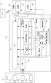
- FIG. 5 is a block diagram schematically showing the hierarchical structure of software in a vehicle (specifically, an in-vehicle device) and a server.
- FIG. 6 is a block diagram showing the functional configuration of the in-vehicle/outdoor communication unit shown in FIG. 3. As shown in FIG. FIG. FIG.
- FIG. 7 is a schematic diagram illustrating various delays in data transmission from the in-vehicle device to the server.
- FIG. 8 is a table showing parameters related to acquisition of moving image data.
- FIG. 9 is a flow chart showing processing related to uploading of moving image data executed by the vehicle interior/exterior communication unit.
- FIG. 10 is a flowchart showing a process of transmitting information used for uploading moving image data, which is executed by the in-vehicle/external linking unit, executed by the server.
- FIG. 11 is a diagram showing a state in which parameters are changed by time division.
- FIG. 12 is a flow chart showing processing related to uploading of moving image data executed by the vehicle interior/exterior communication unit according to the first modification.
- FIG. 13 is a block diagram showing functions of the vehicle interior/exterior communication unit according to the second modification.
- Patent Document 1 and Patent Document 2 consider the available communication band in the communication line (that is, wireless section), but the delay time of the in-vehicle device (for example, the delay time due to the load of the internal network, etc.) ) is not considered.
- the delay time of the in-vehicle device for example, the delay time due to the load of the internal network, etc.
- the present disclosure provides an in-vehicle device that can transmit data that can be effectively used by a service provided by the external device, taking into consideration the delay time and communication band.
- An object is to provide an apparatus, a control method and a computer program.
- An in-vehicle device is an in-vehicle device that is mounted in a vehicle and that transmits transmission data to a roadside device that is a device located outside the vehicle; An estimating unit that estimates the available bandwidth and end delay time that can be used in wireless communication with the roadside device, and the parameters that are used when generating the transmission data transmitted from the transmitting unit from the transmission target data. A determination unit that determines to satisfy the available bandwidth and the end delay time, and a generation unit that generates transmission data from the transmission target data using the parameters, and the end delay time is determined after the transmission target data is generated. It is the time until the transmitted data is delivered to the program that implements the service provided by the roadside device. As a result, when uploading data to an external device such as a roadside device, it is possible to transmit data that can be effectively used by the service provided by the external device, taking into consideration the delay time and communication bandwidth.
- the data to be transmitted may include moving image data obtained from a sensor mounted on a vehicle, and the parameters are the compression rate, resolution, frame rate, and bit rate of the transmission data. at least one of Thereby, the moving image data acquired from the sensor can be transmitted so as to satisfy the available bandwidth and the end delay time.
- the data to be transmitted may include moving image data acquired from each of a plurality of sensors mounted on the vehicle, and the determination unit includes a plurality of sensors according to the service provided by the roadside device, and the generation unit transmits moving image data obtained from each of the plurality of sensors according to the priority data may be generated.
- moving image data obtained from a plurality of sensors can be appropriately used by services provided by the roadside device.
- the priority may be a ratio of a communication band used for transmitting moving image data acquired from each of the plurality of sensors to the roadside device, and the determining unit , parameters may be determined for each moving image data so as to satisfy the communication bandwidth and end delay time determined from the available bandwidth and ratio. This makes it possible to efficiently determine an appropriate bit rate for transmitting moving image data obtained from each sensor to the roadside device.
- the available band is the communication speed estimated from the communication line quality of wireless communication and the on-vehicle device permitted in the provided wireless communication service. It may be a lower communication speed than the upper limit communication speed. This makes it possible to appropriately determine the parameters used when uploading data to an external device such as a roadside device.
- the generating unit may repeatedly determine the parameter with a predetermined period, and the predetermined period is a radio communication channel in radio communication. and at least one of the fluctuation period of the communication speed inside the vehicle. This makes it possible to appropriately determine the parameters used when uploading data to an external device such as a roadside device.
- the transmission target data can also be used by a function control device mounted on the vehicle. As a result, it is possible to avoid a situation in which the function control device cannot use the sensor data in order to transmit the sensor data to the roadside device.
- the transmitting unit may transmit the predetermined data before transmitting the transmission data
- the estimating unit may transmit the predetermined data when the predetermined data is transmitted.
- the predetermined data may include analysis results of sensor data obtained from sensors installed in the vehicle or data relating to the vehicle. This makes it possible to suppress data transmission for estimating the available bandwidth.
- the estimating unit determines the next usable Bandwidth may be estimated. As a result, unnecessary data transmission can be suppressed. This makes it possible to suppress data transmission for estimating the available bandwidth.
- the determination unit may determine parameters corresponding to each request, and the generation unit generates transmission data and the transmission unit transmits the transmission data to the roadside device for a predetermined period for each request. good too. As a result, data that can be effectively used by each service can be transmitted.
- the estimator may use the result of an AND operation of multiple requests to determine the parameters. Thereby, the data transmitted to the roadside device can be effectively used by any service.
- the transmission unit may transmit the transmission data to the roadside device in response to the occurrence of the event, and the event is the vehicle and/or the traffic conditions surrounding the vehicle. This makes it possible to reduce the amount of data transmitted within a certain period of time, compared to periodic transmission.
- the transmission unit may transmit the transmission data to the roadside device in response to the occurrence of an event, the event being the driving state of the vehicle and traffic conditions around the vehicle. It may relate to at least one of the states, and the ratio may change in response to the event occurring. As a result, it is possible to reduce the amount of data transmitted within a certain period of time compared to the case of periodic transmission, and to transmit appropriate sensor data according to the situation.
- the roadside device includes a communication unit that communicates with the in-vehicle device and observes the state of the service to be provided. and an infrastructure cooperation unit that specifies an allowable delay time that can be used for estimating the end delay time, and the communication unit transmits the allowable delay time to the in-vehicle device.
- the on-vehicle device that receives the allowable delay time can determine appropriate parameters to use when generating transmission data from the sensor data acquired from the own vehicle's sensors, and the data uploaded to the road-side device is provided by the road-side device. can be effectively used by services that
- a control method is a control method for an in-vehicle device mounted on a vehicle, comprising a transmission step of transmitting transmission data to a roadside device that is a device located outside the vehicle; , an estimation step of estimating an available bandwidth and an end delay time that the in-vehicle device can use in wireless communication with the roadside device; is determined so as to satisfy the available bandwidth and the end delay time, and a generation step of generating transmission data from the data to be transmitted using the parameters, and the end delay time is the time when the data to be transmitted is generated. to the time the transmitted data is passed to the computer program that implements the service provided by the roadside device.
- the in-vehicle device can transmit data that can be effectively used by the service provided by the external device, taking into consideration the delay time and communication band.
- a computer program includes a computer mounted on a vehicle, a transmission function of transmitting transmission data to a roadside device that is a device located outside the vehicle, and Estimation function for estimating available bandwidth and end delay time available in wireless communication, and parameters used when generating transmission data to be transmitted by the transmission function from data to be transmitted.
- a determination function that determines to satisfy the delay time and a generation function that generates transmission data from transmission target data using parameters are realized.
- the computer in-vehicle device
- the computer can transmit data that can be effectively used by the service provided by the external device, taking into consideration the delay time and communication bandwidth. .
- the cooperation system includes in-vehicle devices 100 and 110 mounted in vehicles 102 and 112, respectively, a base station 104, and a server .
- the base station 104 is connected to a network 108 such as the Internet.
- Base station 104 is a base station for wide area communication such as cellular communication.
- the base station 104 provides mobile communication services by, for example, LTE (Long Term Evolution), 4G (that is, fourth generation mobile communication system) lines, and 5G (that is, fifth generation mobile communication system) lines.
- LTE Long Term Evolution
- 4G that is, fourth generation mobile communication system
- 5G that is, fifth generation mobile communication system
- Each of in-vehicle device 100 and in-vehicle device 110 and server 106 can communicate with each other via base station 104 and network 108 .
- the base station 104 may provide wireless communication functions such as Wi-Fi and CV2X (Cellular-Vehicle to Everything).
- Each of vehicle 102 and vehicle 112 is equipped with a sensor such as an image sensor, and sensor data output from the sensor is acquired by in-vehicle device 100 and in-vehicle device 110 and transmitted to server 106 (hereinafter also referred to as upload). ) is done.
- the server 106 executes services such as provision of driving support information, remote monitoring and remote control, and uses sensor data received from the in-vehicle device 100 and the in-vehicle device 110 for the provided services.
- the server 106 may be a device arranged outside the vehicle 102 and the vehicle 112, or may be a roadside device fixedly installed on the road or its surroundings.
- FIG. 1 exemplarily shows one base station 104 and two vehicles 102 and 112 on which in-vehicle devices are mounted. But this is only an example. Usually, a plurality of base stations are provided, and in-vehicle devices are installed in three or more vehicles. There may be vehicles that are not equipped with an in-vehicle device. A vehicle without an in-vehicle device is a detection target of a sensor installed in a vehicle with an in-vehicle device.
- FIG. 2 shows a communication unit 120, a sensor 124, an automatic driving ECU 126, an ECU 128, and a bus 130 mounted on the vehicle 102.
- the vehicle 102 is equipped with a plurality of ECUs as devices (that is, function control devices) for controlling various functions of the vehicle.
- the automatic driving ECU 126 is one of the function control devices.
- a plurality of ECUs are mounted on the vehicle 102 in addition to the automatic driving ECU 126, and FIG. 2 shows an ECU 128 as a representative of them.
- the communication unit 120 performs wireless communication with devices outside the vehicle 102 via the base station 104 .
- the communication unit 120 includes an IC (Integrated Circuit) for performing modulation and multiplexing adopted in the wireless communication service provided by the base station 104, an antenna for transmitting and receiving radio waves of a predetermined frequency, and an RF Including circuits, etc.
- the communication unit 120 also has a function of communicating with GNSS (Global Navigation Satellite System) such as GPS (Global Positioning System).
- GNSS Global Navigation Satellite System
- GPS Global Positioning System
- the in-vehicle/outside cooperation unit 122 plays a role (for example, communication protocol conversion, etc.) that connects the communication function (ie, communication specification) with outside the vehicle and the communication function (ie, communication specification) inside the vehicle.
- the automatic driving ECU 126 can communicate with external devices via the vehicle interior/exterior communication unit 122 and the communication unit 120 .
- the vehicle interior/exterior cooperation unit 122 transfers the driving support information received from the outside via the communication unit 120 to the automatic driving ECU 126 .
- the bus 130 has a communication function inside the vehicle.
- Mutual communication that is, data exchange
- a bus 130 with respect to the in-vehicle/outdoor communication unit 122 , the sensor 124 , the automatic driving ECU 126 and the ECU 128 .
- Ethernet registered trademark
- CAN Controller Area Network
- the sensors 124 are mounted on the vehicle 102 and include sensors for acquiring information inside and outside the vehicle 102 .
- Sensors for acquiring information outside the vehicle include imaging devices (e.g., digital cameras (e.g., CCD cameras or CMOS cameras)), radars (e.g., millimeter wave radars, etc.), and laser sensors (e.g., LiDAR (Light Detection And Ranging)). etc.
- a sensor for obtaining information in the vehicle includes an imaging device.
- the sensor 124 acquires information within a detection range (for example, an imaging range in the case of a camera) and outputs it as sensor data.
- a digital camera outputs digital moving image data.
- a detection signal (that is, an analog or digital signal) of the sensor 124 is output to the bus 130 as digital data via an I/F unit (not shown), and is transmitted to the vehicle interior/exterior communication unit 122, the automatic driving ECU 126, and the like. be.
- the automatic driving ECU 126 controls the running of the vehicle 102.
- the autonomous driving ECU 126 acquires sensor data, analyzes it, grasps the situation around the vehicle, and controls mechanisms related to autonomous driving (for example, mechanisms such as the engine, transmission, steering, or brakes). do.
- the automatic driving ECU 126 uses driving support information (for example, dynamic information) acquired from the in-vehicle/outdoor communication unit 122 for automatic driving.
- vehicle interior/exterior communication unit 122 includes control unit 140 , memory 142 , I/F unit 144 and transmission data generation unit 146 .
- the control unit 140 includes a CPU (Central Processing Unit) and controls the memory 142 , the I/F unit 144 and the communication unit 120 . Control signals for this purpose are indicated by dashed arrows in FIG.
- the memory 142 is, for example, a rewritable non-volatile semiconductor memory, and stores computer programs (hereinafter simply referred to as programs) executed by the control unit 140 .
- Memory 142 provides a work area for programs executed by control unit 140 .
- the I/F section 144 is controlled by the control section 140 and interfaces with the sensor 124 (see FIG. 2). If the sensor 124 is a camera that outputs moving image data and it is possible to set a plurality of imaging conditions (for example, the resolution and frame rate of the output data), the control unit 140 controls the camera via the I/F unit 144. Set the imaging conditions. Under the control of the control unit 140 , the transmission data generation unit 146 generates transmission data from sensor data acquired from the sensor 124 and stored in the memory 142 . This sensor data is data to be transmitted to the server 106 (hereinafter also referred to as transmission target data). For example, if the sensor data is moving image data, the amount of data is large.
- transmission target data data to be transmitted to the server 106 (hereinafter also referred to as transmission target data). For example, if the sensor data is moving image data, the amount of data is large.
- the transmission data generator 146 converts the resolution and frame rate, and compresses the data so as not to constrict the communication band. If the transmission data generation unit 146 can generate transmission data from sensor data based on a plurality of conditions, the control unit 140 designates conditions (for example, resolution, frame rate, compression ratio, etc.) to the transmission data generation unit 146 . The transmission data generator 146 generates transmission data based on specified conditions. The generated transmission data is stored in memory 142 . The communication unit 120 is controlled by the control unit 140 to generate packet data from transmission data stored in the memory 142 and transmit the packet data. If the sensor data is moving image data, a predetermined amount of data sequentially acquired from the sensor 124 is buffered in the memory 142, and transmission data is generated from the buffered data and transmitted sequentially.
- the control unit 140 designates conditions (for example, resolution, frame rate, compression ratio, etc.) to the transmission data generation unit 146 .
- the transmission data generator 146 generates transmission data based on specified conditions.
- the generated transmission data is
- server 106 includes control unit 160 , memory 162 , communication unit 164 and bus 166 . Data transfer between units occurs via bus 166 .
- the control unit 160 includes a CPU, controls each unit, and implements various services.
- Communication unit 164 receives information (including sensor data, vehicle information, etc.) uploaded from in-vehicle device 100 and in-vehicle device 110 via base station 104 and network 108 .
- the memory 162 includes a rewritable non-volatile semiconductor memory and a mass storage device such as a HDD (Hard Disk Drive). The data received by communication unit 164 is transferred to memory 162 and stored therein.
- HDD Hard Disk Drive
- the data uploaded and stored in memory 162 is used by an application program (hereinafter simply referred to as an application) for implementing services.
- the communication unit 164 has a function of accessing the network 108 wirelessly or by wire. Under the control of control unit 160 , communication unit 164 transmits request data and the like to vehicle 102 and vehicle 112 from memory 162 .
- Server 106 includes an operation unit (not shown) such as a computer keyboard and mouse for the administrator or the like to input instructions to control unit 160 .
- the software of the cooperation system configured by vehicle 102 and server 106 is hierarchically configured.
- the hierarchical structure shown in FIG. 5 corresponds to, for example, the hierarchical structure of the OSI (Open Systems Interconnection) reference model.
- the vehicle 102 includes a plurality of ECUs as described above, and includes application programs (first-ECU application to second M-ECU application) for realizing the functions of each ECU in the upper layer.
- the upper layer applications are executed in parallel by a microcomputer or the like mounted on each ECU.
- a higher layer corresponds to, for example, the application layer of the OSI reference model.
- the vehicle 102 includes a communication stack responsible for communication with the outside (for example, below the session layer of the OSI reference model) in the lower layer, and a sublayer program that mediates between the upper layer program and the lower layer program in the middle layer.
- the middle layer corresponds, for example, to the presentation layer of the OSI reference model.
- the functions (or corresponding programs) of the in-vehicle/outdoor communication unit 122 of the in-vehicle device 100 are mainly positioned as sub-layer programs.
- the vehicle interior/exterior cooperation unit 122 controls the lower layer communication stack, and transmits sensor data such as moving image data to the server 106 as described above.
- the vehicle interior/exterior cooperation unit 122 controls the communication stack of the lower layer, and receives request data from the server 106 regarding transmission of sensor data such as moving image data, as will be described later.
- the vehicle interior/exterior cooperation unit 122 controls the lower layer communication stack, receives service data (for example, driving support information, etc.) transmitted from the server 106 as described above, and receives, for example, the automatic driving ECU 126 (see FIG.
- the function (or corresponding program) of the in-vehicle/outdoor cooperation unit 122 may include a part of a plurality of upper-layer applications. That is, the vehicle interior/exterior communication unit 122 may include functions as an ECU.
- the server 106 executes a plurality of services (including driving support, remote monitoring, remote control, etc.) as described above, and application programs (first service application to Nth service application) for realizing each service in the upper layer. )including.
- the server 106 includes a communication stack responsible for communication with the outside (for example, the in-vehicle device 100 of the vehicle 102, etc.) in the lower layer, and sub-layer programs that mediate the upper layer program and the lower layer program in the middle layer. include.
- the upper layer, the middle layer and the lower layer respectively correspond to the layers below the application layer, the presentation layer and the session layer of the OSI reference model, respectively.
- a program for realizing an infrastructure cooperation unit for communicating with the in-vehicle device 100 of the vehicle 102 to configure a cooperation system is mainly positioned as a sublayer program.
- the upper layer and middle layer programs are executed as multitasks by the control unit 160 (see FIG. 4).
- the infrastructure cooperation unit controls the communication stack of the lower layer, receives sensor data such as moving image data transmitted from the vehicle 102 as described above, and passes it to the program of the upper layer.
- the infrastructure linking unit observes the operation of the upper layer programs and acquires the conditions required by them (for example, request data such as allowable delay time).
- the server 106 controls the lower layer communication stack and transmits the requested data.
- the infrastructure cooperation unit controls the communication stack of the lower layer, and transmits service data (for example, driving support information, etc.) provided by the program of the upper layer to the in-vehicle device 100 of the vehicle 102 .
- In-vehicle/outdoor cooperation unit 122 includes control unit 140, memory 142, I/F unit 144, and transmission data generation unit 146, as shown in FIG.
- Control unit 140 includes estimation unit 220 , determination unit 222 and communication control unit 224 , and determination unit 222 includes parameter determination unit 226 and priority determination unit 228 .
- Transmission data generation section 146 includes frame rate conversion section 210 , resolution conversion section 212 and compression section 214 .
- the sensor 124 includes cameras 200 , 202 and 204 . These cameras are arranged on the vehicle 102 so that the camera 200 images the front of the vehicle 102 , the camera 202 images the rear of the vehicle 102 , and the camera 204 images the interior of the vehicle 102 .
- Camera 200, camera 202, and camera 204 may be cameras with the same specifications or cameras with different specifications.
- camera 200 that captures an image in front of vehicle 102 may have a higher resolution than either camera 202 or camera 204 .
- Camera 204 that captures images of the interior of the vehicle may also include a microphone that detects sound.
- the imaging conditions (including resolution, frame rate, etc.) of cameras 200 , 202 and 204 can be set by control section 140 via I/F section 144 .
- the frame rate conversion unit 210 reads the moving image data stored in the memory 142 and converts the moving image data so that the frame rate specified by the parameter determination unit 226 is obtained. For example, if the frame rate of the moving image data stored in the memory 142 (that is, the frame rate of the output data of the sensor 124) is an integral multiple of the frame rate specified by the parameter determination unit 226, the original moving image data By thinning out the converted moving image data can be generated. If there is no corresponding frame, the frame data of the converted moving image data can be generated by interpolation processing using a plurality of adjacent frame data in the original moving image data. The moving image data after conversion is stored in the memory 142 .
- the resolution conversion unit 212 reads the moving image data stored in the memory 142 and converts (that is, resizes) the moving image data so that the resolution is specified by the parameter determination unit 226 . Specifically, the pixel data of the converted frame is generated from the pixel data of each frame by interpolation processing or the like. The moving image data after resolution change is stored in the memory 142 .
- the processing of the frame rate conversion unit 210 and the resolution conversion unit 212 even if the resolution conversion unit 212 is executed for the result of executing the frame rate conversion unit 210, the result of executing the resolution conversion unit 212 is A frame rate converter 210 may be executed.
- the compression unit 214 reads the moving image data stored in the memory and compresses it to reduce the data size.
- the compression unit 214 compresses the moving image data so that the ratio of the data size after compression (per unit time, for example) to the data size of the original image (per unit time, for example) is the compression rate specified by the parameter determination unit 226. to compress.
- MPEG Motion Picture Experts Group
- MPEG2, MPEG4, etc. can be used as the compression method.
- compressed moving image data does not have a data structure in frame units. Therefore, when changing either the frame rate or the resolution, the corresponding processing of the frame rate conversion unit 210 and the resolution conversion unit 212 is executed.
- the subsequent moving image data is compressed by the compression unit 214 .
- the moving image data after compression is stored in the memory 142 .
- the estimation unit 220 estimates the UL communication speed and end delay time when data is uploaded from the in-vehicle device 100 to the server 106 .
- the UL communication speed means the available band for wireless communication, that is, the wireless communication speed.
- the end delay time means the time from when sensor data is output from the sensors mounted on the vehicle to when it is handed over to the service application being executed by the server.
- the estimator 220 calculates a transmission delay from the estimated end delay time. Transmission delay is the time it takes for data to be sent from the vehicle's communications unit until it is received by the server and passed to the application performing the service. That is, the transmission delay is the end delay time minus the delay time in the vehicle (for example, the time during which sensor data is transmitted and processed).
- Estimating section 220 outputs the estimated UL communication speed and the calculated delay time to parameter determining section 226 .
- the estimation unit 220 determines the maximum communication speed X (bps unit) at which stable communication is possible through observation.
- the maximum communication speed X (bps unit) represents the quality of the wireless communication line (that is, the communication line quality).
- the estimation unit 220 transmits a pilot signal (hereinafter referred to as a pilot packet) of a predetermined amount of data (more specifically, data size of payload) before uploading moving image data to the server 106 .
- the estimation unit 220 can calculate the communication speed by dividing the amount of data transmitted as a pilot packet by the transmission time of the pilot packet.
- the transmission time is calculated from the time stamp included in the packet notifying normal reception transmitted from the server 106, can be calculated by subtracting the timestamp of when the transmission of If the in-vehicle device 100 and the server 106 are asynchronous (that is, the timers of both show different times), the estimating unit 220 executes, for example, a PING command, and the RTT (Round-Trip Time) included in the response , the communication speed can be calculated. That is, since RTT represents round-trip time, 1/2 of it can be used as transmission time.
- an upper limit Y (in units of bps) of the upload communication speed that can be used by one communication terminal is set.
- the upper limit value Y (in units of bps) of the communication speed may be stored in advance in the memory 142, for example.
- data other than moving image data (for example, data related to vehicles) is also uploaded from the in-vehicle device 100 to the server 106 .
- the estimation unit 220 can determine the communication speed a by observing actual data transmission.
- the communication speed a may be pre-stored in the memory 142 .
- the real-time property required by the service (that is, service application) provided by the server 106 is different, and the delay time allowed for the moving image data received by the server 106 (hereinafter referred to as "allowable delay time") is accordingly different.
- the upper limit of the end delay time is limited.
- Time T1 is the time required for data (for example, moving image data) periodically transmitted (that is, output) from the camera 200 in units of frames to reach the memory 142 after being output from the camera 200 (hereinafter referred to as transmission cycle (or referred to as an acquisition period).
- a transmission cycle (that is, a capture cycle) is represented by the reciprocal of the frame rate (fps unit) of moving image data. Since the moving image data output from the camera 200 is composed of frames, and subsequent processing is performed on the frames, the delay time is the time until processing becomes possible (that is, the transmission cycle).
- Time T2 and time T3 are times required for image capture and processing by processing unit 250 .
- Image capture and processing unit 250 corresponds to frame rate conversion unit 210, resolution conversion unit 212, and compression unit 214 shown in FIG.
- the time T2 is the time required for the moving image data to be stored in the memory 142 and for the compression process to start (that is, the image capture delay). Note that the time T2 includes the time required for converting the moving image data, for example, the time required for converting the frame rate and resolution.
- the time T3 is the time required for the process of compressing the converted moving image data (that is, the compression time).
- Time T4 is the time required for transmission data (that is, moving image data after compression) to be read from memory 142, transmitted through in-vehicle device 100 to communication unit 120, and ready for transmission by communication unit 120 (that is, other processing time). ).
- Time T5 is the transmission delay described above.
- the transmission delay can be calculated by the following equation.
- the end delay time depends on the service of the server 106 as described above, so information for estimating the end delay time can be obtained from the server 106 .
- the estimation unit 220 estimates the end delay time used in Equation 1 from the allowable delay time transmitted from the server 106 . Since the allowable delay time is the upper limit of the end delay time, the estimator 220 can set the allowable delay time to be the end delay time of Equation 1, for example.
- a value slightly smaller than the allowable delay time may be set as the end delay time in Equation (1).
- the time T1 (that is, transmission period) is determined by the frame rate of the camera. Since time T2 to time T4 depends on the target data size (for example, resolution), if values corresponding to the data size (for example, measured values) are stored in advance in the memory 142 as a table, the estimating unit 220 uses the table , the time T2 to time T4 can be determined. Note that the time T3 (that is, the compression time) also depends on the compression ratio, so it is preferable that the table also considers the compression ratio.
- time T1 to T5 the ratio of each of the time T1 to the time T5 to the end delay time is the largest in the time T5 (that is, the transmission delay) (usually several hundred milliseconds to several seconds).
- the time T1 to T4 other than time T5 is considered to be less than 100 milliseconds. Therefore, time T1 to time T4 may be set to fixed values.
- the priority determining unit 228 determines the priority of multiple sensors (ie, camera 200, camera 202 and camera 204).
- the priority indicates which of the output data of a plurality of sensors is to be uploaded with priority.
- the priority determination unit 228 determines the ratio of the communication band (that is, communication speed) to be allocated for uploading the output data (that is, moving image data) of each sensor according to the running state of the vehicle 102 and the request from the server 106. do.
- the request from the server 106 is a request from the viewpoint that the server 106 uses the moving image data uploaded from the in-vehicle device 100 (that is, output data from the cameras 200, 202 and 204).
- Requests from server 106 depend, for example, on programs (ie, service applications) running on server 106 .
- programs ie, service applications
- a communication band is also allocated to the camera 204 that captures images of the interior of the vehicle.
- the priority may be designated from the outside of the in-vehicle device 100 (for example, an operation unit).
- the priority determination section 228 outputs the determined priority (that is, ratio) to the parameter determination section 226 .
- the parameter determining unit 226 determines the bit rate when uploading the sensor data (that is, moving image data) for each of the plurality of sensors (that is, camera 200, camera 202, and camera 204), and determines parameters related to moving image data. do. Parameters include frame rate, resolution and compression ratio.
- the parameter determination unit 226 outputs the determined parameters to the frame rate conversion unit 210, the resolution conversion unit 212 and the compression unit 214, and operates the frame rate conversion unit 210, the resolution conversion unit 212 and the compression unit 214 as described above. .
- transmission data is generated from moving image data, which is data to be transmitted.
- the parameters are parameters related to transmission data, not parameters related to moving image data output from cameras 200 , 202 , and 204 .
- the compression rate is the data size (for example, per unit time) of transmission data with respect to the data size (for example, per unit time) of moving image data output from cameras 200 , 202 and 204 .
- the moving image data after the transmission data is received by the server 106 and decompressed has the frame rate and resolution specified by the parameters.
- the parameter determination unit 226 assigns communication speeds (hereinafter referred to as allocation UL communication speed). That is, the parameter determining unit 226 proportionally distributes the UL communication speed input from the estimating unit according to the ratio input from the priority determining unit 228, and calculates each allocated UL communication speed. Subsequently, the parameter determining unit 226 multiplies each assigned UL communication speed by the transmission delay input from the estimating unit 220 to calculate (that is, determine) the bit rate at the time of transmission for each piece of moving image data.
- the bit rate is the upper limit of the amount of data that can be transmitted from the in-vehicle device 100 to the server 106 during transmission delay.
- the transmitted data ie moving image data
- the transmission data amount per unit time is larger than the determined bit rate, the data cannot be transmitted during the transmission delay, and the end delay time exceeds the allowable delay range of the service provided by the server 106. Therefore, the transmitted data (ie moving image data) is not effectively used by the services provided by the server 106 .
- the parameter determining unit 226 determines the parameters of the moving image data (that is, frame rate, resolution and compression ratio) so that the bit rate is equal to or less than the determined bit rate for each camera.
- the amount of moving image data per unit time includes the number of pixels in one frame (that is, the product of the number of vertical pixels and the number of horizontal pixels), the amount of data in one pixel (for example, 24 bits), the compression ratio, and the frame rate (that is, , number of frames per unit time). Normally, the amount of data for one pixel of a camera is fixed.
- the number of pixels in one frame is determined by the resolution, that is, the number of vertical and horizontal pixels. Therefore, a table as shown in FIG.
- the parameter determination unit 226 refers to the table to determine a combination of parameters whose data amount per unit time (that is, the moving image data amount shown in FIG. 8) is equal to or less than the bit rate and has the value closest to the bit rate. can. In FIG. 8, the ID is given a unique value for each parameter set. If there are a plurality of parameter sets with the same moving image data amount, one parameter set may be determined according to a predetermined criterion. For example, if real-time performance is required, a parameter set with a higher frame rate can be selected. A parameter set with a higher resolution or a lower compression rate can be selected when high accuracy in detecting an object is required.
- the resolution may have any number of pixels, but may have the number of pixels normally used.
- SD Standard Definition
- HD High Definition
- FHD Full High Definition
- 4K etc.
- SD is an image with 720 horizontal pixels and 480 vertical pixels
- HD is an image with 1280 horizontal pixels and 720 vertical pixels
- Full-HD is an image with 1920 horizontal pixels and 1080 vertical pixels
- 4K is an image with 3840 horizontal pixels and 1080 vertical pixels. It means an image of 2160 vertical pixels.
- some parameters may be fixed. For example, at least one of compression rate and frame rate may be fixed. In that case, by changing at least the resolution, the amount of data per unit time (that is, the amount of moving image data shown in FIG. 8) can be reduced below the required bit rate.
- the communication control unit 224 controls the receiving unit 242 and the transmitting unit 240 of the communication unit 120 to communicate with external devices. Specifically, the communication control unit 224 controls the receiving unit 242 and the transmitting unit 240 to transmit a pilot packet and receive a normally received packet from the server 106 as described above. Also, the communication control unit 224 may control the receiving unit 242 and the transmitting unit 240 to transmit PING packets and receive responses thereto, as described above. The communication control unit 224 controls the reception unit 242 to receive requests (for example, the allowable delay time and camera priority) transmitted from the server 106 and store them in the memory 142 .
- requests for example, the allowable delay time and camera priority
- the communication control unit 224 controls the transmission unit 240 of the communication unit 120 to transmit the transmission data generated by the frame rate conversion unit 210, the resolution conversion unit 212 and the compression unit 214 to the server 106.
- the communication control unit 224 may transmit data periodically at regular time intervals, or may transmit data in response to a trigger generated when some event occurs.
- the in-vehicle/outdoor cooperation unit 122 considers the available band for wireless communication (that is, the wireless communication speed) and the end delay time, and determines the priority of each of the plurality of sensors (camera 200, camera 202, and camera 204).
- parameters for generating transmission data from moving image data can be determined according to . That is, when uploading data to an external device such as a roadside device (for example, the server 106), it is possible to transmit data that can be effectively used by the service provided by the external device, taking into consideration the delay time and communication bandwidth.
- a roadside device for example, the server 106
- the present invention is not limited to this.
- it is not limited to transmission data generated from sensor data. It may be an analysis result of sensor data or the like.
- the in-vehicle/external linking unit 122 uses compression of transmission data as a parameter for generating transmission data from moving image data acquired from a sensor mounted on the vehicle. rate, resolution and frame rate. Therefore, moving image data acquired from the sensor can be transmitted so as to satisfy the available bandwidth and the end delay time.
- the bit rate at the time of transmission for each moving image data is calculated (that is, determined), and parameters (that is, compression rate, resolution and frame rate) has been described, but the present invention is not limited to this.
- the bit rate itself may be used as a parameter.
- the bit rate may be limited to a predetermined value or less in order to suppress transmission of unnecessary large-capacity data (for example, high-quality data). That is, an upper limit value is set for the bit rate, and if the bit rate determined as described above exceeds the preset upper limit value, the parameter determination unit 226 replaces the determined bit rate with the upper limit value.
- the parameters of moving image data may be determined as follows. Therefore, the parameter may be at least one of compression rate, resolution, frame rate and bit rate for the transmitted data.
- the in-vehicle/outdoor cooperation unit 122 determines the priority of the sensor that acquires the transmission target data used to generate the transmission data from among the plurality of sensors. Determined according to the service provided. Therefore, moving image data obtained from multiple sensors can be appropriately used by the services provided by the roadside device.
- the in-vehicle/exterior cooperation unit 122 determines the communication band used for transmitting the moving image data acquired from each of the plurality of sensors to the roadside device as the priority. Use ratios. Therefore, it is possible to efficiently determine an appropriate bit rate for transmitting moving image data acquired from each sensor to the roadside device.
- the in-vehicle/external cooperation unit 122 determines the communication speed estimated from the communication line quality of wireless communication and the upper limit allowed for the in-vehicle device in the provided wireless communication service.
- the available bandwidth that is, the UL communication speed
- the UL communication speed is determined from the smaller communication speed. Therefore, it is possible to appropriately determine the parameters used when uploading data to an external device such as a roadside device.
- Each functional block shown in FIG. 6 can be realized by hardware, software, or a mixture thereof.
- the processing executed by the frame rate conversion unit 210, the resolution conversion unit 212, the compression unit 214, the estimation unit 220, the parameter determination unit 226, and the priority determination unit 228 are executed.
- dedicated hardware for example, a circuit board or an ASIC (Application Specific Integrated Circuit), etc.
- the control unit 140 may execute a predetermined program (see FIG. 9), as will be described later.
- FIG. 9 the operation of the vehicle interior/exterior communication unit 122 will be described with reference to the functions shown in FIG.
- the processing shown in FIG. 9 is implemented by control unit 140 shown in FIG. 3 reading out a predetermined program from memory 142 and executing the program.
- the processing shown in FIG. 9 is started when the in-vehicle device 100 is instructed to upload sensor data (that is, moving image data).
- An instruction to upload can be made by turning on the power of the in-vehicle device 100 or by giving an explicit instruction to the in-vehicle device 100 via the operation unit.
- the upper limit value Y (bps unit) of the upload communication speed that can be used by one communication terminal is stored in the memory 142 . Further, it is assumed that predetermined values are stored in the memory 142 as fixed values from time T1 to time T4. Assume that the memory 142 also stores a table for determining parameters (ie, frame rate, resolution and compression ratio) as shown in FIG.
- control unit 140 controls the communication unit 120 and determines whether or not a service request has been received from the server 106 . If so, control proceeds to step 302 . Otherwise control passes to step 314 .
- a service request is sent from the server 106 and is a request (eg, acceptable delay time and priority) of the application program that the server 106 is executing.
- control unit 140 stores the service request received at step 302 in the memory 142 . Control then passes to step 304 .
- control unit 140 estimates the UL communication speed Z. This corresponds to the function of the estimation unit 220 described above.
- Control unit 140 measures maximum communication speed X (in units of bps), reads upper limit value Y (in units of bps) of the upload communication speed from memory 142, and determines the communication speed assigned to transmission of data other than moving image data.
- the control unit 140 estimates the end delay time and calculates the transmission delay as described above. This corresponds to the function of the estimation unit 220 described above.
- the control unit 140 reads the service request (that is, the allowable delay time) and the times T1 to T4 from the memory 142, estimates the end delay time from the allowable delay time, and subtracts the sum of the times T1 to T4 from the end delay time. to calculate the transmission delay. Control then passes to step 308 .
- the control unit 140 determines the UL communication speed (that is, the assigned UL communication speed) for each sensor. This corresponds to the function of the parameter determining section 226 described above.
- the control unit 140 reads the service request (that is, priority) from the memory 142, proportionally distributes the UL communication speed determined in step 304 according to the priority, and determines the allocated UL communication speed.
- the priority is, for example, the ratio of the communication band to be allocated, and as described above, the server 106 transmits, for example, the ratios for the front camera, rear camera, and in-vehicle camera. Control then passes to step 310 .
- control unit 140 uses the allocated UL communication speed determined at step 310 and the transmission delay estimated at step 306 to determine the bit rate for each sensor. This corresponds to the function of the parameter determining section 226 described above.
- the control unit 140 multiplies the assigned UL communication speed by the transmission delay to determine the bit rate for transmitting the moving image data acquired by each sensor. Control then passes to step 312 .
- control unit 140 uses each bit rate determined at step 310 to refer to the table stored in the memory 142 and determines parameters for each sensor. This corresponds to the function of the parameter determining section 226 described above. Control then passes to step 314 .
- the determined parameters are stored in memory 142 . For example, in the case of a table as shown in FIG. 8, control unit 140 stores in memory 142 information specifying the ID of the determined parameter set.
- control unit 140 determines whether or not to transmit (ie, upload) the sensor data (that is, moving image data) acquired from each sensor to the server 106 . If so, control passes to step 316 . Otherwise control passes to step 318 . For example, if it is set to periodically upload at a certain time interval ⁇ T, the control unit 140 acquires the current time, and if the time ⁇ T has passed since the previous upload, the transmission If it does not pass, it is determined not to transmit. The control unit 140 acquires the current time from the timer inside the in-vehicle device 100 .
- control unit 140 reads the parameters determined at step 312 from the memory 142, and according to the parameters, generates transmission data from sensor data (that is, moving image data). Control unit 140 controls communication unit 120 and transmits the generated transmission data to server 106 . Control then passes to step 318 . Note that if the control unit 140 has never received a service request, the control unit 140 generates transmission data using default parameters. Default parameters may be stored in memory 142 in advance.
- control unit 140 determines whether or not an end instruction has been received. If it is determined that an end instruction has been received, this program ends. Otherwise, control returns to 300 and the process described above is repeated.
- the end instruction is made, for example, by turning off a power supply installed in the vehicle 102 .
- the in-vehicle/outdoor cooperation unit 122 considers the available band for wireless communication (that is, the wireless communication speed) and the end delay time, and converts the transmission data from the moving image data according to the priority of each of the plurality of sensors. can determine the parameters for generating Transmission data is generated using the determined parameters and uploaded to the server 106 so that the server 106 can make better use of the received sensor data by the services it provides.
- control unit 160 determines whether or not to start a service that uses sensor data (that is, moving image data) uploaded from the in-vehicle device.
- the service is started, for example, according to a predetermined schedule, or by an administrator's instruction by operating the operation unit of the server 106 . If so, control passes to step 402 . Otherwise control passes to step 404 .
- Services include, for example, provision of driving support information, remote monitoring and remote control.
- control unit 160 activates the applicable application. Control then passes to step 404 .
- the control unit 160 determines whether to transmit a service request.
- the service request includes the delay time required for the running service to effectively use the uploaded data (that is, the allowable delay time), the priority of the in-vehicle sensor (eg, camera), and the like. If so, control passes to step 406 . Otherwise control passes to step 408 . For example, if any upload data is available to the service application, it is determined not to send the service request.
- control unit 160 transmits a service request.
- the transmission is performed, for example, by broadcasting.
- Control then passes to step 408 .
- the transmitted request is used by the vehicle-mounted device that receives it to determine the parameters as described above.
- control unit 160 determines whether sensor data (for example, moving image data) has been received. If so, control passes to step 410 . Otherwise, control transfers to step 412 .
- sensor data for example, moving image data
- control unit 160 passes the sensor data received at step 408 to the running service application. Control then passes to step 412 .
- the control unit 160 notifies the service application of access information (eg, memory address, etc.) to the sensor data stored in the memory 162 .
- the service application accesses the memory 162 and acquires sensor data. If the received sensor data satisfies the service request sent from the server 106, the service application can effectively use the sensor data.
- control unit 160 determines whether or not to terminate the service being executed.
- the service is terminated, for example, according to a predetermined schedule or by the administrator operating the operation unit of the server 106 to give an instruction. If so, control passes to step 414 . Otherwise control passes to step 416 .
- control unit 160 terminates the corresponding service application. Control then passes to step 416 .
- control unit 160 determines whether or not an end instruction has been received. If it is determined that an end instruction has been received, this program ends. Otherwise, control returns to step 400 and the above process is repeated.
- An instruction to end is made by, for example, the operation unit of the server 106 being operated by an administrator or the like.
- the server 106 sends a service request (for example, an allowable delay time and priority, etc.) can be sent.
- a service request for example, an allowable delay time and priority, etc.
- the in-vehicle device that receives the service request can determine the appropriate parameters to use when generating transmission data from the sensor data obtained from the own vehicle's sensors, and the data uploaded to the server 106 is effective according to the service provided by the server 106. can be used for
- the in-vehicle/exterior linking unit 122 and the server 106 operate in cooperation, so that the in-vehicle/outside linking unit 122 considers the available band for wireless communication (that is, the wireless communication speed) and the end delay time.
- parameters for generating transmission data from moving image data can be determined according to the priority of each of the plurality of sensors. That is, when uploading data to an external device such as a roadside device (for example, the server 106), it is possible to transmit data that can be effectively used by the service provided by the external device, taking into consideration the delay time and communication bandwidth.
- the control section 140 may determine whether or not a trigger requesting an upload has occurred. For example, when a specific traffic situation occurs (for example, an accident occurs), or when the vehicle 102 enters a specific running state (for example, entering an intersection), the automatic driving ECU 126 or the ECU 128 (see FIG. 2) ) can be made to output a trigger.
- a specific traffic situation for example, an accident occurs
- a specific running state for example, entering an intersection
- the automatic driving ECU 126 or ECU 128 analyzes moving image data acquired from the camera 200 and the camera 202 that capture images of the outside of the vehicle, and detects objects requiring attention on road traffic (for example, traffic signs, pedestrians, red lights, etc.). can be detected.
- road traffic for example, traffic signs, pedestrians, red lights, etc.
- a trigger may be output when any one or a combination of these is detected. In the case of event transmission, the amount of data transmitted within a certain period can be reduced more than in the case of periodic transmission.
- the ratio of the communication band allocated to the in-vehicle cameras 200, 202, and 204 for transmission may be changed. For example, when entering an intersection, the camera 200 that images the front is given priority (that is, a higher ratio is assigned), and when leaving the intersection, the camera 204 that images the rear is given priority (that is, a higher ratio is assigned). good too. Accordingly, appropriate sensor data can be transmitted depending on the situation.
- the in-vehicle/external linking unit 122 selects the moving image data to be uploaded.
- the parameters for generation can be appropriately determined. Therefore, the uploaded data can be effectively used by multiple applications.
- the requirements eg, acceptable delay time, etc.
- some service applications will not be able to effectively utilize the received data if the same parameters are used.
- the internal/external linking unit 122 classifies the application programs according to the degree of approximation of the requests, determines different parameters for each request, and time-divides them as shown in FIG. Then, upload to the service application corresponding to each request. That is, the in-vehicle/outdoor cooperation unit 122 generates and uploads transmission data from the moving image data using the first parameter set during the period ⁇ T1. The uploaded data is passed to the corresponding service application. During a period ⁇ T2 following the period ⁇ T1, the vehicle interior/exterior cooperation unit 122 generates and uploads transmission data from the moving image data using the second parameter set. The uploaded data is passed to the corresponding service application.
- a period ⁇ T1 in which the first parameter set is used and a period T2 in which the second parameter set is used are repeated.
- the length of the period ⁇ T1 and the period ⁇ T2 may be the same or different. Even if there are three or more types of allowable delay times (that is, three or more parameter sets), the vehicle interior/exterior communication unit 122 may similarly increase the number of divisions and sequentially use different parameter sets by time division. This makes it possible to transmit data that can be effectively used by each service application.
- the in-vehicle/exterior linking unit 122 may perform an AND operation on a plurality of requests, determine parameters using the result, and generate transmission data from moving image data using the parameters. . If the request is an allowable delay time, the smallest allowable delay time is determined by the AND operation of a plurality of requests. decide.
- the uploaded data is passed to all service applications running on server 106 . The uploaded data meets the most stringent requirements and can be effectively used by any service application.
- a port number is used to identify a service application that delivers uploaded sensor data that satisfies a predetermined request from among multiple service applications running on the server 106 . That is, when a service request is transmitted from the server 106, the port number of the corresponding service application is added and transmitted, and when the in-vehicle device that receives the service request uploads the sensor data, the port number is added and uploaded. . This allows the server 106 to identify the service application corresponding to the port number added to the received sensor data.
- the control unit 140 may store the port number added to the received service request in the memory 142 in association with the service request (see step 302 in FIG. 9). The control unit 140 can specify the corresponding port number when transmitting the transmission data generated using the parameters determined according to the service request, and can add the specified port number to the transmission data (step in FIG. 9). 316).
- transmission data is generated by the frame rate conversion unit 210 and the resolution conversion unit 212 using the determined parameters (that is, frame rate and resolution).
- Camera 200, camera 202, and camera 204 may have the function of changing the frame rate and resolution to output moving image data.
- the control unit 140 may instruct the camera 200, the camera 202, and the camera 204 via the I/F unit 144 to output moving image data based on the determined parameters (ie frame rate and resolution). .
- the in-vehicle/outdoor cooperation unit 122 does not have to include the frame rate conversion unit 210 and the resolution conversion unit 212 .
- the frame rate used by the frame rate conversion unit 210 and the frame rate used by the frame rate conversion unit 210 and The resolution used by the resolution converter 212 may be determined.
- the server 106 transmits a service request (e.g., allowable delay time, priority, etc.), and using it to determine parameters used to generate transmission data to be uploaded by the in-vehicle device.
- a service request e.g., allowable delay time, priority, etc.
- the in-vehicle device knows the content of the service provided by the server 106, the in-vehicle device independently determines (i.e., guesses) the service request (for example, the allowable delay time, priority, etc.) and parameters may be determined in
- FIG. 12 shows a flowchart in which step 340 is added to the flowchart of FIG.
- the processing contents of the steps with the same reference numerals as in the flowchart of FIG. 9 are the same as those of FIG.
- an in-vehicle device that executes the flowchart shown in FIG. 12 is configured in the same manner as in FIGS.
- the processing shown in FIG. 12 is implemented by control unit 140 shown in FIG. 3 reading out a predetermined program from memory 142 and executing the program. Therefore, description will be made mainly on the points of difference without repeating redundant description.
- control unit 140 determines whether or not a service request has been received from the server 106. If it is determined that a service request has been received, control proceeds to step 302. This determines the parameters (ie frame rate, resolution and compression ratio) as described above. On the other hand, if it is determined that it has not been received, control proceeds to step 340 .
- control unit 140 determines whether or not to update the parameters. If so, control passes to step 304 where the parameters (ie frame rate, resolution and compression ratio) are determined as described above. Otherwise control passes to step 314 .
- the parameters ie frame rate, resolution and compression ratio
- Parameters may be updated at regular intervals or according to a predetermined schedule. Since the communication speed may change with fluctuations in the wireless communication channel, it is preferable to set the update period in consideration of the fluctuation period of the wireless communication channel when the parameter is updated at regular intervals.
- the fluctuation period of a wireless communication channel is the time (eg, average value) that the channel is maintained. That is, the parameter update period is set to a value shorter than the fluctuation period of the wireless communication channel. If the parameter update period is longer than the fluctuation period of the wireless communication channel, the amount of moving image data that exceeds the available bandwidth may be transmitted during upload, exceeding the allowable delay time. Also, packet errors and packet losses may occur. This allows you to properly determine the parameters used when uploading data.
- the wireless section which is the external environment of the vehicle, often becomes a bottleneck in the available bandwidth. T4) may fluctuate. Therefore, it is also preferable to set the parameter update cycle to a time sufficiently short with respect to the vehicle state fluctuation cycle.
- the fluctuation cycle of the vehicle state is, for example, the fluctuation cycle of the in-vehicle communication speed due to fluctuations in the load factor and processing capacity of the in-vehicle network and ECU.
- the fluctuation period of the in-vehicle communication speed is the time (for example, average value) during which the in-vehicle communication speed is maintained within a certain range. Sufficiently short means, for example, 1/10 or less. This allows you to properly determine the parameters used when uploading data.
- the in-vehicle device includes a communication unit 120 and an in-vehicle/exterior cooperation unit 122, like the in-vehicle device 100 shown in FIG.
- Communication unit 120 and in-vehicle/exterior communication unit 122 are configured in the same manner as in FIG. 3 and have the same functions as in FIG. Bus 130 (see FIG. 3) is not shown in FIG.
- one camera 200 is shown as a sensor in FIG. 13 for the sake of convenience, the vehicle has a plurality of cameras as in FIG.
- FIG. 13 shows an automatic driving ECU 126 as an ECU that uses moving image data output from the camera 200 .
- the ECU that uses the moving image data output from the camera 200 may be an ECU other than the automatic driving ECU 126 .
- the automatic driving ECU 126 acquires moving image data by controlling the camera 200 as indicated by the dotted arrow, temporarily stores it in the memory inside the automatic driving ECU 126, and uses the analysis results for automatic driving.
- the frame rate and resolution of moving image data output from the camera 200 to the automatic driving ECU 126 are suitable for automatic driving.
- In-vehicle/exterior linking unit 122 copies the data output from camera 200 and stores it in memory 142 (see FIG. 3). Thereby, the moving image data output from the camera 200 is stored in the memory 142 .
- the in-vehicle/exterior cooperation unit 122 uses the determined parameters to convert the moving image data stored in the memory 142 by the frame rate conversion unit 210 and the resolution conversion unit 212 (that is, the frame rate and the resolution conversion unit 212). resolution) and compressed by the compression unit 214 to generate transmission data.
- the frame rate conversion unit 210 and the resolution conversion unit 212 that is, the frame rate and the resolution conversion unit 2112. resolution
- the compression unit 214 it is possible to avoid a situation in which the automatic driving ECU 126 cannot use the sensor data in order to transmit the sensor data to the server 106 .
- the automatic driving ECU 126 temporarily stores the moving image data used in automatic driving in the memory 142 of the in-vehicle/outdoor communication unit 122, and then reads the data from the memory 142 (see the dashed arrow in FIG. 13). , and may be analyzed.
- the automatic driving ECU 126 instructs the control unit 140 (see FIG. 3) of the vehicle interior/exterior cooperation unit 122 to capture the output data of the camera 200, and upon receiving the instruction, the control unit 140 causes the I/F unit 144 ( 3), the output data of the camera 200 may be stored in the memory 142.
- FIG. the automatic driving ECU 126 can use the analysis result for automatic driving, and the in-vehicle/outdoor communication unit 122 can generate transmission data using the determined parameters.
- the case of transmitting a pilot packet and estimating the UL communication speed has been described, but it is not limited to this.
- it may be scheduled to transmit data other than moving image data (for example, analysis results of sensor data, vehicle data, etc.) before transmitting moving image data.
- Data other than moving image data transmitted at this time can be substituted for the pilot packet.
- data other than moving image data it is preferable to use data that has a data size comparable to that of a pilot packet and that has a high degree of freedom in transmission timing. This makes it possible to suppress the transmission of pilot packets for estimating the available bandwidth.
- the UL communication speed may be estimated by observing the transmission data amount and transmission time when the data to be transmitted (for example, video data, etc.) was transmitted last time. Also, the UL communication speed may be calculated using an estimation model (for example, based on deep learning or mathematical techniques) that estimates future communication quality from current and past communication quality data. This makes it possible to suppress the transmission of pilot packets for estimating the available bandwidth.
- an estimation model for example, based on deep learning or mathematical techniques
- Each process (each function) of the above-described embodiment may be realized by a processing circuit (circuitry) including one or more processors.
- the processing circuit may be configured by an integrated circuit or the like in which one or more memories, various analog circuits, and various digital circuits are combined in addition to the one or more processors.
- the one or more memories store programs (instructions) that cause the one or more processors to execute the processes.
- the one or more processors may execute the processes according to the program read from the one or more memories, or execute the processes according to a logic circuit designed in advance to execute the processes. may be executed.
- the processor may be a CPU, GPU (Graphics Processing Unit), DSP (Digital Signal Processor), FPGA (Field Programmable Gate Array), ASIC, or any other suitable processor for computer control.
- a recording medium recording a program for causing a computer to execute the processing of the in-vehicle device 100 (specifically, the processing executed by the in-vehicle/external communication unit 122 (for example, the processing shown in FIGS. 9 and 12))
- the recording medium is, for example, an optical disc (DVD (Digital Versatile Disc), etc.), a removable semiconductor memory (USB (Universal Serial Bus) memory, etc.).
- the computer program can be transmitted via a communication line, but the recording medium is non-temporary.
- the computer can upload the data to the external device such as the roadside device, as described above. It is possible to transmit data that can be effectively used by the service provided by the external device, taking into consideration the delay time and communication band.
- the computer-readable non-transitory recording medium is computer on board the vehicle, a transmission function for transmitting transmission data to a roadside device, which is a device located outside the vehicle; an estimation function for estimating an available bandwidth and an end delay time that the computer can use in wireless communication with the roadside device; a determination function that determines parameters used when generating the transmission data transmitted by the transmission function from transmission target data so as to satisfy the available bandwidth and the end delay time; realizing a generation function that generates the transmission data from the transmission target data using the parameters;
- the end delay time stores the computer program, which is the time from when the data to be transmitted is generated to when the transmission data is passed to the computer program that implements the service provided by the roadside device.
Landscapes
- Engineering & Computer Science (AREA)
- Signal Processing (AREA)
- Multimedia (AREA)
- Computer Networks & Wireless Communication (AREA)
- Databases & Information Systems (AREA)
- Traffic Control Systems (AREA)
Abstract
Ce dispositif embarqué est monté dans un véhicule et comprend : une unité de transmission pour transmettre des données de transmission à un dispositif de bord de route qui est situé à l'extérieur du véhicule ; une unité d'estimation pour estimer un temps de retard d'extrémité et une bande utilisable qui peut être utilisée par le dispositif embarqué pour une communication sans fil avec le dispositif de bord de route ; une unité de détermination pour déterminer un paramètre à utiliser pour générer, à partir de données à transmettre, des données de transmission à transmettre à partir de l'unité de transmission de façon à satisfaire la bande utilisable et le temps de retard final ; et une unité de génération pour générer, à l'aide du paramètre, des données de transmission à partir des données à transmettre. Le temps de retard d'extrémité représente une période de temps à partir du moment où les données à transmettre ont été générées jusqu'au moment où les données de transmission sont transférées à un programme d'ordinateur afin de réaliser un service devant être fourni par le dispositif de bord de route.
Applications Claiming Priority (2)
| Application Number | Priority Date | Filing Date | Title |
|---|---|---|---|
| JP2021177405 | 2021-10-29 | ||
| JP2021-177405 | 2021-10-29 |
Publications (1)
| Publication Number | Publication Date |
|---|---|
| WO2023074394A1 true WO2023074394A1 (fr) | 2023-05-04 |
Family
ID=86157919
Family Applications (1)
| Application Number | Title | Priority Date | Filing Date |
|---|---|---|---|
| PCT/JP2022/038223 WO2023074394A1 (fr) | 2021-10-29 | 2022-10-13 | Dispositif embarqué, dispositif de bord de route, procédé de commande et programme informatique |
Country Status (1)
| Country | Link |
|---|---|
| WO (1) | WO2023074394A1 (fr) |
Citations (6)
| Publication number | Priority date | Publication date | Assignee | Title |
|---|---|---|---|---|
| JP2009093253A (ja) * | 2007-10-04 | 2009-04-30 | Seiko Epson Corp | ドライブレコーダ、ドライブレコーダシステム、ドライブレコーダの制御方法およびプログラム |
| JP2019032725A (ja) * | 2017-08-09 | 2019-02-28 | 株式会社ユピテル | 車載電子機器、サーバ、及びクライアント端末 |
| WO2019077999A1 (fr) * | 2017-10-16 | 2019-04-25 | ソニー株式会社 | Dispositif d'imagerie, appareil de traitement d'images et procédé de traitement d'images |
| WO2021070214A1 (fr) * | 2019-10-07 | 2021-04-15 | 日本電気株式会社 | Procédé et système de transmission et dispositif de commande de système |
| WO2021171828A1 (fr) * | 2020-02-27 | 2021-09-02 | 住友電気工業株式会社 | Dispositif et procédé de liaison intérieur/extérieur de véhicule |
| JP2021528790A (ja) * | 2018-03-18 | 2021-10-21 | ドライブユー・テック・リミテッド | 自律運転デバイス、システム、および方法、ならびに遠隔操縦車両 |
-
2022
- 2022-10-13 WO PCT/JP2022/038223 patent/WO2023074394A1/fr active Application Filing
Patent Citations (6)
| Publication number | Priority date | Publication date | Assignee | Title |
|---|---|---|---|---|
| JP2009093253A (ja) * | 2007-10-04 | 2009-04-30 | Seiko Epson Corp | ドライブレコーダ、ドライブレコーダシステム、ドライブレコーダの制御方法およびプログラム |
| JP2019032725A (ja) * | 2017-08-09 | 2019-02-28 | 株式会社ユピテル | 車載電子機器、サーバ、及びクライアント端末 |
| WO2019077999A1 (fr) * | 2017-10-16 | 2019-04-25 | ソニー株式会社 | Dispositif d'imagerie, appareil de traitement d'images et procédé de traitement d'images |
| JP2021528790A (ja) * | 2018-03-18 | 2021-10-21 | ドライブユー・テック・リミテッド | 自律運転デバイス、システム、および方法、ならびに遠隔操縦車両 |
| WO2021070214A1 (fr) * | 2019-10-07 | 2021-04-15 | 日本電気株式会社 | Procédé et système de transmission et dispositif de commande de système |
| WO2021171828A1 (fr) * | 2020-02-27 | 2021-09-02 | 住友電気工業株式会社 | Dispositif et procédé de liaison intérieur/extérieur de véhicule |
Similar Documents
| Publication | Publication Date | Title |
|---|---|---|
| US11790771B2 (en) | Vehicle-mounted device for controlling transmission of sensor data | |
| JP4716815B2 (ja) | 車々間通信装置、車々間通信システムおよび動画情報のアプリケーション適用可否判断方法 | |
| CN111263293B (zh) | 用于与车辆数据一起使用的动态数据压缩系统和方法 | |
| US9258730B2 (en) | Wireless surveillance camera system and wireless surveillance camera device | |
| CN112073142A (zh) | 一种用于车辆的自动泊车方法及系统 | |
| US20220084406A1 (en) | Information transmission device, information collection device, information transmission method, information collection method, and mobile entity | |
| JP7283377B2 (ja) | 無線通信装置、無線通信システム及び無線通信方法 | |
| CN115695871A (zh) | 汽车智能座舱的摄像头接入方法、系统及存储介质 | |
| JP7070664B2 (ja) | システム、そのサーバコンピュータ、制御方法及びコンピュータプログラム | |
| WO2023074394A1 (fr) | Dispositif embarqué, dispositif de bord de route, procédé de commande et programme informatique | |
| CN111629278A (zh) | 图像传输方法、装置、可移动平台、服务器及存储介质 | |
| CN217240799U (zh) | 一种数据传输处理装置及车辆 | |
| US11997336B2 (en) | Scheduling compressed video frame for in-vehicle wireless networks | |
| JP7283215B2 (ja) | 車載装置、システム、制御方法、半導体集積回路及びコンピュータプログラム | |
| WO2022193103A1 (fr) | Procédé, appareil, et système de transmission de données | |
| WO2023170778A1 (fr) | Dispositif de mesure de bande passante, dispositif de transmission de données, procédé et support lisible par ordinateur | |
| WO2024062786A1 (fr) | Dispositif embarqué, procédé de commande, et programme informatique | |
| US11895332B2 (en) | Server device, communication system, and computer-readable medium | |
| CN114913624B (zh) | 域控制器间数据共享方法、车机系统及车辆 | |
| CN114710527B (zh) | 分布式智能驾驶数据的采集系统、方法及可读存储介质 | |
| US20230298407A1 (en) | Control system, control method of control system, electronic device, and recording medium | |
| WO2024024223A1 (fr) | Dispositif embarqué, procédé de commande et programme informatique | |
| WO2024009751A1 (fr) | Dispositif de traitement d'informations, procédé de traitement d'informations et programme | |
| JP2023123064A (ja) | 架装車両 | |
| CN114449021A (zh) | 载具、用于载具的装置、计算机程序以及处理在遥控操作式驾驶会话中传送的信息的方法 |
Legal Events
| Date | Code | Title | Description |
|---|---|---|---|
| 121 | Ep: the epo has been informed by wipo that ep was designated in this application |
Ref document number: 22886723 Country of ref document: EP Kind code of ref document: A1 |
|
| WWE | Wipo information: entry into national phase |
Ref document number: 2023556312 Country of ref document: JP |