WO2021070214A1 - Procédé et système de transmission et dispositif de commande de système - Google Patents
Procédé et système de transmission et dispositif de commande de système Download PDFInfo
- Publication number
- WO2021070214A1 WO2021070214A1 PCT/JP2019/039446 JP2019039446W WO2021070214A1 WO 2021070214 A1 WO2021070214 A1 WO 2021070214A1 JP 2019039446 W JP2019039446 W JP 2019039446W WO 2021070214 A1 WO2021070214 A1 WO 2021070214A1
- Authority
- WO
- WIPO (PCT)
- Prior art keywords
- importance
- camera
- band
- vehicle
- image
- Prior art date
Links
Images


Classifications
-
- H—ELECTRICITY
- H04—ELECTRIC COMMUNICATION TECHNIQUE
- H04N—PICTORIAL COMMUNICATION, e.g. TELEVISION
- H04N7/00—Television systems
- H04N7/18—Closed-circuit television [CCTV] systems, i.e. systems in which the video signal is not broadcast
- H04N7/181—Closed-circuit television [CCTV] systems, i.e. systems in which the video signal is not broadcast for receiving images from a plurality of remote sources
-
- G—PHYSICS
- G06—COMPUTING; CALCULATING OR COUNTING
- G06T—IMAGE DATA PROCESSING OR GENERATION, IN GENERAL
- G06T7/00—Image analysis
-
- G—PHYSICS
- G06—COMPUTING; CALCULATING OR COUNTING
- G06V—IMAGE OR VIDEO RECOGNITION OR UNDERSTANDING
- G06V20/00—Scenes; Scene-specific elements
- G06V20/50—Context or environment of the image
- G06V20/56—Context or environment of the image exterior to a vehicle by using sensors mounted on the vehicle
-
- H—ELECTRICITY
- H04—ELECTRIC COMMUNICATION TECHNIQUE
- H04N—PICTORIAL COMMUNICATION, e.g. TELEVISION
- H04N21/00—Selective content distribution, e.g. interactive television or video on demand [VOD]
- H04N21/20—Servers specifically adapted for the distribution of content, e.g. VOD servers; Operations thereof
- H04N21/23—Processing of content or additional data; Elementary server operations; Server middleware
- H04N21/24—Monitoring of processes or resources, e.g. monitoring of server load, available bandwidth, upstream requests
-
- G—PHYSICS
- G06—COMPUTING; CALCULATING OR COUNTING
- G06V—IMAGE OR VIDEO RECOGNITION OR UNDERSTANDING
- G06V20/00—Scenes; Scene-specific elements
- G06V20/50—Context or environment of the image
- G06V20/56—Context or environment of the image exterior to a vehicle by using sensors mounted on the vehicle
- G06V20/58—Recognition of moving objects or obstacles, e.g. vehicles or pedestrians; Recognition of traffic objects, e.g. traffic signs, traffic lights or roads
Definitions
- This disclosure relates to a transmission method, a transmission system, and a system control device.
- Non-Patent Document 1 discloses a technique for lowering the image quality of a region not viewed by a viewer and improving the image quality of a visually prominent region that a human naturally gazes at as an important region.
- As a method of selecting an important region there is a saliency map calculation algorithm that calculates from the brightness, the hue component, and the direction of the edge. This makes it possible to deliver high QoE video even in a limited band.
- the present invention has been made to solve such a problem, and is a transmission method, a transmission system, and a system control device capable of transmitting high-quality video suitable for remote control while suppressing loss and delay.
- the purpose is to provide.
- the transmission method according to the first aspect of the present disclosure is a transmission method of transmitting images taken by a plurality of cameras mounted on a vehicle via a network.
- a band estimation step for estimating the usable band which is the band that can be used in the network
- a camera band allocation step that allocates a band for each camera according to the available band and the importance of each camera, including.
- the transmission system is It is a transmission system that transmits images taken by multiple cameras mounted on a vehicle via a network.
- a bandwidth estimation unit that estimates the available bandwidth in the network
- a camera band allocation unit that allocates a band for each camera according to the available band and the importance of each camera, To be equipped.
- the system control device is A band estimation unit that estimates the usable band, which is the band that can be used in the network, in order to transmit images taken by multiple cameras mounted on the vehicle.
- a camera band allocation unit that allocates a band for each camera according to the available band and the importance of each camera, To be equipped.
- FIG. It is the schematic explaining the outline of the remote monitoring operation system. It is a figure explaining the bandwidth shortage in the remote monitoring system via a mobile network. It is a block diagram which shows the structure in the transmission system which concerns on Embodiment 1.
- FIG. It is a flowchart which shows the operation of the transmission system which concerns on Embodiment 1.
- FIG. It is a block diagram which shows the structure in the transmission system which concerns on Embodiment 2.
- FIG. It is a flowchart which shows the operation of the transmission system which concerns on Embodiment 2.
- FIG. It is a figure explaining the object detection process and the object state estimation process using an example of the image taken by each camera.
- An example of a bit rate conversion expression table is shown.
- An example of the ROI area size ratio table is shown.
- the remote monitoring driving system remotely controls the vehicle 5 that does not require a driver from the remote monitoring center.
- images taken by a plurality of in-vehicle cameras 10A to 10D mounted on the vehicle 5 are transmitted to the ground monitoring control device 400 via a wireless communication network and the Internet.
- the remote driver 3 remotely controls the received video while viewing it on the monitor.
- the remote control device mounted on the vehicle 5 performs bidirectional communication with the ground monitoring remote control device 400 by using a communication method (for example, LTE, 5G) using a mobile phone network.
- the remote-controlled driving system may be switched to remote control or automatic control when a vehicle under remote monitoring is running and a danger of the vehicle is detected. That is, the vehicle driven by a person may be temporarily switched to such control, and the vehicle may have a driver.
- the in-vehicle camera 10A photographs the front of the vehicle
- the in-vehicle camera 10B photographs the rear of the vehicle
- the in-vehicle camera 10C photographs the right side of the vehicle
- the in-vehicle camera 10D photographs the left side of the vehicle.
- the number of in-vehicle cameras is not limited to this, and may be 5 or more. Further, the performance of each camera is basically the same, but may be slightly different.
- An ordinary driver such as a taxi is required to have a second-class license, which requires that he / she can recognize an object (also called an object) within a range that a person with a visual acuity of 0.8 or more can see.
- the image provided to the remote driver can also recognize the object in the range where a person with a visual acuity of 0.8 or more can see (for example, in the case of a road sign on a general road, the driver signs the sign at a distance of 10.66 m). It is desirable that it can be recognized.
- the remote driver needs to visually recognize not only the object but also the peripheral information of the object, and it is desirable to transmit such peripheral information to the remote driver as a relatively high-quality image.
- FIG. 2 is a diagram illustrating a bandwidth shortage in a remote monitoring system via a mobile network.
- each image taken by each of the cameras 10A to 10D is uniformly transmitted via the mobile phone network.
- the usable band (hereinafter, also referred to as the usable band) may fluctuate, so that the image quality may deteriorate due to the lack of band.
- video is transmitted at a bit rate higher than the communication band, loss or delay may occur in the communication network.
- the present invention solves such a problem.
- the present invention has a function of determining an image area to be watched by a remote driver from an image taken by an in-vehicle camera, a function of determining an important camera from a plurality of cameras, and a camera image. It has a function to automatically extract areas important for remote operation.
- the in-vehicle computer resources are limited in this system, it may be necessary to cooperate with a computer on the remote driver side, which has abundant computer resources.
- the distance between the detection object and the vehicle is estimated, the importance of each object is determined, and the area of the object having a high importance is preferentially refined to the remote driver side.
- the importance is calculated from the type of object (object) and the distance from the vehicle to the object.
- the actual distance and orientation with respect to the position and size in the image are learned in advance for each object type, and the distance to the object and the orientation of the object are estimated from the image when the system is implemented.
- a large amount of usable bandwidth is allocated to cameras with a high total importance value of all objects in the image captured by each camera. Since the objects that need to be watched differ for each camera and the priorities of the cameras also differ, the importance to the distance and orientation is set for each object type for each camera.
- the method implemented by this system includes pre-work (learning) and the process at the time of system implementation.
- the distance from the car is measured and learned with respect to the position and size in the image taken by each camera, and the importance of the distance from the car is set for each type of camera and object.
- the object in the image taken by each camera is recognized, and the position, size, and type of the object in the image are acquired.
- the importance to the distance and orientation from the vehicle is specified for each preset camera and object type, and the importance is specified from the position, size, and type of the recognized object.
- the total importance value of the objects photographed by each camera is calculated, and the band is allocated to each camera according to the importance from the usable band.
- the band is allocated to the area where the object exists in each camera and the band is allocated to the area according to the importance of the object. By doing so, it is possible to increase the probability that the remote driver can recognize an object that affects driving even in a limited band.
- FIG. 3 is a block diagram showing a configuration in the transmission system according to the first embodiment.
- the transmission system according to the first embodiment is an information processing device 100 including a band estimation unit 11 and a camera band allocation unit 12 (the hardware configuration will be described later with reference to FIG. 26).
- the transmission system is a transmission system that transmits images taken by a plurality of cameras mounted on a vehicle via a network, and is a band estimation unit 11 that estimates the usable band of the network, and the usable band and the camera.
- a camera band allocation unit 12 for allocating a band for each camera according to the importance of each camera is provided.
- the information processing device 100 may be called a system control device.
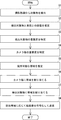
- FIG. 4 is a flowchart showing the operation of the transmission system according to the first embodiment.
- the transmission method according to the present embodiment is a transmission method in which images taken by a plurality of cameras mounted on a vehicle are transmitted via a network, and the available bandwidth of the network is determined.
- the band estimation step (step S11) for estimating and the camera band allocation step (step S12) for allocating the band for each camera according to the usable band and the importance for each camera are included.
- a transmission method capable of transmitting high-quality video suitable for remote control while suppressing loss and delay by allocating a band according to the importance of each camera.
- a transmission system can be provided.
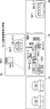
- FIG. 5 is a block diagram showing the configuration of the transmission system 1 according to the second embodiment.
- FIG. 6 is a flowchart showing the operation of the transmission system according to the second embodiment.
- the transmission system 1 encodes an image taken by a plurality of cameras 10A to 10D mounted on the vehicle into a moving image and transmits the image.
- the transmission system 1 includes an information processing device 100 that analyzes an image taken by the vehicle-mounted camera 10, manages a communication band based on the analysis result, and transmits video data via the network 30.
- the video data is projected onto the projection system 40 in the remote monitoring center and presented to the remote driver.
- a physically single information processing device 100 is configured to collectively process a plurality of cameras.
- the information processing device 100 (or 10, 200) of the present embodiment is a computer having a CPU (Central Processing Unit) 401, a RAM (Random access memory) 402, a ROM (Read Only Memory) 403, and the like. Is.
- the CPU 401 performs calculations and controls according to software stored in the RAM 402, the ROM 403, or the hard disk 404.
- the RAM 402 is used as a temporary storage area when the CPU 401 executes various processes.
- the hard disk 404 stores an operating system (OS), a registration program described later, and the like.
- OS operating system
- the display 405 is composed of a liquid crystal display and a graphic controller, and the display 405 displays objects such as images and icons, a GUI, and the like.
- the input unit 406 is a device for the user to give various instructions to the terminal device, and is composed of, for example, a mouse or a keyboard.
- the I / F (interface) unit 407 can control wireless LAN communication and wired LAN communication corresponding to standards such as IEEE 802.11a, and can control wireless LAN communication and wired LAN communication based on protocols such as TCP / IP via the same communication network and the Internet. Communicate with external devices.
- the system bus 408 controls data exchange with the CPU 401, RAM 402, ROM 403, hard disk 404, and the like.
- the control unit also functions as a functional calculation unit that executes each of the subdivided processes.
- the information processing apparatus 100 includes a band estimation unit 11, a camera band allocation unit 12, an object detection unit 101, an object state estimation unit 102, an object importance identification unit 108, and a camera importance identification unit. It includes 103, a region band allocation unit 104, an encoding unit 105, and a transmission unit 106.
- the transmission method according to the present embodiment will be described with reference to FIG.
- the flowchart of FIG. 6 shows a specific order of execution, but the order of execution may be different from the drawn form.
- the order of execution of two or more steps may be swapped with respect to the indicated order.
- the two or more steps shown consecutively in FIG. 6 may be performed simultaneously or partially simultaneously. Further, in some embodiments, one or more steps shown in FIG. 6 may be skipped or omitted.
- the object detection unit 101 detects an object of interest from images taken by a plurality of cameras, and determines the type of the object, the position of the object in the image, and the size of the object in the image. Acquire (step S1).
- the object state estimation unit 102 estimates the distance from the vehicle to the object from the detected object type, the position of the object in the image, and the size of the object in the image (step S2). ).
- the object importance specifying unit 108 manages the importance of the object type and the distance from the vehicle (vehicle-mounted camera) in association with each camera, and identifies the importance of the detected object based on the association (step S3). ..
- the camera importance specifying unit 103 identifies the importance of each camera from the total value of the importance of the detection objects detected for each camera (step S4).
- the band estimation unit 11 estimates the usable band (step S5). In the mobile phone network, the usable band constantly fluctuates, so the band estimation unit 11 estimates the usable band at a predetermined cycle (for example, every second).
- the camera band allocation unit 12 allocates a band for each camera according to the estimated usable band and the importance for each camera (step S6).
- the area band allocation unit 104 sets a band allocated to each camera (sometimes also called a camera band) and a band for transmitting a moving image of a region in which an object is detected according to the importance of the object. Allocate (step S7).
- the coding unit 105 encodes the moving image according to the allocated band. A moving image encoded by the transmission unit 106 is transmitted (step S8).
- the transmission method and transmission system 1 according to the present embodiment described above can transmit high-quality video suitable for remote control while suppressing loss and delay.
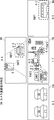
- FIG. 7 is a block diagram showing the configuration of the transmission system 1 according to the third embodiment.
- the same components as those in the second embodiment are designated by the same reference numerals as those in FIG. 5, and the description thereof will be omitted as appropriate.
- the present embodiment defines the operation of the second embodiment in more detail, and will be described below with reference to FIG. 6 which is a flowchart of the second embodiment.
- a plurality of information processing devices 100A to 100D are provided corresponding to each in-vehicle camera 10A to 10D.
- this system has a plurality of information processing devices 100A to 100D, and is configured to process images from a plurality of cameras in a distributed manner.
- the system includes a band estimation unit 11 that estimates the usable band, and a camera band allocation unit 12 that allocates a band to each camera based on the estimated usable band and the importance of the camera for each camera.
- the information processing device 10 is comprehensively provided.
- the vehicle state detection unit 23 that detects the vehicle state such as whether the vehicle is moving forward, backward, turning left, or turning right is totally added to the information processing device 10.
- the vehicle state detection unit 23 may estimate the vehicle state based on the images taken by each camera, or may detect the vehicle state through the in-vehicle network CAN (Controller Area Network), for example. Alternatively, the vehicle state detection unit 13 can determine where the gear of the vehicle is (drive, reverse, etc.) or a sensor.
- CAN Controller Area Network
- the system is configured to comprehensively include the information processing device 10, but the system is not limited to this, and the band estimation unit 11, the camera band allocation unit 12, and the vehicle state detection unit 13 also include the information processing devices 100A to 100A. It may be dispersed in 100D.
- FIG. 8 is a diagram illustrating an object detection process (step S1) and an object state estimation process (step S2) using an example of an image captured by each camera.
- an image may be displayed on a monitor viewed by the remote driver 3 or may be displayed on a monitor mounted on the vehicle 5.
- the image taken by the front in-vehicle camera 10A is shown as the front area image FA.
- the image taken by the rear vehicle-mounted camera 10B is shown as the rear area image BA.
- the image taken by the right vehicle-mounted camera 10C is shown as the right area image RA.
- the image taken by the left vehicle-mounted camera 10D is shown as the left area image LA.
- the object detection unit 101 detects an object such as a traffic light, a road sign, a person, a car, a bus, a truck, a motorcycle, and a bicycle with respect to the image data taken by each camera (step S1).
- the object detection unit 101 can detect an object by deep learning, and can utilize a model in which these images are learned in advance.
- three gaze regions surrounding the object are detected in the front region video FA. That is, an oncoming vehicle is detected in the front area gaze area FAF1, a person is detected in the front area gaze area FAF2, and a traffic light is detected in the front area gaze area FAF3.
- two gaze areas are detected in the rear region image BA. That is, a following vehicle is detected in the rear region gaze region BAF1, and a traffic light is detected in the rear region gaze region BAF2. Further, one gaze region is detected in the right region image RA. That is, a bus is detected in the right region gaze region BAF1. On the other hand, in the left region image LA, nothing is detected as a gaze region. The objects detected as these gaze areas should be gazed by the remote driver. Areas other than these gaze areas are called non-gaze areas and include areas that are not important to remote drivers (eg, helicopters flying in the air, shops and houses along the road, buildings, towers, etc.). ..
- the object state estimation unit 102 estimates the distance from the own vehicle (vehicle-mounted camera) to the detection target using the detection result by the object detection unit 101 (step S2). Since the in-vehicle camera is fixed to the vehicle and the range (angle of view) of the image is also fixed, the object state estimation unit 102 is the target based on the position and size (shape) in the image. The distance to an object can be estimated. Further, the object state estimation unit 102 may estimate the distance and the direction by deep learning. That is, the result of detecting the image of these objects, the distance of the car to the image, and the direction to the car may be learned in advance.
- the object state estimation units 102A to 102D use different learning models.
- Such a learning model may be stored in a storage unit inside the object state estimation units 102A to 102D, or stored in an external storage unit connected to the object state estimation units 102A to 102D via a network. You may be.
- the learning model constructed for each camera may be stored in the storage unit of the information processing device that collectively manages the system.
- the object state estimation units 102A to 102D estimate the distance from the in-vehicle cameras 10A to 10D to the object.
- the oncoming vehicle in the front region gaze area FAF1 is 8 m from the vehicle-mounted camera 10A
- the person in the front region gaze region FAF2 is 10 m from the vehicle-mounted camera 10A
- the traffic light in the front region gaze region FAF3 is. It is located 14 m from the in-vehicle camera 10A.
- the vehicle following the rear region gaze area BAF1 is 5 m from the vehicle-mounted camera 10D
- the traffic light in the rear region gaze region BAF2 is 15 m from the vehicle-mounted camera 10D.
- the bus in the right region gaze region BAF1 is 4 m from the vehicle-mounted camera 10C.
- the object name (BAF1 etc.), the distance (4 m), the allocated band (0.4 Mbps), etc. described in this figure may be displayed on the image displayed on the monitor or the like. , It is not necessary to display it.
- FIG. 9 is a diagram illustrating an object importance identification process using an example of an image taken by each camera.
- the image of FIG. 9 is the same as the image of FIG.
- FIG. 10 shows an example of a distance threshold table managed by the object importance specifying unit 108A.
- FIG. 11 shows an example of the object importance table managed by the object importance specifying unit 108A.
- the distance threshold table and the object importance table described above are for the case where the vehicle is moving forward, and these tables are used according to the state of the vehicle, such as when the vehicle is moving backward, turning left, or turning right. It may be different. That is, the object importance specifying unit 108 may change the distance threshold table and the object importance table according to the vehicle state detected by the vehicle state detecting unit 23.
- the object importance identification unit 108 includes not only the distance between the vehicle and the object estimated by the object state estimation unit 102, but also the direction of the object (that is, when the object is a vehicle, an oncoming vehicle and a preceding vehicle). , The intruding vehicle from the right side or the left side), the distance threshold table and the object importance table may be changed.
- the objects to be detected include fixed objects (for example, traffic lights) and moving objects (for example, cars, people).
- the object position prediction unit may output a prediction error or confidence or a probability distribution in addition to the object prediction position to enlarge or reduce the area size to acquire an area having an object with high probability.
- the importance is fixedly determined for an object within a distance determined for each type of object.
- a traffic light within 15 m in front of a vehicle is set to be important for a person within 10 m and a vehicle within 10 m.
- vehicles within 5 m behind the vehicle are set to be important.
- traffic lights within 10 m on the left and right sides of the vehicle, people within 5 m, and vehicles within 3 m are set to be important.
- an object closer to the threshold value is regarded as an important object with reference to the distance threshold table (FIG. 10), and the importance described in the object importance table (FIG. 11) is assigned to the important object. It is done by assigning. As shown in FIG. 9, since the oncoming vehicle in the front area gaze area FAF1 is 8 m, 0.4 is 10 m for the person in the front area gaze area FAF2, so 0.3 is the front area gaze area FAF3. Since the traffic light is 14m, 0.5 is assigned. Since the vehicle following the rear area gaze area BAF1 is 5 m, 0.3 is assigned, and since the traffic light in the rear area gaze area BAF2 is 15 m, 0 is assigned. Further, since the bus in the right region gaze region BAF1 is 4 m, 0.2 is assigned.
- FIG. 11 is a diagram illustrating a camera importance specifying process using an example of an image captured by each camera.
- FIG. 13 is an example of a non-gaze area importance table.
- the camera importance specifying unit 103A specifies the camera importance from the total value of the importance of all the detected objects captured by the camera and the importance of the non-gaze area (step S4).
- the non-gaze area refers to an area other than the gaze area surrounding the detection target in the entire screen captured by each camera. As shown in the non-gaze area importance table of FIG. 13, the importance of the non-gaze area differs depending on each camera (front, rear, left side, right side).
- the camera importance of the front area video FA is the sum of the importance of each detection object (oncoming vehicle, person, and traffic light) (that is, 0.4 + 0.3 + 0.5) and the importance of the non-gaze area in front (that is, 0.4 + 0.3 + 0.5). That is, by adding 0.5), it is calculated as 1.7.
- the camera importance of the rear region image BA is the sum of the importance of each detection object (following vehicle and traffic light) (that is, 0.3 + 0) and the importance of the rear non-gaze region (that is, 0. By adding 2), it is calculated as 0.5.
- the importance of the right region image RA is 0.5 by adding the importance of the right non-gaze region (0.3) to the total importance of the detection target (bus) (0.2). Calculated. Since there is no detection target, the importance of the left region image LA is calculated as 0.3 from the importance of the left non-gaze region.
- the band estimation unit 11 estimates the usable band (step S5).
- the usable band constantly fluctuates, so the band estimation unit 11 estimates the usable band at a predetermined cycle (for example, every second).
- the upstream usable band is estimated to be 6 Mbps.
- the camera band allocation unit 12 allocates a band for each camera according to the usable band (6 Mbps) and the importance of the camera for each camera described above (step S6).
- the importance of the front camera is 1.7
- the importance of the rear camera is 0.5
- the importance of the left camera is 0.3
- the importance of the right camera is 0.5.
- the allocated bandwidth of the front camera is calculated as 3.4 Mbps by multiplying the estimated uplink usable bandwidth (6 Mbps) by 1.7 / 3.0.
- the allocated band of the rear camera is calculated as 1.0 Mbps
- the allocated band of the left camera is 0.6 Mbps
- the allocated band of the right camera is 1.0 Mbps.
- the area band allocation unit 104A allocates a band for transmitting the detection target from the camera band according to the importance of the detection target (step S7).
- the area allocation band of each detection target is allocated in a proportional distribution according to the importance of the detection target. For example, in the front region FA, the region allocation band of the front region gaze region FAF1 with respect to the oncoming vehicle is calculated as 0.8 Mbps by multiplying 3.4 Mbps by 0.4 / 1.7.
- the area allocation band for a person in the front area gaze area FAF2 is calculated as 0.6 Mbps by multiplying 3.4 Mbps by 0.3 / 1.7.
- the area allocation band for the traffic light in the front area gaze area FAF3 is calculated as 1.0 Mbps by multiplying 3.4 Mbps by 0.5 / 1.7. Further, the area allocation band for the non-gaze area in the front area is calculated as 1.0 Mbps by multiplying 3.4 Mbps by 0.5 / 1.7.
- the area allocation band for the following vehicle in the rear region gaze region BAF1 is calculated as 0.6 Mbps by multiplying 1.0 Mbps by 0.3 / 0.5.
- the area allocated band for the non-gaze area in the rear area is calculated as 0.4 Mbps by multiplying 1.0 Mbps by 0.2 / 0.5.
- the area allocation band for the non-gaze area is calculated as 0.6 Mbps by multiplying 0.6 Mbps by 0.3 / 0.3.
- the region allocation band for the bus in the right region gaze region BAF1 is calculated as 0.4 Mbps by multiplying 1.0 Mbps by 0.2 / 0.5.
- the area allocation band for the non-gaze area in the right region is calculated as 0.6 Mbps by multiplying 1.0 Mbps by 0.3 / 0.5.
- the area band allocation unit 104 allocates the area band for all the detected objects.
- the transmission unit 106 encodes the moving image according to the allocated band and transmits the moving image (step S8).
- the transmission system according to the present embodiment described above can transmit high-quality video suitable for remote control while suppressing the occurrence of loss and delay.
- by reducing the allocated bandwidth for objects that cannot be important to the remote driver it is possible to suppress the occurrence of loss or delay in the mobile communication network.
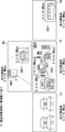
- FIG. 16 is a block diagram showing a configuration of a transmission system according to the fourth embodiment.
- FIG. 17 is a flowchart showing the operation of the transmission system according to the fourth embodiment.
- the transmission system 1 encodes an image taken by a plurality of cameras 10A to 10D mounted on the vehicle into a moving image and transmits the image.
- the transmission system 1 includes an information processing device 200 that analyzes an image taken by the in-vehicle camera 10, manages a communication band based on the analysis result, and transmits video data via the network 30.
- the video data is projected onto the projection system 40 in the remote monitoring center and presented to the remote driver.
- a physically single information processing device 200 is configured to collectively process a plurality of cameras. An example of the hardware configuration of the information processing device 200 is shown in FIG.
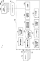
- the information processing apparatus 200 includes a band estimation unit 21, a camera band allocation unit 22, an object detection unit 201, an object state estimation unit 202, an object importance identification unit 208, and an object transmission band determination unit. It includes 211, a filter unit 203, a transmission area determination unit 204, an ROI (Region of Interest) area determination unit 207, an encoding unit 205, and a transmission unit 206.
- FIG. 17 shows a specific order of execution, but the order of execution may be different from the drawn form.
- the order of execution of two or more steps may be swapped with respect to the indicated order.
- the two or more steps shown in succession in FIG. 17 may be performed simultaneously or partially simultaneously. Further, in some embodiments, one or more steps shown in FIG. 17 may be skipped or omitted.
- the object detection unit 201 detects an object of interest from images taken by a plurality of cameras, and determines the type of the object, the position of the object in the image, and the size of the object in the image. Acquire (step S201).
- the object state estimation unit 202 estimates the distance from the vehicle to the object from the detected object type, the position of the object in the image, and the size of the object in the image (step). S202).
- the object importance specifying unit 208 specifies the importance of each camera based on the type of the object and the distance from the vehicle (step S203).
- the object importance specifying unit 208 refers to the distance threshold table (FIG. 10) described above, regards an object closer to the threshold as an important object, and describes the object importance table (FIG. 11) described above. Assign importance.
- the filter unit 203 filters out the objects that are not transmitted from the detected objects according to the distance of each object (step S204). By doing this, less important ones can be excluded. Further, as described above, an object capable of recognizing an object in a range that can be seen by a person with a visual acuity of 0.8 or more (for example, in the case of a road sign on a general road, the driver can recognize the sign at a distance of 10.66 m). Others can be excluded. As a result, the transmitted data can be reduced.
- the band estimation unit 21 estimates the usable band (step S205).
- the usable band constantly fluctuates, so the band estimation unit 21 estimates the usable band at a predetermined cycle (for example, every second).
- the object transmission band determination unit 211 determines the object transmission band according to the type of the object and the distance to the object (step S206).
- the object transmission band determination unit 211 obtains the bit rate conversion formula by referring to the bit rate conversion formula table shown in FIG. 19, substitutes the distance into the bit rate conversion formula, and determines the transmission bit rate of the object. In this way, the bit rate can be adjusted according to the difficulty of recognition depending on the distance and the object type.
- a and b of the bit rate conversion formula shown in FIG. 19 are arbitrary parameters, and x indicates the distance to the object.
- the ROI area determination unit 207 determines the ROI area for the object (step S207).
- FIG. 20 is a diagram illustrating an ROI area size determination process using an example of an image captured by each camera.
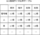
- Each ROI area size (FAF1', FAF2', FAF3', BAF1', RAF1' based on the ROI area size ratio table (FIG. 21) with respect to the size of the object considered to be important in the above-mentioned filter-out process. ) Is determined.
- the ROI area size of a moving body for example, a person or a car
- a fixed object for example, a traffic light
- the transmission area determination unit 204 determines the area and band of each layer according to the usable band, the transmission band of the target object, and the ROI area of the target object (step S208).
- the bit rate of the background area of each camera is set to the minimum bit rate of the background area, and the total bit rate of the background area is added to the band used.
- the objects having a short distance are added to the transmission object list, and the transmission bit rate of the object is added to the band used. This process is performed until there are no objects to be transmitted or the usable band falls below zero.
- the transmission band exceeds the limit usable band, the last added object (object o4) is deleted from the transmission object list.
- the remaining usable band is divided and assigned at the lowest bit rate ratio of the background area.
- the band of the background area can be increased, and the image of the background area of the highest quality possible can be transmitted to the remote driver while suppressing loss and delay.
- the coding unit 105 encodes the moving image according to the allocated band.
- the transmission unit 106 transmits the encoded moving image (step S208).
- the transmission system 1 can transmit high-quality video optimized for remote control while suppressing loss and delay. Further, according to the present embodiment, even if the object is a moving object, the ROI area can be expanded correspondingly, and even higher quality video can be transmitted. Further, in the present embodiment, by providing the object transmission band determination unit, the bit rate can be determined according to the difficulty of recognition depending on the distance and the object type.
- the system control device includes a band estimation unit that estimates the usable band, which is the band that can be used in the network, in order to transmit images taken by a plurality of cameras mounted on the vehicle, and the usable band and each camera. It is provided with a camera band allocation unit that allocates a band for each camera according to the importance of.
- Non-temporary computer-readable media include various types of tangible storage media.
- Examples of non-temporary computer-readable media include magnetic recording media, magneto-optical recording media (eg, magneto-optical disks), CD-ROMs (Read Only Memory), CD-Rs, CD-R / Ws, and semiconductor memories.
- the magnetic recording medium may be, for example, a flexible disk, a magnetic tape, or a hard disk drive.
- the semiconductor memory may be, for example, a mask ROM, a PROM (Programmable ROM), an EPROM (Erasable PROM), a flash ROM, or a RAM (Random Access Memory).
- the program may also be supplied to the computer by various types of temporary computer readable media.
- Examples of temporary computer-readable media include electrical, optical, and electromagnetic waves.
- the temporary computer-readable medium can supply the program to the computer via a wired communication path such as an electric wire and an optical fiber, or a wireless communication path.
- Appendix 1 It is a transmission method that transmits images taken by multiple cameras mounted on a vehicle via a network.
- a band estimation step for estimating the usable band which is the band that can be used in the network, and
- a camera band allocation step that allocates a band for each camera according to the available band and the importance of each camera, Sending method, including.
- (Appendix 2) It further includes the step of identifying the importance of each camera.
- An object state estimation step for estimating the distance from the vehicle to the object from the detected type of the object, the position of the object in the image, and the size of the object in the image.
- An object importance identification step for specifying the importance of an object based on the type of the object and the distance from the vehicle, and From the total value of the importance of the object detected for each camera, the camera importance specifying step for specifying the importance for each camera and the camera importance specifying step.
- the transmission method according to Appendix 1 which comprises. (Appendix 3) An area band allocation step for allocating a band for transmitting a moving image of a region in which the detected object is captured according to the band allocated for each camera and the importance of the object.
- the transmission method according to Appendix 2 further comprising.
- the object importance identification step is based on a distance threshold table showing the threshold value of the distance between the vehicle and each object and an object importance table showing the importance by associating the camera with each object.
- the transmission method described in Appendix 2 for specifying the importance. (Appendix 5) It further includes a vehicle condition detection step to detect the vehicle condition.
- the transmission method according to Appendix 4, wherein in the object importance specifying step, the distance threshold table and the object importance table are changed according to the vehicle state.
- the orientation of the object is estimated and the object is estimated.
- Appendix 10 The transmission method according to any one of Appendix 2 to 9, further comprising a filtering step of filtering out an object that is not transmitted from the detected moving image according to the distance to the object.
- Appendix 11 It is a transmission system that transmits images taken by multiple cameras mounted on a vehicle via a network.
- a band estimation unit that estimates the usable band, which is the band that can be used in the network, and
- a camera band allocation unit that allocates a band for each camera according to the available band and the importance of each camera, A transmission system.
- An object detection unit that detects an object of interest from images taken by the plurality of cameras and acquires the type of the object, the position of the object in the image, and the size of the object in the image.
- Object state estimation that estimates the distance from the vehicle to the object from the type of the detected object, the position of the object in the image, and the size of the object in the image.
- Department and An object importance specifying unit that specifies the importance of each camera based on the object type and the distance from the vehicle.
- the transmission system according to Appendix 12 further comprising an area band allocation unit that allocates a band for transmitting a moving image of the detected object area according to the importance of the camera band and the detection object.
- the object importance identification unit determines the importance based on the distance threshold table showing the threshold of the distance between the vehicle and each object and the object importance table showing the importance by associating the camera with each object.
- (Appendix 16) The object state estimation unit estimates the orientation of the object and The transmission system according to Appendix 14, wherein the object importance specifying unit changes the object importance table according to the orientation of the object.
- (Appendix 17) The transmission system according to Appendix 12, wherein the object state estimation unit estimates a distance by using a learning model different for each camera.
- (Appendix 18) The transmission system according to any one of Supplementary note 12 to 17, further comprising an ROI area determination unit that determines an ROI area of the object according to the type of the object and the size of the object.
- (Appendix 19) The transmission system according to Appendix 18, wherein the ROI region size when the detected object is a moving object is set to be larger than the ROI region size when the detected object is a fixed object.
- Appendix 20 The transmission system according to any one of Appendix 12 to 19, further comprising a filter unit that filters out an object that is not transmitted from the detected moving image according to the distance to the object.
- Appendix 21 A band estimation unit that estimates the usable band, which is the band that can be used in the network, to transmit images taken by multiple cameras mounted on the vehicle.
- a camera band allocation unit that allocates a band for each camera according to the available band and the importance of each camera, A system control unit.
- Appendix 22 To determine the importance of each camera An object detection unit that detects an object of interest from images taken by the plurality of cameras and acquires the type of the object, the position of the object in the image, and the size of the object in the image.
- Object state estimation unit that estimates the distance from the vehicle to the object from the type of the detected object, the position of the object in the image, and the size of the object in the image.
- An object importance specifying unit that specifies the importance of each camera based on the type of the object and the distance from the vehicle.
- the system control device according to Appendix 21, further comprising a camera importance specifying unit that specifies the importance of each camera from the total value of the importance of the object detected for each camera.
- a supplementary note further comprising an area band allocation unit that allocates a band for transmitting a moving image of a region in which the detected object is photographed according to the band allocated for each camera and the importance of the object. 22.
- the system control device is configured to estimate the distance from the vehicle to the object from the type of the detected object, the position of the object in the image, and the size of the object in the image.
- the object importance identification unit determines the importance based on the distance threshold table showing the threshold of the distance between the vehicle and each object and the object importance table showing the importance by associating the camera with each object.
- (Appendix 25) Further equipped with a vehicle condition detection unit that detects the vehicle condition, The system control device according to Appendix 24, wherein the object importance specifying unit changes the distance threshold table and the object importance table according to the vehicle state.
- Transmission system 3 Remote driver 5 Vehicle 10 In-vehicle camera 11 Band estimation unit 12 Camera band allocation unit 13 Vehicle condition detection unit 21 Band estimation unit 22 Camera band allocation unit 30 Network 40 Projection system 100 Information processing device 101 Object detection unit 102 Object state estimation unit 103 Camera importance identification unit 104 Area band allocation unit 105 Coding unit 106 Transmission unit 108 Object importance identification unit 201 Object detection unit 202 Object state estimation unit 203 Filter unit 204 Transmission area determination unit 205 Encoding unit 206 Transmission unit 207 ROI area determination unit 208 Object importance identification unit 211 Object transmission band determination unit 400 Ground monitoring remote control device FA Front area BA Rear area RA Right area LA Left area
Landscapes
- Engineering & Computer Science (AREA)
- Multimedia (AREA)
- Signal Processing (AREA)
- Physics & Mathematics (AREA)
- General Physics & Mathematics (AREA)
- Theoretical Computer Science (AREA)
- Computer Vision & Pattern Recognition (AREA)
- Traffic Control Systems (AREA)
- Closed-Circuit Television Systems (AREA)
Abstract
L'invention concerne un procédé de transmission, un système de transmission et un dispositif de commande de système pouvant transmettre une vidéo de haute qualité appropriée pour un fonctionnement à distance, tout en supprimant la perte et le retard. Le procédé de transmission consiste à transmettre des images prises par une pluralité de caméras (10) montées sur un véhicule (5) par l'intermédiaire d'un réseau (30) et comprend : une étape d'estimation de bande passante (S11) consistant à estimer la bande passante disponible du réseau ; une étape d'attribution de bande passante de caméra (S12) consistant à attribuer une bande passante pour chaque caméra en fonction de la bande passante disponible et de l'importance de chaque caméra.
Priority Applications (3)
| Application Number | Priority Date | Filing Date | Title |
|---|---|---|---|
| US17/765,487 US20220368860A1 (en) | 2019-10-07 | 2019-10-07 | Transmission method, transmission system, and system control device |
| PCT/JP2019/039446 WO2021070214A1 (fr) | 2019-10-07 | 2019-10-07 | Procédé et système de transmission et dispositif de commande de système |
| JP2021550947A JPWO2021070214A1 (fr) | 2019-10-07 | 2019-10-07 |
Applications Claiming Priority (1)
| Application Number | Priority Date | Filing Date | Title |
|---|---|---|---|
| PCT/JP2019/039446 WO2021070214A1 (fr) | 2019-10-07 | 2019-10-07 | Procédé et système de transmission et dispositif de commande de système |
Publications (1)
| Publication Number | Publication Date |
|---|---|
| WO2021070214A1 true WO2021070214A1 (fr) | 2021-04-15 |
Family
ID=75437018
Family Applications (1)
| Application Number | Title | Priority Date | Filing Date |
|---|---|---|---|
| PCT/JP2019/039446 WO2021070214A1 (fr) | 2019-10-07 | 2019-10-07 | Procédé et système de transmission et dispositif de commande de système |
Country Status (3)
| Country | Link |
|---|---|
| US (1) | US20220368860A1 (fr) |
| JP (1) | JPWO2021070214A1 (fr) |
| WO (1) | WO2021070214A1 (fr) |
Cited By (2)
| Publication number | Priority date | Publication date | Assignee | Title |
|---|---|---|---|---|
| US20230010078A1 (en) * | 2021-07-12 | 2023-01-12 | Avago Technologies International Sales Pte. Limited | Object or region of interest video processing system and method |
| WO2023074394A1 (fr) * | 2021-10-29 | 2023-05-04 | 住友電気工業株式会社 | Dispositif embarqué, dispositif de bord de route, procédé de commande et programme informatique |
Families Citing this family (1)
| Publication number | Priority date | Publication date | Assignee | Title |
|---|---|---|---|---|
| US11936700B1 (en) * | 2023-02-16 | 2024-03-19 | GM Global Technology Operations LLC | Vehicle video streaming system and method |
Citations (5)
| Publication number | Priority date | Publication date | Assignee | Title |
|---|---|---|---|---|
| US20090190653A1 (en) * | 2008-01-30 | 2009-07-30 | Sungha Seo | Apparatus and method for adjusting bit rate in security device connected to external storage |
| JP2011040797A (ja) * | 2007-11-05 | 2011-02-24 | Nec Corp | コンテンツ送信方法及びその装置並びにその制御プログラム |
| JP2016134816A (ja) * | 2015-01-21 | 2016-07-25 | 株式会社日立製作所 | 画像調整方法、サーバ及び動画撮影システム |
| JP2018093401A (ja) * | 2016-12-05 | 2018-06-14 | キヤノンイメージングシステムズ株式会社 | 映像監視装置、映像監視方法および映像監視システム |
| JP2018142921A (ja) * | 2017-02-28 | 2018-09-13 | パナソニックIpマネジメント株式会社 | 自動運転制御装置、自動運転制御方法、自動運転制御プログラム、自動運転車両、遠隔制御装置、遠隔制御方法、及び遠隔制御プログラム |
Family Cites Families (9)
| Publication number | Priority date | Publication date | Assignee | Title |
|---|---|---|---|---|
| WO2007032140A1 (fr) * | 2005-09-15 | 2007-03-22 | Sharp Kabushiki Kaisha | Appareil de transfert d'image et dispositif d'affichage utilisant celui-ci |
| US8441535B2 (en) * | 2008-03-05 | 2013-05-14 | Omnivision Technologies, Inc. | System and method for independent image sensor parameter control in regions of interest |
| US20140002651A1 (en) * | 2012-06-30 | 2014-01-02 | James Plante | Vehicle Event Recorder Systems |
| CN107004361B (zh) * | 2014-12-09 | 2020-03-27 | 三菱电机株式会社 | 碰撞风险计算装置、碰撞风险显示装置以及车体控制装置 |
| US10367869B2 (en) * | 2014-12-30 | 2019-07-30 | Ford Global Technologies, Llc | Remote vehicle control and operation |
| JP6793193B2 (ja) * | 2016-06-29 | 2020-12-02 | 京セラ株式会社 | 物体検出表示装置、移動体及び物体検出表示方法 |
| CN109564723B (zh) * | 2016-08-26 | 2022-11-08 | 索尼公司 | 移动体控制装置、移动体控制方法以及移动体 |
| US10779194B2 (en) * | 2017-03-27 | 2020-09-15 | Qualcomm Incorporated | Preferred path network scheduling in multi-modem setup |
| JP7139717B2 (ja) * | 2018-06-26 | 2022-09-21 | 株式会社デンソー | 車両用通信装置、車両用通信方法、及び制御プログラム |
-
2019
- 2019-10-07 WO PCT/JP2019/039446 patent/WO2021070214A1/fr active Application Filing
- 2019-10-07 JP JP2021550947A patent/JPWO2021070214A1/ja active Pending
- 2019-10-07 US US17/765,487 patent/US20220368860A1/en active Pending
Patent Citations (5)
| Publication number | Priority date | Publication date | Assignee | Title |
|---|---|---|---|---|
| JP2011040797A (ja) * | 2007-11-05 | 2011-02-24 | Nec Corp | コンテンツ送信方法及びその装置並びにその制御プログラム |
| US20090190653A1 (en) * | 2008-01-30 | 2009-07-30 | Sungha Seo | Apparatus and method for adjusting bit rate in security device connected to external storage |
| JP2016134816A (ja) * | 2015-01-21 | 2016-07-25 | 株式会社日立製作所 | 画像調整方法、サーバ及び動画撮影システム |
| JP2018093401A (ja) * | 2016-12-05 | 2018-06-14 | キヤノンイメージングシステムズ株式会社 | 映像監視装置、映像監視方法および映像監視システム |
| JP2018142921A (ja) * | 2017-02-28 | 2018-09-13 | パナソニックIpマネジメント株式会社 | 自動運転制御装置、自動運転制御方法、自動運転制御プログラム、自動運転車両、遠隔制御装置、遠隔制御方法、及び遠隔制御プログラム |
Cited By (3)
| Publication number | Priority date | Publication date | Assignee | Title |
|---|---|---|---|---|
| US20230010078A1 (en) * | 2021-07-12 | 2023-01-12 | Avago Technologies International Sales Pte. Limited | Object or region of interest video processing system and method |
| US11985389B2 (en) * | 2021-07-12 | 2024-05-14 | Avago Technologies International Sales Pte. Limited | Object or region of interest video processing system and method |
| WO2023074394A1 (fr) * | 2021-10-29 | 2023-05-04 | 住友電気工業株式会社 | Dispositif embarqué, dispositif de bord de route, procédé de commande et programme informatique |
Also Published As
| Publication number | Publication date |
|---|---|
| US20220368860A1 (en) | 2022-11-17 |
| JPWO2021070214A1 (fr) | 2021-04-15 |
Similar Documents
| Publication | Publication Date | Title |
|---|---|---|
| WO2021070214A1 (fr) | Procédé et système de transmission et dispositif de commande de système | |
| US10877485B1 (en) | Handling intersection navigation without traffic lights using computer vision | |
| US11158056B2 (en) | Surround camera system with seamless stitching for arbitrary viewpoint selection | |
| US11112791B2 (en) | Selective compression of image data during teleoperation of a vehicle | |
| US10744936B1 (en) | Using camera data to automatically change the tint of transparent materials | |
| US11263769B2 (en) | Image processing device, image processing method, and image processing system | |
| US20220180483A1 (en) | Image processing device, image processing method, and program | |
| JP2018514011A (ja) | 環境シーン状態検出 | |
| US11970156B1 (en) | Parking assistance using a stereo camera and an added light source | |
| US20200213560A1 (en) | System and method for a dynamic human machine interface for video conferencing in a vehicle | |
| KR20200043391A (ko) | 화상 블러 보정을 위한 화상 처리, 화상 처리 방법 및 프로그램 | |
| JP2021057724A (ja) | 監視センタ、及び支援方法 | |
| US11586843B1 (en) | Generating training data for speed bump detection | |
| CN111510735B (zh) | 弱网环境下多路视频的编码传输方法、装置及无人车辆 | |
| EP4156729A1 (fr) | Calcul de carte de grille d'occupation, détection complémentaire v2x et coordination de transmission de données de perception coopérative dans des réseaux sans fil | |
| TW201617252A (zh) | 自動追蹤防撞警示系統及其方法 | |
| CN110264651A (zh) | 列车站台行人越线监测方法、装置、终端及存储介质 | |
| CN112558755A (zh) | 人机接口的能量和/或资源管理的方法和系统 | |
| JP7310126B2 (ja) | 情報解析装置、情報解析方法、情報解析システム、及びコンピュータプログラム | |
| WO2019111529A1 (fr) | Dispositif et procédé de traitement d'image | |
| JP2023529575A (ja) | 自律車両遠隔操作のための画質強化 | |
| WO2021199350A1 (fr) | Système, dispositif, procédé dee surveillance à distance, et support lisible par ordinateur | |
| WO2021199351A1 (fr) | Système de surveillance à distance, appareil de surveillance à distance, et procédé | |
| JP7143263B2 (ja) | 符号化パラメータを用いて対象識別位置を決定する対象識別方法、装置及びプログラム | |
| Sakaushi et al. | Edge-centric video surveillance system based on event-driven rate adaptation for 24-hour monitoring |
Legal Events
| Date | Code | Title | Description |
|---|---|---|---|
| 121 | Ep: the epo has been informed by wipo that ep was designated in this application |
Ref document number: 19948456 Country of ref document: EP Kind code of ref document: A1 |
|
| ENP | Entry into the national phase |
Ref document number: 2021550947 Country of ref document: JP Kind code of ref document: A |
|
| NENP | Non-entry into the national phase |
Ref country code: DE |
|
| 122 | Ep: pct application non-entry in european phase |
Ref document number: 19948456 Country of ref document: EP Kind code of ref document: A1 |