WO2021070214A1 - 送信方法、送信システム及びシステム制御装置 - Google Patents
送信方法、送信システム及びシステム制御装置 Download PDFInfo
- Publication number
- WO2021070214A1 WO2021070214A1 PCT/JP2019/039446 JP2019039446W WO2021070214A1 WO 2021070214 A1 WO2021070214 A1 WO 2021070214A1 JP 2019039446 W JP2019039446 W JP 2019039446W WO 2021070214 A1 WO2021070214 A1 WO 2021070214A1
- Authority
- WO
- WIPO (PCT)
- Prior art keywords
- importance
- camera
- band
- vehicle
- image
- Prior art date
Links
Images


Classifications
-
- H—ELECTRICITY
- H04—ELECTRIC COMMUNICATION TECHNIQUE
- H04N—PICTORIAL COMMUNICATION, e.g. TELEVISION
- H04N7/00—Television systems
- H04N7/18—Closed-circuit television [CCTV] systems, i.e. systems in which the video signal is not broadcast
- H04N7/181—Closed-circuit television [CCTV] systems, i.e. systems in which the video signal is not broadcast for receiving images from a plurality of remote sources
-
- G—PHYSICS
- G06—COMPUTING; CALCULATING OR COUNTING
- G06T—IMAGE DATA PROCESSING OR GENERATION, IN GENERAL
- G06T7/00—Image analysis
-
- G—PHYSICS
- G06—COMPUTING; CALCULATING OR COUNTING
- G06V—IMAGE OR VIDEO RECOGNITION OR UNDERSTANDING
- G06V20/00—Scenes; Scene-specific elements
- G06V20/50—Context or environment of the image
- G06V20/56—Context or environment of the image exterior to a vehicle by using sensors mounted on the vehicle
-
- H—ELECTRICITY
- H04—ELECTRIC COMMUNICATION TECHNIQUE
- H04N—PICTORIAL COMMUNICATION, e.g. TELEVISION
- H04N21/00—Selective content distribution, e.g. interactive television or video on demand [VOD]
- H04N21/20—Servers specifically adapted for the distribution of content, e.g. VOD servers; Operations thereof
- H04N21/23—Processing of content or additional data; Elementary server operations; Server middleware
- H04N21/24—Monitoring of processes or resources, e.g. monitoring of server load, available bandwidth, upstream requests
-
- G—PHYSICS
- G06—COMPUTING; CALCULATING OR COUNTING
- G06V—IMAGE OR VIDEO RECOGNITION OR UNDERSTANDING
- G06V20/00—Scenes; Scene-specific elements
- G06V20/50—Context or environment of the image
- G06V20/56—Context or environment of the image exterior to a vehicle by using sensors mounted on the vehicle
- G06V20/58—Recognition of moving objects or obstacles, e.g. vehicles or pedestrians; Recognition of traffic objects, e.g. traffic signs, traffic lights or roads
Definitions
- This disclosure relates to a transmission method, a transmission system, and a system control device.
- Non-Patent Document 1 discloses a technique for lowering the image quality of a region not viewed by a viewer and improving the image quality of a visually prominent region that a human naturally gazes at as an important region.
- As a method of selecting an important region there is a saliency map calculation algorithm that calculates from the brightness, the hue component, and the direction of the edge. This makes it possible to deliver high QoE video even in a limited band.
- the present invention has been made to solve such a problem, and is a transmission method, a transmission system, and a system control device capable of transmitting high-quality video suitable for remote control while suppressing loss and delay.
- the purpose is to provide.
- the transmission method according to the first aspect of the present disclosure is a transmission method of transmitting images taken by a plurality of cameras mounted on a vehicle via a network.
- a band estimation step for estimating the usable band which is the band that can be used in the network
- a camera band allocation step that allocates a band for each camera according to the available band and the importance of each camera, including.
- the transmission system is It is a transmission system that transmits images taken by multiple cameras mounted on a vehicle via a network.
- a bandwidth estimation unit that estimates the available bandwidth in the network
- a camera band allocation unit that allocates a band for each camera according to the available band and the importance of each camera, To be equipped.
- the system control device is A band estimation unit that estimates the usable band, which is the band that can be used in the network, in order to transmit images taken by multiple cameras mounted on the vehicle.
- a camera band allocation unit that allocates a band for each camera according to the available band and the importance of each camera, To be equipped.
- FIG. It is the schematic explaining the outline of the remote monitoring operation system. It is a figure explaining the bandwidth shortage in the remote monitoring system via a mobile network. It is a block diagram which shows the structure in the transmission system which concerns on Embodiment 1.
- FIG. It is a flowchart which shows the operation of the transmission system which concerns on Embodiment 1.
- FIG. It is a block diagram which shows the structure in the transmission system which concerns on Embodiment 2.
- FIG. It is a flowchart which shows the operation of the transmission system which concerns on Embodiment 2.
- FIG. It is a figure explaining the object detection process and the object state estimation process using an example of the image taken by each camera.
- An example of a bit rate conversion expression table is shown.
- An example of the ROI area size ratio table is shown.
- the remote monitoring driving system remotely controls the vehicle 5 that does not require a driver from the remote monitoring center.
- images taken by a plurality of in-vehicle cameras 10A to 10D mounted on the vehicle 5 are transmitted to the ground monitoring control device 400 via a wireless communication network and the Internet.
- the remote driver 3 remotely controls the received video while viewing it on the monitor.
- the remote control device mounted on the vehicle 5 performs bidirectional communication with the ground monitoring remote control device 400 by using a communication method (for example, LTE, 5G) using a mobile phone network.
- the remote-controlled driving system may be switched to remote control or automatic control when a vehicle under remote monitoring is running and a danger of the vehicle is detected. That is, the vehicle driven by a person may be temporarily switched to such control, and the vehicle may have a driver.
- the in-vehicle camera 10A photographs the front of the vehicle
- the in-vehicle camera 10B photographs the rear of the vehicle
- the in-vehicle camera 10C photographs the right side of the vehicle
- the in-vehicle camera 10D photographs the left side of the vehicle.
- the number of in-vehicle cameras is not limited to this, and may be 5 or more. Further, the performance of each camera is basically the same, but may be slightly different.
- An ordinary driver such as a taxi is required to have a second-class license, which requires that he / she can recognize an object (also called an object) within a range that a person with a visual acuity of 0.8 or more can see.
- the image provided to the remote driver can also recognize the object in the range where a person with a visual acuity of 0.8 or more can see (for example, in the case of a road sign on a general road, the driver signs the sign at a distance of 10.66 m). It is desirable that it can be recognized.
- the remote driver needs to visually recognize not only the object but also the peripheral information of the object, and it is desirable to transmit such peripheral information to the remote driver as a relatively high-quality image.
- FIG. 2 is a diagram illustrating a bandwidth shortage in a remote monitoring system via a mobile network.
- each image taken by each of the cameras 10A to 10D is uniformly transmitted via the mobile phone network.
- the usable band (hereinafter, also referred to as the usable band) may fluctuate, so that the image quality may deteriorate due to the lack of band.
- video is transmitted at a bit rate higher than the communication band, loss or delay may occur in the communication network.
- the present invention solves such a problem.
- the present invention has a function of determining an image area to be watched by a remote driver from an image taken by an in-vehicle camera, a function of determining an important camera from a plurality of cameras, and a camera image. It has a function to automatically extract areas important for remote operation.
- the in-vehicle computer resources are limited in this system, it may be necessary to cooperate with a computer on the remote driver side, which has abundant computer resources.
- the distance between the detection object and the vehicle is estimated, the importance of each object is determined, and the area of the object having a high importance is preferentially refined to the remote driver side.
- the importance is calculated from the type of object (object) and the distance from the vehicle to the object.
- the actual distance and orientation with respect to the position and size in the image are learned in advance for each object type, and the distance to the object and the orientation of the object are estimated from the image when the system is implemented.
- a large amount of usable bandwidth is allocated to cameras with a high total importance value of all objects in the image captured by each camera. Since the objects that need to be watched differ for each camera and the priorities of the cameras also differ, the importance to the distance and orientation is set for each object type for each camera.
- the method implemented by this system includes pre-work (learning) and the process at the time of system implementation.
- the distance from the car is measured and learned with respect to the position and size in the image taken by each camera, and the importance of the distance from the car is set for each type of camera and object.
- the object in the image taken by each camera is recognized, and the position, size, and type of the object in the image are acquired.
- the importance to the distance and orientation from the vehicle is specified for each preset camera and object type, and the importance is specified from the position, size, and type of the recognized object.
- the total importance value of the objects photographed by each camera is calculated, and the band is allocated to each camera according to the importance from the usable band.
- the band is allocated to the area where the object exists in each camera and the band is allocated to the area according to the importance of the object. By doing so, it is possible to increase the probability that the remote driver can recognize an object that affects driving even in a limited band.
- FIG. 3 is a block diagram showing a configuration in the transmission system according to the first embodiment.
- the transmission system according to the first embodiment is an information processing device 100 including a band estimation unit 11 and a camera band allocation unit 12 (the hardware configuration will be described later with reference to FIG. 26).
- the transmission system is a transmission system that transmits images taken by a plurality of cameras mounted on a vehicle via a network, and is a band estimation unit 11 that estimates the usable band of the network, and the usable band and the camera.
- a camera band allocation unit 12 for allocating a band for each camera according to the importance of each camera is provided.
- the information processing device 100 may be called a system control device.
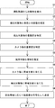
- FIG. 4 is a flowchart showing the operation of the transmission system according to the first embodiment.
- the transmission method according to the present embodiment is a transmission method in which images taken by a plurality of cameras mounted on a vehicle are transmitted via a network, and the available bandwidth of the network is determined.
- the band estimation step (step S11) for estimating and the camera band allocation step (step S12) for allocating the band for each camera according to the usable band and the importance for each camera are included.
- a transmission method capable of transmitting high-quality video suitable for remote control while suppressing loss and delay by allocating a band according to the importance of each camera.
- a transmission system can be provided.
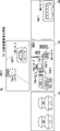
- FIG. 5 is a block diagram showing the configuration of the transmission system 1 according to the second embodiment.
- FIG. 6 is a flowchart showing the operation of the transmission system according to the second embodiment.
- the transmission system 1 encodes an image taken by a plurality of cameras 10A to 10D mounted on the vehicle into a moving image and transmits the image.
- the transmission system 1 includes an information processing device 100 that analyzes an image taken by the vehicle-mounted camera 10, manages a communication band based on the analysis result, and transmits video data via the network 30.
- the video data is projected onto the projection system 40 in the remote monitoring center and presented to the remote driver.
- a physically single information processing device 100 is configured to collectively process a plurality of cameras.
- the information processing device 100 (or 10, 200) of the present embodiment is a computer having a CPU (Central Processing Unit) 401, a RAM (Random access memory) 402, a ROM (Read Only Memory) 403, and the like. Is.
- the CPU 401 performs calculations and controls according to software stored in the RAM 402, the ROM 403, or the hard disk 404.
- the RAM 402 is used as a temporary storage area when the CPU 401 executes various processes.
- the hard disk 404 stores an operating system (OS), a registration program described later, and the like.
- OS operating system
- the display 405 is composed of a liquid crystal display and a graphic controller, and the display 405 displays objects such as images and icons, a GUI, and the like.
- the input unit 406 is a device for the user to give various instructions to the terminal device, and is composed of, for example, a mouse or a keyboard.
- the I / F (interface) unit 407 can control wireless LAN communication and wired LAN communication corresponding to standards such as IEEE 802.11a, and can control wireless LAN communication and wired LAN communication based on protocols such as TCP / IP via the same communication network and the Internet. Communicate with external devices.
- the system bus 408 controls data exchange with the CPU 401, RAM 402, ROM 403, hard disk 404, and the like.
- the control unit also functions as a functional calculation unit that executes each of the subdivided processes.
- the information processing apparatus 100 includes a band estimation unit 11, a camera band allocation unit 12, an object detection unit 101, an object state estimation unit 102, an object importance identification unit 108, and a camera importance identification unit. It includes 103, a region band allocation unit 104, an encoding unit 105, and a transmission unit 106.
- the transmission method according to the present embodiment will be described with reference to FIG.
- the flowchart of FIG. 6 shows a specific order of execution, but the order of execution may be different from the drawn form.
- the order of execution of two or more steps may be swapped with respect to the indicated order.
- the two or more steps shown consecutively in FIG. 6 may be performed simultaneously or partially simultaneously. Further, in some embodiments, one or more steps shown in FIG. 6 may be skipped or omitted.
- the object detection unit 101 detects an object of interest from images taken by a plurality of cameras, and determines the type of the object, the position of the object in the image, and the size of the object in the image. Acquire (step S1).
- the object state estimation unit 102 estimates the distance from the vehicle to the object from the detected object type, the position of the object in the image, and the size of the object in the image (step S2). ).
- the object importance specifying unit 108 manages the importance of the object type and the distance from the vehicle (vehicle-mounted camera) in association with each camera, and identifies the importance of the detected object based on the association (step S3). ..
- the camera importance specifying unit 103 identifies the importance of each camera from the total value of the importance of the detection objects detected for each camera (step S4).
- the band estimation unit 11 estimates the usable band (step S5). In the mobile phone network, the usable band constantly fluctuates, so the band estimation unit 11 estimates the usable band at a predetermined cycle (for example, every second).
- the camera band allocation unit 12 allocates a band for each camera according to the estimated usable band and the importance for each camera (step S6).
- the area band allocation unit 104 sets a band allocated to each camera (sometimes also called a camera band) and a band for transmitting a moving image of a region in which an object is detected according to the importance of the object. Allocate (step S7).
- the coding unit 105 encodes the moving image according to the allocated band. A moving image encoded by the transmission unit 106 is transmitted (step S8).
- the transmission method and transmission system 1 according to the present embodiment described above can transmit high-quality video suitable for remote control while suppressing loss and delay.
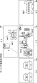
- FIG. 7 is a block diagram showing the configuration of the transmission system 1 according to the third embodiment.
- the same components as those in the second embodiment are designated by the same reference numerals as those in FIG. 5, and the description thereof will be omitted as appropriate.
- the present embodiment defines the operation of the second embodiment in more detail, and will be described below with reference to FIG. 6 which is a flowchart of the second embodiment.
- a plurality of information processing devices 100A to 100D are provided corresponding to each in-vehicle camera 10A to 10D.
- this system has a plurality of information processing devices 100A to 100D, and is configured to process images from a plurality of cameras in a distributed manner.
- the system includes a band estimation unit 11 that estimates the usable band, and a camera band allocation unit 12 that allocates a band to each camera based on the estimated usable band and the importance of the camera for each camera.
- the information processing device 10 is comprehensively provided.
- the vehicle state detection unit 23 that detects the vehicle state such as whether the vehicle is moving forward, backward, turning left, or turning right is totally added to the information processing device 10.
- the vehicle state detection unit 23 may estimate the vehicle state based on the images taken by each camera, or may detect the vehicle state through the in-vehicle network CAN (Controller Area Network), for example. Alternatively, the vehicle state detection unit 13 can determine where the gear of the vehicle is (drive, reverse, etc.) or a sensor.
- CAN Controller Area Network
- the system is configured to comprehensively include the information processing device 10, but the system is not limited to this, and the band estimation unit 11, the camera band allocation unit 12, and the vehicle state detection unit 13 also include the information processing devices 100A to 100A. It may be dispersed in 100D.
- FIG. 8 is a diagram illustrating an object detection process (step S1) and an object state estimation process (step S2) using an example of an image captured by each camera.
- an image may be displayed on a monitor viewed by the remote driver 3 or may be displayed on a monitor mounted on the vehicle 5.
- the image taken by the front in-vehicle camera 10A is shown as the front area image FA.
- the image taken by the rear vehicle-mounted camera 10B is shown as the rear area image BA.
- the image taken by the right vehicle-mounted camera 10C is shown as the right area image RA.
- the image taken by the left vehicle-mounted camera 10D is shown as the left area image LA.
- the object detection unit 101 detects an object such as a traffic light, a road sign, a person, a car, a bus, a truck, a motorcycle, and a bicycle with respect to the image data taken by each camera (step S1).
- the object detection unit 101 can detect an object by deep learning, and can utilize a model in which these images are learned in advance.
- three gaze regions surrounding the object are detected in the front region video FA. That is, an oncoming vehicle is detected in the front area gaze area FAF1, a person is detected in the front area gaze area FAF2, and a traffic light is detected in the front area gaze area FAF3.
- two gaze areas are detected in the rear region image BA. That is, a following vehicle is detected in the rear region gaze region BAF1, and a traffic light is detected in the rear region gaze region BAF2. Further, one gaze region is detected in the right region image RA. That is, a bus is detected in the right region gaze region BAF1. On the other hand, in the left region image LA, nothing is detected as a gaze region. The objects detected as these gaze areas should be gazed by the remote driver. Areas other than these gaze areas are called non-gaze areas and include areas that are not important to remote drivers (eg, helicopters flying in the air, shops and houses along the road, buildings, towers, etc.). ..
- the object state estimation unit 102 estimates the distance from the own vehicle (vehicle-mounted camera) to the detection target using the detection result by the object detection unit 101 (step S2). Since the in-vehicle camera is fixed to the vehicle and the range (angle of view) of the image is also fixed, the object state estimation unit 102 is the target based on the position and size (shape) in the image. The distance to an object can be estimated. Further, the object state estimation unit 102 may estimate the distance and the direction by deep learning. That is, the result of detecting the image of these objects, the distance of the car to the image, and the direction to the car may be learned in advance.
- the object state estimation units 102A to 102D use different learning models.
- Such a learning model may be stored in a storage unit inside the object state estimation units 102A to 102D, or stored in an external storage unit connected to the object state estimation units 102A to 102D via a network. You may be.
- the learning model constructed for each camera may be stored in the storage unit of the information processing device that collectively manages the system.
- the object state estimation units 102A to 102D estimate the distance from the in-vehicle cameras 10A to 10D to the object.
- the oncoming vehicle in the front region gaze area FAF1 is 8 m from the vehicle-mounted camera 10A
- the person in the front region gaze region FAF2 is 10 m from the vehicle-mounted camera 10A
- the traffic light in the front region gaze region FAF3 is. It is located 14 m from the in-vehicle camera 10A.
- the vehicle following the rear region gaze area BAF1 is 5 m from the vehicle-mounted camera 10D
- the traffic light in the rear region gaze region BAF2 is 15 m from the vehicle-mounted camera 10D.
- the bus in the right region gaze region BAF1 is 4 m from the vehicle-mounted camera 10C.
- the object name (BAF1 etc.), the distance (4 m), the allocated band (0.4 Mbps), etc. described in this figure may be displayed on the image displayed on the monitor or the like. , It is not necessary to display it.
- FIG. 9 is a diagram illustrating an object importance identification process using an example of an image taken by each camera.
- the image of FIG. 9 is the same as the image of FIG.
- FIG. 10 shows an example of a distance threshold table managed by the object importance specifying unit 108A.
- FIG. 11 shows an example of the object importance table managed by the object importance specifying unit 108A.
- the distance threshold table and the object importance table described above are for the case where the vehicle is moving forward, and these tables are used according to the state of the vehicle, such as when the vehicle is moving backward, turning left, or turning right. It may be different. That is, the object importance specifying unit 108 may change the distance threshold table and the object importance table according to the vehicle state detected by the vehicle state detecting unit 23.
- the object importance identification unit 108 includes not only the distance between the vehicle and the object estimated by the object state estimation unit 102, but also the direction of the object (that is, when the object is a vehicle, an oncoming vehicle and a preceding vehicle). , The intruding vehicle from the right side or the left side), the distance threshold table and the object importance table may be changed.
- the objects to be detected include fixed objects (for example, traffic lights) and moving objects (for example, cars, people).
- the object position prediction unit may output a prediction error or confidence or a probability distribution in addition to the object prediction position to enlarge or reduce the area size to acquire an area having an object with high probability.
- the importance is fixedly determined for an object within a distance determined for each type of object.
- a traffic light within 15 m in front of a vehicle is set to be important for a person within 10 m and a vehicle within 10 m.
- vehicles within 5 m behind the vehicle are set to be important.
- traffic lights within 10 m on the left and right sides of the vehicle, people within 5 m, and vehicles within 3 m are set to be important.
- an object closer to the threshold value is regarded as an important object with reference to the distance threshold table (FIG. 10), and the importance described in the object importance table (FIG. 11) is assigned to the important object. It is done by assigning. As shown in FIG. 9, since the oncoming vehicle in the front area gaze area FAF1 is 8 m, 0.4 is 10 m for the person in the front area gaze area FAF2, so 0.3 is the front area gaze area FAF3. Since the traffic light is 14m, 0.5 is assigned. Since the vehicle following the rear area gaze area BAF1 is 5 m, 0.3 is assigned, and since the traffic light in the rear area gaze area BAF2 is 15 m, 0 is assigned. Further, since the bus in the right region gaze region BAF1 is 4 m, 0.2 is assigned.
- FIG. 11 is a diagram illustrating a camera importance specifying process using an example of an image captured by each camera.
- FIG. 13 is an example of a non-gaze area importance table.
- the camera importance specifying unit 103A specifies the camera importance from the total value of the importance of all the detected objects captured by the camera and the importance of the non-gaze area (step S4).
- the non-gaze area refers to an area other than the gaze area surrounding the detection target in the entire screen captured by each camera. As shown in the non-gaze area importance table of FIG. 13, the importance of the non-gaze area differs depending on each camera (front, rear, left side, right side).
- the camera importance of the front area video FA is the sum of the importance of each detection object (oncoming vehicle, person, and traffic light) (that is, 0.4 + 0.3 + 0.5) and the importance of the non-gaze area in front (that is, 0.4 + 0.3 + 0.5). That is, by adding 0.5), it is calculated as 1.7.
- the camera importance of the rear region image BA is the sum of the importance of each detection object (following vehicle and traffic light) (that is, 0.3 + 0) and the importance of the rear non-gaze region (that is, 0. By adding 2), it is calculated as 0.5.
- the importance of the right region image RA is 0.5 by adding the importance of the right non-gaze region (0.3) to the total importance of the detection target (bus) (0.2). Calculated. Since there is no detection target, the importance of the left region image LA is calculated as 0.3 from the importance of the left non-gaze region.
- the band estimation unit 11 estimates the usable band (step S5).
- the usable band constantly fluctuates, so the band estimation unit 11 estimates the usable band at a predetermined cycle (for example, every second).
- the upstream usable band is estimated to be 6 Mbps.
- the camera band allocation unit 12 allocates a band for each camera according to the usable band (6 Mbps) and the importance of the camera for each camera described above (step S6).
- the importance of the front camera is 1.7
- the importance of the rear camera is 0.5
- the importance of the left camera is 0.3
- the importance of the right camera is 0.5.
- the allocated bandwidth of the front camera is calculated as 3.4 Mbps by multiplying the estimated uplink usable bandwidth (6 Mbps) by 1.7 / 3.0.
- the allocated band of the rear camera is calculated as 1.0 Mbps
- the allocated band of the left camera is 0.6 Mbps
- the allocated band of the right camera is 1.0 Mbps.
- the area band allocation unit 104A allocates a band for transmitting the detection target from the camera band according to the importance of the detection target (step S7).
- the area allocation band of each detection target is allocated in a proportional distribution according to the importance of the detection target. For example, in the front region FA, the region allocation band of the front region gaze region FAF1 with respect to the oncoming vehicle is calculated as 0.8 Mbps by multiplying 3.4 Mbps by 0.4 / 1.7.
- the area allocation band for a person in the front area gaze area FAF2 is calculated as 0.6 Mbps by multiplying 3.4 Mbps by 0.3 / 1.7.
- the area allocation band for the traffic light in the front area gaze area FAF3 is calculated as 1.0 Mbps by multiplying 3.4 Mbps by 0.5 / 1.7. Further, the area allocation band for the non-gaze area in the front area is calculated as 1.0 Mbps by multiplying 3.4 Mbps by 0.5 / 1.7.
- the area allocation band for the following vehicle in the rear region gaze region BAF1 is calculated as 0.6 Mbps by multiplying 1.0 Mbps by 0.3 / 0.5.
- the area allocated band for the non-gaze area in the rear area is calculated as 0.4 Mbps by multiplying 1.0 Mbps by 0.2 / 0.5.
- the area allocation band for the non-gaze area is calculated as 0.6 Mbps by multiplying 0.6 Mbps by 0.3 / 0.3.
- the region allocation band for the bus in the right region gaze region BAF1 is calculated as 0.4 Mbps by multiplying 1.0 Mbps by 0.2 / 0.5.
- the area allocation band for the non-gaze area in the right region is calculated as 0.6 Mbps by multiplying 1.0 Mbps by 0.3 / 0.5.
- the area band allocation unit 104 allocates the area band for all the detected objects.
- the transmission unit 106 encodes the moving image according to the allocated band and transmits the moving image (step S8).
- the transmission system according to the present embodiment described above can transmit high-quality video suitable for remote control while suppressing the occurrence of loss and delay.
- by reducing the allocated bandwidth for objects that cannot be important to the remote driver it is possible to suppress the occurrence of loss or delay in the mobile communication network.
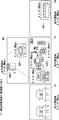
- FIG. 16 is a block diagram showing a configuration of a transmission system according to the fourth embodiment.
- FIG. 17 is a flowchart showing the operation of the transmission system according to the fourth embodiment.
- the transmission system 1 encodes an image taken by a plurality of cameras 10A to 10D mounted on the vehicle into a moving image and transmits the image.
- the transmission system 1 includes an information processing device 200 that analyzes an image taken by the in-vehicle camera 10, manages a communication band based on the analysis result, and transmits video data via the network 30.
- the video data is projected onto the projection system 40 in the remote monitoring center and presented to the remote driver.
- a physically single information processing device 200 is configured to collectively process a plurality of cameras. An example of the hardware configuration of the information processing device 200 is shown in FIG.
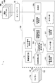
- the information processing apparatus 200 includes a band estimation unit 21, a camera band allocation unit 22, an object detection unit 201, an object state estimation unit 202, an object importance identification unit 208, and an object transmission band determination unit. It includes 211, a filter unit 203, a transmission area determination unit 204, an ROI (Region of Interest) area determination unit 207, an encoding unit 205, and a transmission unit 206.
- FIG. 17 shows a specific order of execution, but the order of execution may be different from the drawn form.
- the order of execution of two or more steps may be swapped with respect to the indicated order.
- the two or more steps shown in succession in FIG. 17 may be performed simultaneously or partially simultaneously. Further, in some embodiments, one or more steps shown in FIG. 17 may be skipped or omitted.
- the object detection unit 201 detects an object of interest from images taken by a plurality of cameras, and determines the type of the object, the position of the object in the image, and the size of the object in the image. Acquire (step S201).
- the object state estimation unit 202 estimates the distance from the vehicle to the object from the detected object type, the position of the object in the image, and the size of the object in the image (step). S202).
- the object importance specifying unit 208 specifies the importance of each camera based on the type of the object and the distance from the vehicle (step S203).
- the object importance specifying unit 208 refers to the distance threshold table (FIG. 10) described above, regards an object closer to the threshold as an important object, and describes the object importance table (FIG. 11) described above. Assign importance.
- the filter unit 203 filters out the objects that are not transmitted from the detected objects according to the distance of each object (step S204). By doing this, less important ones can be excluded. Further, as described above, an object capable of recognizing an object in a range that can be seen by a person with a visual acuity of 0.8 or more (for example, in the case of a road sign on a general road, the driver can recognize the sign at a distance of 10.66 m). Others can be excluded. As a result, the transmitted data can be reduced.
- the band estimation unit 21 estimates the usable band (step S205).
- the usable band constantly fluctuates, so the band estimation unit 21 estimates the usable band at a predetermined cycle (for example, every second).
- the object transmission band determination unit 211 determines the object transmission band according to the type of the object and the distance to the object (step S206).
- the object transmission band determination unit 211 obtains the bit rate conversion formula by referring to the bit rate conversion formula table shown in FIG. 19, substitutes the distance into the bit rate conversion formula, and determines the transmission bit rate of the object. In this way, the bit rate can be adjusted according to the difficulty of recognition depending on the distance and the object type.
- a and b of the bit rate conversion formula shown in FIG. 19 are arbitrary parameters, and x indicates the distance to the object.
- the ROI area determination unit 207 determines the ROI area for the object (step S207).
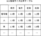
- FIG. 20 is a diagram illustrating an ROI area size determination process using an example of an image captured by each camera.
- Each ROI area size (FAF1', FAF2', FAF3', BAF1', RAF1' based on the ROI area size ratio table (FIG. 21) with respect to the size of the object considered to be important in the above-mentioned filter-out process. ) Is determined.
- the ROI area size of a moving body for example, a person or a car
- a fixed object for example, a traffic light
- the transmission area determination unit 204 determines the area and band of each layer according to the usable band, the transmission band of the target object, and the ROI area of the target object (step S208).
- the bit rate of the background area of each camera is set to the minimum bit rate of the background area, and the total bit rate of the background area is added to the band used.
- the objects having a short distance are added to the transmission object list, and the transmission bit rate of the object is added to the band used. This process is performed until there are no objects to be transmitted or the usable band falls below zero.
- the transmission band exceeds the limit usable band, the last added object (object o4) is deleted from the transmission object list.
- the remaining usable band is divided and assigned at the lowest bit rate ratio of the background area.
- the band of the background area can be increased, and the image of the background area of the highest quality possible can be transmitted to the remote driver while suppressing loss and delay.
- the coding unit 105 encodes the moving image according to the allocated band.
- the transmission unit 106 transmits the encoded moving image (step S208).
- the transmission system 1 can transmit high-quality video optimized for remote control while suppressing loss and delay. Further, according to the present embodiment, even if the object is a moving object, the ROI area can be expanded correspondingly, and even higher quality video can be transmitted. Further, in the present embodiment, by providing the object transmission band determination unit, the bit rate can be determined according to the difficulty of recognition depending on the distance and the object type.
- the system control device includes a band estimation unit that estimates the usable band, which is the band that can be used in the network, in order to transmit images taken by a plurality of cameras mounted on the vehicle, and the usable band and each camera. It is provided with a camera band allocation unit that allocates a band for each camera according to the importance of.
- Non-temporary computer-readable media include various types of tangible storage media.
- Examples of non-temporary computer-readable media include magnetic recording media, magneto-optical recording media (eg, magneto-optical disks), CD-ROMs (Read Only Memory), CD-Rs, CD-R / Ws, and semiconductor memories.
- the magnetic recording medium may be, for example, a flexible disk, a magnetic tape, or a hard disk drive.
- the semiconductor memory may be, for example, a mask ROM, a PROM (Programmable ROM), an EPROM (Erasable PROM), a flash ROM, or a RAM (Random Access Memory).
- the program may also be supplied to the computer by various types of temporary computer readable media.
- Examples of temporary computer-readable media include electrical, optical, and electromagnetic waves.
- the temporary computer-readable medium can supply the program to the computer via a wired communication path such as an electric wire and an optical fiber, or a wireless communication path.
- Appendix 1 It is a transmission method that transmits images taken by multiple cameras mounted on a vehicle via a network.
- a band estimation step for estimating the usable band which is the band that can be used in the network, and
- a camera band allocation step that allocates a band for each camera according to the available band and the importance of each camera, Sending method, including.
- (Appendix 2) It further includes the step of identifying the importance of each camera.
- An object state estimation step for estimating the distance from the vehicle to the object from the detected type of the object, the position of the object in the image, and the size of the object in the image.
- An object importance identification step for specifying the importance of an object based on the type of the object and the distance from the vehicle, and From the total value of the importance of the object detected for each camera, the camera importance specifying step for specifying the importance for each camera and the camera importance specifying step.
- the transmission method according to Appendix 1 which comprises. (Appendix 3) An area band allocation step for allocating a band for transmitting a moving image of a region in which the detected object is captured according to the band allocated for each camera and the importance of the object.
- the transmission method according to Appendix 2 further comprising.
- the object importance identification step is based on a distance threshold table showing the threshold value of the distance between the vehicle and each object and an object importance table showing the importance by associating the camera with each object.
- the transmission method described in Appendix 2 for specifying the importance. (Appendix 5) It further includes a vehicle condition detection step to detect the vehicle condition.
- the transmission method according to Appendix 4, wherein in the object importance specifying step, the distance threshold table and the object importance table are changed according to the vehicle state.
- the orientation of the object is estimated and the object is estimated.
- Appendix 10 The transmission method according to any one of Appendix 2 to 9, further comprising a filtering step of filtering out an object that is not transmitted from the detected moving image according to the distance to the object.
- Appendix 11 It is a transmission system that transmits images taken by multiple cameras mounted on a vehicle via a network.
- a band estimation unit that estimates the usable band, which is the band that can be used in the network, and
- a camera band allocation unit that allocates a band for each camera according to the available band and the importance of each camera, A transmission system.
- An object detection unit that detects an object of interest from images taken by the plurality of cameras and acquires the type of the object, the position of the object in the image, and the size of the object in the image.
- Object state estimation that estimates the distance from the vehicle to the object from the type of the detected object, the position of the object in the image, and the size of the object in the image.
- Department and An object importance specifying unit that specifies the importance of each camera based on the object type and the distance from the vehicle.
- the transmission system according to Appendix 12 further comprising an area band allocation unit that allocates a band for transmitting a moving image of the detected object area according to the importance of the camera band and the detection object.
- the object importance identification unit determines the importance based on the distance threshold table showing the threshold of the distance between the vehicle and each object and the object importance table showing the importance by associating the camera with each object.
- (Appendix 16) The object state estimation unit estimates the orientation of the object and The transmission system according to Appendix 14, wherein the object importance specifying unit changes the object importance table according to the orientation of the object.
- (Appendix 17) The transmission system according to Appendix 12, wherein the object state estimation unit estimates a distance by using a learning model different for each camera.
- (Appendix 18) The transmission system according to any one of Supplementary note 12 to 17, further comprising an ROI area determination unit that determines an ROI area of the object according to the type of the object and the size of the object.
- (Appendix 19) The transmission system according to Appendix 18, wherein the ROI region size when the detected object is a moving object is set to be larger than the ROI region size when the detected object is a fixed object.
- Appendix 20 The transmission system according to any one of Appendix 12 to 19, further comprising a filter unit that filters out an object that is not transmitted from the detected moving image according to the distance to the object.
- Appendix 21 A band estimation unit that estimates the usable band, which is the band that can be used in the network, to transmit images taken by multiple cameras mounted on the vehicle.
- a camera band allocation unit that allocates a band for each camera according to the available band and the importance of each camera, A system control unit.
- Appendix 22 To determine the importance of each camera An object detection unit that detects an object of interest from images taken by the plurality of cameras and acquires the type of the object, the position of the object in the image, and the size of the object in the image.
- Object state estimation unit that estimates the distance from the vehicle to the object from the type of the detected object, the position of the object in the image, and the size of the object in the image.
- An object importance specifying unit that specifies the importance of each camera based on the type of the object and the distance from the vehicle.
- the system control device according to Appendix 21, further comprising a camera importance specifying unit that specifies the importance of each camera from the total value of the importance of the object detected for each camera.
- a supplementary note further comprising an area band allocation unit that allocates a band for transmitting a moving image of a region in which the detected object is photographed according to the band allocated for each camera and the importance of the object. 22.
- the system control device is configured to estimate the distance from the vehicle to the object from the type of the detected object, the position of the object in the image, and the size of the object in the image.
- the object importance identification unit determines the importance based on the distance threshold table showing the threshold of the distance between the vehicle and each object and the object importance table showing the importance by associating the camera with each object.
- (Appendix 25) Further equipped with a vehicle condition detection unit that detects the vehicle condition, The system control device according to Appendix 24, wherein the object importance specifying unit changes the distance threshold table and the object importance table according to the vehicle state.
- Transmission system 3 Remote driver 5 Vehicle 10 In-vehicle camera 11 Band estimation unit 12 Camera band allocation unit 13 Vehicle condition detection unit 21 Band estimation unit 22 Camera band allocation unit 30 Network 40 Projection system 100 Information processing device 101 Object detection unit 102 Object state estimation unit 103 Camera importance identification unit 104 Area band allocation unit 105 Coding unit 106 Transmission unit 108 Object importance identification unit 201 Object detection unit 202 Object state estimation unit 203 Filter unit 204 Transmission area determination unit 205 Encoding unit 206 Transmission unit 207 ROI area determination unit 208 Object importance identification unit 211 Object transmission band determination unit 400 Ground monitoring remote control device FA Front area BA Rear area RA Right area LA Left area
Landscapes
- Engineering & Computer Science (AREA)
- Multimedia (AREA)
- Signal Processing (AREA)
- Physics & Mathematics (AREA)
- General Physics & Mathematics (AREA)
- Theoretical Computer Science (AREA)
- Computer Vision & Pattern Recognition (AREA)
- Traffic Control Systems (AREA)
- Closed-Circuit Television Systems (AREA)
Abstract
ロスや遅延を抑制しつつ、遠隔運転に適した高品質な映像を送信可能な送信方法、送信システム及びシステム制御装置を提供する。送信方法は、車両(5)に搭載された複数台のカメラ(10)が撮影した画像を、ネットワーク(30)を介して送信する送信方法であって、ネットワークの使用可能帯域を推定する帯域推定ステップ(S11)と、使用可能帯域とカメラ毎の重要度に応じて、カメラ毎に帯域を割り当てるカメラ帯域割当ステップ(S12)と、を含む。
Description
本開示は、送信方法、送信システム及びシステム制御装置に関する。
携帯電話網経由での車両遠隔監視・制御では可用帯域が変動することから帯域不足による映像品質悪化が懸念される。これまでに、予測した通信スループットにあわせて送信する動画像のビットレートを動的に調整する手法が提案されている。しかし、一律に動画像の画質を調整するため、やはり帯域低下時に遠隔監視・制御に必要な情報を提供できない恐れがある。そこで、運転上重要なカメラ映像・領域のみを高画質化して送信することにより必要な情報を提供する方法が期待される。
非特許文献1には、視聴者が見ていない領域を低画質化し、人間が自然に注視する視覚的に顕著な領域を重要領域として高画質化する技術が開示されている。重要領域の選択方法としては、輝度、色相成分、エッジの向きから算出する顕著性マップ算出アルゴリズムがある。これにより限られた帯域でも高QoEな映像の配信が可能である。
こうした技術を遠隔運転に適用することで、人間が注視しやすい重要領域を高画質で送信することで、高QoE(quality of experience)な映像を配信することができる。しかしながら、この技術は、遠隔運転に適したものではない。すなわち、顕著性が低くても、遠隔運転者にとって重要であるものがあるし、顕著性が高くても、遠隔運転者にとって重要でないものもある。そのため、依然として、不必要なロスや遅延が発生する場合がある。
本発明は、このような問題点を解決するためになされたものであり、ロスや遅延を抑制しつつ、遠隔運転に適した高品質な映像を送信可能な送信方法、送信システム及びシステム制御装置を提供することを目的とする。
本開示の第1の態様にかかる送信方法は、車両に搭載された複数台のカメラが撮影した画像を、ネットワークを介して送信する送信方法であって、
前記ネットワークで使用可能な帯域である使用可能帯域を推定する帯域推定ステップと、
前記使用可能帯域とカメラ毎の重要度に応じて、カメラ毎に帯域を割り当てるカメラ帯域割当ステップと、
を含む。
前記ネットワークで使用可能な帯域である使用可能帯域を推定する帯域推定ステップと、
前記使用可能帯域とカメラ毎の重要度に応じて、カメラ毎に帯域を割り当てるカメラ帯域割当ステップと、
を含む。
本開示の第2の態様にかかる送信システムは、
車両に搭載された複数台のカメラが撮影した画像を、ネットワークを介して送信する送信システムであって、
前記ネットワークで使用可能帯域を推定する帯域推定部と、
前記使用可能帯域とカメラ毎の重要度に応じて、カメラ毎に帯域を割り当てるカメラ帯域割当部と、
を備える。
車両に搭載された複数台のカメラが撮影した画像を、ネットワークを介して送信する送信システムであって、
前記ネットワークで使用可能帯域を推定する帯域推定部と、
前記使用可能帯域とカメラ毎の重要度に応じて、カメラ毎に帯域を割り当てるカメラ帯域割当部と、
を備える。
本開示の第3の態様にかかるシステム制御装置は、
車両に搭載された複数台のカメラが撮影した画像を送信するために、ネットワークで使用可能な帯域である使用可能帯域を推定する帯域推定部と、
前記使用可能帯域とカメラ毎の重要度に応じて、カメラ毎に帯域を割り当てるカメラ帯域割当部と、
を備える。
車両に搭載された複数台のカメラが撮影した画像を送信するために、ネットワークで使用可能な帯域である使用可能帯域を推定する帯域推定部と、
前記使用可能帯域とカメラ毎の重要度に応じて、カメラ毎に帯域を割り当てるカメラ帯域割当部と、
を備える。
本開示により、ロスや遅延を抑制しつつ、遠隔運転に適した高品質な映像を送信可能な送信方法、送信システム及びシステム制御装置を提供することができる。
図1を参照して遠隔監視運転システムの概要を説明する。
遠隔監視運転システムは、遠隔監視センタから、運転手を必要としない車両5を遠隔操作する。無人運転車両5を遠隔操作する方式としては、車両5に搭載された複数台の車載カメラ10A~10Dで撮影された映像を、無線通信ネットワークおよびインターネットを介して地上監視制御装置400に送信する。遠隔運転者3が、受信した映像をモニター上で見ながら遠隔操作する。車両5に搭載された遠隔運転制御装置は、携帯電話網を使用した通信方式(例えば、LTE、5G)を利用して地上監視遠隔制御装置400と双方向通信を行う。なお、遠隔監視運転システムは、遠隔監視下にある車両が走行中に、車両の危険を察知した際に、遠隔制御や自動制御に切り替えるものであってもよい。すなわち、人が運転している車両を一次的にこうした制御に切り替えるものであってもよく、車両に運転手がいてもよい。
車載カメラ10Aは車両の前方を撮影し、車載カメラ10Bは車両の後方を撮影し、車載カメラ10Cは車両の右方を撮影し、車載カメラ10Dは車両の左方を撮影する。なお車載カメラの数は、これに限定されず、5個以上であってもよい。また、各カメラの性能は、基本的には同一であるが、若干異なっていてもよい。なお、タクシーなどの通常の運転手は、第二種免許が要求され、それには、視力0.8以上の人が見える範囲の対象物(物体とも呼ばれる)を認識できることが要求されている。そのため、遠隔運転者に提供される映像も、視力0.8以上の人が見える範囲の対象物を認識できる(例えば一般道の道路標識の場合は、運転手が10.66mの距離離れて標識を認識できる)ものであることが望ましい。遠隔運転者は、対象物だけでなく、対象物の周辺情報も視認する必要があり、こうした周辺情報も比較的高品質な映像として、遠隔運転者に送信することが望ましい。
図2は、モバイル網経由での遠隔監視システムにおける帯域不足を説明する図である。
図2に示すように、各カメラ10A~10Dで撮影された各映像は、携帯電話網を介して一律に送信される。しかし、携帯電話網では、使用可能な帯域(以降、使用可能帯域と記載することもある)が変動し得るため、帯域不足により映像品質が悪化する場合がある。映像が通信帯域以上のビットレートで送信された場合には、通信ネットワークにおいて、ロスや遅延が発生し得る。本発明はこのような問題を解決するものである。すなわち、本発明は、車載カメラが撮影した画像から、遠隔運転者が注視すべき画像領域を決定する機能と、複数台のカメラのうち、重要なカメラを決定するとともに、カメラ画像の中から、遠隔運転に重要な領域を自動的に抽出する機能を有する。また、本システムでは、車載計算機資源には制限があるため、計算機資源が潤沢な遠隔運転者側の計算機との連携が必要となり得る。
図2に示すように、各カメラ10A~10Dで撮影された各映像は、携帯電話網を介して一律に送信される。しかし、携帯電話網では、使用可能な帯域(以降、使用可能帯域と記載することもある)が変動し得るため、帯域不足により映像品質が悪化する場合がある。映像が通信帯域以上のビットレートで送信された場合には、通信ネットワークにおいて、ロスや遅延が発生し得る。本発明はこのような問題を解決するものである。すなわち、本発明は、車載カメラが撮影した画像から、遠隔運転者が注視すべき画像領域を決定する機能と、複数台のカメラのうち、重要なカメラを決定するとともに、カメラ画像の中から、遠隔運転に重要な領域を自動的に抽出する機能を有する。また、本システムでは、車載計算機資源には制限があるため、計算機資源が潤沢な遠隔運転者側の計算機との連携が必要となり得る。
そこで、本発明では、検出対象物と車との距離を推定し、対象物毎の重要度を決定し、重要度の高い対象物のある領域を優先的に高精細化して、遠隔運転者側の遠隔制御装置に送信する。重要度は対象物(物体)の種別や車両から対象物までの距離から算出する。物体種別毎に画像内での位置・サイズに対する実際の距離および向きを事前に学習しておき、システム実施時に、画像から、対象物までの距離および対象物の向きを推定する。各カメラが撮影した画像内の対象物全ての重要度合計値が高いカメラに対して使用可能帯域を多く配分する。カメラ毎に注視する必要のある対象物は異なり、カメラの優先度も異なるためカメラ毎に物体種別毎に距離および向きに対する重要度を設定しておく。
具体的には、本システムにより実施される方法は、事前作業(学習)と、システム実施時の工程を含む。事前作業としては、各カメラが撮影した画像内位置・サイズに対する車からの距離を計測し学習し、カメラおよび物体の種別毎に車からの距離に対する重要度を設定しておく。また、システム実施時は、各カメラで撮影した画像中の物体を認識し、物体の画像内位置、サイズ、物体の種別を取得する。また、事前に設定したカメラおよび物体種別毎に車からの距離、向きに対する重要度と、認識物体の位置、サイズ、種別から重要度を特定する。さらに、カメラ毎に撮影された物体の重要度合計値を算出し使用可能帯域から各カメラに対して重要度に応じて帯域を配分する。各カメラ内で物体が存在する領域に対して配分された帯域と物体の重要度から領域に帯域を配分する。こうすることで、限られた帯域でも遠隔運転者が運転に影響を与える物体を認識できる確率を高めることができる。以下、図面を参照して本発明の実施の形態について説明する。
(実施の形態1)
図3は、実施の形態1にかかる送信システムでの構成を示すブロック図である。実施の形態1にかかる送信システムは、図3に示すように、帯域推定部11と、カメラ帯域割当部12と、を備える情報処理装置100(ハードウェア構成については、図26を用いて後述)を含む。送信システムは、車両に搭載された複数台のカメラが撮影した画像を、ネットワークを介して送信する送信システムであって、ネットワークの使用可能帯域を推定する帯域推定部11と、使用可能帯域とカメラ毎の重要度に応じて、カメラ毎に帯域を割り当てるカメラ帯域割当部12と、を備える。なお、情報処理装置100は、システム制御装置と呼ばれ得る。
図3は、実施の形態1にかかる送信システムでの構成を示すブロック図である。実施の形態1にかかる送信システムは、図3に示すように、帯域推定部11と、カメラ帯域割当部12と、を備える情報処理装置100(ハードウェア構成については、図26を用いて後述)を含む。送信システムは、車両に搭載された複数台のカメラが撮影した画像を、ネットワークを介して送信する送信システムであって、ネットワークの使用可能帯域を推定する帯域推定部11と、使用可能帯域とカメラ毎の重要度に応じて、カメラ毎に帯域を割り当てるカメラ帯域割当部12と、を備える。なお、情報処理装置100は、システム制御装置と呼ばれ得る。
図4は、実施の形態1にかかる送信システムの動作を示すフローチャートである。本実施の形態にかかる送信方法は、図4に示すように、車両に搭載された複数台のカメラが撮影した画像を、ネットワークを介して送信する送信方法であって、ネットワークの使用可能帯域を推定する帯域推定ステップ(ステップS11)と、使用可能帯域とカメラ毎の重要度に応じて、カメラ毎に帯域を割り当てるカメラ帯域割当ステップ(ステップS12)と、を含む。
以上説明した実施の形態1によれば、カメラ毎の重要度に応じて、帯域を割り当てることで、ロスや遅延を抑制しつつ、遠隔運転に適した高品質な映像を送信可能な送信方法、送信システムを提供することができる。
(実施の形態2)
図5は、実施の形態2にかかる送信システム1の構成を示すブロック図である。図6は、実施の形態2にかかる送信システムの動作を示すフローチャートである。
送信システム1は、車両に搭載された複数台のカメラ10A~10Dが撮影した画像を動画像に符号化し送信するものである。送信システム1は、車載カメラ10が撮影した画像を解析し、解析結果に基づき通信帯域を管理し、ネットワーク30を介して映像データを送信する情報処理装置100を備える。映像データは、遠隔監視センタにある、投影システム40に投影されて、遠隔運転者に提示される。なお、本実施の形態では、物理的に単一の情報処理装置100が、複数台のカメラに対して統括的に処理するように構成する。図26は、情報処理装置100(又は10、200)のハードウェア構成例を示すブロック図である。図26に示すように、本実施形態の情報処理装置100(又は10、200)は、CPU(Central Processing Unit)401、RAM(Random access memory)402、ROM(Read Only Memory)403などを有するコンピュータである。CPU401は、RAM402、ROM403、または、ハードディスク404に格納されたソフトウェアに従い演算および制御を行う。RAM402は、CPU401が各種処理を実行する際の一時記憶領域として使用される。ハードディスク404には、オペレーティングシステム(OS)や、後述の登録プログラムなどが記憶される。ディスプレイ405は、液晶ディスプレイとグラフィックコントローラとから構成され、ディスプレイ405には、画像やアイコンなどのオブジェクト、および、GUIなどが表示される。入力部406は、ユーザが端末装置に各種指示を与えるための装置であり、例えばマウスやキーボードによって構成される。I/F(インターフェース)部407は、IEEE 802.11aなどの規格に対応した無線LAN通信や有線LAN通信を制御することができ、TCP/IPなどのプロトコルに基づき同一通信ネットワークおよびインターネットを介して外部機器と通信する。システムバス408は、CPU401、RAM402、ROM403、および、ハードディスク404などとのデータのやり取りを制御する。制御部は、細分化された処理のそれぞれを実行する機能演算部としての機能も担う。
図5に示すように、情報処理装置100は、帯域推定部11、カメラ帯域割当部12、対象物検出部101、対象物状態推定部102、対象物重要度特定部108、カメラ重要度特定部103、領域帯域割当部104、符号化部105、及び送信部106を備える。
図6を参照して、本実施の形態にかかる送信方法を説明する。図6のフローチャートは、実行の具体的な順番を示しているが、実行の順番は描かれている形態と異なっていてもよい。例えば、2つ以上のステップの実行の順番は、示された順番に対して入れ替えられてもよい。また、図6の中で連続して示された2つ以上のステップは、同時に、または部分的に同時に実行されてもよい。さらに、いくつかの実施形態では、図6に示された1つまたは複数のステップがスキップまたは省略されてもよい。
対象物検出部101は、複数台のカメラで撮影した画像から目的の対象物を検出して、対象物の種別、画像内での対象物の位置、及び画像内での対象物の大きさを取得する(ステップS1)。対象物状態推定部102は、検出された対象物の種別、画像内での対象物の位置、及び画像内での対象物の大きさから、車両から対象物までの距離を推定する(ステップS2)。対象物重要度特定部108は、対象物種別及び車両(車載カメラ)からの距離に対する重要度を、カメラ毎に関連付けて管理し、それに基づいて検出対象物の重要度を特定する(ステップS3)。カメラ重要度特定部103は、カメラ毎に検出された検出対象物の重要度の合計値から、カメラ毎の重要度を特定する(ステップS4)。
帯域推定部11は使用可能帯域を推定する(ステップS5)。携帯電話網では、使用可能帯域が常時変動するため、帯域推定部11は、所定周期(例えば、1秒毎)で使用可能帯域を推定する。カメラ帯域割当部12は、推定された使用可能帯域とカメラ毎の重要度に応じて、カメラ毎に帯域を割り当てる(ステップS6)。領域帯域割当部104は、カメラ毎に割り当てられた帯域(カメラ帯域とも呼ばれる場合がある)と対象物の重要度に応じて検出された対象物を撮影した領域の動画像の送信にかかる帯域を割り当てる(ステップS7)。符号化部105は、割当帯域にしたがって動画像に符号化する。送信部106を符号化された動画像を送信する(ステップS8)。
以上説明した本実施の形態にかかる送信方法および送信システム1は、ロスや遅延を抑制しつつ、遠隔運転に適した高品質な映像を送信することができる。
(実施の形態3)
図7は、実施の形態3にかかる送信システム1の構成を示すブロック図である。図7では、実施の形態2と同一の構成要素は、図5と同一の符号を付し、適宜説明を省略する。本実施の形態は、実施の形態2の動作をより詳細に規定するものであるが、実施の形態2のフローチャートである図6を参照して、以下に説明する。
図7は、実施の形態3にかかる送信システム1の構成を示すブロック図である。図7では、実施の形態2と同一の構成要素は、図5と同一の符号を付し、適宜説明を省略する。本実施の形態は、実施の形態2の動作をより詳細に規定するものであるが、実施の形態2のフローチャートである図6を参照して、以下に説明する。
本システムでは、図7に示すように、複数の情報処理装置100A~100Dが、各車載カメラ10A~10Dに対応して設けられている。このように、本システムは、複数の情報処理装置100A~100Dを有し、複数台のカメラからの映像を分散的に処理するように構成される。さらに、本システムは、使用可能な帯域を推定する帯域推定部11と、推定された使用可能帯域およびカメラ毎のカメラの重要度に基づいて各カメラに帯域を割り当てるカメラ帯域割当部12とを含む情報処理装置10を統括的に備える。更に、本実施の形態では、車両が前進中か、後進中か、左折中か、それとも右折中か等の車両状態を検出する車両状態検出部23が統括的に情報処理装置10に追加されている。車両状態検出部23は、例えば、各カメラが撮影した映像に基づき、車両状態を推定してもよいし、車載ネットワークCAN(Controller Area Network)を通じて、車両状態を検出してもよい。あるいは、車両状態検出部13は、車両のギアがどこに入っているか(ドライブ又はリバース等)やセンサで判定することもできる。
なお、本システムは、情報処理装置10を統括的に備える構成としたが、これに限定されず、帯域推定部11、カメラ帯域割当部12、車両状態検出部13も、各情報処理装置100A~100Dに分散して構成してもよい。
図8を参照して、本実施の形態にかかる対象物検出部101および対象物状態推定部102の動作を詳細に説明する。
図8は、各カメラが撮影した映像の一例を用いて、対象物検出処理(ステップS1)および対象物状態推定処理(ステップS2)を説明する図である。なお、こうした映像は、図1で示した地上監視遠隔制御装置400において、遠隔運転者3が閲覧するモニターに表示されてもよいし、車両5に搭載したモニターに表示してもよい。
図8は、各カメラが撮影した映像の一例を用いて、対象物検出処理(ステップS1)および対象物状態推定処理(ステップS2)を説明する図である。なお、こうした映像は、図1で示した地上監視遠隔制御装置400において、遠隔運転者3が閲覧するモニターに表示されてもよいし、車両5に搭載したモニターに表示してもよい。
前方車載カメラ10Aが撮影した映像は、前方領域映像FAとして示されている。後方車載カメラ10Bが撮影した映像は、後方領域映像BAとして示されている。右方車載カメラ10Cが撮影した映像は、右方領域映像RAとして示されている。左方車載カメラ10Dが撮影した映像は、左方領域映像LAとして示されている。
まず、対象物検出部101は、各カメラが撮影した画像データに対して、信号機、道路標識、人、車、バス、トラック、バイク、及び自転車などの対象物を検出する(ステップS1)。対象物検出部101は、深層学習による対象物の検出を行うことができ、事前にこれらの画像を学習したモデルを活用することができる。
図8に示すように、前方領域映像FAには、対象物を囲う3つの注視領域が検出される。すなわち、前方領域注視領域FAF1には、対向車が検出され、前方領域注視領域FAF2には、人が検出され、前方領域注視領域FAF3には、信号機が検出されている。
また、後方領域映像BAには、2つの注視領域が検出される。すなわち、後方領域注視領域BAF1には、後続車が検出され、後方領域注視領域BAF2には、信号機が検出されている。さらに、右方領域映像RAには、1つの注視領域が検出される。すなわち、右方領域注視領域BAF1には、バスが検出されている。一方、左方領域映像LAには、注視領域として検出されるものはない。これら注視領域として検出される対象物は、遠隔運転者にとって注視すべきものである。これら注視領域以外の領域は、非注視領域と呼ばれ、遠隔運転者にとって重要でないもの(例えば、空中を飛んでいるヘリコプター、道路脇に並ぶ店舗や家、ビル、塔など)を含む領域である。
次に、対象物状態推定部102は、対象物検出部101による検出結果を用い、自車両(車載カメラ)からの検出対象物までの距離を推定する(ステップS2)。車載カメラは、車両に固定されており、映像に映る範囲(画角)も固定されているので、対象物状態推定部102は、画像内での位置および大きさ(形状)に基づいて、対象物までの距離を推定することができる。また、対象物状態推定部102は、深層学習による距離および向きを推定してもよい。すなわち、事前にこれらの対象物の画像を検出した結果とそれに対する車の距離や、車に対する向きを学習しておいてもよい。さらに、カメラ毎に対象物の見え方(画角)が異なることから、精度向上のためカメラ毎に学習モデルを構築することが望ましい。すなわち、対象物状態推定部102A~102Dはそれぞれ、異なる学習モデルを用いる。こうした学習モデルは、対象物状態推定部102A~102D内部の記憶部に記憶されていても良いし、あるいは、対象物状態推定部102A~102Dとネットワークを介して接続された外部記憶部に記憶されていても良い。あるいは、カメラ毎に構築された学習モデルは、本システムを統括的に管理する情報処理装置の記憶部に格納されてもよい。
こうして、対象物状態推定部102A~102Dは、車載カメラ10A~10Dから対象物までの距離を推定する。例えば、図8に示すように、前方領域注視領域FAF1の対向車は車載カメラ10Aから8mにあり、前方領域注視領域FAF2の人は車載カメラ10Aから10mにあり、前方領域注視領域FAF3の信号機は車載カメラ10Aから14mにある。後方領域注視領域BAF1の後続車は車載カメラ10Dから5mにあり、後方領域注視領域BAF2の信号機は車載カメラ10Dから15mにある。さらに、右方領域注視領域BAF1のバスは車載カメラ10Cから4mにある。なお、本図の中に記載している対象物名(BAF1等)や、距離(4m)、割り当て帯域(0.4Mbps)等は、モニター等に表示される映像上に表示しても良いし、表示しなくても良い。
次に、図9~図11を参照して対象物重要度特定処理(ステップS3)を説明する。
図9は、各カメラが撮影した映像の一例を用いて、対象物重要度特定処理を説明する図である。なお、図9の映像は、図8の映像と同一である。
図9は、各カメラが撮影した映像の一例を用いて、対象物重要度特定処理を説明する図である。なお、図9の映像は、図8の映像と同一である。
カメラ毎に検出された対象物の重要度が異なる(例えば、車両の前方の信号機は重要であるが、車両の後方の信号機は重要性が低い)ので、対象物重要度特定部108A~108Dは、それぞれ異なる距離閾値テーブルおよび対象物重要度テーブルを管理する。図10は、対象物重要度特定部108Aが管理する距離閾値テーブルの一例を示す。図11は、対象物重要度特定部108Aが管理する対象物重要度テーブルの一例を示す。なお、上記した距離閾値テーブルおよび対象物重要度テーブルは、車両が前進している場合のものであり、車両が後進中、左折中、右折中など、車両の状態に応じて、これらのテーブルは異なってもよい。すなわち、対象物重要度特定部108は、車両状態検出部23により検出された車両状態に応じて、距離閾値テーブルおよび対象物重要度テーブルを変更してもよい。
対象物重要度特定部108は、対象物状態推定部102により推定された、車両と対象物までの距離だけでなく、対象物の向き(すなわち、対象物が車の場合、対向車、先行車、右側又は左側からの侵入車)に応じて、距離閾値テーブルおよび対象物重要度テーブルを変更してもよい。
また、検出すべき対象物は、固定物(例えば、信号機)と移動体(例えば、車、人)を含む。対象物が移動体の場合は、対象物の時系列での予測位置(=動き)を保持し、移動速度に応じて領域サイズを拡大縮小し、高確率に対象物がある領域を取得してもよい。すなわち、移動速度が増大するにつれて対象物を囲う領域サイズを拡大してもよい。さらに、対象物位置予測部より対象物予測位置に加え予測誤差または確信度(confidence)または確率分布を出力し領域サイズを拡大縮小し高確率に対象物がある領域を取得してもよい。
図10および図11に示すように、対象物の種別毎に決められた距離以内の対象物に対して、固定的に重要度が決められている。例えば、車両の前方15m以内の信号機は、10m以内の人、10m以内の車は重要と設定されている。また、車両の後方5m以内の車は、重要であると設定されている。また、車両の左側および右側10m以内の信号機、5m以内の人、3m以内の車は、重要であると設定されている。
重要度特定処理は、距離閾値テーブル(図10)を参照し閾値より近い対象物を重要対象物とみなし、その重要対象物に対し、対象物重要度テーブル(図11)に記載の重要度を割り当てることによって行われる。図9に示すように、前方領域注視領域FAF1の対向車は8mであるので、0.4が、前方領域注視領域FAF2の人は10mであるので、0.3が、前方領域注視領域FAF3の信号機は14mであるので、0.5が割り当てられる。後方領域注視領域BAF1の後続車は5mであるので、0.3が、後方領域注視領域BAF2の信号機は15mであるので、0が割り当てられる。さらに、右方領域注視領域BAF1のバスは4mであるので、0.2が割り当てられる。
次に、図12及び図13を参照してカメラ重要度特定処理(ステップS4)を説明する。図11は、各カメラが撮影した映像の一例を用いて、カメラ重要度特定処理を説明する図である。図13は、非注視領域重要度テーブルの一例である。
カメラ重要度特定部103Aは、カメラが撮影した全検出対象物の重要度および非注視領域重要度の合計値からカメラ重要度を特定する(ステップS4)。非注視領域とは、各カメラが撮影した画面全体のうち、検出対象物を囲う注視領域以外の領域をいう。図13の非注視領域重要度テーブルに示すように、非注視領域の重要度は、各カメラ(前方、後方、左側、右側)に応じて異なっている。
例えば、前方領域映像FAのカメラ重要度は、各検出対象物(対向車、人及び信号機)の重要度の合計(すなわち、0.4+0.3+0.5)に前方の非注視領域の重要度(すなわち、0.5)を加えることで、1.7と算出される。
同様に、後方領域映像BAのカメラ重要度は、各検出対象物(後続車、及び信号機)の重要度の合計(すなわち、0.3+0)に後方の非注視領域の重要度(すなわち、0.2)を加えることで、0.5と算出される。右方領域映像RAの重要度は、検出対象物(バス)の重要度の合計(0.2)に右方の非注視領域の重要度(0.3)を加えることで、0.5と算出される。左方領域映像LAの重要度は、検出対象物はないので、左方の非注視領域の重要度から0.3と算出される。
次に、図14を参照して使用可能帯域推定処理(ステップS5)及びカメラ帯域割当処理(ステップS6)を説明する。
帯域推定部11は使用可能帯域を推定する(ステップS5)。携帯電話網では、使用可能帯域が常時変動するため、帯域推定部11は、所定周期(例えば、1秒毎)で使用可能帯域を推定する。図14では、上り使用可能帯域が6Mbpsと推定される。
帯域推定部11は使用可能帯域を推定する(ステップS5)。携帯電話網では、使用可能帯域が常時変動するため、帯域推定部11は、所定周期(例えば、1秒毎)で使用可能帯域を推定する。図14では、上り使用可能帯域が6Mbpsと推定される。
次に、カメラ帯域割当部12は使用可能帯域(6Mbps)および、上記したカメラ毎のカメラ重要度に応じて、カメラ毎に帯域を割り当てる(ステップS6)。前述したように、前方カメラの重要度は1.7、後方カメラの重要度は0.5、左側カメラの重要度は0.3、右側カメラの重要度は、0.5である。前方カメラの割当帯域は、推定された上り使用可能帯域(6Mbps)に1.7/3.0を乗算することで、3.4Mbpsと算出される。同様に、後方カメラの割当帯域は、1.0Mbps、左側カメラの割当帯域は、0.6Mbps、右側カメラの割当帯域は、1.0Mbpsと算出される。
最後に、図15を参照して検出対象物帯域割当処理(ステップS7)を説明する。
領域帯域割当部104Aはカメラ帯域から検出対象物の重要度に応じて検出対象物の送信にかかる帯域を割り当てる(ステップS7)。各検出対象物の領域割当帯域は、検出対象物の重要度に応じて比例配分で割り当てられる。例えば、前方領域FAでは、前方領域注視領域FAF1の対向車に対する領域割当帯域は、3.4Mbpsに0.4/1.7を乗算することで、0.8Mbpsと算出される。前方領域注視領域FAF2の人に対する領域割当帯域は、3.4Mbpsに0.3/1.7を乗算することで、0.6Mbpsと算出される。前方領域注視領域FAF3の信号機に対する領域割当帯域は、3.4Mbpsに0.5/1.7を乗算することで、1.0Mbpsと算出される。更に、前方領域のうち非注視領域に対する領域割当帯域は、3.4Mbpsに0.5/1.7を乗算することで、1.0Mbpsと算出される。
領域帯域割当部104Aはカメラ帯域から検出対象物の重要度に応じて検出対象物の送信にかかる帯域を割り当てる(ステップS7)。各検出対象物の領域割当帯域は、検出対象物の重要度に応じて比例配分で割り当てられる。例えば、前方領域FAでは、前方領域注視領域FAF1の対向車に対する領域割当帯域は、3.4Mbpsに0.4/1.7を乗算することで、0.8Mbpsと算出される。前方領域注視領域FAF2の人に対する領域割当帯域は、3.4Mbpsに0.3/1.7を乗算することで、0.6Mbpsと算出される。前方領域注視領域FAF3の信号機に対する領域割当帯域は、3.4Mbpsに0.5/1.7を乗算することで、1.0Mbpsと算出される。更に、前方領域のうち非注視領域に対する領域割当帯域は、3.4Mbpsに0.5/1.7を乗算することで、1.0Mbpsと算出される。
同様に、後方領域BAでは、後方領域注視領域BAF1の後続車に対する領域割当帯域は、1.0Mbpsに0.3/0.5を乗算することで、0.6Mbpsと算出される。後方領域のうち非注視領域に対する領域割当帯域は、1.0Mbpsに0.2/0.5を乗算することで、0.4Mbpsと算出される。
左方領域LAでは、検出対象物はない。非注視領域に対する領域割当帯域は、0.6Mbpsに0.3/0.3を乗算することで、0.6Mbpsと算出される。
右方領域RAでは、右方領域注視領域BAF1のバスに対する領域割当帯域は、1.0Mbpsに0.2/0.5を乗算することで、0.4Mbpsと算出される。右方領域の非注視領域に対する領域割当帯域は、1.0Mbpsに0.3/0.5を乗算することで、0.6Mbpsと算出される。以上のように、領域帯域割当部104は、検出された対象物全てに対する領域帯域を割り当てる。送信部106は、割当帯域にしたがって動画像に符号化して動画像を送信する(ステップS8)。
以上説明した本実施の形態にかかる送信システムは、ロスや遅延の発生を抑制しつつ、遠隔運転に適した高品質な映像を送信することができる。また、カメラ毎に遠隔運転者にとって重要となり得る対象物を選択的に検出し、こうした対象物を比較的高品質な映像で送信することができる。換言すれば、遠隔運転者にとって重要となり得ない対象物には、割当帯域を低減することで、モバイル通信網におけるロスや遅延の発生を抑制することができる。
(実施の形態4)
図16及び図17を参照して、実施の形態4にかかる送信システムを説明する。
図16は、実施の形態4にかかる送信システムの構成を示すブロック図である。図17は、実施の形態4にかかる送信システムの動作を示すフローチャートである。
図16及び図17を参照して、実施の形態4にかかる送信システムを説明する。
図16は、実施の形態4にかかる送信システムの構成を示すブロック図である。図17は、実施の形態4にかかる送信システムの動作を示すフローチャートである。
送信システム1は、車両に搭載された複数台のカメラ10A~10Dが撮影した画像を動画像に符号化し送信するものである。送信システム1は、車載カメラ10が撮影した画像を解析し、解析結果に基づき通信帯域を管理し、ネットワーク30を介して映像データを送信する情報処理装置200を備える。映像データは、遠隔監視センタにある、投影システム40に投影されて、遠隔運転者に提示される。なお、本実施の形態では、物理的に単一の情報処理装置200が、複数台のカメラに対して統括的に処理するように構成する。情報処理装置200のハードウェアの構成例は、図26に示す。
図16に示すように情報処理装置200は、帯域推定部21、カメラ帯域割当部22、対象物検出部201、対象物状態推定部202、対象物重要度特定部208、対象物送信帯域決定部211、フィルタ部203、送信領域決定部204、ROI(Region of Interest)領域決定部207、符号化部205、及び送信部206を備える。
図17を参照して、本実施の形態にかかる送信システムの動作を説明する。図17のフローチャートは、実行の具体的な順番を示しているが、実行の順番は描かれている形態と異なっていてもよい。例えば、2つ以上のステップの実行の順番は、示された順番に対して入れ替えられてもよい。また、図17の中で連続して示された2つ以上のステップは、同時に、または部分的に同時に実行されてもよい。さらに、いくつかの実施形態では、図17に示された1つまたは複数のステップがスキップまたは省略されてもよい。
対象物検出部201は、複数台のカメラで撮影した画像から目的の対象物を検出して、対象物の種別、画像内での対象物の位置、及び画像内での対象物の大きさを取得する(ステップS201)。対象物状態推定部202は、検出された対象物の種別、画像内での対象物の位置、及び画像内での対象物の大きさから、車両から前記対象物までの距離を推定する(ステップS202)。これらの対象物検出処理及び距離推定処理は、前述した実施の形態2のステップS1及びステップS2と同様であり、詳しい説明は省略する。
対象物重要度特定部208は、対象物の種別及び車両からの距離に基づいて、カメラ毎の重要度を特定する(ステップS203)。対象物重要度特定部208は、前述した距離閾値テーブル(図10)を参照して、閾値より近くにある対象物を重要物体とみなし、前述の対象物重要度テーブル(図11)に記載の重要度を割り当てる。
図18に示すように、フィルタ部203は、対象物毎の距離に応じて、検出した対象物から送信しない対象物をフィルタアウトする(ステップS204)。こうすることで、重要度の低いものを除外することができる。さらに、前述したように、視力0.8以上の人が見える範囲の対象物を認識できる(例えば一般道の道路標識の場合は、運転手が10.66mの距離離れて標識を認識できる)もの以外を、除外することもできる。結果的に、送信データを削減することができる。
帯域推定部21は使用可能帯域を推定する(ステップS205)。携帯電話網では、使用可能帯域が常時変動するため、帯域推定部21は、所定周期(例えば、1秒毎)で使用可能帯域を推定する。
対象物送信帯域決定部211は、対象物の種別及び対象物までの距離に応じて、対象物の送信帯域を決定する(ステップS206)。対象物送信帯域決定部211は、図19に示すビットレート変換式テーブルを参照してビットレート変換式を取得し、ビットレート変換式に距離を代入して、オブジェクトの送信ビットレートを決定する。このように、距離と物体種別に依存する認識の難しさに応じて、ビットレートを調整することができる。図19に示す、ビットレート変換式のa、bは任意のパラメータであり、xは、対象物までの距離を示す。
ROI領域決定部207は、対象物に対するROI領域を決定する(ステップS207)。図20は、各カメラが撮影した映像の一例を用いて、ROI領域サイズ決定処理を説明する図である。前述したフィルタアウト処理で重要とみなされた対象物のサイズに対して、ROI領域サイズ比率テーブル(図21)に基づき、各ROI領域サイズ(FAF1’、FAF2’、FAF3’、BAF1’、RAF1’)が決定される。図21に示すように、移動体(例えば、人や車)のROI領域サイズは、固定物(例えば、信号機)のROI領域サイズより大きくなるように設定されている。これにより、動く対象物は、位置予測精度が低く、対象物に対するROI領域を大きく設定することができ、注視領域に物体が収まる確率を高まることができる。
送信領域決定部204は、使用可能帯域、対象物の送信帯域、対象物のROI領域に応じて、各レイヤの領域及び帯域を決定する(ステップS208)。ここで、図22~図25を参照して、送信領域決定部204で実際に送信するROI領域の決定方法を説明する。
図22に示すように、各カメラの背景領域のビットレートを背景領域の最低ビットレートに設定し、背景領域の合計ビットレートを使用帯域に加算する。次に、図23に示すように、全てのカメラの内、距離が近い対象物から送信対象物リストに追加し、当該対象物の送信ビットレートを使用帯域に加算する。この処理は、送信する対象物がなくなる、または使用可能帯域が0を下回るまで実施する。図24に示すように、送信帯域が限界使用可能帯域を上回った場合は最後に追加したオブジェクト(オブジェクトo4)を送信オブジェクトリストから削除する。
図22に示すように、各カメラの背景領域のビットレートを背景領域の最低ビットレートに設定し、背景領域の合計ビットレートを使用帯域に加算する。次に、図23に示すように、全てのカメラの内、距離が近い対象物から送信対象物リストに追加し、当該対象物の送信ビットレートを使用帯域に加算する。この処理は、送信する対象物がなくなる、または使用可能帯域が0を下回るまで実施する。図24に示すように、送信帯域が限界使用可能帯域を上回った場合は最後に追加したオブジェクト(オブジェクトo4)を送信オブジェクトリストから削除する。
あるいは、図25に示すように、使用可能帯域が残っているにもかかわらず、送信する対象物がなくなった場合には残りの使用可能帯域を背景領域の最低ビットレート比で分割付与する。これにより、背景領域の帯域を増加でき、ロスや遅延を抑制しつつ、できる限り高品質な背景領域の画像を、遠隔運転者に送信することができる。
符号化部105は、割当帯域にしたがって動画像に符号化する。送信部106を符号化された動画像を送信する(ステップS208)。
以上説明した本実施の形態にかかる送信システム1は、ロスや遅延を抑制しつつ、遠隔運転に最適化された高品質な映像を送信することができる。また、本実施の形態によれば、対象物が移動体であっても、それに対応してROI領域を拡張でき、より一層高品質な映像を送信することができる。また、本実施の形態では、物体送信帯域決定部を備えることで、距離と物体種別に依存する認識の難しさに応じ、ビットレートを決定することができる。
さらに、上述した様々な実施の形態において、送信システム以外に、単体としてのシステム制御装置としての形態も採り得る。システム制御装置は、車両に搭載された複数台のカメラが撮影した画像を送信するために、ネットワークで使用可能な帯域である使用可能帯域を推定する帯域推定部と、前記使用可能帯域とカメラ毎の重要度に応じて、カメラ毎に帯域を割り当てるカメラ帯域割当部と、を備える。
上述の例において、プログラムは、様々なタイプの非一時的なコンピュータ可読媒体(non-transitory computer readable medium)を用いて格納され、コンピュータに供給することができる。非一時的なコンピュータ可読媒体は、様々なタイプの実体のある記録媒体(tangible storage medium)を含む。非一時的なコンピュータ可読媒体の例は、磁気記録媒体、光磁気記録媒体(例えば光磁気ディスク)、CD-ROM(Read Only Memory)、CD-R、CD-R/W、半導体メモリを含む。磁気記録媒体は、例えばフレキシブルディスク、磁気テープ、ハードディスクドライブであってもよい。半導体メモリは、例えば、マスクROM、PROM(Programmable ROM)、EPROM(Erasable PROM)、フラッシュROM、RAM(Random Access Memory)であってもよい。また、プログラムは、様々なタイプの一時的なコンピュータ可読媒体(transitory computer readable medium)によってコンピュータに供給されてもよい。一時的なコンピュータ可読媒体の例は、電気信号、光信号、及び電磁波を含む。一時的なコンピュータ可読媒体は、電線及び光ファイバ等の有線通信路、又は無線通信路を介して、プログラムをコンピュータに供給できる。
なお、本発明は上記実施の形態に限られたものではなく、趣旨を逸脱しない範囲で適宜変更することが可能である。以上で説明した複数の例は、適宜組み合わせて実施されることもできる。
上記の実施形態の一部又は全部は、以下の付記のようにも記載されうるが、以下には限られない。
(付記1)
車両に搭載された複数台のカメラが撮影した画像を、ネットワークを介して送信する送信方法であって、
前記ネットワークで使用可能な帯域である使用可能帯域を推定する帯域推定ステップと、
前記使用可能帯域とカメラ毎の重要度に応じて、カメラ毎に帯域を割り当てるカメラ帯域割当ステップと、
を含む、送信方法。
(付記2)
前記カメラ毎の重要度を特定するステップを更に含み、
前記複数台のカメラで撮影した画像から目的の対象物を検出して、対象物の種別、画像内での対象物の位置、及び画像内での対象物の大きさを取得する対象物検出ステップと、
前記検出された前記対象物の種別、前記画像内での対象物の位置、及び前記画像内での対象物の大きさから車両から対象物までの距離を推定する対象物状態推定ステップと、
前記対象物の種別及び前記車両からの距離に基づいて、対象物の重要度を特定する対象物重要度特定ステップと、
前記カメラ毎に検出された前記対象物の重要度の合計値から、前記カメラ毎の重要度を特定するカメラ重要度特定ステップと、
を含む、付記1に記載の送信方法。
(付記3)
前記カメラ毎に割り当てられた帯域と前記対象物の重要度に応じて、前記検出された対象物を撮影した領域の動画像の送信にかかる帯域を割り当てる領域帯域割当ステップと、
を更に含む、付記2に記載の送信方法。
(付記4)
前記対象物重要度特定ステップは、車両と各対象物との距離の閾値を示す距離閾値テーブル及び、カメラと各対象物とを関連付けて重要度を示す対象物重要度テーブルに基づいて対象物の重要度を特定する、付記2に記載の送信方法。
(付記5)
車両状態を検出する車両状態検出ステップを更に含み、
前記対象物重要度特定ステップにおいては、前記車両状態に応じて、前記距離閾値テーブル及び前記対象物重要度テーブルを変更する、付記4に記載の送信方法。
(付記6)
前記対象物状態推定ステップにおいては、対象物の向きを推定し、
前記対象物重要度特定ステップにおいては、前記推定された対象物の向きに応じて、前記対象物重要度テーブルを変更する、付記4に記載の送信方法。
(付記7)
前記対象物状態推定ステップにおいては、カメラ毎に異なる学習モデルを用いて、距離を推定する、付記2に記載の送信方法。
(付記8)
前記対象物の種別及び前記対象物の大きさに応じて、前記検出された対象物のROI領域を決定するROI領域決定ステップを更に含む、付記2~7のいずれか一項に記載の送信方法。
(付記9)
前記ROI領域決定ステップにおいて、検出される対象物が移動体のときのROI領域サイズは、検出される対象物が固定物のときのROI領域サイズより大きくなるように設定されている、付記8に記載の送信方法。
(付記10)
対象物までの距離に応じて、検出した動画像から送信しない対象物をフィルタアウトするフィルタ処理ステップを更に含む、付記2~9のいずれか一項に記載の送信方法。
(付記11)
車両に搭載された複数台のカメラが撮影した画像を、ネットワークを介して送信する送信システムであって、
前記ネットワークで使用可能な帯域である使用可能帯域を推定する帯域推定部と、
前記可用帯域とカメラ毎の重要度に応じて、カメラ毎に帯域を割り当てるカメラ帯域割当部と、
を備える、送信システム。
(付記12)
前記カメラ毎の重要度を特定するため、
前記複数台のカメラで撮影した画像から目的の対象物を検出し対象物の種別、画像内での対象物の位置、及び画像内での対象物の大きさを取得する対象物検出部と、
前記検出された対象物の前記対象物の種別、前記画像内での対象物の位置、及び前記画像内での対象物の大きさから、車両から対象物までの距離を推定する対象物状態推定部と、
前記対象物種別及び前記車両からの距離に基づいて、前記カメラ毎の重要度を特定する対象物重要度特定部と、
前記カメラ毎に検出された前記検出対象物の前記重要度の合計値から、カメラ毎の重要度を特定するカメラ重要度特定部と、を更に備える、付記11に記載の送信システム。
(付記13)
前記カメラ帯域と前記検出対象物の重要度に応じて、前記検出された対象物領域を撮影した動画像の送信にかかる帯域を割り当てる領域帯域割当部を更に備える、付記12に記載の送信システム。
(付記14)
前記対象物重要度特定部は、車両と各対象物との距離の閾値を示す距離閾値テーブル及び、カメラと各対象物とを関連付けて重要度を示す対象物重要度テーブルに基づいて重要度を管理する、付記12に記載の送信システム。
(付記15)
車両状態を検出する車両状態検出部を更に備え、
前記対象物重要度特定部は、前記車両状態に応じて、前記距離閾値テーブル及び前記対象物重要度テーブルを変更する、付記14に記載の送信システム。
(付記16)
前記対象物状態推定部は、対象物の向きを推定し、
前記対象物重要度特定部は、対象物の向きに応じて、前記対象物重要度テーブルを変更する、付記14に記載の送信システム。
(付記17)
前記対象物状態推定部は、カメラ毎に異なる学習モデルを用いて、距離を推定する、付記12に記載の送信システム。
(付記18)
前記対象物の種別及び前記対象物の大きさに応じて、対象物のROI領域を決定するROI領域決定部を備える、付記12~17のいずれか一項に記載の送信システム。
(付記19)
前記検出される対象物が移動体のときのROI領域サイズは、検出される対象物が固定物のときのROI領域サイズより大きくなるように設定されている、付記18に記載の送信システム。
(付記20)
対象物までの距離に応じて、検出した動画像から送信しない対象物をフィルタアウトするフィルタ部を備える、付記12~19のいずれか一項に記載の送信システム。
(付記21)
車両に搭載された複数台のカメラが撮影した画像を送信するために、ネットワークで使用可能な帯域である使用可能帯域を推定する帯域推定部と、
前記使用可能帯域とカメラ毎の重要度に応じて、カメラ毎に帯域を割り当てるカメラ帯域割当部と、
を備える、システム制御装置。
(付記22)
前記カメラ毎の重要度を決定するために、
前記複数台のカメラで撮影した画像から目的の対象物を検出し、対象物の種別、画像内での対象物の位置、及び画像内での対象物の大きさを取得する対象物検出部と、
前記検出された対象物の前記対象物の種別、前記画像内での対象物の位置、及び前記画像内での対象物の大きさから車両から対象物までの距離を推定する対象物状態推定部と、
前記対象物の種別及び前記車両からの距離に基づいて、前記カメラ毎の重要度を特定する対象物重要度特定部と、
前記カメラ毎に検出された前記対象物の重要度の合計値から、カメラ毎の重要度を特定するカメラ重要度特定部と、を更に備える、付記21に記載のシステム制御装置。
(付記23)
前記カメラ毎に割り当てられた帯域と前記対象物の重要度と、に応じて、前記検出された対象物を撮影した領域の動画像の送信にかかる帯域を割り当てる領域帯域割当部を更に備える、付記22に記載のシステム制御装置。
(付記24)
前記対象物重要度特定部は、車両と各対象物との距離の閾値を示す距離閾値テーブル及び、カメラと各対象物とを関連付けて重要度を示す対象物重要度テーブルに基づいて重要度を特定する、付記22に記載のシステム制御装置。
(付記25)
車両状態を検出する車両状態検出部を更に備え、
前記対象物重要度特定部は、前記車両状態に応じて、前記距離閾値テーブル及び前記対象物重要度テーブルを変更する、付記24に記載のシステム制御装置。
(付記26)
対象物までの距離に応じて、検出した動画像から送信しない対象物をフィルタアウトするフィルタ部を備える、付記21~25のいずれか一項に記載のシステム制御装置。
1 送信システム
3 遠隔運転者
5 車両
10 車載カメラ
11 帯域推定部
12 カメラ帯域割当部
13 車両状態検出部
21 帯域推定部
22 カメラ帯域割当部
30 ネットワーク
40 投影システム
100 情報処理装置
101 対象物検出部
102 対象物状態推定部
103 カメラ重要度特定部
104 領域帯域割当部
105 符号化部
106 送信部
108 対象物重要度特定部
201 対象物検出部
202 対象物状態推定部
203 フィルタ部
204 送信領域決定部
205 符号化部
206 送信部
207 ROI領域決定部
208 対象物重要度特定部
211 対象物送信帯域決定部
400 地上監視遠隔制御装置
FA 前方領域
BA 後方領域
RA 右方領域
LA 左方領域
Claims (20)
- 車両に搭載された複数台のカメラが撮影した画像を、ネットワークを介して送信する送信方法であって、
前記ネットワークで使用可能な帯域である使用可能帯域を推定する帯域推定ステップと、
前記使用可能帯域とカメラ毎の重要度に応じて、カメラ毎に帯域を割り当てるカメラ帯域割当ステップと、
を含む、送信方法。 - 前記カメラ毎の重要度を特定するステップを更に含み、
前記複数台のカメラで撮影した画像から目的の対象物を検出して、対象物の種別、画像内での対象物の位置、及び画像内での対象物の大きさを取得する対象物検出ステップと、
検出された前記対象物の種別、前記画像内での対象物位置、及び前記画像内での大きさから車両から対象物までの距離を推定する対象物状態推定ステップと、
前記対象物の種別及び前記車両からの距離に基づいて、対象物の重要度を特定する対象物重要度特定ステップと、
前記カメラ毎に検出された前記対象物の重要度の合計値から、前記カメラ毎の重要度を特定するカメラ重要度特定ステップと、
を含む、請求項1に記載の送信方法。 - 前記カメラ毎に割り当てられた帯域と前記対象物の重要度とに応じて、前記検出された対象物を撮影した領域の動画像の送信にかかる帯域を割り当てる領域帯域割当ステップと、を更に含む、請求項2に記載の送信方法。
- 前記対象物重要度特定ステップは、車両と各対象物との距離の閾値を示す距離閾値テーブル及び、カメラと各対象物とを関連付けて重要度を示す対象物重要度テーブルに基づいて重要度を特定する、請求項2に記載の送信方法。
- 車両状態を検出する車両状態検出ステップを更に含み、
前記対象物重要度特定ステップにおいては、前記車両状態に応じて、前記距離閾値テーブル及び前記対象物重要度テーブルを変更する、請求項4に記載の送信方法。 - 前記対象物状態推定ステップは、対象物の向きを推定し、
前記対象物重要度特定ステップにおいては、前記推定された対象物の向きに応じて、前記対象物重要度テーブルを変更する、請求項4に記載の送信方法。 - 対象物までの距離に応じて、検出した動画像から送信しない対象物をフィルタアウトするフィルタ処理ステップを更に含む、請求項2~6のいずれか一項に記載の送信方法。
- 車両に搭載された複数台のカメラが撮影した画像を、ネットワークを介して送信する送信システムであって、
前記ネットワークで使用可能帯域を推定する帯域推定手段と、
前記使用可能帯域とカメラ毎の重要度に応じて、カメラ毎に帯域を割り当てるカメラ帯域割当手段と、
を備える、送信システム。 - 前記カメラ毎の重要度を決定するために、
前記複数台のカメラで撮影した画像から目的の対象物を検出し、対象物の種別、画像内での対象物の位置、及び画像内での対象物の大きさを取得する対象物検出手段と、
前記検出された対象物の前記対象物の種別、前記画像内での対象物の位置、及び前記画像内での対象物の大きさから車両から対象物までの距離を推定する対象物状態推定手段と、
前記対象物の種別及び前記車両からの距離に基づいて、前記カメラ毎の重要度を特定する対象物重要度特定手段と、
前記カメラ毎に検出された前記対象物の重要度の合計値から、カメラ毎の重要度を特定するカメラ重要度特定手段と、を更に備える、請求項8に記載の送信システム。 - 前記カメラ毎に割り当てられた帯域と前記対象物の重要度とに応じて、前記検出された対象物を撮影した領域の動画像の送信にかかる帯域を割り当てる領域帯域割当手段を更に備える、請求項9に記載の送信システム。
- 前記対象物重要度特定手段は、車両と各対象物との距離の閾値を示す距離閾値テーブル及び、カメラと各対象物とを関連付けて重要度を示す対象物重要度テーブルに基づいて重要度を特定する、請求項9に記載の送信システム。
- 車両状態を検出する車両状態検出手段を更に備え、
前記対象物重要度特定手段は、前記車両状態に応じて、前記距離閾値テーブル及び前記対象物重要度テーブルを変更する、請求項11に記載の送信システム。 - 前記対象物状態推定手段は、対象物の向きを推定し、
前記対象物重要度特定手段は、対象物の向きに応じて、前記対象物重要度テーブルを変更する、請求項11に記載の送信システム。 - 対象物までの距離に応じて、検出した動画像から送信しない対象物をフィルタアウトするフィルタ手段を備える、請求項9~13のいずれか一項に記載の送信システム。
- 車両に搭載された複数台のカメラが撮影した画像を送信するために、ネットワークで使用可能な帯域である使用可能帯域を推定する帯域推定手段と、
前記使用可能帯域とカメラ毎の重要度に応じて、カメラ毎に帯域を割り当てるカメラ帯域割当手段と、
を備える、システム制御装置。 - 前記カメラ毎の重要度を決定するために、
前記複数台のカメラで撮影した画像から目的の対象物を検出し、対象物の種別、画像内での対象物の位置、及び画像内での対象物の大きさを取得する対象物検出手段と、
前記検出された対象物の前記対象物の種別、前記画像内での対象物の位置、及び前記画像内での対象物の大きさから車両から対象物までの距離を推定する対象物状態推定手段と、
前記対象物の種別及び前記車両からの距離に基づいて、前記カメラ毎の重要度を特定する対象物重要度特定手段と、
前記カメラ毎に検出された前記対象物の重要度の合計値から、カメラ毎の重要度を特定するカメラ重要度特定手段と、を更に備える、請求項15に記載のシステム制御装置。 - 前記カメラ毎に割り当てられた帯域と前記対象物の重要度と、に応じて、前記検出された対象物を撮影した領域の動画像の送信にかかる帯域を割り当てる領域帯域割当手段を更に備える、請求項16に記載のシステム制御装置。
- 前記対象物重要度特定手段は、車両と各対象物との距離の閾値を示す距離閾値テーブル及び、カメラと各対象物とを関連付けて重要度を示す対象物重要度テーブルに基づいて重要度を特定する、請求項16に記載のシステム制御装置。
- 車両状態を検出する車両状態検出手段を更に備え、
前記対象物重要度特定手段は、前記車両状態に応じて、前記距離閾値テーブル及び前記対象物重要度テーブルを変更する、請求項18に記載のシステム制御装置。 - 対象物までの距離に応じて、検出した動画像から送信しない対象物をフィルタアウトするフィルタ手段を備える、請求項15~19のいずれか一項に記載のシステム制御装置。
Priority Applications (3)
| Application Number | Priority Date | Filing Date | Title |
|---|---|---|---|
| US17/765,487 US20220368860A1 (en) | 2019-10-07 | 2019-10-07 | Transmission method, transmission system, and system control device |
| PCT/JP2019/039446 WO2021070214A1 (ja) | 2019-10-07 | 2019-10-07 | 送信方法、送信システム及びシステム制御装置 |
| JP2021550947A JPWO2021070214A1 (ja) | 2019-10-07 | 2019-10-07 |
Applications Claiming Priority (1)
| Application Number | Priority Date | Filing Date | Title |
|---|---|---|---|
| PCT/JP2019/039446 WO2021070214A1 (ja) | 2019-10-07 | 2019-10-07 | 送信方法、送信システム及びシステム制御装置 |
Publications (1)
| Publication Number | Publication Date |
|---|---|
| WO2021070214A1 true WO2021070214A1 (ja) | 2021-04-15 |
Family
ID=75437018
Family Applications (1)
| Application Number | Title | Priority Date | Filing Date |
|---|---|---|---|
| PCT/JP2019/039446 WO2021070214A1 (ja) | 2019-10-07 | 2019-10-07 | 送信方法、送信システム及びシステム制御装置 |
Country Status (3)
| Country | Link |
|---|---|
| US (1) | US20220368860A1 (ja) |
| JP (1) | JPWO2021070214A1 (ja) |
| WO (1) | WO2021070214A1 (ja) |
Cited By (2)
| Publication number | Priority date | Publication date | Assignee | Title |
|---|---|---|---|---|
| US20230010078A1 (en) * | 2021-07-12 | 2023-01-12 | Avago Technologies International Sales Pte. Limited | Object or region of interest video processing system and method |
| WO2023074394A1 (ja) * | 2021-10-29 | 2023-05-04 | 住友電気工業株式会社 | 車載装置、路側装置、制御方法およびコンピュータプログラム |
Families Citing this family (1)
| Publication number | Priority date | Publication date | Assignee | Title |
|---|---|---|---|---|
| US11936700B1 (en) * | 2023-02-16 | 2024-03-19 | GM Global Technology Operations LLC | Vehicle video streaming system and method |
Citations (5)
| Publication number | Priority date | Publication date | Assignee | Title |
|---|---|---|---|---|
| US20090190653A1 (en) * | 2008-01-30 | 2009-07-30 | Sungha Seo | Apparatus and method for adjusting bit rate in security device connected to external storage |
| JP2011040797A (ja) * | 2007-11-05 | 2011-02-24 | Nec Corp | コンテンツ送信方法及びその装置並びにその制御プログラム |
| JP2016134816A (ja) * | 2015-01-21 | 2016-07-25 | 株式会社日立製作所 | 画像調整方法、サーバ及び動画撮影システム |
| JP2018093401A (ja) * | 2016-12-05 | 2018-06-14 | キヤノンイメージングシステムズ株式会社 | 映像監視装置、映像監視方法および映像監視システム |
| JP2018142921A (ja) * | 2017-02-28 | 2018-09-13 | パナソニックIpマネジメント株式会社 | 自動運転制御装置、自動運転制御方法、自動運転制御プログラム、自動運転車両、遠隔制御装置、遠隔制御方法、及び遠隔制御プログラム |
Family Cites Families (9)
| Publication number | Priority date | Publication date | Assignee | Title |
|---|---|---|---|---|
| WO2007032140A1 (ja) * | 2005-09-15 | 2007-03-22 | Sharp Kabushiki Kaisha | 映像転送装置およびそれを用いた表示システム |
| US8441535B2 (en) * | 2008-03-05 | 2013-05-14 | Omnivision Technologies, Inc. | System and method for independent image sensor parameter control in regions of interest |
| US20140002651A1 (en) * | 2012-06-30 | 2014-01-02 | James Plante | Vehicle Event Recorder Systems |
| CN107004361B (zh) * | 2014-12-09 | 2020-03-27 | 三菱电机株式会社 | 碰撞风险计算装置、碰撞风险显示装置以及车体控制装置 |
| US10367869B2 (en) * | 2014-12-30 | 2019-07-30 | Ford Global Technologies, Llc | Remote vehicle control and operation |
| JP6793193B2 (ja) * | 2016-06-29 | 2020-12-02 | 京セラ株式会社 | 物体検出表示装置、移動体及び物体検出表示方法 |
| CN109564723B (zh) * | 2016-08-26 | 2022-11-08 | 索尼公司 | 移动体控制装置、移动体控制方法以及移动体 |
| US10779194B2 (en) * | 2017-03-27 | 2020-09-15 | Qualcomm Incorporated | Preferred path network scheduling in multi-modem setup |
| JP7139717B2 (ja) * | 2018-06-26 | 2022-09-21 | 株式会社デンソー | 車両用通信装置、車両用通信方法、及び制御プログラム |
-
2019
- 2019-10-07 WO PCT/JP2019/039446 patent/WO2021070214A1/ja active Application Filing
- 2019-10-07 JP JP2021550947A patent/JPWO2021070214A1/ja active Pending
- 2019-10-07 US US17/765,487 patent/US20220368860A1/en active Pending
Patent Citations (5)
| Publication number | Priority date | Publication date | Assignee | Title |
|---|---|---|---|---|
| JP2011040797A (ja) * | 2007-11-05 | 2011-02-24 | Nec Corp | コンテンツ送信方法及びその装置並びにその制御プログラム |
| US20090190653A1 (en) * | 2008-01-30 | 2009-07-30 | Sungha Seo | Apparatus and method for adjusting bit rate in security device connected to external storage |
| JP2016134816A (ja) * | 2015-01-21 | 2016-07-25 | 株式会社日立製作所 | 画像調整方法、サーバ及び動画撮影システム |
| JP2018093401A (ja) * | 2016-12-05 | 2018-06-14 | キヤノンイメージングシステムズ株式会社 | 映像監視装置、映像監視方法および映像監視システム |
| JP2018142921A (ja) * | 2017-02-28 | 2018-09-13 | パナソニックIpマネジメント株式会社 | 自動運転制御装置、自動運転制御方法、自動運転制御プログラム、自動運転車両、遠隔制御装置、遠隔制御方法、及び遠隔制御プログラム |
Cited By (3)
| Publication number | Priority date | Publication date | Assignee | Title |
|---|---|---|---|---|
| US20230010078A1 (en) * | 2021-07-12 | 2023-01-12 | Avago Technologies International Sales Pte. Limited | Object or region of interest video processing system and method |
| US11985389B2 (en) * | 2021-07-12 | 2024-05-14 | Avago Technologies International Sales Pte. Limited | Object or region of interest video processing system and method |
| WO2023074394A1 (ja) * | 2021-10-29 | 2023-05-04 | 住友電気工業株式会社 | 車載装置、路側装置、制御方法およびコンピュータプログラム |
Also Published As
| Publication number | Publication date |
|---|---|
| US20220368860A1 (en) | 2022-11-17 |
| JPWO2021070214A1 (ja) | 2021-04-15 |
Similar Documents
| Publication | Publication Date | Title |
|---|---|---|
| WO2021070214A1 (ja) | 送信方法、送信システム及びシステム制御装置 | |
| US10877485B1 (en) | Handling intersection navigation without traffic lights using computer vision | |
| US11158056B2 (en) | Surround camera system with seamless stitching for arbitrary viewpoint selection | |
| US11112791B2 (en) | Selective compression of image data during teleoperation of a vehicle | |
| US10744936B1 (en) | Using camera data to automatically change the tint of transparent materials | |
| US11263769B2 (en) | Image processing device, image processing method, and image processing system | |
| US20220180483A1 (en) | Image processing device, image processing method, and program | |
| JP2018514011A (ja) | 環境シーン状態検出 | |
| US11970156B1 (en) | Parking assistance using a stereo camera and an added light source | |
| US20200213560A1 (en) | System and method for a dynamic human machine interface for video conferencing in a vehicle | |
| KR20200043391A (ko) | 화상 블러 보정을 위한 화상 처리, 화상 처리 방법 및 프로그램 | |
| JP2021057724A (ja) | 監視センタ、及び支援方法 | |
| US11586843B1 (en) | Generating training data for speed bump detection | |
| CN111510735B (zh) | 弱网环境下多路视频的编码传输方法、装置及无人车辆 | |
| EP4156729A1 (en) | Occupancy grid map computation, v2x complementary sensing, and coordination of cooperative perception data transmission in wireless networks | |
| TW201617252A (zh) | 自動追蹤防撞警示系統及其方法 | |
| CN110264651A (zh) | 列车站台行人越线监测方法、装置、终端及存储介质 | |
| CN112558755A (zh) | 人机接口的能量和/或资源管理的方法和系统 | |
| JP7310126B2 (ja) | 情報解析装置、情報解析方法、情報解析システム、及びコンピュータプログラム | |
| WO2019111529A1 (ja) | 画像処理装置および画像処理方法 | |
| JP2023529575A (ja) | 自律車両遠隔操作のための画質強化 | |
| WO2021199350A1 (ja) | 遠隔監視システム、装置、方法、及びコンピュータ可読媒体 | |
| WO2021199351A1 (ja) | 遠隔監視システム、遠隔監視装置、及び方法 | |
| JP7143263B2 (ja) | 符号化パラメータを用いて対象識別位置を決定する対象識別方法、装置及びプログラム | |
| Sakaushi et al. | Edge-centric video surveillance system based on event-driven rate adaptation for 24-hour monitoring |
Legal Events
| Date | Code | Title | Description |
|---|---|---|---|
| 121 | Ep: the epo has been informed by wipo that ep was designated in this application |
Ref document number: 19948456 Country of ref document: EP Kind code of ref document: A1 |
|
| ENP | Entry into the national phase |
Ref document number: 2021550947 Country of ref document: JP Kind code of ref document: A |
|
| NENP | Non-entry into the national phase |
Ref country code: DE |
|
| 122 | Ep: pct application non-entry in european phase |
Ref document number: 19948456 Country of ref document: EP Kind code of ref document: A1 |