WO2021171828A1 - 車内外連携装置及び方法 - Google Patents
車内外連携装置及び方法 Download PDFInfo
- Publication number
- WO2021171828A1 WO2021171828A1 PCT/JP2021/001460 JP2021001460W WO2021171828A1 WO 2021171828 A1 WO2021171828 A1 WO 2021171828A1 JP 2021001460 W JP2021001460 W JP 2021001460W WO 2021171828 A1 WO2021171828 A1 WO 2021171828A1
- Authority
- WO
- WIPO (PCT)
- Prior art keywords
- vehicle
- sensor data
- sensor
- sensors
- unit
- Prior art date
- Legal status (The legal status is an assumption and is not a legal conclusion. Google has not performed a legal analysis and makes no representation as to the accuracy of the status listed.)
- Ceased
Links
Images




Classifications
-
- H—ELECTRICITY
- H04—ELECTRIC COMMUNICATION TECHNIQUE
- H04L—TRANSMISSION OF DIGITAL INFORMATION, e.g. TELEGRAPHIC COMMUNICATION
- H04L67/00—Network arrangements or protocols for supporting network services or applications
- H04L67/01—Protocols
- H04L67/10—Protocols in which an application is distributed across nodes in the network
- H04L67/1095—Replication or mirroring of data, e.g. scheduling or transport for data synchronisation between network nodes
-
- H—ELECTRICITY
- H04—ELECTRIC COMMUNICATION TECHNIQUE
- H04W—WIRELESS COMMUNICATION NETWORKS
- H04W4/00—Services specially adapted for wireless communication networks; Facilities therefor
- H04W4/30—Services specially adapted for particular environments, situations or purposes
- H04W4/38—Services specially adapted for particular environments, situations or purposes for collecting sensor information
-
- B—PERFORMING OPERATIONS; TRANSPORTING
- B60—VEHICLES IN GENERAL
- B60W—CONJOINT CONTROL OF VEHICLE SUB-UNITS OF DIFFERENT TYPE OR DIFFERENT FUNCTION; CONTROL SYSTEMS SPECIALLY ADAPTED FOR HYBRID VEHICLES; ROAD VEHICLE DRIVE CONTROL SYSTEMS FOR PURPOSES NOT RELATED TO THE CONTROL OF A PARTICULAR SUB-UNIT
- B60W60/00—Drive control systems specially adapted for autonomous road vehicles
- B60W60/001—Planning or execution of driving tasks
-
- G—PHYSICS
- G08—SIGNALLING
- G08G—TRAFFIC CONTROL SYSTEMS
- G08G1/00—Traffic control systems for road vehicles
- G08G1/01—Detecting movement of traffic to be counted or controlled
- G08G1/0104—Measuring and analyzing of parameters relative to traffic conditions
-
- H—ELECTRICITY
- H04—ELECTRIC COMMUNICATION TECHNIQUE
- H04L—TRANSMISSION OF DIGITAL INFORMATION, e.g. TELEGRAPHIC COMMUNICATION
- H04L67/00—Network arrangements or protocols for supporting network services or applications
- H04L67/01—Protocols
- H04L67/12—Protocols specially adapted for proprietary or special-purpose networking environments, e.g. medical networks, sensor networks, networks in vehicles or remote metering networks
-
- H—ELECTRICITY
- H04—ELECTRIC COMMUNICATION TECHNIQUE
- H04W—WIRELESS COMMUNICATION NETWORKS
- H04W4/00—Services specially adapted for wireless communication networks; Facilities therefor
- H04W4/30—Services specially adapted for particular environments, situations or purposes
- H04W4/40—Services specially adapted for particular environments, situations or purposes for vehicles, e.g. vehicle-to-pedestrians [V2P]
-
- B—PERFORMING OPERATIONS; TRANSPORTING
- B60—VEHICLES IN GENERAL
- B60W—CONJOINT CONTROL OF VEHICLE SUB-UNITS OF DIFFERENT TYPE OR DIFFERENT FUNCTION; CONTROL SYSTEMS SPECIALLY ADAPTED FOR HYBRID VEHICLES; ROAD VEHICLE DRIVE CONTROL SYSTEMS FOR PURPOSES NOT RELATED TO THE CONTROL OF A PARTICULAR SUB-UNIT
- B60W2556/00—Input parameters relating to data
- B60W2556/45—External transmission of data to or from the vehicle
-
- H—ELECTRICITY
- H04—ELECTRIC COMMUNICATION TECHNIQUE
- H04W—WIRELESS COMMUNICATION NETWORKS
- H04W4/00—Services specially adapted for wireless communication networks; Facilities therefor
- H04W4/02—Services making use of location information
- H04W4/021—Services related to particular areas, e.g. point of interest [POI] services, venue services or geofences
Definitions
- a moving object (hereinafter, referred to as a “moving object”) existing in such a real space 50 is detected by a large number of sensors such as LiDAR (Light Detection And Ringing) and a camera.
- the attributes adults, children, vehicles, two-wheeled vehicles, etc.
- high-definition map prepared in advance in the virtual space is used to create a traffic situation bird's-eye view map 52. There is a technique to create.
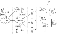
- FIG. 2 shows a communication system 70 including the first slice to the fourth slice.
- the first slices are the vehicles 82 and 84 equipped with the in-vehicle devices 92 and 94 capable of 5G wireless communication, the infrastructure camera 88 equipped with the wireless communication device 98, and the radio provided in the traffic light. It is a slice defined to include a traffic signal controller 90 provided with a communication device 100, a mobile phone 96 included in a pedestrian 86, and the like, and to enable direct communication between them.
- the second slice is a slice that includes a plurality of base stations 110, 112, and 114, and is defined so that the communication terminals included in the first slice communicate with each other.
- the third slice includes metro NWs 120 and 122 and edge servers 126 and 128 provided in distributed DCs (Data Centers) 124 and 130 connected to them, and each communication terminal is a base station. Slices defined to be able to communicate with them via 110, 112, 114, etc.
- the metro NW is a communication network constructed to connect buildings, social facilities, houses, etc. within a limited range such as for each city.
- the base stations 110, 112, 114 and the like are connected to any of the edge servers such as the edge servers 126 and 128, respectively.
- Edge servers 126, 128, etc. are so called because they are located on the outermost side of the system connected by the network and are servers connecting the network system and the rest.
- the fourth slice includes the core NW140 capable of communicating with a plurality of metro networks, and the core server 144 provided in the core DC 142 connected to the core NW140 is the edge server 126, 128, etc., and each metro network. It is possible to communicate with the communication device connected to.
- the above-mentioned traffic condition bird's-eye view map is constructed and maintained for a specific range on the edge server 128 or the like.
- Each communication terminal belonging to the first slice transmits sensor data or the like detected by the sensors provided therein to, for example, the edge server 126.
- the edge server 126 reconstructs the actual road conditions in the virtual space by integrating the sensor data, and creates and maintains the traffic condition bird's-eye view map 52.
- the edge server 126 transmits information for supporting the operation or the like to each communication terminal based on the traffic condition bird's-eye view map 52 maintained in this way.
- the in-vehicle / outside cooperation device is an in-vehicle network for data transfer, a wireless communication device that wirelessly communicates data with the outside of the vehicle, and an in-vehicle / outside cooperation device used in a vehicle equipped with a plurality of sensors.
- the transmission delay of the sensor data between the data receiving unit that receives the sensor data from the plurality of sensors via the in-vehicle network and the end from each of the plurality of sensors to a predetermined device that can be communicated by the wireless communication device.
- the end-to-end delay time estimation unit that estimates the time
- the value determination unit that determines the value of the sensor data output by the plurality of sensors based on the vehicle condition and the conditions of the plurality of sensors
- the delay time estimation unit estimate the time.
- a selection unit that selects a part of the sensor data based on the transmission delay time and the value determined by the value determination unit, and transmits a copy of the selected sensor data to a predetermined device via a wireless communication device. And include.
- the in-vehicle / external cooperation method includes an in-vehicle network for data transfer, a wireless communication device that wirelessly communicates data with the outside of the vehicle, and sensors from a plurality of sensors in a vehicle equipped with a plurality of sensors.
- a plurality of steps in which the computer estimates the transmission delay time of sensor data between the ends to a predetermined device that can be communicated by the wireless communication device, and the computer is based on the state of the vehicle and the states of the plurality of sensors.
- the transmission delay time estimated in the step of estimating the transmission delay time by the computer and the value determined by the step of determining the value. A part of the above is selected, and a step of transmitting a copy of the selected sensor data to a predetermined device via a wireless communication device is included.
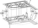
- FIG. 1 is a diagram schematically showing the relationship between the actual road condition and the road condition bird's-eye view map.
- FIG. 2 is a diagram showing a schematic configuration of the communication system shown in Patent Document 1.
- FIG. 3 is a diagram showing a schematic configuration of a traffic support system according to the first embodiment of this disclosure.
- FIG. 4 is a block diagram showing a configuration of elements related to the traffic support system in the vehicle according to the first embodiment of the disclosure.
- FIG. 5 is a block diagram showing a configuration of an edge server, which is a traffic support server that communicates with a vehicle according to the first embodiment of the disclosure.
- FIG. 6 is a block diagram schematically showing a configuration for communication of vehicle sensors and sensor data according to the first embodiment.
- FIG. 7 is a block diagram showing a schematic hardware configuration of an in-vehicle / external cooperation unit used in the vehicle according to the first embodiment shown in FIG.
- FIG. 8 is a diagram showing data required for in-vehicle / out-of-vehicle cooperation stored in the memory in the in-vehicle / out-of-vehicle cooperation unit shown in FIG. 7.
- FIG. 9 is a diagram showing an example of the stored contents of the sensor data set table shown in FIG.
- FIG. 10 is a diagram showing an example of the sensor priority policy table shown in FIG.
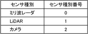
- FIG. 11 is a diagram showing the correspondence between the sensor type and the sensor type number in a table format in the vehicle according to the first embodiment.
- FIG. 12 is a diagram showing the correspondence between the sensor position type indicating the position of the sensor mounted on the vehicle and the sensor position type number in a table format.
- FIG. 13 is a schematic view showing an example of the mounting position of the camera in the vehicle.
- FIG. 14 is a diagram for explaining the priority of the sensor based on the value of the sensor data.
- FIG. 15 is a flowchart showing a control structure of a program for controlling communication from a vehicle, which is executed by the traffic support server according to the first embodiment of the disclosure.
- FIG. 16 is a flowchart showing a control structure of a program for controlling transmission of sensor data, which is executed by an in-vehicle device mounted on a vehicle in the traffic support system according to the first embodiment.
- FIG. 17 is a flowchart showing a control structure of a program for estimating transmission delay, which is executed by an in-vehicle device mounted on a vehicle in the traffic support system according to the first embodiment.
- FIG. 18 is a flowchart showing a control structure of a program for updating the priority policy of the sensor, which is executed by the in-vehicle device mounted on the vehicle in the traffic support system according to the first embodiment.
- FIG. 19 is a flowchart showing a control structure of a program that realizes sensor data selection and switch setting processing executed by an in-vehicle device mounted on a vehicle in the traffic support system according to the first embodiment.
- FIG. 20 is a block diagram showing a schematic configuration of the traffic support system according to the second embodiment of the disclosure.
- FIG. 21 is a block diagram showing the configuration of elements related to the traffic support system in the vehicle according to the second embodiment of the disclosure.
- FIG. 22 is a flowchart showing a control structure of a program for controlling transmission of sensor data, which is executed by an in-vehicle device mounted on a vehicle in the traffic support system according to the second embodiment.
- a traffic situation bird's-eye view map 52 can be constructed and maintained by a communication system as disclosed in Patent Document 1. Dynamic information and caution information regarding traffic obtained from the traffic situation bird's-eye view map 52 are transmitted to each communication terminal. As a result, for example, in a vehicle equipped with such a communication terminal, the road condition can be known when necessary, which can be useful for traffic safety.
- the first issue is how to deal with the dynamic fluctuation of the transmission capacity from the vehicle to the traffic support server such as the edge server.
- the transmission capacity may fluctuate greatly due to 4G / 5G area switching and shadowing.
- the transmission capacity may fluctuate significantly due to changes in the internal state of the vehicle (in-vehicle network, CPU (Central Processing Unit) resource load state), and the state of the traffic support server. Traffic support systems also need to respond appropriately to such dynamic fluctuations in transmission capacity.
- the second issue is the selection of sensor data. When all the sensor data cannot be transmitted from the vehicle to the traffic support server due to the fluctuation of the transmission capacity, it becomes necessary to select and transmit a part of the sensor data. For that purpose, it is necessary to determine what kind of sensor data should be transmitted from the vehicle to the traffic support server for the most efficiency.
- Patent Document 2 described above proposes a technique for switching the type, resolution, and frame rate of an image of a camera mounted on a vehicle according to a change in transmission capacity.
- the state inside the in-vehicle device at the time of performing such control is not taken into consideration.
- what kind of condition sensor should be selected according to various situations in which the vehicle is placed, that is, the value of the sensor data is not considered.
- Patent Document 3 discloses a technique for determining the priority when transmitting a data sample from a vehicle to a server based on the value of the data sample.
- the value of a data sample is calculated based on a data value map in a table called a data value table. Prioritize sending data samples to the server based on the calculated value.
- the data value map is determined based on the purpose of using the data sample in the server, for example, and is transmitted to the vehicle at any time.
- the vehicle receives the data value map, the vehicle updates the existing data value map with the received data. Therefore, from the standpoint of the server, it is possible to collect data from the vehicle with a priority according to the purpose of the data.
- Patent Document 3 does not disclose a technique for changing the method of calculating the value of data in real time based on the situation in which the vehicle is placed.
- the value of data does not change depending on the application, but the priority of data to be transmitted to the server should always be processed in real time according to the vehicle and the surrounding conditions of the vehicle. ..
- Patent Document 3 does not disclose such a technique.
- the purpose of this disclosure is to set the priority of data transmission according to the change in transmission capacity and the situation of the vehicle and its surroundings so that traffic support by a predetermined device such as a traffic support server can be effectively performed. It is to provide an in-vehicle / external cooperation device and a method.
- the vehicle-in-vehicle / external cooperation device is a vehicle used in an in-vehicle network for data transfer, a wireless communication device that wirelessly communicates data with the outside of the vehicle, and a vehicle equipped with a plurality of sensors.
- Sensor data between the data receiving unit which is an internal / external cooperation device and receives sensor data from a plurality of sensors via the in-vehicle network, and the end of each of the plurality of sensors to a predetermined device capable of communicating by a wireless communication device.
- An end-to-end delay time estimation unit that estimates the transmission delay time, a value determination unit that determines the value of sensor data output by a plurality of sensors based on the vehicle condition and the conditions of a plurality of sensors, and a delay time estimation unit. A part of the sensor data is selected based on the transmission delay time estimated by the unit and the value determined by the value determination unit, and a copy of the selected sensor data is transmitted to a predetermined device via a wireless communication device. Includes a selection section to be used.
- the end-to-end delay time estimation unit estimates the transmission delay time of sensor data between the ends from each of a plurality of sensors mounted on the vehicle to a predetermined device.
- the value determination unit determines the value of the sensor data output by the plurality of sensors based on the state of the vehicle and the states of the plurality of sensors.
- the selection unit selects a part of the sensor data based on the transmission delay time estimated by the delay time estimation unit and the value determined by the value determination unit, and makes a copy of the selected sensor data via a wireless communication device. And send it to the specified device. Estimate the transmission delay time between the ends of the sensor to a particular device, including the delay time in the in-vehicle network, and determine based on the estimated transmission delay time and the value determined for each of the sensor data.
- Select the sensor data to send to the device While following the fluctuation of the transmission capacity by the wireless communication device, considering the transmission delay time between the end from the sensor to the predetermined device, select the sensor data that can be effectively used in the predetermined device and cooperate inside and outside the vehicle. Since the device transmits, it is possible to provide an in-vehicle / external cooperation device that can maximize the function of a predetermined device while maximizing the transmission capacity.
- the end-to-end delay time estimation unit includes a network transmission time estimation unit that estimates the network delay time for each sensor until sensor data from a plurality of sensors reaches the data reception unit via the in-vehicle network, and data reception.
- the processing time estimation unit that estimates the processing time required for processing until the sensor data that reaches the unit is input to the wireless communication device, and the wireless communication delay time required for the sensor data to be transmitted from the wireless communication device to a predetermined device.
- the wireless communication delay time estimation unit for estimating the above and the delay time calculation unit for calculating the transmission delay time based on the data amount, network delay time, processing time, and wireless communication delay time of each of the plurality of sensors may be included. ..
- the processing time required for processing the sensor data that has reached the data receiver to be input to the wireless communication device and the wireless communication delay time required for the sensor data to be transmitted from the wireless communication device to a predetermined device is estimated for each sensor, and the transmission delay time between the ends is calculated based on these. Since the transmission delay time between the ends is calculated in consideration of the transmission delay time of the in-vehicle network, the amount of data that can be transmitted to a predetermined device within the allowable delay time can be estimated more accurately, and the sensor data to be transmitted can be selected. You can do it more accurately.
- the value determination unit includes an infrastructure detection range estimation unit that estimates the detection range of infrastructure sensors existing in the vicinity of the vehicle based on the position of the vehicle, and a plurality of sensors based on the position and attitude of the vehicle.
- a value setting unit that estimates the detection range and sets the value of the sensor data from each sensor so that the smaller the area that overlaps with the detection range of the infrastructure sensor estimated by the infrastructure detection range estimation unit, the greater the value. It may be included.
- the sensor data from the sensor with a large detection range that overlaps with the detection range of the infrastructure sensor has low utility value in a predetermined device.
- the sensor data is preferentially selected and transmitted to a predetermined device. Since high-value sensor data is transmitted to a predetermined device within a limited transmission capacity, the predetermined device can perform stable processing based on the sensor data regardless of fluctuations in the transmission capacity.
- the infrastructure detection range estimation unit includes an infrastructure detection range update unit that repeatedly updates the estimated detection range of the infrastructure sensor existing in the vicinity of the vehicle based on the position of the vehicle at predetermined time intervals, and includes a value setting unit. Is the sensor data from each sensor so that the smaller the area that overlaps with the detection range of the infrastructure sensor updated by the infrastructure detection range update unit, the greater the value, based on the position and attitude of the vehicle at predetermined time intervals. It may include a value update unit that repeatedly updates the value of.
- the detection range of the infrastructure sensor is updated at predetermined time intervals.
- the value of the sensor data is also updated at predetermined time intervals based on the position and attitude of the vehicle and the updated detection range of the infrastructure sensor. Therefore, the value of each sensor of the vehicle is updated at least at predetermined time intervals in accordance with the movement of the vehicle and the communication environment around the vehicle.
- high-value sensor data is transmitted to a predetermined device regardless of the movement of the vehicle, changes in the communication environment around the vehicle, and the like. Therefore, regardless of changes in the environment, the predetermined device can perform stable processing.
- Each of the plurality of sensors is classified into one of a plurality of sensor types, and the infrastructure detection range estimation unit determines the detection range of the infrastructure sensors existing in the vicinity of the vehicle based on the position of the vehicle.
- the sensor type detection range estimation unit that estimates for each sensor type of the sensor may be included, and the value setting unit may include the sensor type among the plurality of sensors based on the position and attitude of the vehicle for each of the plurality of sensor types.
- the detection range of each sensor belonging to the It may include a sensor type sensor data value setting unit that sets the value of sensor data from a sensor belonging to the sensor type.
- the value setting unit sets the value of the sensor data for each sensor type, it is possible to select the sensor data that is effective for processing a predetermined device by making more effective use of the transmission capacity.
- the vehicle interior / external cooperation device may further include a sensor data set storage unit that stores information designating a plurality of sensor data sets together with an identifier of each sensor data set, and the plurality of sensor data sets may include a plurality of sensors. For each type, it may include information that specifies the number to be selected from a plurality of sensors and the data format related to the amount of data of the sensor data from the sensor, and the vehicle interior / external cooperation device may further include any of the identifiers from the predetermined device.
- the sensor data set reading unit that reads the sensor data set information corresponding to the identifier from the sensor data set storage unit, and the sensor data set information read by the sensor data set reading unit.
- each of the plurality of sensor types is specified by the information of the sensor data set read by the sensor data set reading unit.
- the sensor data selection unit that selects the sensor data from a certain number of sensors in order from the one with the highest value and the sensor data selected by the sensor data selection unit are transferred with priority over other sensor data. It may include a network setting unit for setting a network.
- the number of sensors specified by the sensor data set is selected in order from the one with the highest value of the sensor data for each sensor type. ..
- a valuable predetermined number of sensor data is transmitted to a predetermined device based on the designation by the sensor dataset. As a result, in the predetermined device, stable processing can be executed by effectively utilizing the sensor data.
- the vehicle is further equipped with a vehicle control device that controls the vehicle using sensor data from a plurality of sensors, and the vehicle control device uses sensor data received from the plurality of sensors via a network.
- a vehicle control device that controls the vehicle using sensor data from a plurality of sensors, and the vehicle control device uses sensor data received from the plurality of sensors via a network.
- An automatic driving ECU Electric Control Unit that automatically drives the vehicle may be included.
- the automatic driving ECU operates based on sensor data from a plurality of sensors mounted on the vehicle. Since any of these sensor data is selected by the vehicle interior / external cooperation device and transmitted to a predetermined device, the sensor data can be shared between the automatic driving ECU and the predetermined device, and the automatic driving of the vehicle and the predetermined device can be efficiently performed. Processing can be executed.
- the vehicle control device is a remote control ECU that controls the vehicle according to a predetermined remote control command, and an external remote control device that receives sensor data received from a plurality of sensors via a network via a wireless communication device. It may include a sensor data transmission unit to be transmitted to the remote control device and an input device for inputting a remote control command received from the remote control device via a wireless communication device to the remote control ECU.
- the remote control device operates based on sensor data received from a plurality of sensors mounted on the vehicle, and transmits a remote control command to the remote control ECU. Any of the sensor data transmitted to the remote control device is selected by the vehicle interior / external cooperation device and transmitted to a predetermined device. Therefore, the sensor data can be shared between the remote control device and the predetermined device, and the remote control of the vehicle and the processing of the predetermined device can be efficiently performed.
- the in-vehicle / external cooperation method includes an in-vehicle network for data transfer, a wireless communication device that wirelessly communicates data with the outside of the vehicle, and a plurality of sensors in a vehicle equipped with a plurality of sensors.
- This is an in-vehicle / out-of-vehicle cooperation method in which the inside and outside of the vehicle are linked by transmitting the sensor data from the computer to a predetermined external device, and the computer receives the sensor data from a plurality of sensors mounted on the vehicle via the in-vehicle network.
- the steps by which the computer estimates the transmission delay time of sensor data between the ends to a predetermined device that can be communicated by the wireless communicator, and the computer's vehicle condition and the condition of multiple sensors Based on the transmission delay time estimated in the step of determining the value of the sensor data output by the plurality of sensors and the step of estimating the transmission delay time by the computer, and the value determined by the step of determining the value. , A step of selecting a part of the sensor data and transmitting a copy of the selected sensor data to a predetermined device via a wireless communication device.
- the transmission delay time of the sensor data between the ends is estimated.
- the value of the sensor data output by the plurality of sensors is determined based on the condition of the vehicle and the condition of the plurality of sensors.
- a portion of the sensor data is selected and a copy of the sensor data is transmitted to a given device via the wireless communicator. ..
- the sensor data to be sent to the device is selected. While following the fluctuation of the transmission capacity due to wireless communication, the sensor data that can be effectively used by the predetermined device is selected and transmitted in consideration of the transmission delay time between the end from the sensor to the predetermined device. It is possible to provide an in-vehicle / external cooperation method that can maximize the functions of a predetermined device while maximizing the transmission capacity.
- the priority of data transmission is determined according to the change in transmission capacity and the situation of the vehicle and its surroundings so that traffic support by a predetermined device such as a traffic support server can be effectively performed. It is possible to provide an in-vehicle / external cooperation device and a method capable of the above.
- FIG. 3 shows a schematic configuration diagram of the traffic support system according to this disclosure.
- this traffic support system like the one described in Patent Document 1, includes vehicles 82 and 84, an infrastructure sensor (not shown), a mobile phone owned by a pedestrian, and the like, and via these and a base station 110. It includes an edge server 128, which is a traffic support server that performs processing for constructing and maintaining a communication status map 152 and a traffic status bird's-eye view map 150.
- the communication status map 152 is, for example, a high-definition map prepared in advance for traffic support divided into a grid consisting of a plurality of compartments having sides of a certain length, and the communication status in each compartment is recorded. ..
- the communication status for each section is represented by the central position of the section and the representative value of the transmission speed of the data transmitted from the vehicle in the section to the traffic support server during a certain period in the past.
- NS In order to calculate the representative value of the transmission speed in the past fixed period, the data related to the transmission speed of the data received by the traffic support server during the past fixed period is also accumulated.
- the representative value of the transmission speed typically, the average transmission speed, the mode value of the transmission speed, the median value of the transmission speed, these representative values calculated from the data excluding the predetermined number of upper and lower parts, etc. are used. be able to.
- a traffic situation bird's-eye view map is a high-definition map prepared in advance in a virtual space for a certain area, and the positions, speeds, attributes, etc. of moving objects such as vehicles and pedestrians and fixed objects such as buildings existing in the area. Is memorized in relation to the identification number.
- the traffic situation bird's-eye view map is obtained from the data transmitted from the so-called infrastructure sensors installed in the area and the in-vehicle sensors mounted on the vehicle, and from predetermined sources regarding road construction, accidents, installation locations of infrastructure sensors and their attributes, etc. It is built on information.
- the first embodiment will be described by taking as an example how the sensor data is transmitted from the vehicle 82 to the edge server 128.
- the vehicle 82 collects sensor data from various sensors 170, an automatic driving ECU (Electronic Control Unit) 172 for automatic driving control of the vehicle, and sensor data from these sensors 170, and communicates with the automatic driving ECU 172.
- the vehicle-mounted device 92 for controlling the automatic driving ECU 172 and the vehicle-mounted communication device 162 used when the vehicle-mounted device 92 communicates with an element outside the vehicle such as an edge server 128 and another vehicle are included.
- the in-vehicle device 92 is connected to the sensor 170 and the automatic driving ECU 172 via the network switch (NSW) 160 for in-vehicle communication to which the sensor 170 and the automatic driving ECU 172 are connected, and to the sensor 170 and the automatic driving ECU 172 via the NSW 160, while the external communication device 162.
- the sensor data from the sensor 170 is transmitted to the outside via the sensor 170, and the operating state of the automatic driving ECU 172 etc. is linked by using the information collected from the sensor etc. in the vehicle and the data received from the outside via the external communication device 162.
- the vehicle interior / external cooperation unit 164 is a process for collecting sensor data and a process for transmitting the sensor data to the outside in response to an instruction from the edge server 128 and a change in the situation of the vehicle 82.
- the in-vehicle device 92 shown in FIG. 4 includes the NSW 160 and the in-vehicle / outside cooperation unit 164, but may be one in-vehicle device including the automatic driving ECU 172 and / or the out-of-vehicle communication device 162.
- the in-vehicle device 92 may be realized as a semiconductor integrated circuit such as an ASIC (Application-Specific Integrated Circuit), a system LSI (Large Scale Integration), or a device in which a plurality of semiconductor integrated circuits are mounted on a substrate.
- ASIC Application-Specific Integrated Circuit
- LSI Large Scale Integration
- the sensor data from the sensor 170 is transmitted to the automatic driving ECU 172, but as shown by the arrow 174, a part of the sensor data is selected by the vehicle interior / external cooperation unit 164 and transmitted to the edge server 128.
- the vehicle-internal / external cooperation unit 164 determines the transmission capacity between the vehicle-external communication device 162 and the edge server 128, the processing time in the network in the vehicle 82, the in-vehicle / external cooperation unit 164 and the like, and the vehicle 82.
- the method of selecting the sensor data that allows the edge server 128 to construct the traffic situation bird's-eye view map 150 most efficiently according to the situation will be described.
- the transmission speed of the in-vehicle network as conventionally used will not be sufficient, and it is being considered to use a network having a gigabit class transmission speed for the in-vehicle network.
- the in-vehicle devices of the vehicle 82 communicate with each other via such a network.
- Existing technologies related to networks connecting computers can be applied to such networks, and it is expected that the cost for constructing an in-vehicle network will be reduced accordingly.
- TCP-IP Transmission Control Protocol-Internet Protocol
- the edge server 128 is a signal from a plurality of infrastructure sensor equipment 180 (including any combination of camera, millimeter wave radar and LiDAR) as described above and a sensor (camera) mounted on the vehicle 82. , LiDAR, and any combination of millimeter-wave radar) includes a reception processing unit 210 for receiving signals from 170.
- Each of the infrastructure sensor equipment 180 communicates with the infrastructure sensor 190, which is composed of an arbitrary combination of a camera, a millimeter-wave radar, and LiDAR, for transmitting a signal output by the infrastructure sensor 190 to a reception processing unit 210 of the edge server 128. Includes device 192 and.
- the vehicle 82 also includes a sensor 170 composed of a camera, LiDAR or millimeter wave radar, and an out-of-vehicle communication device 162 that transmits at least a part of the signal output by the sensor 170 to the reception processing unit 210 of the edge server 128. ..
- the edge server 128 further determines, tracks, and tracks the position of each moving object in a predetermined first cycle by analyzing the ranging signals from LiDAR, millimeter-wave radar, and the like among the signals received by the receiving processing unit 210.
- Includes an attribute detection unit 216 that determines the attributes and positions of moving objects such as vehicles and people in the image in a predetermined second cycle longer than the first cycle by performing the analysis.
- the edge server 128 further includes an attribute storage unit 218 for storing the attribute 217 output by the attribute detection unit 216, a moving object tracking result 213 stored in the moving object tracking result storage unit 214, and an attribute stored in the attribute storage unit 218.
- 217 is repeatedly integrated in a cycle shorter than the second cycle, and the integrated processing unit 224 that outputs the traffic condition bird's-eye view map 225, which is the analysis result after the integration, and the traffic condition bird's-eye view map 225 output by the integrated processing unit 224 are accumulated. Includes a traffic situation bird's-eye view map storage unit 226 to be stored.
- the moving object tracking result 213, the attribute 217, and the traffic condition bird's-eye view map 225 are calculated at predetermined times, respectively, but the analysis results calculated in the past fixed time are also recorded as the history of the moving object tracking result storage unit 214, the attribute storage unit 218, and the attribute storage unit 218, respectively. It is stored and stored in the traffic situation bird's-eye view map storage unit 226.
- the integrated processing unit 224 performs the integrated processing
- the history of the traffic condition bird's-eye view map 225 which is the past integrated analysis result accumulated in the traffic condition bird's-eye view map storage unit 226, may be referred to.
- the edge server 128 further obtains vehicle information including vehicle attributes such as identification information of the vehicle to be managed, mounted sensor information, position, speed, and vehicle size based on the signal received from each vehicle by the reception processing unit 210. It includes a vehicle tracking unit 220 for obtaining and a vehicle information storage unit 222 for storing vehicle information 221 of each vehicle analyzed by the vehicle tracking unit 220.
- vehicle attributes such as identification information of the vehicle to be managed, mounted sensor information, position, speed, and vehicle size based on the signal received from each vehicle by the reception processing unit 210. It includes a vehicle tracking unit 220 for obtaining and a vehicle information storage unit 222 for storing vehicle information 221 of each vehicle analyzed by the vehicle tracking unit 220.
- the edge server 128 further collates the moving object information of the traffic situation bird's-eye view map 225 with the vehicle information 221 stored in the vehicle information storage unit 222, and in the integrated moving object information, a child or a pedestrian walking while looking at a smartphone.
- Information for traffic support such as information on moving objects with attributes that are considered dangerous, accident vehicles on the road, broken vehicles, falling objects, etc., to vehicles located within a predetermined range from the object It includes an information transmission unit 228 that performs processing such as notifying the target vehicle, and a transmission processing unit 230 for transmitting a signal for information notification by the information transmission unit 228 to the target vehicle.
- the edge server 128 further includes a high-definition map storage unit 262 that stores a high-definition map, a traffic situation bird's-eye view map stored in the traffic situation bird's-eye view map storage unit 226, and a high-definition map stored in the high-definition map storage unit 262.
- a high priority area extraction unit 240 for extracting coordinates that specify a high priority area is included.
- the high priority area is an area in which sensor data related to the area needs to be collected preferentially.
- high-priority areas for example, an area in which a number of moving objects exceeding a predetermined threshold value exists in the area, and moving objects having attributes that may cause dangerous behavior such as children are detected. Area etc. can be considered.
- the high priority area extraction unit 240 extracts the high priority area by, for example, dividing the road map into predetermined sections and determining whether or not the above conditions are met for each section. For the detection of areas where moving objects above the threshold value are gathered, multiple areas of interest (for example, intersections) are determined in advance on the road map, and it is inspected whether or not the conditions are satisfied only in those areas. You may do so.
- the edge server 128 further stores the sensor priority policy for each of the sensor priority policy storage unit 242 that stores a plurality of sensor priority policies, which will be described later, and the high priority area extracted by the high priority area extraction unit 240.
- the policy determination unit 244 determines which of the sensor priority policies stored in the unit 242 is applied according to the situation of the extracted area and the area extracted by the high priority area extraction unit 240. It includes a candidate vehicle selection unit 246 that selects a vehicle whose area is included in the detection range of the sensor as a candidate vehicle for sensor data collection. That is, in the high priority area, the edge server 128 collects sensor data from only some vehicles. Some of these vehicles are equipped with high performance sensors and transmitters. By selecting such vehicles and collecting sensor data, the edge server 128 can afford the necessary sensor data even when there are a large number of vehicles in the high priority area and the communication status may deteriorate. Can be collected.
- the sensor priority policy shows a guideline regarding what kind of sensor data is prioritized in the sensor data. For example, assume that a child is detected in an area. Such an area is referred to here as a child detection area. Children, unlike adults, can suddenly move unexpectedly. Therefore, in the child detection area, it is necessary to frequently acquire information about the position of the detected moving object. Therefore, the sensor data from a sensor that can detect the position of a moving object at high speed, such as LiDAR, is prioritized over the sensor data from a sensor that is difficult or takes a long time to detect the position of a moving object, such as a camera. Need to send to edge server 128. On the other hand, consider, for example, an area where an accident vehicle exists on the road.
- an area is called an accident area. Since the accident vehicle normally does not move, it is not necessary to send the position coordinates to the edge server 128 with high frequency. In addition, in order to know the situation of the accident, it is easier for the driver of each vehicle to understand the situation by distributing it to each vehicle in the form of an image like a camera. Therefore, it is better to give priority to the camera over LiDAR in such an area. In this way, the sensor priority policy provides a basic guideline as to what kind of sensor should be preferentially transmitted to the edge server 128 depending on the situation of each area.
- each vehicle transmits sensor data to the edge server 128 except in the high priority area, and at that time, the coordinates for specifying the detection range by the sensor of the vehicle (basic position of the vehicle). (Relative coordinates to) is transmitted as vehicle information.
- a candidate vehicle can be selected by calculating the absolute coordinates of the range that can be detected by the sensor of each vehicle from these coordinates and the coordinates of the basic position of the vehicle, and collating the coordinates with the coordinates of each area.
- the edge server 128 further transmits a sensor priority policy determined by the policy determination unit 244 for each of the candidate vehicles selected by the candidate vehicle selection unit 246, and each vehicle is sent to the edge server 128 according to the sensor priority policy.
- the data set inquiry unit 250 for inquiring the sensor data set table consisting of the sensor data set at the time of transmission, and the sensor data set table obtained from each candidate vehicle for the inquiry by the data set inquiry unit 250 for each vehicle.
- the edge server 128 selects and selects the vehicle that can transmit the most efficient sensor data to create a traffic situation bird's-eye view map.
- a vehicle selection unit 252 that transmits an instruction requesting transmission of sensor data to the vehicle, and an inquiry transmission / reception unit 254 for wireless communication of communication with each vehicle by the data set inquiry unit 250 and the vehicle selection unit 252. include.
- Various criteria can be considered from the designer's point of view regarding the transmission of the most effective sensor data for creating a traffic situation bird's-eye view map. For example, it can be considered that the most important data from the viewpoint of driving assistance of traffic participants, that is, data valuable for accident prevention, is transmitted to the edge server 128 at a sufficient transmission speed for that purpose. .. From another point of view, it can be considered that the sensor data is transmitted to the edge server 128 so that the content of the traffic condition bird's-eye view map can follow the actual change as accurately as possible and at a sufficient speed.
- the edge server 128 further transmits data from each section to the edge server 128 based on sensor data, vehicle information, and the like received by the reception processing unit 210 from the vehicle in each section of the high-definition map.
- High-definition stored in the high-definition map storage unit 262 based on the line speed information storage unit 256 that extracts the line speed information of the above and stores it for a predetermined time and the line speed information stored in the line speed information storage unit 256.
- the communication status map management unit 258 for creating and managing the communication status map showing the communication status
- the communication status map storage for storing the communication status map created by the communication status map management unit 258. Including part 260.
- the communication status map is referred to.
- the inquiry transmission / reception unit 254 may use the same hardware as the reception processing unit 210 and the transmission processing unit 230.
- Whether or not the sensor priority policy is met can be quantitatively determined, but in this embodiment, it is determined in advance using a sensor data set table corresponding to each sensor priority policy as described later.
- the sensor dataset table can be created based on subjective criteria, transmission capacity such as line speed, number of high priority areas that the traffic situation bird's-eye view map is paying attention to, the position of vehicles in that area, and each vehicle.
- Formulate a mathematical formula from various factors such as the capacity of the transmission equipment possessed by the vehicle, the number of moving objects existing in the area, etc., and compare the values obtained by applying these factors to this mathematical formula. You can also. However, in reality, it is realistic to use the method using the sensor data set table described below.
- a sensor data set table is prepared in advance for each vehicle.
- Each vehicle responds to an inquiry from the data set inquiry unit 250 and transmits these sensor data set tables to the data set inquiry unit 250.
- the sensor data set table will be described later with reference to FIG.
- each vehicle or infrastructure sensor may have at least a sensor that detects the position of an object such as LiDAR or a millimeter-wave radar and a sensor that acquires an image such as a camera.
- intersections with many moving objects and areas with children are both extracted as high-priority areas of the same level.
- this disclosure is not limited to such embodiments.
- the intersections, etc. are rather wide areas, and the areas where children are detected are narrow areas, and their characteristics are different. Therefore, only one of them may be extracted. Further, a wide area may be extracted first, and a narrow area may be extracted in the wide area.
- the definition (resolution) differs depending on the product specifications, and the amount of sensor data also differs. Therefore, it is necessary to prepare a sensor data set table that conforms to each sensor priority policy by fully considering the type of the target sensor, the definition of the sensor data, and the transmission interval.
- FIG. 6 schematically shows the sensor arrangement and network configuration of the vehicle 82.
- the vehicle 82 has an in-vehicle network 288 having a gigabit-class transmission speed to which the above-mentioned in-vehicle / external cooperation unit 164 and the automatic driving ECU 172 are connected, and the right front portion, the left front portion, and the right rear portion of the vehicle 82.
- And sensor units 280, 282, 284 and 286 mounted on the left rear, respectively.
- Each of the sensor units 280, 282, 284 and 286 includes a millimeter wave radar, a camera, and LiDAR.
- the vehicle-mounted network 288 is located between four Gigabit class network switches 292, 294, 296 and 298, respectively, to which sensors belonging to the same sensor unit are connected, and two network switches 292 and 294 in front of the vehicle. It includes a first multi-giga switch 300 for bridging and a second multi-giga switch 302 for bridging between the two network switches 296 and 298 at the rear of the vehicle and connected to the first multi-giga switch 300.
- the vehicle interior / external cooperation unit 164 is connected to the network switch 292, and the automatic driving ECU 172 is connected to the network switch 294.
- the TCU (Telematics Control Unit) 290 corresponding to the external communication device 162 shown in FIG. 4 is connected to the network switch 292 together with the internal / external cooperation unit 164.
- the sensor units 280, 282, 284 and 286 are arranged at different positions on the vehicle. Therefore, the value of the sensor data from these sensor units may differ depending on the situation in which the vehicle is placed, as will be described later.
- FIG. 7 shows the hardware configuration of the vehicle interior / external cooperation unit 164.
- the vehicle interior / external coordination unit 164 includes a microprocessor 320.
- the microprocessor 320 includes a bus 342, a CPU 340 connected to the bus 342, a ROM (Read-Only Memory) 344, a RAM (Random Access Memory) 346, a DMAC (Direct Media Access Controller) 348, and an input / output I / F. (Interface) 352, a timer 350 and a DMAC348, a timer 350 and an interrupt controller 354 connected to the input / output I / F 352 and causing an interrupt to the CPU 340 in response to a signal from these.
- ROM Read-Only Memory
- RAM Random Access Memory
- DMAC Direct Media Access Controller
- the interrupt controller 354 periodically causes the CPU 340 to interrupt the timer based on the time taken by the timer 350.
- the interrupt controller 354 also causes an input / output interrupt to the CPU 340 when there is an input / output from the outside of the input / output I / F 352. Further, when the data transfer by the DMAC348 is completed, the interrupt controller 354 causes the CPU 340 to interrupt in response to the signal from the DMAC348.
- FIG. 8 shows a RAM 346 stored in the vehicle interior / external cooperation unit 164 shown in FIG. 4 for vehicle interior / external cooperation. All of these fixed data are stored in the ROM 344 shown in FIG. 7 and loaded into the RAM 346 when the program is executed by the CPU 340. Other data are dynamically generated by the CPU 340 and stored in the RAM 346 when the program is executed.
- the RAM 346 is a sensor data set table 402 that stores a plurality of mounted sensor information 400, which is information about a sensor mounted on the vehicle 82, and a plurality of sensor data sets to be transmitted to the outside by the vehicle 82. , When a sensor data set for transmission to the outside is specified, a plurality of sensor priority policies indicating how to determine the priority for each type of sensor according to the vehicle conditions, etc. are stored.
- Sensor priority policy table 404 high-definition map data 406 for navigation system (not shown) mounted on vehicle 82, vehicle internal / external cooperation unit for transmission from various sensors mounted on vehicle 82 to edge server 128
- the sensor data storage area 408 for temporarily storing the sensor data transmitted to 164 and the sensor data set to be transmitted are determined and the sensor priority is determined, the priority according to the priority is determined.
- the packet priority policy is information for specifying the packet priority that can be set for each switch, the number of queues for each packet priority, the packet transfer frequency for each priority, and the like. Using this, a packet transfer policy for each priority is set for each packet, and information that specifies the priority is stored in the packet header of the sensor data, so that each switch executes transfer processing according to the priority. do.
- FIG. 9 shows an example of the sensor data set table 402 stored in the RAM 346.
- the sensor data set table 402 stores eight sensor data sets represented by identification numbers (IDs) 0 to 7 in the first column in this example.
- IDs identification numbers
- the identification number is defined in this embodiment so that the small amount of data transmitted when each sensor data set is selected is small, and the large amount is large.
- a LiDAR, a millimeter wave radar, and a camera are assumed as sensors.
- the second column of FIG. 9 represents the nature of the data transmitted by each sensor dataset.
- the resolution or compression rate at the time of transmission of the sensor data of the LiDAR, the millimeter wave radar, and the camera is shown in order from the left.
- the image data of the camera is an SD (Standard Definition) image.
- the SD image is an image composed of 720 ⁇ 480 pixels or 720 ⁇ 576 pixels.
- a full HD image is an image composed of 1900 ⁇ 1080 pixels.
- the "HD image” such as the identification numbers 3 and 6 is an image composed of 1280 ⁇ 780 pixels. These images are images obtained from the same camera, and the central portion thereof is common to images of any resolution. That is, the HD image is an image of the central portion of the full HD image, and the SD image is an image of the central portion of the HD image.
- the third column is the data transmission interval (data interval).
- this data interval is also set for each ID and each sensor.
- FIG. 9 for example, it is shown that the LiDAR and the millimeter wave radar transmit the identification number 1 10 times per second, and do not transmit the camera image.
- both the LiDAR and the millimeter-wave radar are supposed to transmit the full HD image three times per second and the camera image three times to the edge server 128, respectively.
- the rightmost column shows how many sensors of each type mounted on the vehicle will transmit data. For example, for identification number 1, it indicates that 4 data are transmitted for both LiDAR and millimeter-wave radar, and that the camera is not used. Regarding the identification number 4, the LiDAR and the millimeter-wave radar both transmit the data of four sensors, while the camera also has four. On the other hand, in the case of the identification number 6, the LiDAR and the millimeter wave radar are the same four, but the camera uses only two.
- the total amount of data to be transmitted can be controlled by specifying the resolution or compression rate of each sensor, the transmission interval, and the number of sensors to be used for each identification number. That is, by specifying the sensor data set ID, the content and total amount of sensor data transmitted from the vehicle to the edge server 128 can be controlled.
- the child detection area and the accident area are mentioned as the nature of the area, but the nature of the area is not limited to these. For example, even adults need to be as careful as children when they are operating smartphones. The same applies when a two-seater or three-seater bicycle is detected. Further, as an example in which the camera image is prioritized, for example, a failed vehicle is stopped in a place where many parked vehicles exist, a place where traffic jams exist for a long time, or a position where the vehicle does not normally stop. Areas (failed vehicle areas) and the like can be mentioned.
- each vehicle transmits the sensor data set table of each vehicle to the edge server 128.
- the edge server 128 refers to the sensor data set table of each vehicle, determines from which vehicle the sensor data set corresponding to which identification number is to be transmitted, and sensors the vehicle. Request the transmission of sensor data by specifying the identification number of the data set.
- the available transmission capacity the delay time of data communication by the network in the own vehicle, the processing time by the CPU installed in the in-vehicle device, the transmission delay to the edge server 128, etc.
- the edge server 128 determines whether or not all of the sensor data sets corresponding to the identification numbers transmitted from the edge server 128 can be transmitted within the allowable delay time. If the judgment is affirmative, transmission of the specified sensor data set is started. If the determination is negative, the edge server 128 is requested to lower the identification number by 1, and the transmission of sensor data is not started. When the vehicle responds to lower the identification number by 1, the edge server 128 selects another vehicle and requests that vehicle to transmit a specific sensor data set. When the transmission of the sensor data set from any vehicle is started, the communication is continued, and if all the vehicles request to lower the identification number by 1, the amount of sensor data to be transferred is reduced and the sensor data is reduced. A value one lower than the number specified earlier is specified as the identification number of the set, and the vehicle selection and the sensor data transmission request are repeated again. Details of this procedure will be described later with reference to FIG.
- FIG. 10 shows an example of the sensor priority policy table 404 defined for the identification number of the sensor data set. What is shown in FIG. 10 corresponds to the identification number 3 or 6 in FIG.
- the number of sensors in the sensor data set of the identification number 3 in FIG. 9 is “4, 4, 2”. That is, there are four millimeter-wave radars and four LiDARs, and two cameras.
- FIG. 10 assuming that there are four millimeter-wave radars # 0, 1, 2 and 3 as the millimeter-wave radar, these are adopted in this order.
- LiDAR and if there are LiDAR # 0, # 1, # 2 and 3, these are adopted in this order.
- the camera it is assumed that there are cameras # 0, # 1, # 2 and 3, and cameras # 2 and 3 are adopted among them. Which camera is adopted from the four cameras in this way is determined based on the value of the sensor data obtained from each camera.
- the millimeter-wave radar, LiDAR, and camera are assigned sensor type numbers 0, 1, and 2, respectively, according to the sensor type.
- sensor position type numbers are assigned according to the sensor position types (front and back, left and right). In the example shown in FIG. 12, 0 is assigned when the sensor position is forward, 1 is assigned when the sensor position is rearward, 0 is assigned when the sensor position is left, and 1 is assigned when the sensor position is right.
- the sensor position is a combination of front and back and left and right. That is, in the case of a camera, as shown in FIG.
- the front left camera 440, the front right camera 442, the rear left camera 444, and the rear right camera 446 of the vehicle 82 have the above-mentioned sensor type numbers and sensor position types.
- the following codes are assigned to each camera.
- This code it is possible to decide which one to select when only two of the four cameras are adopted.
- the method will be described below.
- the following description relates to a method of determining the magnitude of the value of image data obtained from each camera, selecting a code according to the value, and adopting a camera corresponding to the code.
- the detection range of the camera of the vehicle 520 there is little or no overlap between the detection range of the camera of the vehicle 520 and the detection range of the surrounding infrastructure cameras, and if the image data obtained by the camera behind the vehicle 520 is transmitted to the edge server 128, the overlap is very small.
- the utility value is high. Further, since the vehicle 520 is in an area where high-speed communication is possible, an HD image or a full HD image can be used as the image.
- the image behind vehicle 522 is of less value to edge server 128.
- the image in front of the vehicle 522 is of high value to the edge server 128. Since the vehicle 522 is also in an area where high-speed communication is possible, HD images or full HD images can be used.
- the value of the image from the camera that obtains an image that does not overlap with the image obtained by the infrastructure camera is set high, and the value of the image from the camera that does not obtain the image is set low, so that the high value image is obtained.
- each of the vehicles 520, 522, and 524 is equipped with four LiDARs, four millimeter-wave radars, and four cameras as shown in FIG. 6, and which sensor priority policy table 404 shown in FIG. 10 is used. It will be explained below whether to decide.
- the sensor type is represented by the code shown in FIG. 11, and the position (front and back, left and right) of each sensor is represented by the code shown in FIG. These are coded in the order of (sensor type, front / back, left / right). The same applies to sensors other than cameras.
- the rear camera is used regardless of the left or right camera. That is, two cameras out of the four cameras are adopted. Since the vehicle 520 is in an area where high-speed communication is possible, the sensor data set in this case is the identification number “6” shown in FIG. In this case, if the codes of the 12 sensors are sorted in descending order, these 12 sensors are arranged in the following order.
- the lower four of these are millimeter-wave radars, and all of them are adopted in the sensor data set of identification number 6.
- the middle four are LiDAR, and all of them are also adopted.
- the first two "211" and "210" refer to the rear camera of the vehicle 520. Since only two cameras are used in the sensor data set of the identification number 6, the upper two cameras are used, and the other cameras are not used.
- each sensor can be coded, and if the value of the front sensor is high, the code is sorted in ascending order, and if the value of the rear sensor is high, the code is sorted in descending order, so that the desired sensor can be selected.
- the entire code is sorted in ascending or descending order.
- this disclosure is not limited to such embodiments.
- the sensor can be selected based on the defined values for both front and back and left and right.
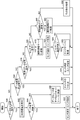
- FIG. 15 shows a control structure of a program in which the edge server 128 requests the specific vehicle in each area to transmit the sensor data and collects the sensor data by a computer in a flowchart format. This program repeatedly operates at predetermined time intervals in parallel with a program for creating a traffic situation bird's-eye view map and a program for creating a communication situation map.
- this program extracts a high priority area from the areas in charge of the edge server 128 according to the above-mentioned criteria, and the following for each area extracted in step 550.
- a period longer than that of a vehicle that transmits sensor data from within the high priority area to a vehicle that does not exist in any of the high priority areas after the step 552 that executes the process 554 and the end of the step 552 ( Includes step 556, which instructs the transmission of the sensor data in (including the case of stopping transmission) and ends the execution of the program.
- the process 554 calculates the detection range of the sensor of the vehicle from the step 570 for determining the sensor priority policy according to the nature of the area to be processed and the data transmitted from the vehicle existing in the area to be processed. , A vehicle that includes the area to be processed in the detection range of the sensor, or a vehicle that is likely to have the area to be processed in the detection range of the sensor in the near future based on the moving speed and direction of the vehicle, and a predetermined sensor is used. Sensor data based on the sensor data set table received from the vehicle according to the sensor priority policy determined in step 570 for each vehicle selected in step 572 and step 572 to select the mounted vehicle as a vehicle candidate.
- step 576 for executing the process 578 for attempting to receive the sensor data for each vehicle, and step 576.
- step 580 in which the determination is made and the control flow is branched according to the determination and the determination in step 580 is negative, the value of the sensor data set identifier to be transmitted to each vehicle is subtracted by 1. Includes step 582, which returns control to step 576.
- the process 578 transmits the identifier of the sensor data set determined in step 574 for the target vehicle, and requests the target vehicle to transmit the corresponding sensor data set.
- step 592 which determines whether or not, and branches the control flow according to the determination, and the determination in step 592 is affirmative, the sensor data is sent to other vehicles existing in the high priority area being processed. It includes step 594 of transmitting an instruction to stop transmission and step 596 of exiting the loop process of process 578 regarding the high priority area being processed.
- the determination in step 592 is negative (a request is received from the target vehicle to lower the identifier of the sensor data set by 1), the process 578 is terminated and the next vehicle among the candidate vehicles in the high priority area to be processed. Processing 578 is started for.
- the process 554 is performed for each area, but there may be a plurality of candidate vehicles in the area.
- Candidate vehicles are sorted, and processing 578 is executed from the vehicle with the highest rank.
- this disclosure is not limited to such methods, for example, selecting vehicles in a random order, or selecting vehicles in the order of longest expected time to be in a high priority area. You can also do it.
- the control proceeds to step 556 and instructs the vehicle existing outside the high priority area to transmit the sensor data in a long cycle. And end the process.
- a predetermined one may be specified, or the identifier is selected on the vehicle side according to the communication speed of the area where each vehicle exists. You may let me.
- Program to realize the in-vehicle and external cooperation unit 164 >> With reference to FIG. 16, the program executed by the computer for realizing the vehicle-in-vehicle / external cooperation unit 164 shown in FIG. 6 is executed when some event is received in the vehicle-in-vehicle / external cooperation unit 164. Here, it is assumed that the event includes an interrupt to the CPU.
- This program includes step 640 of determining whether the received event is a transmission instruction of the sensor data set and branching the control flow according to the determination.
- the transmission instruction of the sensor dataset received in step 640 includes the identifier of any of the sensor datasets in the sensor dataset table of the vehicle equipped with the in-vehicle device running this program.
- the program further reduces the transmission delay required to send the specified sensor data set to the edge server 128 in response to the affirmative decision in step 640, the available wireless transmission capacity, the network in the vehicle.
- step 642 estimated based on the delay, processing by the CPU, etc., and transmission delay estimated in step 642, whether or not the specified sensor data set can be transmitted to the edge server 128, that is, calculated in step 642.
- step 644 which determines whether or not the transmission delay is less than or equal to the allowable delay and branches the control flow according to the determination, and the determination in step 644 is affirmative, the sensor data determined by the specified identifier is used.
- step 650 and step 644 which are set to send to and end the execution of this program, the value of the identifier of the data set to be sent is set by a predetermined number (for example, 1). It includes step 648, which requests the edge server 128 to lower it and ends the execution of the program.
- the program further determines whether the received content is an instruction to stop data transmission from the edge server 128, and branches the control flow.
- each switch in the vehicle network 288 (see FIG. 6) is reset from the state set in step 650 to the default state, and the execution of this program ends. Includes 664 and.
- step 660 the program determines whether the received data is an instruction from the edge server 128 indicating that the sensor data is transmitted at a low speed, and according to the determination.
- step 670 that branches the control flow and the determination in step 670 is affirmative, the sensor data to be transmitted at low speed is reselected, and the transmission of sensor data from the selected sensor is preferentially transferred.
- step 674 sets each switch in the vehicle-mounted network 288 (see FIG. 6) and ends execution of this program.
- the program further determines whether the received data is sensor data from a sensor mounted on the vehicle in response to the negative determination in step 670, and branches the control flow according to the determination.
- the received sensor data is transferred to the automatic operation ECU 172 (see FIG. 6).
- step 683 and step 683 for selecting and setting the switch it is determined whether or not the sensor data received in step 680 is to be transferred to the edge server 128, and the control flow is branched according to the determination result.
- the sensor data received in step 680 is transferred to the edge server 128 to end program execution, and the determinations in steps 686 and 680 are negative.
- it includes a step 688 of performing processing according to the received data and ending the execution of the program.
- the determination in step 684 is negative, the program execution ends without doing anything.
- steps 650, 664 and 674 the presence / absence of transfer of sensor data to the edge server 128 and the transfer speed are confirmed before the transfer of sensor data, and if necessary, the switch of the switch is confirmed according to the confirmation result.
- each sensor data packet from a predetermined sensor is added with information indicating that it should be added to the priority queue of any of the switches set according to the priority policy. Instruct the data output section from the sensor. As a result, whether or not the sensor data should be transmitted, and if so, which sensor data is transmitted, is controlled in almost real time.
- FIG. 17 shows the control structure of the program executed in step 642 of FIG. 16 in a flowchart format.
- this program estimates the delay time between the ends of each sensor data mounted on the vehicle from the sensor that is the output source of the sensor data to the transmission destination (that is, the edge server 128).
- the program further sets the flag indicating whether the sensor data can be transmitted to the edge server 128 within the allowable delay time to 0 in response to the affirmative judgment in step 704, and ends the execution of this program.
- step 706 is included, and step 708 is set to set the flag to 9 and end the execution of this program.
- this flag is 0, it is determined that the sensor data can be transmitted, and if it is 9, it is determined that it is not possible.
- the process 702 of FIG. 17 is a process target in step 730 for confirming (estimating) the transmission capacity (in this case, wireless transmission delay) from the in-vehicle / external cooperation unit 164 to the edge server 128, and in the in-vehicle network 288 shown in FIG. Step 732 to confirm (estimate) the data transmission delay from the sensor to TCU290, and step 734 to confirm (estimate) the system processing time required by the CPU 340 (see FIG. 7) and TCU290 to transmit the sensor data. And, by summing steps 730, 732, and 734, the delay time that occurs in the transmission from the sensor to the edge server 128 is estimated for the sensor data to be processed, and step 736 that ends the process 702 is included.
- the transmission capacity in this case, wireless transmission delay
- the wireless transmission delay that becomes a problem in step 730 is largely due to fluctuations in the transmission capacity of the wireless communication used by the TCU 290 in FIG.
- the transmission capacity of wireless communication may fluctuate greatly due to switching between 4G communication and 5G communication, shadowing by a large vehicle, and the like.
- the observation result when the latest actual data communication is actually executed between the vehicle and the edge server 128 may be used as the transmission delay.
- the transmission delay is calculated by the following formula.
- Wireless transmission delay sensor data volume / line speed + in-vehicle network transmission delay + system processing time + margin
- the in-vehicle network transmission delay and system processing time should be tabulated based on the latest observation results.
- the margin may be set including the in-vehicle network transmission delay and the system processing time.
- the timer 350 shown in FIG. 7 synchronizes with an external time based on a protocol such as NTP (Network Time Protocol), AVB (Audio-Video Bridging), and TSN (Time-Sensitive Networking). Further, the timers of each part in the vehicle are also synchronized with the timer 350 so that the calculation of the transmission delay is not inconvenient.
- NTP Network Time Protocol
- AVB Audio-Video Bridging
- TSN Time-Sensitive Networking
- the transmission delay of the in-vehicle network is the sum of the time it takes for the sensor data from each sensor to arrive at the in-vehicle / outside cooperation unit 164 and the time it takes for the sensor data from the in-vehicle / outside cooperation unit 164 to arrive at the TCU 290 in FIG. Say that.
- the processing time of the CPU means the processing time required for the processing for transmitting the sensor data to the edge server 128 by the CPU 340 shown in FIG. 7. Since the vehicle interior / external cooperation unit 164 controls the vehicle, it is necessary to allow a margin for the vehicle interior control as the resources of the vehicle interior network and the CPU.
- FIG. 18 shows a control structure of a program for realizing a priority policy update process executed by the CPU 340 of the vehicle interior / external cooperation unit 164 shown in FIG. 7 in response to an interrupt signal generated by the timer 350 at predetermined time intervals.
- this program detects the position of the own vehicle from the output of GPS (Global Positioning System) or the like, and the infrastructure sensor equipment existing in the vicinity of the own vehicle from the map information based on the step 800.
- a step 802 for searching for the above, and a step 804 for determining whether or not the infrasensor searched in step 802 is within a predetermined distance in front of the own vehicle and branching the control flow in response to the determination result are included.
- This program further determines whether or not the infrastructure sensor exists within a predetermined distance behind the own vehicle when the determination in step 804 is affirmative, and branches the control flow based on the determination result in step 806. And, when the judgment of step 806 is affirmative, the distance to the front infrastructure sensor and the distance to the rear infrastructure sensor are compared, and it is judged whether or not the front infrastructure sensor is farther, and the judgment is made.
- Step 808 that responds and branches the control flow
- step 812 that determines that the front of the sensors mounted on the own vehicle is prioritized and ends the execution of the program when the judgment of step 808 is affirmative.
- the sensor including the step 810 that determines to give priority to the rear of the sensors mounted on the own vehicle and accommodates the execution of the program.
- the program further responds to a negative decision in step 806 by deciding to prioritize the rear sensor and ending program execution, and in response to a negative decision in step 804. Then, it is determined whether or not the infrastructure sensor exists within a predetermined distance behind the own vehicle, and the step 816 for branching the control flow according to the determination and the determination in step 816 are affirmative. Then, among the sensors mounted on the own vehicle, step 818, which determines that the front sensor is prioritized and ends the execution of the program, and step 816 are executed when the determination of step 816 is negative, and the own vehicle is executed. This includes step 820, which randomly sets the priority of the mounted sensors and ends the execution of the program.
- Execute this program sort the sensor codes in ascending or descending order according to the priority as described above, and select the number of high-priority sensors for each sensor type in the number specified by the sensor data set. Then, the sensor priority policy table 404 for determining the sensor data set to be transmitted to the edge server 128 is obtained. This program is repeated at predetermined time intervals, and the sensor priority policy table 404 is updated each time. Therefore, if this predetermined time is made sufficiently short, an appropriate sensor priority policy table 404 can always be obtained in near real time according to the position of the vehicle and the surrounding conditions.
- FIG. 19 is a flowchart showing a control structure of a program for realizing step 650 of FIG. With reference to FIG. 19, this program performs the following process 852 on each sensor data in the sensor data set specified by the identifier received from the edge server 128 to the edge server 128 for each sensor type.
- step 850 to select the sensor to output the sensor data to be transmitted, and the priority policy of packet transfer corresponding to the priority determined by step 850 is set in each switch (or the output unit of each sensor) of this program. Includes step 854 and the end of execution.
- the process 852 determines whether or not the number of sensors defined in the designated sensor data set is less than the number of sensors of the sensor type to be processed and mounted on the vehicle, and responds to the determination.
- step 872 for determining the value of each sensor by the sensor priority policy table 404 when the determination in step 870 is affirmative, and step 872, the sensor with the highest value is specified first. All the sensors of the sensor type to be processed are selected in response to the negative determination in step 874 and step 870 in which the specified number of sensors are selected for the sensor type to be processed by the sensor data set. Includes step 878 to select and end process 852.
- each sensor included in the sensor units 280, 282, 284 and 286 outputs sensor data according to the surrounding situation. These sensor data are transmitted to the vehicle interior / external cooperation unit 164 via the network switches 292, 294, 296, 298, the first multi-giga switch 300, the second multi-giga switch 302, and the like, respectively.
- LiDAR measures the distance to the lattice points of the parts of moving objects facing LiDAR that exist within a predetermined range around them, and the distance measurement signal is a point that is a set of three-dimensional position coordinates of each point.
- Millimeter-wave radar measures the distance to surrounding moving objects and outputs the signal.
- the camera captures an image in the imaging range at a predetermined frame rate.
- an image (SD image, HD image, full HD image) in a range specified by the sensor data set including the central part of the image is output.
- These sensor data are transmitted to the automatic operation ECU 172 shown in FIG. 6, and among these, the sensor data specified by the sensor data set specified by the edge server 128 is also transmitted to the edge server 128.
- the edge server 128 and the vehicle interior / external cooperation unit 164 operate as follows.
- the timer 350 shown in FIG. 7 generates a timer interrupt at predetermined time intervals and gives an interrupt signal to the CPU 340.
- the CPU 340 executes a program whose control structure is shown in FIG. By executing this program regularly, it is possible to determine the priority when selecting a sensor according to the sensor data set among multiple sensors possessed by the vehicle according to the relationship between the vehicle and the surrounding infrastructure sensors.
- the priority policy is updated in real time.
- the reception processing unit 210 of the edge server 128 receives the signals from the plurality of infrastructure sensor facilities 180 and the signals from the sensors 170 mounted on the vehicle 82, and tracks the signals from the LiDAR and the millimeter-wave radar. It is given to the unit 212, and the image data from the camera is given to the attribute detection unit 216.
- the reception processing unit 210 gives the vehicle tracking unit 220 information indicating the position, speed, and traveling direction of the vehicle among the information received from the sensor 170.
- the vehicle tracking unit 220 maintains data indicating the current position and moving direction of each vehicle based on the received information. From each vehicle, coordinates representing the detection range of the sensor mounted on the vehicle are transmitted to the edge server 128.
- the vehicle information storage unit 222 stores such information together with the coordinates of each vehicle.
- the moving object tracking unit 212 of the edge server 128 determines the position of each moving object in the first cycle by analyzing the distance measurement signal from the LiDAR or the like received from the reception processing unit 210. The time required for this analysis is short, and the moving object tracking result 213 is updated in the first cycle.
- the attribute detection unit 216 determines the attributes of moving objects such as vehicles and people in the image by performing image analysis on the image data received from the reception processing unit 210. Since the image processing takes time, the cycle of attribute detection by the attribute detection unit 216 is a second cycle longer than the update cycle of the moving object tracking result 213 by the moving object tracking unit 212.
- the attribute 217 of the attribute detection unit 216 is stored in the attribute storage unit 218.
- the reception processing unit 210 receives the sensor data and the vehicle data from the infrastructure sensor equipment 180, the vehicle 82, etc. in the target area.
- the moving object tracking unit 212 detects the position of the moving object in the target area from the data and tracks the movement thereof.
- the tracking result is stored in the moving object tracking result storage unit 214.
- the attribute detection unit 216 detects the attribute of each moving object.
- the detected attributes of the moving object are stored in the attribute storage unit 218.
- the integrated processing unit 224 integrates the tracking result of the moving object and the attributes of the moving object, creates a traffic situation bird's-eye view map 225 using the high-definition map stored in the traffic situation bird's-eye view map storage unit 226, and uses the data for traffic. It is saved in the situation bird's-eye view map storage unit 226.
- the integrated processing unit 224 constantly updates the traffic condition bird's-eye view map 225 stored in the traffic condition bird's-eye view map storage unit 226 based on the newly received data.
- the vehicle tracking unit 220 stores the vehicle information 221 received from each vehicle in the vehicle information storage unit 222.
- the vehicle tracking unit 220 further tracks each vehicle in the area based on the vehicle information 221 stored in the vehicle information storage unit 222 and the newly received vehicle information 221.
- the vehicle tracking unit 220 further requests the transmission of the transmission data set table to the vehicle newly entering the area, and receives the received transmission data set table in the sensor data set table storage unit 248.
- the information transmission unit 228 When the information to be transmitted to each vehicle is generated in the traffic condition bird's-eye view map 225, the information transmission unit 228 generates information to be transmitted to each vehicle from the data stored in the traffic condition bird's-eye view map storage unit 226, and the transmission processing unit It is transmitted to each vehicle via 230.
- the positions of are extracted and accumulated as a set.
- the communication status map management unit 258 uses the data stored in the line speed information storage unit 256 and the high-definition map stored in the high-definition map storage unit 262 to divide the map into a grid pattern for each section of the vehicle.
- a communication status map regarding the transmission time between the user and the edge server 128 is created and stored in the communication status map storage unit 260.
- the communication status map management unit 258 always keeps the communication status map storage unit 260 up-to-date based on the latest line speed information stored in the line speed information storage unit 256.
- the high priority area extraction unit 240, the policy determination unit 244, the candidate vehicle selection unit 246, the data set inquiry unit 250, and the vehicle selection unit 252 operate as follows. With reference to FIG. 15, the following processing is repeated at a predetermined time.
- the edge server 128 extracts a high priority area from the area in charge of the edge server 128 according to the above-mentioned criteria (step 550). Subsequently, the process 554 is executed in step 552 for each area extracted in step 550.
- the sensor priority policy is determined according to the nature of the area to be processed (step 570). Subsequently, in step 572, the detection range of the sensor of the vehicle is calculated from the data transmitted from the vehicle existing in the area to be processed, and whether or not the vehicle includes the area to be processed in the detection range of the sensor, and whether or not the vehicle is included in the detection range of the sensor. In the near future, it is determined whether or not the area to be processed is a vehicle that is likely to fall within the detection range of the sensor and is equipped with a predetermined sensor, and a vehicle that satisfies the conditions is selected as a vehicle candidate. In the following step 574, for each vehicle selected in step 572, it should be collected from the vehicle according to the sensor priority policy, communication status map and vehicle information about the sensors mounted on each vehicle determined in step 570. Determine and store sensor data sets.
- processing 578 is executed for each candidate vehicle selected in step 572.
- the processing 578 is executed in order from the vehicle having the most preferable attributes (type, number and performance of mounted sensors, data transmission performance, etc.) among the candidate vehicles.
- the transmission of the sensor data is transmitted to the target vehicle together with the identifier of the sensor data set determined in step 574.
- step 642 is executed, and the transmission delay when transmitting the specified sensor data set to the edge server 128 is estimated.
- This process is as shown in FIG. That is, the wireless transmission delay (step 730), the in-vehicle network transmission delay (step 732), and the system processing time (step 734) are confirmed (estimated) for each sensor data, and based on these, the sensor to be processed is used.
- the total delay time between the ends up to edge server 128 is estimated. If the estimated transmission delay is less than the permissible delay for all sensor data, the flag is set to 0 in step 706. If at least one of the sensor data has an estimated transmission delay value equal to or greater than the allowable delay time, the flag is set to 9 in step 708.
- step 644 If it is determined in step 644 that the transmission delay calculated in step 642 is less than the permissible delay and therefore the specified sensor data set can be transmitted to the edge server 128, the sensor data is sent to the edge server 128 in step 650. Sensors for transmission are selected according to the sensor data set, and each switch is configured to preferentially transfer sensor data from that sensor.
- the process of process 852 is executed for each sensor data in the sensor data set corresponding to the identifier specified by the edge server 128.
- the process 852 first, it is determined whether or not the number of sensors specified by the sensor data set for a certain type of sensor is less than the number of all sensors mounted on the vehicle. If this determination is negative, the sensor of the target type mounted on the vehicle is selected as the sensor that transmits the sensor data to all the edge servers 128 (step 878). If the determination in step 870 is affirmative, then in step 872, the value of each sensor is determined according to the sensor priority policy at that time, and the number determined by the specified sensor data set, starting with the high value sensor in step 874. Up to the sensor of is selected. When the sensors are selected for all the sensor types in this way, each switch is set to preferentially transfer the sensor data from the center selected in step 854.
- the output of sensor data destined for the edge server 128 is started from the selected sensor.
- the CPU 340 (FIG. 7) receives the sensor data
- the sensor data is transferred to the automatic operation ECU 172 in step 682 via the route of step 640 ⁇ step 660 ⁇ step 670 ⁇ step 680 in FIG.
- the sensor data is transferred to the edge server 128 via the route of step 684 ⁇ step 686.
- steps 594 and 596 are executed, and the process of step 576 ends. Since it is determined in the following step 580 that the transmission of the sensor data from the target vehicle is being executed, the processing of the target area is completed, and the processing 554 is executed for the next high priority area.
- step 590 If the transmission delay is equal to or longer than the allowable delay time in the vehicle for which the transfer of the sensor data set is requested in step 590, the following processing is executed.
- processing is performed in the route of step 640 ⁇ step 642 ⁇ step 644. Since the determination in step 644 is negative, the process in step 648 is executed. That is, the vehicle transmits information requesting the edge server 128 to lower the identifier of the sensor data set by one.
- the determination in step 592 is negative (flag ⁇ 0).
- the execution of the process 578 for the target vehicle is completed, and the process 578 is executed for the next vehicle.
- the determination in step 580 is negative, and in step 582, 1 is subtracted from the value of the identifier of the sensor data set of each vehicle.
- the process 578 is repeated for each vehicle using the new identifier. This process is repeated until a vehicle is found that can transmit sensor data.
- step 556 is executed to send the sensor data to the vehicles outside the area in a long cycle. An instruction is sent to indicate.
- step 674 is executed via the route of step 640 ⁇ step 660 ⁇ step 670 in FIG.
- sensor selection, data output from the sensor, and resetting of switches in the network to send a different dataset (often all sensor data) to the edge server 128 over a longer cycle than in step 650. (Reset) is performed.
- sensor data is transmitted to the edge server 128 from vehicles other than the selected vehicle at a long cycle.
- step 664 is executed via the route of step 640 ⁇ step 660 in FIG. That is, step 664 is reset, and all sensor data is excluded from the transfer target to the edge server 128.
- the operation when the data set transmission instruction, the data transmission stop instruction, and the low-speed data transmission instruction are received is as described above.
- the CPU 340 receives the sensor data from the sensor, the sensor data is transferred to the automatic operation ECU 172 (see FIG. 6) in step 682 via the route of step 640 ⁇ step 660 ⁇ step 670 ⁇ step 680, and the following steps 684 and According to 686, if the sensor data is to be transferred to the edge server 128, it is transferred to the edge server 128, otherwise the execution of this program is terminated without doing anything.
- step 680 When it is determined in step 680 that the received data is not sensor data, the control proceeds to step 688, executes the process according to the received data, and ends the process.
- a traffic situation bird's-eye view map according to the sensor priority policy according to the condition of the area. Only the vehicle that can transmit the most effective sensor data to the edge server 128 most efficiently within a predetermined allowable delay transmits the sensor data, and the other vehicles do not transmit the sensor data. The amount of data transmitted to the edge server 128 does not become excessive, and a traffic situation bird's-eye view map can be created and maintained in real time in a timely manner.
- the edge server 128 has a high probability of obtaining the information necessary for creating and maintaining a traffic situation bird's-eye view map from the vehicle selected in consideration of the line speed with the edge server 128 and the cause of the transmission delay in the vehicle. Can be collected. As a result, the risk of congestion of communication between the vehicle and the edge server 128 in the target area can be reduced.
- a sensor priority policy according to the reason for the target is adopted, and a vehicle capable of transmitting sensor data in a form conforming to the sensor priority policy is selected. Therefore, it is possible to send the most necessary data to the edge server 128 according to the traffic condition and create a traffic condition bird's-eye view map that sufficiently reflects the necessary information.
- the transmission delay time of the sensor data between each of the plurality of sensors mounted on the vehicle 82 and the end to the edge server 128 is estimated.
- the state of the vehicle including the position and posture of the vehicle 82, the installation position of the plurality of sensors mounted on the vehicle 82 in the vehicle 82, and the detection of the plurality of sensors.
- the value of the sensor data output by the plurality of sensors mounted on the vehicle 82 is determined based on the overlapping state of the range and the detection range of the infrastructure sensor.
- the process of step 874 of FIG. 19 determines the transmission delay time between the ends estimated in the process 702 of FIG. 17, and the process of FIG.
- a portion of the sensor data is selected and a copy of the sensor data is transmitted to the edge server 128 via the TCU 290 of FIG.
- the transmission delay time between the ends from the sensor to the edge server 128 is estimated, including the delay time in the in-vehicle network, and the estimated transmission delay time and the processing of FIG. 18 and step 874 of FIG. 19 for each of the sensor data are obtained. Select the sensor data to be transmitted to the edge server 128 based on the value determined by.
- the function of the edge server 128 can be exhibited as much as possible while maximizing the available transmission capacity.
- the processing time in the CPU 340 until the sensor data reaching the input / output I / F 352 shown in FIG. 7 is input to the TCU 290 in FIG. 6 and the communication delay time required for the sensor data to be transmitted from the TCU 290 to the edge server 128.
- the network delay time until the sensor data from the plurality of sensors reaches the input / output I / F 352 of FIG. 7 via the in-vehicle network 288 shown in FIG. 6 is estimated for each sensor, and each sensor is estimated based on these.
- the transmission delay time between the end from the sensor to the edge server 128 is calculated.
- the transmission delay time between the ends is calculated in consideration of the transmission delay time of the in-vehicle network 288, the amount of data that can be transmitted to the edge server 128 within the allowable delay time can be estimated more accurately, and the sensor data to be transmitted can be selected. Can be done more accurately.
- the sensor data from the sensor having a large detection range that overlaps with the detection range of the infrastructure sensor has low utility value in the edge server 128.
- the sensor data from these sensors is preferentially selected and transmitted to the edge server 128 by calculating the value of the one having a small overlap range with the sensor and the value of the one having a large overlap range.
- the edge server 128 can perform stable processing based on the sensor data regardless of fluctuations in the transmission capacity.
- the algorithm shown in FIG. 18 does not examine the details of the detection range of the infrastructure sensor, but at least among the sensors mounted on the vehicle 82, it is unlikely or almost that the detection range overlaps with the infrastructure sensor. The above conditions are met in that no sensor is selected.
- the detection range of the infrastructure sensor is updated at predetermined time intervals.
- the value of the sensor data is also updated at predetermined time intervals based on the position and orientation of the vehicle 82 and the updated detection range of the infrastructure sensor as shown in FIG. Therefore, the value of each sensor of the vehicle 82 is updated at least at predetermined time intervals in accordance with the movement of the vehicle 82 and the environment around the vehicle 82.
- high-value sensor data is transmitted to the edge server 128 regardless of the movement of the vehicle 82, changes in the environment around the vehicle, and the like. Therefore, the edge server 128 can perform stable processing regardless of changes in the distribution of vehicles and the environment.
- the value of the sensor data is set for each type of sensor. Therefore, it is possible to select effective sensor data for processing of the edge server 128 by making more effective use of the transmission capacity.
- the sensor data set corresponding to the identifier is determined as shown in FIG.
- the number of sensors specified by the sensor data set is selected for each sensor type in order from the one with the highest value of the sensor data.
- a valuable predetermined number of sensor data is transmitted to the edge server 128 based on the specifications specified by the sensor dataset. As a result, the edge server 128 can effectively utilize the sensor data to execute stable processing.
- the automatic driving ECU 172 shown in FIG. 6 operates based on sensor data from a plurality of sensors mounted on the vehicle 82. Of these sensor data, the sensor data selected by the vehicle interior / external cooperation unit 164 is transmitted to the edge server 128, so that the sensor data can be shared between the automatic driving ECU 172 and the edge server 128, and the automatic driving of the vehicle and the edge server can be efficiently performed. 128 processes can be executed.
- the traffic support system 900 has a vehicle 914 having the same configuration as the vehicle 82 according to the first embodiment, and a vehicle instead of the vehicle 84 of FIG. It has the same configuration as 82, but receives sensor data from the vehicle 916 equipped with a remote control ECU (not shown) and the vehicle 916 via the Internet 912 instead of the automatic driving ECU 172 shown in FIGS. 4 and 6, and this sensor. It includes a remote control server 910 for generating a signal (remote control command) for controlling the remote control ECU of the vehicle 916 based on the data and transmitting the signal (remote control command) to the vehicle 916 via the Internet 912.
- a remote control server 910 for generating a signal (remote control command) for controlling the remote control ECU of the vehicle 916 based on the data and transmitting the signal (remote control command) to the vehicle 916 via the Internet 912.
- the vehicle 916 includes an in-vehicle device 932 in place of the in-vehicle device 92 shown in FIG. 4 and a remote control ECU 930 in place of the automatic driving ECU 172 shown in FIG.
- the in-vehicle device 932 includes an NSW 950, an in-vehicle / out-of-vehicle cooperation unit 952, and an out-of-vehicle communication device 954 in place of the NSW 160 of the in-vehicle device 92, the in-vehicle / out-of-vehicle cooperation unit 164 and the out-of-vehicle communication device 162.
- the remote control ECU 930 does not have an automatic operation function like the automatic operation ECU 172, and in this embodiment, it simply operates according to a remote control command transmitted from the remote control server 910.
- the in-vehicle device 932 does not transmit the sensor data from the sensor 170 to the remote control ECU 930, but as shown by the arrow 960, the NSW950, the in-vehicle / outside cooperation unit 952, and the out-of-vehicle communication device 954. It is transmitted to the remote control server 910 via.
- the remote control command transmitted from the remote control server 910 is received by the vehicle interior / external cooperation unit 952 in the reverse route of the sensor data transmission route, and is given to the remote control ECU 930 via the NSW950.
- FIG. 22 shows a control structure of a program executed by the CPU of the vehicle interior / external cooperation unit 952.
- this program differs from the program shown in FIG. 16 in step 972, which transfers the sensor data to the remote control server 910 when the sensor data is received, instead of step 682 in FIG.
- the point includes step 982 in which the received remote control command is transferred to the remote control ECU 930 shown in FIG. 21 to end the execution of this program.
- the vehicle 916 according to this embodiment is the first except that it is operated by remote control instead of automatic driving. It operates in the same manner as the vehicle 82 according to the embodiment, and the same effect can be obtained.
- the hardware may be the same as that shown in the first embodiment except for the remote control ECU 930, and the difference from the first embodiment is the program executed by the vehicle 916 or the like. It is in the control structure part of.
- the edge server 128 may be exactly the same as that of the first embodiment.
- a vehicle that uses the sensor output for remote control instead of automatic driving can also be used as a target for collecting sensor data. It is possible to broaden the collection target of sensor data, reduce the impact on vehicles with an automatic driving function, and maintain high quality of the traffic condition bird's-eye view map maintained by the edge server.
- the remote control server 910 shown in FIGS. 20 and 21 operates based on the sensor data received from the sensor 170 mounted on the vehicle 916, and transmits a remote control command to the remote control ECU 930. Any of the sensor data transmitted to the remote control server 910 is selected by the vehicle interior / external cooperation unit 952 and transmitted to the edge server 128. Therefore, the sensor data can be shared between the remote control server 910 and the edge server 128, and the vehicle 916 can be remotely controlled and the edge server 128 can be processed efficiently.
- the line speed is measured by the in-vehicle / external cooperation device, and it is determined whether or not the sensor data set can be transmitted.
- the edge server 128 sets the line speed between each vehicle and the edge server 128 estimated from the communication status map 152 (see FIG. 3) and the position of each vehicle in the area managed by the edge server 128. May be sent to.
- the vehicle interior / external cooperation device uses this line speed to determine whether or not the sensor data of the sensor data set can be transmitted.
- the edge server 128 collects the sensor data set table from each vehicle, and requests the candidate vehicle to transmit the sensor data by designating the identifier of the sensor data set based on the table.
- this disclosure is not limited to such embodiments.
- a data set that allows the edge server 128 to transmit the most sensor data from the specified sensor according to conditions such as communication speed to each vehicle without collecting the sensor data set table. It is conceivable to inquire about.
- the edge server 128 may select the vehicle that can transmit the most data among the vehicles that responded.
- the edge server 128 and the vehicle cooperate to determine the sensor data set to be transmitted from the vehicle to the edge server 128.
- the vehicle interior / external cooperation unit 164 may independently determine the sensor data set. For example, when the sensor is a camera, if the image output by the camera becomes unclear, the transmission of the image from that camera to the edge server 128 is stopped, and the image of another camera that can acquire a clear image is obtained. Is considered to be sent to the edge server 128. Whether or not the image is clear may be determined based on whether or not there are many high-frequency components by performing a Fourier analysis on the image, for example.
- time synchronization by the timer shown in FIG. 7 is indispensable.
- the accuracy of time synchronization depends on the protocol used for time synchronization and the hardware performance of the vehicle interior / external cooperation unit 164 and the ECU having a similar configuration. Therefore, when the synchronization error is large, it is desirable to set a large margin in calculating the delay time, and when the synchronization error is small, it is desirable to reduce the margin.
- the computer program for operating the in-vehicle / out-of-vehicle cooperation units 164 and 952 as the functions of the in-vehicle / out-of-vehicle cooperation unit 952 and its components is written in the ROM 344 at the time of shipment of the in-vehicle / out-of-vehicle cooperation units 164 and 952.
- the computer program written to the ROM 344 can be updated via the network.
- these computer programs can be transmitted from a medium such as a CD-ROM (Compact Disk-Read Only Memory) or a DVD-ROM (Digital Amsterdam Disk-Read Only Memory). It can also be updated. In that case, a CD-ROM or DVD-ROM or the like on which a computer program is recorded may be distributed in the market.
Landscapes
- Engineering & Computer Science (AREA)
- Computer Networks & Wireless Communication (AREA)
- Signal Processing (AREA)
- Health & Medical Sciences (AREA)
- Computing Systems (AREA)
- General Health & Medical Sciences (AREA)
- Medical Informatics (AREA)
- Chemical & Material Sciences (AREA)
- Analytical Chemistry (AREA)
- Physics & Mathematics (AREA)
- General Physics & Mathematics (AREA)
- Automation & Control Theory (AREA)
- Human Computer Interaction (AREA)
- Transportation (AREA)
- Mechanical Engineering (AREA)
- Traffic Control Systems (AREA)
Priority Applications (3)
| Application Number | Priority Date | Filing Date | Title |
|---|---|---|---|
| JP2022503149A JP7632449B2 (ja) | 2020-02-27 | 2021-01-18 | 車内外連携装置及び方法 |
| US17/798,571 US12289367B2 (en) | 2020-02-27 | 2021-01-18 | In-vehicle/out-vehicle cooperation device and method |
| CN202180016391.4A CN115151961A (zh) | 2020-02-27 | 2021-01-18 | 车内外协作装置及方法 |
Applications Claiming Priority (2)
| Application Number | Priority Date | Filing Date | Title |
|---|---|---|---|
| JP2020031119 | 2020-02-27 | ||
| JP2020-031119 | 2020-02-27 |
Publications (1)
| Publication Number | Publication Date |
|---|---|
| WO2021171828A1 true WO2021171828A1 (ja) | 2021-09-02 |
Family
ID=77490913
Family Applications (1)
| Application Number | Title | Priority Date | Filing Date |
|---|---|---|---|
| PCT/JP2021/001460 Ceased WO2021171828A1 (ja) | 2020-02-27 | 2021-01-18 | 車内外連携装置及び方法 |
Country Status (4)
| Country | Link |
|---|---|
| US (1) | US12289367B2 (https=) |
| JP (1) | JP7632449B2 (https=) |
| CN (1) | CN115151961A (https=) |
| WO (1) | WO2021171828A1 (https=) |
Cited By (7)
| Publication number | Priority date | Publication date | Assignee | Title |
|---|---|---|---|---|
| CN113866714A (zh) * | 2021-09-23 | 2021-12-31 | 星觅(上海)科技有限公司 | 一种位置确定系统和方法 |
| US11474889B2 (en) * | 2020-06-17 | 2022-10-18 | Denso Corporation | Log transmission controller |
| WO2023074394A1 (ja) * | 2021-10-29 | 2023-05-04 | 住友電気工業株式会社 | 車載装置、路側装置、制御方法およびコンピュータプログラム |
| JPWO2023199850A1 (https=) * | 2022-04-15 | 2023-10-19 | ||
| JP2023178066A (ja) * | 2022-06-03 | 2023-12-14 | ソフトバンク株式会社 | サーバおよび車両 |
| WO2024209664A1 (ja) * | 2023-04-07 | 2024-10-10 | 三菱電機株式会社 | 車載通信装置、車載システム、および車載通信装置のアプリケーション処理方法 |
| WO2024261897A1 (ja) * | 2023-06-21 | 2024-12-26 | 日立Astemo株式会社 | データ収集システム、データ収集サーバ、及びデータ収集方法 |
Families Citing this family (5)
| Publication number | Priority date | Publication date | Assignee | Title |
|---|---|---|---|---|
| JP7671623B2 (ja) * | 2021-05-18 | 2025-05-02 | 株式会社日立製作所 | 制御システム |
| US20240326839A1 (en) * | 2021-10-15 | 2024-10-03 | Sony Group Corporation | Information processing device, information processing method, and program |
| JP7717636B2 (ja) * | 2022-02-15 | 2025-08-04 | 本田技研工業株式会社 | 車載通信システム、および車載通信システムにおける通信制御方法 |
| US20250246071A1 (en) * | 2024-01-31 | 2025-07-31 | Toyota Jidosha Kabushiki Kaisha | Systems and methods for intersection mitigation for vehicles |
| CN120166114B (zh) * | 2025-02-24 | 2025-11-14 | 清华大学 | 一种智能汽车信息物理系统的车云协同数据同步方法 |
Citations (4)
| Publication number | Priority date | Publication date | Assignee | Title |
|---|---|---|---|---|
| WO2010092664A1 (ja) * | 2009-02-10 | 2010-08-19 | トヨタ自動車株式会社 | 車載情報処理装置、情報提供装置及び車両用情報処理システム |
| JP2011022713A (ja) * | 2009-07-14 | 2011-02-03 | Sumitomo Electric Ind Ltd | 通信システム、及び路側通信機 |
| JP2018067864A (ja) * | 2016-10-21 | 2018-04-26 | 株式会社日立製作所 | 通信端末 |
| JP2020095503A (ja) * | 2018-12-13 | 2020-06-18 | 住友電気工業株式会社 | 情報解析装置、情報解析方法、情報解析システム、及びコンピュータプログラム |
Family Cites Families (19)
| Publication number | Priority date | Publication date | Assignee | Title |
|---|---|---|---|---|
| JP4961330B2 (ja) * | 2007-03-20 | 2012-06-27 | 本田技研工業株式会社 | 車両用通信端末装置および通信システム |
| JP5605096B2 (ja) | 2010-09-03 | 2014-10-15 | 富士通株式会社 | ノード装置、時間同期システムおよび時間同期方法 |
| JP5741066B2 (ja) * | 2011-03-01 | 2015-07-01 | 株式会社デンソー | 車両用データ記録装置 |
| JP2012257010A (ja) * | 2011-06-08 | 2012-12-27 | Hitachi Ltd | 通信装置、通信方法及び遠隔監視システム |
| CN102244681A (zh) * | 2011-07-19 | 2011-11-16 | 易程科技股份有限公司 | 传输数据的方法及系统 |
| CN104269058B (zh) * | 2014-09-29 | 2017-01-11 | 中国科学院自动化研究所 | 一种基于无线传感网的智能交通信息采集系统及方法 |
| US10078671B2 (en) * | 2015-02-26 | 2018-09-18 | Red Hat, Inc. | Data hub architecture to provide actionable data from remote sensor feeds |
| US10149192B2 (en) * | 2015-10-21 | 2018-12-04 | Hyundai Motor Company | Vehicle terminal and method for controlling data transmission quantity of the vehicle terminal |
| CN105282031B (zh) * | 2015-11-24 | 2020-04-07 | 腾讯科技(深圳)有限公司 | 一种数据转发方法及装置 |
| JP6888253B2 (ja) | 2016-07-27 | 2021-06-16 | 住友電気工業株式会社 | 無線通信システム、情報取得端末、コンピュータプログラム、及び提供情報の採用可否の判定方法 |
| DE102016214470B4 (de) * | 2016-08-04 | 2023-06-22 | Volkswagen Aktiengesellschaft | Verfahren und System zum Erfassen eines Verkehrsumfeldes einer mobilen Einheit |
| JP6697349B2 (ja) | 2016-08-10 | 2020-05-20 | パナソニック インテレクチュアル プロパティ コーポレーション オブ アメリカPanasonic Intellectual Property Corporation of America | 通信方法およびサーバ |
| JP7013712B2 (ja) * | 2016-10-26 | 2022-02-01 | 株式会社デンソー | データ処理装置、及びデータ処理方法 |
| JP6916609B2 (ja) | 2016-11-21 | 2021-08-11 | パナソニック インテレクチュアル プロパティ コーポレーション オブ アメリカPanasonic Intellectual Property Corporation of America | 交差点情報配信装置及び交差点情報配信方法 |
| CN106961473B (zh) | 2017-03-03 | 2020-07-07 | 上海枫昱能源科技有限公司 | 动态平衡智慧城市网络带宽的高效数据传输方法及系统 |
| US11187793B1 (en) * | 2018-03-02 | 2021-11-30 | Direct Current Capital LLC | Method for temporally calibrating sensor streams in an autonomous vehicle |
| US10797981B2 (en) * | 2018-03-08 | 2020-10-06 | Denso International America, Inc. | Application specific connected service provision system |
| US11099561B1 (en) * | 2018-06-19 | 2021-08-24 | Zoox, Inc. | Control of an autonomous vehicle in unmapped regions |
| US11269066B2 (en) * | 2019-04-17 | 2022-03-08 | Waymo Llc | Multi-sensor synchronization measurement device |
-
2021
- 2021-01-18 CN CN202180016391.4A patent/CN115151961A/zh active Pending
- 2021-01-18 WO PCT/JP2021/001460 patent/WO2021171828A1/ja not_active Ceased
- 2021-01-18 JP JP2022503149A patent/JP7632449B2/ja active Active
- 2021-01-18 US US17/798,571 patent/US12289367B2/en active Active
Patent Citations (4)
| Publication number | Priority date | Publication date | Assignee | Title |
|---|---|---|---|---|
| WO2010092664A1 (ja) * | 2009-02-10 | 2010-08-19 | トヨタ自動車株式会社 | 車載情報処理装置、情報提供装置及び車両用情報処理システム |
| JP2011022713A (ja) * | 2009-07-14 | 2011-02-03 | Sumitomo Electric Ind Ltd | 通信システム、及び路側通信機 |
| JP2018067864A (ja) * | 2016-10-21 | 2018-04-26 | 株式会社日立製作所 | 通信端末 |
| JP2020095503A (ja) * | 2018-12-13 | 2020-06-18 | 住友電気工業株式会社 | 情報解析装置、情報解析方法、情報解析システム、及びコンピュータプログラム |
Cited By (14)
| Publication number | Priority date | Publication date | Assignee | Title |
|---|---|---|---|---|
| US11474889B2 (en) * | 2020-06-17 | 2022-10-18 | Denso Corporation | Log transmission controller |
| CN113866714A (zh) * | 2021-09-23 | 2021-12-31 | 星觅(上海)科技有限公司 | 一种位置确定系统和方法 |
| CN113866714B (zh) * | 2021-09-23 | 2024-11-22 | 星觅(上海)科技有限公司 | 一种位置确定系统和方法 |
| JPWO2023074394A1 (https=) * | 2021-10-29 | 2023-05-04 | ||
| WO2023074394A1 (ja) * | 2021-10-29 | 2023-05-04 | 住友電気工業株式会社 | 車載装置、路側装置、制御方法およびコンピュータプログラム |
| JP7782572B2 (ja) | 2021-10-29 | 2025-12-09 | 住友電気工業株式会社 | 車載装置、路側装置、制御方法およびコンピュータプログラム |
| JPWO2023199850A1 (https=) * | 2022-04-15 | 2023-10-19 | ||
| JP7810790B2 (ja) | 2022-04-15 | 2026-02-03 | 株式会社日立製作所 | 鉄道通信システムおよび鉄道通信方法 |
| JP2023178066A (ja) * | 2022-06-03 | 2023-12-14 | ソフトバンク株式会社 | サーバおよび車両 |
| JP7476257B2 (ja) | 2022-06-03 | 2024-04-30 | ソフトバンク株式会社 | サーバおよび車両 |
| WO2024209664A1 (ja) * | 2023-04-07 | 2024-10-10 | 三菱電機株式会社 | 車載通信装置、車載システム、および車載通信装置のアプリケーション処理方法 |
| JPWO2024209664A1 (https=) * | 2023-04-07 | 2024-10-10 | ||
| JP7774769B2 (ja) | 2023-04-07 | 2025-11-21 | 三菱電機モビリティ株式会社 | 車載通信装置、車載システム、および車載通信装置のアプリケーション処理方法 |
| WO2024261897A1 (ja) * | 2023-06-21 | 2024-12-26 | 日立Astemo株式会社 | データ収集システム、データ収集サーバ、及びデータ収集方法 |
Also Published As
| Publication number | Publication date |
|---|---|
| CN115151961A (zh) | 2022-10-04 |
| US12289367B2 (en) | 2025-04-29 |
| US20230115290A1 (en) | 2023-04-13 |
| JP7632449B2 (ja) | 2025-02-19 |
| JPWO2021171828A1 (https=) | 2021-09-02 |
Similar Documents
| Publication | Publication Date | Title |
|---|---|---|
| WO2021171828A1 (ja) | 車内外連携装置及び方法 | |
| US12422267B2 (en) | Navigation method and apparatus | |
| CN114255606B (zh) | 辅助驾驶提醒、地图辅助驾驶提醒方法、装置和地图 | |
| JP7721620B2 (ja) | 情報送信方法及びクライアント装置 | |
| CN110880236B (zh) | 路况信息处理方法、装置及系统 | |
| JP7031612B2 (ja) | 情報提供システム、サーバ、移動端末、及びコンピュータプログラム | |
| US20190138007A1 (en) | Methods and apparatus to update autonomous vehicle perspectives | |
| CN113498011A (zh) | 车联网方法、装置、设备、存储介质及系统 | |
| CN111866941B (zh) | 一种网络资源调度方法及相关设备 | |
| CN110710264A (zh) | 通信控制装置、通信控制方法和计算机程序 | |
| WO2020111134A1 (ja) | システム、サーバコンピュータ、車載装置、制御方法、半導体集積回路及びコンピュータプログラム | |
| JPWO2020039798A1 (ja) | 情報提供装置、情報提供方法、情報提供システム、コンピュータプログラム、及びデータ構造 | |
| CN115359671A (zh) | 一种路口车辆协同控制方法及相关设备 | |
| JP2023029600A (ja) | 無線通信システム | |
| CN110113716B (zh) | 一种路径状态信息获取方法、装置及存储介质 | |
| WO2019008755A1 (ja) | 情報処理システム及びそれに用いる情報処理システムインフラ及び情報処理方法 | |
| US20220201422A1 (en) | Method, apparatus and computer program product for controlling transmission of sensor data at the edge or near-edge of a network | |
| EP4167606A1 (en) | Cooperative intelligent transport system and method with cpm area perception request | |
| JP6997006B2 (ja) | 車載装置、サーバ、情報システム | |
| JP2024063922A (ja) | 情報処理装置、方法、及びプログラム | |
| US12548383B2 (en) | Dynamic autonomous vehicle modem orchestration | |
| JP7563579B2 (ja) | 路側通信装置、路側通信方法及びプログラム | |
| JP7331399B2 (ja) | センサ設備装置及びその制御方法、車載装置及びその制御方法、並びに交通支援システム | |
| WO2024081624A1 (en) | Dynamic autonomous vehicle modem orchestration | |
| WO2023276435A1 (ja) | 車載装置、サーバ及びシステム |
Legal Events
| Date | Code | Title | Description |
|---|---|---|---|
| 121 | Ep: the epo has been informed by wipo that ep was designated in this application |
Ref document number: 21759884 Country of ref document: EP Kind code of ref document: A1 |
|
| ENP | Entry into the national phase |
Ref document number: 2022503149 Country of ref document: JP Kind code of ref document: A |
|
| NENP | Non-entry into the national phase |
Ref country code: DE |
|
| 122 | Ep: pct application non-entry in european phase |
Ref document number: 21759884 Country of ref document: EP Kind code of ref document: A1 |
|
| WWG | Wipo information: grant in national office |
Ref document number: 17798571 Country of ref document: US |