WO2021171715A1 - 熱交換器の流路構造、及び熱交換器 - Google Patents
熱交換器の流路構造、及び熱交換器 Download PDFInfo
- Publication number
- WO2021171715A1 WO2021171715A1 PCT/JP2020/043467 JP2020043467W WO2021171715A1 WO 2021171715 A1 WO2021171715 A1 WO 2021171715A1 JP 2020043467 W JP2020043467 W JP 2020043467W WO 2021171715 A1 WO2021171715 A1 WO 2021171715A1
- Authority
- WO
- WIPO (PCT)
- Prior art keywords
- heat exchanger
- inner cylinder
- outer cylinder
- flow path
- cylinder
- Prior art date
- Legal status (The legal status is an assumption and is not a legal conclusion. Google has not performed a legal analysis and makes no representation as to the accuracy of the status listed.)
- Ceased
Links
Images




Classifications
-
- F—MECHANICAL ENGINEERING; LIGHTING; HEATING; WEAPONS; BLASTING
- F01—MACHINES OR ENGINES IN GENERAL; ENGINE PLANTS IN GENERAL; STEAM ENGINES
- F01N—GAS-FLOW SILENCERS OR EXHAUST APPARATUS FOR MACHINES OR ENGINES IN GENERAL; GAS-FLOW SILENCERS OR EXHAUST APPARATUS FOR INTERNAL-COMBUSTION ENGINES
- F01N13/00—Exhaust or silencing apparatus characterised by constructional features
- F01N13/08—Other arrangements or adaptations of exhaust conduits
-
- F—MECHANICAL ENGINEERING; LIGHTING; HEATING; WEAPONS; BLASTING
- F01—MACHINES OR ENGINES IN GENERAL; ENGINE PLANTS IN GENERAL; STEAM ENGINES
- F01N—GAS-FLOW SILENCERS OR EXHAUST APPARATUS FOR MACHINES OR ENGINES IN GENERAL; GAS-FLOW SILENCERS OR EXHAUST APPARATUS FOR INTERNAL-COMBUSTION ENGINES
- F01N3/00—Exhaust or silencing apparatus having means for purifying, rendering innocuous, or otherwise treating exhaust
- F01N3/08—Exhaust or silencing apparatus having means for purifying, rendering innocuous, or otherwise treating exhaust for rendering innocuous
- F01N3/10—Exhaust or silencing apparatus having means for purifying, rendering innocuous, or otherwise treating exhaust for rendering innocuous by thermal or catalytic conversion of noxious components of exhaust
- F01N3/24—Exhaust or silencing apparatus having means for purifying, rendering innocuous, or otherwise treating exhaust for rendering innocuous by thermal or catalytic conversion of noxious components of exhaust characterised by constructional aspects of converting apparatus
-
- F—MECHANICAL ENGINEERING; LIGHTING; HEATING; WEAPONS; BLASTING
- F01—MACHINES OR ENGINES IN GENERAL; ENGINE PLANTS IN GENERAL; STEAM ENGINES
- F01N—GAS-FLOW SILENCERS OR EXHAUST APPARATUS FOR MACHINES OR ENGINES IN GENERAL; GAS-FLOW SILENCERS OR EXHAUST APPARATUS FOR INTERNAL-COMBUSTION ENGINES
- F01N5/00—Exhaust or silencing apparatus combined or associated with devices profiting by exhaust energy
- F01N5/02—Exhaust or silencing apparatus combined or associated with devices profiting by exhaust energy the devices using heat
-
- F—MECHANICAL ENGINEERING; LIGHTING; HEATING; WEAPONS; BLASTING
- F28—HEAT EXCHANGE IN GENERAL
- F28D—HEAT-EXCHANGE APPARATUS, NOT PROVIDED FOR IN ANOTHER SUBCLASS, IN WHICH THE HEAT-EXCHANGE MEDIA DO NOT COME INTO DIRECT CONTACT
- F28D1/00—Heat-exchange apparatus having stationary conduit assemblies for one heat-exchange medium only, the media being in contact with different sides of the conduit wall, in which the other heat-exchange medium is a large body of fluid, e.g. domestic or motor car radiators
- F28D1/06—Heat-exchange apparatus having stationary conduit assemblies for one heat-exchange medium only, the media being in contact with different sides of the conduit wall, in which the other heat-exchange medium is a large body of fluid, e.g. domestic or motor car radiators with the heat-exchange conduits forming part of, or being attached to, the tank containing the body of fluid
-
- F—MECHANICAL ENGINEERING; LIGHTING; HEATING; WEAPONS; BLASTING
- F28—HEAT EXCHANGE IN GENERAL
- F28D—HEAT-EXCHANGE APPARATUS, NOT PROVIDED FOR IN ANOTHER SUBCLASS, IN WHICH THE HEAT-EXCHANGE MEDIA DO NOT COME INTO DIRECT CONTACT
- F28D7/00—Heat-exchange apparatus having stationary tubular conduit assemblies for both heat-exchange media, the media being in contact with different sides of a conduit wall
- F28D7/10—Heat-exchange apparatus having stationary tubular conduit assemblies for both heat-exchange media, the media being in contact with different sides of a conduit wall the conduits being arranged one within the other, e.g. concentrically
Definitions
- the present invention relates to a flow path structure of a heat exchanger and a heat exchanger.
- the heat exchanger is a device that exchanges heat between the first fluid and the second fluid by circulating the first fluid inside and the second fluid outside.
- heat can be effectively utilized by exchanging heat from a high-temperature fluid (for example, exhaust gas) to a low-temperature fluid (for example, cooling water).
- a heat collecting portion including a honeycomb structure having a plurality of cells through which a first fluid (for example, exhaust gas) can flow and a heat collecting portion are arranged so as to cover the outer peripheral surface of the heat collecting portion to collect heat.
- Patent Document 2 includes heat including a covering member (inner cylinder) that covers the outer peripheral wall of the columnar honeycomb structure and a frame (outer cylinder) that forms a flow path of a second fluid between the covering member. Exchanges have been proposed.
- the present invention has been made to solve the above problems, and can suppress stagnation around the joints of the supply pipe and the discharge pipe of the second fluid flowing between the first inner cylinder and the outer cylinder. It is an object of the present invention to provide a flow path structure of a heat exchanger and a heat exchanger having the flow path structure.
- the present inventors have adjusted the flow of the second fluid to the joint of the outer cylinder to which at least one of the supply pipe and the discharge pipe is joined. It has been found that the flow of the second fluid around the supply pipe and the discharge pipe can be improved by providing the portion, and the present invention has been completed.
- the first inner cylinder capable of circulating the first fluid and accommodating the heat recovery member and the first inner cylinder
- An outer cylinder arranged at a distance outside in the radial direction of the first inner cylinder so that a second fluid can flow between the first inner cylinder and the outer cylinder.
- the second fluid supply pipe and the discharge pipe joined to the outer cylinder are provided.
- the outer cylinder is a flow path structure of a heat exchanger having a flow adjusting portion for adjusting the flow of the second fluid at at least one joint of the supply pipe and the discharge pipe.
- the present invention is a heat exchanger including a flow path structure of the heat exchanger and a heat recovery member housed in the first inner cylinder.
- a flow path structure of a heat exchanger capable of suppressing stagnation around a joint of a second fluid supply pipe and a discharge pipe flowing between the first inner cylinder and the outer cylinder, and a heat exchanger are provided. Can be provided.
- FIG. 5 is a cross-sectional view parallel to the flow direction of the first fluid of the heat exchanger including the flow path structure of the heat exchanger and the heat recovery member of FIG. It is a perspective view of the flow path structure of the heat exchanger which has another structure which concerns on Embodiment 1 of this invention. It is a perspective view of the flow path structure of the heat exchanger which has another structure which concerns on Embodiment 1 of this invention. It is a perspective view of the flow path structure of the heat exchanger which has another structure which concerns on Embodiment 1 of this invention. It is a perspective view of the flow path structure of the heat exchanger which has another structure which concerns on Embodiment 1 of this invention.
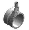
- FIG. 1 is a perspective view of the flow path structure of the heat exchanger according to the first embodiment of the present invention.
- FIG. 2 is a cross-sectional view parallel to the flow direction of the first fluid of the heat exchanger provided with the flow path structure of the heat exchanger of FIG. 1 and the heat recovery member (cross-sectional view of lines AA'in FIG. 1).
- FIGS. 3 to 8 are perspective views of a flow path structure of a heat exchanger having another structure according to the first embodiment of the present invention.
- the outer cylinder 20 arranged at intervals on the radial outer side of the first inner cylinder 10 so that the second fluid can flow, and a second fluid supply pipe 21 and a discharge pipe joined to the outer cylinder 20. 22 and. Further, the outer cylinder 20 has a flow adjusting portion 30 for adjusting the flow of the second fluid at at least one joint portion of the supply pipe 21 and the discharge pipe 22.
- the first inner cylinder 10 and the outer cylinder 20 are connected by the upstream side connecting member 50 and the downstream side connecting member 60, but the upstream side and the downstream side of the first inner cylinder 10 are connected.
- the first inner cylinder 10 and the outer cylinder 20 may be directly connected by increasing the diameter and / or reducing the diameter of the upstream side and the downstream side of the outer cylinder 20.
- the heat exchanger according to the first embodiment of the present invention includes the above-mentioned flow path structure of the heat exchanger and the heat recovery member 40 housed in the first inner cylinder 10.
- FIGS. 1 to 8 show an example in which the flow adjusting portion 30 is provided at the joint portion of both the supply pipe 21 and the discharge pipe 22, one of the joint portion of the supply pipe 21 or the discharge pipe 22 is provided.
- the flow adjusting unit 30 may be provided.
- the supply pipe 21 and the discharge pipe 22 are directly joined to the outer cylinder 20, the second fluid stagnates and boils around the joint portion of the supply pipe 21 and the discharge pipe 22. Therefore, the following problems (1) to (3) may occur.
- the structure of the flow adjusting unit 30 is not particularly limited as long as it can adjust the flow of the second fluid, but as shown in FIGS. 1 and 3 to 8, a part of the outer cylinder 20 in the outer peripheral direction. It is preferable to have a structure that is provided in the outer cylinder 20 and extends outward in the radial direction of the outer cylinder 20. With such a structure, the stagnation of the second fluid around the joint between the supply pipe 21 and the discharge pipe 22 can be stably suppressed.
- the flow adjusting unit 30 has at least one plane region 31 and a joint portion of the supply pipe 21 and / or the discharge pipe 22 is provided in the plane region 31 (FIGS. 1 and 3 to 8). With such a configuration, the supply pipe 21 and / or the discharge pipe 22 can be easily joined to the flow adjusting unit 30.
- the plane region 31 preferably includes a first plane region 31a parallel to the tangent plane of the outer peripheral surface of the outer cylinder 20 and / or a second plane region 31b perpendicular to the axial direction of the outer cylinder 20 (FIGS. 1 and 3 to 3). 8).
- the supply pipe 21 and / or the discharge pipe 22 can be joined in a direction perpendicular to and / or parallel to the axial direction of the outer cylinder 20.
- the outer cylinder 20 preferably has a flow adjusting portion 30 at the joint portion of both the supply pipe 21 and the discharge pipe 22 (FIGS. 1 and 3 to 8). With such a configuration, the stagnation of the second fluid around the joints of both the supply pipe 21 and the discharge pipe 22 is suppressed, so that the flow adjusting unit is connected to one of the joints of the supply pipe 21 and the discharge pipe 22.
- the heat exchange performance can be improved as compared with the case of having 30.
- the joints of both the supply pipe 21 and the discharge pipe 22 can be provided in the first plane region 31a of the flow adjusting portion 30 parallel to the tangent plane of the outer peripheral surface of the outer cylinder 20 (FIGS. 1 and 3 to 6). With such a configuration, when the connection destinations of the supply pipe 21 and the discharge pipe 22 are located in the direction perpendicular to the axial direction of the outer cylinder 20, the directions of the supply pipe 21 and the discharge pipe 22 (particularly, The axial direction at the joint between the supply pipe 21 and the discharge pipe 22) can be directed in that direction.
- both the supply pipe 21 and the discharge pipe 22 are provided in the first plane region 31a of the flow adjusting portion 30 parallel to the tangent plane of the outer peripheral surface of the outer cylinder 20, both the supply pipe 21 and the discharge pipe 22 are joined.
- the portions are preferably located on the same plane (FIGS. 1 and 4). With such a configuration, the axial direction at the joint portion of the supply pipe 21 and the discharge pipe 22 can be made the same direction.
- the supply pipe 21 is provided on the second end surface 23b side of the outer cylinder 20 and the discharge pipe 22 is provided on the first end surface 23a of the outer cylinder 20. It is preferable that the joint portion of the supply pipe 21 and the joint portion of the discharge pipe 22 provided on the side are located diagonally on the same plane (FIG. 4). With such a configuration, the axial direction at the joint portion of the supply pipe 21 and the discharge pipe 22 becomes a direction perpendicular to the axial direction of the outer cylinder 20. Further, the flow of the second fluid flowing between the first inner cylinder 10 and the outer cylinder 20 can be smoothed.
- the joints of both the supply pipe 21 and the discharge pipe 22 can be provided in the second plane region 31b of the flow adjusting portion 30 perpendicular to the axial direction of the outer cylinder 20 (FIG. 8).
- the axial direction at the joint between the supply pipe 21 and the discharge pipe 22 can be made parallel to the axial direction of the outer cylinder 20. Therefore, when the connection destinations of the supply pipe 21 and the discharge pipe 22 are located in a direction parallel to the axial direction of the outer cylinder 20, the directions of the supply pipe 21 and the discharge pipe 22 (particularly, the supply pipe 21 and the discharge pipe 22). (Axial direction at the joint of) can be directed in that direction.
- One of the joints of the supply pipe 21 and the discharge pipe 22 is provided in the first plane region 31a of the flow adjusting portion 30 parallel to the tangent plane of the outer peripheral surface of the outer cylinder 20, and of the supply pipe 21 and the discharge pipe 22.
- the other joint portion can be provided in the second plane region 31b of the flow adjusting portion 30 perpendicular to the axial direction of the outer cylinder 20 (FIG. 7).
- the axial direction at the joint portion of one of the supply pipe 21 and the discharge pipe 22 is set to be perpendicular to the axial direction of the outer cylinder 20, and of the supply pipe 21 and the discharge pipe 22.
- the axial direction at the other joint portion of the outer cylinder 20 can be made parallel to the axial direction of the outer cylinder 20.
- connection destinations of the supply pipe 21 and the discharge pipe 22 when one of the connection destinations of the supply pipe 21 and the discharge pipe 22 is located in a direction parallel to the axial direction of the outer cylinder 20, and the other connection destination is located in a direction perpendicular to the axial direction of the outer cylinder 20.
- the direction of the supply pipe 21 and the discharge pipe 22 (particularly, the axial direction at the joint between the supply pipe 21 and the discharge pipe 22) can be directed to the direction.
- the first inner cylinder 10 is a tubular member arranged on the outer peripheral surface of the heat recovery member 40 in the axial direction (flow direction of the first fluid).
- the shape of the first inner cylinder 10 is not particularly limited, and the cross section perpendicular to the axial direction is a circular cylinder, the cross section is a square cylinder such as a triangle, a quadrangle, a pentagon, or a hexagon, and the cross section is an ellipse. It can be in the shape of an elliptical cylinder.
- the first inner cylinder 10 is preferably cylindrical.
- the inner peripheral surface of the first inner cylinder 10 may be in direct contact with or indirectly in contact with the axial outer peripheral surface of the heat recovery member 40, but from the viewpoint of thermal conductivity, the heat recovery member 40 It is preferable that it is in direct contact with the outer peripheral surface in the axial direction.
- the cross-sectional shape of the inner peripheral surface of the first inner cylinder 10 matches the cross-sectional shape of the outer peripheral surface of the heat recovery member 40.
- the axial direction of the first inner cylinder 10 coincides with the axial direction of the heat recovery member 40, and the central axis of the first inner cylinder 10 coincides with the central axis of the heat recovery member 40.
- the axial length of the first inner cylinder 10 is preferably set longer than the axial length of the heat recovery member 40. Further, it is preferable that the central position of the first inner cylinder 10 coincides with the central position of the heat recovery member 40 in the axial direction of the first inner cylinder 10.
- the diameter (outer diameter and inner diameter) of the first inner cylinder 10 is not particularly limited, but it is preferable that both ends in the axial direction are enlarged. With such a configuration, it can be directly joined to the outer cylinder 20. Further, when the inner cylinder is provided between the first inner cylinder 10 and the outer cylinder 20, the inner cylinder can be directly provided on the outer peripheral surface of the first inner cylinder 10 having an enlarged diameter in the axial direction.
- the diameter (outer diameter and inner diameter) of the first inner cylinder 10 may be uniform over the entire axial direction, or both ends in the axial direction may be reduced in diameter. In this case, spacers may be provided at both ends of the inner cylinder in the axial direction to hold the inner cylinder in the first inner cylinder 10.
- the first inner cylinder 10 is formed of a material having excellent thermal conductivity. Is preferable.
- the material used for the first inner cylinder 10 for example, metal, ceramics, or the like can be used. Examples of the metal include stainless steel, titanium alloy, copper alloy, aluminum alloy, brass and the like.
- the material of the first inner cylinder 10 is preferably stainless steel because of its high durability and reliability.
- the outer cylinder 20 is a tubular member arranged at intervals on the outer side in the radial direction of the first inner cylinder 10.
- the shape of the outer cylinder 20 is not particularly limited, and is a cylinder having a circular cross section perpendicular to the axial direction, a square cylinder having a cross section such as a triangle, a quadrangle, a pentagon, or a hexagon, and an ellipse having an elliptical cross section. It can be tubular or the like.
- the outer cylinder 20 is preferably cylindrical.
- the outer cylinder 20 is preferably arranged coaxially with the first inner cylinder 10.
- the axial direction of the outer cylinder 20 coincides with the axial direction of the heat recovery member 40 and the first inner cylinder 10
- the central axis of the outer cylinder 20 is the center of the heat recovery member 40 and the first inner cylinder 10. It is preferable to coincide with the axis.
- the axial length of the outer cylinder 20 is preferably set longer than the axial length of the heat recovery member 40. Further, it is preferable that the central position of the outer cylinder 20 coincides with the central position of the heat recovery member 40 and the first inner cylinder 10 in the axial direction of the outer cylinder 20.
- the supply pipe 21 and the discharge pipe 22 connected to the outer cylinder 20 are preferably provided at positions corresponding to both ends in the axial direction of the heat recovery member 40. Further, the supply pipe 21 and the discharge pipe 22 may be extended in the same direction or may be extended in different directions.
- the diameter (outer diameter and inner diameter) of the outer cylinder 20 may be uniform over the axial direction, but at least a part (for example, the central portion in the axial direction, both ends in the axial direction, etc.) is reduced or expanded in diameter. May be good.
- the outer cylinder 20 can be directly joined to the first inner cylinder 10, and an inner cylinder is provided between the outer cylinder 20 and the first inner cylinder 10.
- the inner cylinder can be directly provided on the inner peripheral surface of the reduced diameter outer cylinder 20 in the axial direction.
- the second fluid can be distributed in the entire outer cylinder 10 in the outer peripheral direction. Therefore, the amount of the second fluid that does not contribute to heat exchange is reduced in the central portion in the axial direction, so that the heat recovery performance can be improved.
- the material used for the outer cylinder 20 for example, metal, ceramics, or the like can be used.
- the metal include stainless steel, titanium alloy, copper alloy, aluminum alloy, brass and the like.
- the material of the outer cylinder 20 is preferably stainless steel because of its high durability and reliability.
- the upstream side connecting member 50 is a tubular member that connects the upstream side of the first inner cylinder 10 and the upstream side of the outer cylinder 20.
- the downstream side connecting member 60 is a tubular member that connects the downstream side of the first inner cylinder 10 and the downstream side of the outer cylinder 20.
- the upstream side connecting member 50 and the downstream side connecting member 60 are arranged coaxially with the first inner cylinder 10 and the outer cylinder 20 in the axial direction.
- the axial directions of the upstream connecting member 50 and the downstream connecting member 60 coincide with the axial directions of the heat recovery member 40, the first inner cylinder 10 and the outer cylinder 20, and the upstream connecting member 50 and the downstream connecting member 50 and the downstream side.
- the central axis of the connecting member 60 coincides with the central axes of the heat recovery member 40, the first inner cylinder 10 and the outer cylinder 20.
- the upstream side connecting member 50 and the downstream side connecting member 60 have a flange portion for connecting between the first inner cylinder 10 and the outer cylinder 20.
- the shape of the flange portion is not particularly limited, and various known shapes can be used.
- the material used for the upstream side connecting member 50 and the downstream side connecting member 60 is not particularly limited, and the same materials as those exemplified in the first inner cylinder 10 and the outer cylinder 20 can be used.
- the middle cylinder can be provided between the first inner cylinder 10 and the outer cylinder 20 as needed.
- the shape of the middle cylinder is not particularly limited, and is a cylinder having a circular cross section perpendicular to the axial direction, a square cylinder having a cross section such as a triangle, a quadrangle, a pentagon, or a hexagon, and an elliptical cylinder having an elliptical cross section. It can be shaped like a cylinder.
- the inner cylinder is preferably cylindrical.
- the axial direction of the middle cylinder coincides with the axial direction of the heat recovery member 40, and the central axis of the middle cylinder coincides with the central axis of the heat recovery member 40.
- the axial length of the middle cylinder is preferably set longer than the axial length of the heat recovery member 40.
- the central position of the middle cylinder preferably coincides with the central position of the heat recovery member 40, the first inner cylinder 10 and the outer cylinder 20.
- the middle cylinder is arranged between the first inner cylinder 10 and the outer cylinder 20, and the first flow path through which the second fluid can flow between the outer cylinder 20 and the middle cylinder, and the first inner cylinder 10 and the middle cylinder.
- a second flow path through which the second fluid can flow is formed between the cylinder and the cylinder.
- the inner cylinder has a communication hole through which a second fluid can flow between the first flow path and the second flow path. With such a configuration, the second fluid can be circulated in the second flow path.
- the shape of the communication hole is not particularly limited as long as it allows the second fluid to pass through, and may be various shapes such as a circular shape, an elliptical shape, and a polygonal shape.
- a slit may be provided as a communication hole along the axial direction or the circumferential direction of the inner cylinder.
- the number of communication holes is not particularly limited, and there may be a plurality of communication holes in the axial direction of the inner cylinder, and in general, the number of communication holes may be appropriately set according to the shape of the communication holes.
- the heat of the first fluid transferred from the heat recovery member 40 to the first inner cylinder 10 is transferred to the first inner cylinder 10 via the second fluid of the second flow path. It is transmitted to the second fluid in one flow path.
- the second fluid is passed through the second flow path. Heat conduction to the second fluid in one flow path is suppressed. This is because the thermal conductivity of a gaseous fluid is lower than that of a liquid fluid.
- a state in which heat exchange is promoted and a state in which heat exchange is suppressed depending on whether or not a second fluid in a gaseous state is generated in the second flow path.
- This heat exchange state does not require external control. Therefore, by providing the inner cylinder, it is possible to easily switch between promoting and suppressing heat exchange between the first fluid and the second fluid without external control.
- the second fluid a fluid having a boiling point in a temperature range in which heat exchange is desired to be suppressed may be used.
- the heat recovery member 40 is not particularly limited as long as it can recover heat.
- a honeycomb structure can be used as the heat recovery member 40.
- the honeycomb structure is generally a columnar structure.
- the cross-sectional shape perpendicular to the axial direction of the honeycomb structure is not particularly limited, and may be a circle, an ellipse, a square, or another polygon.
- the honeycomb structure has a partition wall and an outer peripheral wall that partition and form a plurality of cells extending from the first end face to the second end face.
- the partition wall and the outer peripheral wall are made of a material containing ceramics as a main component.
- "having ceramics as a main component” means that the mass ratio of ceramics to the mass of all components is 50% by mass or more.
- Each cell penetrates the inside of the honeycomb structure from the first end face to the second end face of the honeycomb structure.
- the first end face and the second end face are end faces on both sides in the axial direction (direction in which the cell extends) of the honeycomb structure.
- each cell (the shape of the cross section perpendicular to the direction in which the cell extends) is not particularly limited, and may be any shape such as a circle, an ellipse, a fan, a triangle, a quadrangle, and a polygon of pentagon or more. can. Further, each cell may be formed radially in a cross section perpendicular to the axial direction of the honeycomb structure. With such a configuration, the heat of the first fluid flowing through the cell can be efficiently transferred toward the outer side in the radial direction of the honeycomb structure.
- the outer peripheral wall of the honeycomb structure is preferably thicker than the partition wall. With such a configuration, the strength of the outer peripheral wall that is easily broken (for example, cracks, cracks, etc.) due to an external impact, thermal stress due to a temperature difference between the first fluid and the second fluid, etc. is increased. Can be done.
- the thickness of the partition wall is not particularly limited and may be adjusted as appropriate according to the application.
- the thickness of the partition wall is preferably 0.1 to 1 mm, more preferably 0.2 to 0.6 mm.
- the thickness of the partition wall is preferably 0.1 to 1 mm, more preferably 0.2 to 0.6 mm.
- the heat exchanger As a method for manufacturing the heat exchanger, it can be manufactured according to a method known in the art.
- the heat exchanger can be manufactured as follows. First, the clay containing the ceramic powder is extruded into a desired shape to prepare a honeycomb molded body.
- the material of the honeycomb structure is not particularly limited, and known materials can be used.
- a binder and water or an organic solvent are added to a predetermined amount of SiC powder, and the obtained mixture is kneaded to form a clay.
- honeycomb molded body having a desired shape can be obtained. Then, the obtained honeycomb molded body is dried, and the honeycomb molded body is impregnated with metallic Si and fired in an inert gas under reduced pressure or in a vacuum. A partitioned honeycomb structure can be obtained. Examples of the method for impregnating and firing metal Si include a method in which the mass 70 containing metal Si and the honeycomb molded body 100 are arranged and fired so as to be in contact with each other, as shown in FIGS. 9 (a) to 9 (l). ..
- the contact point of the mass 70 containing the metal Si in the honeycomb molded body 100 may be the end face or the surface of the outer peripheral wall, and when the honeycomb molded body 100 is a hollow honeycomb molded body, the surface of the inner peripheral wall. It may be. Further, when a plurality of honeycomb molded bodies 100 are laminated and impregnated and fired, as shown in FIGS. 9 (g) and 9 (j), a support member 80 such as a support column or the like is formed between the two honeycomb molded bodies 100 to be laminated. May be provided. Further, as shown in FIGS. 9D and 9F, the two honeycomb molded bodies 100 may be brought into contact with each other without providing the support member 80.
- the metal Si is impregnated by impregnation firing.
- Honeycomb fired bodies can be joined to each other. Further, from the viewpoint of the productivity of the honeycomb molded bodies 100 having various shapes, as shown in FIG. 9 (m), the hollow honeycomb molded body 100a and the solid honeycomb molded body 100b are arranged in the hollow region. Then, the compacts may be arranged so as to be in contact with the mass 70 containing the metal Si, and impregnated and fired.
- the honeycomb structure is inserted into the first inner cylinder 10, and the first inner cylinder 10 is arranged so as to fit into the honeycomb structure by shrink fitting.
- shrink fitting press fitting, brazing, diffusion joining, or the like may be used to fit the honeycomb structure to the first inner cylinder 10.
- the middle cylinder is arranged on the first inner cylinder 10 as needed.
- the first inner cylinder 10 and the middle cylinder may be fixed by welding or the like.
- the structure produced above is placed inside the outer cylinder 20 provided with the flow adjusting portion 30 at the joint portion of the supply pipe 21 and / or the discharge pipe 22, and fixed by welding or the like.
- the method for forming the flow adjusting portion 30 is not particularly limited, and the flow adjusting portion 30 may be separately manufactured and joined to the outer cylinder 20, or the flow adjusting portion 30 is formed by molding the outer cylinder 20. You may.
- the flow of the second fluid is allowed to flow at the joint portion of the outer cylinder 20 to which at least one of the supply pipe 21 and the discharge pipe 22 is joined. Since the flow adjusting unit 30 for adjusting is provided, it is possible to suppress stagnation around the joint portion of the second fluid supply pipe 21 and the discharge pipe 22 flowing between the first inner cylinder 10 and the outer cylinder 20.
- the heat exchanger according to the second embodiment of the present invention includes a flow path structure of the heat exchanger according to the first embodiment of the present invention.
- FIG. 10 is a cross-sectional view parallel to the flow direction of the first fluid of the heat exchanger according to the second embodiment of the present invention.
- components having the same reference numerals as those appearing in the flow path structure of the heat exchanger and the description of the heat exchanger according to the first embodiment of the present invention are described in the second embodiment of the present invention. Since it is the same as the component of the heat exchanger, the description thereof will be omitted.
- the heat exchanger according to the second embodiment of the present invention is arranged as a heat recovery member 40 between the inner peripheral wall, the outer peripheral wall, and the inner peripheral wall and the outer peripheral wall, and extends from the first end surface 201 to the second end surface 202.
- a hollow honeycomb structure 200 having a partition forming a plurality of cells is provided. Further, this heat exchanger has a communication hole 211 that is fitted to the surface of the inner peripheral wall of the hollow honeycomb structure 200 and is provided on the upstream side of the first end surface 201 of the hollow honeycomb structure 200.
- the two inner cylinder 210 and the on-off valve 220 arranged at the downstream end of the second inner cylinder 210 are provided.
- this heat exchanger includes an upstream tubular connecting member 230 connecting between the upstream end side of the first inner cylinder 10 and the upstream end side of the second inner cylinder 210, and the first inner cylinder 10. It is provided with a downstream tubular member 240 connected to the downstream end side of the.
- fitting means that they are fixed in a state of being fitted to each other. Therefore, in the fitting of the hollow honeycomb structure 200 and the second inner cylinder 210, in addition to the fixing method by fitting such as clearance fitting, tight fitting, shrink fitting, brazing, welding, diffusion joining, etc. The case where the hollow honeycomb structure 200 and the second inner cylinder 210 are fixed to each other is also included.
- the heat exchanger having the above structure can switch between promoting and suppressing heat recovery (heat exchange) by opening and closing the on-off valve 220. Specifically, by closing the on-off valve 220, the ventilation resistance of the second inner cylinder 210 increases, and the first fluid selectively flows into the hollow honeycomb structure 200 through the communication hole 211. Therefore, heat recovery (heat exchange) can be promoted. On the other hand, by opening the on-off valve 220, the ventilation resistance of the second inner cylinder 210 is reduced, and the first fluid flows through the second inner cylinder 210 and is discharged to the outside, so that heat recovery (heat exchange) Can be suppressed.
- each component of the heat exchanger according to the second embodiment of the present invention will be described in detail for each component.
- the partition wall, the outer peripheral wall, and the inner peripheral wall constituting the hollow honeycomb structure 200 are generally made of a material containing ceramics as a main component.
- the term "hollow honeycomb structure 200" as used herein refers to a honeycomb structure having a hollow region at the center in a cross section of the hollow honeycomb structure 200 perpendicular to the flow path direction of the first fluid. Means.
- the shape (outer shape) of the hollow honeycomb structure 200 is not particularly limited, and may be, for example, a cylinder, an elliptical pillar, a square pillar, or other polygonal pillar. Further, the shape of the hollow region in the hollow honeycomb structure 200 is not particularly limited, and may be, for example, a cylinder, an elliptical pillar, a square pillar, or other polygonal pillar. The shape of the hollow honeycomb structure 200 and the shape of the hollow region may be the same or different, but they may be the same from the viewpoint of resistance to external impact, thermal stress, and the like. preferable.
- the shape of the cell is not particularly limited, and may be a circle, an ellipse, a triangle, a quadrangle, a hexagon, or another polygon in the cross section in the direction perpendicular to the flow path direction of the first fluid. Further, the cells are preferably provided radially in a cross section in a direction perpendicular to the flow path direction of the first fluid. With such a configuration, the heat of the first fluid flowing through the cell can be efficiently transferred to the outside of the hollow honeycomb structure 200.
- the thickness of the inner peripheral wall and the outer peripheral wall is not particularly limited, but is preferably larger than the thickness of the partition wall. With such a configuration, the inner peripheral wall and the outer peripheral wall are liable to be destroyed (for example, cracks, cracks, etc.) due to an external impact, thermal stress due to a temperature difference between the first fluid and the second fluid, and the like. The strength can be increased.
- the thickness of the inner peripheral wall and the outer peripheral wall is not particularly limited, and may be appropriately adjusted according to the intended use.
- the thickness of the inner peripheral wall and the outer peripheral wall is preferably 0.3 mm to 10 mm, more preferably 0.5 mm to 5 mm, still more preferably 1 mm to 3 mm when the heat exchanger is used for general heat exchange applications. be.
- the heat capacity of the outer peripheral wall may be increased by setting the thickness of the outer peripheral wall to 10 mm or more.
- the catalyst When exhaust gas is flowed through the cell of the hollow honeycomb structure 200 as the first fluid, the catalyst may be supported on the partition wall of the hollow honeycomb structure 200.
- CO, NOx, HC, etc. in the exhaust gas can be made into harmless substances by the catalytic reaction, and the heat of reaction generated during the catalytic reaction can be used for heat exchange. Become.
- precious metals platinum, rhodium, palladium, ruthenium, indium, silver, and gold
- It preferably contains at least one element selected from the group consisting of samarium, bismuth, and barium.
- the above element may be contained as a simple substance of a metal, a metal oxide, or another metal compound.
- the amount of the catalyst (catalyst metal + carrier) supported is not particularly limited, but is preferably 10 to 400 g / L. When a catalyst containing a noble metal is used, the amount of the catalyst supported is not particularly limited, but is preferably 0.1 to 5 g / L.
- the carrier is a carrier on which the catalyst metal is supported. As the carrier, a carrier containing at least one selected from the group consisting of alumina, ceria, and zirconia can be used.
- the second inner cylinder 210 is fitted to the surface of the inner peripheral wall of the hollow honeycomb structure 200.
- the fitting may be either direct or indirect.
- the second inner cylinder 210 and the hollow honeycomb structure 200 may be in direct contact with each other, or may be indirectly in contact with each other via another member (for example, a heat insulating mat). good.
- the second inner cylinder 210 is a tubular member having an upstream side end portion 212 and a downstream side end portion 213. It is preferable that the axial direction of the second inner cylinder 210 coincides with the axial direction of the hollow honeycomb structure 200, and the central axis of the second inner cylinder 210 coincides with the central axis of the hollow honeycomb structure 200.
- the second inner cylinder 210 has a communication hole 211 provided on the upstream side of the first end surface 201 of the hollow honeycomb structure 200.
- the communication hole 211 serves as an inlet for a flow path for introducing the first fluid into the cell of the hollow honeycomb structure 200 when the on-off valve 220 is closed.
- the number of communication holes 211 is not particularly limited, and may be singular or plural. Further, the communication hole 211 may be formed on the entire circumference of the second inner cylinder 210, or may be formed at a partial position (for example, only the upper part, the central part or the lower part) of the communication hole 211. .. Further, the shape of the communication hole 211 can be various shapes such as a circle, an ellipse, and a quadrangle.
- An on-off valve 220 described below is arranged at the downstream end 213 of the second inner cylinder 210.
- the conventional heat exchanger since the flow path cross-sectional area of the second inner cylinder 210 is uniform, when the on-off valve 220 is opened, the high-speed first fluid collides with the shaft 221 that drives the on-off valve 220.
- the pressure loss tends to be large. Since the pressure loss increases as the flow velocity of the first fluid increases, the flow velocity of the first fluid at the position A1 where the on-off valve 220 is arranged may be slowed down in order to reduce the pressure loss.
- the flow path cross-sectional area of the second inner cylinder 210 at the position A1 where the on-off valve 220 is arranged is the second inner cylinder at the position A0 where the communication hole 211 is provided. It is preferably larger than the flow path cross-sectional area of 210.
- the "flow path cross-sectional area of the second inner cylinder 210" refers to the flow path of the first fluid in the direction perpendicular to the flow path direction of the first fluid (axial direction of the second inner cylinder 210). It means the cross-sectional area (inside of the second inner cylinder 210).
- the method of increasing the flow path cross-sectional area of the second inner cylinder 210 at the position A1 to be larger than the flow path cross-sectional area of the second inner cylinder 210 at the position A0 is not particularly limited, but for example, the second inner cylinder 210 at the position A1.
- the inner diameter of the second inner cylinder 210 at position A0 may be larger than the inner diameter of the second inner cylinder 210.
- the tapered portion 214 whose diameter increases toward the downstream end portion 213 may be formed in the second inner cylinder 210.
- the inner diameter of the second inner cylinder 210 at the position A1 is preferably smaller than the inner diameter of the first inner cylinder 10 from the viewpoint of securing the flow path of the first fluid when the on-off valve 220 is closed.
- the material of the second inner cylinder 210 is not particularly limited, and examples thereof include the same materials as those described for the material of the first inner cylinder 10 described above.
- the thickness of the second inner cylinder 210 is not particularly limited, and examples thereof include the same thickness as described for the thickness of the first inner cylinder 10 described above.
- the on-off valve 220 is arranged at the downstream end 213 of the second inner cylinder 210.
- the on-off valve 220 is fixed to the shaft 221 and can be opened and closed by driving (rotating) the shaft 221 by an actuator (not shown).
- the on-off valve 220 is configured so that the flow of the first fluid in the second inner cylinder 210 can be adjusted. Specifically, the on-off valve 220 can be closed when heat recovery is promoted so that the first fluid can flow from the communication hole 211 to the hollow honeycomb structure 200. Further, by opening the on-off valve 220 when heat recovery is suppressed, the first fluid is circulated from the downstream end portion 213 of the second inner cylinder 210 to the downstream tubular member 240 and discharged to the outside of the heat exchanger. can do.
- the shape of the on-off valve 220 is not particularly limited, and an appropriate one may be selected according to the shape of the second inner cylinder 210 on which the on-off valve 220 is provided.
- the upstream-side tubular connecting member 230 has a tubular shape that connects between the upstream end side of the first inner cylinder 10 and the upstream end side of the second inner cylinder 210 so as to form a flow path for the first fluid. It is a member.
- the connection may be either direct or indirect.
- the axial direction of the upstream tubular connecting member 230 coincides with the axial direction of the hollow honeycomb structure 200, and the central axis of the upstream tubular connecting member 230 coincides with the central axis of the hollow honeycomb structure 200. Is preferable.
- the upstream side tubular shape is formed. It is also possible to omit the connecting member 230.
- the material of the upstream side tubular connecting member 230 is not particularly limited, and examples thereof include the same materials as those described for the material of the first inner cylinder 10 described above.
- the thickness of the upstream tubular connecting member 230 is not particularly limited, and examples thereof include the same thickness as described for the thickness of the first inner cylinder 10 described above.
- the downstream tubular member 240 is connected to the downstream end side of the first inner cylinder 10.
- the connection may be either direct or indirect.
- the downstream tubular member 240 has a portion arranged at intervals so as to form a flow path of the first fluid on the radial outer side of the second inner cylinder 210.
- the axial direction of the downstream tubular member 240 may coincide with the axial direction of the hollow honeycomb structure 200, and the central axis of the downstream tubular member 240 may coincide with the central axis of the hollow honeycomb structure 200. preferable. If the downstream end side of the first inner cylinder 10 is stretched to reduce the diameter, the downstream side tubular member 240 can be omitted.
- the diameter (outer diameter and inner diameter) of the downstream tubular member 240 may be uniform over the axial direction, but at least a part of the diameter may be reduced or expanded.
- the material of the downstream tubular member 240 is not particularly limited, and examples thereof include the same materials as those described for the material of the first inner cylinder 10 described above.
- the thickness of the downstream tubular member 240 is not particularly limited, and examples thereof include the same thickness as described for the thickness of the first inner cylinder 10 described above.
- the heat exchanger according to the second embodiment of the present invention can be manufactured according to a method known in the art, similarly to the heat exchanger according to the first embodiment.
- a hollow honeycomb structure 200 is manufactured according to the above-mentioned method for manufacturing a honeycomb structure.
- the hollow honeycomb structure 200 is inserted into the first inner cylinder 10, and the first inner cylinder 10 is arranged so as to fit into the honeycomb structure by shrink fitting.
- the structure produced above is placed inside the outer cylinder 20 provided with the flow adjusting portion 30 at the joint portion of the supply pipe 21 and / or the discharge pipe 22, and fixed by welding or the like.
- the second inner cylinder 210 is fitted to the surface of the inner peripheral wall of the hollow honeycomb structure 200.
- the upstream tubular connecting member 230 is arranged inside the second inner cylinder 210 in the radial direction to connect between the upstream end side of the first inner cylinder 10 and the upstream end side of the second inner cylinder 210. do.
- the on-off valve 220 is attached to the downstream end 213 of the second inner cylinder 210.
- the downstream tubular member 240 is arranged and connected to the downstream end side of the first inner cylinder 10.
- the order of arrangement and fixing (fitting) of each member is not limited to the above, and may be appropriately changed within a manufacturable range. Further, as the fixing (fitting) method, the above-mentioned method may be used.
- the heat exchanger according to the first embodiment of the present invention since the heat exchanger according to the first embodiment of the present invention has a flow path structure, it flows between the first inner cylinder 10 and the outer cylinder 20. It is possible to suppress stagnation around the joint portion of the supply pipe 21 and the discharge pipe 22 of the second fluid. Further, in the heat exchanger according to the second embodiment of the present invention, the inner diameter of the second inner cylinder 210 at the position A1 where the on-off valve 220 is arranged is the inner diameter of the second inner cylinder 210 at the position A0 where the communication hole 211 is provided. Since it is made larger than the above, the pressure loss can also be reduced.
- the heat exchanger according to the second embodiment of the present invention may be configured to include a flow path structure of a conventional heat exchanger instead of the flow path structure of the heat exchanger according to the first embodiment of the present invention.
- a flow path structure of a conventional heat exchanger instead of the flow path structure of the heat exchanger according to the first embodiment of the present invention.
Landscapes
- Engineering & Computer Science (AREA)
- Mechanical Engineering (AREA)
- General Engineering & Computer Science (AREA)
- Chemical & Material Sciences (AREA)
- Combustion & Propulsion (AREA)
- Physics & Mathematics (AREA)
- Thermal Sciences (AREA)
- Chemical Kinetics & Catalysis (AREA)
- Health & Medical Sciences (AREA)
- Toxicology (AREA)
- Heat-Exchange Devices With Radiators And Conduit Assemblies (AREA)
Priority Applications (1)
| Application Number | Priority Date | Filing Date | Title |
|---|---|---|---|
| JP2021522103A JP7146085B2 (ja) | 2020-02-25 | 2020-11-20 | 熱交換器の流路構造、及び熱交換器 |
Applications Claiming Priority (4)
| Application Number | Priority Date | Filing Date | Title |
|---|---|---|---|
| JP2020029798 | 2020-02-25 | ||
| JP2020-029798 | 2020-02-25 | ||
| JP2020-075012 | 2020-04-20 | ||
| JP2020075012 | 2020-04-20 |
Publications (1)
| Publication Number | Publication Date |
|---|---|
| WO2021171715A1 true WO2021171715A1 (ja) | 2021-09-02 |
Family
ID=77491398
Family Applications (1)
| Application Number | Title | Priority Date | Filing Date |
|---|---|---|---|
| PCT/JP2020/043467 Ceased WO2021171715A1 (ja) | 2020-02-25 | 2020-11-20 | 熱交換器の流路構造、及び熱交換器 |
Country Status (2)
| Country | Link |
|---|---|
| JP (1) | JP7146085B2 (https=) |
| WO (1) | WO2021171715A1 (https=) |
Cited By (2)
| Publication number | Priority date | Publication date | Assignee | Title |
|---|---|---|---|---|
| JP2023132252A (ja) * | 2022-03-10 | 2023-09-22 | 日本碍子株式会社 | 流路構造体及び熱交換器 |
| JP2023132253A (ja) * | 2022-03-10 | 2023-09-22 | 日本碍子株式会社 | 熱交換器 |
Citations (6)
| Publication number | Priority date | Publication date | Assignee | Title |
|---|---|---|---|---|
| JPS62156270U (https=) * | 1986-03-26 | 1987-10-03 | ||
| JP2006162238A (ja) * | 2004-11-09 | 2006-06-22 | Denso Corp | 二重管 |
| JP2008069750A (ja) * | 2006-09-15 | 2008-03-27 | Toyota Motor Corp | 排気熱回収装置 |
| JP2012057573A (ja) * | 2010-09-10 | 2012-03-22 | Futaba Industrial Co Ltd | 排気熱回収装置 |
| JP2013053620A (ja) * | 2011-08-10 | 2013-03-21 | Usui Kokusai Sangyo Kaisha Ltd | 多管式熱交換器 |
| WO2019135312A1 (ja) * | 2018-01-05 | 2019-07-11 | 日本碍子株式会社 | 熱交換部材、熱交換器及び浄化手段付き熱交換器 |
-
2020
- 2020-11-20 WO PCT/JP2020/043467 patent/WO2021171715A1/ja not_active Ceased
- 2020-11-20 JP JP2021522103A patent/JP7146085B2/ja active Active
Patent Citations (6)
| Publication number | Priority date | Publication date | Assignee | Title |
|---|---|---|---|---|
| JPS62156270U (https=) * | 1986-03-26 | 1987-10-03 | ||
| JP2006162238A (ja) * | 2004-11-09 | 2006-06-22 | Denso Corp | 二重管 |
| JP2008069750A (ja) * | 2006-09-15 | 2008-03-27 | Toyota Motor Corp | 排気熱回収装置 |
| JP2012057573A (ja) * | 2010-09-10 | 2012-03-22 | Futaba Industrial Co Ltd | 排気熱回収装置 |
| JP2013053620A (ja) * | 2011-08-10 | 2013-03-21 | Usui Kokusai Sangyo Kaisha Ltd | 多管式熱交換器 |
| WO2019135312A1 (ja) * | 2018-01-05 | 2019-07-11 | 日本碍子株式会社 | 熱交換部材、熱交換器及び浄化手段付き熱交換器 |
Cited By (3)
| Publication number | Priority date | Publication date | Assignee | Title |
|---|---|---|---|---|
| JP2023132252A (ja) * | 2022-03-10 | 2023-09-22 | 日本碍子株式会社 | 流路構造体及び熱交換器 |
| JP2023132253A (ja) * | 2022-03-10 | 2023-09-22 | 日本碍子株式会社 | 熱交換器 |
| JP7745485B2 (ja) | 2022-03-10 | 2025-09-29 | 日本碍子株式会社 | 熱交換器 |
Also Published As
| Publication number | Publication date |
|---|---|
| JPWO2021171715A1 (https=) | 2021-09-02 |
| JP7146085B2 (ja) | 2022-10-03 |
Similar Documents
| Publication | Publication Date | Title |
|---|---|---|
| JP7166246B2 (ja) | 熱交換部材、熱交換器及び浄化手段付き熱交換器 | |
| JP7250514B2 (ja) | 熱交換部材及び熱交換器 | |
| WO2021171670A1 (ja) | 熱交換器 | |
| JPWO2017069265A1 (ja) | 排熱回収器 | |
| JP2020159270A (ja) | 熱交換器 | |
| JP7062621B2 (ja) | 熱交換器 | |
| JP7014759B2 (ja) | 熱交換器及びその製造方法 | |
| JP7146085B2 (ja) | 熱交換器の流路構造、及び熱交換器 | |
| JP6793078B2 (ja) | 熱交換器 | |
| US20220333871A1 (en) | Heat exchanger | |
| JP7046039B2 (ja) | 熱交換器 | |
| US20240310124A1 (en) | Honeycomb structure and heat exchanger | |
| JP7745485B2 (ja) | 熱交換器 | |
| JP7744860B2 (ja) | 熱伝導部材の製造方法及び熱交換器 | |
| JP7590887B2 (ja) | 熱交換部材及び熱交換器 | |
| JP7745486B2 (ja) | 熱伝導部材及び熱交換器 | |
| US20240151311A1 (en) | Butterfly valve and heat exhanger | |
| US20240310125A1 (en) | Honeycomb structure for heat exchanger and heat exchanger | |
| JP2022124893A (ja) | 熱交換器 | |
| JP2024088460A (ja) | 熱交換器 | |
| JP2024088457A (ja) | 熱交換器 | |
| JP2022122241A (ja) | 熱交換部材、熱交換器及び熱伝導部材 | |
| JP2022132034A (ja) | 熱交換部材、熱交換器及び熱伝導部材 |
Legal Events
| Date | Code | Title | Description |
|---|---|---|---|
| ENP | Entry into the national phase |
Ref document number: 2021522103 Country of ref document: JP Kind code of ref document: A |
|
| 121 | Ep: the epo has been informed by wipo that ep was designated in this application |
Ref document number: 20921797 Country of ref document: EP Kind code of ref document: A1 |
|
| NENP | Non-entry into the national phase |
Ref country code: DE |
|
| 122 | Ep: pct application non-entry in european phase |
Ref document number: 20921797 Country of ref document: EP Kind code of ref document: A1 |