WO2021171378A1 - Dispositif de séparation, dispositif de détection, dispositif de conservation et capteur - Google Patents
Dispositif de séparation, dispositif de détection, dispositif de conservation et capteur Download PDFInfo
- Publication number
- WO2021171378A1 WO2021171378A1 PCT/JP2020/007516 JP2020007516W WO2021171378A1 WO 2021171378 A1 WO2021171378 A1 WO 2021171378A1 JP 2020007516 W JP2020007516 W JP 2020007516W WO 2021171378 A1 WO2021171378 A1 WO 2021171378A1
- Authority
- WO
- WIPO (PCT)
- Prior art keywords
- plasma
- serum
- hydrophilic
- hydrophilic portion
- separation device
- Prior art date
Links
Images


Classifications
-
- G—PHYSICS
- G01—MEASURING; TESTING
- G01N—INVESTIGATING OR ANALYSING MATERIALS BY DETERMINING THEIR CHEMICAL OR PHYSICAL PROPERTIES
- G01N1/00—Sampling; Preparing specimens for investigation
- G01N1/02—Devices for withdrawing samples
- G01N1/10—Devices for withdrawing samples in the liquid or fluent state
-
- G—PHYSICS
- G01—MEASURING; TESTING
- G01N—INVESTIGATING OR ANALYSING MATERIALS BY DETERMINING THEIR CHEMICAL OR PHYSICAL PROPERTIES
- G01N33/00—Investigating or analysing materials by specific methods not covered by groups G01N1/00 - G01N31/00
- G01N33/48—Biological material, e.g. blood, urine; Haemocytometers
- G01N33/50—Chemical analysis of biological material, e.g. blood, urine; Testing involving biospecific ligand binding methods; Immunological testing
- G01N33/52—Use of compounds or compositions for colorimetric, spectrophotometric or fluorometric investigation, e.g. use of reagent paper and including single- and multilayer analytical elements
Definitions
- the present invention relates to a separation device for separating serum or plasma from a liquid sample containing a sample collected from a living body such as blood, and a detection device, storage device and sensor using the separation device.
- Patent Document 1 has been proposed as a technique for inspecting the presence or absence of a predetermined reactant. Further, as a technique for separating serum or plasma, a technique disclosed in Patent Document 2 has been proposed.
- Patent Document 1 is a method of inspecting the presence or absence of at least one predetermined reactant, and provides a first porous membrane to which a capture analyze that binds to the reactant is bound.
- the step the step of placing the sample to be inspected and the analyze for multiplex detection in a chamber having a bottom formed by the second porous membrane, and the multiplex when at least one of the above reactants is present.
- a method comprising the step of binding the reactant to the capture analyze carried on the first membrane.
- the technique disclosed in Patent Document 2 is a separation filter for separating at least plasma or serum from a liquid containing a sample collected from any of the human body, excrement, and soil, which is laminated on a membrane filter and the above-mentioned membrane filter.
- the separation filter is composed of a hollow fiber or a porous material, and is laminated on a local region on the membrane filter in a plan view, and the separation filter is formed in a plan view with respect to the membrane filter.
- the boundary line of is a separation filter having an arcuate end at least in a plan view.
- an object of the present invention is to provide a technique capable of extracting serum or plasma in a liquid state from a liquid sample. It is in.
- the separation device is a separation device for separating at least serum or plasma from a liquid sample containing a sample collected from a living body or soil, and comprises a hydrophilic portion composed of a hydrophilic material and a hydrophilic portion. It is characterized in that it is provided in a part of the hydrophilic portion and is provided with a separation filter made of a hollow fiber or a porous material.
- the detection device is a detection device for detecting a biological substance, and is a separation device for separating serum or plasma from a liquid sample containing a sample collected from a living body or soil, and the above-mentioned.
- a detection unit for detecting a biological substance from serum or plasma separated from the separation device is provided, and the separation device is provided in a hydrophilic part made of a hydrophilic material and a part of the hydrophilic part, and is hollow. It has a separation filter made of a thread or a porous material, and the detection unit sandwiches the permeation layer provided in the hydrophilic part for permeating the separated serum or plasma and the permeation layer. It is characterized by having a reaction layer for causing a color reaction with the separated serum or plasma, which is provided on the side opposite to the hydrophilic portion.
- the storage device is a storage device for storing serum or plasma, and is a separation device for separating serum or plasma from a liquid sample containing a sample collected from a living body or soil.
- a container capable of accommodating the separation device is provided, and the separation device is provided in a hydrophilic portion made of a hydrophilic material and a part of a region of the hydrophilic portion, and is made of a hollow thread or a porous material.
- the container comprises a separation filter and a storage solution for storing the separated serum or plasma.
- the sensor according to the present invention is a sensor for measuring a biological substance, and is a separation device for separating serum or plasma from a liquid sample containing a sample collected from a living body or soil, and the separation device.
- a measuring unit for measuring a biological substance from serum or plasma separated by It has a separation filter made of a porous material, and the measuring unit is based on a reaction unit for chemically reacting with the separated serum or plasma and a chemical reaction between the serum or plasma and the reaction unit. It is characterized by having a conversion unit that converts generated electrons or light into a signal.
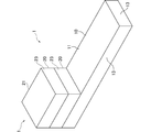
- FIG. 1 is a perspective view showing a first example of the separation device according to the embodiment.
- FIG. 2 is a side view showing a first example of the separation device according to the embodiment.
- FIG. 3 is a diagram for explaining a method of separating serum or plasma from a liquid sample using the first example of the separation device in the embodiment.
- FIG. 4 is a diagram showing a second example of the separation device according to the embodiment.
- 5 (a) is a plan view showing a third example of the separation device according to the embodiment, and
- FIG. 5 (b) is a cross-sectional view taken along the line 5A-5A of FIG. 5 (a).
- FIG. 6A is a cross-sectional view showing a fourth example of the separation device according to the embodiment, and FIG.
- FIG. 6B is a cross-sectional view showing a fifth example of the separation device according to the embodiment.
- FIG. 7 is a diagram showing a sixth example of the separation device according to the embodiment.
- FIG. 8 is a diagram showing a seventh example of the separation device according to the embodiment.
- 9 (a) is a side view showing an eighth example of the separation device 1 in the embodiment, and
- FIG. 9 (b) is a cross-sectional view taken along the line 9A-9A of FIG. 9 (a).
- 10 (a) is a side view showing a ninth example of the separation device 1 in the embodiment, and
- FIG. 10 (b) is a plan view showing the ninth example of the separation device 1 in the embodiment.
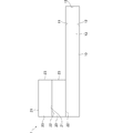
- FIG. 11 is a diagram showing a tenth example of the separation device according to the embodiment.
- FIG. 12 is a diagram for explaining a method of separating serum or plasma from a liquid sample using the tenth example of the separation device in the embodiment.
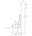
- FIG. 13 is a diagram showing an eleventh example of the separation device according to the embodiment.
- FIG. 14 is a diagram for explaining a method of separating serum or plasma from a liquid sample using the eleventh example of the separation device in the embodiment.
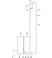
- FIG. 15 is a diagram showing a twelfth example of the separation device according to the embodiment.
- FIG. 16 is a diagram for explaining a method of separating serum or plasma from a liquid sample using the twelfth example of the separation device in the embodiment.
- FIG. 17 is a diagram showing a thirteenth example of the separation device according to the embodiment.
- FIG. 18 is a diagram for explaining a method of separating serum or plasma from a liquid sample using the thirteenth example of the separation device in the embodiment, and FIG. 18 (a) shows the liquid sample. It is a figure which shows the state which injected into the inlet, and FIG. 18 (b) is a figure which shows the state which separated the serum or plasma from the liquid sample.
- FIG. 19 is a diagram showing a first example of the detection device according to the embodiment.
- FIG. 20 is a diagram showing a second example of the detection device according to the embodiment.
- FIG. 21 is a diagram showing a first example of the storage device according to the embodiment.
- FIG. 22 is a diagram for explaining a method of separating serum or plasma from a liquid sample using the separation device of the first example of the storage device in the embodiment.
- FIG. 23 is a diagram for explaining a storage method for storing serum or plasma using the first example of the storage device in the embodiment.
- FIG. 24 is a diagram showing a second example of the storage device according to the embodiment.
- FIG. 25 is a diagram showing a first example of the sensor in the embodiment.
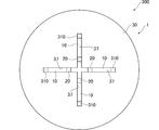
- FIG. 26 is a plan view showing a second example of the sensor in the embodiment.
- FIG. 27 is a plan view showing a third example of the sensor in the embodiment.
- FIG. 28 is a plan view showing a fourth example of the sensor in the embodiment.
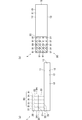
- FIG. 1 is a perspective view showing a first example of the separation device 1 in the embodiment.
- FIG. 2 is a side view showing a first example of the separation device 1 in the embodiment. Further, in each figure, common reference numerals are given to common parts, and duplicate description will be omitted as appropriate.
- the separation device 1 is for separating serum or plasma from a liquid sample containing a sample collected from a living body or soil.
- the sample collected from the living body is, for example, blood.
- the liquid sample is blood.
- the collected material collected from the living body may be mucosal cells such as saliva, tears, sweat, feces, oral mucosal cells, and nasal mucosal cells.
- the liquid sample may be saliva, tears, or sweat.
- a sample such as blood collected from a living body or soil may be dissolved in a solvent in a predetermined container such as a microtube to adjust the pH to prepare a liquid sample.
- the solvent include acetate buffer (acetate + sodium acetate), phosphate buffer (phosphate + sodium phosphate), citrate buffer (citrate + sodium citrate), citrate phosphate buffer (citrate). Acid + sodium phosphate), borate buffer, tartrate buffer, Tris buffer, phosphate buffer physiological saline, McIlvaine buffer, pure water, sucrose PBS buffer, pure water containing surfactant, etc. are used.
- a solvent for example, when collecting urine as a sample from a cancer patient, a diabetic patient, etc., it is preferable to mix a solvent to prepare a liquid sample.
- unnecessary substances such as dust contained in the tears may be removed and then mixed with a solvent to prepare a liquid sample.
- a solvent may be mixed to prepare a liquid sample.
- a solvent may be mixed to remove unnecessary substances such as dietary fiber contained in the stool with a filter paper or the like, and then a liquid sample may be used.
- the separation device 1 includes a hydrophilic portion 10 and a separation filter 20.
- the separation filter 20 includes reagents necessary for the HUDSON method (a method of inactivating ribonuclease contained in a sample of blood or the like by chemical treatment and heating to extract nucleic acid from virus particles or the like), RNase, DNase, or the like. It may contain substances necessary for separating blood cells contained in blood, such as reagents and buffers (pH adjusting materials).
- the hydrophilic portion 10 is formed in a plate shape.
- the hydrophilic portion 10 is made of a hydrophilic material.
- the hydrophilic portion 10 is made of a hydrophilic film, and for example, 9901P manufactured by 3M Japan Ltd. is used.
- the hydrophilic portion 10 may be made of a hydrophilic material by adding a water-repellent surface structure using biomimetics to a base material such as plastic or glass.
- the hydrophilic portion 10 may be made of metal. Hydrophilic paper may be used for the hydrophilic portion 10.
- the hydrophilic portion 10 is an end surface connecting the first main surface 11 on which the separation filter 20 is provided, the second main surface 12 on the opposite side of the first main surface 11, and the first main surface 11 and the second main surface 12. 13 and.
- the separation filter 20 is made of either a hollow fiber or a porous material. Two separation filters 20 are stacked and provided in a part of the hydrophilic portion 10. The separation filter 20 is fixed to the end of the plate-shaped hydrophilic portion 10 in the longitudinal direction. One separation filter 20 may be provided in a part of the hydrophilic portion 10. Two or more separation filters 20 may be stacked in a part of the hydrophilic portion 10.
- the separation filter 20 has a first main surface 21, a second main surface 22 on the opposite side of the first main surface 21, and an end surface 23 connecting the first main surface 21 and the second main surface 22.
- the first main surface 21 is a surface on which a liquid sample is dropped.
- the second main surface 22 is installed in a part of the hydrophilic portion 10.
- Tables 1 and 2 below describe the higher-level concepts of the specific examples. As long as it is included in the superordinate concept, it is not limited to a specific example, and any other material may be applied.
- the separation filter 20 may be added with an anticoagulant or a biological substance.
- the anticoagulant is EDTA (ethylenediaminetetraacetic acid), sodium heparin, citric acid, oxalic acid, sodium fluoride and the like.
- fibrinogen is a substance involved in blood coagulation, which hinders clogging of the detection device and capillarity, makes quantitative measurement difficult, and analysis with a minute blood volume is difficult.
- the following inclusions may be further added to the separation filter 20 in order to remove fibrinogen or prevent coagulation. Thereby, fibrinogen can be absorbed or decomposed, blood coagulation can be prevented, and the test can be facilitated.
- hydrophilic monomers such as polyfunctional acrylamide and sulfobetaine monomers and their fine particles, hydroxyapatite (aquatic phosphoric stone), PEG-based materials (PEG (Polyethylene glycol), PPL-g-PEG copolymer, and PEG. It may contain substances (such as polyethylene glycol).
- PEG Polyethylene glycol
- PPL-g-PEG copolymer PEG. It may contain substances (such as polyethylene glycol).
- metal nanoparticles diameter 5 nm to 500 ⁇ m
- fibrinogen degrading substances fibrinogen degrading substances (fibrinogen), and plasminogen activators (.
- a DNA degrading enzyme inhibitor may be added as an anticoagulant in order to prevent DNA degradation by deoxyribonuclease.
- RNA microRNA, messenger RNA, etc.
- an RNA-degrading enzyme inhibitor is added as an anticoagulant in order to prevent RNA degradation by ribonucleases (endoribonuclease, exoribonuclease, etc.). May be good.
- mucin a protein called mucin, which is a source of viscosity in saliva, may be decomposed, and a mucin-degrading enzyme may be added as an anticoagulant in order to facilitate the measurement.
- FIG. 3 is a diagram for explaining a method of separating serum or plasma from a liquid sample using the first example of the separation device 1 in the embodiment.
- the user collects blood from the subject, and drops a predetermined amount of the collected blood as a liquid sample onto the first main surface 21 of the separation filter 20.
- the dropped blood flows in the separation filter 20 toward the second main surface 22 and the end surface 23 of the separation filter 20 based on the capillary phenomenon in the direction of the arrow M shown in FIG. Become.
- the blood is separated from serum or plasma by flowing through the separation filter 20.
- the hydrophilic part 10 is made of a hydrophilic material.
- the serum or plasma that has reached the hydrophilic portion 10 will flow from the end face 23 onto the hydrophilic portion 10 without being absorbed by the hydrophilic portion 10. Therefore, it is possible to take out serum or plasma in a liquid state.
- Serum or plasma taken out in a liquid state can be collected by a collecting device such as a pipette.
- the hydrophilic portion 10 made of a hydrophilic material and the separation filter 20 provided in a part of the hydrophilic portion 10 and made of a hollow fiber or a porous material are provided. ..
- the serum or plasma flows from the end face 23 of the separation filter 20 onto the hydrophilic portion 10 without being absorbed by the hydrophilic portion 10. Therefore, the user can take out serum or plasma in a liquid state.
- FIG. 4 is a diagram showing a second example of the separation device 1 in the embodiment.
- the separation device 1 includes a hydrophilic portion 10 and a separation filter 20.
- the hydrophilic portion 10 is formed in a plate shape, and the first main surface 11 is formed so as to be inclined downward in a direction away from the separation filter 20.
- the hydrophilic portion 10 is formed in a plate shape and is formed so as to be inclined downward in a direction away from the separation filter 20.
- the serum or plasma flowing from the end face 23 of the separation filter 20 will flow along the inclination of the hydrophilic portion 10. Therefore, the user can efficiently take out serum or plasma in a liquid state.
- FIG. 5A is a plan view showing a third example of the separation device 1 in the embodiment
- FIG. 5B is a cross-sectional view taken along the line 5A-5A of FIG. 5A
- FIG. 6A is a cross-sectional view showing a fourth example of the separation device 1 in the embodiment
- FIG. 6B is a cross-sectional view showing a fifth example of the separation device 1 in the embodiment.
- the separation device 1 includes a hydrophilic portion 10 and a separation filter 20.
- the hydrophilic portion 10 is formed in a plate shape, and a plurality of grooves 14 extending in a direction away from the separation filter 20 are formed.
- the plurality of grooves 14 are arranged parallel to each other along the longitudinal direction of the plate-shaped hydrophilic portion 10.
- the number of grooves 14 may be plural or one.
- the groove 14 has a bottom surface 14a formed as a flat surface and a pair of side surfaces 14b extending vertically upward from the bottom surface 14a. Further, as shown in FIG. 6A, the groove 14 has a bottom surface 14a formed as a curved surface curved downward, and a pair of side surfaces 14b extending vertically upward from the bottom surface 14a. You may. Further, as shown in FIG. 6B, the grooves 14 may be formed so that the pair of side surfaces 14b come closer to each other as they go downward.
- the hydrophilic portion 10 is formed with a groove 14 extending in a direction away from the separation filter 20.
- the serum or plasma flowing from the end face 23 of the separation filter 20 will flow along the groove 14. Therefore, the user can efficiently take out serum or plasma in a liquid state.
- FIG. 7 is a diagram showing a sixth example of the separation device 1 in the embodiment.
- the separation device 1 includes a hydrophilic portion 10 and a separation filter 20.
- the hydrophilic portion 10 is formed in a plate shape and has a collecting portion 15 for collecting separated serum or plasma.
- the first main surface 11 of the collecting unit 15 is formed in a concave shape.
- the hydrophilic part 10 has a collecting part 15 for collecting separated serum or plasma.
- the serum or plasma flowing from the end face 23 will be collected by the collecting unit 15. Therefore, the user can collect a large amount of serum or plasma in a liquid state with a single collection operation.
- the collecting portion 15 is provided on the lower end side of the hydrophilic portion 10. Is preferable. Thereby, the serum or plasma flowing along the slope of the hydrophilic part 10 can be collected in the collecting part 15. Therefore, the user can efficiently take out serum or plasma in a liquid state.
- the separation filter 20 is provided on one end side in the longitudinal direction of the groove, and the other side opposite to the one end portion in the longitudinal direction. It is preferable that the collecting unit 15 is provided on the end side. Thereby, the serum or plasma flowing along the groove 14 can be collected in the collecting unit 15. Therefore, the user can efficiently take out serum or plasma in a liquid state.
- FIG. 8 is a diagram showing a seventh example of the separation device 1 in the embodiment.
- the separation device 1 includes a hydrophilic portion 10 and a separation filter 20.
- the hydrophilic portion 10 is formed in a plate shape and has a fitting portion 16 for fitting a recovery device 9 for collecting separated serum or plasma.
- the fitting portion 16 is formed in a shape in which the tip end portion 93 of the recovery device 9 is fitted.
- the fitting portion 16 has a diameter-expanded portion 16a whose diameter is expanded upward, and an opening 16b for taking in separated serum or plasma.
- the recovery device 9 can recover serum or plasma, and for example, a pipette or the like is used.
- the tip portion 93 is fitted to the enlarged diameter portion 16a of the fitting portion 16.
- the hydrophilic portion 10 has a fitting portion 16 for fitting a recovery device 9 for collecting separated serum or plasma.
- the serum or plasma flowing from the end face 23 of the separation filter 20 is taken into the inside of the fitting portion 16 through the opening 16b. Then, it can be collected by the collecting device 9 fitted to the taken-in fitting portion 16. Therefore, the user can collect the serum or plasma in a liquid state in a stable state, and can efficiently collect the serum or plasma.
- the fitting portion 16 has a diameter-expanded portion 16a whose diameter is expanded upward.
- the tip portion 93 of the recovery device 9 can be easily inserted into the enlarged diameter portion 16a of the fitting portion 16. Therefore, the user can efficiently perform the work of collecting serum or plasma in a liquid state.
- the hydrophilic portion 10 when the hydrophilic portion 10 is provided with the collecting portion 15, it is preferable that the collecting portion 15 is provided with the fitting portion 16. As a result, the serum or plasma collected in the collecting unit 15 can be collected by the collecting device 9 fitted in the fitting unit 16. Therefore, the user can efficiently perform the work of collecting serum or plasma in a liquid state.
- FIG. 9 (a) is a side view showing an eighth example of the separation device 1 in the embodiment, and FIG. 9 (b) is a sectional view taken along the line 9A-9A of FIG. 9 (a).
- the separation device 1 includes a hydrophilic portion 10, a separation filter 20, and a support member 90.
- the support member 90 supports the separation filter 20 on the hydrophilic portion 10.
- the support member 90 is provided so as to project upward from the first main surface 11 of the hydrophilic portion 10.
- the support member 90 includes a plurality of (20 in FIG. 9) protrusions 91.
- a plurality of protrusions 91 are arranged side by side at predetermined intervals in the longitudinal direction and the lateral direction of the hydrophilic portion 10.
- the protrusion 91 is made of, for example, plastic, metal, or the like.
- the protrusion 91 is formed in a prismatic shape.
- the protrusion 91 may be formed in a cylindrical shape, a cylindrical shape, a tubular shape, or the like.
- the protrusion 91 is inserted into each of the two separation filters 20 stacked in the vertical direction. As a result, the support member 90 can support the separation filter 20 on the hydrophilic portion 10.
- a support member 90 that supports the separation filter 20 on the hydrophilic portion 10 is further provided.
- the separation filter 20 can be supported with respect to the hydrophilic portion 10. Therefore, when the liquid sample is dropped on the separation filter 20, it is possible to prevent the separation filter 20 from shifting with respect to the hydrophilic portion 10, and the user can perform the work efficiently. Become.
- the support member 90 has a protrusion 91 that is inserted into the separation filter 20.
- the separation filter 20 can be supported with respect to the hydrophilic portion 10. Therefore, when the liquid sample is dropped onto the separation filter 20, it is possible to further prevent the separation filter 20 from shifting with respect to the hydrophilic portion 10, and the user can perform the work efficiently. It becomes.
- FIG. 10A is a side view showing a ninth example of the separation device 1 in the embodiment
- FIG. 10B is a plan view showing the ninth example of the separation device 1 in the embodiment.
- the separation device 1 includes a hydrophilic portion 10, a separation filter 20, and a support member 90.
- the support member 90 supports the separation filter 20 on the hydrophilic portion 10.
- the support member 90 is provided so as to project upward from the first main surface 11 of the hydrophilic portion 10.
- the support member 90 includes a plurality of (four in FIG. 10) holding portions 92.
- the sandwiching portion 92 is arranged at the four corners of the separation filter 20 in a plan view.
- the support member 90 is supported by sandwiching the separation filter 20 by a plurality of sandwiching portions 92.
- the sandwiching portion 92 is made of, for example, plastic, metal, or the like.
- the sandwiching portion 92 is formed so as to extend in the vertical direction from the first main surface 11 and has an L-shaped cross section in a plan view.
- the sandwiching portion 91 may be formed in a shape such as a prismatic shape, a cylindrical shape, a cylindrical shape, or a tubular shape.
- the plurality of sandwiching portions 92 sandwich and fix the two separation filters 20 stacked in the vertical direction from the side. As a result, the support member 90 can support the separation filter 20 on the hydrophilic portion 10.
- a support member 90 that supports the separation filter 20 on the hydrophilic portion 10 is further provided.
- the separation filter 20 can be supported with respect to the hydrophilic portion 10. Therefore, when the liquid sample is dropped on the separation filter 20, it is possible to prevent the separation filter 20 from shifting with respect to the hydrophilic portion 10, and the user can perform the work efficiently. Become.
- the support member 90 has a holding portion 92 that sandwiches and supports the separation filter 20.
- the separation filter 20 can be supported with respect to the hydrophilic portion 10. Therefore, when the liquid sample is dropped onto the separation filter 20, it is possible to further prevent the separation filter 20 from shifting with respect to the hydrophilic portion 10, and the user can perform the work efficiently. It becomes.
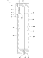
- FIG. 11 is a diagram showing a tenth example of the separation device 1 in the embodiment.
- the separation device 1 includes a hydrophilic portion 10, a separation filter 20, and a base material 30.
- the base material 30 has an injection port 31 formed in a cylindrical shape and formed at one end, and a collection port 32 formed on the opposite side of the injection port 31.
- the base material 30 for example, glass, plastic, metal or the like is used.
- the separation filter 20 is arranged inside the base material 30 away from the collection port 32.
- the first main surface 21 is arranged on the injection port 31 side, and the second main surface 22 is arranged on the collection port 32 side.
- the end face 23 is provided in a part of the hydrophilic portion 10.
- the hydrophilic portion 10 is provided on the inner surface 30a from the injection port 31 to the collection port 32.
- FIG. 12 is a diagram for explaining a method of separating serum or plasma from a liquid sample using the tenth example of the separation device 1 in the embodiment.
- the user collects blood from the subject, uses the collected blood as a liquid sample, and injects blood from the injection port 31. Then, a predetermined amount of the injected blood is dropped onto the first main surface 21 of the separation filter 20. The dropped blood flows in the separation filter 20 toward the second main surface 22 of the separation filter 20 based on the capillary phenomenon in the direction of the arrow M shown in FIG. Plasma or serum is separated from blood by flowing through the separation filter 20.
- the hydrophilic part 10 is made of a hydrophilic material.
- the serum or plasma that has reached the hydrophilic portion 10 will flow from the second main surface 22 of the separation filter 20 onto the hydrophilic portion 10 without being absorbed by the hydrophilic portion 10. Therefore, it is possible to take out serum or plasma in a liquid state.
- the serum or plasma taken out in a liquid state is collected in the storage container 8 prepared in advance on the lower side of the collection port 32.
- the base material 30 formed in a tubular shape is further provided, and the base material 30 is formed on one side of the injection port 31 and on the opposite side of the injection port 31.
- the collection port 32 and the hydrophilic portion 10 are provided on the inner surface of the base material 30, and the separation filter 20 is arranged inside the base material 30 away from the recovery port 32.
- the serum or plasma flows from the second main surface 22 of the separation filter 20 onto the hydrophilic portion 10 without being absorbed by the hydrophilic portion 10. Therefore, the user can take out serum or plasma in a liquid state.
- the base material 30 is formed in a tubular shape, it is possible to prevent the separated serum or plasma from leaking to the outside of the base material 30. Therefore, serum or plasma can be efficiently collected.
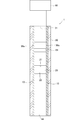
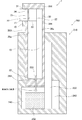
- FIG. 13 is a diagram showing an eleventh example of the separation device 1 in the embodiment.
- the separation device 1 includes a hydrophilic portion 10, a separation filter 20, a base material 30, and a hydrophobic portion 40.
- the hydrophilic portion 10 is provided on the inner surface 30a on the side of the collection port 32 from the injection port 31.
- the base material 30 is provided with a hydrophobic portion 40 by coating or the like at the end of the inner surface 30a on the recovery port 32 side.
- the inner diameter of the base material 30 is sufficiently small, and is composed of a diameter such that the separated serum or plasma develops a capillary phenomenon inside the base material 30, and is preferably 7 mm or less, for example.
- the base material 30 is formed from the injection port 31 to the recovery port 32 with substantially the same inner diameter.
- the base material 30 may have an inner surface 30a formed in a tapered shape so that the inner diameter of the injection port 31 is larger than the inner diameter of the recovery port 32.
- the hydrophobic part 40 is made of a hydrophobic material.
- the hydrophobic material include polyethylene, polypropylene, polyimide, SU-8, resist, fluororesin, and hydrophobic glass.
- a surface hydrophilic treatment method a method in which a hydrophobic function is added to the surface of a hydrophobic portion by forming a surface uneven structure by plasma treatment or laser or etching treatment is used.
- FIG. 14 is a diagram for explaining a method of separating serum or plasma from a liquid sample using the eleventh example of the separation device 1 in the embodiment.
- the user collects blood from the subject, uses the collected blood as a liquid sample, and injects blood from the injection port 31. Then, a predetermined amount of the injected blood is dropped onto the first main surface 21 of the separation filter 20.
- the dropped blood flows in the separation filter 20 in the direction of the arrow M shown in FIG. 14 toward the second main surface 22 of the separation filter 20 based on the capillary phenomenon. Plasma or serum is separated from blood by flowing through the separation filter 20.
- the hydrophilic part 10 is made of a hydrophilic material.
- the serum or plasma that has reached the hydrophilic portion 10 will flow from the second main surface 22 onto the hydrophilic portion 10 without being absorbed by the hydrophilic portion 10. Therefore, it is possible to take out serum or plasma in a liquid state.
- a hydrophobic portion 40 made of a hydrophobic material is provided at the end of the inner surface 30a on the recovery port 32 side of the base material 30.
- the contact angle between the serum or plasma and the hydrophobic portion 40 is increased. Therefore, the serum or plasma is collected in the space V between the separation filter 20 and the hydrophobic portion 40 inside the base material 30. That is, the serum or plasma does not flow out from the collection port 32 side to the outside of the base material 30.
- a hydrophobic portion 40 made of a hydrophobic material is further provided at the end of the inner surface 30a of the base material 30 on the recovery port 32 side.
- FIG. 15 is a diagram showing a twelfth example of the separation device 1 in the embodiment.
- the separation device 1 includes a hydrophilic portion 10, a separation filter 20, a base material 30, and a suction portion 50.
- the suction unit 50 is provided on the recovery port 32 side and is for sucking the air inside the base material 30 from the recovery port 32 side.
- the suction unit 50 is removable from the collection port 32.
- a piston or the like that can move from the separation filter 20 toward the collection port 32 side along the hydrophilic portion 10 of the inner surface 30a of the base material 30 is used.
- FIG. 16 is a diagram for explaining a method of separating serum or plasma from a liquid sample using the twelfth example of the separation device 1 in the embodiment.
- the user collects blood from the subject, uses the collected blood as a liquid sample, puts the blood in the container 59, and brings the injection port 31 into contact with the blood in the container 59. Then, the suction portion 50 arranged in the vicinity of the separation filter 20 is slid toward the recovery port 32 side in the direction of arrow N in the drawing along the hydrophilic portion 10 of the inner surface 30a of the base material 30. As a result, blood is injected into the base material 30 from the injection port 31. Then, the injected blood reaches the first main surface 21 of the separation filter 20. The arriving blood flows in the separation filter 20 in the direction of the arrow M shown in FIG. 16 toward the second main surface 22 of the separation filter 20 based on the capillary phenomenon. Plasma or serum is separated from blood by flowing through the separation filter 20.
- the hydrophilic part 10 is made of a hydrophilic material.
- the serum or plasma that has reached the hydrophilic portion 10 will flow from the second main surface 22 onto the hydrophilic portion 10 without being absorbed by the hydrophilic portion 10. Therefore, it is possible to take out serum or plasma in a liquid state.
- a suction unit 50 for sucking the air inside the base material 30 from the recovery port 32 side is further provided.
- the capillary phenomenon of blood flowing through the separation filter 20 is promoted, and serum or plasma can be separated from blood more quickly. Therefore, serum or plasma can be taken out more efficiently.
- FIG. 17 is a diagram showing a thirteenth example of the separation device 1 in the embodiment.
- the separation device 1 includes a hydrophilic portion 10, a separation filter 20, a base material 30, and an air supply portion 60.
- the air supply unit 60 is provided on the injection port 31 side, and is for sending the air inside the base material 30 from the injection port 31 side.
- the air supply unit 60 is removable from the injection port 31.
- a piston or the like that can move from the injection port 31 side toward the separation filter 20 along the hydrophilic portion 10 of the inner surface 30a of the base material 30 is used.
- a transmission filter 61 is provided in the space inside the base material 30 between the injection port 31 and the separation filter 20.
- the permeation filter 61 is capable of permeating a liquid sample and a gas such as air.
- a film mainly composed of polypropylene, a film mainly composed of polyethylene, and a film mainly composed of polyolefin. Porous film, PTFE membrane film, Ultra-high molecular weight polyethylene porous film manufactured by Nitto Denko Co., Ltd., Sunmap (registered trademark) manufactured by Nitto Denko Co., Ltd., Breathlon (registered trademark) manufactured by Nitto Denko Co., Ltd. , Nitto Denko Co., Ltd.
- breathable adhesive tape Nitothru registered trademark
- Mitsubishi Chemical Co., Ltd. breathable film KTF Mitsubishi Chemical Co., Ltd.
- breathable breathable waterproof film Excelpol registered trademark
- 3M Japan Co., Ltd. "Microporous film” manufactured by Tokuyama Co., Ltd., microporous film “NF sheet” manufactured by Tokuyama Co., Ltd., Milime manufactured by Teijin Co., Ltd., etc. are used.
- FIG. 18 is a diagram for explaining a method of separating serum or plasma from a liquid sample using the thirteenth example of the separation device 1 in the embodiment
- FIG. 18 (a) is a diagram for explaining a method for separating serum or plasma from the liquid sample. Is a diagram showing a state in which serum or plasma is injected into the injection port 31
- FIG. 18B is a diagram showing a state in which serum or plasma is separated from a liquid sample.
- the user collects blood from the subject, uses the collected blood as a liquid sample, and injects blood from the injection port 31. Then, a predetermined amount of the injected blood is dropped onto the first main surface 21 of the separation filter 20. Then, the user arranges the air supply unit 60 on the injection port 31 side. The user slides the arranged air supply unit 60 toward the separation filter 20 side along the inner surface 30a of the base material 30. As a result, the blood flows in the separation filter 20 toward the second main surface 22 based on the capillary phenomenon in the direction of the arrow M shown in FIG. 18 (b). Plasma or serum is separated from blood by flowing through the separation filter 20.
- the hydrophilic part 10 is made of a hydrophilic material.
- the serum or plasma that has reached the hydrophilic portion 10 will flow from the second main surface 22 onto the hydrophilic portion 10 without being absorbed by the hydrophilic portion 10. Therefore, it is possible to take out serum or plasma in a liquid state.
- the serum or plasma taken out in a liquid state is collected in the storage container 8 prepared in advance on the lower side of the collection port 32.
- an air supply unit 60 for sending air from the injection port 31 side to the inside of the base material 30 is further provided.
- the capillary phenomenon of blood flowing through the separation filter 20 is promoted, and serum or plasma can be separated from blood more quickly. Therefore, serum or plasma can be taken out more efficiently.
- the transmission filter 61 is provided in the space inside the base material 30 between the injection port 31 and the separation filter 20.
- unnecessary substances such as dust and dirt in the air sent to the inside of the base material 30 can be removed by the air supply unit 60, and the air sent to the separation filter 20 can be purified. Therefore, it is possible to prevent unnecessary substances from being mixed with blood, and it is possible to take out serum or plasma more efficiently.
- FIG. 19 is a diagram showing a first example of the detection device 100 in the embodiment.
- the detection device 100 is for detecting a biological substance.
- the detection device 100 includes a separation device 1 and a detection unit 110.
- the separation device 1 includes a hydrophilic portion 10 and a separation filter 20.
- the hydrophilic portion 10 is formed in a plate shape.
- the hydrophilic portion 10 is made of a hydrophilic material.
- the hydrophilic portion 10 is made of a hydrophilic film.
- the hydrophilic portion 10 connects the first main surface 11 on which the separation filter 20 is provided, the second main surface 12 on the side opposite to the first main surface 11, and the first main surface 11 and the second main surface 12. It has an end face 13.
- the separation filter 20 is made of either a hollow fiber or a porous material.
- the separation filter 20 is provided in a part of the hydrophilic portion 10.
- the separation filter 20 has an absorbent material 25 on the first main surface 21.
- the second main surface 22 is installed in a part of the hydrophilic portion 10.
- the detection unit 110 detects the biological substance from the serum or plasma separated from the separation device 1.
- the biological material is, for example, glucose.
- the biological material may be an antigen or an antibody.
- the biological material may be DNA.
- the biological material may be RNA.
- the biological substance may be an inorganic substance such as sulfurous acid or sulfite.
- the biological material may be an exosome.
- the biological material may be an organic substance.
- the detection unit 110 includes a permeation layer 120, an antireflection layer 130, a reaction layer 140, and a transparent layer 150.
- the permeation layer 120 is for permeating the separated serum or plasma.
- the permeation layer 120 is composed of chemical fibers such as polyester, cotton, nanocellulose, nitrocellulose, fine metal wires, plastic filters, hydrophobic substances, hydrophilic substances, and porous substances such as zeolite.
- the permeation layer 120 is provided in the hydrophilic portion 10 apart from the separation filter 20.
- the permeation layer 120 is provided on the first main surface 11 of the hydrophilic portion 10.
- the antireflection layer 130 detects the color of only the reaction layer 140, the colors of the transparent layer 150 and the permeation layer 120 provided on both sides of the antireflection layer 130 are mixed with the color of the reaction layer 140. This is to prevent erroneous color from being detected at the time of detection.
- the antireflection layer 130 is composed of a porous substance such as titanium oxide, gold nanoparticles, inorganic particles, and zeolite.
- the antireflection layer 130 is provided on the opposite side of the hydrophilic portion 10 with the permeation layer 120 interposed therebetween.
- the antireflection layer 130 is laminated on the upper side of the permeation layer 120.
- the antireflection layer 130 may be omitted.
- the reaction layer 140 is for causing a color reaction with the separated serum or plasma.
- the reaction layer 140 is provided on the side opposite to the hydrophilic portion 10 with the permeation layer 120 interposed therebetween.
- the reaction layer 140 is arranged on the first main surface 11 side of the hydrophilic portion 10.
- the reaction layer 140 is laminated on the upper side of the antireflection layer 130.
- the reaction layer 140 is provided on the opposite side of the permeation layer 120 with the antireflection layer 130 interposed therebetween.
- the reaction layer 140 is composed of, for example, chemical fibers such as nitrocellulose and polyester, cotton, nanocellulose, fine metal wires, and a plastic filter.
- the reaction layer 140 is a porous substance such as an antibody, an enzyme, a buffer solution, a reagent, DNA, RNA, a fluorescent substance, Rnace, Dnace, a virus, a micrometal, a catalyst, and a zeolite in order to cause a color reaction with the separated serum or plasma.
- a porous substance such as an antibody, an enzyme, a buffer solution, a reagent, DNA, RNA, a fluorescent substance, Rnace, Dnace, a virus, a micrometal, a catalyst, and a zeolite in order to cause a color reaction with the separated serum or plasma.
- Collagen, peptide, sucrose, trehalose, maltose and the like Collagen, peptide, sucrose, trehalose, maltose and the like.
- the biological substance to be detected is glucose
- a color reaction by an enzymatic method may occur in the reaction layer 140.
- the reaction layer 140 contains an enzyme such as glucose oxidase and peroxidase.
- the serum or plasma separated by the separation device 1 reacts with glucose oxidase contained in the reaction layer 140 to generate hydrogen peroxide.
- the generated hydrogen peroxide reacts with peroxidase contained in the reaction layer 140, and the reaction layer 140 develops a bluish purple color.
- a color reaction may occur in the reaction layer 140 by a competitive method such as an antibody method or a sandwich method.
- the reaction layer 140 contains a second antigen or antibody that binds to the first antigen or antibody contained in the biological substance.
- the first antigen or antibody contained in the serum or plasma separated by the separator 1 binds to the second antigen or antibody contained in the reaction layer 140.
- the secondary antibody solution containing the labeled antigen or antibody is added dropwise, and then the labeling agent contained in the secondary antibody solution is made to emit light.
- the luminescent solution is dropped, the reaction layer develops color.
- a color-developing reaction by a polymerase chain reaction may occur in the reaction layer 140.
- the reaction layer 140 contains a reagent.
- This reagent includes, for example, a thermostable enzyme for PCR, a reaction buffer, a reaction substrate (dNTPs), a PCR primer (oligonucleotide), a fluorescent intercalator and the like.
- dNTPs reaction substrate
- PCR primer oligonucleotide
- fluorescent intercalator a fluorescent intercalator and the like.
- a polymerase chain reaction occurs in the reaction layer 140 by heating the reaction layer 140 by a predetermined means such as a Perche element, and the reaction layer 140 Fluorescently develops.
- the amount of DNA can also be measured by measuring the amount of color development.
- RNA when the biological substance to be detected is RNA, a color-developing reaction by a polymerase chain reaction (PCR method) may occur in the reaction layer 140.
- the reaction layer 140 contains amplification reagents such as reverse transcriptase and primers.
- amplification reagents such as reverse transcriptase and primers.
- the RNA is converted to cDNA by the reverse transcriptase contained in the reaction layer 140.
- a predetermined means such as a Perche element
- the gene is amplified by the amplification reagent
- a polymerase chain reaction occurs in the reaction layer 140, and the reaction layer 140 is fluorescently colored.
- the amount of RNA can also be measured by measuring the amount of color development.
- the biological substance to be detected is DNA
- a color reaction by DETECTR, SHERLOCK method, or SHERLOCK v2 may occur in the reaction layer 140.
- the reaction layer 140 contains a reagent containing a CaS enzyme, a buffer, and the like.
- a polymerase chain reaction occurs in the reaction layer 140 by heating the reaction layer 140 by a predetermined means such as a Perche element.
- the CRISPR enzyme acts and base cleavage occurs.
- base cleavage a substance having a specific base sequence having luminescent substances at both ends is also cleaved, so that the reaction layer 140 emits light.
- the amount of DNA can also be measured by measuring the amount of luminescence.
- RNA when the biological substance to be detected is RNA, a color reaction by the SHERLOCK method or SHERLOCK v2 may occur in the reaction layer 140.
- the reaction layer 140 contains a reverse transcription enzyme, an amplification reagent such as a primer, a CRISPR enzyme, and a guide RNA.
- an amplification reagent such as a primer, a CRISPR enzyme, and a guide RNA.
- the separated serum or plasma contains a sequence of a specific RNA to be detected, it is converted from RNA to cDNA by the reverse transcriptase contained in the reaction layer 140.
- a predetermined means such as a Perche element
- the gene is amplified by the amplification reagent, and the polymerase chain reaction occurs in the reaction layer 140.
- the CRISPR enzyme acts and base cleavage occurs.
- base cleavage a substance having a specific base sequence having luminescent substances at both ends is also cleaved, so that the reaction layer 140 emits light.
- the amount of DNA can also be measured by measuring the amount of luminescence.
- the reaction layer 140 may cause a color-developing reaction due to an iodine-starch reaction.
- the reaction layer 140 contains potassium iodate (KIO 3 ) and starch.
- KIO 3 potassium iodate
- the reaction layer 140 develops a bluish purple color due to potassium iodate and starch in the reaction layer 140.
- the transparent layer 150 is made of a transparent film, and for example, PET (Polyethylene terephthalate) is used.
- PET Polyethylene terephthalate
- a film material such as polycarbonate, glass, SU-8, a transparent resist, a polyvinylidene chloride film, or a porous material such as a polyimide film or zeolite may be used.
- the transparent layer 150 is provided on the opposite side of the permeation layer 120 with the reaction layer 140 interposed therebetween.
- the transparent layer 150 is laminated on the upper side of the reaction layer 140.
- the transparent layer 150 may be omitted.
- the user collects blood from the subject, and drops the collected blood as a liquid sample onto the absorbent material 25 in a predetermined amount.
- the dropped blood is absorbed by the absorbent material 25.
- the blood that cannot be completely absorbed by the absorbent material 25 flows through the separation filter 20 toward the second main surface 22 and the end surface 23 of the separation filter 20 based on the capillary phenomenon. Plasma or serum is separated from blood by flowing through the separation filter 20.
- the hydrophilic part 10 is made of a hydrophilic material. As a result, the serum or plasma that has reached the hydrophilic portion 10 will flow from the end face 23 onto the hydrophilic portion 10 without being absorbed by the hydrophilic portion 10.
- Serum or plasma flowing on the hydrophilic portion 10 reaches the osmotic layer 120 provided on the hydrophilic portion 10 and permeates into the osmotic layer 120.
- serum or plasma can uniformly permeate the inside of the permeation layer 120.
- the serum or plasma that has permeated the permeation layer 120 further permeates into the antireflection layer 130. Serum or plasma that has penetrated the antireflection layer 130 reaches the reaction layer 140. The serum or plasma that has reached the reaction layer 140 undergoes a color reaction with the reaction layer 140. As a result, the detection unit 110 can detect a biological substance showing a color-developing reaction from serum or plasma. The user can visually or visually confirm the reaction layer 140 that has undergone a color reaction with serum or plasma.
- the detection device 100 for detecting a biological substance the separation device 1 for separating serum or plasma from a liquid sample containing a sample collected from a living body or soil, and the like.
- a detection unit 110 for detecting a biological substance from serum or plasma separated from the separation device 1 is provided, and the separation device 1 is provided in a hydrophilic part 10 made of a hydrophilic material and a part of the hydrophilic part 10.
- a separation filter 20 made of a hollow thread or a porous material is provided, and the detection unit 110 is provided with a permeation layer 120 provided in the hydrophilic part 10 for permeating the separated serum or plasma, and permeates. It has a reaction layer 140 for causing a color reaction with the separated serum or plasma, which is provided on the opposite side of the layer 120 from the hydrophilic portion 10.
- the reaction layer 140 is arranged on the first main surface 11 side of the hydrophilic portion 10. That is, both the separation filter 20 and the reaction layer 140 are arranged on the first main surface 11 side of the hydrophilic portion 10.
- the surface on which the liquid sample is dropped and the color-developing surface of the reaction layer 140 are oriented in the same direction. Therefore, the direction in which the user visually observes the reaction layer 140 and the direction of the optical device for confirming the reaction layer 140 can be the same as the direction in which the liquid sample is dropped. As a result, it is possible to facilitate visual inspection of the reaction layer 140 and confirmation with an optical device.
- the detection unit 110 has a transparent layer 150 made of a transparent film provided on the opposite side of the permeation layer 120 with the reaction layer 140 interposed therebetween.
- a transparent layer 150 made of a transparent film provided on the opposite side of the permeation layer 120 with the reaction layer 140 interposed therebetween.
- the present embodiment has an antireflection layer 130. As a result, it is possible to prevent the color of the reaction layer 140 from being mixed or mixed with the color of the reaction layer 140, and it is possible to suppress the detection of an erroneous color at the time of detection.
- the present embodiment has an absorbent material 25 for absorbing a liquid sample.
- the absorbent material 25 for absorbing a liquid sample.
- FIG. 20 is a diagram showing a second example of the detection device 100 in the embodiment.
- the detection device 100 includes a separation device 1 and a detection unit 110.
- the separation device 1 includes a hydrophilic portion 10 and a separation filter 20.
- the detection unit 110 includes a permeation layer 120, an antireflection layer 130, a reaction layer 140, and a transparent layer 150.
- the permeation layer 120 is provided in the hydrophilic portion 10 apart from the separation filter 20.
- the permeation layer 120 is provided on the end face 13 of the hydrophilic portion 10.
- the antireflection layer 130 is provided on the second main surface 12 side of the hydrophilic portion 10.
- the antireflection layer 130 is laminated under the permeation layer 120.
- the antireflection layer 130 may be omitted.
- the reaction layer 140 is arranged on the second main surface 12 side of the hydrophilic portion 10.
- the reaction layer 140 is laminated under the antireflection layer 130.
- the reaction layer 140 is provided on the opposite side of the permeation layer 120 with the antireflection layer 130 interposed therebetween.
- the transparent layer 150 is provided on the opposite side of the permeation layer 120 with the reaction layer 140 interposed therebetween.
- the transparent layer 150 is laminated under the reaction layer 140.
- the transparent layer 150 is provided on the opposite side of the antireflection layer 130 with the reaction layer 140 interposed therebetween.
- the transparent layer 150 may be omitted.
- the user collects blood from the subject, and drops the collected blood as a liquid sample onto the absorbent material 25 in a predetermined amount.
- the dropped blood is absorbed by the absorbent material 25.
- the blood that cannot be completely absorbed by the absorbent material 25 flows through the separation filter 20 toward the second main surface 22 and the end surface 23 of the separation filter 20 based on the capillary phenomenon. Plasma or serum is separated from blood by flowing through the separation filter 20.
- the hydrophilic part 10 is made of a hydrophilic material. As a result, the serum or plasma that has reached the hydrophilic portion 10 will flow from the end face 23 onto the hydrophilic portion 10 without being absorbed by the hydrophilic portion 10.
- Serum or plasma flowing on the hydrophilic portion 10 reaches the permeation layer 120 provided on the end face 13 of the hydrophilic portion 10 and permeates into the permeation layer 120.
- the serum or plasma that has permeated the permeation layer 120 further permeates into the antireflection layer 130. Serum or plasma that has penetrated the antireflection layer 130 reaches the reaction layer 140. The serum or plasma that has reached the reaction layer 140 undergoes a color reaction with the reaction layer 140. As a result, the detection unit 110 can detect a biological substance showing a color-developing reaction from serum or plasma. The user can visually or visually confirm the reaction layer 140 that has undergone a color reaction with serum or plasma.
- the reaction layer 140 is arranged on the second main surface 12 side of the hydrophilic portion 10. That is, the separation filter 20 is arranged on the first main surface 11 side of the hydrophilic portion 10, and the reaction layer 140 is arranged on the second main surface 12 side of the hydrophilic portion 10.
- the surface on which the liquid sample is dropped and the color-developing surface of the reaction layer 140 are in opposite directions. Therefore, the direction in which the user visually observes the reaction layer 140 and the direction of the optical device for confirming the reaction layer 140 can be opposite to the direction in which the liquid sample is dropped. As a result, the optical device and the like can be miniaturized.
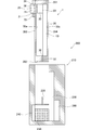
- FIG. 21 is a diagram showing a first example of the storage device 200 in the embodiment.
- the storage device 200 is for storing serum or plasma.
- the storage device 200 includes a separation device 1 and a container 210.
- the separation device 1 includes a hydrophilic portion 10, a separation filter 20, a base material 30, and a lid portion 70.
- the outer shape of the base material 30 is formed in a rectangular parallelepiped shape, and a rectangular parallelepiped space is formed inside.
- the base material 30 is made of, for example, plastic, metal, or the like.
- the base material 30 has an upper wall 391, a lower wall 392, a first side wall 393, a second side wall 394, a third side wall, and a fourth side wall (the third side wall and the fourth side wall are not shown). Omitted).
- the upper wall 391 and the lower wall 392 are arranged facing each other.
- the first side wall 393, the second side wall 394, the third side wall and the fourth side wall connect the upper wall 391 and the lower wall 392.
- the first side wall 393 and the second side wall 394 are arranged so as to face each other.
- the third side wall and the fourth side wall are arranged so as to face each other.
- the base material 30 has an opening port 31 and a collection port 32 opened apart from the injection port 31.
- the injection port 31 is provided on the first side wall 393.
- the collection port 32 is provided on the lower wall 392.
- the base material 30 is provided by fitting the absorbent material 25 into the injection port 31.
- the base material 30 is provided with a valve portion 36 made of rubber or the like at the collection port 32.
- the base material 30 is separated from the absorbent material 25, and a separation filter 20 is provided inside.
- the base material 30 is provided with a hydrophilic portion 10 on the inner surface 30a of the second side wall 394.
- the base material 30 may be provided with hydrophilic portions 10 on all of the inner surfaces 30a.
- the base material 30 has a claw portion 34 protruding inside.
- the claw portion 34 is arranged between the absorbent material 25 provided at the injection port 31 and the separation filter 20.
- the claw portion 34 is formed smaller than the absorbent material 25. Further, the claw portion 34 is formed smaller than the separation filter 20.
- the lid portion 70 is for covering the injection port 31.
- the lid 70 is removable from the injection port 31.
- the lid portion 70 may be provided so that the first side wall 393 can be slidable.
- the lid 70 has an extrusion mechanism 71 for extruding the absorbent material 25 provided at the injection port 31 into the base material 30.
- the hydrophilic portion 10 is formed in a plate shape.
- the hydrophilic portion 10 is made of a hydrophilic material.
- the hydrophilic portion 10 is made of a hydrophilic film.
- the separation filter 20 is made of either a hollow fiber or a porous material.
- the separation filter 20 is provided in a part of the hydrophilic portion 10.
- the separation filter 20 is provided with an absorbent material 25 separated from the first main surface 21.
- an absorbent material 25 a sponge or the like in which a synthetic resin such as polyurethane is foam-molded is used.
- the second main surface 22 is installed in a part of the hydrophilic portion 10.
- the accommodator 210 can accommodate the separating device 1.
- the container 210 includes an insertion unit 220, a storage liquid 230, a temperature sensor 240, a temperature control unit 250, and a battery 260.
- the insertion portion 220 can be inserted into the collection port 32 of the base material 30.
- the insertion portion 220 is formed in a needle shape, for example.
- the storage solution 230 is for storing the separated serum or plasma.
- the storage liquid 230 for example, EDTA or the like is used.
- the temperature sensor 240 detects the temperature inside the container 210.
- a known temperature sensor may be used as the temperature sensor 240.
- the temperature control unit 250 controls the temperature inside the container 210.
- the temperature control unit 250 is controlled to reach a predetermined temperature according to the temperature inside the container 210 detected by the temperature sensor 240.
- the temperature control unit 250 is composed of a Perche element and an electronic circuit. The temperature control unit 250 can heat and cool by applying an electric potential to the Pelche element.
- the battery 260 supplies electric power to the temperature sensor 240 and the temperature control unit 250.
- FIG. 22 is a diagram for explaining a method of separating serum or plasma from a liquid sample by using the separation device 1 of the first example of the storage device 200 in the embodiment.
- FIG. 23 is a diagram for explaining a storage method for storing serum or plasma using the first example of the storage device 200 in the embodiment.
- the separation device 1 is installed so that the second side wall 394 is on the lower side.
- the user collects blood from the subject, and drops the collected blood as a liquid sample onto the absorbent material 25 in a predetermined amount.
- the absorbent material 25 and the separation filter 20 are separated from each other by the claw portion 34.
- the lid 70 is installed in the injection port 31, and the absorbent material 25 is pushed out toward the inside of the base material 30 by the extrusion mechanism 71.
- the absorbent material 25 that has absorbed blood is pushed out into the base material 30, and the blood absorbed by the absorbent material 25 reaches the separation filter 20.
- the hydrophilic portion 10 is made of a hydrophilic material. As a result, the serum or plasma that has reached the hydrophilic portion 10 will flow from the end face 23 onto the hydrophilic portion 10 without being absorbed by the hydrophilic portion 10. The serum or plasma flowing on the hydrophilic portion 10 will be collected inside the base material 30.
- the separation device 1 is housed in the container 210.
- the collection port 32 of the base material is inserted into the insertion portion 220 of the accommodator 210.
- the insertion portion 220 breaks through the valve portion 36 provided in the collection port 32, the serum or plasma collected inside the base material 30 is mixed with the preservation solution 230, and the preservation solution 230 inside the container 210 is mixed. It will be saved in.
- the inside of the container 210 is controlled to a predetermined temperature by the temperature control unit 250 according to the temperature detected by the temperature sensor 240.
- the storage device 200 for storing serum or plasma is separated from the separation device 1 for separating serum or plasma from a liquid sample containing a sample collected from a living body.
- a container 210 capable of accommodating the device 1 is provided, and the separation device 1 is provided in a hydrophilic portion 10 made of a hydrophilic material and a part of the hydrophilic portion 10, and is made of a hollow thread or a porous material. It has a separation filter 20 and a container 210, which contains a storage solution 230 for storing the separated serum or plasma.
- the user can store the serum or plasma separated from the liquid sample as it is in the storage solution 230. In this way, it is not necessary to bother to collect the separated serum or plasma and transfer the collected serum or plasma to a storage container. Therefore, serum or plasma can be easily stored.
- the serum or plasma stored in the storage device 200 is small, it can be sent by mail or the like. For this reason, even if the collection institution that collects the liquid sample and the analysis institution that analyzes serum or plasma are geographically distant, they should be sent hygienically without the need for a large storage container. Can be done.
- the collection port 32 is provided with a valve portion 36, and the container 210 has an insertion portion 220 that can be inserted into the collection port 32 of the base material 30.
- the serum or plasma collected inside the base material 30 for the first time after inserting the insertion portion 220 into the collection port 32 is stored in the storage solution 230.
- the separated serum or plasma can be stored in the preservation solution 230 as it is in the preservation solution 230 without being exposed to the outside air. Therefore, it is possible to prevent deterioration of serum or plasma.
- the separation device 1 has a lid portion 70 for covering the injection port 31, and the lid portion 70 is an absorbent material for absorbing a liquid sample provided in the injection port 31.
- the base material 30 has an extrusion mechanism 71 for extruding the 25 into the inside of the base material 30, and the base material 30 has a claw portion 34 between the absorbent material 25 and the separation filter 20.
- the present embodiment has an absorbent material 25 for absorbing a liquid sample.
- the absorbent material 25 for absorbing a liquid sample.
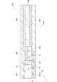
- FIG. 24 is a diagram showing a second example of the storage device 200 in the embodiment.
- the storage device 200 is for storing serum or plasma.
- the storage device 200 includes a separation device 1 and a container 210.
- the separation device 1 includes a hydrophilic portion 10, a separation filter 20, a base material 30, and a lid portion 70.
- the base material 30 has an injection port 31 on the upper wall 391.
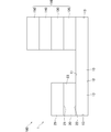
- FIG. 25 is a diagram showing a first example of the sensor 300 in the embodiment.
- the sensor 300 is for storing serum or plasma.
- the sensor 300 includes a separation device 1 and a measurement unit 310.
- the separation device 1 includes a hydrophilic portion 10, a separation filter 20, a pair of base materials 30, and a spacer 80.
- the base material 30 is formed in a plate shape.
- the base material 30 is made of, for example, plastic, metal, or the like.
- the base material 30 is formed in a rectangular parallelepiped shape.
- first base material 30-1 Of the pair of base materials 30, one is designated as the first base material 30-1 and the other is designated as the second base material 30-2.
- An injection port 31 for injecting a sample is formed between the end of the first base material 30-1 and the end of the second base material 30-2.
- a spacer 80 is provided between the first base material 30-1 and the second base material 30-2 at a distance from the injection port 31. By providing the spacer 80, a space is formed between the first base material 30-1 and the second base material 30-2.
- a first space P is formed between the first base material 30-1 and the second base material 30-2 on the injection port 31 side, and a first space P is formed on the opposite side of the first space P with the separation filter 20 interposed therebetween. Two spaces Q are formed.
- the cross-sectional area of the first space P is larger than the cross-sectional area of the second space Q.
- the first base material 30-1 is provided with hydrophilic portions 10 on the first space P side and the second space Q side with the separation filter 20 interposed therebetween.
- the second base material 30-2 is provided with a hydrophilic portion 10 on the first space P side with the separation filter 20 interposed therebetween.
- the hydrophilic portion 10 of the first base material 30-1 and the hydrophilic portion 10 of the second base material 30-2 are arranged so as to face each other and are arranged apart from each other.
- the distance between the hydrophilic portion 10 of the first base material 30-1 and the hydrophilic portion 10 of the second base material 30-2 is sufficiently narrow, and is composed of a distance such that the capillary phenomenon of the liquid sample is developed.
- the separation filter 20 is provided in a part of the hydrophilic portion 10.
- the separation filter 20 is provided between the hydrophilic portion 10 of the first base material 30-1 and the hydrophilic portion 10 of the second base material 30-2.
- the measuring unit 310 measures biological substances from serum or plasma separated by the separating device 1.
- the measuring unit 310 includes a reaction unit 320, a conversion unit 330, a control electrode 340, and a temperature control unit 350.
- the reaction unit 320 is for chemically reacting with the separated serum or plasma.
- the reaction unit 320 is provided between the first base material 30-1 and the second base material 30-2.
- the reaction unit 320 is provided on the side opposite to the injection port 31 with the separation filter 20 interposed therebetween.
- the reaction unit 320 is composed of, for example, chemical fibers such as nitrocellulose and polyester, cotton, nanocellulose, fine metal wires, and a plastic filter.
- the reaction unit 320 includes antibodies, enzymes, buffers, reagents, DNA, RNA, fluorescent substances, Rnace, Dnace, viruses, micrometals, catalysts, porous substances such as zeolite, collagen, peptides, sucrose, trehalose, maltose, etc. Is included in 1 or more.
- one that causes a chemical reaction that occurs between the separated serum or plasma and the reaction layer 140 may be used.
- the conversion unit 330 converts the electrons generated based on the chemical reaction between the separated serum or plasma and the reaction unit 320 into a signal.
- the conversion unit 330 is composed of, for example, a working electrode, a reference electrode, and a counter electrode.
- the conversion unit 330 converts the electrons generated by the chemical reaction between the separated serum or plasma and the reaction unit 320 into an electric signal by, for example, a constant voltage method, a constant current method, cyclic voltammetry, or the like.
- the measuring unit 310 can quantitatively measure a biological substance by converting electrons into a signal by the converting unit 330.
- the conversion unit 330 may convert the light generated based on the chemical reaction between the separated serum or plasma and the reaction unit 320 into a signal.
- the conversion unit 330 is composed of a waveguide.
- the conversion unit 330 converts the light generated based on the chemical reaction between the separated serum or plasma and the reaction unit 320 into an electric signal by, for example, a constant voltage method, a constant current method, cyclic voltammetry, or the like.
- the measuring unit 310 can quantitatively measure a biological substance by converting light into a signal by the converting unit 330.
- the conversion unit 330 is provided between the first base material 30-1 and the second base material 30-2.
- the conversion unit 330 is fixed between the first base material 30-1 and the spacer 80.
- the conversion unit 330 may be fixed between the second base material 30-2 and the spacer 80.
- the conversion unit 330 is provided on the side opposite to the injection port 31 with the separation filter 20 interposed therebetween.
- the control electrode 340 applies current and voltage to the temperature control unit 350.
- the control electrode 340 is composed of one or more electrodes.
- the control electrode 340 is provided between the first base material 30-1 and the second base material 30-2.
- the control electrode 340 is fixed between the second base material 30-2 and the spacer 80.
- the control electrode 340 may be fixed between the first base material 30-1 and the spacer 80.
- the control electrode 340 is provided on the side opposite to the injection port 31 with the separation filter 20 interposed therebetween.
- the Lorentz force can cause Brownian motion in the fine particles contained in the reaction unit 320 to promote the reaction between serum or plasma and the reaction unit 320. ..
- the temperature control unit 350 controls the temperature of the space between the first base material 30-1 and the second base material 30-2.
- the temperature control unit 350 controls the temperature of the space between the first base material 30-1 and the second base material 30-2 so as to reach a predetermined temperature by the control electrode 340.
- the temperature control unit 350 is composed of a Perche element and an electronic circuit.
- the temperature control unit 350 can heat and cool the space between the first base material 30-1 and the second base material 30-2 by applying an electric potential through the control electrodes.
- the temperature control unit 350 can, for example, generate Brownian motion in the fine particles contained in the reaction unit 320 by heating to promote the reaction between serum or plasma and the reaction unit 320.
- the temperature control unit 350 is provided between the first base material 30-1 and the second base material 30-2.
- the temperature control unit 350 is fixed to the second base material 30-2.
- the temperature control unit 350 may be fixed to the first base material 30-1.
- the temperature control unit 350 is provided on the side opposite to the injection port 31 with the separation filter 20 interposed therebetween.
- the user collects blood from the subject, uses the collected blood as a liquid sample, and injects blood from the injection port 31.
- the blood injected from the injection port 31 reaches the separation filter 20 between the first base material 30-1 and the second base material 30-2 based on the capillary phenomenon.
- the blood flows in the separation filter 20 toward the second space Q side based on the capillary phenomenon. Plasma or serum is separated from blood by flowing through the separation filter 20.
- the hydrophilic part 10 is made of a hydrophilic material.
- the serum or plasma that has reached the hydrophilic portion 10 will flow from the separation filter 20 onto the hydrophilic portion 10 without being absorbed by the hydrophilic portion 10. Therefore, it is possible to take out serum or plasma in a liquid state.
- the serum or plasma separated by the separation filter 20 reaches the reaction unit 320.
- the serum or plasma that has reached the reaction unit 320 will chemically react with the reaction unit 320.
- the measurement unit 310 can measure the biological substance showing the chemical reaction from serum or plasma.
- the present embodiment is a sensor for measuring a biological substance, and is provided by a separation device 1 for separating serum or plasma from a liquid sample containing a sample collected from the living body, and a separation device 1.
- a measuring unit 310 for measuring a biological substance from separated serum or plasma is provided, and the separation device 1 is provided in a hydrophilic portion 10 made of a hydrophilic material and a part of the hydrophilic portion 10, and is hollow. It has a separation filter 20 made of a thread or a porous material, and the measuring unit 310 has a reaction unit 320 for chemically reacting with the separated serum or plasma, and a chemical reaction between the serum or plasma and the reagent. It has a conversion unit 330 that converts electrons generated based on the above into a signal.
- the present embodiment is a sensor for measuring a biological substance, and is provided by a separation device 1 for separating serum or plasma from a liquid sample containing a sample collected from the living body, and a separation device 1.
- a measuring unit 310 for measuring a biological substance from separated serum or plasma is provided, and the separation device 1 is provided in a hydrophilic portion 10 made of a hydrophilic material and a part of the hydrophilic portion 10, and is hollow. It has a separation filter 20 made of a thread or a porous material, and the measuring unit 310 has a reaction unit 320 for chemically reacting with the separated serum or plasma, and a chemical reaction between the serum or plasma and the reagent. It has a conversion unit 330 that converts the light generated based on the above into a signal.
- a spacer 80 is provided between the first base material 30-1 and the second base material 30-2 so as to be separated from the injection port 31. Thereby, the space between the first base material 30-1 and the second base material 30-2 can be maintained. Therefore, the liquid sample injected from the injection port 31 can reach the separation filter 20 based on the capillary phenomenon.
- FIG. 26 is a plan view showing a second example of the sensor 300 in the embodiment.
- the sensor 300 includes a separation device 1 and a measurement unit 310.
- the separation device 1 includes a hydrophilic portion 10, a separation filter 20, and a base material 30.
- the base material 30 is formed in a plate shape and has an injection port 31 for injecting a liquid sample and a groove-shaped flow path 37 connected from the injection port 31.
- the flow path 37 is provided with a hydrophilic portion 10.
- the flow path 37 branches from the branch portion 37a into a plurality of (two in the figure) flow paths 37. Further, the two flow paths 37 branched from the branch portion 37a further branch into two flow paths 37 from the branch portion 37b and the branch portion 37c, respectively.
- a measuring unit 310 is provided at the ends of the branch portion 37b and the four flow paths 37 branched from the branch portion 37c.
- a separation filter 20 is provided between the injection port 31 and the branch portion 37a.
- the user collects blood from the subject, uses the collected blood as a liquid sample, and injects blood from the injection port 31.
- the blood injected from the injection port 31 reaches the separation filter 20 via the flow path 37.
- the blood flows through the separation filter 20 toward the branch portion 37a based on the capillary phenomenon. Plasma or serum is separated from blood by flowing through the separation filter 20.
- the hydrophilic part 10 is made of a hydrophilic material.
- the serum or plasma that has reached the hydrophilic portion 10 will flow from the separation filter 20 onto the hydrophilic portion 10 without being absorbed by the hydrophilic portion 10. Therefore, it is possible to take out serum or plasma in a liquid state.
- each measuring unit 310 can measure a biological substance showing a chemical reaction from serum or plasma. In this way, a plurality of measurements of biological substances can be performed at the same time.
- Each measuring unit 310 may measure the same biological material or may measure different biological materials.
- FIG. 27 is a plan view showing a third example of the sensor 300 in the embodiment.
- FIG. 28 is a plan view showing a fourth example of the sensor 300 in the embodiment.
- the sensor 300 includes a separation device 1 and a measurement unit 310.
- the separation device 1 includes a hydrophilic portion 10, a separation filter 20, and a base material 30.
- the base material 30 is formed in the shape of a circular plate in a plan view.
- the base material 30 has an injection port 31 for injecting a liquid sample at substantially the center in a plan view, and four groove-shaped flow paths 37 extending radially from the injection port 31.
- the flow path 37 is provided with a hydrophilic portion 10.
- a measuring unit 310 is provided at the end of each flow path 37.
- the separation filter 20 is provided on the flow path 37 between the injection port 31 and the measuring unit 310. Further, as shown in FIG. 28, the separation filter 20 may be provided at the injection port 31 which is a branch point to each flow path 37.
- the user collects blood from the subject, uses the collected blood as a liquid sample, and injects blood from the injection port 31. As a result, the blood injected from the injection port 31 reaches the separation filter 20. Then, the blood flows through the flow path 37 in the separation filter 20 toward the measuring unit 310 based on the capillary phenomenon. Plasma or serum is separated from blood by flowing through the separation filter 20.
- the hydrophilic part 10 is made of a hydrophilic material.
- the serum or plasma that has reached the hydrophilic portion 10 will flow from the separation filter 20 onto the hydrophilic portion 10 without being absorbed by the hydrophilic portion 10. Therefore, it is possible to take out serum or plasma in a liquid state.
- the serum or plasma separated by the separation filter 20 reaches the measuring unit 310 provided at the end of the four flow paths 37.
- the measuring unit 310 can measure a biological substance that has shown a chemical reaction from serum or plasma.
Landscapes
- Health & Medical Sciences (AREA)
- Life Sciences & Earth Sciences (AREA)
- Immunology (AREA)
- Engineering & Computer Science (AREA)
- Chemical & Material Sciences (AREA)
- Hematology (AREA)
- Pathology (AREA)
- Biomedical Technology (AREA)
- General Physics & Mathematics (AREA)
- Biochemistry (AREA)
- Analytical Chemistry (AREA)
- Physics & Mathematics (AREA)
- Urology & Nephrology (AREA)
- General Health & Medical Sciences (AREA)
- Molecular Biology (AREA)
- Food Science & Technology (AREA)
- Medicinal Chemistry (AREA)
- Cell Biology (AREA)
- Microbiology (AREA)
- Biotechnology (AREA)
- Hydrology & Water Resources (AREA)
- Investigating Or Analysing Biological Materials (AREA)
Abstract
Un dispositif de séparation (1) est destiné à séparer le sérum et/ou le plasma d'un échantillon liquide contenant un objet collecté prélevé à partir d'un corps vivant ou d'un sol, et est caractérisé en ce qu'il comprend : une partie hydrophile (10) formée d'un matériau hydrophile ; et un filtre de séparation (20) qui est disposé dans une partie d'une région de la partie hydrophile (10) et qui est formé d'un matériau fibreux ou poreux creux.
Priority Applications (2)
| Application Number | Priority Date | Filing Date | Title |
|---|---|---|---|
| PCT/JP2020/007516 WO2021171378A1 (fr) | 2020-02-25 | 2020-02-25 | Dispositif de séparation, dispositif de détection, dispositif de conservation et capteur |
| JP2022502621A JP7399514B2 (ja) | 2020-02-25 | 2020-02-25 | 分離装置、検出装置、保存装置及びセンサ |
Applications Claiming Priority (1)
| Application Number | Priority Date | Filing Date | Title |
|---|---|---|---|
| PCT/JP2020/007516 WO2021171378A1 (fr) | 2020-02-25 | 2020-02-25 | Dispositif de séparation, dispositif de détection, dispositif de conservation et capteur |
Publications (1)
| Publication Number | Publication Date |
|---|---|
| WO2021171378A1 true WO2021171378A1 (fr) | 2021-09-02 |
Family
ID=77489985
Family Applications (1)
| Application Number | Title | Priority Date | Filing Date |
|---|---|---|---|
| PCT/JP2020/007516 WO2021171378A1 (fr) | 2020-02-25 | 2020-02-25 | Dispositif de séparation, dispositif de détection, dispositif de conservation et capteur |
Country Status (2)
| Country | Link |
|---|---|
| JP (1) | JP7399514B2 (fr) |
| WO (1) | WO2021171378A1 (fr) |
Citations (11)
| Publication number | Priority date | Publication date | Assignee | Title |
|---|---|---|---|---|
| JPH0534341A (ja) * | 1991-07-30 | 1993-02-09 | Terumo Corp | 血液成分分離保存装置 |
| US5916521A (en) * | 1995-01-04 | 1999-06-29 | Spectral Diagnostics, Inc. | Lateral flow filter devices for separation of body fluids from particulate materials |
| JP2000502451A (ja) * | 1995-12-22 | 2000-02-29 | ユニバーサル ヘルスウォッチ,インコーポレーテッド | 血漿分離をもたらす診断分析 |
| JP2000329761A (ja) * | 1989-04-07 | 2000-11-30 | Abbott Lab | 多孔質試薬放出システムおよびその製法 |
| JP2003135435A (ja) * | 2001-08-22 | 2003-05-13 | Kyowa Medex Co Ltd | 採血用具、これを用いた定量用溶液調製方法、定量用溶液調製器具及びその使用方法並びに定量用溶液を用いた定量方法 |
| JP2003194806A (ja) * | 2001-12-27 | 2003-07-09 | Minolta Co Ltd | 血球分離用チップ |
| JP2003254934A (ja) * | 2002-03-01 | 2003-09-10 | Matsushita Electric Ind Co Ltd | バイオセンサ |
| JP2011133235A (ja) * | 2009-12-22 | 2011-07-07 | Physical Screening Inc | 検査対象液保存器具 |
| JP2012529039A (ja) * | 2009-06-04 | 2012-11-15 | インフォピア カンパニー,リミテッド | 生体データ測定用のストリップ及び生体データ測定方法 |
| WO2014064921A1 (fr) * | 2012-10-22 | 2014-05-01 | パナソニック株式会社 | Dispositif à filtre |
| JP2019074344A (ja) * | 2017-10-12 | 2019-05-16 | Blue Industries株式会社 | 分離フィルタ、遺伝子解析用前処理キット |
-
2020
- 2020-02-25 JP JP2022502621A patent/JP7399514B2/ja active Active
- 2020-02-25 WO PCT/JP2020/007516 patent/WO2021171378A1/fr active Application Filing
Patent Citations (11)
| Publication number | Priority date | Publication date | Assignee | Title |
|---|---|---|---|---|
| JP2000329761A (ja) * | 1989-04-07 | 2000-11-30 | Abbott Lab | 多孔質試薬放出システムおよびその製法 |
| JPH0534341A (ja) * | 1991-07-30 | 1993-02-09 | Terumo Corp | 血液成分分離保存装置 |
| US5916521A (en) * | 1995-01-04 | 1999-06-29 | Spectral Diagnostics, Inc. | Lateral flow filter devices for separation of body fluids from particulate materials |
| JP2000502451A (ja) * | 1995-12-22 | 2000-02-29 | ユニバーサル ヘルスウォッチ,インコーポレーテッド | 血漿分離をもたらす診断分析 |
| JP2003135435A (ja) * | 2001-08-22 | 2003-05-13 | Kyowa Medex Co Ltd | 採血用具、これを用いた定量用溶液調製方法、定量用溶液調製器具及びその使用方法並びに定量用溶液を用いた定量方法 |
| JP2003194806A (ja) * | 2001-12-27 | 2003-07-09 | Minolta Co Ltd | 血球分離用チップ |
| JP2003254934A (ja) * | 2002-03-01 | 2003-09-10 | Matsushita Electric Ind Co Ltd | バイオセンサ |
| JP2012529039A (ja) * | 2009-06-04 | 2012-11-15 | インフォピア カンパニー,リミテッド | 生体データ測定用のストリップ及び生体データ測定方法 |
| JP2011133235A (ja) * | 2009-12-22 | 2011-07-07 | Physical Screening Inc | 検査対象液保存器具 |
| WO2014064921A1 (fr) * | 2012-10-22 | 2014-05-01 | パナソニック株式会社 | Dispositif à filtre |
| JP2019074344A (ja) * | 2017-10-12 | 2019-05-16 | Blue Industries株式会社 | 分離フィルタ、遺伝子解析用前処理キット |
Also Published As
| Publication number | Publication date |
|---|---|
| JPWO2021171378A1 (fr) | 2021-09-02 |
| JP7399514B2 (ja) | 2023-12-18 |
Similar Documents
| Publication | Publication Date | Title |
|---|---|---|
| EP1387170B1 (fr) | Instrument d'analyse de prelevement | |
| JP4513085B2 (ja) | 試料の容器 | |
| JP4627395B2 (ja) | 分析用カートリッジ及び送液制御装置 | |
| JP5726167B2 (ja) | マイクロ流体臨床分析器 | |
| JP2020024220A (ja) | 流体の処理および制御 | |
| RO119751B1 (ro) | Disc optic, aparat pentru efectuarea unui control optic, metodă pentru detectarea prezenţei sau absenţei unui analit într-o probă şi metodă de control al unei probe bioligice, chimice sau biochimice | |
| JPS63167267A (ja) | ウエル型診断用プレート装置 | |
| JP2003520972A (ja) | 生物学的反応を行う合成物および方法 | |
| EP1618940A1 (fr) | Filter à fibres de verre pour dispositif de filtration sanguine et élèment d'analyse sanguine | |
| EP3495824A1 (fr) | Cellule d'analyse, dispositif d'analyse, équipement d'analyse et système d'analyse | |
| CN1764841A (zh) | 用于测量血清高密度脂蛋白相关胆固醇的测定设备中保留多孔性和生物活性的粘合膜 | |
| JP4399581B2 (ja) | バイオセンサ | |
| WO2021171378A1 (fr) | Dispositif de séparation, dispositif de détection, dispositif de conservation et capteur | |
| CN111644216B (zh) | 用于血浆分离和检测的微流控结构 | |
| US20220276238A1 (en) | Poc test system and method | |
| KR102183082B1 (ko) | 멤브레인을 기반으로 하는 액상 유체 전처리용 디바이스 | |
| US20240085283A1 (en) | Apparatus and devices for processing fluid samples | |
| JP5953128B2 (ja) | アッセイ用キャピラリアレイの製造方法 | |
| US10088397B2 (en) | Fluid separator collection card assembly | |
| WO2019230485A1 (fr) | Cartouche | |
| JP3175373B2 (ja) | 酵素活性の測定方法 | |
| JP2019208395A (ja) | カートリッジ | |
| CN114018835A (zh) | 微量全血预处理和血浆自动定量分配装置及分析方法 | |
| JP2019208397A (ja) | カートリッジ | |
| KR20210028320A (ko) | 액상 유체 전처리용 멤브레인 기반 플라스틱 디바이스 |
Legal Events
| Date | Code | Title | Description |
|---|---|---|---|
| 121 | Ep: the epo has been informed by wipo that ep was designated in this application |
Ref document number: 20922221 Country of ref document: EP Kind code of ref document: A1 |
|
| ENP | Entry into the national phase |
Ref document number: 2022502621 Country of ref document: JP Kind code of ref document: A |
|
| NENP | Non-entry into the national phase |
Ref country code: DE |
|
| 122 | Ep: pct application non-entry in european phase |
Ref document number: 20922221 Country of ref document: EP Kind code of ref document: A1 |