WO2021171378A1 - Separation device, detection device, preservation device, and sensor - Google Patents
Separation device, detection device, preservation device, and sensor Download PDFInfo
- Publication number
- WO2021171378A1 WO2021171378A1 PCT/JP2020/007516 JP2020007516W WO2021171378A1 WO 2021171378 A1 WO2021171378 A1 WO 2021171378A1 JP 2020007516 W JP2020007516 W JP 2020007516W WO 2021171378 A1 WO2021171378 A1 WO 2021171378A1
- Authority
- WO
- WIPO (PCT)
- Prior art keywords
- plasma
- serum
- hydrophilic
- hydrophilic portion
- separation device
- Prior art date
Links
Images


Classifications
-
- G—PHYSICS
- G01—MEASURING; TESTING
- G01N—INVESTIGATING OR ANALYSING MATERIALS BY DETERMINING THEIR CHEMICAL OR PHYSICAL PROPERTIES
- G01N1/00—Sampling; Preparing specimens for investigation
- G01N1/02—Devices for withdrawing samples
- G01N1/10—Devices for withdrawing samples in the liquid or fluent state
-
- G—PHYSICS
- G01—MEASURING; TESTING
- G01N—INVESTIGATING OR ANALYSING MATERIALS BY DETERMINING THEIR CHEMICAL OR PHYSICAL PROPERTIES
- G01N33/00—Investigating or analysing materials by specific methods not covered by groups G01N1/00 - G01N31/00
- G01N33/48—Biological material, e.g. blood, urine; Haemocytometers
- G01N33/50—Chemical analysis of biological material, e.g. blood, urine; Testing involving biospecific ligand binding methods; Immunological testing
- G01N33/52—Use of compounds or compositions for colorimetric, spectrophotometric or fluorometric investigation, e.g. use of reagent paper and including single- and multilayer analytical elements
Landscapes
- Health & Medical Sciences (AREA)
- Life Sciences & Earth Sciences (AREA)
- Immunology (AREA)
- Engineering & Computer Science (AREA)
- Chemical & Material Sciences (AREA)
- Hematology (AREA)
- Pathology (AREA)
- Biomedical Technology (AREA)
- General Physics & Mathematics (AREA)
- Biochemistry (AREA)
- Analytical Chemistry (AREA)
- Physics & Mathematics (AREA)
- Urology & Nephrology (AREA)
- General Health & Medical Sciences (AREA)
- Molecular Biology (AREA)
- Food Science & Technology (AREA)
- Medicinal Chemistry (AREA)
- Cell Biology (AREA)
- Microbiology (AREA)
- Biotechnology (AREA)
- Hydrology & Water Resources (AREA)
- Investigating Or Analysing Biological Materials (AREA)
Abstract
A separation device (1) is for separating serum and/or plasma from a liquid sample containing a collected object collected from a living body or a soil, and is characterized by comprising: a hydrophilic part (10) formed of a hydrophilic material; and a separation filter (20) that is provided in a part of a region of the hydrophilic part (10) and that is formed of a hollow-fibrous or porous material.
Description
本発明は血液等の生体から採取される採取物を含む液体状の検体から血清又は血漿を分離するための分離装置並びにこれを用いた検出装置、保存装置及びセンサに関する。
The present invention relates to a separation device for separating serum or plasma from a liquid sample containing a sample collected from a living body such as blood, and a detection device, storage device and sensor using the separation device.
従来、所定の反応物質の存在の有無を検査する技術として、特許文献1の開示技術が提案されている。また、血清又は血漿を分離する技術として、特許文献2の開示技術が提案されている。
Conventionally, the disclosure technique of Patent Document 1 has been proposed as a technique for inspecting the presence or absence of a predetermined reactant. Further, as a technique for separating serum or plasma, a technique disclosed in Patent Document 2 has been proposed.
特許文献1の開示技術は、少なくとも1種類の所定の反応物質の存在の有無を検査する方法であって、上記反応物質と結合する捕捉用アナライトが結合された第1の多孔質メンブレンを設ける工程と、第2の多孔質メンブレンによって形成された底部を有する小室に、検査対象のサンプルと多重検出用アナライトとを入れる工程と、上記少なくとも1種類の反応物質が存在する場合に、上記多重検出用アナライトが上記反応物質と結合するのに十分な時間を経過させる工程と、上記小室の底部を上記第1の多孔質メンブレンと接触させる工程と、上記サンプルを上記両メンブレンに透過させて、上記第1のメンブレン上に担持された捕捉用アナライトに上記反応物質を結合させる工程を含む方法である。
The disclosed technique of Patent Document 1 is a method of inspecting the presence or absence of at least one predetermined reactant, and provides a first porous membrane to which a capture analyze that binds to the reactant is bound. The step, the step of placing the sample to be inspected and the analyze for multiplex detection in a chamber having a bottom formed by the second porous membrane, and the multiplex when at least one of the above reactants is present. A step of allowing a sufficient time for the detection analyzer to bind to the reactant, a step of bringing the bottom of the chamber into contact with the first porous membrane, and a step of allowing the sample to permeate both membranes. , A method comprising the step of binding the reactant to the capture analyze carried on the first membrane.
特許文献2の開示技術は、人体、排泄物、土壌の何れかから採取した採取物を含む液体から少なくとも血漿又は血清を分離するための分離フィルタにおいて、メンブレンフィルタと、上記メンブレンフィルタの上に積層された分離用フィルタとを備え、上記分離用フィルタは、中空糸、多孔質材料の何れかで構成され、平面視でメンブレンフィルタ上の局所領域上に積層されてなり、そのメンブレンフィルタに対する平面視の境界線は、少なくとも平面視での端部が円弧状とされている分離フィルタである。
The technique disclosed in Patent Document 2 is a separation filter for separating at least plasma or serum from a liquid containing a sample collected from any of the human body, excrement, and soil, which is laminated on a membrane filter and the above-mentioned membrane filter. The separation filter is composed of a hollow fiber or a porous material, and is laminated on a local region on the membrane filter in a plan view, and the separation filter is formed in a plan view with respect to the membrane filter. The boundary line of is a separation filter having an arcuate end at least in a plan view.
しかしながら、特許文献1の開示技術では、サンプルがメンブレンを介して薄葉紙に吸引される。また、特許文献2の開示技術では、分離した血清又は血漿がメンブレンフィルタに吸収されてしまう。このため、これらの開示技術では、分離した血清又は血漿を液体の状態で取り出すことが難しい、という問題点があった。
However, in the disclosure technique of Patent Document 1, the sample is sucked into the thin paper through the membrane. Further, in the technique disclosed in Patent Document 2, the separated serum or plasma is absorbed by the membrane filter. Therefore, these disclosed techniques have a problem that it is difficult to take out the separated serum or plasma in a liquid state.
そこで本発明は、上述した問題に鑑みて案出されたものであり、その目的とするところは、液体状の検体から血清又は血漿を液体の状態で取り出すことが可能となる技術を提供することにある。
Therefore, the present invention has been devised in view of the above-mentioned problems, and an object of the present invention is to provide a technique capable of extracting serum or plasma in a liquid state from a liquid sample. It is in.
本発明に係る分離装置は、生体又は土壌から採取される採取物を含む液体状の検体から少なくとも血清または血漿を分離するための分離装置であって、親水性材料で構成される親水部と、前記親水部の一部の領域に設けられるとともに、中空糸又は多孔質材料で構成される分離用フィルタと、を備えることを特徴とする。
The separation device according to the present invention is a separation device for separating at least serum or plasma from a liquid sample containing a sample collected from a living body or soil, and comprises a hydrophilic portion composed of a hydrophilic material and a hydrophilic portion. It is characterized in that it is provided in a part of the hydrophilic portion and is provided with a separation filter made of a hollow fiber or a porous material.
本発明に係る検出装置は、生体物質を検出するための検出装置であって、生体又は土壌から採取される採取物を含む液体状の検体から血清又は血漿を分離するための分離装置と、前記分離装置から分離した血清又は血漿から生体物質を検出する検出部とを備え、前記分離装置は、親水性材料で構成される親水部と、前記親水部の一部の領域に設けられるとともに、中空糸又は多孔質材料で構成される分離用フィルタと、を有し、前記検出部は、前記親水部に設けられる、分離した血清又は血漿を浸透させるための浸透層と、前記浸透層を挟んで前記親水部とは反対側に設けられる、分離した血清又は血漿と発色反応させるための反応層と、を有することを特徴とする。
The detection device according to the present invention is a detection device for detecting a biological substance, and is a separation device for separating serum or plasma from a liquid sample containing a sample collected from a living body or soil, and the above-mentioned. A detection unit for detecting a biological substance from serum or plasma separated from the separation device is provided, and the separation device is provided in a hydrophilic part made of a hydrophilic material and a part of the hydrophilic part, and is hollow. It has a separation filter made of a thread or a porous material, and the detection unit sandwiches the permeation layer provided in the hydrophilic part for permeating the separated serum or plasma and the permeation layer. It is characterized by having a reaction layer for causing a color reaction with the separated serum or plasma, which is provided on the side opposite to the hydrophilic portion.
本発明に係る保存装置は、血清又は血漿を保存するための保存装置であって、生体又は土壌から採取される採取物を含む液体状の検体から血清又は血漿を分離するための分離装置と、前記分離装置を収容可能な収容器とを備え、前記分離装置は、親水性材料で構成される親水部と、前記親水部の一部の領域に設けられるとともに、中空糸又は多孔質材料で構成される分離用フィルタと、を有し、前記収容器は、分離した血清又は血漿を保存するための保存液が収容されることを特徴とする。
The storage device according to the present invention is a storage device for storing serum or plasma, and is a separation device for separating serum or plasma from a liquid sample containing a sample collected from a living body or soil. A container capable of accommodating the separation device is provided, and the separation device is provided in a hydrophilic portion made of a hydrophilic material and a part of a region of the hydrophilic portion, and is made of a hollow thread or a porous material. The container comprises a separation filter and a storage solution for storing the separated serum or plasma.
本発明に係るセンサは、生体物質を測定するためのセンサであって、生体又は土壌から採取される採取物を含む液体状の検体から血清又は血漿を分離するための分離装置と、前記分離装置により分離した血清又は血漿から生体物質を測定する測定部とを備え、前記分離装置は、親水性材料で構成される親水部と、前記親水部の一部の領域に設けられるとともに、中空糸又は多孔質材料で構成される分離用フィルタと、を有し、前記測定部は、分離した血清又は血漿と化学反応させるための反応部と、血清又は血漿と前記反応部との化学反応に基づいて発生する電子又は光を信号に変換する変換部と、有することを特徴とする。
The sensor according to the present invention is a sensor for measuring a biological substance, and is a separation device for separating serum or plasma from a liquid sample containing a sample collected from a living body or soil, and the separation device. A measuring unit for measuring a biological substance from serum or plasma separated by It has a separation filter made of a porous material, and the measuring unit is based on a reaction unit for chemically reacting with the separated serum or plasma and a chemical reaction between the serum or plasma and the reaction unit. It is characterized by having a conversion unit that converts generated electrons or light into a signal.
本発明によれば、液体状の検体から血清又は血漿を液体の状態で分離することが可能となる。
According to the present invention, it is possible to separate serum or plasma from a liquid sample in a liquid state.
以下、本発明の実施形態における分離装置、検出装置、保存装置及びセンサの一例について、図面を参照しながら説明する。
Hereinafter, an example of the separation device, the detection device, the storage device, and the sensor according to the embodiment of the present invention will be described with reference to the drawings.
(分離装置1の実施形態)
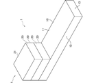
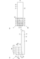
図1を参照して、実施形態における分離装置1の第1例について説明する。図1は、実施形態における分離装置1の第1例を示す斜視図である。図2は、実施形態における分離装置1の第1例を示す側面図である。また、各図において、共通する部分については、共通する参照符号を付し、重複する説明は適宜省略する。 (Embodiment of Separation Device 1)
A first example of theseparation device 1 according to the embodiment will be described with reference to FIG. FIG. 1 is a perspective view showing a first example of the separation device 1 in the embodiment. FIG. 2 is a side view showing a first example of the separation device 1 in the embodiment. Further, in each figure, common reference numerals are given to common parts, and duplicate description will be omitted as appropriate.
図1を参照して、実施形態における分離装置1の第1例について説明する。図1は、実施形態における分離装置1の第1例を示す斜視図である。図2は、実施形態における分離装置1の第1例を示す側面図である。また、各図において、共通する部分については、共通する参照符号を付し、重複する説明は適宜省略する。 (Embodiment of Separation Device 1)
A first example of the
分離装置1は、生体又は土壌から採取される採取物を含む液体状の検体から血清又は血漿を分離するためのものである。生体から採取される採取物としては、例えば、血液である。このとき、液体状の検体は、血液である。このほか、生体から採取される採取物としては、唾液、涙、汗、糞便、口腔粘膜細胞、鼻腔粘膜細胞等の粘膜細胞であってもよい。このとき、液体状の検体は、唾液、涙、汗であってもよい。
The separation device 1 is for separating serum or plasma from a liquid sample containing a sample collected from a living body or soil. The sample collected from the living body is, for example, blood. At this time, the liquid sample is blood. In addition, the collected material collected from the living body may be mucosal cells such as saliva, tears, sweat, feces, oral mucosal cells, and nasal mucosal cells. At this time, the liquid sample may be saliva, tears, or sweat.
また、生体又は土壌から採取される血液等の採取物を、マイクロチューブ等の所定の容器の中で、溶媒に溶解させてpH調整をし、液体状の検体としてもよい。溶媒としては、例えば、酢酸緩衝液(酢酸 + 酢酸ナトリウム)、リン酸緩衝液(リン酸 + リン酸ナトリウム)、クエン酸緩衝液(クエン酸 + クエン酸ナトリウム)、クエン酸リン酸緩衝液(クエン酸 + リン酸ナトリウム)、ホウ酸緩衝液、酒石酸緩衝液、トリス緩衝液、リン酸緩衝生理食塩水、マッキルベイン緩衝液、純水、スクロースPBSバッファー、界面活性剤入の純水等が用いられる。
Alternatively, a sample such as blood collected from a living body or soil may be dissolved in a solvent in a predetermined container such as a microtube to adjust the pH to prepare a liquid sample. Examples of the solvent include acetate buffer (acetate + sodium acetate), phosphate buffer (phosphate + sodium phosphate), citrate buffer (citrate + sodium citrate), citrate phosphate buffer (citrate). Acid + sodium phosphate), borate buffer, tartrate buffer, Tris buffer, phosphate buffer physiological saline, McIlvaine buffer, pure water, sucrose PBS buffer, pure water containing surfactant, etc. are used.
例えば、がん患者や糖尿病患者等から尿を採取物として採取する場合、溶媒を混ぜて液体状の検体とすることが好ましい。例えば、涙を採取物として採取する場合、涙に含まれるごみ等の不要物を除去した上で、溶媒を混ぜて液体状の検体としてもよい。例えば、土壌を採取物として採取する場合、土壌に含まれる砂粒等の不要物を除去した上で、溶媒を混ぜて液体状の検体としてもよい。例えば、糞便を採取物として採取する場合、溶媒を混ぜて、糞便に含まれる食物繊維等の不要物をろ紙等により除去した上で、液体状の検体としてもよい。
For example, when collecting urine as a sample from a cancer patient, a diabetic patient, etc., it is preferable to mix a solvent to prepare a liquid sample. For example, when tears are collected as a sample, unnecessary substances such as dust contained in the tears may be removed and then mixed with a solvent to prepare a liquid sample. For example, when the soil is collected as a sample, an unnecessary substance such as sand grains contained in the soil may be removed, and then a solvent may be mixed to prepare a liquid sample. For example, when stool is collected as a sample, a solvent may be mixed to remove unnecessary substances such as dietary fiber contained in the stool with a filter paper or the like, and then a liquid sample may be used.
以下、液体状の検体として、血液を例に説明する。分離装置1は、親水部10と、分離用フィルタ20と、を備える。分離用フィルタ20には、HUDSON法(化学処理と加熱により、血液等のサンプルに含まれるリボヌクレアーゼを不活性化し、ウイルス粒子等から核酸を抽出する手法)に必要な試薬や、RNase、DNase等の試薬や、バッファー(pH調整材料)など、血液に含まれる血球を分離するために必要な物質が含まれていてもよい。
Hereinafter, blood will be described as an example as a liquid sample. The separation device 1 includes a hydrophilic portion 10 and a separation filter 20. The separation filter 20 includes reagents necessary for the HUDSON method (a method of inactivating ribonuclease contained in a sample of blood or the like by chemical treatment and heating to extract nucleic acid from virus particles or the like), RNase, DNase, or the like. It may contain substances necessary for separating blood cells contained in blood, such as reagents and buffers (pH adjusting materials).
親水部10は、板状に形成される。親水部10は、親水性材料で構成される。親水部10は、親水性フィルムからなり、例えば、スリーエムジャパン株式会社製の9901P等が用いられる。親水部10は、プラスチックやガラス等の基材に、バイオミメティクスを利用した撥水表面構造を付加して、親水性材料としたものであってもよい。親水部10は、金属で構成されてもよい。親水部10は、親水性紙が用いられてもよい。
The hydrophilic portion 10 is formed in a plate shape. The hydrophilic portion 10 is made of a hydrophilic material. The hydrophilic portion 10 is made of a hydrophilic film, and for example, 9901P manufactured by 3M Japan Ltd. is used. The hydrophilic portion 10 may be made of a hydrophilic material by adding a water-repellent surface structure using biomimetics to a base material such as plastic or glass. The hydrophilic portion 10 may be made of metal. Hydrophilic paper may be used for the hydrophilic portion 10.
親水部10は、分離用フィルタ20が設けられる第1主面11と、第1主面11の反対側の第2主面12と、第1主面11と第2主面12とを繋ぐ端面13と、を有する。
The hydrophilic portion 10 is an end surface connecting the first main surface 11 on which the separation filter 20 is provided, the second main surface 12 on the opposite side of the first main surface 11, and the first main surface 11 and the second main surface 12. 13 and.
分離用フィルタ20は、中空糸又は多孔質材の何れかで構成される。分離用フィルタ20は、2つ積み重ねられて、親水部10の一部の領域に設けられる。分離用フィルタ20は、板状の親水部10の長手方向における端部に固着される。分離用フィルタ20は、親水部10の一部の領域に、1つ設けられてもよい。分離用フィルタ20は、親水部10の一部の領域に、2つ以上積み重ねられてもよい。
The separation filter 20 is made of either a hollow fiber or a porous material. Two separation filters 20 are stacked and provided in a part of the hydrophilic portion 10. The separation filter 20 is fixed to the end of the plate-shaped hydrophilic portion 10 in the longitudinal direction. One separation filter 20 may be provided in a part of the hydrophilic portion 10. Two or more separation filters 20 may be stacked in a part of the hydrophilic portion 10.
分離用フィルタ20は、第1主面21と、第1主面21の反対側の第2主面22と、第1主面21と第2主面22とを繋ぐ端面23と、を有する。第1主面21は、液体状の検体が滴下される面となる。第2主面22は、親水部10の一部の領域に設置される。
The separation filter 20 has a first main surface 21, a second main surface 22 on the opposite side of the first main surface 21, and an end surface 23 connecting the first main surface 21 and the second main surface 22. The first main surface 21 is a surface on which a liquid sample is dropped. The second main surface 22 is installed in a part of the hydrophilic portion 10.
この分離用フィルタ20を構成する材料の例を以下の表1、表2に示す。ちなみに下記の表1、表2は、具体例の更にその上位概念を記載している。上位概念に含まれるものであれば具体例に限定されるものではなく、他のいかなる材料を適用するようにしてもよい。
Examples of materials constituting the separation filter 20 are shown in Tables 1 and 2 below. Incidentally, Tables 1 and 2 below describe the higher-level concepts of the specific examples. As long as it is included in the superordinate concept, it is not limited to a specific example, and any other material may be applied.


分離用フィルタ20は、凝固防止剤又は生体物質が添加されていてもよい。凝固防止剤は、検体が血液の場合には、EDTA(エチレンジアミン四酢酸) 、ヘパリンナトリウム、クエン酸、シュウ酸、フッ化ナトリウム等である。凝固防止剤を添加することにより、この分離用フィルタ20内の凝固防止剤と混合することで、血液自体の凝固防止が可能となり、ひいては良好な測定が可能となる。
The separation filter 20 may be added with an anticoagulant or a biological substance. When the sample is blood, the anticoagulant is EDTA (ethylenediaminetetraacetic acid), sodium heparin, citric acid, oxalic acid, sodium fluoride and the like. By adding the anticoagulant, the blood itself can be prevented from coagulating by mixing with the anticoagulant in the separation filter 20, and thus good measurement becomes possible.
中でもフィブリノゲンは血液凝固に関わる物質であり、検出装置の目詰まりや、毛細管現象の妨げとなり、定量的な測定が難しく、微小な血液量での分析が困難である。
Among them, fibrinogen is a substance involved in blood coagulation, which hinders clogging of the detection device and capillarity, makes quantitative measurement difficult, and analysis with a minute blood volume is difficult.
このため、分離用フィルタ20は、フィブリノゲン除去または凝固防止のために、更に下記の内包物が添加されていてもよい。これにより、フィブリノゲンを吸収又は分解させることができ、血液凝固を防止し、検査を容易にすることができる。
Therefore, the following inclusions may be further added to the separation filter 20 in order to remove fibrinogen or prevent coagulation. Thereby, fibrinogen can be absorbed or decomposed, blood coagulation can be prevented, and the test can be facilitated.
この内包物の例としては、多官能アクリルアミドやスルホベタインモノマー等親水性モノマー及びその微粒子、ヒドロキシアパタイト(水産燐灰石) 、PEG系材料(PEG(Polyethylene glycol)、PPL-g-PEG copolymer、PEGが付加されている物質等)が含まれるものであってもよい。また、この内包物の例としては、酸化チタン、金、銀、酸化亜鉛、銅、酸化アルミニウム、酸化チタン等からなる金属ナノ粒子(直径5nm~500μm)、フィブリノゲン分解物質(フィブリノゲン)、プラスミノゲンアクチベータ(PA)、ワルファリン、アセノクマロール、フェニンジオン、抗ビタミンK阻害物質等クマリン誘導体物質、ダビガトラン、アルガトロバン等トロンビン阻害物質、リバーロキサバン、エドキサバン、アビキサバン、フォンダパリヌクス等凝固因子阻害物質、N-メチロールアクリルアミド、2-ヒドロキシエチルメタクリレート、アクリル酸をコモノマーとして用いた親水性モノマーの分散重合により構成される親水性ポリマー微粒子、1,4-シクロヘキサンジメタノールモノアクリレート、N-ビニルピロリドン、ゼオライト、金属錯体(PCP(多孔性金属錯体)、銅フタロシアニン、アゾメチン等)、ポリエステルゲルで構成されていてもよい。
Examples of this inclusion include hydrophilic monomers such as polyfunctional acrylamide and sulfobetaine monomers and their fine particles, hydroxyapatite (aquatic phosphoric stone), PEG-based materials (PEG (Polyethylene glycol), PPL-g-PEG copolymer, and PEG. It may contain substances (such as polyethylene glycol). Examples of the inclusions include metal nanoparticles (diameter 5 nm to 500 μm) composed of titanium oxide, gold, silver, zinc oxide, copper, aluminum oxide, titanium oxide and the like, fibrinogen degrading substances (fibrinogen), and plasminogen activators (. PA), Walfarin, Asenokumalol, Phenindione, Cumarin derivative substances such as antivitamin K inhibitor, Trombin inhibitors such as dabigatlan and argatroban, Riverloxaban, Edxaban, Abixaban, Fondaparinux and other coagulation factor inhibitors, N-polymer acrylamide , 2-Hydroxyethyl methacrylate, hydrophilic polymer fine particles composed of dispersion polymerization of hydrophilic monomer using acrylic acid as a comonomer, 1,4-cyclohexanedimethanol monoacrylate, N-vinylpyrrolidone, zeolite, metal complex (PCP) It may be composed of (porous metal complex), copper phthalocyanine, monomer, etc.) and polyester gel.
また検体がDNA(核酸)の場合には、デオキシリボヌクレアーゼによるDNA分解を防ぐために、DNA分解酵素阻害剤を凝固防止剤として添加するようにしてもよい。また検体がRNA(マイクロRNA、メッセンジャーRNA等)の場合には、リボヌクレアーゼ(エンドリボヌクレアーゼ、エキソリボヌクレアーゼ等)によるRNA分解を防止するために、RNA分解酵素阻害剤を凝固防止剤として添加するようにしてもよい。検体が唾液の場合には、唾液中の粘性のもとになるムチンというタンパク質を分解し、測定を円滑にするために、ムチン分解酵素を凝固防止剤として添加するようにしてもよい。
When the sample is DNA (nucleic acid), a DNA degrading enzyme inhibitor may be added as an anticoagulant in order to prevent DNA degradation by deoxyribonuclease. When the sample is RNA (microRNA, messenger RNA, etc.), an RNA-degrading enzyme inhibitor is added as an anticoagulant in order to prevent RNA degradation by ribonucleases (endoribonuclease, exoribonuclease, etc.). May be good. When the sample is saliva, a protein called mucin, which is a source of viscosity in saliva, may be decomposed, and a mucin-degrading enzyme may be added as an anticoagulant in order to facilitate the measurement.
次に、実施形態に係る分離装置1を用いて液体状の検体から血清又は血漿を分離する方法について説明する。図3は、実施形態における分離装置1の第1例を用いて液体状の検体から血清又は血漿を分離する方法を説明するための図である。
Next, a method for separating serum or plasma from a liquid sample using the separation device 1 according to the embodiment will be described. FIG. 3 is a diagram for explaining a method of separating serum or plasma from a liquid sample using the first example of the separation device 1 in the embodiment.
まずユーザは、被験者から血液を採取し、採取した血液を液体状の検体として分離用フィルタ20の第1主面21に所定量滴下する。この滴下された血液は、図3に示す矢印M方向に向けて、分離用フィルタ20内を毛細管現象に基づいて分離用フィルタ20の第2主面22や端面23に向けて流れていくこととなる。血液は、分離用フィルタ20を流れることにより、血清又は血漿が分離される。
First, the user collects blood from the subject, and drops a predetermined amount of the collected blood as a liquid sample onto the first main surface 21 of the separation filter 20. The dropped blood flows in the separation filter 20 toward the second main surface 22 and the end surface 23 of the separation filter 20 based on the capillary phenomenon in the direction of the arrow M shown in FIG. Become. The blood is separated from serum or plasma by flowing through the separation filter 20.
そして、親水部10は、親水性材料で構成される。これにより、親水部10に到達した血清又は血漿は、親水部10に吸収されることなく、端面23から親水部10上に流れることとなる。このため、血清又は血漿を液体の状態で取り出すことが可能となる。
And the hydrophilic part 10 is made of a hydrophilic material. As a result, the serum or plasma that has reached the hydrophilic portion 10 will flow from the end face 23 onto the hydrophilic portion 10 without being absorbed by the hydrophilic portion 10. Therefore, it is possible to take out serum or plasma in a liquid state.
液体の状態で取り出された血清又は血漿は、ピペット等の回収装置により回収することができる。
Serum or plasma taken out in a liquid state can be collected by a collecting device such as a pipette.
本実施形態によれば、親水性材料で構成される親水部10と、親水部10の一部の領域に設けられるとともに、中空糸又は多孔質材料で構成される分離用フィルタ20と、を備える。これにより、血清又は血漿は、親水部10に吸収されることなく、分離用フィルタ20の端面23から親水部10上に流れることとなる。このため、ユーザは、血清又は血漿を液体の状態で取り出すことが可能となる。
According to the present embodiment, the hydrophilic portion 10 made of a hydrophilic material and the separation filter 20 provided in a part of the hydrophilic portion 10 and made of a hollow fiber or a porous material are provided. .. As a result, the serum or plasma flows from the end face 23 of the separation filter 20 onto the hydrophilic portion 10 without being absorbed by the hydrophilic portion 10. Therefore, the user can take out serum or plasma in a liquid state.
図4は、実施形態における分離装置1の第2例を示す図である。
FIG. 4 is a diagram showing a second example of the separation device 1 in the embodiment.
本実施形態に係る分離装置1は、親水部10と、分離用フィルタ20と、を備える。親水部10は、板状に形成され、分離用フィルタ20から離間する方向に向けて第1主面11が下方に傾斜されて形成される。
The separation device 1 according to the present embodiment includes a hydrophilic portion 10 and a separation filter 20. The hydrophilic portion 10 is formed in a plate shape, and the first main surface 11 is formed so as to be inclined downward in a direction away from the separation filter 20.
本実施形態によれば、親水部10は、板状に形成され、分離用フィルタ20から離間する方向に向けて下方に傾斜されて形成される。これにより、分離用フィルタ20の端面23から流れてきた血清又は血漿は、親水部10の傾斜に沿って流れることになる。このため、ユーザは、液体の状態の血清又は血漿を効率良く取り出すことが可能となる。
According to the present embodiment, the hydrophilic portion 10 is formed in a plate shape and is formed so as to be inclined downward in a direction away from the separation filter 20. As a result, the serum or plasma flowing from the end face 23 of the separation filter 20 will flow along the inclination of the hydrophilic portion 10. Therefore, the user can efficiently take out serum or plasma in a liquid state.
図5(a)は、実施形態における分離装置1の第3例を示す平面図であり、図5(b)は、図5(a)の5A-5A断面図である。図6(a)は、実施形態における分離装置1の第4例を示す断面図であり、図6(b)は、実施形態における分離装置1の第5例を示す断面図である。
FIG. 5A is a plan view showing a third example of the separation device 1 in the embodiment, and FIG. 5B is a cross-sectional view taken along the line 5A-5A of FIG. 5A. FIG. 6A is a cross-sectional view showing a fourth example of the separation device 1 in the embodiment, and FIG. 6B is a cross-sectional view showing a fifth example of the separation device 1 in the embodiment.
本実施形態に係る分離装置1は、親水部10と、分離用フィルタ20と、を備える。親水部10は、板状に形成され、分離用フィルタ20から離間する方向に向けて延びる複数の溝14が形成される。複数の溝14は、板状の親水部10の長手方向に沿って、互いに平行に配置される。なお、溝14は、複数であってもよいし、1つであってもよい。
The separation device 1 according to the present embodiment includes a hydrophilic portion 10 and a separation filter 20. The hydrophilic portion 10 is formed in a plate shape, and a plurality of grooves 14 extending in a direction away from the separation filter 20 are formed. The plurality of grooves 14 are arranged parallel to each other along the longitudinal direction of the plate-shaped hydrophilic portion 10. The number of grooves 14 may be plural or one.
溝14は、図5(b)に示すように、平坦面となって形成される底面14aと、底面14aから鉛直上方に延びる一対の側面14bとを有する。また、溝14は、図6(a)に示すように、下方に向けて湾曲した湾曲面となって形成される底面14aと、底面14aから鉛直上方に延びる一対の側面14bとを有していてもよい。また、溝14は、図6(b)に示すように、一対の側面14bが下方に向かうにつれて互いに近づくように形成されてもよい。
As shown in FIG. 5B, the groove 14 has a bottom surface 14a formed as a flat surface and a pair of side surfaces 14b extending vertically upward from the bottom surface 14a. Further, as shown in FIG. 6A, the groove 14 has a bottom surface 14a formed as a curved surface curved downward, and a pair of side surfaces 14b extending vertically upward from the bottom surface 14a. You may. Further, as shown in FIG. 6B, the grooves 14 may be formed so that the pair of side surfaces 14b come closer to each other as they go downward.
本実施形態によれば、親水部10は、分離用フィルタ20から離間する方向に向けて延びる溝14が形成される。これにより、分離用フィルタ20の端面23から流れてきた血清又は血漿は、溝14に沿って流れることになる。このため、ユーザは、液体の状態の血清又は血漿を効率良く取り出すことが可能となる。
According to the present embodiment, the hydrophilic portion 10 is formed with a groove 14 extending in a direction away from the separation filter 20. As a result, the serum or plasma flowing from the end face 23 of the separation filter 20 will flow along the groove 14. Therefore, the user can efficiently take out serum or plasma in a liquid state.
図7は、実施形態における分離装置1の第6例を示す図である。
FIG. 7 is a diagram showing a sixth example of the separation device 1 in the embodiment.
本実施形態に係る分離装置1は、親水部10と、分離用フィルタ20と、を備える。親水部10は、板状に形成され、分離した血清又は血漿を収集するための収集部15を有する。収集部15は、第1主面11が凹部状に形成される。
The separation device 1 according to the present embodiment includes a hydrophilic portion 10 and a separation filter 20. The hydrophilic portion 10 is formed in a plate shape and has a collecting portion 15 for collecting separated serum or plasma. The first main surface 11 of the collecting unit 15 is formed in a concave shape.
本実施形態によれば、親水部10は、分離した血清又は血漿を収集するための収集部15を有する。これにより、端面23から流れてきた血清又は血漿は、収集部15に収集されることになる。このため、ユーザは、一度の回収作業で、多くの液体の状態の血清又は血漿を回収することが可能となる。
According to this embodiment, the hydrophilic part 10 has a collecting part 15 for collecting separated serum or plasma. As a result, the serum or plasma flowing from the end face 23 will be collected by the collecting unit 15. Therefore, the user can collect a large amount of serum or plasma in a liquid state with a single collection operation.
なお、図示は省略するが、親水部10が分離用フィルタ20から離間する方向に向けて下方に傾斜されて形成される場合には、親水部10の下端部側に収集部15が設けられることが好ましい。これにより、親水部10の傾斜に沿って流れる血清又は血漿を、収集部15において収集することができる。このため、ユーザは、液体の状態の血清又は血漿を効率良く取り出すことが可能となる。
Although not shown, when the hydrophilic portion 10 is formed so as to be inclined downward in a direction away from the separation filter 20, the collecting portion 15 is provided on the lower end side of the hydrophilic portion 10. Is preferable. Thereby, the serum or plasma flowing along the slope of the hydrophilic part 10 can be collected in the collecting part 15. Therefore, the user can efficiently take out serum or plasma in a liquid state.
なお、図示は省略するが、親水部10に溝14が形成される場合には、溝の長手方向の一端部側に分離用フィルタ20が設けられ、長手方向における一端部とは反対側の他端部側に、収集部15が設けられることが好ましい。これにより、溝14に沿って流れる血清又は血漿を、収集部15において収集することができる。このため、ユーザは、液体の状態の血清又は血漿を効率良く取り出すことが可能となる。
Although not shown, when the groove 14 is formed in the hydrophilic portion 10, the separation filter 20 is provided on one end side in the longitudinal direction of the groove, and the other side opposite to the one end portion in the longitudinal direction. It is preferable that the collecting unit 15 is provided on the end side. Thereby, the serum or plasma flowing along the groove 14 can be collected in the collecting unit 15. Therefore, the user can efficiently take out serum or plasma in a liquid state.
図8は、実施形態における分離装置1の第7例を示す図である。
FIG. 8 is a diagram showing a seventh example of the separation device 1 in the embodiment.
本実施形態に係る分離装置1は、親水部10と、分離用フィルタ20と、を備える。親水部10は、板状に形成され、分離した血清又は血漿を回収する回収装置9を嵌合するための嵌合部16を有する。嵌合部16は、回収装置9の先端部93が嵌合される形状に形成される。嵌合部16は、上方に向けて拡径される拡径部16aと、分離した血清又は血漿を取り込むための開口部16bと、を有する。
The separation device 1 according to the present embodiment includes a hydrophilic portion 10 and a separation filter 20. The hydrophilic portion 10 is formed in a plate shape and has a fitting portion 16 for fitting a recovery device 9 for collecting separated serum or plasma. The fitting portion 16 is formed in a shape in which the tip end portion 93 of the recovery device 9 is fitted. The fitting portion 16 has a diameter-expanded portion 16a whose diameter is expanded upward, and an opening 16b for taking in separated serum or plasma.
回収装置9は、血清又は血漿を回収することができるものであって、例えば、ピペット等が用いられる。回収装置9は、先端部93が嵌合部16の拡径部16aに嵌合される。
The recovery device 9 can recover serum or plasma, and for example, a pipette or the like is used. In the recovery device 9, the tip portion 93 is fitted to the enlarged diameter portion 16a of the fitting portion 16.
本実施形態によれば、親水部10は、分離した血清又は血漿を回収する回収装置9を嵌合するための嵌合部16を有する。これにより、分離用フィルタ20の端面23から流れてきた血清又は血漿は、開口部16bから嵌合部16の内部に取り込まれる。そして、取り込まれた嵌合部16に嵌合された回収装置9により回収することができる。このため、ユーザは、液体の状態の血清又は血漿を、安定した状態で回収することができ、効率良く回収することが可能となる。
According to the present embodiment, the hydrophilic portion 10 has a fitting portion 16 for fitting a recovery device 9 for collecting separated serum or plasma. As a result, the serum or plasma flowing from the end face 23 of the separation filter 20 is taken into the inside of the fitting portion 16 through the opening 16b. Then, it can be collected by the collecting device 9 fitted to the taken-in fitting portion 16. Therefore, the user can collect the serum or plasma in a liquid state in a stable state, and can efficiently collect the serum or plasma.
さらに、本実施形態によれば、嵌合部16は、上方に向けて拡径される拡径部16aを有する。これにより、回収装置9の先端部93を嵌合部16の拡径部16aに挿入し易くすることができる。このため、ユーザは、液体の状態の血清又は血漿を回収する作業を、効率良く行うことが可能となる。
Further, according to the present embodiment, the fitting portion 16 has a diameter-expanded portion 16a whose diameter is expanded upward. As a result, the tip portion 93 of the recovery device 9 can be easily inserted into the enlarged diameter portion 16a of the fitting portion 16. Therefore, the user can efficiently perform the work of collecting serum or plasma in a liquid state.
なお、図示は省略するが、親水部10に収集部15が設けられる場合には、収集部15に嵌合部16が設けられることが好ましい。これにより、収集部15に収集された血清又は血漿を、嵌合部16に嵌め込まれた回収装置9により回収することができる。このため、ユーザは、液体の状態の血清又は血漿を回収する作業を、効率良く行うことが可能となる。
Although not shown, when the hydrophilic portion 10 is provided with the collecting portion 15, it is preferable that the collecting portion 15 is provided with the fitting portion 16. As a result, the serum or plasma collected in the collecting unit 15 can be collected by the collecting device 9 fitted in the fitting unit 16. Therefore, the user can efficiently perform the work of collecting serum or plasma in a liquid state.
図9(a)は、実施形態における分離装置1の第8例を示す側面図であり、図9(b)は、図9(a)の9A-9A断面図である。
9 (a) is a side view showing an eighth example of the separation device 1 in the embodiment, and FIG. 9 (b) is a sectional view taken along the line 9A-9A of FIG. 9 (a).
本実施形態に係る分離装置1は、親水部10と、分離用フィルタ20と、支持部材90と、を備える。
The separation device 1 according to the present embodiment includes a hydrophilic portion 10, a separation filter 20, and a support member 90.
支持部材90は、分離用フィルタ20を親水部10に支持するものである。支持部材90は、親水部10の第1主面11から上方に突出させて設けられる。支持部材90は、複数(図9中では、20個)の突起部91を備える。支持部材90は、複数の突起部91が親水部10の長手方向及び短手方向に所定の間隔を空けて並べて配置される。
The support member 90 supports the separation filter 20 on the hydrophilic portion 10. The support member 90 is provided so as to project upward from the first main surface 11 of the hydrophilic portion 10. The support member 90 includes a plurality of (20 in FIG. 9) protrusions 91. In the support member 90, a plurality of protrusions 91 are arranged side by side at predetermined intervals in the longitudinal direction and the lateral direction of the hydrophilic portion 10.
突起部91は、例えば、プラスチック製、金属製等で構成される。突起部91は、角柱状に形成される。突起部91は、円柱状、円筒状、各筒状等の形状に形成されてもよい。突起部91は、上下方向に積層された2つの分離用フィルタ20にそれぞれ挿通される。これにより、支持部材90は、分離用フィルタ20を親水部10に支持することができる。
The protrusion 91 is made of, for example, plastic, metal, or the like. The protrusion 91 is formed in a prismatic shape. The protrusion 91 may be formed in a cylindrical shape, a cylindrical shape, a tubular shape, or the like. The protrusion 91 is inserted into each of the two separation filters 20 stacked in the vertical direction. As a result, the support member 90 can support the separation filter 20 on the hydrophilic portion 10.
本実施形態によれば、分離用フィルタ20を親水部10に支持する支持部材90を更に備える。これにより、分離用フィルタ20を親水部10に対して支持することができる。このため、液体状の検体を分離用フィルタ20に滴下する際に、分離用フィルタ20が親水部10に対してずれるのを防止することができ、ユーザは、効率良く作業を行うことが可能となる。
According to this embodiment, a support member 90 that supports the separation filter 20 on the hydrophilic portion 10 is further provided. Thereby, the separation filter 20 can be supported with respect to the hydrophilic portion 10. Therefore, when the liquid sample is dropped on the separation filter 20, it is possible to prevent the separation filter 20 from shifting with respect to the hydrophilic portion 10, and the user can perform the work efficiently. Become.
本実施形態によれば、支持部材90は、分離用フィルタ20に挿通される突起部91を有する。これにより、分離用フィルタ20を親水部10に対して支持することができる。このため、液体状の検体を分離用フィルタ20に滴下する際に、分離用フィルタ20が親水部10に対してずれるのを一層防止することができ、ユーザは、効率良く作業を行うことが可能となる。
According to this embodiment, the support member 90 has a protrusion 91 that is inserted into the separation filter 20. Thereby, the separation filter 20 can be supported with respect to the hydrophilic portion 10. Therefore, when the liquid sample is dropped onto the separation filter 20, it is possible to further prevent the separation filter 20 from shifting with respect to the hydrophilic portion 10, and the user can perform the work efficiently. It becomes.
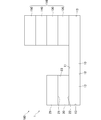
図10(a)は、実施形態における分離装置1の第9例を示す側面図であり、図10(b)は、実施形態における分離装置1の第9例を示す平面図である。
FIG. 10A is a side view showing a ninth example of the separation device 1 in the embodiment, and FIG. 10B is a plan view showing the ninth example of the separation device 1 in the embodiment.
本実施形態に係る分離装置1は、親水部10と、分離用フィルタ20と、支持部材90と、を備える。
The separation device 1 according to the present embodiment includes a hydrophilic portion 10, a separation filter 20, and a support member 90.
支持部材90は、分離用フィルタ20を親水部10に支持するものである。支持部材90は、親水部10の第1主面11から上方に突出させて設けられる。支持部材90は、複数(図10中では、4個)の挟持部92を備える。支持部材90は、挟持部92が平面視において分離用フィルタ20の4つの隅部に配置される。支持部材90は、複数の挟持部92により分離用フィルタ20を挟んで支持するものとなる。
The support member 90 supports the separation filter 20 on the hydrophilic portion 10. The support member 90 is provided so as to project upward from the first main surface 11 of the hydrophilic portion 10. The support member 90 includes a plurality of (four in FIG. 10) holding portions 92. In the support member 90, the sandwiching portion 92 is arranged at the four corners of the separation filter 20 in a plan view. The support member 90 is supported by sandwiching the separation filter 20 by a plurality of sandwiching portions 92.
挟持部92は、例えば、プラスチック製、金属製等で構成される。挟持部92は、第1主面11から上下方向に延びて形成され、平面視において断面L字状に形成される。挟持部91は、角柱状、円柱状、円筒状、各筒状等の形状に形成されてもよい。複数の挟持部92は、上下方向に積層された2つの分離用フィルタ20を側方から挟んで固定するものとなる。これにより、支持部材90は、分離用フィルタ20を親水部10に支持することができる。
The sandwiching portion 92 is made of, for example, plastic, metal, or the like. The sandwiching portion 92 is formed so as to extend in the vertical direction from the first main surface 11 and has an L-shaped cross section in a plan view. The sandwiching portion 91 may be formed in a shape such as a prismatic shape, a cylindrical shape, a cylindrical shape, or a tubular shape. The plurality of sandwiching portions 92 sandwich and fix the two separation filters 20 stacked in the vertical direction from the side. As a result, the support member 90 can support the separation filter 20 on the hydrophilic portion 10.
本実施形態によれば、分離用フィルタ20を親水部10に支持する支持部材90を更に備える。これにより、分離用フィルタ20を親水部10に対して支持することができる。このため、液体状の検体を分離用フィルタ20に滴下する際に、分離用フィルタ20が親水部10に対してずれるのを防止することができ、ユーザは、効率良く作業を行うことが可能となる。
According to this embodiment, a support member 90 that supports the separation filter 20 on the hydrophilic portion 10 is further provided. Thereby, the separation filter 20 can be supported with respect to the hydrophilic portion 10. Therefore, when the liquid sample is dropped on the separation filter 20, it is possible to prevent the separation filter 20 from shifting with respect to the hydrophilic portion 10, and the user can perform the work efficiently. Become.
本実施形態によれば、支持部材90は、分離用フィルタ20を挟んで支持する挟持部92を有する。これにより、分離用フィルタ20を親水部10に対して支持することができる。このため、液体状の検体を分離用フィルタ20に滴下する際に、分離用フィルタ20が親水部10に対してずれるのを一層防止することができ、ユーザは、効率良く作業を行うことが可能となる。
According to the present embodiment, the support member 90 has a holding portion 92 that sandwiches and supports the separation filter 20. Thereby, the separation filter 20 can be supported with respect to the hydrophilic portion 10. Therefore, when the liquid sample is dropped onto the separation filter 20, it is possible to further prevent the separation filter 20 from shifting with respect to the hydrophilic portion 10, and the user can perform the work efficiently. It becomes.
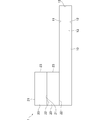
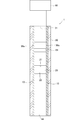
図11を参照して、実施形態における分離装置1の第10例について説明する。図11は、実施形態における分離装置1の第10例を示す図である。
A tenth example of the separation device 1 in the embodiment will be described with reference to FIG. FIG. 11 is a diagram showing a tenth example of the separation device 1 in the embodiment.
本実施形態に係る分離装置1は、親水部10と、分離用フィルタ20と、基材30と、を備える。
The separation device 1 according to the present embodiment includes a hydrophilic portion 10, a separation filter 20, and a base material 30.
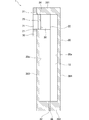
基材30は、円筒状に形成され、一方側の端部に形成される注入口31と、注入口31とは反対側に形成される回収口32と、を有する。基材30は、例えば、ガラス、プラスチック、金属等が用いられる。
The base material 30 has an injection port 31 formed in a cylindrical shape and formed at one end, and a collection port 32 formed on the opposite side of the injection port 31. As the base material 30, for example, glass, plastic, metal or the like is used.
分離用フィルタ20は、回収口32から離間して基材30の内部に配置される。第1主面21は、注入口31側に配置され、第2主面22は、回収口32側に配置される。端面23は、親水部10の一部の領域に設けられる。
The separation filter 20 is arranged inside the base material 30 away from the collection port 32. The first main surface 21 is arranged on the injection port 31 side, and the second main surface 22 is arranged on the collection port 32 side. The end face 23 is provided in a part of the hydrophilic portion 10.
親水部10は、注入口31から回収口32までの内面30aに設けられる。
The hydrophilic portion 10 is provided on the inner surface 30a from the injection port 31 to the collection port 32.
次に、本実施形態に係る分離装置1を用いて液体状の検体から血清又は血漿を分離する方法について説明する。図12は、実施形態における分離装置1の第10例を用いて液体状の検体から血清又は血漿を分離する方法を説明するための図である。
Next, a method for separating serum or plasma from a liquid sample using the separation device 1 according to the present embodiment will be described. FIG. 12 is a diagram for explaining a method of separating serum or plasma from a liquid sample using the tenth example of the separation device 1 in the embodiment.
まずユーザは、被験者から血液を採取し、採取した血液を液体状の検体として、注入口31から血液を注入する。そして、注入された血液は、分離用フィルタ20の第1主面21に所定量滴下される。この滴下された血液は、図12に示す矢印M方向に向けて、分離用フィルタ20内を毛細管現象に基づいて分離用フィルタ20の第2主面22に向けて流れていくこととなる。血液は、分離用フィルタ20を流れることにより、血漿又は血清が分離される。
First, the user collects blood from the subject, uses the collected blood as a liquid sample, and injects blood from the injection port 31. Then, a predetermined amount of the injected blood is dropped onto the first main surface 21 of the separation filter 20. The dropped blood flows in the separation filter 20 toward the second main surface 22 of the separation filter 20 based on the capillary phenomenon in the direction of the arrow M shown in FIG. Plasma or serum is separated from blood by flowing through the separation filter 20.
そして、親水部10は、親水性材料で構成される。これにより、親水部10に到達した血清又は血漿は、親水部10に吸収されることなく、分離用フィルタ20の第2主面22から親水部10上に流れることとなる。このため、血清又は血漿を液体の状態で取り出すことが可能となる。
And the hydrophilic part 10 is made of a hydrophilic material. As a result, the serum or plasma that has reached the hydrophilic portion 10 will flow from the second main surface 22 of the separation filter 20 onto the hydrophilic portion 10 without being absorbed by the hydrophilic portion 10. Therefore, it is possible to take out serum or plasma in a liquid state.
その後、予め回収口32の下方側に用意した保管容器8に、液体の状態で取り出された血清又は血漿を収集する。
After that, the serum or plasma taken out in a liquid state is collected in the storage container 8 prepared in advance on the lower side of the collection port 32.
本実施形態によれば、筒状に形成される基材30を更に備え、基材30は、一方側の端部に形成される注入口31と、注入口31とは反対側に形成される回収口32と、を有し、親水部10は、基材30の内面に設けられ、分離用フィルタ20は、回収口32から離間して基材30の内部に配置される。これにより、血清又は血漿は、親水部10に吸収されることなく、分離用フィルタ20の第2主面22から親水部10上に流れることとなる。このため、ユーザは、血清又は血漿を液体の状態で取り出すことが可能となる。
According to the present embodiment, the base material 30 formed in a tubular shape is further provided, and the base material 30 is formed on one side of the injection port 31 and on the opposite side of the injection port 31. The collection port 32 and the hydrophilic portion 10 are provided on the inner surface of the base material 30, and the separation filter 20 is arranged inside the base material 30 away from the recovery port 32. As a result, the serum or plasma flows from the second main surface 22 of the separation filter 20 onto the hydrophilic portion 10 without being absorbed by the hydrophilic portion 10. Therefore, the user can take out serum or plasma in a liquid state.
また、本実施形態によれば、基材30は、筒状に形成されるため、分離した血清又は血漿が、基材30の外側に漏れるのを防止することができる。このため、血清又は血漿を効率よく収集することができる。
Further, according to the present embodiment, since the base material 30 is formed in a tubular shape, it is possible to prevent the separated serum or plasma from leaking to the outside of the base material 30. Therefore, serum or plasma can be efficiently collected.
図13は、実施形態における分離装置1の第11例を示す図である。
FIG. 13 is a diagram showing an eleventh example of the separation device 1 in the embodiment.
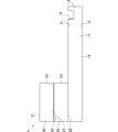
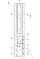
本実施形態に係る分離装置1は、親水部10と、分離用フィルタ20と、基材30と、疎水部40と、を備える。
The separation device 1 according to the present embodiment includes a hydrophilic portion 10, a separation filter 20, a base material 30, and a hydrophobic portion 40.
親水部10は、注入口31から回収口32側の内面30aに設けられる。
The hydrophilic portion 10 is provided on the inner surface 30a on the side of the collection port 32 from the injection port 31.
基材30は、回収口32側の内面30aの端部に、疎水部40が塗布等により設けられる。基材30の内径は、十分に小さく、分離した血清又は血漿が基材30の内部において毛細管現象が展開される程度の径で構成され、例えば7mm以下が好ましい。
The base material 30 is provided with a hydrophobic portion 40 by coating or the like at the end of the inner surface 30a on the recovery port 32 side. The inner diameter of the base material 30 is sufficiently small, and is composed of a diameter such that the separated serum or plasma develops a capillary phenomenon inside the base material 30, and is preferably 7 mm or less, for example.
基材30は、注入口31から回収口32まで、内径がほぼ同一径となって形成される。なお、図示は省略するが、基材30は、内面30aがテーパー状に形成されて、注入口31の内径が、回収口32の内径よりも大きく形成されてもよい。
The base material 30 is formed from the injection port 31 to the recovery port 32 with substantially the same inner diameter. Although not shown, the base material 30 may have an inner surface 30a formed in a tapered shape so that the inner diameter of the injection port 31 is larger than the inner diameter of the recovery port 32.
疎水部40は、疎水性材料で構成される。疎水性材料としては、例えば、ポリエチレン、ポリプロピレン、ポリイミド、SU-8、レジスト、フッ素樹脂、疎水性ガラスなどがある。また、表面の親水処理方法としてプラズマ処理、表面凹凸構造をレーザーやエッチング処理で形成することにより、疎水性の機能を疎水部表面に付加させたものが用いられる。
The hydrophobic part 40 is made of a hydrophobic material. Examples of the hydrophobic material include polyethylene, polypropylene, polyimide, SU-8, resist, fluororesin, and hydrophobic glass. Further, as a surface hydrophilic treatment method, a method in which a hydrophobic function is added to the surface of a hydrophobic portion by forming a surface uneven structure by plasma treatment or laser or etching treatment is used.
次に、実施形態に係る分離装置1を用いて液体状の検体から血清又は血漿を分離する方法について説明する。図14は、実施形態における分離装置1の第11例を用いて液体状の検体から血清又は血漿を分離する方法を説明するための図である。
Next, a method for separating serum or plasma from a liquid sample using the separation device 1 according to the embodiment will be described. FIG. 14 is a diagram for explaining a method of separating serum or plasma from a liquid sample using the eleventh example of the separation device 1 in the embodiment.
ユーザは、血液を被験者から採取し、採取した血液を液体状の検体として、注入口31から血液を注入する。そして、注入された血液は、分離用フィルタ20の第1主面21に所定量滴下される。この滴下された血液は、図14に示す矢印M方向に向けて分離用フィルタ20内を毛細管現象に基づいて分離用フィルタ20の第2主面22に向けて流れていくこととなる。血液は、分離用フィルタ20を流れることにより、血漿又は血清が分離される。
The user collects blood from the subject, uses the collected blood as a liquid sample, and injects blood from the injection port 31. Then, a predetermined amount of the injected blood is dropped onto the first main surface 21 of the separation filter 20. The dropped blood flows in the separation filter 20 in the direction of the arrow M shown in FIG. 14 toward the second main surface 22 of the separation filter 20 based on the capillary phenomenon. Plasma or serum is separated from blood by flowing through the separation filter 20.
そして、親水部10は、親水性材料で構成される。これにより、親水部10に到達した血清又は血漿は、親水部10に吸収されることなく、第2主面22から親水部10上に流れることとなる。このため、血清又は血漿を液体の状態で取り出すことが可能となる。
And the hydrophilic part 10 is made of a hydrophilic material. As a result, the serum or plasma that has reached the hydrophilic portion 10 will flow from the second main surface 22 onto the hydrophilic portion 10 without being absorbed by the hydrophilic portion 10. Therefore, it is possible to take out serum or plasma in a liquid state.
そして、本実施形態では、基材30の回収口32側の内面30aの端部に、疎水性材料で構成される疎水部40を備える。これにより、血清又は血漿と、疎水部40との接触角が大きくなる。このため、血清又は血漿は、基材30の内部における分離用フィルタ20から疎水部40までの間の空間Vに、収集されることとなる。すなわち、血清又は血漿は、回収口32側から基材30の外側に流れ出さないものとなる。
Then, in the present embodiment, a hydrophobic portion 40 made of a hydrophobic material is provided at the end of the inner surface 30a on the recovery port 32 side of the base material 30. As a result, the contact angle between the serum or plasma and the hydrophobic portion 40 is increased. Therefore, the serum or plasma is collected in the space V between the separation filter 20 and the hydrophobic portion 40 inside the base material 30. That is, the serum or plasma does not flow out from the collection port 32 side to the outside of the base material 30.
本実施形態によれば、回収口32側の基材30の内面30aの端部に、疎水性材料で構成される疎水部40を更に備える。これにより、分離した血清又は血漿が、基材30の内部における分離用フィルタ20から疎水部40までの間の空間Vに、収集される。このため、血清又は血漿を効率よく回収することができる。
According to the present embodiment, a hydrophobic portion 40 made of a hydrophobic material is further provided at the end of the inner surface 30a of the base material 30 on the recovery port 32 side. As a result, the separated serum or plasma is collected in the space V between the separation filter 20 and the hydrophobic portion 40 inside the base material 30. Therefore, serum or plasma can be efficiently collected.
図15は、実施形態における分離装置1の第12例を示す図である。
FIG. 15 is a diagram showing a twelfth example of the separation device 1 in the embodiment.
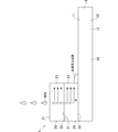
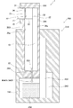
本実施形態に係る分離装置1は、親水部10と、分離用フィルタ20と、基材30と、吸引部50と、を備える。
The separation device 1 according to the present embodiment includes a hydrophilic portion 10, a separation filter 20, a base material 30, and a suction portion 50.
吸引部50は、回収口32側に設けられ、回収口32側から基材30の内部の空気を吸引するためのものである。吸引部50は、回収口32に対して着脱自在である。吸引部50は、基材30の内面30aの親水部10に沿って、分離用フィルタ20から回収口32側に向けて移動可能なピストン等が用いられる。
The suction unit 50 is provided on the recovery port 32 side and is for sucking the air inside the base material 30 from the recovery port 32 side. The suction unit 50 is removable from the collection port 32. As the suction portion 50, a piston or the like that can move from the separation filter 20 toward the collection port 32 side along the hydrophilic portion 10 of the inner surface 30a of the base material 30 is used.
次に、実施形態に係る分離装置1を用いて液体状の検体から血清又は血漿を分離する方法について説明する。図16は、実施形態における分離装置1の第12例を用いて液体状の検体から血清又は血漿を分離する方法を説明するための図である。
Next, a method for separating serum or plasma from a liquid sample using the separation device 1 according to the embodiment will be described. FIG. 16 is a diagram for explaining a method of separating serum or plasma from a liquid sample using the twelfth example of the separation device 1 in the embodiment.
ユーザは、被験者から血液を採取し、採取した血液を液体状の検体として、血液を容器59に入れておき、容器59内の血液に注入口31を接触させる。そして、分離用フィルタ20近傍に配置された吸引部50を、回収口32側に向けて図中矢印N方向に、基材30の内面30aの親水部10に沿ってスライドさせる。これにより、注入口31から基材30の内部に血液が注入される。そして、注入された血液は、分離用フィルタ20の第1主面21に到達する。到達した血液は、図16に示す矢印M方向に向けて分離用フィルタ20内を毛細管現象に基づいて分離用フィルタ20の第2主面22に向けて流れていくこととなる。血液は、分離用フィルタ20を流れることにより、血漿又は血清が分離される。
The user collects blood from the subject, uses the collected blood as a liquid sample, puts the blood in the container 59, and brings the injection port 31 into contact with the blood in the container 59. Then, the suction portion 50 arranged in the vicinity of the separation filter 20 is slid toward the recovery port 32 side in the direction of arrow N in the drawing along the hydrophilic portion 10 of the inner surface 30a of the base material 30. As a result, blood is injected into the base material 30 from the injection port 31. Then, the injected blood reaches the first main surface 21 of the separation filter 20. The arriving blood flows in the separation filter 20 in the direction of the arrow M shown in FIG. 16 toward the second main surface 22 of the separation filter 20 based on the capillary phenomenon. Plasma or serum is separated from blood by flowing through the separation filter 20.
そして、親水部10は、親水性材料で構成される。これにより、親水部10に到達した血清又は血漿は、親水部10に吸収されることなく、第2主面22から親水部10上に流れることとなる。このため、血清又は血漿を液体の状態で取り出すことが可能となる。
And the hydrophilic part 10 is made of a hydrophilic material. As a result, the serum or plasma that has reached the hydrophilic portion 10 will flow from the second main surface 22 onto the hydrophilic portion 10 without being absorbed by the hydrophilic portion 10. Therefore, it is possible to take out serum or plasma in a liquid state.
本実施形態によれば、回収口32側から基材30の内部の空気を吸引するための吸引部50を更に備える。これにより、分離用フィルタ20を流れる血液の毛細管現象が促進され、血液から血清又は血漿をより早く分離させることができる。このため、血清又は血漿をより効率良く取り出すことが可能となる。
According to the present embodiment, a suction unit 50 for sucking the air inside the base material 30 from the recovery port 32 side is further provided. As a result, the capillary phenomenon of blood flowing through the separation filter 20 is promoted, and serum or plasma can be separated from blood more quickly. Therefore, serum or plasma can be taken out more efficiently.
図17は、実施形態における分離装置1の第13例を示す図である。
FIG. 17 is a diagram showing a thirteenth example of the separation device 1 in the embodiment.
本実施形態に係る分離装置1は、親水部10と、分離用フィルタ20と、基材30と、送気部60と、を備える。
The separation device 1 according to the present embodiment includes a hydrophilic portion 10, a separation filter 20, a base material 30, and an air supply portion 60.
送気部60は、注入口31側に設けられ、注入口31側から基材30の内部の空気を送るためのものである。送気部60は、注入口31に対して着脱自在である。送気部60は、基材30の内面30aの親水部10に沿って、注入口31側から分離用フィルタ20に向けて移動可能なピストン等が用いられる。
The air supply unit 60 is provided on the injection port 31 side, and is for sending the air inside the base material 30 from the injection port 31 side. The air supply unit 60 is removable from the injection port 31. As the air supply unit 60, a piston or the like that can move from the injection port 31 side toward the separation filter 20 along the hydrophilic portion 10 of the inner surface 30a of the base material 30 is used.
また、注入口31から分離用フィルタ20までの間の基材30の内部の空間には、透過フィルタ61が設けられる。透過フィルタ61は、液体状の検体及び空気等の気体が透過可能なものであり、例えば、ポリプロピレンを主な構成とするフィルム、ポリエチレンを主な構成とするフィルム、ポリオレフィンを主な構成とするフィルム、多孔質フィルム、PTFEメンブレンフィルム、日東電工株式会社製の超高分子量ポリエチレン多孔質フィルム、日東電工株式会社製のサンマップ(登録商標)、日東電工株式会社製の通気性シート ブレスロン(登録商標)、日東電工株式会社製の通気性粘着テープ ニトスルー(登録商標)、三菱ケミカル株式会社製の透湿性フィルムKTF、三菱ケミカル株式会社製の透湿通気防水フィルムエクセポール(登録商標)、スリーエムジャパン株式会社製の「マイクロポーラスフィルム」、株式会社トクヤマ製の微多孔質フィルム「NFシート」、帝人株式会社製のミライム等が用いられる。
Further, a transmission filter 61 is provided in the space inside the base material 30 between the injection port 31 and the separation filter 20. The permeation filter 61 is capable of permeating a liquid sample and a gas such as air. For example, a film mainly composed of polypropylene, a film mainly composed of polyethylene, and a film mainly composed of polyolefin. , Porous film, PTFE membrane film, Ultra-high molecular weight polyethylene porous film manufactured by Nitto Denko Co., Ltd., Sunmap (registered trademark) manufactured by Nitto Denko Co., Ltd., Breathlon (registered trademark) manufactured by Nitto Denko Co., Ltd. , Nitto Denko Co., Ltd. breathable adhesive tape Nitothru (registered trademark), Mitsubishi Chemical Co., Ltd. breathable film KTF, Mitsubishi Chemical Co., Ltd. breathable breathable waterproof film Excelpol (registered trademark), 3M Japan Co., Ltd. "Microporous film" manufactured by Tokuyama Co., Ltd., microporous film "NF sheet" manufactured by Tokuyama Co., Ltd., Milime manufactured by Teijin Co., Ltd., etc. are used.
次に、実施形態に係る分離装置1を用いて液体状の検体から血清又は血漿を分離する方法について説明する。図18は、実施形態における分離装置1の第13例を用いて液体状の検体から血清又は血漿を分離する方法を説明するための図であって、図18(a)は、液体状の検体を注入口31に注入した状態を示す図であり、図18(b)は、液体状の検体から血清又は血漿を分離した状態を示す図である。
Next, a method for separating serum or plasma from a liquid sample using the separation device 1 according to the embodiment will be described. FIG. 18 is a diagram for explaining a method of separating serum or plasma from a liquid sample using the thirteenth example of the separation device 1 in the embodiment, and FIG. 18 (a) is a diagram for explaining a method for separating serum or plasma from the liquid sample. Is a diagram showing a state in which serum or plasma is injected into the injection port 31, and FIG. 18B is a diagram showing a state in which serum or plasma is separated from a liquid sample.
ユーザは、被験者から血液を採取し、採取した血液を液体状の検体として、注入口31から血液を注入する。そして、注入された血液は、分離用フィルタ20の第1主面21に所定量滴下される。そして、ユーザは、注入口31側に送気部60を配置する。ユーザは、配置された送気部60を、分離用フィルタ20側に向けて基材30の内面30aに沿ってスライドさせる。これにより、血液は、図18(b)に示す矢印M方向に向けて、分離用フィルタ20内を毛細管現象に基づいて第2主面22に向けて流れていくこととなる。血液は、分離用フィルタ20を流れることにより、血漿又は血清が分離される。
The user collects blood from the subject, uses the collected blood as a liquid sample, and injects blood from the injection port 31. Then, a predetermined amount of the injected blood is dropped onto the first main surface 21 of the separation filter 20. Then, the user arranges the air supply unit 60 on the injection port 31 side. The user slides the arranged air supply unit 60 toward the separation filter 20 side along the inner surface 30a of the base material 30. As a result, the blood flows in the separation filter 20 toward the second main surface 22 based on the capillary phenomenon in the direction of the arrow M shown in FIG. 18 (b). Plasma or serum is separated from blood by flowing through the separation filter 20.
そして、親水部10は、親水性材料で構成される。これにより、親水部10に到達した血清又は血漿は、親水部10に吸収されることなく、第2主面22から親水部10上に流れることとなる。このため、血清又は血漿を液体の状態で取り出すことが可能となる。
And the hydrophilic part 10 is made of a hydrophilic material. As a result, the serum or plasma that has reached the hydrophilic portion 10 will flow from the second main surface 22 onto the hydrophilic portion 10 without being absorbed by the hydrophilic portion 10. Therefore, it is possible to take out serum or plasma in a liquid state.
その後、予め回収口32の下方側に用意した保管容器8に、液体の状態で取り出された血清又は血漿を収集する。
After that, the serum or plasma taken out in a liquid state is collected in the storage container 8 prepared in advance on the lower side of the collection port 32.
本実施形態によれば、注入口31側から基材30の内部に空気を送る送気部60を更に備える。これにより、分離用フィルタ20を流れる血液の毛細管現象が促進され、血液から血清又は血漿をより早く分離させることができる。このため、血清又は血漿をより効率良く取り出すことが可能となる。
According to this embodiment, an air supply unit 60 for sending air from the injection port 31 side to the inside of the base material 30 is further provided. As a result, the capillary phenomenon of blood flowing through the separation filter 20 is promoted, and serum or plasma can be separated from blood more quickly. Therefore, serum or plasma can be taken out more efficiently.
本実施形態によれば、注入口31から分離用フィルタ20までの間の基材30の内部の空間に、透過フィルタ61が設けられる。これにより、送気部60により基材30の内部に送られる空気のチリや埃等の不要物を除去することができ、分離用フィルタ20に送られる空気を清浄することができる。このため、血液に不要物が混ざるのを防止することができ、血清又は血漿をより効率よく取り出すことが可能となる。
According to this embodiment, the transmission filter 61 is provided in the space inside the base material 30 between the injection port 31 and the separation filter 20. As a result, unnecessary substances such as dust and dirt in the air sent to the inside of the base material 30 can be removed by the air supply unit 60, and the air sent to the separation filter 20 can be purified. Therefore, it is possible to prevent unnecessary substances from being mixed with blood, and it is possible to take out serum or plasma more efficiently.
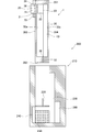
(検出装置100の実施形態)
図19を参照して、実施形態における検出装置100の第1例について説明する。図19は、実施形態における検出装置100の第1例を示す図である。 (Embodiment of Detection Device 100)
A first example of thedetection device 100 according to the embodiment will be described with reference to FIG. FIG. 19 is a diagram showing a first example of the detection device 100 in the embodiment.
図19を参照して、実施形態における検出装置100の第1例について説明する。図19は、実施形態における検出装置100の第1例を示す図である。 (Embodiment of Detection Device 100)
A first example of the
検出装置100は、生体物質を検出するためのものである。検出装置100は、分離装置1と、検出部110とを備える。分離装置1は、親水部10と、分離用フィルタ20と、を備える。
The detection device 100 is for detecting a biological substance. The detection device 100 includes a separation device 1 and a detection unit 110. The separation device 1 includes a hydrophilic portion 10 and a separation filter 20.
親水部10は、板状に形成される。親水部10は、親水性材料で構成される。親水部10は、親水性フィルムからなる。親水部10は、分離用フィルタ20が設けられる第1主面11と、第1主面11とは反対側の第2主面12と、第1主面11と第2主面12とを繋ぐ端面13と、を有する。
The hydrophilic portion 10 is formed in a plate shape. The hydrophilic portion 10 is made of a hydrophilic material. The hydrophilic portion 10 is made of a hydrophilic film. The hydrophilic portion 10 connects the first main surface 11 on which the separation filter 20 is provided, the second main surface 12 on the side opposite to the first main surface 11, and the first main surface 11 and the second main surface 12. It has an end face 13.
分離用フィルタ20は、中空糸又は多孔質材の何れかで構成される。分離用フィルタ20は、親水部10の一部の領域に設けられる。
The separation filter 20 is made of either a hollow fiber or a porous material. The separation filter 20 is provided in a part of the hydrophilic portion 10.
分離用フィルタ20は、第1主面21に、吸収材25を有する。吸収材25は、ポリウレタン等の合成樹脂が発泡成形されるスポンジ等が用いられる。分離用フィルタ20は、第2主面22が親水部10の一部の領域に設置される。
The separation filter 20 has an absorbent material 25 on the first main surface 21. As the absorbent material 25, a sponge or the like in which a synthetic resin such as polyurethane is foam-molded is used. In the separation filter 20, the second main surface 22 is installed in a part of the hydrophilic portion 10.
検出部110は、分離装置1から分離した血清又は血漿から生体物質を検出する。生体物質は、例えば、グルコースである。生体物質は、抗原又は抗体であってもよい。生体物質は、DNAであってもよい。生体物質は、RNAであってもよい。生体物質は、亜硫酸や亜硫酸塩等の無機物であってもよい。生体物質は、エクソソームであってもよい。生体物質は、有機物であってもよい。
The detection unit 110 detects the biological substance from the serum or plasma separated from the separation device 1. The biological material is, for example, glucose. The biological material may be an antigen or an antibody. The biological material may be DNA. The biological material may be RNA. The biological substance may be an inorganic substance such as sulfurous acid or sulfite. The biological material may be an exosome. The biological material may be an organic substance.
検出部110は、浸透層120と、反射防止層130と、反応層140と、透明層150と、を備える。
The detection unit 110 includes a permeation layer 120, an antireflection layer 130, a reaction layer 140, and a transparent layer 150.
浸透層120は、分離した血清又は血漿を浸透させるためのものである。浸透層120は、ポリエステル等の化学繊維、綿、ナノセルロース、ニトロセルロース、金属細線、プラスチックフィルタ、疎水物質、親水物質、ゼオライト等の多孔質物質で構成される。
The permeation layer 120 is for permeating the separated serum or plasma. The permeation layer 120 is composed of chemical fibers such as polyester, cotton, nanocellulose, nitrocellulose, fine metal wires, plastic filters, hydrophobic substances, hydrophilic substances, and porous substances such as zeolite.
浸透層120は、分離用フィルタ20から離間して親水部10に設けられる。浸透層120は、親水部10の第1主面11に設けられる。
The permeation layer 120 is provided in the hydrophilic portion 10 apart from the separation filter 20. The permeation layer 120 is provided on the first main surface 11 of the hydrophilic portion 10.
反射防止層130は、反応層140のみの色を検出する際に、反射防止層130の両側に設けられる透明層150や浸透層120の色が、反応層140の色と重色や混色するのを防ぎ、検出時に誤った色を検出しないようにするためのものである。反射防止層130は、例えば、酸化チタン、金ナノ粒子、無機粒子、ゼオライト等の多孔質物質で構成される。
When the antireflection layer 130 detects the color of only the reaction layer 140, the colors of the transparent layer 150 and the permeation layer 120 provided on both sides of the antireflection layer 130 are mixed with the color of the reaction layer 140. This is to prevent erroneous color from being detected at the time of detection. The antireflection layer 130 is composed of a porous substance such as titanium oxide, gold nanoparticles, inorganic particles, and zeolite.
反射防止層130は、浸透層120を挟んで親水部10の反対側に設けられる。反射防止層130は、浸透層120の上側に積層される。なお、反射防止層130は、省略されてもよい。
The antireflection layer 130 is provided on the opposite side of the hydrophilic portion 10 with the permeation layer 120 interposed therebetween. The antireflection layer 130 is laminated on the upper side of the permeation layer 120. The antireflection layer 130 may be omitted.
反応層140は、分離した血清又は血漿と発色反応させるためのものである。反応層140は、浸透層120を挟んで親水部10とは反対側に設けられる。反応層140は、親水部10の第1主面11側に配置される。反応層140は、反射防止層130の上側に積層される。反応層140は、反射防止層130を挟んで浸透層120の反対側に設けられる。
The reaction layer 140 is for causing a color reaction with the separated serum or plasma. The reaction layer 140 is provided on the side opposite to the hydrophilic portion 10 with the permeation layer 120 interposed therebetween. The reaction layer 140 is arranged on the first main surface 11 side of the hydrophilic portion 10. The reaction layer 140 is laminated on the upper side of the antireflection layer 130. The reaction layer 140 is provided on the opposite side of the permeation layer 120 with the antireflection layer 130 interposed therebetween.
反応層140は、例えば、ニトロセルロース、ポリエステル等の化学繊維、綿、ナノセルロース、金属細線、プラスチックフィルタ等で構成される。
The reaction layer 140 is composed of, for example, chemical fibers such as nitrocellulose and polyester, cotton, nanocellulose, fine metal wires, and a plastic filter.
反応層140は、分離した血清又は血漿と発色反応させるために、抗体、酵素、緩衝液、試薬、DNA、RNA、蛍光物質、Rnace、Dnace、ウィルス、微小金属、触媒、ゼオライト等の多孔質物質、コラーゲン、ペプチド、シュクロース、トレハロース、マルトース等が1以上含まれる。
The reaction layer 140 is a porous substance such as an antibody, an enzyme, a buffer solution, a reagent, DNA, RNA, a fluorescent substance, Rnace, Dnace, a virus, a micrometal, a catalyst, and a zeolite in order to cause a color reaction with the separated serum or plasma. , Collagen, peptide, sucrose, trehalose, maltose and the like.
例えば、検出する生体物質がグルコースの場合、反応層140において酵素法による発色反応が生じさせてもよい。反応層140は、グルコースオキシダーゼ等の酵素と、ペルオキシダーゼとが含まれる。これにより、分離装置1により分離された血清又は血漿が、反応層140に含まれるグルコースオキシダーゼと、反応し過酸化水素が発生する。発生した過酸化水素は、反応層140に含まれるペルオキシダーゼと反応し、反応層140が青紫色に発色する。
For example, when the biological substance to be detected is glucose, a color reaction by an enzymatic method may occur in the reaction layer 140. The reaction layer 140 contains an enzyme such as glucose oxidase and peroxidase. As a result, the serum or plasma separated by the separation device 1 reacts with glucose oxidase contained in the reaction layer 140 to generate hydrogen peroxide. The generated hydrogen peroxide reacts with peroxidase contained in the reaction layer 140, and the reaction layer 140 develops a bluish purple color.
例えば、検出する生体物質が第1の抗原又は抗体の場合、反応層140において、抗体法、サンドイッチ法等の競合法による発色反応を生じさせてもよい。反応層140は、生体物質に含まれる第1の抗原又は抗体と結合する第2の抗原又は抗体が含まれる。これにより、分離装置1により分離された血清又は血漿に含まれる第1の抗原又は抗体が、反応層140に含まれる第2の抗原又は抗体と結合する。その後、標識された抗原又は抗体が含まれている2次抗体溶液を滴下した後、2次抗体溶液に含まれている標識剤を発光させる。発光溶液を滴下すると、反応層が発色する。
For example, when the biological substance to be detected is the first antigen or antibody, a color reaction may occur in the reaction layer 140 by a competitive method such as an antibody method or a sandwich method. The reaction layer 140 contains a second antigen or antibody that binds to the first antigen or antibody contained in the biological substance. As a result, the first antigen or antibody contained in the serum or plasma separated by the separator 1 binds to the second antigen or antibody contained in the reaction layer 140. Then, the secondary antibody solution containing the labeled antigen or antibody is added dropwise, and then the labeling agent contained in the secondary antibody solution is made to emit light. When the luminescent solution is dropped, the reaction layer develops color.
例えば、検出する生体物質がDNAの場合、反応層140においては、ポリメラーゼチェーン反応(PCR法)による発色反応を生じさせてもよい。反応層140は、試薬が含まれる。この試薬は、例えば、PCR用耐熱性酵素、反応緩衝剤、反応基質 (dNTPs)、PCRプライマー (オリゴヌクレオチド)、蛍光インターカレーター等が含まれる。分離した血清又は血漿に検出したい特定のDNAの配列が含まれる場合、ペルチェ素子等の所定の手段により反応層140を加温することにより、反応層140においてポリメラーゼチェーン反応が発生し、反応層140が蛍光発色する。その発色量を測定することにより、DNAの量を測定することもできる。
For example, when the biological substance to be detected is DNA, a color-developing reaction by a polymerase chain reaction (PCR method) may occur in the reaction layer 140. The reaction layer 140 contains a reagent. This reagent includes, for example, a thermostable enzyme for PCR, a reaction buffer, a reaction substrate (dNTPs), a PCR primer (oligonucleotide), a fluorescent intercalator and the like. When the separated serum or plasma contains a specific DNA sequence to be detected, a polymerase chain reaction occurs in the reaction layer 140 by heating the reaction layer 140 by a predetermined means such as a Perche element, and the reaction layer 140 Fluorescently develops. The amount of DNA can also be measured by measuring the amount of color development.
例えば、検出する生体物質がRNAの場合、反応層140においては、ポリメラーゼチェーン反応(PCR法)による発色反応を生じさせてもよい。反応層140は、逆転写酵素、プライマー等の増幅用試薬が含まれる。分離した血清又は血漿に検出したい特定のRNAの配列が含まれる場合、反応層140に含まれる逆転写酵素により、RNAからcDNAに変換される。その後、ペルチェ素子等の所定の手段により反応層140を加温することにより、増幅用試薬により遺伝子を増幅させ、反応層140においてポリメラーゼチェーン反応が発生し、反応層140が蛍光発色する。その発色量を測定することにより、RNAの量を測定することもできる。
For example, when the biological substance to be detected is RNA, a color-developing reaction by a polymerase chain reaction (PCR method) may occur in the reaction layer 140. The reaction layer 140 contains amplification reagents such as reverse transcriptase and primers. When the separated serum or plasma contains a specific RNA sequence to be detected, the RNA is converted to cDNA by the reverse transcriptase contained in the reaction layer 140. Then, by heating the reaction layer 140 by a predetermined means such as a Perche element, the gene is amplified by the amplification reagent, a polymerase chain reaction occurs in the reaction layer 140, and the reaction layer 140 is fluorescently colored. The amount of RNA can also be measured by measuring the amount of color development.
例えば、検出する生体物質がDNAの場合、反応層140においては、DETECTR、SHERLOCK法、SHERLOCKv2による発色反応を生じさせてもよい。反応層140は、、CaS酵素、緩衝剤等が含まれる試薬が含まれる。分離した血清又は血漿に検出したい特定のDNAの配列が含まれる場合、ペルチェ素子等の所定の手段により反応層140を加温することにより、反応層140においてポリメラーゼチェーン反応が発生する。その後、特定のDNA配列がある場合、CRISPR酵素が作用し、塩基切断が発生する。塩基切断により、両端に発光物質を有する特定の塩基配列の物質も切断されることにより、反応層140が発光する。その発光量を測定することにより、DNAの量を測定することもできる。
For example, when the biological substance to be detected is DNA, a color reaction by DETECTR, SHERLOCK method, or SHERLOCK v2 may occur in the reaction layer 140. The reaction layer 140 contains a reagent containing a CaS enzyme, a buffer, and the like. When the separated serum or plasma contains a specific DNA sequence to be detected, a polymerase chain reaction occurs in the reaction layer 140 by heating the reaction layer 140 by a predetermined means such as a Perche element. After that, if there is a specific DNA sequence, the CRISPR enzyme acts and base cleavage occurs. By base cleavage, a substance having a specific base sequence having luminescent substances at both ends is also cleaved, so that the reaction layer 140 emits light. The amount of DNA can also be measured by measuring the amount of luminescence.
例えば、検出する生体物質がRNAの場合、反応層140においては、SHERLOCK法、SHERLOCKv2による発色反応を生じさせてもよい。反応層140は、逆転写酵素、プライマー等の増幅用試薬、CRISPR酵素、ガイドRNAが含まれる。分離した血清又は血漿に検出したい特定のRNAの配列が含まれる場合、反応層140に含まれる逆転写酵素により、RNAからcDNAに変換される。その後、ペルチェ素子等の所定の手段により反応層140を加温することにより、増幅用試薬により遺伝子を増幅させ、反応層140においてポリメラーゼチェーン反応が発生する。その後、特定のRNA配列がある場合、CRISPR酵素が作用し、塩基切断が発生する。塩基切断により、両端に発光物質を有する特定の塩基配列の物質も切断されることにより、反応層140が発光する。その発光量を測定することにより、DNAの量を測定することもできる。
For example, when the biological substance to be detected is RNA, a color reaction by the SHERLOCK method or SHERLOCK v2 may occur in the reaction layer 140. The reaction layer 140 contains a reverse transcription enzyme, an amplification reagent such as a primer, a CRISPR enzyme, and a guide RNA. When the separated serum or plasma contains a sequence of a specific RNA to be detected, it is converted from RNA to cDNA by the reverse transcriptase contained in the reaction layer 140. Then, by heating the reaction layer 140 by a predetermined means such as a Perche element, the gene is amplified by the amplification reagent, and the polymerase chain reaction occurs in the reaction layer 140. Then, if there is a specific RNA sequence, the CRISPR enzyme acts and base cleavage occurs. By base cleavage, a substance having a specific base sequence having luminescent substances at both ends is also cleaved, so that the reaction layer 140 emits light. The amount of DNA can also be measured by measuring the amount of luminescence.
例えば、検出する生体物質が亜硫酸や亜硫酸塩の場合、反応層140においてはヨウ素デンプン反応による発色反応を生じさせてもよい。反応層140は、ヨウ素酸カリウム(KIO3)とでんぷんが含まれる。分離した血清又は血漿に検出したい亜硫酸や亜硫酸塩が含まれる場合、反応層140におけるヨウ素酸カリウムとでんぷんにより、反応層140が青紫色に発色する。
For example, when the biological substance to be detected is sulfurous acid or sulfite, the reaction layer 140 may cause a color-developing reaction due to an iodine-starch reaction. The reaction layer 140 contains potassium iodate (KIO 3 ) and starch. When the separated serum or plasma contains sulfurous acid or sulfites to be detected, the reaction layer 140 develops a bluish purple color due to potassium iodate and starch in the reaction layer 140.
透明層150は、透明性フィルムで構成され、例えば、PET(Polyethyleneterephthalate)が用いられる。透明層150は、ポリカーボネート、ガラス、SU-8、透明レジスト、ポリ塩化ビニリデンフィルム等のフィルム材、ポリイミドフィルム、ゼオライト等の多孔質物質が用いられてもよい。透明層150は、反応層140を挟んで浸透層120の反対側に設けられる。透明層150は、反応層140の上側に積層される。なお、透明層150は、省略されてもよい。
The transparent layer 150 is made of a transparent film, and for example, PET (Polyethylene terephthalate) is used. For the transparent layer 150, a film material such as polycarbonate, glass, SU-8, a transparent resist, a polyvinylidene chloride film, or a porous material such as a polyimide film or zeolite may be used. The transparent layer 150 is provided on the opposite side of the permeation layer 120 with the reaction layer 140 interposed therebetween. The transparent layer 150 is laminated on the upper side of the reaction layer 140. The transparent layer 150 may be omitted.
次に、検出装置100を用いて液体状の検体から生体物質を検出するための検出方法について説明する。
Next, a detection method for detecting a biological substance from a liquid sample using the detection device 100 will be described.
まずユーザは、被験者から血液を採取し、採取した血液を液体状の検体として、吸収材25に所定量滴下する。この滴下された血液は、吸収材25に吸収される。吸収材25により吸収しきれなくなった血液は、分離用フィルタ20内を毛細管現象に基づいて分離用フィルタ20の第2主面22や端面23に向けて流れていくこととなる。血液は、分離用フィルタ20を流れることにより、血漿又は血清が分離される。
First, the user collects blood from the subject, and drops the collected blood as a liquid sample onto the absorbent material 25 in a predetermined amount. The dropped blood is absorbed by the absorbent material 25. The blood that cannot be completely absorbed by the absorbent material 25 flows through the separation filter 20 toward the second main surface 22 and the end surface 23 of the separation filter 20 based on the capillary phenomenon. Plasma or serum is separated from blood by flowing through the separation filter 20.
そして、親水部10は、親水性材料で構成される。これにより、親水部10に到達した血清又は血漿は、親水部10に吸収されることなく、端面23から親水部10上に流れることとなる。
And the hydrophilic part 10 is made of a hydrophilic material. As a result, the serum or plasma that has reached the hydrophilic portion 10 will flow from the end face 23 onto the hydrophilic portion 10 without being absorbed by the hydrophilic portion 10.
親水部10上を流れる血清又は血漿は、親水部10上に設けられた浸透層120に到達し、浸透層120内に浸透される。浸透層120を有することにより、血清又は血漿は、浸透層120内を均一に浸透することができる。
Serum or plasma flowing on the hydrophilic portion 10 reaches the osmotic layer 120 provided on the hydrophilic portion 10 and permeates into the osmotic layer 120. By having the permeation layer 120, serum or plasma can uniformly permeate the inside of the permeation layer 120.
浸透層120に浸透した血清又は血漿は、更に反射防止層130内に浸透する。反射防止層130に浸透した血清又は血漿は、反応層140に到達する。反応層140に到達した血清又は血漿は、反応層140と発色反応することとなる。これにより、検出部110は、血清又は血漿から発色反応を示した生体物質を検出することができる。ユーザは、血清又は血漿と発色反応した反応層140を目視や光学装置により確認することができる。
The serum or plasma that has permeated the permeation layer 120 further permeates into the antireflection layer 130. Serum or plasma that has penetrated the antireflection layer 130 reaches the reaction layer 140. The serum or plasma that has reached the reaction layer 140 undergoes a color reaction with the reaction layer 140. As a result, the detection unit 110 can detect a biological substance showing a color-developing reaction from serum or plasma. The user can visually or visually confirm the reaction layer 140 that has undergone a color reaction with serum or plasma.
本実施形態によれば、生体物質を検出するための検出装置100であって、生体又は土壌から採取される採取物を含む液体状の検体から血清又は血漿を分離するための分離装置1と、分離装置1から分離した血清又は血漿から生体物質を検出する検出部110とを備え、分離装置1は、親水性材料で構成される親水部10と、親水部10の一部の領域に設けられるとともに、中空糸又は多孔質材料で構成される分離用フィルタ20と、を有し、検出部110は、親水部10に設けられる、分離した血清又は血漿を浸透させるための浸透層120と、浸透層120を挟んで親水部10とは反対側に設けられる、分離した血清又は血漿と発色反応させるための反応層140と、を有する。
According to the present embodiment, the detection device 100 for detecting a biological substance, the separation device 1 for separating serum or plasma from a liquid sample containing a sample collected from a living body or soil, and the like. A detection unit 110 for detecting a biological substance from serum or plasma separated from the separation device 1 is provided, and the separation device 1 is provided in a hydrophilic part 10 made of a hydrophilic material and a part of the hydrophilic part 10. Along with this, a separation filter 20 made of a hollow thread or a porous material is provided, and the detection unit 110 is provided with a permeation layer 120 provided in the hydrophilic part 10 for permeating the separated serum or plasma, and permeates. It has a reaction layer 140 for causing a color reaction with the separated serum or plasma, which is provided on the opposite side of the layer 120 from the hydrophilic portion 10.
これにより、ユーザは、液体状の検体から分離した血清又は血漿から生体物質を確認することができる。このため、目的とする生体物質をより簡便に検出することができる。
This allows the user to confirm the biological substance from the serum or plasma separated from the liquid sample. Therefore, the target biological substance can be detected more easily.
また、本実施形態によれば、反応層140は、親水部10の第1主面11側に配置される。すなわち、分離用フィルタ20と反応層140とがともに親水部10の第1主面11側に配置されることとなる。これにより、液体状の検体を滴下する面と、反応層140の発色面とが同一の方向になる。このため、ユーザが反応層140を目視する方向や反応層140を確認するための光学装置の方向を、液体状の検体が滴下される方向と、同一にすることができる。その結果、反応層140の目視や光学装置での確認を行いやすくすることができる。
Further, according to the present embodiment, the reaction layer 140 is arranged on the first main surface 11 side of the hydrophilic portion 10. That is, both the separation filter 20 and the reaction layer 140 are arranged on the first main surface 11 side of the hydrophilic portion 10. As a result, the surface on which the liquid sample is dropped and the color-developing surface of the reaction layer 140 are oriented in the same direction. Therefore, the direction in which the user visually observes the reaction layer 140 and the direction of the optical device for confirming the reaction layer 140 can be the same as the direction in which the liquid sample is dropped. As a result, it is possible to facilitate visual inspection of the reaction layer 140 and confirmation with an optical device.
加えて、液体状の検体が親水部10の第1主面11から漏れてしまうのを抑制することができる。
In addition, it is possible to prevent the liquid sample from leaking from the first main surface 11 of the hydrophilic portion 10.
また、本実施形態によれば、検出部110は、反応層140を挟んで浸透層120の反対側に設けられる、透明性フィルムで構成される透明層150を有する。これにより、透明層150を通して、反応層140における発色反応を確認することができることに加え、血清又は血漿や発色反応した物質等が、反応層140から蒸発してしまうのを防止することができる。このため、生体物質の検出をより高精度に行うことが可能となる。
Further, according to the present embodiment, the detection unit 110 has a transparent layer 150 made of a transparent film provided on the opposite side of the permeation layer 120 with the reaction layer 140 interposed therebetween. As a result, in addition to being able to confirm the color-developing reaction in the reaction layer 140 through the transparent layer 150, it is possible to prevent serum or plasma, a substance that has undergone a color-developing reaction, or the like from evaporating from the reaction layer 140. Therefore, it is possible to detect biological substances with higher accuracy.
また、本実施形態によれば、反射防止層130を有する。これにより、反応層140の色と重色や混色するのを防ぎ、検出時に誤った色が検出されるのを抑制することができる。
Further, according to the present embodiment, it has an antireflection layer 130. As a result, it is possible to prevent the color of the reaction layer 140 from being mixed or mixed with the color of the reaction layer 140, and it is possible to suppress the detection of an erroneous color at the time of detection.
また、本実施形態によれば、液体状の検体を吸収するための吸収材25を有する。これにより、吸収材25が吸収できる上限が予め定められていることから、液体状の検体の量を定量化することができる。このため、一定量の液体状の検体から、血清又は血漿を分離することができる。
Further, according to the present embodiment, it has an absorbent material 25 for absorbing a liquid sample. As a result, since the upper limit that the absorbent material 25 can absorb is set in advance, the amount of the liquid sample can be quantified. Therefore, serum or plasma can be separated from a certain amount of liquid sample.
図20は、実施形態における検出装置100の第2例を示す図である。検出装置100は、分離装置1と、検出部110とを備える。分離装置1は、親水部10と、分離用フィルタ20と、を備える。検出部110は、浸透層120と、反射防止層130と、反応層140と、透明層150と、を備える。
FIG. 20 is a diagram showing a second example of the detection device 100 in the embodiment. The detection device 100 includes a separation device 1 and a detection unit 110. The separation device 1 includes a hydrophilic portion 10 and a separation filter 20. The detection unit 110 includes a permeation layer 120, an antireflection layer 130, a reaction layer 140, and a transparent layer 150.
浸透層120は、分離用フィルタ20から離間して親水部10に設けられる。浸透層120は、親水部10の端面13に設けられる。
The permeation layer 120 is provided in the hydrophilic portion 10 apart from the separation filter 20. The permeation layer 120 is provided on the end face 13 of the hydrophilic portion 10.
反射防止層130は、親水部10の第2主面12側に設けられる。反射防止層130は、浸透層120の下側に積層される。なお、反射防止層130は、省略されてもよい。
The antireflection layer 130 is provided on the second main surface 12 side of the hydrophilic portion 10. The antireflection layer 130 is laminated under the permeation layer 120. The antireflection layer 130 may be omitted.
反応層140は、親水部10の第2主面12側に配置される。反応層140は、反射防止層130の下側に積層される。反応層140は、反射防止層130を挟んで浸透層120の反対側に設けられる。
The reaction layer 140 is arranged on the second main surface 12 side of the hydrophilic portion 10. The reaction layer 140 is laminated under the antireflection layer 130. The reaction layer 140 is provided on the opposite side of the permeation layer 120 with the antireflection layer 130 interposed therebetween.
透明層150は、反応層140を挟んで浸透層120の反対側に設けられる。透明層150は、反応層140の下側に積層される。透明層150は、反応層140を挟んで反射防止層130の反対側に設けられる。なお、透明層150は、省略されてもよい。
The transparent layer 150 is provided on the opposite side of the permeation layer 120 with the reaction layer 140 interposed therebetween. The transparent layer 150 is laminated under the reaction layer 140. The transparent layer 150 is provided on the opposite side of the antireflection layer 130 with the reaction layer 140 interposed therebetween. The transparent layer 150 may be omitted.
次に、検出装置100を用いて液体状の検体から生体物質を検出するための検出方法について説明する。
Next, a detection method for detecting a biological substance from a liquid sample using the detection device 100 will be described.
まずユーザは、被験者から血液を採取し、採取した血液を液体状の検体として、吸収材25に所定量滴下する。この滴下された血液は、吸収材25に吸収される。吸収材25により吸収しきれなくなった血液は、分離用フィルタ20内を毛細管現象に基づいて分離用フィルタ20の第2主面22や端面23に向けて流れていくこととなる。血液は、分離用フィルタ20を流れることにより、血漿又は血清が分離される。
First, the user collects blood from the subject, and drops the collected blood as a liquid sample onto the absorbent material 25 in a predetermined amount. The dropped blood is absorbed by the absorbent material 25. The blood that cannot be completely absorbed by the absorbent material 25 flows through the separation filter 20 toward the second main surface 22 and the end surface 23 of the separation filter 20 based on the capillary phenomenon. Plasma or serum is separated from blood by flowing through the separation filter 20.
そして、親水部10は、親水性材料で構成される。これにより、親水部10に到達した血清又は血漿は、親水部10に吸収されることなく、端面23から親水部10上に流れることとなる。
And the hydrophilic part 10 is made of a hydrophilic material. As a result, the serum or plasma that has reached the hydrophilic portion 10 will flow from the end face 23 onto the hydrophilic portion 10 without being absorbed by the hydrophilic portion 10.
親水部10上を流れる血清又は血漿は、親水部10の端面13に設けられた浸透層120に到達し、浸透層120内に浸透される。
Serum or plasma flowing on the hydrophilic portion 10 reaches the permeation layer 120 provided on the end face 13 of the hydrophilic portion 10 and permeates into the permeation layer 120.
浸透層120に浸透した血清又は血漿は、更に反射防止層130内に浸透する。反射防止層130に浸透した血清又は血漿は、反応層140に到達する。反応層140に到達した血清又は血漿は、反応層140と発色反応することとなる。これにより、検出部110は、血清又は血漿から発色反応を示した生体物質を検出することができる。ユーザは、血清又は血漿と発色反応した反応層140を目視や光学装置により確認することができる。
The serum or plasma that has permeated the permeation layer 120 further permeates into the antireflection layer 130. Serum or plasma that has penetrated the antireflection layer 130 reaches the reaction layer 140. The serum or plasma that has reached the reaction layer 140 undergoes a color reaction with the reaction layer 140. As a result, the detection unit 110 can detect a biological substance showing a color-developing reaction from serum or plasma. The user can visually or visually confirm the reaction layer 140 that has undergone a color reaction with serum or plasma.
本実施形態によれば、反応層140は、親水部10の第2主面12側に配置される。すなわち、分離用フィルタ20が親水部10の第1主面11側に配置され、反応層140が親水部10の第2主面12側に配置されることとなる。これにより、液体状の検体を滴下する面と、反応層140の発色面とが反対の方向になる。このため、ユーザが反応層140を目視する方向や反応層140を確認するための光学装置の方向を、液体状の検体が滴下される方向と、反対にすることができる。その結果、光学装置等の小型化を行うことができる。
According to this embodiment, the reaction layer 140 is arranged on the second main surface 12 side of the hydrophilic portion 10. That is, the separation filter 20 is arranged on the first main surface 11 side of the hydrophilic portion 10, and the reaction layer 140 is arranged on the second main surface 12 side of the hydrophilic portion 10. As a result, the surface on which the liquid sample is dropped and the color-developing surface of the reaction layer 140 are in opposite directions. Therefore, the direction in which the user visually observes the reaction layer 140 and the direction of the optical device for confirming the reaction layer 140 can be opposite to the direction in which the liquid sample is dropped. As a result, the optical device and the like can be miniaturized.
(保存装置200の実施形態)
図21を参照して、実施形態における保存装置200の第1例について説明する。図21は、実施形態における保存装置200の第1例を示す図である。 (Embodiment of Storage Device 200)
A first example of thestorage device 200 according to the embodiment will be described with reference to FIG. FIG. 21 is a diagram showing a first example of the storage device 200 in the embodiment.
図21を参照して、実施形態における保存装置200の第1例について説明する。図21は、実施形態における保存装置200の第1例を示す図である。 (Embodiment of Storage Device 200)
A first example of the
保存装置200は、血清又は血漿を保存するためのものである。保存装置200は、分離装置1と、収容器210とを備える。分離装置1は、親水部10と、分離用フィルタ20と、基材30と、蓋部70と、を備える。
The storage device 200 is for storing serum or plasma. The storage device 200 includes a separation device 1 and a container 210. The separation device 1 includes a hydrophilic portion 10, a separation filter 20, a base material 30, and a lid portion 70.
基材30は、外形が直方体状に形成され、内部に直方体状の空間が形成される。基材30は、例えば、プラスチック、金属等で構成される。基材30は、上壁391と、下壁392と、第1側壁393と、第2側壁394と、第3側壁と、第4側壁と、を有する(第3側壁と第4側壁の図示は省略する)。
The outer shape of the base material 30 is formed in a rectangular parallelepiped shape, and a rectangular parallelepiped space is formed inside. The base material 30 is made of, for example, plastic, metal, or the like. The base material 30 has an upper wall 391, a lower wall 392, a first side wall 393, a second side wall 394, a third side wall, and a fourth side wall (the third side wall and the fourth side wall are not shown). Omitted).
上壁391と下壁392とは、互いに向かい合って配置される。第1側壁393、第2側壁394、第3側壁及び第4側壁は、上壁391と下壁392とを繋ぐ。第1側壁393と第2側壁394とは、互いに向かい合って配置される。また、第3側壁と第4側壁とは、互いに向かい合って配置される。
The upper wall 391 and the lower wall 392 are arranged facing each other. The first side wall 393, the second side wall 394, the third side wall and the fourth side wall connect the upper wall 391 and the lower wall 392. The first side wall 393 and the second side wall 394 are arranged so as to face each other. Further, the third side wall and the fourth side wall are arranged so as to face each other.
基材30は、開口された注入口31と、注入口31から離間して開口された回収口32とを有する。注入口31は、第1側壁393に設けられる。回収口32は、下壁392に設けられる。基材30は、注入口31に、吸収材25が嵌め込まれて設けられる。基材30は、回収口32に、ゴム等で構成される弁部36が設けられる。基材30は、吸収材25から離間して、内部に分離用フィルタ20が設けられる。
The base material 30 has an opening port 31 and a collection port 32 opened apart from the injection port 31. The injection port 31 is provided on the first side wall 393. The collection port 32 is provided on the lower wall 392. The base material 30 is provided by fitting the absorbent material 25 into the injection port 31. The base material 30 is provided with a valve portion 36 made of rubber or the like at the collection port 32. The base material 30 is separated from the absorbent material 25, and a separation filter 20 is provided inside.
基材30は、第2側壁394の内面30aに親水部10が設けられる。なお、基材30は、内面30aの全てに親水部10が設けられてもよい。
The base material 30 is provided with a hydrophilic portion 10 on the inner surface 30a of the second side wall 394. The base material 30 may be provided with hydrophilic portions 10 on all of the inner surfaces 30a.
基材30は、内部に突出された鉤爪部34を有する。鉤爪部34は、注入口31に設けられる吸収材25と、分離用フィルタ20との間に配置される。鉤爪部34は、吸収材25よりも小さく形成される。また、鉤爪部34は、分離用フィルタ20よりも小さく形成される。
The base material 30 has a claw portion 34 protruding inside. The claw portion 34 is arranged between the absorbent material 25 provided at the injection port 31 and the separation filter 20. The claw portion 34 is formed smaller than the absorbent material 25. Further, the claw portion 34 is formed smaller than the separation filter 20.
蓋部70は、注入口31を蓋するためのものである。蓋部70は、注入口31に対して着脱自在である。蓋部70は、第1側壁393をスライド可能に設けられてもよい。蓋部70は、注入口31に設けられた吸収材25を、基材30の内部に押し出すための押出機構71を有する。
The lid portion 70 is for covering the injection port 31. The lid 70 is removable from the injection port 31. The lid portion 70 may be provided so that the first side wall 393 can be slidable. The lid 70 has an extrusion mechanism 71 for extruding the absorbent material 25 provided at the injection port 31 into the base material 30.
親水部10は、板状に形成される。親水部10は、親水性材料で構成される。親水部10は、親水性フィルムからなる。
The hydrophilic portion 10 is formed in a plate shape. The hydrophilic portion 10 is made of a hydrophilic material. The hydrophilic portion 10 is made of a hydrophilic film.
分離用フィルタ20は、中空糸又は多孔質材の何れかで構成される。分離用フィルタ20は、親水部10の一部の領域に設けられる。
The separation filter 20 is made of either a hollow fiber or a porous material. The separation filter 20 is provided in a part of the hydrophilic portion 10.
分離用フィルタ20は、第1主面21から離間して吸収材25が設けられる。吸収材25は、ポリウレタン等の合成樹脂が発泡成形されるスポンジ等が用いられる。第2主面22は、親水部10の一部の領域に設置される。
The separation filter 20 is provided with an absorbent material 25 separated from the first main surface 21. As the absorbent material 25, a sponge or the like in which a synthetic resin such as polyurethane is foam-molded is used. The second main surface 22 is installed in a part of the hydrophilic portion 10.
収容器210は、分離装置1を収容可能なものである。収容器210は、挿入部220と、保存液230と、温度センサ240と、温度制御部250と、バッテリー260とを有する。
The accommodator 210 can accommodate the separating device 1. The container 210 includes an insertion unit 220, a storage liquid 230, a temperature sensor 240, a temperature control unit 250, and a battery 260.
挿入部220は、基材30の回収口32に挿入可能なものである。挿入部220は、例えば、針状に形成される。
The insertion portion 220 can be inserted into the collection port 32 of the base material 30. The insertion portion 220 is formed in a needle shape, for example.
保存液230は、分離した血清又は血漿を保存するためのものである。保存液230は、例えば、EDTA等が用いられる。
The storage solution 230 is for storing the separated serum or plasma. For the storage liquid 230, for example, EDTA or the like is used.
温度センサ240は、収容器210の内部の温度を検知するものである。温度センサ240は、既知の温度センサを用いればよい。
The temperature sensor 240 detects the temperature inside the container 210. As the temperature sensor 240, a known temperature sensor may be used.
温度制御部250は、収容器210の内部の温度を制御するものである。温度制御部250は、温度センサ240により検知された収容器210の内部の温度に応じて、所定の温度になるように制御される。温度制御部250は、ペルチェ素子や電子回路で構成される。温度制御部250は、ペルチェ素子に電位を印加することにより、加温及び冷却することができる。
The temperature control unit 250 controls the temperature inside the container 210. The temperature control unit 250 is controlled to reach a predetermined temperature according to the temperature inside the container 210 detected by the temperature sensor 240. The temperature control unit 250 is composed of a Perche element and an electronic circuit. The temperature control unit 250 can heat and cool by applying an electric potential to the Pelche element.
バッテリー260は、温度センサ240や温度制御部250に電力を供給するものである。
The battery 260 supplies electric power to the temperature sensor 240 and the temperature control unit 250.
次に、保存装置200を用いて血清又は血漿を保存するための保存方法について説明する。図22は、実施形態における保存装置200の第1例の分離装置1を用いて液体状の検体から血清又は血漿を分離する方法を説明するための図である。図23は、実施形態における保存装置200の第1例を用いて血清又は血漿を保存するための保存方法を説明するための図である。
Next, a storage method for storing serum or plasma using the storage device 200 will be described. FIG. 22 is a diagram for explaining a method of separating serum or plasma from a liquid sample by using the separation device 1 of the first example of the storage device 200 in the embodiment. FIG. 23 is a diagram for explaining a storage method for storing serum or plasma using the first example of the storage device 200 in the embodiment.
図22に示すように、まず第2側壁394が下側になるように分離装置1を設置する。ユーザは、血液を被験者から採取し、採取した血液を液体状の検体として、吸収材25に所定量滴下する。このとき、吸収材25と分離用フィルタ20とは鉤爪部34により離間されている。そして、蓋部70を注入口31に設置し、押出機構71により吸収材25を基材30の内部に向けて押し出す。これにより、血液を吸収した吸収材25が基材30の内部に押し出され、吸収材25に吸収された血液が分離用フィルタ20に到達する。血液は、分離用フィルタ20内を毛細管現象に基づいて分離用フィルタ20の第2主面22や端面23に向けて流れていくこととなる。血液は、分離用フィルタ20を流れることにより、血漿又は血清が分離される。
As shown in FIG. 22, first, the separation device 1 is installed so that the second side wall 394 is on the lower side. The user collects blood from the subject, and drops the collected blood as a liquid sample onto the absorbent material 25 in a predetermined amount. At this time, the absorbent material 25 and the separation filter 20 are separated from each other by the claw portion 34. Then, the lid 70 is installed in the injection port 31, and the absorbent material 25 is pushed out toward the inside of the base material 30 by the extrusion mechanism 71. As a result, the absorbent material 25 that has absorbed blood is pushed out into the base material 30, and the blood absorbed by the absorbent material 25 reaches the separation filter 20. Blood flows through the separation filter 20 toward the second main surface 22 and the end surface 23 of the separation filter 20 based on the capillary phenomenon. Plasma or serum is separated from blood by flowing through the separation filter 20.
親水部10は、親水性材料で構成される。これにより、親水部10に到達した血清又は血漿は、親水部10に吸収されることなく、端面23から親水部10上に流れることとなる。親水部10上を流れる血清又は血漿は、基材30の内部に収集されることとなる。
The hydrophilic portion 10 is made of a hydrophilic material. As a result, the serum or plasma that has reached the hydrophilic portion 10 will flow from the end face 23 onto the hydrophilic portion 10 without being absorbed by the hydrophilic portion 10. The serum or plasma flowing on the hydrophilic portion 10 will be collected inside the base material 30.
その後、図23に示すように、分離装置1を収容器210に収容する。収容する際には、基材の回収口32を、収容器210の挿入部220に挿入する。これにより、回収口32に設けられた弁部36を挿入部220が突き破り、基材30の内部に収集された血清又は血漿が保存液230に混合されて、収容器210の内部の保存液230に保存されることとなる。
After that, as shown in FIG. 23, the separation device 1 is housed in the container 210. At the time of accommodating, the collection port 32 of the base material is inserted into the insertion portion 220 of the accommodator 210. As a result, the insertion portion 220 breaks through the valve portion 36 provided in the collection port 32, the serum or plasma collected inside the base material 30 is mixed with the preservation solution 230, and the preservation solution 230 inside the container 210 is mixed. It will be saved in.
収容器210の内部は、温度センサ240により検知された温度に応じて、温度制御部250により所定の温度に制御されることとなる。
The inside of the container 210 is controlled to a predetermined temperature by the temperature control unit 250 according to the temperature detected by the temperature sensor 240.
本実施形態によれば、血清又は血漿を保存するための保存装置200であって、生体から採取される採取物を含む液体状の検体から血清又は血漿を分離するための分離装置1と、分離装置1を収容可能な収容器210とを備え、分離装置1は、親水性材料で構成される親水部10と、親水部10の一部の領域に設けられるとともに、中空糸又は多孔質材料で構成される分離用フィルタ20と、を有し、収容器210は、分離した血清又は血漿を保存するための保存液230が収容される。
According to the present embodiment, the storage device 200 for storing serum or plasma is separated from the separation device 1 for separating serum or plasma from a liquid sample containing a sample collected from a living body. A container 210 capable of accommodating the device 1 is provided, and the separation device 1 is provided in a hydrophilic portion 10 made of a hydrophilic material and a part of the hydrophilic portion 10, and is made of a hollow thread or a porous material. It has a separation filter 20 and a container 210, which contains a storage solution 230 for storing the separated serum or plasma.
これにより、ユーザは、液体状の検体から分離した血清又は血漿を、そのまま保存液230に保存することができる。このように、分離した血清又は血漿をわざわざ回収して、回収した血清又は血漿を保存容器に移し替える必要がない。このため、血清又は血漿を容易に保存することができる。
As a result, the user can store the serum or plasma separated from the liquid sample as it is in the storage solution 230. In this way, it is not necessary to bother to collect the separated serum or plasma and transfer the collected serum or plasma to a storage container. Therefore, serum or plasma can be easily stored.
また、保存装置200に保存した血清又は血漿は、小型であるため、郵送等により送ることができる。このため、液体状の検体を採取した採取機関と、血清又は血漿を分析する分析機関とが、地理的に遠い場合であっても、大型の保存容器を必要とせずに、衛生的に送ることができる。
Further, since the serum or plasma stored in the storage device 200 is small, it can be sent by mail or the like. For this reason, even if the collection institution that collects the liquid sample and the analysis institution that analyzes serum or plasma are geographically distant, they should be sent hygienically without the need for a large storage container. Can be done.
本実施形態によれば、回収口32は、弁部36が設けられ、収容器210は、基材30の回収口32に挿入可能な挿入部220を有する。これにより、回収口32に挿入部220を挿入して、初めて基材30の内部に収集された血清又は血漿が、保存液230内に保存される。これにより、分離した血清又は血漿が、外気に触れることなく、そのまま保存液230で保存液230に保存することができる。このため、血清又は血漿の劣化を防止することが可能となる。
According to the present embodiment, the collection port 32 is provided with a valve portion 36, and the container 210 has an insertion portion 220 that can be inserted into the collection port 32 of the base material 30. As a result, the serum or plasma collected inside the base material 30 for the first time after inserting the insertion portion 220 into the collection port 32 is stored in the storage solution 230. As a result, the separated serum or plasma can be stored in the preservation solution 230 as it is in the preservation solution 230 without being exposed to the outside air. Therefore, it is possible to prevent deterioration of serum or plasma.
本実施形態によれば、分離装置1は、注入口31を蓋するための蓋部70を有し、蓋部70は、注入口31に設けられた液体状の検体を吸収するための吸収材25を、基材30の内部に押し出すための押出機構71を有し、基材30は、吸収材25と分離用フィルタ20との間に、鉤爪部34を有する。これにより、押出機構71を押し出す前の状態において、吸収材25が分離用フィルタ20に接触するのを防止することができる。そして、押出機構71を押し出して吸収材25を分離用フィルタ20に接触させることで、吸収材25に吸収された血液が、分離用フィルタ20に到達するし、血清又は血漿の分離を開始することができる。このため、血清又は血漿の分離を開始する時期を、ユーザ側で制御することが可能となる。
According to the present embodiment, the separation device 1 has a lid portion 70 for covering the injection port 31, and the lid portion 70 is an absorbent material for absorbing a liquid sample provided in the injection port 31. The base material 30 has an extrusion mechanism 71 for extruding the 25 into the inside of the base material 30, and the base material 30 has a claw portion 34 between the absorbent material 25 and the separation filter 20. As a result, it is possible to prevent the absorbent material 25 from coming into contact with the separation filter 20 in the state before the extrusion mechanism 71 is extruded. Then, by extruding the extrusion mechanism 71 and bringing the absorbent material 25 into contact with the separation filter 20, the blood absorbed by the absorbent material 25 reaches the separation filter 20 and starts the separation of serum or plasma. Can be done. Therefore, it is possible for the user to control when the separation of serum or plasma is started.
また、本実施形態によれば、液体状の検体を吸収するための吸収材25を有する。これにより、吸収材25が吸収できる上限が予め定められていることから、液体状の検体の量を定量化することができる。このため、一定量の液体状の検体から、血清又は血漿を分離することができる。
Further, according to the present embodiment, it has an absorbent material 25 for absorbing a liquid sample. As a result, since the upper limit that the absorbent material 25 can absorb is set in advance, the amount of the liquid sample can be quantified. Therefore, serum or plasma can be separated from a certain amount of liquid sample.
図24は、実施形態における保存装置200の第2例を示す図である。
FIG. 24 is a diagram showing a second example of the storage device 200 in the embodiment.
保存装置200は、血清又は血漿を保存するためのものである。保存装置200は、分離装置1と、収容器210とを備える。分離装置1は、親水部10と、分離用フィルタ20と、基材30と、蓋部70と、を備える。
The storage device 200 is for storing serum or plasma. The storage device 200 includes a separation device 1 and a container 210. The separation device 1 includes a hydrophilic portion 10, a separation filter 20, a base material 30, and a lid portion 70.
基材30は、上壁391に注入口31を有する。
The base material 30 has an injection port 31 on the upper wall 391.
かかる場合であっても、保存装置200の第1例と同様の作用効果を発揮させることが可能となる。
Even in such a case, it is possible to exert the same action and effect as in the first example of the storage device 200.
(センサ300の実施形態)
図25を参照して、実施形態におけるセンサ300の第1例について説明する。図25は、実施形態におけるセンサ300の第1例を示す図である。 (Embodiment of Sensor 300)
A first example of thesensor 300 according to the embodiment will be described with reference to FIG. FIG. 25 is a diagram showing a first example of the sensor 300 in the embodiment.
図25を参照して、実施形態におけるセンサ300の第1例について説明する。図25は、実施形態におけるセンサ300の第1例を示す図である。 (Embodiment of Sensor 300)
A first example of the
センサ300は、血清又は血漿を保存するためのものである。センサ300は、分離装置1と、測定部310とを備える。分離装置1は、親水部10と、分離用フィルタ20と、一対の基材30と、スペーサー80と、を備える。
The sensor 300 is for storing serum or plasma. The sensor 300 includes a separation device 1 and a measurement unit 310. The separation device 1 includes a hydrophilic portion 10, a separation filter 20, a pair of base materials 30, and a spacer 80.
基材30は、板状に形成される。基材30は、例えば、プラスチック、金属等で構成される。基材30は、外形が直方体状に形成される。
The base material 30 is formed in a plate shape. The base material 30 is made of, for example, plastic, metal, or the like. The base material 30 is formed in a rectangular parallelepiped shape.
一対の基材30のうち、一方を第1基材30-1とし、他方を第2基材30-2とする。第1基材30-1の端部と第2基材30-2の端部との間に、検体を注入するための注入口31が形成される。第1基材30-1と第2基材30-2との間には、注入口31から離間してスペーサー80が設けられる。スペーサー80が設けられることによって、第1基材30-1と第2基材30-2との間には空間が形成される。第1基材30-1と第2基材30-2との間には、注入口31側に第1空間Pが形成され、分離用フィルタ20を挟んで第1空間Pの反対側に第2空間Qが形成される。
Of the pair of base materials 30, one is designated as the first base material 30-1 and the other is designated as the second base material 30-2. An injection port 31 for injecting a sample is formed between the end of the first base material 30-1 and the end of the second base material 30-2. A spacer 80 is provided between the first base material 30-1 and the second base material 30-2 at a distance from the injection port 31. By providing the spacer 80, a space is formed between the first base material 30-1 and the second base material 30-2. A first space P is formed between the first base material 30-1 and the second base material 30-2 on the injection port 31 side, and a first space P is formed on the opposite side of the first space P with the separation filter 20 interposed therebetween. Two spaces Q are formed.
第1基材30-1に直交する断面において、第1空間Pの断面積は、第2空間Qの断面積よりも大きくなる。
In the cross section orthogonal to the first base material 30-1, the cross-sectional area of the first space P is larger than the cross-sectional area of the second space Q.
第1基材30-1は、分離用フィルタ20を挟んで第1空間P側と第2空間Q側とに、親水部10が設けられる。第2基材30-2は、分離用フィルタ20を挟んで第1空間P側に、親水部10が設けられる。第1基材30-1における親水部10と第2基材30-2における親水部10とは、向かい合って配置され、互いに離間されて配置される。第1基材30-1における親水部10と第2基材30-2における親水部10との距離は、十分狭く、液体状の検体の毛細管現象が展開される程度の距離で構成される。
The first base material 30-1 is provided with hydrophilic portions 10 on the first space P side and the second space Q side with the separation filter 20 interposed therebetween. The second base material 30-2 is provided with a hydrophilic portion 10 on the first space P side with the separation filter 20 interposed therebetween. The hydrophilic portion 10 of the first base material 30-1 and the hydrophilic portion 10 of the second base material 30-2 are arranged so as to face each other and are arranged apart from each other. The distance between the hydrophilic portion 10 of the first base material 30-1 and the hydrophilic portion 10 of the second base material 30-2 is sufficiently narrow, and is composed of a distance such that the capillary phenomenon of the liquid sample is developed.
分離用フィルタ20は、親水部10の一部の領域に設けられる。分離用フィルタ20は、第1基材30-1における親水部10と第2基材30-2における親水部10との間に設けられる。
The separation filter 20 is provided in a part of the hydrophilic portion 10. The separation filter 20 is provided between the hydrophilic portion 10 of the first base material 30-1 and the hydrophilic portion 10 of the second base material 30-2.
測定部310は、分離装置1により分離した血清又は血漿から生体物質を測定するものである。測定部310は、反応部320と、変換部330と、制御電極340と、温度制御部350を有する。
The measuring unit 310 measures biological substances from serum or plasma separated by the separating device 1. The measuring unit 310 includes a reaction unit 320, a conversion unit 330, a control electrode 340, and a temperature control unit 350.
反応部320は、分離した血清又は血漿と化学反応させるためのものである。反応部320は、第1基材30-1と第2基材30-2の間に設けられる。反応部320は、分離用フィルタ20を挟んで注入口31とは反対側に設けられる。反応部320は、例えば、ニトロセルロース、ポリエステル等の化学繊維、綿、ナノセルロース、金属細線、プラスチックフィルタ等で構成される。反応部320は、抗体、酵素、緩衝液、試薬、DNA、RNA、蛍光物質、Rnace、Dnace、ウィルス、微小金属、触媒、ゼオライト等の多孔質物質、コラーゲン、ペプチド、シュクロース、トレハロース、マルトース等が1以上含まれる。反応部320は、分離した血清又は血漿と反応層140との間で生じる化学反応を発生させるものが用いられてもよい。
The reaction unit 320 is for chemically reacting with the separated serum or plasma. The reaction unit 320 is provided between the first base material 30-1 and the second base material 30-2. The reaction unit 320 is provided on the side opposite to the injection port 31 with the separation filter 20 interposed therebetween. The reaction unit 320 is composed of, for example, chemical fibers such as nitrocellulose and polyester, cotton, nanocellulose, fine metal wires, and a plastic filter. The reaction unit 320 includes antibodies, enzymes, buffers, reagents, DNA, RNA, fluorescent substances, Rnace, Dnace, viruses, micrometals, catalysts, porous substances such as zeolite, collagen, peptides, sucrose, trehalose, maltose, etc. Is included in 1 or more. As the reaction unit 320, one that causes a chemical reaction that occurs between the separated serum or plasma and the reaction layer 140 may be used.
変換部330は、分離した血清又は血漿と反応部320との化学反応に基づいて発生する電子を信号に変換するものである。変換部330は、例えば、作用極、参照極、対極とで構成される。変換部330は、例えば、定電圧法、定電流法、サイクリックボルタンメトリー等により、分離した血清又は血漿と反応部320との化学反応により発生する電子を、電気信号に変換する。測定部310は、変換部330により電子を信号に変換することにより、生体物質の定量的な測定をすることができる。
The conversion unit 330 converts the electrons generated based on the chemical reaction between the separated serum or plasma and the reaction unit 320 into a signal. The conversion unit 330 is composed of, for example, a working electrode, a reference electrode, and a counter electrode. The conversion unit 330 converts the electrons generated by the chemical reaction between the separated serum or plasma and the reaction unit 320 into an electric signal by, for example, a constant voltage method, a constant current method, cyclic voltammetry, or the like. The measuring unit 310 can quantitatively measure a biological substance by converting electrons into a signal by the converting unit 330.
変換部330は、分離した血清又は血漿と反応部320との化学反応に基づいて発生する光を信号に変換するものであってもよい。変換部330は、導波路で構成される。変換部330は、例えば、定電圧法、定電流法、サイクリックボルタンメトリー等により、分離した血清又は血漿と反応部320との化学反応に基づいて発生する光を、電気信号に変換する。測定部310は、変換部330により光を信号に変換することにより、生体物質の定量的な測定をすることができる。
The conversion unit 330 may convert the light generated based on the chemical reaction between the separated serum or plasma and the reaction unit 320 into a signal. The conversion unit 330 is composed of a waveguide. The conversion unit 330 converts the light generated based on the chemical reaction between the separated serum or plasma and the reaction unit 320 into an electric signal by, for example, a constant voltage method, a constant current method, cyclic voltammetry, or the like. The measuring unit 310 can quantitatively measure a biological substance by converting light into a signal by the converting unit 330.
変換部330は、第1基材30-1と第2基材30-2の間に設けられる。変換部330は、第1基材30-1とスペーサー80との間に固定される。変換部330は、第2基材30-2とスペーサー80との間に固定されてもよい。変換部330は、分離用フィルタ20を挟んで注入口31とは反対側に設けられる。
The conversion unit 330 is provided between the first base material 30-1 and the second base material 30-2. The conversion unit 330 is fixed between the first base material 30-1 and the spacer 80. The conversion unit 330 may be fixed between the second base material 30-2 and the spacer 80. The conversion unit 330 is provided on the side opposite to the injection port 31 with the separation filter 20 interposed therebetween.
制御電極340は、温度制御部350に電流及び電圧を付与するものである。制御電極340は、1つ又は複数の電極で構成される。
The control electrode 340 applies current and voltage to the temperature control unit 350. The control electrode 340 is composed of one or more electrodes.
制御電極340は、第1基材30-1と第2基材30-2の間に設けられる。制御電極340は、第2基材30-2とスペーサー80との間に固定される。なお、制御電極340は、第1基材30-1とスペーサー80との間に固定されてもよい。制御電極340は、分離用フィルタ20を挟んで注入口31とは反対側に設けられる。
The control electrode 340 is provided between the first base material 30-1 and the second base material 30-2. The control electrode 340 is fixed between the second base material 30-2 and the spacer 80. The control electrode 340 may be fixed between the first base material 30-1 and the spacer 80. The control electrode 340 is provided on the side opposite to the injection port 31 with the separation filter 20 interposed therebetween.
制御電極340は、例えば、交流による電流を付与することにより、ローレンツ力により、反応部320に含まれる微粒子にブラウン運動を発生させ、血清又は血漿と反応部320との反応が促進させることができる。
By applying an alternating current to the control electrode 340, for example, the Lorentz force can cause Brownian motion in the fine particles contained in the reaction unit 320 to promote the reaction between serum or plasma and the reaction unit 320. ..
温度制御部350は、第1基材30-1と第2基材30-2との間の空間の温度を制御するものである。温度制御部350は、第1基材30-1と第2基材30-2との間の空間の温度を、制御電極340により所定の温度になるように制御するものである。温度制御部350は、ペルチェ素子や電子回路で構成される。温度制御部350は、制御電極により電位を印加することにより、第1基材30-1と第2基材30-2との間の空間を、加温及び冷却することができる。
The temperature control unit 350 controls the temperature of the space between the first base material 30-1 and the second base material 30-2. The temperature control unit 350 controls the temperature of the space between the first base material 30-1 and the second base material 30-2 so as to reach a predetermined temperature by the control electrode 340. The temperature control unit 350 is composed of a Perche element and an electronic circuit. The temperature control unit 350 can heat and cool the space between the first base material 30-1 and the second base material 30-2 by applying an electric potential through the control electrodes.
温度制御部350は、例えば、加温により、反応部320に含まれる微粒子にブラウン運動を発生させ、血清又は血漿と反応部320との反応が促進させることができる。
The temperature control unit 350 can, for example, generate Brownian motion in the fine particles contained in the reaction unit 320 by heating to promote the reaction between serum or plasma and the reaction unit 320.
温度制御部350は、第1基材30-1と第2基材30-2の間に設けられる。温度制御部350は、第2基材30-2に固定される。温度制御部350は、第1基材30-1に固定されてもよい。温度制御部350は、分離用フィルタ20を挟んで注入口31とは反対側に設けられる。
The temperature control unit 350 is provided between the first base material 30-1 and the second base material 30-2. The temperature control unit 350 is fixed to the second base material 30-2. The temperature control unit 350 may be fixed to the first base material 30-1. The temperature control unit 350 is provided on the side opposite to the injection port 31 with the separation filter 20 interposed therebetween.
次に、センサ300を用いて生体物質を測定するための測定方法について説明する。
Next, a measurement method for measuring a biological substance using the sensor 300 will be described.
ユーザは、被験者から血液を採取し、採取した血液を液体状の検体として、注入口31から血液を注入する。これにより、注入口31から注入された血液は、第1基材30-1と第2基材30-2との間を、毛細管現象に基づいて分離用フィルタ20に到達する。そして、血液は、分離用フィルタ20内を毛細管現象に基づいて第2空間Q側に向けて流れていくこととなる。血液は、分離用フィルタ20を流れることにより、血漿又は血清が分離される。
The user collects blood from the subject, uses the collected blood as a liquid sample, and injects blood from the injection port 31. As a result, the blood injected from the injection port 31 reaches the separation filter 20 between the first base material 30-1 and the second base material 30-2 based on the capillary phenomenon. Then, the blood flows in the separation filter 20 toward the second space Q side based on the capillary phenomenon. Plasma or serum is separated from blood by flowing through the separation filter 20.
そして、親水部10は、親水性材料で構成される。これにより、親水部10に到達した血清又は血漿は、親水部10に吸収されることなく、分離用フィルタ20から親水部10上に流れることとなる。このため、血清又は血漿を液体の状態で取り出すことが可能となる。
And the hydrophilic part 10 is made of a hydrophilic material. As a result, the serum or plasma that has reached the hydrophilic portion 10 will flow from the separation filter 20 onto the hydrophilic portion 10 without being absorbed by the hydrophilic portion 10. Therefore, it is possible to take out serum or plasma in a liquid state.
分離用フィルタ20により分離した血清又は血漿は、反応部320に到達する。反応部320に到達した血清又は血漿は、反応部320と化学反応することとなる。そして、化学反応により発生する電子又は光を変換部330により信号に変換することにより、測定部310は、血清又は血漿から化学反応を示した生体物質を測定することができる。
The serum or plasma separated by the separation filter 20 reaches the reaction unit 320. The serum or plasma that has reached the reaction unit 320 will chemically react with the reaction unit 320. Then, by converting the electrons or light generated by the chemical reaction into a signal by the conversion unit 330, the measurement unit 310 can measure the biological substance showing the chemical reaction from serum or plasma.
本実施形態によれば、生体物質を測定するためのセンサであって、生体から採取される採取物を含む液体状の検体から血清又は血漿を分離するための分離装置1と、分離装置1により分離した血清又は血漿から生体物質を測定する測定部310とを備え、前記分離装置1は、親水性材料で構成される親水部10と、親水部10の一部の領域に設けられるとともに、中空糸又は多孔質材料で構成される分離用フィルタ20と、を有し、測定部310は、分離した血清又は血漿と化学反応させるための反応部320と、血清又は血漿と前記試薬との化学反応に基づいて発生する電子を信号に変換する変換部330と、を有する。
According to the present embodiment, it is a sensor for measuring a biological substance, and is provided by a separation device 1 for separating serum or plasma from a liquid sample containing a sample collected from the living body, and a separation device 1. A measuring unit 310 for measuring a biological substance from separated serum or plasma is provided, and the separation device 1 is provided in a hydrophilic portion 10 made of a hydrophilic material and a part of the hydrophilic portion 10, and is hollow. It has a separation filter 20 made of a thread or a porous material, and the measuring unit 310 has a reaction unit 320 for chemically reacting with the separated serum or plasma, and a chemical reaction between the serum or plasma and the reagent. It has a conversion unit 330 that converts electrons generated based on the above into a signal.
本実施形態によれば、生体物質を測定するためのセンサであって、生体から採取される採取物を含む液体状の検体から血清又は血漿を分離するための分離装置1と、分離装置1により分離した血清又は血漿から生体物質を測定する測定部310とを備え、前記分離装置1は、親水性材料で構成される親水部10と、親水部10の一部の領域に設けられるとともに、中空糸又は多孔質材料で構成される分離用フィルタ20と、を有し、測定部310は、分離した血清又は血漿と化学反応させるための反応部320と、血清又は血漿と前記試薬との化学反応に基づいて発生する光を信号に変換する変換部330と、を有する。
According to the present embodiment, it is a sensor for measuring a biological substance, and is provided by a separation device 1 for separating serum or plasma from a liquid sample containing a sample collected from the living body, and a separation device 1. A measuring unit 310 for measuring a biological substance from separated serum or plasma is provided, and the separation device 1 is provided in a hydrophilic portion 10 made of a hydrophilic material and a part of the hydrophilic portion 10, and is hollow. It has a separation filter 20 made of a thread or a porous material, and the measuring unit 310 has a reaction unit 320 for chemically reacting with the separated serum or plasma, and a chemical reaction between the serum or plasma and the reagent. It has a conversion unit 330 that converts the light generated based on the above into a signal.
これにより、ユーザは、液体状の検体から分離した血清又は血漿から生体物質を測定することができる。このため、目的とする生体物質をより簡便に測定することができる。
This allows the user to measure biological material from serum or plasma separated from a liquid sample. Therefore, the target biological substance can be measured more easily.
また、本実施形態によれば、第1基材30-1と第2基材30-2との間には、注入口31から離間してスペーサー80が設けられる。これにより、第1基材30-1と第2基材30-2との間の空間を保持することができる。このため、注入口31から注入された液体状の検体が、毛細管現象に基づいて分離用フィルタ20に到達することができる。
Further, according to the present embodiment, a spacer 80 is provided between the first base material 30-1 and the second base material 30-2 so as to be separated from the injection port 31. Thereby, the space between the first base material 30-1 and the second base material 30-2 can be maintained. Therefore, the liquid sample injected from the injection port 31 can reach the separation filter 20 based on the capillary phenomenon.
図26は、実施形態におけるセンサ300の第2例を示す平面図である。
FIG. 26 is a plan view showing a second example of the sensor 300 in the embodiment.
センサ300は、分離装置1と、測定部310と、を備える。分離装置1は、親水部10と、分離用フィルタ20と、基材30とを備える。
The sensor 300 includes a separation device 1 and a measurement unit 310. The separation device 1 includes a hydrophilic portion 10, a separation filter 20, and a base material 30.
基材30は、板状に形成され、液体状の検体を注入するための注入口31と、注入口31から繋がる溝状の流路37を有する。流路37は、親水部10が設けられる。流路37は、分岐部37aから複数(図示では2つ)の流路37に分岐する。また、分岐部37aから分岐した2つの流路37は、更に分岐部37b及び分岐部37cからそれぞれ2つの流路37に分岐する。分岐部37b及び分岐部37cから分岐した4つの流路37の端部には、測定部310が設けられる。流路37は、注入口31と分岐部37aとの間に、分離用フィルタ20が設けられる。
The base material 30 is formed in a plate shape and has an injection port 31 for injecting a liquid sample and a groove-shaped flow path 37 connected from the injection port 31. The flow path 37 is provided with a hydrophilic portion 10. The flow path 37 branches from the branch portion 37a into a plurality of (two in the figure) flow paths 37. Further, the two flow paths 37 branched from the branch portion 37a further branch into two flow paths 37 from the branch portion 37b and the branch portion 37c, respectively. A measuring unit 310 is provided at the ends of the branch portion 37b and the four flow paths 37 branched from the branch portion 37c. In the flow path 37, a separation filter 20 is provided between the injection port 31 and the branch portion 37a.
次に、センサ300を用いて生体物質を測定するための測定方法について説明する。
Next, a measurement method for measuring a biological substance using the sensor 300 will be described.
ユーザは、被験者から血液を採取し、採取した血液を液体状の検体として、注入口31から血液を注入する。これにより、注入口31から注入された血液は、流路37を介して分離用フィルタ20に到達する。そして、血液は、分離用フィルタ20内を毛細管現象に基づいて分岐部37a側に向けて流れていくこととなる。血液は、分離用フィルタ20を流れることにより、血漿又は血清が分離される。
The user collects blood from the subject, uses the collected blood as a liquid sample, and injects blood from the injection port 31. As a result, the blood injected from the injection port 31 reaches the separation filter 20 via the flow path 37. Then, the blood flows through the separation filter 20 toward the branch portion 37a based on the capillary phenomenon. Plasma or serum is separated from blood by flowing through the separation filter 20.
そして、親水部10は、親水性材料で構成される。これにより、親水部10に到達した血清又は血漿は、親水部10に吸収されることなく、分離用フィルタ20から親水部10上に流れることとなる。このため、血清又は血漿を液体の状態で取り出すことが可能となる。
And the hydrophilic part 10 is made of a hydrophilic material. As a result, the serum or plasma that has reached the hydrophilic portion 10 will flow from the separation filter 20 onto the hydrophilic portion 10 without being absorbed by the hydrophilic portion 10. Therefore, it is possible to take out serum or plasma in a liquid state.
分離用フィルタ20により分離した血清又は血漿は、分岐部37aから2つの流路37に分岐される。そして、分岐部37b及び分岐部37cに到達した血清又は血漿は、さらに4つの流路37に分岐され、4つの流路37の端部に設けられた各々の測定部310に到達する。これにより、各々の測定部310は、血清又は血漿から化学反応を示した生体物質を測定することができる。このように、生体物質の測定を、同時に複数行うことができる。各々の測定部310は、同一の生体物質を測定するものであってもよいし、異なる生体物質を測定するものであってもよい。
The serum or plasma separated by the separation filter 20 is branched from the branch portion 37a into two flow paths 37. Then, the serum or plasma that has reached the branch portion 37b and the branch portion 37c is further branched into four flow paths 37, and reaches each measurement unit 310 provided at the end of the four flow paths 37. As a result, each measuring unit 310 can measure a biological substance showing a chemical reaction from serum or plasma. In this way, a plurality of measurements of biological substances can be performed at the same time. Each measuring unit 310 may measure the same biological material or may measure different biological materials.
図27は、実施形態におけるセンサ300の第3例を示す平面図である。図28は、実施形態におけるセンサ300の第4例を示す平面図である。
FIG. 27 is a plan view showing a third example of the sensor 300 in the embodiment. FIG. 28 is a plan view showing a fourth example of the sensor 300 in the embodiment.
センサ300は、分離装置1と、測定部310と、を備える。分離装置1は、親水部10と、分離用フィルタ20と、基材30とを備える。
The sensor 300 includes a separation device 1 and a measurement unit 310. The separation device 1 includes a hydrophilic portion 10, a separation filter 20, and a base material 30.
基材30は、平面視円形状の板状に形成される。基材30は、平面視における略中央に液体状の検体を注入するための注入口31と、注入口31から放射状に延びる溝状の4つの流路37を有する。流路37は、親水部10が設けられる。各々の流路37の端部には、測定部310が設けられる。図27に示すように、分離用フィルタ20は、流路37上であって、注入口31と測定部310との間に設けられる。また、図28に示すように、分離用フィルタ20は、各々の流路37への分岐点である注入口31に、設けられてもよい。
The base material 30 is formed in the shape of a circular plate in a plan view. The base material 30 has an injection port 31 for injecting a liquid sample at substantially the center in a plan view, and four groove-shaped flow paths 37 extending radially from the injection port 31. The flow path 37 is provided with a hydrophilic portion 10. A measuring unit 310 is provided at the end of each flow path 37. As shown in FIG. 27, the separation filter 20 is provided on the flow path 37 between the injection port 31 and the measuring unit 310. Further, as shown in FIG. 28, the separation filter 20 may be provided at the injection port 31 which is a branch point to each flow path 37.
次に、センサ300を用いて生体物質を測定するための測定方法について説明する。
Next, a measurement method for measuring a biological substance using the sensor 300 will be described.
ユーザは、被験者から血液を採取し、採取した血液を液体状の検体として、注入口31から血液を注入する。これにより、注入口31から注入された血液は、分離用フィルタ20に到達する。そして、血液は、分離用フィルタ20内を毛細管現象に基づいて測定部310側に向けて流路37を流れていくこととなる。血液は、分離用フィルタ20を流れることにより、血漿又は血清が分離される。
The user collects blood from the subject, uses the collected blood as a liquid sample, and injects blood from the injection port 31. As a result, the blood injected from the injection port 31 reaches the separation filter 20. Then, the blood flows through the flow path 37 in the separation filter 20 toward the measuring unit 310 based on the capillary phenomenon. Plasma or serum is separated from blood by flowing through the separation filter 20.
そして、親水部10は、親水性材料で構成される。これにより、親水部10に到達した血清又は血漿は、親水部10に吸収されることなく、分離用フィルタ20から親水部10上に流れることとなる。このため、血清又は血漿を液体の状態で取り出すことが可能となる。
And the hydrophilic part 10 is made of a hydrophilic material. As a result, the serum or plasma that has reached the hydrophilic portion 10 will flow from the separation filter 20 onto the hydrophilic portion 10 without being absorbed by the hydrophilic portion 10. Therefore, it is possible to take out serum or plasma in a liquid state.
分離用フィルタ20により分離した血清又は血漿は、4つの流路37の端部に設けられた測定部310に到達する。これにより、測定部310は、血清又は血漿から化学反応を示した生体物質を測定することができる。
The serum or plasma separated by the separation filter 20 reaches the measuring unit 310 provided at the end of the four flow paths 37. As a result, the measuring unit 310 can measure a biological substance that has shown a chemical reaction from serum or plasma.
以上、この発明の実施形態のいくつかを説明したが、これらの実施形態は例として提示したものであり、発明の範囲を限定することは意図していない。また、これらの実施形態は、適宜組み合わせて実施することが可能である。さらに、この発明は、上記いくつかの実施形態の他、様々な新規な形態で実施することができる。したがって、上記いくつかの実施形態のそれぞれは、この発明の要旨を逸脱しない範囲で、種々の省略、置き換え、変更が可能である。このような新規な形態や変形は、この発明の範囲や要旨に含まれるとともに、特許請求の範囲に記載された発明、及び特許請求の範囲に記載された発明の均等物の範囲に含まれる。
Although some of the embodiments of the present invention have been described above, these embodiments are presented as examples and are not intended to limit the scope of the invention. Moreover, these embodiments can be carried out in combination as appropriate. Furthermore, the present invention can be implemented in various novel embodiments in addition to the above-mentioned some embodiments. Therefore, each of the above-mentioned several embodiments can be omitted, replaced, or changed in various ways without departing from the gist of the present invention. Such novel forms and modifications are included in the scope and gist of the present invention, as well as in the scope of the invention described in the claims and the equivalent of the invention described in the claims.
1 :分離装置
10 :親水部
11 :第1主面
12 :第2主面
13 :端面
14 :溝
14a :底面
14b :側面
15 :収集部
16 :嵌合部
16a :拡径部
16b :開口部
20 :分離用フィルタ
21 :第1主面
22 :第2主面
23 :端面
25 :吸収材
30 :基材
30a :内面
31 :注入口
32 :回収口
34 :鉤爪部
36 :弁部
37 :流路
391 :上壁
392 :下壁
393 :第1側壁
394 :第2側壁
40 :疎水部
50 :吸引部
51 :透過フィルタ
59 :容器
60 :送気部
61 :透過フィルタ
70 :蓋部
71 :押出機構
80 :スペーサー
90 :支持部材
91 :突起部
92 :挟持部
100 :検出装置
110 :検出部
120 :浸透層
130 :反射防止層
140 :反応層
150 :透明層
200 :保存装置
210 :収容器
220 :挿入部
230 :保存液
240 :温度センサ
250 :温度制御部
260 :バッテリー
300 :センサ
310 :測定部
320 :反応部
330 :変換部
340 :制御電極
350 :温度制御部
8 :保管容器
9 :回収装置
93 :先端部 1: Separator 10: Hydrophilic part 11: First main surface 12: Second main surface 13: End surface 14:Groove 14a: Bottom surface 14b: Side surface 15: Collecting part 16: Fitting part 16a: Enlarged part 16b: Opening 20: Separation filter 21: 1st main surface 22: 2nd main surface 23: End surface 25: Absorbent material 30: Base material 30a: Inner surface 31: Injection port 32: Recovery port 34: Hook claw part 36: Valve part 37: Flow Road 391: Upper wall 392: Lower wall 393: First side wall 394: Second side wall 40: Hydrophobic part 50: Suction part 51: Permeation filter 59: Container 60: Air supply part 61: Permeation filter 70: Lid part 71: Extrusion Mechanism 80: Spacer 90: Support member 91: Projection 92: Holding part 100: Detection device 110: Detection part 120: Penetration layer 130: Antireflection layer 140: Reaction layer 150: Transparent layer 200: Storage device 210: Container 220 : Insertion unit 230: Preservative liquid 240: Temperature sensor 250: Temperature control unit 260: Battery 300: Sensor 310: Measurement unit 320: Reaction unit 330: Conversion unit 340: Control electrode 350: Temperature control unit 8: Storage container 9: Recovery Device 93: Tip
10 :親水部
11 :第1主面
12 :第2主面
13 :端面
14 :溝
14a :底面
14b :側面
15 :収集部
16 :嵌合部
16a :拡径部
16b :開口部
20 :分離用フィルタ
21 :第1主面
22 :第2主面
23 :端面
25 :吸収材
30 :基材
30a :内面
31 :注入口
32 :回収口
34 :鉤爪部
36 :弁部
37 :流路
391 :上壁
392 :下壁
393 :第1側壁
394 :第2側壁
40 :疎水部
50 :吸引部
51 :透過フィルタ
59 :容器
60 :送気部
61 :透過フィルタ
70 :蓋部
71 :押出機構
80 :スペーサー
90 :支持部材
91 :突起部
92 :挟持部
100 :検出装置
110 :検出部
120 :浸透層
130 :反射防止層
140 :反応層
150 :透明層
200 :保存装置
210 :収容器
220 :挿入部
230 :保存液
240 :温度センサ
250 :温度制御部
260 :バッテリー
300 :センサ
310 :測定部
320 :反応部
330 :変換部
340 :制御電極
350 :温度制御部
8 :保管容器
9 :回収装置
93 :先端部 1: Separator 10: Hydrophilic part 11: First main surface 12: Second main surface 13: End surface 14:
Claims (16)
- 生体又は土壌から採取される採取物を含む液体状の検体から少なくとも血清または血漿を分離するための分離装置であって、
親水性材料で構成される親水部と、
前記親水部の一部の領域に設けられるとともに、中空糸又は多孔質材料で構成される分離用フィルタと、を備えること
を特徴とする分離装置。 A separation device for separating at least serum or plasma from a liquid sample containing a sample collected from a living body or soil.
Hydrophilic part composed of hydrophilic material and
A separation device provided in a part of the hydrophilic portion and provided with a separation filter made of a hollow fiber or a porous material. - 前記親水部は、板状に形成され、前記分離用フィルタから離間する方向に向けて下方に傾斜されて形成されること
を特徴とする請求項1記載の分離装置。 The separation device according to claim 1, wherein the hydrophilic portion is formed in a plate shape and is formed so as to be inclined downward in a direction away from the separation filter. - 前記親水部は、前記分離用フィルタから離間する方向に向けて延びる溝が形成されること
を特徴とする請求項1記載の分離装置。 The separation device according to claim 1, wherein the hydrophilic portion is formed with a groove extending in a direction away from the separation filter. - 前記親水部は、親水性フィルムからなること
を特徴とする請求項1記載の分離装置。 The separation device according to claim 1, wherein the hydrophilic portion is made of a hydrophilic film. - 前記親水部は、分離した血清又は血漿を収集するための収集部を有すること
を特徴とする請求項1記載の分離装置。 The separation device according to claim 1, wherein the hydrophilic part has a collection part for collecting separated serum or plasma. - 前記親水部は、分離した血清又は血漿を回収する回収装置を嵌合するための嵌合部を有すること
を特徴とする請求項1記載の分離装置。 The separation device according to claim 1, wherein the hydrophilic portion has a fitting portion for fitting a recovery device for collecting separated serum or plasma. - 筒状に形成される基材を更に備え、
前記基材は、一方側の端部に形成される注入口と、前記注入口とは反対側に形成される回収口と、を有し、
前記親水部は、前記基材の内面に設けられ、
前記分離用フィルタは、前記回収口から離間して前記基材の内部に配置されること
を特徴とする請求項1記載の分離装置。 Further provided with a base material formed in a tubular shape,
The base material has an injection port formed at one end and a collection port formed on the opposite side of the injection port.
The hydrophilic portion is provided on the inner surface of the base material and is provided.
The separation device according to claim 1, wherein the separation filter is arranged inside the base material apart from the collection port. - 前記回収口側の前記基材の内面の端部に疎水性材料で構成される疎水部を更に備えること
を特徴とする請求項7記載の分離装置。 The separation device according to claim 7, further comprising a hydrophobic portion made of a hydrophobic material at an end portion of the inner surface of the base material on the recovery port side. - 前記回収口側から前記基材の内部の空気を吸引するための吸引部を更に備えること
を特徴とする請求項7記載の分離装置。 The separation device according to claim 7, further comprising a suction portion for sucking air inside the base material from the recovery port side. - 前記注入口側から前記基材の内部に空気を送る送気部を更に備えること
を特徴とする請求項7記載の分離装置。 The separation device according to claim 7, further comprising an air supply unit that sends air from the injection port side to the inside of the base material. - 生体物質を検出するための検出装置であって、
生体又は土壌から採取される採取物を含む液体状の検体から血清又は血漿を分離するための分離装置と、前記分離装置から分離した血清又は血漿から生体物質を検出する検出部とを備え、
前記分離装置は、
親水性材料で構成される親水部と、
前記親水部の一部の領域に設けられるとともに、中空糸又は多孔質材料で構成される分離用フィルタと、を有し、
前記検出部は、
前記親水部に設けられる、分離した血清又は血漿を浸透させるための浸透層と、
前記浸透層を挟んで前記親水部とは反対側に設けられる、分離した血清又は血漿と発色反応させるための反応層と、を有すること
を特徴とする検出装置。 A detection device for detecting biological substances
It is provided with a separation device for separating serum or plasma from a liquid sample containing a sample collected from a living body or soil, and a detection unit for detecting a biological substance from the serum or plasma separated from the separation device.
The separation device is
Hydrophilic part composed of hydrophilic material and
It has a separation filter provided in a part of the hydrophilic portion and made of a hollow fiber or a porous material.
The detection unit
An osmotic layer provided in the hydrophilic portion for permeating the separated serum or plasma,
A detection device having a reaction layer for causing a color reaction with separated serum or plasma, which is provided on the opposite side of the permeation layer from the hydrophilic portion. - 前記検出部は、前記反応層を挟んで前記浸透層の反対側に設けられる、透明性フィルムで構成される透明層を有すること
を特徴とする請求項11記載の検出装置。 The detection device according to claim 11, wherein the detection unit has a transparent layer made of a transparent film provided on the opposite side of the permeation layer with the reaction layer interposed therebetween. - 前記親水部は、前記分離用フィルタが設けられる第1主面と、前記第1主面とは反対側の第2主面とを有し、
前記反応層は、前記親水部の前記第1主面側に配置されること
を特徴とする請求項11記載の検出装置。 The hydrophilic portion has a first main surface on which the separation filter is provided and a second main surface opposite to the first main surface.
The detection device according to claim 11, wherein the reaction layer is arranged on the first main surface side of the hydrophilic portion. - 前記親水部は、前記分離用フィルタが設けられる第1主面と、前記第1主面とは反対側の第2主面とを有し、
前記反応層は、前記親水部の前記第2主面側に配置されること
を特徴とする請求項11記載の検出装置。 The hydrophilic portion has a first main surface on which the separation filter is provided and a second main surface opposite to the first main surface.
The detection device according to claim 11, wherein the reaction layer is arranged on the second main surface side of the hydrophilic portion. - 血清又は血漿を保存するための保存装置であって、
生体又は土壌から採取される採取物を含む液体状の検体から血清又は血漿を分離するための分離装置と、前記分離装置を収容可能な収容器とを備え、
前記分離装置は、
親水性材料で構成される親水部と、
前記親水部の一部の領域に設けられるとともに、中空糸又は多孔質材料で構成される分離用フィルタと、を有し、
前記収容器は、分離した血清又は血漿を保存するための保存液が収容されること
を特徴とする保存装置。 A storage device for storing serum or plasma.
A separator for separating serum or plasma from a liquid sample containing a sample collected from a living body or soil, and a container capable of accommodating the separator are provided.
The separation device is
Hydrophilic part composed of hydrophilic material and
It has a separation filter provided in a part of the hydrophilic portion and made of a hollow fiber or a porous material.
The container is a storage device that contains a storage solution for storing separated serum or plasma. - 生体物質を測定するためのセンサであって、
生体又は土壌から採取される採取物を含む液体状の検体から血清又は血漿を分離するための分離装置と、前記分離装置により分離した血清又は血漿から生体物質を測定する測定部とを備え、
前記分離装置は、
親水性材料で構成される親水部と、
前記親水部の一部の領域に設けられるとともに、中空糸又は多孔質材料で構成される分離用フィルタと、を有し、
前記測定部は、分離した血清又は血漿と化学反応させるための反応部と、血清又は血漿と前記反応部との化学反応に基づいて発生する電子又は光を信号に変換する変換部と、有すること
を特徴とするセンサ。 A sensor for measuring biological substances
It is provided with a separation device for separating serum or plasma from a liquid sample containing a sample collected from a living body or soil, and a measuring unit for measuring a biological substance from the serum or plasma separated by the separation device.
The separation device is
Hydrophilic part composed of hydrophilic material and
It has a separation filter provided in a part of the hydrophilic portion and made of a hollow fiber or a porous material.
The measuring unit has a reaction unit for chemically reacting with the separated serum or plasma, and a conversion unit for converting electrons or light generated based on the chemical reaction between the serum or plasma and the reaction unit into a signal. A sensor characterized by.
Priority Applications (2)
| Application Number | Priority Date | Filing Date | Title |
|---|---|---|---|
| JP2022502621A JP7399514B2 (en) | 2020-02-25 | 2020-02-25 | Separation equipment, detection equipment, storage equipment and sensors |
| PCT/JP2020/007516 WO2021171378A1 (en) | 2020-02-25 | 2020-02-25 | Separation device, detection device, preservation device, and sensor |
Applications Claiming Priority (1)
| Application Number | Priority Date | Filing Date | Title |
|---|---|---|---|
| PCT/JP2020/007516 WO2021171378A1 (en) | 2020-02-25 | 2020-02-25 | Separation device, detection device, preservation device, and sensor |
Publications (1)
| Publication Number | Publication Date |
|---|---|
| WO2021171378A1 true WO2021171378A1 (en) | 2021-09-02 |
Family
ID=77489985
Family Applications (1)
| Application Number | Title | Priority Date | Filing Date |
|---|---|---|---|
| PCT/JP2020/007516 WO2021171378A1 (en) | 2020-02-25 | 2020-02-25 | Separation device, detection device, preservation device, and sensor |
Country Status (2)
| Country | Link |
|---|---|
| JP (1) | JP7399514B2 (en) |
| WO (1) | WO2021171378A1 (en) |
Citations (11)
| Publication number | Priority date | Publication date | Assignee | Title |
|---|---|---|---|---|
| JPH0534341A (en) * | 1991-07-30 | 1993-02-09 | Terumo Corp | Separating and preserving apparatus of blood constituent |
| US5916521A (en) * | 1995-01-04 | 1999-06-29 | Spectral Diagnostics, Inc. | Lateral flow filter devices for separation of body fluids from particulate materials |
| JP2000502451A (en) * | 1995-12-22 | 2000-02-29 | ユニバーサル ヘルスウォッチ,インコーポレーテッド | Diagnostic analysis leading to plasma separation |
| JP2000329761A (en) * | 1989-04-07 | 2000-11-30 | Abbott Lab | Porous reagent discharging system and its manufacture |
| JP2003135435A (en) * | 2001-08-22 | 2003-05-13 | Kyowa Medex Co Ltd | Blood specimen collecting implement, method of preparing solution for quantification using the same, appliance for preparing solution for quantification and method of using the same and quantification method using solution for quantification |
| JP2003194806A (en) * | 2001-12-27 | 2003-07-09 | Minolta Co Ltd | Chip for separation of blood cell |
| JP2003254934A (en) * | 2002-03-01 | 2003-09-10 | Matsushita Electric Ind Co Ltd | Biosensor |
| JP2011133235A (en) * | 2009-12-22 | 2011-07-07 | Physical Screening Inc | Storage device for liquid to be tested |
| JP2012529039A (en) * | 2009-06-04 | 2012-11-15 | インフォピア カンパニー,リミテッド | Strip for biometric data measurement and biometric data measurement method |
| WO2014064921A1 (en) * | 2012-10-22 | 2014-05-01 | パナソニック株式会社 | Filter device |
| JP2019074344A (en) * | 2017-10-12 | 2019-05-16 | Blue Industries株式会社 | Separation filter and pretreatment kit for gene analysis |
-
2020
- 2020-02-25 WO PCT/JP2020/007516 patent/WO2021171378A1/en active Application Filing
- 2020-02-25 JP JP2022502621A patent/JP7399514B2/en active Active
Patent Citations (11)
| Publication number | Priority date | Publication date | Assignee | Title |
|---|---|---|---|---|
| JP2000329761A (en) * | 1989-04-07 | 2000-11-30 | Abbott Lab | Porous reagent discharging system and its manufacture |
| JPH0534341A (en) * | 1991-07-30 | 1993-02-09 | Terumo Corp | Separating and preserving apparatus of blood constituent |
| US5916521A (en) * | 1995-01-04 | 1999-06-29 | Spectral Diagnostics, Inc. | Lateral flow filter devices for separation of body fluids from particulate materials |
| JP2000502451A (en) * | 1995-12-22 | 2000-02-29 | ユニバーサル ヘルスウォッチ,インコーポレーテッド | Diagnostic analysis leading to plasma separation |
| JP2003135435A (en) * | 2001-08-22 | 2003-05-13 | Kyowa Medex Co Ltd | Blood specimen collecting implement, method of preparing solution for quantification using the same, appliance for preparing solution for quantification and method of using the same and quantification method using solution for quantification |
| JP2003194806A (en) * | 2001-12-27 | 2003-07-09 | Minolta Co Ltd | Chip for separation of blood cell |
| JP2003254934A (en) * | 2002-03-01 | 2003-09-10 | Matsushita Electric Ind Co Ltd | Biosensor |
| JP2012529039A (en) * | 2009-06-04 | 2012-11-15 | インフォピア カンパニー,リミテッド | Strip for biometric data measurement and biometric data measurement method |
| JP2011133235A (en) * | 2009-12-22 | 2011-07-07 | Physical Screening Inc | Storage device for liquid to be tested |
| WO2014064921A1 (en) * | 2012-10-22 | 2014-05-01 | パナソニック株式会社 | Filter device |
| JP2019074344A (en) * | 2017-10-12 | 2019-05-16 | Blue Industries株式会社 | Separation filter and pretreatment kit for gene analysis |
Also Published As
| Publication number | Publication date |
|---|---|
| JPWO2021171378A1 (en) | 2021-09-02 |
| JP7399514B2 (en) | 2023-12-18 |
Similar Documents
| Publication | Publication Date | Title |
|---|---|---|
| US7867756B2 (en) | Specimen analyzing implement | |
| JP4513085B2 (en) | Sample container | |
| JP4627395B2 (en) | Analytical cartridge and liquid feeding control device | |
| JP5726167B2 (en) | Microfluidic clinical analyzer | |
| RO119751B1 (en) | Optical disk, apparatus for conducting an optical control, method for detecting the presence or the absence of an analyte in a sample and method for controlling a biological, chemical or biochemical sample | |
| US10463290B2 (en) | Biological sample collection and storage assembly | |
| JPS63167267A (en) | Well type disgnostic plate device | |
| JP2003520972A (en) | Compounds and methods for performing biological reactions | |
| US20060016747A1 (en) | Glass-fiber filter for blood filtration, blood filtration device and blood analysis element | |
| EP3495824A1 (en) | Analysis cell, analysis device, analysis equipment, and analysis system | |
| CN1764841A (en) | Adhered membranes retaining porosity and biological activity in assay device for measuring serum cholesterol associated with high-density lipoproteins | |
| JPH10132800A (en) | Specimen-protecting container integral with humor-separating sheet | |
| JP4399581B2 (en) | Biosensor | |
| WO2021171378A1 (en) | Separation device, detection device, preservation device, and sensor | |
| CN111644216B (en) | Microfluidic structures for plasma separation and detection | |
| US20220276238A1 (en) | Poc test system and method | |
| KR102183082B1 (en) | Membrane-based Devices for Pretreating Liquid Fluids | |
| US20240085283A1 (en) | Apparatus and devices for processing fluid samples | |
| WO2019230485A1 (en) | Cartridge | |
| US20140373645A1 (en) | Fluid separator collection card assembly | |
| JP3175373B2 (en) | Method for measuring enzyme activity | |
| JP2019208395A (en) | cartridge | |
| JP2013250195A (en) | Method of manufacturing capillary array for assay | |
| CN114018835A (en) | Micro whole blood pretreatment and automatic quantitative plasma distribution device and analysis method | |
| JP2019208397A (en) | cartridge |
Legal Events
| Date | Code | Title | Description |
|---|---|---|---|
| 121 | Ep: the epo has been informed by wipo that ep was designated in this application |
Ref document number: 20922221 Country of ref document: EP Kind code of ref document: A1 |
|
| ENP | Entry into the national phase |
Ref document number: 2022502621 Country of ref document: JP Kind code of ref document: A |
|
| NENP | Non-entry into the national phase |
Ref country code: DE |
|
| 122 | Ep: pct application non-entry in european phase |
Ref document number: 20922221 Country of ref document: EP Kind code of ref document: A1 |