JP7399514B2 - Separation equipment, detection equipment, storage equipment and sensors - Google Patents
Separation equipment, detection equipment, storage equipment and sensors Download PDFInfo
- Publication number
- JP7399514B2 JP7399514B2 JP2022502621A JP2022502621A JP7399514B2 JP 7399514 B2 JP7399514 B2 JP 7399514B2 JP 2022502621 A JP2022502621 A JP 2022502621A JP 2022502621 A JP2022502621 A JP 2022502621A JP 7399514 B2 JP7399514 B2 JP 7399514B2
- Authority
- JP
- Japan
- Prior art keywords
- hydrophilic
- plasma
- serum
- separation filter
- separation
- Prior art date
- Legal status (The legal status is an assumption and is not a legal conclusion. Google has not performed a legal analysis and makes no representation as to the accuracy of the status listed.)
- Active
Links
- 238000000926 separation method Methods 0.000 title claims description 330
- 238000001514 detection method Methods 0.000 title claims description 48
- 210000002966 serum Anatomy 0.000 claims description 206
- 239000000463 material Substances 0.000 claims description 199
- 238000006243 chemical reaction Methods 0.000 claims description 165
- 239000007788 liquid Substances 0.000 claims description 110
- 239000000126 substance Substances 0.000 claims description 71
- 238000002347 injection Methods 0.000 claims description 63
- 239000007924 injection Substances 0.000 claims description 63
- 239000002250 absorbent Substances 0.000 claims description 33
- 230000002745 absorbent Effects 0.000 claims description 33
- 238000011084 recovery Methods 0.000 claims description 22
- 239000011148 porous material Substances 0.000 claims description 21
- 230000002209 hydrophobic effect Effects 0.000 claims description 19
- 238000005259 measurement Methods 0.000 claims description 16
- 239000012510 hollow fiber Substances 0.000 claims description 14
- 239000002689 soil Substances 0.000 claims description 14
- 239000000243 solution Substances 0.000 claims description 11
- 210000000078 claw Anatomy 0.000 claims description 8
- 238000001125 extrusion Methods 0.000 claims description 6
- 210000002381 plasma Anatomy 0.000 description 193
- 210000004369 blood Anatomy 0.000 description 75
- 239000008280 blood Substances 0.000 description 75
- 238000000034 method Methods 0.000 description 44
- 238000010586 diagram Methods 0.000 description 41
- 150000007523 nucleic acids Chemical class 0.000 description 15
- 239000003153 chemical reaction reagent Substances 0.000 description 13
- 108091032973 (ribonucleotides)n+m Proteins 0.000 description 12
- KRKNYBCHXYNGOX-UHFFFAOYSA-N citric acid Chemical compound OC(=O)CC(O)(C(O)=O)CC(O)=O KRKNYBCHXYNGOX-UHFFFAOYSA-N 0.000 description 12
- 108020004707 nucleic acids Proteins 0.000 description 12
- 102000039446 nucleic acids Human genes 0.000 description 12
- 239000012528 membrane Substances 0.000 description 11
- 229910052751 metal Inorganic materials 0.000 description 11
- 239000002184 metal Substances 0.000 description 11
- 239000000872 buffer Substances 0.000 description 9
- 238000004040 coloring Methods 0.000 description 9
- 239000004033 plastic Substances 0.000 description 9
- 229920003023 plastic Polymers 0.000 description 9
- 238000004321 preservation Methods 0.000 description 9
- 125000006850 spacer group Chemical group 0.000 description 9
- 238000003780 insertion Methods 0.000 description 8
- 230000037431 insertion Effects 0.000 description 8
- -1 abixaban Chemical compound 0.000 description 7
- 239000003146 anticoagulant agent Substances 0.000 description 7
- 229940127219 anticoagulant drug Drugs 0.000 description 7
- 239000000427 antigen Substances 0.000 description 7
- 102000036639 antigens Human genes 0.000 description 7
- 108091007433 antigens Proteins 0.000 description 7
- 239000012620 biological material Substances 0.000 description 7
- 102000004190 Enzymes Human genes 0.000 description 6
- 108090000790 Enzymes Proteins 0.000 description 6
- 108091028043 Nucleic acid sequence Proteins 0.000 description 6
- LSNNMFCWUKXFEE-UHFFFAOYSA-N Sulfurous acid Chemical compound OS(O)=O LSNNMFCWUKXFEE-UHFFFAOYSA-N 0.000 description 6
- 229940088598 enzyme Drugs 0.000 description 6
- 238000010438 heat treatment Methods 0.000 description 6
- 230000003287 optical effect Effects 0.000 description 6
- 238000003752 polymerase chain reaction Methods 0.000 description 6
- 239000002904 solvent Substances 0.000 description 6
- 239000010457 zeolite Substances 0.000 description 6
- 108010049003 Fibrinogen Proteins 0.000 description 5
- 102000008946 Fibrinogen Human genes 0.000 description 5
- 230000005540 biological transmission Effects 0.000 description 5
- 230000017531 blood circulation Effects 0.000 description 5
- 229940012952 fibrinogen Drugs 0.000 description 5
- 239000000376 reactant Substances 0.000 description 5
- MHAJPDPJQMAIIY-UHFFFAOYSA-N Hydrogen peroxide Chemical compound OO MHAJPDPJQMAIIY-UHFFFAOYSA-N 0.000 description 4
- 102100034343 Integrase Human genes 0.000 description 4
- 108010092799 RNA-directed DNA polymerase Proteins 0.000 description 4
- 229910021536 Zeolite Inorganic materials 0.000 description 4
- 230000003321 amplification Effects 0.000 description 4
- 239000012491 analyte Substances 0.000 description 4
- 238000003776 cleavage reaction Methods 0.000 description 4
- HNPSIPDUKPIQMN-UHFFFAOYSA-N dioxosilane;oxo(oxoalumanyloxy)alumane Chemical compound O=[Si]=O.O=[Al]O[Al]=O HNPSIPDUKPIQMN-UHFFFAOYSA-N 0.000 description 4
- 239000011521 glass Substances 0.000 description 4
- 238000003199 nucleic acid amplification method Methods 0.000 description 4
- 239000002245 particle Substances 0.000 description 4
- 229920000728 polyester Polymers 0.000 description 4
- 229920001223 polyethylene glycol Polymers 0.000 description 4
- 210000003296 saliva Anatomy 0.000 description 4
- 230000007017 scission Effects 0.000 description 4
- QTBSBXVTEAMEQO-UHFFFAOYSA-N Acetic acid Chemical compound CC(O)=O QTBSBXVTEAMEQO-UHFFFAOYSA-N 0.000 description 3
- 108091033409 CRISPR Proteins 0.000 description 3
- 229920000742 Cotton Polymers 0.000 description 3
- 108010053770 Deoxyribonucleases Proteins 0.000 description 3
- 102000016911 Deoxyribonucleases Human genes 0.000 description 3
- KCXVZYZYPLLWCC-UHFFFAOYSA-N EDTA Chemical compound OC(=O)CN(CC(O)=O)CCN(CC(O)=O)CC(O)=O KCXVZYZYPLLWCC-UHFFFAOYSA-N 0.000 description 3
- 229920001046 Nanocellulose Polymers 0.000 description 3
- 239000000020 Nitrocellulose Substances 0.000 description 3
- MUBZPKHOEPUJKR-UHFFFAOYSA-N Oxalic acid Chemical compound OC(=O)C(O)=O MUBZPKHOEPUJKR-UHFFFAOYSA-N 0.000 description 3
- 239000002202 Polyethylene glycol Substances 0.000 description 3
- 102000006382 Ribonucleases Human genes 0.000 description 3
- 108010083644 Ribonucleases Proteins 0.000 description 3
- 229920002472 Starch Polymers 0.000 description 3
- 229930006000 Sucrose Natural products 0.000 description 3
- CZMRCDWAGMRECN-UGDNZRGBSA-N Sucrose Chemical compound O[C@H]1[C@H](O)[C@@H](CO)O[C@@]1(CO)O[C@@H]1[C@H](O)[C@@H](O)[C@H](O)[C@@H](CO)O1 CZMRCDWAGMRECN-UGDNZRGBSA-N 0.000 description 3
- GWEVSGVZZGPLCZ-UHFFFAOYSA-N Titan oxide Chemical compound O=[Ti]=O GWEVSGVZZGPLCZ-UHFFFAOYSA-N 0.000 description 3
- 241000700605 Viruses Species 0.000 description 3
- 210000004027 cell Anatomy 0.000 description 3
- 210000003608 fece Anatomy 0.000 description 3
- 239000000835 fiber Substances 0.000 description 3
- 238000000691 measurement method Methods 0.000 description 3
- 238000002156 mixing Methods 0.000 description 3
- 239000000178 monomer Substances 0.000 description 3
- 229920001220 nitrocellulos Polymers 0.000 description 3
- 239000012466 permeate Substances 0.000 description 3
- 239000003761 preservation solution Substances 0.000 description 3
- 108090000623 proteins and genes Proteins 0.000 description 3
- 239000008107 starch Substances 0.000 description 3
- 239000005720 sucrose Substances 0.000 description 3
- 238000012360 testing method Methods 0.000 description 3
- OGIDPMRJRNCKJF-UHFFFAOYSA-N titanium oxide Inorganic materials [Ti]=O OGIDPMRJRNCKJF-UHFFFAOYSA-N 0.000 description 3
- HDTRYLNUVZCQOY-UHFFFAOYSA-N α-D-glucopyranosyl-α-D-glucopyranoside Natural products OC1C(O)C(O)C(CO)OC1OC1C(O)C(O)C(O)C(CO)O1 HDTRYLNUVZCQOY-UHFFFAOYSA-N 0.000 description 2
- 102000040650 (ribonucleotides)n+m Human genes 0.000 description 2
- OWEGMIWEEQEYGQ-UHFFFAOYSA-N 100676-05-9 Natural products OC1C(O)C(O)C(CO)OC1OCC1C(O)C(O)C(O)C(OC2C(OC(O)C(O)C2O)CO)O1 OWEGMIWEEQEYGQ-UHFFFAOYSA-N 0.000 description 2
- 230000005653 Brownian motion process Effects 0.000 description 2
- 102000008186 Collagen Human genes 0.000 description 2
- 108010035532 Collagen Proteins 0.000 description 2
- 108020004414 DNA Proteins 0.000 description 2
- WQZGKKKJIJFFOK-GASJEMHNSA-N Glucose Natural products OC[C@H]1OC(O)[C@H](O)[C@@H](O)[C@@H]1O WQZGKKKJIJFFOK-GASJEMHNSA-N 0.000 description 2
- 108010015776 Glucose oxidase Proteins 0.000 description 2
- 239000004366 Glucose oxidase Substances 0.000 description 2
- GUBGYTABKSRVRQ-PICCSMPSSA-N Maltose Natural products O[C@@H]1[C@@H](O)[C@H](O)[C@@H](CO)O[C@@H]1O[C@@H]1[C@@H](CO)OC(O)[C@H](O)[C@H]1O GUBGYTABKSRVRQ-PICCSMPSSA-N 0.000 description 2
- 102000003992 Peroxidases Human genes 0.000 description 2
- NBIIXXVUZAFLBC-UHFFFAOYSA-N Phosphoric acid Chemical compound OP(O)(O)=O NBIIXXVUZAFLBC-UHFFFAOYSA-N 0.000 description 2
- 239000004698 Polyethylene Substances 0.000 description 2
- 239000004743 Polypropylene Substances 0.000 description 2
- 229920001486 SU-8 photoresist Polymers 0.000 description 2
- HDTRYLNUVZCQOY-WSWWMNSNSA-N Trehalose Natural products O[C@@H]1[C@@H](O)[C@@H](O)[C@@H](CO)O[C@@H]1O[C@@H]1[C@H](O)[C@@H](O)[C@@H](O)[C@@H](CO)O1 HDTRYLNUVZCQOY-WSWWMNSNSA-N 0.000 description 2
- XLOMVQKBTHCTTD-UHFFFAOYSA-N Zinc monoxide Chemical compound [Zn]=O XLOMVQKBTHCTTD-UHFFFAOYSA-N 0.000 description 2
- HDTRYLNUVZCQOY-LIZSDCNHSA-N alpha,alpha-trehalose Chemical compound O[C@@H]1[C@@H](O)[C@H](O)[C@@H](CO)O[C@@H]1O[C@@H]1[C@H](O)[C@@H](O)[C@H](O)[C@@H](CO)O1 HDTRYLNUVZCQOY-LIZSDCNHSA-N 0.000 description 2
- 238000004458 analytical method Methods 0.000 description 2
- GUBGYTABKSRVRQ-QUYVBRFLSA-N beta-maltose Chemical compound OC[C@H]1O[C@H](O[C@H]2[C@H](O)[C@@H](O)[C@H](O)O[C@@H]2CO)[C@H](O)[C@@H](O)[C@@H]1O GUBGYTABKSRVRQ-QUYVBRFLSA-N 0.000 description 2
- 230000023555 blood coagulation Effects 0.000 description 2
- 238000005537 brownian motion Methods 0.000 description 2
- 230000015556 catabolic process Effects 0.000 description 2
- 239000003054 catalyst Substances 0.000 description 2
- 229920001436 collagen Polymers 0.000 description 2
- 239000002299 complementary DNA Substances 0.000 description 2
- 150000004696 coordination complex Chemical class 0.000 description 2
- 238000002484 cyclic voltammetry Methods 0.000 description 2
- 238000006731 degradation reaction Methods 0.000 description 2
- 239000000428 dust Substances 0.000 description 2
- 238000005516 engineering process Methods 0.000 description 2
- 239000010419 fine particle Substances 0.000 description 2
- 239000008103 glucose Substances 0.000 description 2
- 229940116332 glucose oxidase Drugs 0.000 description 2
- 235000019420 glucose oxidase Nutrition 0.000 description 2
- PCHJSUWPFVWCPO-UHFFFAOYSA-N gold Chemical compound [Au] PCHJSUWPFVWCPO-UHFFFAOYSA-N 0.000 description 2
- 229910052737 gold Inorganic materials 0.000 description 2
- 239000010931 gold Substances 0.000 description 2
- 150000002739 metals Chemical class 0.000 description 2
- 239000008363 phosphate buffer Substances 0.000 description 2
- 239000002953 phosphate buffered saline Substances 0.000 description 2
- 229920000573 polyethylene Polymers 0.000 description 2
- 229920000139 polyethylene terephthalate Polymers 0.000 description 2
- 239000005020 polyethylene terephthalate Substances 0.000 description 2
- 229920001721 polyimide Polymers 0.000 description 2
- 229920001155 polypropylene Polymers 0.000 description 2
- 229920002635 polyurethane Polymers 0.000 description 2
- 239000004814 polyurethane Substances 0.000 description 2
- JLKDVMWYMMLWTI-UHFFFAOYSA-M potassium iodate Chemical compound [K+].[O-]I(=O)=O JLKDVMWYMMLWTI-UHFFFAOYSA-M 0.000 description 2
- 239000001230 potassium iodate Substances 0.000 description 2
- 235000006666 potassium iodate Nutrition 0.000 description 2
- 229940093930 potassium iodate Drugs 0.000 description 2
- 108090000765 processed proteins & peptides Proteins 0.000 description 2
- 230000001737 promoting effect Effects 0.000 description 2
- 239000001509 sodium citrate Substances 0.000 description 2
- NLJMYIDDQXHKNR-UHFFFAOYSA-K sodium citrate Chemical compound O.O.[Na+].[Na+].[Na+].[O-]C(=O)CC(O)(CC([O-])=O)C([O-])=O NLJMYIDDQXHKNR-UHFFFAOYSA-K 0.000 description 2
- PUZPDOWCWNUUKD-UHFFFAOYSA-M sodium fluoride Chemical compound [F-].[Na+] PUZPDOWCWNUUKD-UHFFFAOYSA-M 0.000 description 2
- 239000001488 sodium phosphate Substances 0.000 description 2
- 229910000162 sodium phosphate Inorganic materials 0.000 description 2
- 235000019698 starch Nutrition 0.000 description 2
- 210000004243 sweat Anatomy 0.000 description 2
- 229920003002 synthetic resin Polymers 0.000 description 2
- 239000000057 synthetic resin Substances 0.000 description 2
- 210000001138 tear Anatomy 0.000 description 2
- RYFMWSXOAZQYPI-UHFFFAOYSA-K trisodium phosphate Chemical compound [Na+].[Na+].[Na+].[O-]P([O-])([O-])=O RYFMWSXOAZQYPI-UHFFFAOYSA-K 0.000 description 2
- XLYOFNOQVPJJNP-UHFFFAOYSA-N water Substances O XLYOFNOQVPJJNP-UHFFFAOYSA-N 0.000 description 2
- PSBDWGZCVUAZQS-UHFFFAOYSA-N (dimethylsulfonio)acetate Chemical compound C[S+](C)CC([O-])=O PSBDWGZCVUAZQS-UHFFFAOYSA-N 0.000 description 1
- SMZOUWXMTYCWNB-UHFFFAOYSA-N 2-(2-methoxy-5-methylphenyl)ethanamine Chemical compound COC1=CC=C(C)C=C1CCN SMZOUWXMTYCWNB-UHFFFAOYSA-N 0.000 description 1
- NIXOWILDQLNWCW-UHFFFAOYSA-N 2-Propenoic acid Natural products OC(=O)C=C NIXOWILDQLNWCW-UHFFFAOYSA-N 0.000 description 1
- GHCZTIFQWKKGSB-UHFFFAOYSA-N 2-hydroxypropane-1,2,3-tricarboxylic acid;phosphoric acid Chemical compound OP(O)(O)=O.OC(=O)CC(O)(C(O)=O)CC(O)=O GHCZTIFQWKKGSB-UHFFFAOYSA-N 0.000 description 1
- HRPVXLWXLXDGHG-UHFFFAOYSA-N Acrylamide Chemical compound NC(=O)C=C HRPVXLWXLXDGHG-UHFFFAOYSA-N 0.000 description 1
- 241000251468 Actinopterygii Species 0.000 description 1
- BTBUEUYNUDRHOZ-UHFFFAOYSA-N Borate Chemical compound [O-]B([O-])[O-] BTBUEUYNUDRHOZ-UHFFFAOYSA-N 0.000 description 1
- 229940122295 Clotting factor inhibitor Drugs 0.000 description 1
- RYGMFSIKBFXOCR-UHFFFAOYSA-N Copper Chemical compound [Cu] RYGMFSIKBFXOCR-UHFFFAOYSA-N 0.000 description 1
- FEWJPZIEWOKRBE-JCYAYHJZSA-N Dextrotartaric acid Chemical compound OC(=O)[C@H](O)[C@@H](O)C(O)=O FEWJPZIEWOKRBE-JCYAYHJZSA-N 0.000 description 1
- HGVDHZBSSITLCT-JLJPHGGASA-N Edoxaban Chemical compound N([C@H]1CC[C@@H](C[C@H]1NC(=O)C=1SC=2CN(C)CCC=2N=1)C(=O)N(C)C)C(=O)C(=O)NC1=CC=C(Cl)C=N1 HGVDHZBSSITLCT-JLJPHGGASA-N 0.000 description 1
- 102000002494 Endoribonucleases Human genes 0.000 description 1
- 108010093099 Endoribonucleases Proteins 0.000 description 1
- 102000004678 Exoribonucleases Human genes 0.000 description 1
- 108010002700 Exoribonucleases Proteins 0.000 description 1
- 108020005004 Guide RNA Proteins 0.000 description 1
- WOBHKFSMXKNTIM-UHFFFAOYSA-N Hydroxyethyl methacrylate Chemical compound CC(=C)C(=O)OCCO WOBHKFSMXKNTIM-UHFFFAOYSA-N 0.000 description 1
- 108700011259 MicroRNAs Proteins 0.000 description 1
- 102000015728 Mucins Human genes 0.000 description 1
- 108010063954 Mucins Proteins 0.000 description 1
- CNCOEDDPFOAUMB-UHFFFAOYSA-N N-Methylolacrylamide Chemical compound OCNC(=O)C=C CNCOEDDPFOAUMB-UHFFFAOYSA-N 0.000 description 1
- WHNWPMSKXPGLAX-UHFFFAOYSA-N N-Vinyl-2-pyrrolidone Chemical compound C=CN1CCCC1=O WHNWPMSKXPGLAX-UHFFFAOYSA-N 0.000 description 1
- 206010028980 Neoplasm Diseases 0.000 description 1
- 108091034117 Oligonucleotide Proteins 0.000 description 1
- 108010001014 Plasminogen Activators Proteins 0.000 description 1
- 102000001938 Plasminogen Activators Human genes 0.000 description 1
- 239000004642 Polyimide Substances 0.000 description 1
- 229920001328 Polyvinylidene chloride Polymers 0.000 description 1
- BQCADISMDOOEFD-UHFFFAOYSA-N Silver Chemical compound [Ag] BQCADISMDOOEFD-UHFFFAOYSA-N 0.000 description 1
- VMHLLURERBWHNL-UHFFFAOYSA-M Sodium acetate Chemical compound [Na+].CC([O-])=O VMHLLURERBWHNL-UHFFFAOYSA-M 0.000 description 1
- 229940122388 Thrombin inhibitor Drugs 0.000 description 1
- 239000007983 Tris buffer Substances 0.000 description 1
- 239000004699 Ultra-high molecular weight polyethylene Substances 0.000 description 1
- 229940127508 Vitamin K Inhibitors Drugs 0.000 description 1
- URLYGBGJPQYXBN-UHFFFAOYSA-N [4-(hydroxymethyl)cyclohexyl]methyl prop-2-enoate Chemical compound OCC1CCC(COC(=O)C=C)CC1 URLYGBGJPQYXBN-UHFFFAOYSA-N 0.000 description 1
- VABCILAOYCMVPS-UHFFFAOYSA-N acenocoumarol Chemical compound OC=1C2=CC=CC=C2OC(=O)C=1C(CC(=O)C)C1=CC=C([N+]([O-])=O)C=C1 VABCILAOYCMVPS-UHFFFAOYSA-N 0.000 description 1
- 229960002054 acenocoumarol Drugs 0.000 description 1
- 239000008351 acetate buffer Substances 0.000 description 1
- 239000002253 acid Substances 0.000 description 1
- 239000002390 adhesive tape Substances 0.000 description 1
- 229910000147 aluminium phosphate Inorganic materials 0.000 description 1
- 239000003698 antivitamin K Substances 0.000 description 1
- 229910052586 apatite Inorganic materials 0.000 description 1
- 238000013459 approach Methods 0.000 description 1
- KXNPVXPOPUZYGB-XYVMCAHJSA-N argatroban Chemical compound OC(=O)[C@H]1C[C@H](C)CCN1C(=O)[C@H](CCCN=C(N)N)NS(=O)(=O)C1=CC=CC2=C1NC[C@H](C)C2 KXNPVXPOPUZYGB-XYVMCAHJSA-N 0.000 description 1
- 229960003856 argatroban Drugs 0.000 description 1
- 230000003592 biomimetic effect Effects 0.000 description 1
- 210000000601 blood cell Anatomy 0.000 description 1
- 201000011510 cancer Diseases 0.000 description 1
- 239000003795 chemical substances by application Substances 0.000 description 1
- 235000015165 citric acid Nutrition 0.000 description 1
- 230000001112 coagulating effect Effects 0.000 description 1
- 230000015271 coagulation Effects 0.000 description 1
- 238000005345 coagulation Methods 0.000 description 1
- 239000011248 coating agent Substances 0.000 description 1
- 238000000576 coating method Methods 0.000 description 1
- 239000003086 colorant Substances 0.000 description 1
- 230000002860 competitive effect Effects 0.000 description 1
- 229910052802 copper Inorganic materials 0.000 description 1
- 239000010949 copper Substances 0.000 description 1
- 150000004775 coumarins Chemical class 0.000 description 1
- 229960003850 dabigatran Drugs 0.000 description 1
- YBSJFWOBGCMAKL-UHFFFAOYSA-N dabigatran Chemical compound N=1C2=CC(C(=O)N(CCC(O)=O)C=3N=CC=CC=3)=CC=C2N(C)C=1CNC1=CC=C(C(N)=N)C=C1 YBSJFWOBGCMAKL-UHFFFAOYSA-N 0.000 description 1
- 238000000354 decomposition reaction Methods 0.000 description 1
- 230000006866 deterioration Effects 0.000 description 1
- 206010012601 diabetes mellitus Diseases 0.000 description 1
- 235000013325 dietary fiber Nutrition 0.000 description 1
- LOKCTEFSRHRXRJ-UHFFFAOYSA-I dipotassium trisodium dihydrogen phosphate hydrogen phosphate dichloride Chemical compound P(=O)(O)(O)[O-].[K+].P(=O)(O)([O-])[O-].[Na+].[Na+].[Cl-].[K+].[Cl-].[Na+] LOKCTEFSRHRXRJ-UHFFFAOYSA-I 0.000 description 1
- 238000012674 dispersion polymerization Methods 0.000 description 1
- 229960000622 edoxaban Drugs 0.000 description 1
- 230000000694 effects Effects 0.000 description 1
- 229920001971 elastomer Polymers 0.000 description 1
- 238000006911 enzymatic reaction Methods 0.000 description 1
- 238000005530 etching Methods 0.000 description 1
- 238000001704 evaporation Methods 0.000 description 1
- 210000001808 exosome Anatomy 0.000 description 1
- KANJSNBRCNMZMV-ABRZTLGGSA-N fondaparinux Chemical compound O[C@@H]1[C@@H](NS(O)(=O)=O)[C@@H](OC)O[C@H](COS(O)(=O)=O)[C@H]1O[C@H]1[C@H](OS(O)(=O)=O)[C@@H](O)[C@H](O[C@@H]2[C@@H]([C@@H](OS(O)(=O)=O)[C@H](O[C@H]3[C@@H]([C@@H](O)[C@H](O[C@@H]4[C@@H]([C@@H](O)[C@H](O)[C@@H](COS(O)(=O)=O)O4)NS(O)(=O)=O)[C@H](O3)C(O)=O)O)[C@@H](COS(O)(=O)=O)O2)NS(O)(=O)=O)[C@H](C(O)=O)O1 KANJSNBRCNMZMV-ABRZTLGGSA-N 0.000 description 1
- 229960001318 fondaparinux Drugs 0.000 description 1
- 239000007789 gas Substances 0.000 description 1
- 108010046301 glucose peroxidase Proteins 0.000 description 1
- RBTKNAXYKSUFRK-UHFFFAOYSA-N heliogen blue Chemical compound [Cu].[N-]1C2=C(C=CC=C3)C3=C1N=C([N-]1)C3=CC=CC=C3C1=NC([N-]1)=C(C=CC=C3)C3=C1N=C([N-]1)C3=CC=CC=C3C1=N2 RBTKNAXYKSUFRK-UHFFFAOYSA-N 0.000 description 1
- ZFGMDIBRIDKWMY-PASTXAENSA-N heparin Chemical compound CC(O)=N[C@@H]1[C@@H](O)[C@H](O)[C@@H](COS(O)(=O)=O)O[C@@H]1O[C@@H]1[C@@H](C(O)=O)O[C@@H](O[C@H]2[C@@H]([C@@H](OS(O)(=O)=O)[C@@H](O[C@@H]3[C@@H](OC(O)[C@H](OS(O)(=O)=O)[C@H]3O)C(O)=O)O[C@@H]2O)CS(O)(=O)=O)[C@H](O)[C@H]1O ZFGMDIBRIDKWMY-PASTXAENSA-N 0.000 description 1
- 229920000669 heparin Polymers 0.000 description 1
- 229960001008 heparin sodium Drugs 0.000 description 1
- 229920001477 hydrophilic polymer Polymers 0.000 description 1
- 229910052588 hydroxylapatite Inorganic materials 0.000 description 1
- 230000000415 inactivating effect Effects 0.000 description 1
- 239000003112 inhibitor Substances 0.000 description 1
- 239000010954 inorganic particle Substances 0.000 description 1
- 239000000138 intercalating agent Substances 0.000 description 1
- 238000002372 labelling Methods 0.000 description 1
- 108020004999 messenger RNA Proteins 0.000 description 1
- 239000002082 metal nanoparticle Substances 0.000 description 1
- 239000002679 microRNA Substances 0.000 description 1
- 238000012986 modification Methods 0.000 description 1
- 230000004048 modification Effects 0.000 description 1
- 239000002105 nanoparticle Substances 0.000 description 1
- 235000006408 oxalic acid Nutrition 0.000 description 1
- TWNQGVIAIRXVLR-UHFFFAOYSA-N oxo(oxoalumanyloxy)alumane Chemical compound O=[Al]O[Al]=O TWNQGVIAIRXVLR-UHFFFAOYSA-N 0.000 description 1
- 238000010979 pH adjustment Methods 0.000 description 1
- 230000035515 penetration Effects 0.000 description 1
- VSIIXMUUUJUKCM-UHFFFAOYSA-D pentacalcium;fluoride;triphosphate Chemical compound [F-].[Ca+2].[Ca+2].[Ca+2].[Ca+2].[Ca+2].[O-]P([O-])([O-])=O.[O-]P([O-])([O-])=O.[O-]P([O-])([O-])=O VSIIXMUUUJUKCM-UHFFFAOYSA-D 0.000 description 1
- XYJRXVWERLGGKC-UHFFFAOYSA-D pentacalcium;hydroxide;triphosphate Chemical compound [OH-].[Ca+2].[Ca+2].[Ca+2].[Ca+2].[Ca+2].[O-]P([O-])([O-])=O.[O-]P([O-])([O-])=O.[O-]P([O-])([O-])=O XYJRXVWERLGGKC-UHFFFAOYSA-D 0.000 description 1
- 108040007629 peroxidase activity proteins Proteins 0.000 description 1
- NFBAXHOPROOJAW-UHFFFAOYSA-N phenindione Chemical compound O=C1C2=CC=CC=C2C(=O)C1C1=CC=CC=C1 NFBAXHOPROOJAW-UHFFFAOYSA-N 0.000 description 1
- 229960000280 phenindione Drugs 0.000 description 1
- 238000009832 plasma treatment Methods 0.000 description 1
- 229940127126 plasminogen activator Drugs 0.000 description 1
- 229920000515 polycarbonate Polymers 0.000 description 1
- 239000004417 polycarbonate Substances 0.000 description 1
- 229920000098 polyolefin Polymers 0.000 description 1
- 239000004810 polytetrafluoroethylene Substances 0.000 description 1
- 229920001343 polytetrafluoroethylene Polymers 0.000 description 1
- 239000005033 polyvinylidene chloride Substances 0.000 description 1
- 102000004196 processed proteins & peptides Human genes 0.000 description 1
- 102000004169 proteins and genes Human genes 0.000 description 1
- 239000011535 reaction buffer Substances 0.000 description 1
- 239000005871 repellent Substances 0.000 description 1
- 239000003161 ribonuclease inhibitor Substances 0.000 description 1
- 229960001148 rivaroxaban Drugs 0.000 description 1
- KGFYHTZWPPHNLQ-AWEZNQCLSA-N rivaroxaban Chemical compound S1C(Cl)=CC=C1C(=O)NC[C@@H]1OC(=O)N(C=2C=CC(=CC=2)N2C(COCC2)=O)C1 KGFYHTZWPPHNLQ-AWEZNQCLSA-N 0.000 description 1
- 239000004576 sand Substances 0.000 description 1
- 229910052709 silver Inorganic materials 0.000 description 1
- 239000004332 silver Substances 0.000 description 1
- 239000001632 sodium acetate Substances 0.000 description 1
- 235000017281 sodium acetate Nutrition 0.000 description 1
- 239000011775 sodium fluoride Substances 0.000 description 1
- 235000013024 sodium fluoride Nutrition 0.000 description 1
- 238000006467 substitution reaction Methods 0.000 description 1
- 239000000758 substrate Substances 0.000 description 1
- 229940117986 sulfobetaine Drugs 0.000 description 1
- 239000004094 surface-active agent Substances 0.000 description 1
- 229940095064 tartrate Drugs 0.000 description 1
- 239000003868 thrombin inhibitor Substances 0.000 description 1
- 238000012546 transfer Methods 0.000 description 1
- LENZDBCJOHFCAS-UHFFFAOYSA-N tris Chemical compound OCC(N)(CO)CO LENZDBCJOHFCAS-UHFFFAOYSA-N 0.000 description 1
- 229920000785 ultra high molecular weight polyethylene Polymers 0.000 description 1
- 210000002700 urine Anatomy 0.000 description 1
- PJVWKTKQMONHTI-UHFFFAOYSA-N warfarin Chemical compound OC=1C2=CC=CC=C2OC(=O)C=1C(CC(=O)C)C1=CC=CC=C1 PJVWKTKQMONHTI-UHFFFAOYSA-N 0.000 description 1
- 229960005080 warfarin Drugs 0.000 description 1
- 239000011787 zinc oxide Substances 0.000 description 1
Images


Classifications
-
- G—PHYSICS
- G01—MEASURING; TESTING
- G01N—INVESTIGATING OR ANALYSING MATERIALS BY DETERMINING THEIR CHEMICAL OR PHYSICAL PROPERTIES
- G01N1/00—Sampling; Preparing specimens for investigation
- G01N1/02—Devices for withdrawing samples
- G01N1/10—Devices for withdrawing samples in the liquid or fluent state
-
- G—PHYSICS
- G01—MEASURING; TESTING
- G01N—INVESTIGATING OR ANALYSING MATERIALS BY DETERMINING THEIR CHEMICAL OR PHYSICAL PROPERTIES
- G01N33/00—Investigating or analysing materials by specific methods not covered by groups G01N1/00 - G01N31/00
- G01N33/48—Biological material, e.g. blood, urine; Haemocytometers
- G01N33/50—Chemical analysis of biological material, e.g. blood, urine; Testing involving biospecific ligand binding methods; Immunological testing
- G01N33/52—Use of compounds or compositions for colorimetric, spectrophotometric or fluorometric investigation, e.g. use of reagent paper and including single- and multilayer analytical elements
Description
本発明は血液等の生体から採取される採取物を含む液体状の検体から血清又は血漿を分離するための分離装置並びにこれを用いた検出装置、保存装置及びセンサに関する。 The present invention relates to a separation device for separating serum or plasma from a liquid sample including a sample collected from a living body such as blood, and a detection device, storage device, and sensor using the separation device.
従来、所定の反応物質の存在の有無を検査する技術として、特許文献1の開示技術が提案されている。また、血清又は血漿を分離する技術として、特許文献2の開示技術が提案されている。 BACKGROUND ART Conventionally, a technique disclosed in
特許文献1の開示技術は、少なくとも1種類の所定の反応物質の存在の有無を検査する方法であって、上記反応物質と結合する捕捉用アナライトが結合された第1の多孔質メンブレンを設ける工程と、第2の多孔質メンブレンによって形成された底部を有する小室に、検査対象のサンプルと多重検出用アナライトとを入れる工程と、上記少なくとも1種類の反応物質が存在する場合に、上記多重検出用アナライトが上記反応物質と結合するのに十分な時間を経過させる工程と、上記小室の底部を上記第1の多孔質メンブレンと接触させる工程と、上記サンプルを上記両メンブレンに透過させて、上記第1のメンブレン上に担持された捕捉用アナライトに上記反応物質を結合させる工程を含む方法である。 The technology disclosed in
特許文献2の開示技術は、人体、排泄物、土壌の何れかから採取した採取物を含む液体から少なくとも血漿又は血清を分離するための分離フィルタにおいて、メンブレンフィルタと、上記メンブレンフィルタの上に積層された分離用フィルタとを備え、上記分離用フィルタは、中空糸、多孔質材料の何れかで構成され、平面視でメンブレンフィルタ上の局所領域上に積層されてなり、そのメンブレンフィルタに対する平面視の境界線は、少なくとも平面視での端部が円弧状とされている分離フィルタである。 The technology disclosed in Patent Document 2 is a separation filter for separating at least plasma or serum from a liquid containing a sample collected from a human body, excrement, or soil, which includes a membrane filter and a layer laminated on the membrane filter. The separation filter is made of either a hollow fiber or a porous material, and is laminated on a local area on the membrane filter in plan view, and The boundary line is a separation filter whose end portion at least in plan view is arcuate.
しかしながら、特許文献1の開示技術では、サンプルがメンブレンを介して薄葉紙に吸引される。また、特許文献2の開示技術では、分離した血清又は血漿がメンブレンフィルタに吸収されてしまう。このため、これらの開示技術では、分離した血清又は血漿を液体の状態で取り出すことが難しい、という問題点があった。 However, in the technique disclosed in
そこで本発明は、上述した問題に鑑みて案出されたものであり、その目的とするところは、液体状の検体から血清又は血漿を液体の状態で取り出すことが可能となる技術を提供することにある。 The present invention was devised in view of the above-mentioned problems, and its purpose is to provide a technique that makes it possible to extract serum or plasma in a liquid state from a liquid specimen. It is in.
本発明に係る分離装置は、生体又は土壌から採取される採取物を含む液体状の検体から少なくとも血清または血漿を分離するための分離装置であって、親水性材料で構成される親水部と、前記親水部の一部の領域に設けられるとともに、中空糸又は多孔質材料で構成される分離用フィルタと、前記分離用フィルタを前記親水部に支持する支持部材と、を備え、前記支持部材は、前記分離用フィルタに挿通する複数の突起部を有することを特徴とする。 The separation device according to the present invention is a separation device for separating at least serum or plasma from a liquid sample including a sample collected from a living body or soil, and includes a hydrophilic portion made of a hydrophilic material; A separation filter provided in a part of the hydrophilic part and made of a hollow fiber or a porous material, and a support member supporting the separation filter in the hydrophilic part, the support member , characterized in that it has a plurality of protrusions that are inserted into the separation filter .
本発明に係る検出装置は、生体物質を検出するための検出装置であって、生体又は土壌から採取される採取物を含む液体状の検体から血清又は血漿を分離するための分離装置と、前記分離装置から分離した血清又は血漿から生体物質を検出する検出部とを備え、前記分離装置は、親水性材料で構成される親水部と、前記親水部の一部の領域に設けられるとともに、中空糸又は多孔質材料で構成される分離用フィルタと、前記分離用フィルタを前記親水部に支持する支持部材と、を有し、前記支持部材は、前記分離用フィルタに挿通する複数の突起部を有し、前記検出部は、前記親水部に設けられる、分離した血清又は血漿を浸透させるための浸透層と、前記浸透層を挟んで前記親水部とは反対側に設けられる、分離した血清又は血漿と発色反応させるための反応層と、を有することを特徴とする。 A detection device according to the present invention is a detection device for detecting a biological substance, and includes a separation device for separating serum or plasma from a liquid sample containing a sample collected from a living body or soil; The separation device includes a detection section that detects biological substances from serum or plasma separated from the separation device, and the separation device includes a hydrophilic section made of a hydrophilic material, and a hollow section provided in a part of the hydrophilic section. It has a separation filter made of thread or a porous material, and a support member that supports the separation filter in the hydrophilic part, and the support member has a plurality of protrusions that are inserted into the separation filter. The detection part includes a permeable layer provided in the hydrophilic part for permeating the separated serum or plasma, and a permeable layer provided on the opposite side of the hydrophilic part with the permeable layer in between. It is characterized by having a reaction layer for causing a color reaction with blood plasma.
本発明に係る保存装置は、血清又は血漿を保存するための保存装置であって、生体又は土壌から採取される採取物を含む液体状の検体から血清又は血漿を分離するための分離装置と、前記分離装置を収容可能な収容器とを備え、前記分離装置は、親水性材料で構成される親水部と、前記親水部の一部の領域に設けられるとともに、中空糸又は多孔質材料で構成される分離用フィルタと、前記分離用フィルタを前記親水部に支持する支持部材と、を有し、前記支持部材は、前記分離用フィルタに挿通する複数の突起部を有し、前記収容器は、分離した血清又は血漿を保存するための保存液が収容されることを特徴とする。 The storage device according to the present invention is a storage device for storing serum or plasma, and includes a separation device for separating serum or plasma from a liquid specimen including a sample collected from a living body or soil; a container capable of accommodating the separation device, the separation device comprising a hydrophilic part made of a hydrophilic material, and a container provided in a part of the hydrophilic part, and made of a hollow fiber or a porous material. and a support member that supports the separation filter on the hydrophilic part, the support member has a plurality of protrusions that are inserted into the separation filter, and the container has a , a storage solution for storing separated serum or plasma is housed therein.
本発明に係るセンサは、生体物質を測定するためのセンサであって、生体又は土壌から採取される採取物を含む液体状の検体から血清又は血漿を分離するための分離装置と、前記分離装置により分離した血清又は血漿から生体物質を測定する測定部とを備え、前記分離装置は、親水性材料で構成される親水部と、前記親水部の一部の領域に設けられるとともに、中空糸又は多孔質材料で構成される分離用フィルタと、前記分離用フィルタを前記親水部に支持する支持部材と、を有し、前記支持部材は、前記分離用フィルタに挿通する複数の突起部を有し、前記測定部は、分離した血清又は血漿と化学反応させるための反応部と、血清又は血漿と前記反応部との化学反応に基づいて発生する電子又は光を信号に変換する変換部と、有することを特徴とする。 The sensor according to the present invention is a sensor for measuring biological substances, and includes a separation device for separating serum or plasma from a liquid sample including a sample collected from a living body or soil, and the separation device. The separation device includes a hydrophilic part made of a hydrophilic material, and a part of the hydrophilic part provided with a hollow fiber or It has a separation filter made of a porous material, and a support member that supports the separation filter in the hydrophilic part, and the support member has a plurality of protrusions that are inserted into the separation filter. , the measurement section includes a reaction section for causing a chemical reaction with the separated serum or plasma, and a conversion section for converting electrons or light generated based on the chemical reaction between the serum or plasma and the reaction section into a signal. It is characterized by
本発明によれば、液体状の検体から血清又は血漿を液体の状態で分離することが可能となる。 According to the present invention, it is possible to separate serum or plasma from a liquid specimen in a liquid state.
以下、本発明の実施形態における分離装置、検出装置、保存装置及びセンサの一例について、図面を参照しながら説明する。 Hereinafter, examples of a separation device, a detection device, a storage device, and a sensor according to embodiments of the present invention will be described with reference to the drawings.
(分離装置1の実施形態)
図1を参照して、実施形態における分離装置1の第1例について説明する。図1は、実施形態における分離装置1の第1例を示す斜視図である。図2は、実施形態における分離装置1の第1例を示す側面図である。また、各図において、共通する部分については、共通する参照符号を付し、重複する説明は適宜省略する。(Embodiment of separation device 1)
A first example of a
分離装置1は、生体又は土壌から採取される採取物を含む液体状の検体から血清又は血漿を分離するためのものである。生体から採取される採取物としては、例えば、血液である。このとき、液体状の検体は、血液である。このほか、生体から採取される採取物としては、唾液、涙、汗、糞便、口腔粘膜細胞、鼻腔粘膜細胞等の粘膜細胞であってもよい。このとき、液体状の検体は、唾液、涙、汗であってもよい。 The
また、生体又は土壌から採取される血液等の採取物を、マイクロチューブ等の所定の容器の中で、溶媒に溶解させてpH調整をし、液体状の検体としてもよい。溶媒としては、例えば、酢酸緩衝液(酢酸 + 酢酸ナトリウム)、リン酸緩衝液(リン酸 + リン酸ナトリウム)、クエン酸緩衝液(クエン酸 + クエン酸ナトリウム)、クエン酸リン酸緩衝液(クエン酸 + リン酸ナトリウム)、ホウ酸緩衝液、酒石酸緩衝液、トリス緩衝液、リン酸緩衝生理食塩水、マッキルベイン緩衝液、純水、スクロースPBSバッファー、界面活性剤入の純水等が用いられる。 Alternatively, a sample such as blood collected from a living body or soil may be dissolved in a solvent in a predetermined container such as a microtube, and the pH may be adjusted to obtain a liquid sample. Examples of solvents include acetate buffer (acetic acid + sodium acetate), phosphate buffer (phosphoric acid + sodium phosphate), citric acid buffer (citric acid + sodium citrate), and citrate phosphate buffer (citric acid + sodium citrate). Acid + sodium phosphate), borate buffer, tartrate buffer, Tris buffer, phosphate buffered saline, McIlvaine buffer, pure water, sucrose PBS buffer, pure water containing a surfactant, etc. are used.
例えば、がん患者や糖尿病患者等から尿を採取物として採取する場合、溶媒を混ぜて液体状の検体とすることが好ましい。例えば、涙を採取物として採取する場合、涙に含まれるごみ等の不要物を除去した上で、溶媒を混ぜて液体状の検体としてもよい。例えば、土壌を採取物として採取する場合、土壌に含まれる砂粒等の不要物を除去した上で、溶媒を混ぜて液体状の検体としてもよい。例えば、糞便を採取物として採取する場合、溶媒を混ぜて、糞便に含まれる食物繊維等の不要物をろ紙等により除去した上で、液体状の検体としてもよい。 For example, when collecting urine as a sample from a cancer patient, a diabetic patient, etc., it is preferable to mix the sample with a solvent to obtain a liquid sample. For example, when collecting tears as a specimen, unnecessary substances such as dust contained in the tears may be removed and then a solvent may be mixed therein to obtain a liquid specimen. For example, when soil is collected as a specimen, unnecessary substances such as sand particles contained in the soil may be removed and then a solvent may be mixed therein to obtain a liquid specimen. For example, when collecting feces as a specimen, it may be mixed with a solvent and removed with filter paper or the like to remove unnecessary substances such as dietary fiber contained in the feces, and then used as a liquid sample.
以下、液体状の検体として、血液を例に説明する。分離装置1は、親水部10と、分離用フィルタ20と、を備える。分離用フィルタ20には、HUDSON法(化学処理と加熱により、血液等のサンプルに含まれるリボヌクレアーゼを不活性化し、ウイルス粒子等から核酸を抽出する手法)に必要な試薬や、RNase、DNase等の試薬や、バッファー(pH調整材料)など、血液に含まれる血球を分離するために必要な物質が含まれていてもよい。 Hereinafter, blood will be explained as an example of a liquid specimen. The
親水部10は、板状に形成される。親水部10は、親水性材料で構成される。親水部10は、親水性フィルムからなり、例えば、スリーエムジャパン株式会社製の9901P等が用いられる。親水部10は、プラスチックやガラス等の基材に、バイオミメティクスを利用した撥水表面構造を付加して、親水性材料としたものであってもよい。親水部10は、金属で構成されてもよい。親水部10は、親水性紙が用いられてもよい。 The
親水部10は、分離用フィルタ20が設けられる第1主面11と、第1主面11の反対側の第2主面12と、第1主面11と第2主面12とを繋ぐ端面13と、を有する。 The
分離用フィルタ20は、中空糸又は多孔質材の何れかで構成される。分離用フィルタ20は、2つ積み重ねられて、親水部10の一部の領域に設けられる。分離用フィルタ20は、板状の親水部10の長手方向における端部に固着される。分離用フィルタ20は、親水部10の一部の領域に、1つ設けられてもよい。分離用フィルタ20は、親水部10の一部の領域に、2つ以上積み重ねられてもよい。 The
分離用フィルタ20は、第1主面21と、第1主面21の反対側の第2主面22と、第1主面21と第2主面22とを繋ぐ端面23と、を有する。第1主面21は、液体状の検体が滴下される面となる。第2主面22は、親水部10の一部の領域に設置される。 The
この分離用フィルタ20を構成する材料の例を以下の表1、表2に示す。ちなみに下記の表1、表2は、具体例の更にその上位概念を記載している。上位概念に含まれるものであれば具体例に限定されるものではなく、他のいかなる材料を適用するようにしてもよい。 Examples of materials constituting this


分離用フィルタ20は、凝固防止剤又は生体物質が添加されていてもよい。凝固防止剤は、検体が血液の場合には、EDTA(エチレンジアミン四酢酸) 、ヘパリンナトリウム、クエン酸、シュウ酸、フッ化ナトリウム等である。凝固防止剤を添加することにより、この分離用フィルタ20内の凝固防止剤と混合することで、血液自体の凝固防止が可能となり、ひいては良好な測定が可能となる。 The
中でもフィブリノゲンは血液凝固に関わる物質であり、検出装置の目詰まりや、毛細管現象の妨げとなり、定量的な測定が難しく、微小な血液量での分析が困難である。 Among these, fibrinogen is a substance involved in blood coagulation, which clogs detection devices and obstructs capillary action, making quantitative measurement difficult and analysis using minute amounts of blood difficult.
このため、分離用フィルタ20は、フィブリノゲン除去または凝固防止のために、更に下記の内包物が添加されていてもよい。これにより、フィブリノゲンを吸収又は分解させることができ、血液凝固を防止し、検査を容易にすることができる。 Therefore, the following inclusions may be further added to the
この内包物の例としては、多官能アクリルアミドやスルホベタインモノマー等親水性モノマー及びその微粒子、ヒドロキシアパタイト(水産燐灰石) 、PEG系材料(PEG(Polyethylene glycol)、PPL-g-PEG copolymer、PEGが付加されている物質等)が含まれるものであってもよい。また、この内包物の例としては、酸化チタン、金、銀、酸化亜鉛、銅、酸化アルミニウム、酸化チタン等からなる金属ナノ粒子(直径5nm~500μm)、フィブリノゲン分解物質(フィブリノゲン)、プラスミノゲンアクチベータ(PA)、ワルファリン、アセノクマロール、フェニンジオン、抗ビタミンK阻害物質等クマリン誘導体物質、ダビガトラン、アルガトロバン等トロンビン阻害物質、リバーロキサバン、エドキサバン、アビキサバン、フォンダパリヌクス等凝固因子阻害物質、N-メチロールアクリルアミド、2-ヒドロキシエチルメタクリレート、アクリル酸をコモノマーとして用いた親水性モノマーの分散重合により構成される親水性ポリマー微粒子、1,4-シクロヘキサンジメタノールモノアクリレート、N-ビニルピロリドン、ゼオライト、金属錯体(PCP(多孔性金属錯体)、銅フタロシアニン、アゾメチン等)、ポリエステルゲルで構成されていてもよい。 Examples of these inclusions include hydrophilic monomers such as polyfunctional acrylamide and sulfobetaine monomers and their fine particles, hydroxyapatite (fish apatite), PEG-based materials (PEG (polyethylene glycol), PPL-g-PEG copolymer, PEG-added It may also contain substances such as Examples of inclusions include metal nanoparticles (5 nm to 500 μm in diameter) made of titanium oxide, gold, silver, zinc oxide, copper, aluminum oxide, titanium oxide, etc., fibrinogen decomposition substances (fibrinogen), plasminogen activators ( PA), warfarin, acenocoumarol, phenindione, coumarin derivatives such as anti-vitamin K inhibitors, thrombin inhibitors such as dabigatran, argatroban, clotting factor inhibitors such as rivaroxaban, edoxaban, abixaban, fondaparinux, N-methylol acrylamide , 2-hydroxyethyl methacrylate, hydrophilic polymer fine particles constructed by dispersion polymerization of hydrophilic monomers using acrylic acid as a comonomer, 1,4-cyclohexanedimethanol monoacrylate, N-vinylpyrrolidone, zeolite, metal complex (PCP) (porous metal complex), copper phthalocyanine, azomethine, etc.), or polyester gel.
また検体がDNA(核酸)の場合には、デオキシリボヌクレアーゼによるDNA分解を防ぐために、DNA分解酵素阻害剤を凝固防止剤として添加するようにしてもよい。また検体がRNA(マイクロRNA、メッセンジャーRNA等)の場合には、リボヌクレアーゼ(エンドリボヌクレアーゼ、エキソリボヌクレアーゼ等)によるRNA分解を防止するために、RNA分解酵素阻害剤を凝固防止剤として添加するようにしてもよい。検体が唾液の場合には、唾液中の粘性のもとになるムチンというタンパク質を分解し、測定を円滑にするために、ムチン分解酵素を凝固防止剤として添加するようにしてもよい。 Furthermore, when the specimen is DNA (nucleic acid), a DNase inhibitor may be added as an anticoagulant to prevent DNA degradation by deoxyribonuclease. Additionally, if the sample is RNA (microRNA, messenger RNA, etc.), an RNAse inhibitor should be added as an anticoagulant to prevent RNA degradation by ribonucleases (endoribonucleases, exoribonucleases, etc.). Good too. When the sample is saliva, a mucin-degrading enzyme may be added as an anti-coagulant to decompose a protein called mucin, which is the source of viscosity in saliva, and facilitate measurement.
次に、実施形態に係る分離装置1を用いて液体状の検体から血清又は血漿を分離する方法について説明する。図3は、実施形態における分離装置1の第1例を用いて液体状の検体から血清又は血漿を分離する方法を説明するための図である。 Next, a method for separating serum or plasma from a liquid specimen using the
まずユーザは、被験者から血液を採取し、採取した血液を液体状の検体として分離用フィルタ20の第1主面21に所定量滴下する。この滴下された血液は、図3に示す矢印M方向に向けて、分離用フィルタ20内を毛細管現象に基づいて分離用フィルタ20の第2主面22や端面23に向けて流れていくこととなる。血液は、分離用フィルタ20を流れることにより、血清又は血漿が分離される。 First, a user collects blood from a subject, and drops a predetermined amount of the collected blood as a liquid specimen onto the first
そして、親水部10は、親水性材料で構成される。これにより、親水部10に到達した血清又は血漿は、親水部10に吸収されることなく、端面23から親水部10上に流れることとなる。このため、血清又は血漿を液体の状態で取り出すことが可能となる。 The
液体の状態で取り出された血清又は血漿は、ピペット等の回収装置により回収することができる。 Serum or plasma taken out in a liquid state can be collected with a collection device such as a pipette.
本実施形態によれば、親水性材料で構成される親水部10と、親水部10の一部の領域に設けられるとともに、中空糸又は多孔質材料で構成される分離用フィルタ20と、を備える。これにより、血清又は血漿は、親水部10に吸収されることなく、分離用フィルタ20の端面23から親水部10上に流れることとなる。このため、ユーザは、血清又は血漿を液体の状態で取り出すことが可能となる。 According to this embodiment, the
図4は、実施形態における分離装置1の第2例を示す図である。 FIG. 4 is a diagram showing a second example of the
本実施形態に係る分離装置1は、親水部10と、分離用フィルタ20と、を備える。親水部10は、板状に形成され、分離用フィルタ20から離間する方向に向けて第1主面11が下方に傾斜されて形成される。 The
本実施形態によれば、親水部10は、板状に形成され、分離用フィルタ20から離間する方向に向けて下方に傾斜されて形成される。これにより、分離用フィルタ20の端面23から流れてきた血清又は血漿は、親水部10の傾斜に沿って流れることになる。このため、ユーザは、液体の状態の血清又は血漿を効率良く取り出すことが可能となる。 According to this embodiment, the
図5(a)は、実施形態における分離装置1の第3例を示す平面図であり、図5(b)は、図5(a)の5A-5A断面図である。図6(a)は、実施形態における分離装置1の第4例を示す断面図であり、図6(b)は、実施形態における分離装置1の第5例を示す断面図である。 FIG. 5(a) is a plan view showing a third example of the
本実施形態に係る分離装置1は、親水部10と、分離用フィルタ20と、を備える。親水部10は、板状に形成され、分離用フィルタ20から離間する方向に向けて延びる複数の溝14が形成される。複数の溝14は、板状の親水部10の長手方向に沿って、互いに平行に配置される。なお、溝14は、複数であってもよいし、1つであってもよい。 The
溝14は、図5(b)に示すように、平坦面となって形成される底面14aと、底面14aから鉛直上方に延びる一対の側面14bとを有する。また、溝14は、図6(a)に示すように、下方に向けて湾曲した湾曲面となって形成される底面14aと、底面14aから鉛直上方に延びる一対の側面14bとを有していてもよい。また、溝14は、図6(b)に示すように、一対の側面14bが下方に向かうにつれて互いに近づくように形成されてもよい。 As shown in FIG. 5(b), the
本実施形態によれば、親水部10は、分離用フィルタ20から離間する方向に向けて延びる溝14が形成される。これにより、分離用フィルタ20の端面23から流れてきた血清又は血漿は、溝14に沿って流れることになる。このため、ユーザは、液体の状態の血清又は血漿を効率良く取り出すことが可能となる。 According to this embodiment, the
図7は、実施形態における分離装置1の第6例を示す図である。 FIG. 7 is a diagram showing a sixth example of the
本実施形態に係る分離装置1は、親水部10と、分離用フィルタ20と、を備える。親水部10は、板状に形成され、分離した血清又は血漿を収集するための収集部15を有する。収集部15は、第1主面11が凹部状に形成される。 The
本実施形態によれば、親水部10は、分離した血清又は血漿を収集するための収集部15を有する。これにより、端面23から流れてきた血清又は血漿は、収集部15に収集されることになる。このため、ユーザは、一度の回収作業で、多くの液体の状態の血清又は血漿を回収することが可能となる。 According to this embodiment, the
なお、図示は省略するが、親水部10が分離用フィルタ20から離間する方向に向けて下方に傾斜されて形成される場合には、親水部10の下端部側に収集部15が設けられることが好ましい。これにより、親水部10の傾斜に沿って流れる血清又は血漿を、収集部15において収集することができる。このため、ユーザは、液体の状態の血清又は血漿を効率良く取り出すことが可能となる。 Although not shown in the drawings, if the
なお、図示は省略するが、親水部10に溝14が形成される場合には、溝の長手方向の一端部側に分離用フィルタ20が設けられ、長手方向における一端部とは反対側の他端部側に、収集部15が設けられることが好ましい。これにより、溝14に沿って流れる血清又は血漿を、収集部15において収集することができる。このため、ユーザは、液体の状態の血清又は血漿を効率良く取り出すことが可能となる。 Although not shown in the drawings, when the
図8は、実施形態における分離装置1の第7例を示す図である。 FIG. 8 is a diagram showing a seventh example of the
本実施形態に係る分離装置1は、親水部10と、分離用フィルタ20と、を備える。親水部10は、板状に形成され、分離した血清又は血漿を回収する回収装置9を嵌合するための嵌合部16を有する。嵌合部16は、回収装置9の先端部93が嵌合される形状に形成される。嵌合部16は、上方に向けて拡径される拡径部16aと、分離した血清又は血漿を取り込むための開口部16bと、を有する。 The
回収装置9は、血清又は血漿を回収することができるものであって、例えば、ピペット等が用いられる。回収装置9は、先端部93が嵌合部16の拡径部16aに嵌合される。 The
本実施形態によれば、親水部10は、分離した血清又は血漿を回収する回収装置9を嵌合するための嵌合部16を有する。これにより、分離用フィルタ20の端面23から流れてきた血清又は血漿は、開口部16bから嵌合部16の内部に取り込まれる。そして、取り込まれた嵌合部16に嵌合された回収装置9により回収することができる。このため、ユーザは、液体の状態の血清又は血漿を、安定した状態で回収することができ、効率良く回収することが可能となる。 According to this embodiment, the
さらに、本実施形態によれば、嵌合部16は、上方に向けて拡径される拡径部16aを有する。これにより、回収装置9の先端部93を嵌合部16の拡径部16aに挿入し易くすることができる。このため、ユーザは、液体の状態の血清又は血漿を回収する作業を、効率良く行うことが可能となる。 Furthermore, according to this embodiment, the
なお、図示は省略するが、親水部10に収集部15が設けられる場合には、収集部15に嵌合部16が設けられることが好ましい。これにより、収集部15に収集された血清又は血漿を、嵌合部16に嵌め込まれた回収装置9により回収することができる。このため、ユーザは、液体の状態の血清又は血漿を回収する作業を、効率良く行うことが可能となる。 Although not shown in the drawings, when the collecting
図9(a)は、実施形態における分離装置1の第8例を示す側面図であり、図9(b)は、図9(a)の9A-9A断面図である。 FIG. 9(a) is a side view showing an eighth example of the
本実施形態に係る分離装置1は、親水部10と、分離用フィルタ20と、支持部材90と、を備える。 The
支持部材90は、分離用フィルタ20を親水部10に支持するものである。支持部材90は、親水部10の第1主面11から上方に突出させて設けられる。支持部材90は、複数(図9中では、20個)の突起部91を備える。支持部材90は、複数の突起部91が親水部10の長手方向及び短手方向に所定の間隔を空けて並べて配置される。 The
突起部91は、例えば、プラスチック製、金属製等で構成される。突起部91は、角柱状に形成される。突起部91は、円柱状、円筒状、各筒状等の形状に形成されてもよい。突起部91は、上下方向に積層された2つの分離用フィルタ20にそれぞれ挿通される。これにより、支持部材90は、分離用フィルタ20を親水部10に支持することができる。 The
本実施形態によれば、分離用フィルタ20を親水部10に支持する支持部材90を更に備える。これにより、分離用フィルタ20を親水部10に対して支持することができる。このため、液体状の検体を分離用フィルタ20に滴下する際に、分離用フィルタ20が親水部10に対してずれるのを防止することができ、ユーザは、効率良く作業を行うことが可能となる。 According to this embodiment, a
本実施形態によれば、支持部材90は、分離用フィルタ20に挿通される突起部91を有する。これにより、分離用フィルタ20を親水部10に対して支持することができる。このため、液体状の検体を分離用フィルタ20に滴下する際に、分離用フィルタ20が親水部10に対してずれるのを一層防止することができ、ユーザは、効率良く作業を行うことが可能となる。 According to this embodiment, the
図10(a)は、実施形態における分離装置1の第9例を示す側面図であり、図10(b)は、実施形態における分離装置1の第9例を示す平面図である。 FIG. 10(a) is a side view showing a ninth example of the
本実施形態に係る分離装置1は、親水部10と、分離用フィルタ20と、支持部材90と、を備える。 The
支持部材90は、分離用フィルタ20を親水部10に支持するものである。支持部材90は、親水部10の第1主面11から上方に突出させて設けられる。支持部材90は、複数(図10中では、4個)の挟持部92を備える。支持部材90は、挟持部92が平面視において分離用フィルタ20の4つの隅部に配置される。支持部材90は、複数の挟持部92により分離用フィルタ20を挟んで支持するものとなる。 The
挟持部92は、例えば、プラスチック製、金属製等で構成される。挟持部92は、第1主面11から上下方向に延びて形成され、平面視において断面L字状に形成される。挟持部91は、角柱状、円柱状、円筒状、各筒状等の形状に形成されてもよい。複数の挟持部92は、上下方向に積層された2つの分離用フィルタ20を側方から挟んで固定するものとなる。これにより、支持部材90は、分離用フィルタ20を親水部10に支持することができる。 The holding
本実施形態によれば、分離用フィルタ20を親水部10に支持する支持部材90を更に備える。これにより、分離用フィルタ20を親水部10に対して支持することができる。このため、液体状の検体を分離用フィルタ20に滴下する際に、分離用フィルタ20が親水部10に対してずれるのを防止することができ、ユーザは、効率良く作業を行うことが可能となる。 According to this embodiment, a
本実施形態によれば、支持部材90は、分離用フィルタ20を挟んで支持する挟持部92を有する。これにより、分離用フィルタ20を親水部10に対して支持することができる。このため、液体状の検体を分離用フィルタ20に滴下する際に、分離用フィルタ20が親水部10に対してずれるのを一層防止することができ、ユーザは、効率良く作業を行うことが可能となる。 According to this embodiment, the
図11を参照して、実施形態における分離装置1の第10例について説明する。図11は、実施形態における分離装置1の第10例を示す図である。 A tenth example of the
本実施形態に係る分離装置1は、親水部10と、分離用フィルタ20と、基材30と、を備える。 The
基材30は、円筒状に形成され、一方側の端部に形成される注入口31と、注入口31とは反対側に形成される回収口32と、を有する。基材30は、例えば、ガラス、プラスチック、金属等が用いられる。 The
分離用フィルタ20は、回収口32から離間して基材30の内部に配置される。第1主面21は、注入口31側に配置され、第2主面22は、回収口32側に配置される。端面23は、親水部10の一部の領域に設けられる。 The
親水部10は、注入口31から回収口32までの内面30aに設けられる。 The
次に、本実施形態に係る分離装置1を用いて液体状の検体から血清又は血漿を分離する方法について説明する。図12は、実施形態における分離装置1の第10例を用いて液体状の検体から血清又は血漿を分離する方法を説明するための図である。 Next, a method for separating serum or plasma from a liquid specimen using the
まずユーザは、被験者から血液を採取し、採取した血液を液体状の検体として、注入口31から血液を注入する。そして、注入された血液は、分離用フィルタ20の第1主面21に所定量滴下される。この滴下された血液は、図12に示す矢印M方向に向けて、分離用フィルタ20内を毛細管現象に基づいて分離用フィルタ20の第2主面22に向けて流れていくこととなる。血液は、分離用フィルタ20を流れることにより、血漿又は血清が分離される。 First, a user collects blood from a subject, uses the collected blood as a liquid sample, and injects the blood through the
そして、親水部10は、親水性材料で構成される。これにより、親水部10に到達した血清又は血漿は、親水部10に吸収されることなく、分離用フィルタ20の第2主面22から親水部10上に流れることとなる。このため、血清又は血漿を液体の状態で取り出すことが可能となる。 The
その後、予め回収口32の下方側に用意した保管容器8に、液体の状態で取り出された血清又は血漿を収集する。 Thereafter, the serum or plasma taken out in a liquid state is collected into a
本実施形態によれば、筒状に形成される基材30を更に備え、基材30は、一方側の端部に形成される注入口31と、注入口31とは反対側に形成される回収口32と、を有し、親水部10は、基材30の内面に設けられ、分離用フィルタ20は、回収口32から離間して基材30の内部に配置される。これにより、血清又は血漿は、親水部10に吸収されることなく、分離用フィルタ20の第2主面22から親水部10上に流れることとなる。このため、ユーザは、血清又は血漿を液体の状態で取り出すことが可能となる。 According to this embodiment, the
また、本実施形態によれば、基材30は、筒状に形成されるため、分離した血清又は血漿が、基材30の外側に漏れるのを防止することができる。このため、血清又は血漿を効率よく収集することができる。 Further, according to the present embodiment, the
図13は、実施形態における分離装置1の第11例を示す図である。 FIG. 13 is a diagram showing an eleventh example of the
本実施形態に係る分離装置1は、親水部10と、分離用フィルタ20と、基材30と、疎水部40と、を備える。 The
親水部10は、注入口31から回収口32側の内面30aに設けられる。 The
基材30は、回収口32側の内面30aの端部に、疎水部40が塗布等により設けられる。基材30の内径は、十分に小さく、分離した血清又は血漿が基材30の内部において毛細管現象が展開される程度の径で構成され、例えば7mm以下が好ましい。 In the
基材30は、注入口31から回収口32まで、内径がほぼ同一径となって形成される。なお、図示は省略するが、基材30は、内面30aがテーパー状に形成されて、注入口31の内径が、回収口32の内径よりも大きく形成されてもよい。 The
疎水部40は、疎水性材料で構成される。疎水性材料としては、例えば、ポリエチレン、ポリプロピレン、ポリイミド、SU-8、レジスト、フッ素樹脂、疎水性ガラスなどがある。また、表面の親水処理方法としてプラズマ処理、表面凹凸構造をレーザーやエッチング処理で形成することにより、疎水性の機能を疎水部表面に付加させたものが用いられる。 The
次に、実施形態に係る分離装置1を用いて液体状の検体から血清又は血漿を分離する方法について説明する。図14は、実施形態における分離装置1の第11例を用いて液体状の検体から血清又は血漿を分離する方法を説明するための図である。 Next, a method for separating serum or plasma from a liquid specimen using the
ユーザは、血液を被験者から採取し、採取した血液を液体状の検体として、注入口31から血液を注入する。そして、注入された血液は、分離用フィルタ20の第1主面21に所定量滴下される。この滴下された血液は、図14に示す矢印M方向に向けて分離用フィルタ20内を毛細管現象に基づいて分離用フィルタ20の第2主面22に向けて流れていくこととなる。血液は、分離用フィルタ20を流れることにより、血漿又は血清が分離される。 A user collects blood from a subject, uses the collected blood as a liquid sample, and injects the blood from the
そして、親水部10は、親水性材料で構成される。これにより、親水部10に到達した血清又は血漿は、親水部10に吸収されることなく、第2主面22から親水部10上に流れることとなる。このため、血清又は血漿を液体の状態で取り出すことが可能となる。 The
そして、本実施形態では、基材30の回収口32側の内面30aの端部に、疎水性材料で構成される疎水部40を備える。これにより、血清又は血漿と、疎水部40との接触角が大きくなる。このため、血清又は血漿は、基材30の内部における分離用フィルタ20から疎水部40までの間の空間Vに、収集されることとなる。すなわち、血清又は血漿は、回収口32側から基材30の外側に流れ出さないものとなる。 In this embodiment, a
本実施形態によれば、回収口32側の基材30の内面30aの端部に、疎水性材料で構成される疎水部40を更に備える。これにより、分離した血清又は血漿が、基材30の内部における分離用フィルタ20から疎水部40までの間の空間Vに、収集される。このため、血清又は血漿を効率よく回収することができる。 According to this embodiment, a
図15は、実施形態における分離装置1の第12例を示す図である。 FIG. 15 is a diagram showing a twelfth example of the
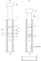
本実施形態に係る分離装置1は、親水部10と、分離用フィルタ20と、基材30と、吸引部50と、を備える。 The
吸引部50は、回収口32側に設けられ、回収口32側から基材30の内部の空気を吸引するためのものである。吸引部50は、回収口32に対して着脱自在である。吸引部50は、基材30の内面30aの親水部10に沿って、分離用フィルタ20から回収口32側に向けて移動可能なピストン等が用いられる。 The
次に、実施形態に係る分離装置1を用いて液体状の検体から血清又は血漿を分離する方法について説明する。図16は、実施形態における分離装置1の第12例を用いて液体状の検体から血清又は血漿を分離する方法を説明するための図である。 Next, a method for separating serum or plasma from a liquid specimen using the
ユーザは、被験者から血液を採取し、採取した血液を液体状の検体として、血液を容器59に入れておき、容器59内の血液に注入口31を接触させる。そして、分離用フィルタ20近傍に配置された吸引部50を、回収口32側に向けて図中矢印N方向に、基材30の内面30aの親水部10に沿ってスライドさせる。これにより、注入口31から基材30の内部に血液が注入される。そして、注入された血液は、分離用フィルタ20の第1主面21に到達する。到達した血液は、図16に示す矢印M方向に向けて分離用フィルタ20内を毛細管現象に基づいて分離用フィルタ20の第2主面22に向けて流れていくこととなる。血液は、分離用フィルタ20を流れることにより、血漿又は血清が分離される。 The user collects blood from a subject, uses the collected blood as a liquid sample, puts the blood in a
そして、親水部10は、親水性材料で構成される。これにより、親水部10に到達した血清又は血漿は、親水部10に吸収されることなく、第2主面22から親水部10上に流れることとなる。このため、血清又は血漿を液体の状態で取り出すことが可能となる。 The
本実施形態によれば、回収口32側から基材30の内部の空気を吸引するための吸引部50を更に備える。これにより、分離用フィルタ20を流れる血液の毛細管現象が促進され、血液から血清又は血漿をより早く分離させることができる。このため、血清又は血漿をより効率良く取り出すことが可能となる。 According to this embodiment, a
図17は、実施形態における分離装置1の第13例を示す図である。 FIG. 17 is a diagram showing a thirteenth example of the
本実施形態に係る分離装置1は、親水部10と、分離用フィルタ20と、基材30と、送気部60と、を備える。 The
送気部60は、注入口31側に設けられ、注入口31側から基材30の内部の空気を送るためのものである。送気部60は、注入口31に対して着脱自在である。送気部60は、基材30の内面30aの親水部10に沿って、注入口31側から分離用フィルタ20に向けて移動可能なピストン等が用いられる。 The
また、注入口31から分離用フィルタ20までの間の基材30の内部の空間には、透過フィルタ61が設けられる。透過フィルタ61は、液体状の検体及び空気等の気体が透過可能なものであり、例えば、ポリプロピレンを主な構成とするフィルム、ポリエチレンを主な構成とするフィルム、ポリオレフィンを主な構成とするフィルム、多孔質フィルム、PTFEメンブレンフィルム、日東電工株式会社製の超高分子量ポリエチレン多孔質フィルム、日東電工株式会社製のサンマップ(登録商標)、日東電工株式会社製の通気性シート ブレスロン(登録商標)、日東電工株式会社製の通気性粘着テープ ニトスルー(登録商標)、三菱ケミカル株式会社製の透湿性フィルムKTF、三菱ケミカル株式会社製の透湿通気防水フィルムエクセポール(登録商標)、スリーエムジャパン株式会社製の「マイクロポーラスフィルム」、株式会社トクヤマ製の微多孔質フィルム「NFシート」、帝人株式会社製のミライム等が用いられる。 Further, a
次に、実施形態に係る分離装置1を用いて液体状の検体から血清又は血漿を分離する方法について説明する。図18は、実施形態における分離装置1の第13例を用いて液体状の検体から血清又は血漿を分離する方法を説明するための図であって、図18(a)は、液体状の検体を注入口31に注入した状態を示す図であり、図18(b)は、液体状の検体から血清又は血漿を分離した状態を示す図である。 Next, a method for separating serum or plasma from a liquid specimen using the
ユーザは、被験者から血液を採取し、採取した血液を液体状の検体として、注入口31から血液を注入する。そして、注入された血液は、分離用フィルタ20の第1主面21に所定量滴下される。そして、ユーザは、注入口31側に送気部60を配置する。ユーザは、配置された送気部60を、分離用フィルタ20側に向けて基材30の内面30aに沿ってスライドさせる。これにより、血液は、図18(b)に示す矢印M方向に向けて、分離用フィルタ20内を毛細管現象に基づいて第2主面22に向けて流れていくこととなる。血液は、分離用フィルタ20を流れることにより、血漿又は血清が分離される。 A user collects blood from a subject, uses the collected blood as a liquid sample, and injects the blood from the
そして、親水部10は、親水性材料で構成される。これにより、親水部10に到達した血清又は血漿は、親水部10に吸収されることなく、第2主面22から親水部10上に流れることとなる。このため、血清又は血漿を液体の状態で取り出すことが可能となる。 The
その後、予め回収口32の下方側に用意した保管容器8に、液体の状態で取り出された血清又は血漿を収集する。 Thereafter, the serum or plasma taken out in a liquid state is collected into a
本実施形態によれば、注入口31側から基材30の内部に空気を送る送気部60を更に備える。これにより、分離用フィルタ20を流れる血液の毛細管現象が促進され、血液から血清又は血漿をより早く分離させることができる。このため、血清又は血漿をより効率良く取り出すことが可能となる。 According to this embodiment, the
本実施形態によれば、注入口31から分離用フィルタ20までの間の基材30の内部の空間に、透過フィルタ61が設けられる。これにより、送気部60により基材30の内部に送られる空気のチリや埃等の不要物を除去することができ、分離用フィルタ20に送られる空気を清浄することができる。このため、血液に不要物が混ざるのを防止することができ、血清又は血漿をより効率よく取り出すことが可能となる。 According to this embodiment, the
(検出装置100の実施形態)
図19を参照して、実施形態における検出装置100の第1例について説明する。図19は、実施形態における検出装置100の第1例を示す図である。(Embodiment of detection device 100)
A first example of the
検出装置100は、生体物質を検出するためのものである。検出装置100は、分離装置1と、検出部110とを備える。分離装置1は、親水部10と、分離用フィルタ20と、を備える。 The
親水部10は、板状に形成される。親水部10は、親水性材料で構成される。親水部10は、親水性フィルムからなる。親水部10は、分離用フィルタ20が設けられる第1主面11と、第1主面11とは反対側の第2主面12と、第1主面11と第2主面12とを繋ぐ端面13と、を有する。 The
分離用フィルタ20は、中空糸又は多孔質材の何れかで構成される。分離用フィルタ20は、親水部10の一部の領域に設けられる。 The
分離用フィルタ20は、第1主面21に、吸収材25を有する。吸収材25は、ポリウレタン等の合成樹脂が発泡成形されるスポンジ等が用いられる。分離用フィルタ20は、第2主面22が親水部10の一部の領域に設置される。 The
検出部110は、分離装置1から分離した血清又は血漿から生体物質を検出する。生体物質は、例えば、グルコースである。生体物質は、抗原又は抗体であってもよい。生体物質は、DNAであってもよい。生体物質は、RNAであってもよい。生体物質は、亜硫酸や亜硫酸塩等の無機物であってもよい。生体物質は、エクソソームであってもよい。生体物質は、有機物であってもよい。 The
検出部110は、浸透層120と、反射防止層130と、反応層140と、透明層150と、を備える。 The
浸透層120は、分離した血清又は血漿を浸透させるためのものである。浸透層120は、ポリエステル等の化学繊維、綿、ナノセルロース、ニトロセルロース、金属細線、プラスチックフィルタ、疎水物質、親水物質、ゼオライト等の多孔質物質で構成される。 The
浸透層120は、分離用フィルタ20から離間して親水部10に設けられる。浸透層120は、親水部10の第1主面11に設けられる。 The
反射防止層130は、反応層140のみの色を検出する際に、反射防止層130の両側に設けられる透明層150や浸透層120の色が、反応層140の色と重色や混色するのを防ぎ、検出時に誤った色を検出しないようにするためのものである。反射防止層130は、例えば、酸化チタン、金ナノ粒子、無機粒子、ゼオライト等の多孔質物質で構成される。 The
反射防止層130は、浸透層120を挟んで親水部10の反対側に設けられる。反射防止層130は、浸透層120の上側に積層される。なお、反射防止層130は、省略されてもよい。 The
反応層140は、分離した血清又は血漿と発色反応させるためのものである。反応層140は、浸透層120を挟んで親水部10とは反対側に設けられる。反応層140は、親水部10の第1主面11側に配置される。反応層140は、反射防止層130の上側に積層される。反応層140は、反射防止層130を挟んで浸透層120の反対側に設けられる。 The
反応層140は、例えば、ニトロセルロース、ポリエステル等の化学繊維、綿、ナノセルロース、金属細線、プラスチックフィルタ等で構成される。 The
反応層140は、分離した血清又は血漿と発色反応させるために、抗体、酵素、緩衝液、試薬、DNA、RNA、蛍光物質、Rnace、Dnace、ウィルス、微小金属、触媒、ゼオライト等の多孔質物質、コラーゲン、ペプチド、シュクロース、トレハロース、マルトース等が1以上含まれる。 The
例えば、検出する生体物質がグルコースの場合、反応層140において酵素法による発色反応が生じさせてもよい。反応層140は、グルコースオキシダーゼ等の酵素と、ペルオキシダーゼとが含まれる。これにより、分離装置1により分離された血清又は血漿が、反応層140に含まれるグルコースオキシダーゼと、反応し過酸化水素が発生する。発生した過酸化水素は、反応層140に含まれるペルオキシダーゼと反応し、反応層140が青紫色に発色する。 For example, if the biological substance to be detected is glucose, a coloring reaction may be caused in the
例えば、検出する生体物質が第1の抗原又は抗体の場合、反応層140において、抗体法、サンドイッチ法等の競合法による発色反応を生じさせてもよい。反応層140は、生体物質に含まれる第1の抗原又は抗体と結合する第2の抗原又は抗体が含まれる。これにより、分離装置1により分離された血清又は血漿に含まれる第1の抗原又は抗体が、反応層140に含まれる第2の抗原又は抗体と結合する。その後、標識された抗原又は抗体が含まれている2次抗体溶液を滴下した後、2次抗体溶液に含まれている標識剤を発光させる。発光溶液を滴下すると、反応層が発色する。 For example, when the biological substance to be detected is the first antigen or antibody, a coloring reaction may be caused in the
例えば、検出する生体物質がDNAの場合、反応層140においては、ポリメラーゼチェーン反応(PCR法)による発色反応を生じさせてもよい。反応層140は、試薬が含まれる。この試薬は、例えば、PCR用耐熱性酵素、反応緩衝剤、反応基質 (dNTPs)、PCRプライマー (オリゴヌクレオチド)、蛍光インターカレーター等が含まれる。分離した血清又は血漿に検出したい特定のDNAの配列が含まれる場合、ペルチェ素子等の所定の手段により反応層140を加温することにより、反応層140においてポリメラーゼチェーン反応が発生し、反応層140が蛍光発色する。その発色量を測定することにより、DNAの量を測定することもできる。 For example, when the biological substance to be detected is DNA, a coloring reaction may be caused in the
例えば、検出する生体物質がRNAの場合、反応層140においては、ポリメラーゼチェーン反応(PCR法)による発色反応を生じさせてもよい。反応層140は、逆転写酵素、プライマー等の増幅用試薬が含まれる。分離した血清又は血漿に検出したい特定のRNAの配列が含まれる場合、反応層140に含まれる逆転写酵素により、RNAからcDNAに変換される。その後、ペルチェ素子等の所定の手段により反応層140を加温することにより、増幅用試薬により遺伝子を増幅させ、反応層140においてポリメラーゼチェーン反応が発生し、反応層140が蛍光発色する。その発色量を測定することにより、RNAの量を測定することもできる。 For example, when the biological substance to be detected is RNA, a coloring reaction may be caused in the
例えば、検出する生体物質がDNAの場合、反応層140においては、DETECTR、SHERLOCK法、SHERLOCKv2による発色反応を生じさせてもよい。反応層140は、、CaS酵素、緩衝剤等が含まれる試薬が含まれる。分離した血清又は血漿に検出したい特定のDNAの配列が含まれる場合、ペルチェ素子等の所定の手段により反応層140を加温することにより、反応層140においてポリメラーゼチェーン反応が発生する。その後、特定のDNA配列がある場合、CRISPR酵素が作用し、塩基切断が発生する。塩基切断により、両端に発光物質を有する特定の塩基配列の物質も切断されることにより、反応層140が発光する。その発光量を測定することにより、DNAの量を測定することもできる。 For example, when the biological substance to be detected is DNA, the
例えば、検出する生体物質がRNAの場合、反応層140においては、SHERLOCK法、SHERLOCKv2による発色反応を生じさせてもよい。反応層140は、逆転写酵素、プライマー等の増幅用試薬、CRISPR酵素、ガイドRNAが含まれる。分離した血清又は血漿に検出したい特定のRNAの配列が含まれる場合、反応層140に含まれる逆転写酵素により、RNAからcDNAに変換される。その後、ペルチェ素子等の所定の手段により反応層140を加温することにより、増幅用試薬により遺伝子を増幅させ、反応層140においてポリメラーゼチェーン反応が発生する。その後、特定のRNA配列がある場合、CRISPR酵素が作用し、塩基切断が発生する。塩基切断により、両端に発光物質を有する特定の塩基配列の物質も切断されることにより、反応層140が発光する。その発光量を測定することにより、DNAの量を測定することもできる。 For example, when the biological substance to be detected is RNA, the
例えば、検出する生体物質が亜硫酸や亜硫酸塩の場合、反応層140においてはヨウ素デンプン反応による発色反応を生じさせてもよい。反応層140は、ヨウ素酸カリウム(KIO3)とでんぷんが含まれる。分離した血清又は血漿に検出したい亜硫酸や亜硫酸塩が含まれる場合、反応層140におけるヨウ素酸カリウムとでんぷんにより、反応層140が青紫色に発色する。For example, if the biological substance to be detected is sulfite or sulfite, a coloring reaction may be caused in the
透明層150は、透明性フィルムで構成され、例えば、PET(Polyethyleneterephthalate)が用いられる。透明層150は、ポリカーボネート、ガラス、SU-8、透明レジスト、ポリ塩化ビニリデンフィルム等のフィルム材、ポリイミドフィルム、ゼオライト等の多孔質物質が用いられてもよい。透明層150は、反応層140を挟んで浸透層120の反対側に設けられる。透明層150は、反応層140の上側に積層される。なお、透明層150は、省略されてもよい。 The
次に、検出装置100を用いて液体状の検体から生体物質を検出するための検出方法について説明する。 Next, a detection method for detecting biological substances from a liquid sample using the
まずユーザは、被験者から血液を採取し、採取した血液を液体状の検体として、吸収材25に所定量滴下する。この滴下された血液は、吸収材25に吸収される。吸収材25により吸収しきれなくなった血液は、分離用フィルタ20内を毛細管現象に基づいて分離用フィルタ20の第2主面22や端面23に向けて流れていくこととなる。血液は、分離用フィルタ20を流れることにより、血漿又は血清が分離される。 First, a user collects blood from a subject, and drops a predetermined amount of the collected blood as a liquid specimen onto the
そして、親水部10は、親水性材料で構成される。これにより、親水部10に到達した血清又は血漿は、親水部10に吸収されることなく、端面23から親水部10上に流れることとなる。 The
親水部10上を流れる血清又は血漿は、親水部10上に設けられた浸透層120に到達し、浸透層120内に浸透される。浸透層120を有することにより、血清又は血漿は、浸透層120内を均一に浸透することができる。 Serum or plasma flowing on the
浸透層120に浸透した血清又は血漿は、更に反射防止層130内に浸透する。反射防止層130に浸透した血清又は血漿は、反応層140に到達する。反応層140に到達した血清又は血漿は、反応層140と発色反応することとなる。これにより、検出部110は、血清又は血漿から発色反応を示した生体物質を検出することができる。ユーザは、血清又は血漿と発色反応した反応層140を目視や光学装置により確認することができる。 The serum or plasma that has permeated the
本実施形態によれば、生体物質を検出するための検出装置100であって、生体又は土壌から採取される採取物を含む液体状の検体から血清又は血漿を分離するための分離装置1と、分離装置1から分離した血清又は血漿から生体物質を検出する検出部110とを備え、分離装置1は、親水性材料で構成される親水部10と、親水部10の一部の領域に設けられるとともに、中空糸又は多孔質材料で構成される分離用フィルタ20と、を有し、検出部110は、親水部10に設けられる、分離した血清又は血漿を浸透させるための浸透層120と、浸透層120を挟んで親水部10とは反対側に設けられる、分離した血清又は血漿と発色反応させるための反応層140と、を有する。 According to the present embodiment, a
これにより、ユーザは、液体状の検体から分離した血清又は血漿から生体物質を確認することができる。このため、目的とする生体物質をより簡便に検出することができる。 This allows the user to identify biological substances from serum or plasma separated from a liquid specimen. Therefore, the target biological substance can be detected more easily.
また、本実施形態によれば、反応層140は、親水部10の第1主面11側に配置される。すなわち、分離用フィルタ20と反応層140とがともに親水部10の第1主面11側に配置されることとなる。これにより、液体状の検体を滴下する面と、反応層140の発色面とが同一の方向になる。このため、ユーザが反応層140を目視する方向や反応層140を確認するための光学装置の方向を、液体状の検体が滴下される方向と、同一にすることができる。その結果、反応層140の目視や光学装置での確認を行いやすくすることができる。 Further, according to the present embodiment, the
加えて、液体状の検体が親水部10の第1主面11から漏れてしまうのを抑制することができる。 In addition, leakage of the liquid specimen from the first
また、本実施形態によれば、検出部110は、反応層140を挟んで浸透層120の反対側に設けられる、透明性フィルムで構成される透明層150を有する。これにより、透明層150を通して、反応層140における発色反応を確認することができることに加え、血清又は血漿や発色反応した物質等が、反応層140から蒸発してしまうのを防止することができる。このため、生体物質の検出をより高精度に行うことが可能となる。 Further, according to the present embodiment, the
また、本実施形態によれば、反射防止層130を有する。これにより、反応層140の色と重色や混色するのを防ぎ、検出時に誤った色が検出されるのを抑制することができる。 Further, according to this embodiment, an
また、本実施形態によれば、液体状の検体を吸収するための吸収材25を有する。これにより、吸収材25が吸収できる上限が予め定められていることから、液体状の検体の量を定量化することができる。このため、一定量の液体状の検体から、血清又は血漿を分離することができる。 Further, according to this embodiment, an
図20は、実施形態における検出装置100の第2例を示す図である。検出装置100は、分離装置1と、検出部110とを備える。分離装置1は、親水部10と、分離用フィルタ20と、を備える。検出部110は、浸透層120と、反射防止層130と、反応層140と、透明層150と、を備える。 FIG. 20 is a diagram showing a second example of the
浸透層120は、分離用フィルタ20から離間して親水部10に設けられる。浸透層120は、親水部10の端面13に設けられる。 The
反射防止層130は、親水部10の第2主面12側に設けられる。反射防止層130は、浸透層120の下側に積層される。なお、反射防止層130は、省略されてもよい。 The
反応層140は、親水部10の第2主面12側に配置される。反応層140は、反射防止層130の下側に積層される。反応層140は、反射防止層130を挟んで浸透層120の反対側に設けられる。 The
透明層150は、反応層140を挟んで浸透層120の反対側に設けられる。透明層150は、反応層140の下側に積層される。透明層150は、反応層140を挟んで反射防止層130の反対側に設けられる。なお、透明層150は、省略されてもよい。 The
次に、検出装置100を用いて液体状の検体から生体物質を検出するための検出方法について説明する。 Next, a detection method for detecting biological substances from a liquid sample using the
まずユーザは、被験者から血液を採取し、採取した血液を液体状の検体として、吸収材25に所定量滴下する。この滴下された血液は、吸収材25に吸収される。吸収材25により吸収しきれなくなった血液は、分離用フィルタ20内を毛細管現象に基づいて分離用フィルタ20の第2主面22や端面23に向けて流れていくこととなる。血液は、分離用フィルタ20を流れることにより、血漿又は血清が分離される。 First, a user collects blood from a subject, and drops a predetermined amount of the collected blood as a liquid specimen onto the
そして、親水部10は、親水性材料で構成される。これにより、親水部10に到達した血清又は血漿は、親水部10に吸収されることなく、端面23から親水部10上に流れることとなる。 The
親水部10上を流れる血清又は血漿は、親水部10の端面13に設けられた浸透層120に到達し、浸透層120内に浸透される。 Serum or plasma flowing on the
浸透層120に浸透した血清又は血漿は、更に反射防止層130内に浸透する。反射防止層130に浸透した血清又は血漿は、反応層140に到達する。反応層140に到達した血清又は血漿は、反応層140と発色反応することとなる。これにより、検出部110は、血清又は血漿から発色反応を示した生体物質を検出することができる。ユーザは、血清又は血漿と発色反応した反応層140を目視や光学装置により確認することができる。 The serum or plasma that has permeated the
本実施形態によれば、反応層140は、親水部10の第2主面12側に配置される。すなわち、分離用フィルタ20が親水部10の第1主面11側に配置され、反応層140が親水部10の第2主面12側に配置されることとなる。これにより、液体状の検体を滴下する面と、反応層140の発色面とが反対の方向になる。このため、ユーザが反応層140を目視する方向や反応層140を確認するための光学装置の方向を、液体状の検体が滴下される方向と、反対にすることができる。その結果、光学装置等の小型化を行うことができる。 According to this embodiment, the
(保存装置200の実施形態)
図21を参照して、実施形態における保存装置200の第1例について説明する。図21は、実施形態における保存装置200の第1例を示す図である。(Embodiment of storage device 200)
A first example of the
保存装置200は、血清又は血漿を保存するためのものである。保存装置200は、分離装置1と、収容器210とを備える。分離装置1は、親水部10と、分離用フィルタ20と、基材30と、蓋部70と、を備える。
基材30は、外形が直方体状に形成され、内部に直方体状の空間が形成される。基材30は、例えば、プラスチック、金属等で構成される。基材30は、上壁391と、下壁392と、第1側壁393と、第2側壁394と、第3側壁と、第4側壁と、を有する(第3側壁と第4側壁の図示は省略する)。 The
上壁391と下壁392とは、互いに向かい合って配置される。第1側壁393、第2側壁394、第3側壁及び第4側壁は、上壁391と下壁392とを繋ぐ。第1側壁393と第2側壁394とは、互いに向かい合って配置される。また、第3側壁と第4側壁とは、互いに向かい合って配置される。 The
基材30は、開口された注入口31と、注入口31から離間して開口された回収口32とを有する。注入口31は、第1側壁393に設けられる。回収口32は、下壁392に設けられる。基材30は、注入口31に、吸収材25が嵌め込まれて設けられる。基材30は、回収口32に、ゴム等で構成される弁部36が設けられる。基材30は、吸収材25から離間して、内部に分離用フィルタ20が設けられる。 The
基材30は、第2側壁394の内面30aに親水部10が設けられる。なお、基材30は、内面30aの全てに親水部10が設けられてもよい。 In the
基材30は、内部に突出された鉤爪部34を有する。鉤爪部34は、注入口31に設けられる吸収材25と、分離用フィルタ20との間に配置される。鉤爪部34は、吸収材25よりも小さく形成される。また、鉤爪部34は、分離用フィルタ20よりも小さく形成される。 The
蓋部70は、注入口31を蓋するためのものである。蓋部70は、注入口31に対して着脱自在である。蓋部70は、第1側壁393をスライド可能に設けられてもよい。蓋部70は、注入口31に設けられた吸収材25を、基材30の内部に押し出すための押出機構71を有する。 The
親水部10は、板状に形成される。親水部10は、親水性材料で構成される。親水部10は、親水性フィルムからなる。 The
分離用フィルタ20は、中空糸又は多孔質材の何れかで構成される。分離用フィルタ20は、親水部10の一部の領域に設けられる。 The
分離用フィルタ20は、第1主面21から離間して吸収材25が設けられる。吸収材25は、ポリウレタン等の合成樹脂が発泡成形されるスポンジ等が用いられる。第2主面22は、親水部10の一部の領域に設置される。 The
収容器210は、分離装置1を収容可能なものである。収容器210は、挿入部220と、保存液230と、温度センサ240と、温度制御部250と、バッテリー260とを有する。 The
挿入部220は、基材30の回収口32に挿入可能なものである。挿入部220は、例えば、針状に形成される。 The
保存液230は、分離した血清又は血漿を保存するためのものである。保存液230は、例えば、EDTA等が用いられる。 The
温度センサ240は、収容器210の内部の温度を検知するものである。温度センサ240は、既知の温度センサを用いればよい。 The
温度制御部250は、収容器210の内部の温度を制御するものである。温度制御部250は、温度センサ240により検知された収容器210の内部の温度に応じて、所定の温度になるように制御される。温度制御部250は、ペルチェ素子や電子回路で構成される。温度制御部250は、ペルチェ素子に電位を印加することにより、加温及び冷却することができる。 The
バッテリー260は、温度センサ240や温度制御部250に電力を供給するものである。 The
次に、保存装置200を用いて血清又は血漿を保存するための保存方法について説明する。図22は、実施形態における保存装置200の第1例の分離装置1を用いて液体状の検体から血清又は血漿を分離する方法を説明するための図である。図23は、実施形態における保存装置200の第1例を用いて血清又は血漿を保存するための保存方法を説明するための図である。 Next, a preservation method for preserving serum or plasma using the
図22に示すように、まず第2側壁394が下側になるように分離装置1を設置する。ユーザは、血液を被験者から採取し、採取した血液を液体状の検体として、吸収材25に所定量滴下する。このとき、吸収材25と分離用フィルタ20とは鉤爪部34により離間されている。そして、蓋部70を注入口31に設置し、押出機構71により吸収材25を基材30の内部に向けて押し出す。これにより、血液を吸収した吸収材25が基材30の内部に押し出され、吸収材25に吸収された血液が分離用フィルタ20に到達する。血液は、分離用フィルタ20内を毛細管現象に基づいて分離用フィルタ20の第2主面22や端面23に向けて流れていくこととなる。血液は、分離用フィルタ20を流れることにより、血漿又は血清が分離される。 As shown in FIG. 22, first, the
親水部10は、親水性材料で構成される。これにより、親水部10に到達した血清又は血漿は、親水部10に吸収されることなく、端面23から親水部10上に流れることとなる。親水部10上を流れる血清又は血漿は、基材30の内部に収集されることとなる。 The
その後、図23に示すように、分離装置1を収容器210に収容する。収容する際には、基材の回収口32を、収容器210の挿入部220に挿入する。これにより、回収口32に設けられた弁部36を挿入部220が突き破り、基材30の内部に収集された血清又は血漿が保存液230に混合されて、収容器210の内部の保存液230に保存されることとなる。 Thereafter, as shown in FIG. 23, the
収容器210の内部は、温度センサ240により検知された温度に応じて、温度制御部250により所定の温度に制御されることとなる。 The inside of the
本実施形態によれば、血清又は血漿を保存するための保存装置200であって、生体から採取される採取物を含む液体状の検体から血清又は血漿を分離するための分離装置1と、分離装置1を収容可能な収容器210とを備え、分離装置1は、親水性材料で構成される親水部10と、親水部10の一部の領域に設けられるとともに、中空糸又は多孔質材料で構成される分離用フィルタ20と、を有し、収容器210は、分離した血清又は血漿を保存するための保存液230が収容される。 According to the present embodiment, a
これにより、ユーザは、液体状の検体から分離した血清又は血漿を、そのまま保存液230に保存することができる。このように、分離した血清又は血漿をわざわざ回収して、回収した血清又は血漿を保存容器に移し替える必要がない。このため、血清又は血漿を容易に保存することができる。 This allows the user to store serum or plasma separated from a liquid specimen in the
また、保存装置200に保存した血清又は血漿は、小型であるため、郵送等により送ることができる。このため、液体状の検体を採取した採取機関と、血清又は血漿を分析する分析機関とが、地理的に遠い場合であっても、大型の保存容器を必要とせずに、衛生的に送ることができる。 Furthermore, since the serum or plasma stored in the
本実施形態によれば、回収口32は、弁部36が設けられ、収容器210は、基材30の回収口32に挿入可能な挿入部220を有する。これにより、回収口32に挿入部220を挿入して、初めて基材30の内部に収集された血清又は血漿が、保存液230内に保存される。これにより、分離した血清又は血漿が、外気に触れることなく、そのまま保存液230で保存液230に保存することができる。このため、血清又は血漿の劣化を防止することが可能となる。 According to this embodiment, the
本実施形態によれば、分離装置1は、注入口31を蓋するための蓋部70を有し、蓋部70は、注入口31に設けられた液体状の検体を吸収するための吸収材25を、基材30の内部に押し出すための押出機構71を有し、基材30は、吸収材25と分離用フィルタ20との間に、鉤爪部34を有する。これにより、押出機構71を押し出す前の状態において、吸収材25が分離用フィルタ20に接触するのを防止することができる。そして、押出機構71を押し出して吸収材25を分離用フィルタ20に接触させることで、吸収材25に吸収された血液が、分離用フィルタ20に到達するし、血清又は血漿の分離を開始することができる。このため、血清又は血漿の分離を開始する時期を、ユーザ側で制御することが可能となる。 According to this embodiment, the
また、本実施形態によれば、液体状の検体を吸収するための吸収材25を有する。これにより、吸収材25が吸収できる上限が予め定められていることから、液体状の検体の量を定量化することができる。このため、一定量の液体状の検体から、血清又は血漿を分離することができる。 Further, according to this embodiment, an
図24は、実施形態における保存装置200の第2例を示す図である。 FIG. 24 is a diagram showing a second example of the
保存装置200は、血清又は血漿を保存するためのものである。保存装置200は、分離装置1と、収容器210とを備える。分離装置1は、親水部10と、分離用フィルタ20と、基材30と、蓋部70と、を備える。
基材30は、上壁391に注入口31を有する。 The
かかる場合であっても、保存装置200の第1例と同様の作用効果を発揮させることが可能となる。 Even in such a case, it is possible to achieve the same effects as the first example of the
(センサ300の実施形態)
図25を参照して、実施形態におけるセンサ300の第1例について説明する。図25は、実施形態におけるセンサ300の第1例を示す図である。(Embodiment of sensor 300)
A first example of the
センサ300は、血清又は血漿を保存するためのものである。センサ300は、分離装置1と、測定部310とを備える。分離装置1は、親水部10と、分離用フィルタ20と、一対の基材30と、スペーサー80と、を備える。
基材30は、板状に形成される。基材30は、例えば、プラスチック、金属等で構成される。基材30は、外形が直方体状に形成される。 The
一対の基材30のうち、一方を第1基材30-1とし、他方を第2基材30-2とする。第1基材30-1の端部と第2基材30-2の端部との間に、検体を注入するための注入口31が形成される。第1基材30-1と第2基材30-2との間には、注入口31から離間してスペーサー80が設けられる。スペーサー80が設けられることによって、第1基材30-1と第2基材30-2との間には空間が形成される。第1基材30-1と第2基材30-2との間には、注入口31側に第1空間Pが形成され、分離用フィルタ20を挟んで第1空間Pの反対側に第2空間Qが形成される。 One of the pair of
第1基材30-1に直交する断面において、第1空間Pの断面積は、第2空間Qの断面積よりも大きくなる。 In a cross section perpendicular to the first base material 30-1, the cross-sectional area of the first space P is larger than the cross-sectional area of the second space Q.
第1基材30-1は、分離用フィルタ20を挟んで第1空間P側と第2空間Q側とに、親水部10が設けられる。第2基材30-2は、分離用フィルタ20を挟んで第1空間P側に、親水部10が設けられる。第1基材30-1における親水部10と第2基材30-2における親水部10とは、向かい合って配置され、互いに離間されて配置される。第1基材30-1における親水部10と第2基材30-2における親水部10との距離は、十分狭く、液体状の検体の毛細管現象が展開される程度の距離で構成される。 The first base material 30-1 is provided with
分離用フィルタ20は、親水部10の一部の領域に設けられる。分離用フィルタ20は、第1基材30-1における親水部10と第2基材30-2における親水部10との間に設けられる。 The
測定部310は、分離装置1により分離した血清又は血漿から生体物質を測定するものである。測定部310は、反応部320と、変換部330と、制御電極340と、温度制御部350を有する。 The
反応部320は、分離した血清又は血漿と化学反応させるためのものである。反応部320は、第1基材30-1と第2基材30-2の間に設けられる。反応部320は、分離用フィルタ20を挟んで注入口31とは反対側に設けられる。反応部320は、例えば、ニトロセルロース、ポリエステル等の化学繊維、綿、ナノセルロース、金属細線、プラスチックフィルタ等で構成される。反応部320は、抗体、酵素、緩衝液、試薬、DNA、RNA、蛍光物質、Rnace、Dnace、ウィルス、微小金属、触媒、ゼオライト等の多孔質物質、コラーゲン、ペプチド、シュクロース、トレハロース、マルトース等が1以上含まれる。反応部320は、分離した血清又は血漿と反応層140との間で生じる化学反応を発生させるものが用いられてもよい。 The
変換部330は、分離した血清又は血漿と反応部320との化学反応に基づいて発生する電子を信号に変換するものである。変換部330は、例えば、作用極、参照極、対極とで構成される。変換部330は、例えば、定電圧法、定電流法、サイクリックボルタンメトリー等により、分離した血清又は血漿と反応部320との化学反応により発生する電子を、電気信号に変換する。測定部310は、変換部330により電子を信号に変換することにより、生体物質の定量的な測定をすることができる。 The
変換部330は、分離した血清又は血漿と反応部320との化学反応に基づいて発生する光を信号に変換するものであってもよい。変換部330は、導波路で構成される。変換部330は、例えば、定電圧法、定電流法、サイクリックボルタンメトリー等により、分離した血清又は血漿と反応部320との化学反応に基づいて発生する光を、電気信号に変換する。測定部310は、変換部330により光を信号に変換することにより、生体物質の定量的な測定をすることができる。 The
変換部330は、第1基材30-1と第2基材30-2の間に設けられる。変換部330は、第1基材30-1とスペーサー80との間に固定される。変換部330は、第2基材30-2とスペーサー80との間に固定されてもよい。変換部330は、分離用フィルタ20を挟んで注入口31とは反対側に設けられる。 The converting
制御電極340は、温度制御部350に電流及び電圧を付与するものである。制御電極340は、1つ又は複数の電極で構成される。 The
制御電極340は、第1基材30-1と第2基材30-2の間に設けられる。制御電極340は、第2基材30-2とスペーサー80との間に固定される。なお、制御電極340は、第1基材30-1とスペーサー80との間に固定されてもよい。制御電極340は、分離用フィルタ20を挟んで注入口31とは反対側に設けられる。
制御電極340は、例えば、交流による電流を付与することにより、ローレンツ力により、反応部320に含まれる微粒子にブラウン運動を発生させ、血清又は血漿と反応部320との反応が促進させることができる。 For example, by applying an alternating current, the
温度制御部350は、第1基材30-1と第2基材30-2との間の空間の温度を制御するものである。温度制御部350は、第1基材30-1と第2基材30-2との間の空間の温度を、制御電極340により所定の温度になるように制御するものである。温度制御部350は、ペルチェ素子や電子回路で構成される。温度制御部350は、制御電極により電位を印加することにより、第1基材30-1と第2基材30-2との間の空間を、加温及び冷却することができる。 The
温度制御部350は、例えば、加温により、反応部320に含まれる微粒子にブラウン運動を発生させ、血清又は血漿と反応部320との反応が促進させることができる。 For example, the
温度制御部350は、第1基材30-1と第2基材30-2の間に設けられる。温度制御部350は、第2基材30-2に固定される。温度制御部350は、第1基材30-1に固定されてもよい。温度制御部350は、分離用フィルタ20を挟んで注入口31とは反対側に設けられる。 The
次に、センサ300を用いて生体物質を測定するための測定方法について説明する。 Next, a measurement method for measuring biological substances using the
ユーザは、被験者から血液を採取し、採取した血液を液体状の検体として、注入口31から血液を注入する。これにより、注入口31から注入された血液は、第1基材30-1と第2基材30-2との間を、毛細管現象に基づいて分離用フィルタ20に到達する。そして、血液は、分離用フィルタ20内を毛細管現象に基づいて第2空間Q側に向けて流れていくこととなる。血液は、分離用フィルタ20を流れることにより、血漿又は血清が分離される。 A user collects blood from a subject, uses the collected blood as a liquid sample, and injects the blood from the
そして、親水部10は、親水性材料で構成される。これにより、親水部10に到達した血清又は血漿は、親水部10に吸収されることなく、分離用フィルタ20から親水部10上に流れることとなる。このため、血清又は血漿を液体の状態で取り出すことが可能となる。 The
分離用フィルタ20により分離した血清又は血漿は、反応部320に到達する。反応部320に到達した血清又は血漿は、反応部320と化学反応することとなる。そして、化学反応により発生する電子又は光を変換部330により信号に変換することにより、測定部310は、血清又は血漿から化学反応を示した生体物質を測定することができる。 Serum or plasma separated by the
本実施形態によれば、生体物質を測定するためのセンサであって、生体から採取される採取物を含む液体状の検体から血清又は血漿を分離するための分離装置1と、分離装置1により分離した血清又は血漿から生体物質を測定する測定部310とを備え、前記分離装置1は、親水性材料で構成される親水部10と、親水部10の一部の領域に設けられるとともに、中空糸又は多孔質材料で構成される分離用フィルタ20と、を有し、測定部310は、分離した血清又は血漿と化学反応させるための反応部320と、血清又は血漿と前記試薬との化学反応に基づいて発生する電子を信号に変換する変換部330と、を有する。 According to the present embodiment, the sensor for measuring biological substances includes a
本実施形態によれば、生体物質を測定するためのセンサであって、生体から採取される採取物を含む液体状の検体から血清又は血漿を分離するための分離装置1と、分離装置1により分離した血清又は血漿から生体物質を測定する測定部310とを備え、前記分離装置1は、親水性材料で構成される親水部10と、親水部10の一部の領域に設けられるとともに、中空糸又は多孔質材料で構成される分離用フィルタ20と、を有し、測定部310は、分離した血清又は血漿と化学反応させるための反応部320と、血清又は血漿と前記試薬との化学反応に基づいて発生する光を信号に変換する変換部330と、を有する。 According to the present embodiment, the sensor for measuring biological substances includes a
これにより、ユーザは、液体状の検体から分離した血清又は血漿から生体物質を測定することができる。このため、目的とする生体物質をより簡便に測定することができる。 This allows the user to measure biological substances from serum or plasma separated from a liquid specimen. Therefore, the target biological substance can be measured more easily.
また、本実施形態によれば、第1基材30-1と第2基材30-2との間には、注入口31から離間してスペーサー80が設けられる。これにより、第1基材30-1と第2基材30-2との間の空間を保持することができる。このため、注入口31から注入された液体状の検体が、毛細管現象に基づいて分離用フィルタ20に到達することができる。 Further, according to the present embodiment, a
図26は、実施形態におけるセンサ300の第2例を示す平面図である。 FIG. 26 is a plan view showing a second example of the
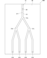
センサ300は、分離装置1と、測定部310と、を備える。分離装置1は、親水部10と、分離用フィルタ20と、基材30とを備える。 The
基材30は、板状に形成され、液体状の検体を注入するための注入口31と、注入口31から繋がる溝状の流路37を有する。流路37は、親水部10が設けられる。流路37は、分岐部37aから複数(図示では2つ)の流路37に分岐する。また、分岐部37aから分岐した2つの流路37は、更に分岐部37b及び分岐部37cからそれぞれ2つの流路37に分岐する。分岐部37b及び分岐部37cから分岐した4つの流路37の端部には、測定部310が設けられる。流路37は、注入口31と分岐部37aとの間に、分離用フィルタ20が設けられる。 The
次に、センサ300を用いて生体物質を測定するための測定方法について説明する。 Next, a measurement method for measuring biological substances using the
ユーザは、被験者から血液を採取し、採取した血液を液体状の検体として、注入口31から血液を注入する。これにより、注入口31から注入された血液は、流路37を介して分離用フィルタ20に到達する。そして、血液は、分離用フィルタ20内を毛細管現象に基づいて分岐部37a側に向けて流れていくこととなる。血液は、分離用フィルタ20を流れることにより、血漿又は血清が分離される。 A user collects blood from a subject, uses the collected blood as a liquid sample, and injects the blood from the
そして、親水部10は、親水性材料で構成される。これにより、親水部10に到達した血清又は血漿は、親水部10に吸収されることなく、分離用フィルタ20から親水部10上に流れることとなる。このため、血清又は血漿を液体の状態で取り出すことが可能となる。 The
分離用フィルタ20により分離した血清又は血漿は、分岐部37aから2つの流路37に分岐される。そして、分岐部37b及び分岐部37cに到達した血清又は血漿は、さらに4つの流路37に分岐され、4つの流路37の端部に設けられた各々の測定部310に到達する。これにより、各々の測定部310は、血清又は血漿から化学反応を示した生体物質を測定することができる。このように、生体物質の測定を、同時に複数行うことができる。各々の測定部310は、同一の生体物質を測定するものであってもよいし、異なる生体物質を測定するものであってもよい。 Serum or plasma separated by the
図27は、実施形態におけるセンサ300の第3例を示す平面図である。図28は、実施形態におけるセンサ300の第4例を示す平面図である。 FIG. 27 is a plan view showing a third example of the
センサ300は、分離装置1と、測定部310と、を備える。分離装置1は、親水部10と、分離用フィルタ20と、基材30とを備える。 The
基材30は、平面視円形状の板状に形成される。基材30は、平面視における略中央に液体状の検体を注入するための注入口31と、注入口31から放射状に延びる溝状の4つの流路37を有する。流路37は、親水部10が設けられる。各々の流路37の端部には、測定部310が設けられる。図27に示すように、分離用フィルタ20は、流路37上であって、注入口31と測定部310との間に設けられる。また、図28に示すように、分離用フィルタ20は、各々の流路37への分岐点である注入口31に、設けられてもよい。 The
次に、センサ300を用いて生体物質を測定するための測定方法について説明する。 Next, a measurement method for measuring biological substances using the
ユーザは、被験者から血液を採取し、採取した血液を液体状の検体として、注入口31から血液を注入する。これにより、注入口31から注入された血液は、分離用フィルタ20に到達する。そして、血液は、分離用フィルタ20内を毛細管現象に基づいて測定部310側に向けて流路37を流れていくこととなる。血液は、分離用フィルタ20を流れることにより、血漿又は血清が分離される。 A user collects blood from a subject, uses the collected blood as a liquid sample, and injects the blood from the
そして、親水部10は、親水性材料で構成される。これにより、親水部10に到達した血清又は血漿は、親水部10に吸収されることなく、分離用フィルタ20から親水部10上に流れることとなる。このため、血清又は血漿を液体の状態で取り出すことが可能となる。 The
分離用フィルタ20により分離した血清又は血漿は、4つの流路37の端部に設けられた測定部310に到達する。これにより、測定部310は、血清又は血漿から化学反応を示した生体物質を測定することができる。 The serum or plasma separated by the
以上、この発明の実施形態のいくつかを説明したが、これらの実施形態は例として提示したものであり、発明の範囲を限定することは意図していない。また、これらの実施形態は、適宜組み合わせて実施することが可能である。さらに、この発明は、上記いくつかの実施形態の他、様々な新規な形態で実施することができる。したがって、上記いくつかの実施形態のそれぞれは、この発明の要旨を逸脱しない範囲で、種々の省略、置き換え、変更が可能である。このような新規な形態や変形は、この発明の範囲や要旨に含まれるとともに、特許請求の範囲に記載された発明、及び特許請求の範囲に記載された発明の均等物の範囲に含まれる。 Although some embodiments of the present invention have been described above, these embodiments are presented as examples and are not intended to limit the scope of the invention. Moreover, these embodiments can be implemented in combination as appropriate. Furthermore, this invention can be implemented in various new forms in addition to the several embodiments described above. Therefore, various omissions, substitutions, and changes can be made to each of the several embodiments described above without departing from the gist of the present invention. Such novel forms and modifications are included within the scope and gist of the present invention, as well as within the scope of the claimed inventions and equivalents of the claimed inventions.
1 :分離装置
10 :親水部
11 :第1主面
12 :第2主面
13 :端面
14 :溝
14a :底面
14b :側面
15 :収集部
16 :嵌合部
16a :拡径部
16b :開口部
20 :分離用フィルタ
21 :第1主面
22 :第2主面
23 :端面
25 :吸収材
30 :基材
30a :内面
31 :注入口
32 :回収口
34 :鉤爪部
36 :弁部
37 :流路
391 :上壁
392 :下壁
393 :第1側壁
394 :第2側壁
40 :疎水部
50 :吸引部
51 :透過フィルタ
59 :容器
60 :送気部
61 :透過フィルタ
70 :蓋部
71 :押出機構
80 :スペーサー
90 :支持部材
91 :突起部
92 :挟持部
100 :検出装置
110 :検出部
120 :浸透層
130 :反射防止層
140 :反応層
150 :透明層
200 :保存装置
210 :収容器
220 :挿入部
230 :保存液
240 :温度センサ
250 :温度制御部
260 :バッテリー
300 :センサ
310 :測定部
320 :反応部
330 :変換部
340 :制御電極
350 :温度制御部
8 :保管容器
9 :回収装置
93 :先端部1 : Separation device 10 : Hydrophilic part 11 : First principal surface 12 : Second principal surface 13 : End surface 14 : Groove 14a : Bottom surface 14b : Side surface 15 : Collection part 16 : Fitting part 16a : Expanded diameter part 16b : Opening part 20: Separation filter 21: First main surface 22: Second main surface 23: End surface 25: Absorbent material 30: Base material 30a: Inner surface 31: Inlet port 32: Collection port 34: Claw portion 36: Valve portion 37: Flow Channel 391 : Upper wall 392 : Lower wall 393 : First side wall 394 : Second side wall 40 : Hydrophobic part 50 : Suction part 51 : Transmission filter 59 : Container 60 : Air supply part 61 : Transmission filter 70 : Lid part 71 : Extrusion Mechanism 80 : Spacer 90 : Support member 91 : Projection part 92 : Holding part 100 : Detection device 110 : Detection part 120 : Penetration layer 130 : Antireflection layer 140 : Reaction layer 150 : Transparent layer 200 : Preservation device 210 : Container 220 : Insertion part 230 : Preservation liquid 240 : Temperature sensor 250 : Temperature control part 260 : Battery 300 : Sensor 310 : Measurement part 320 : Reaction part 330 : Conversion part 340 : Control electrode 350 : Temperature control part 8 : Storage container 9 : Recovery Device 93: Tip
Claims (17)
親水性材料で構成される親水部と、
前記親水部の一部の領域に設けられるとともに、中空糸又は多孔質材料で構成される分離用フィルタと、
前記分離用フィルタを前記親水部に支持する支持部材と、を備え、
前記支持部材は、前記分離用フィルタに挿通する複数の突起部を有すること
を特徴とする分離装置。 A separation device for separating at least serum or plasma from a liquid sample including a sample collected from a living body or soil,
a hydrophilic part made of a hydrophilic material;
a separation filter provided in a part of the hydrophilic portion and made of a hollow fiber or a porous material;
a support member that supports the separation filter on the hydrophilic part,
The separation device characterized in that the support member has a plurality of protrusions that are inserted into the separation filter .
を特徴とする請求項1記載の分離装置。 The separation device according to claim 1, wherein the hydrophilic portion is formed in a plate shape and is formed to be inclined downward in a direction away from the separation filter.
を特徴とする請求項1記載の分離装置。 The separation device according to claim 1, wherein the hydrophilic portion is formed with a groove extending in a direction away from the separation filter.
を特徴とする請求項1記載の分離装置。 The separation device according to claim 1, wherein the hydrophilic portion is made of a hydrophilic film.
を特徴とする請求項1記載の分離装置。 The separation device according to claim 1, wherein the hydrophilic part has a collecting part for collecting separated serum or plasma.
を特徴とする請求項1記載の分離装置。 The separation device according to claim 1, wherein the hydrophilic portion has a fitting portion for fitting a recovery device for recovering separated serum or plasma.
前記基材は、一方側の端部に形成される注入口と、前記注入口とは反対側に形成される回収口と、を有し、
前記親水部は、前記基材の内面に設けられ、
前記分離用フィルタは、前記回収口から離間して前記基材の内部に配置されること
を特徴とする請求項1記載の分離装置。 further comprising a base material formed into a cylindrical shape,
The base material has an injection port formed at one end, and a recovery port formed on the opposite side to the injection port,
The hydrophilic portion is provided on the inner surface of the base material,
The separation device according to claim 1, wherein the separation filter is arranged inside the base material away from the recovery port.
を特徴とする請求項7記載の分離装置。 The separation device according to claim 7, further comprising a hydrophobic portion made of a hydrophobic material at an end of the inner surface of the base material on the side of the recovery port.
を特徴とする請求項7記載の分離装置。 The separation device according to claim 7, further comprising a suction section for sucking air inside the base material from the recovery port side.
を特徴とする請求項7記載の分離装置。 The separation device according to claim 7, further comprising an air supply unit that sends air from the injection port side to the inside of the base material.
前記注入口に設けられる蓋部と、を備え、A lid provided on the injection port,
前記基材は、前記注入口に嵌め込まれるとともに液体状の検体を吸収するための吸収材と、前記吸収材と前記分離用フィルタとの間に設けられる鉤爪部と、を有し、The base material includes an absorbent material that is fitted into the injection port and absorbs a liquid specimen, and a claw portion that is provided between the absorbent material and the separation filter,
前記蓋部は、前記吸収材を前記基材の内部に押し出すための押出機構を有することThe lid part has an extrusion mechanism for extruding the absorbent material into the inside of the base material.
を特徴とする請求項1記載の分離装置。The separation device according to claim 1, characterized in that:
生体又は土壌から採取される採取物を含む液体状の検体から血清又は血漿を分離するための分離装置と、前記分離装置から分離した血清又は血漿から生体物質を検出する検出部とを備え、
前記分離装置は、
親水性材料で構成される親水部と、
前記親水部の一部の領域に設けられるとともに、中空糸又は多孔質材料で構成される分離用フィルタと、
前記分離用フィルタを前記親水部に支持する支持部材と、を有し、
前記支持部材は、前記分離用フィルタに挿通する複数の突起部を有し、
前記検出部は、
前記親水部に設けられる、分離した血清又は血漿を浸透させるための浸透層と、
前記浸透層を挟んで前記親水部とは反対側に設けられる、分離した血清又は血漿と発色反応させるための反応層と、を有すること
を特徴とする検出装置。 A detection device for detecting biological substances,
A separation device for separating serum or plasma from a liquid specimen including a sample collected from a living body or soil, and a detection unit for detecting biological substances from the serum or plasma separated from the separation device,
The separation device includes:
a hydrophilic part made of a hydrophilic material;
a separation filter provided in a part of the hydrophilic portion and made of a hollow fiber or a porous material;
a support member that supports the separation filter on the hydrophilic part,
The support member has a plurality of protrusions that are inserted into the separation filter,
The detection unit includes:
a permeable layer provided in the hydrophilic part for permeating separated serum or plasma;
A detection device comprising: a reaction layer for causing a color reaction with separated serum or plasma, which is provided on the opposite side of the hydrophilic portion with the permeation layer in between.
を特徴とする請求項12記載の検出装置。 13. The detection device according to claim 12 , wherein the detection section includes a transparent layer formed of a transparent film and provided on the opposite side of the permeation layer with the reaction layer interposed therebetween.
前記反応層は、前記親水部の前記第1主面側に配置されること
を特徴とする請求項12記載の検出装置。 The hydrophilic portion has a first main surface on which the separation filter is provided, and a second main surface opposite to the first main surface,
The detection device according to claim 12 , wherein the reaction layer is arranged on the first main surface side of the hydrophilic portion.
前記反応層は、前記親水部の前記第2主面側に配置されること
を特徴とする請求項12記載の検出装置。 The hydrophilic portion has a first main surface on which the separation filter is provided, and a second main surface opposite to the first main surface,
The detection device according to claim 12 , wherein the reaction layer is arranged on the second main surface side of the hydrophilic portion.
生体又は土壌から採取される採取物を含む液体状の検体から血清又は血漿を分離するための分離装置と、前記分離装置を収容可能な収容器とを備え、
前記分離装置は、
親水性材料で構成される親水部と、
前記親水部の一部の領域に設けられるとともに、中空糸又は多孔質材料で構成される分離用フィルタと、
前記分離用フィルタを前記親水部に支持する支持部材と、を有し、
前記支持部材は、前記分離用フィルタに挿通する複数の突起部を有し、
前記収容器は、分離した血清又は血漿を保存するための保存液が収容されること
を特徴とする保存装置。 A storage device for storing serum or plasma, the storage device comprising:
A separation device for separating serum or plasma from a liquid sample including a sample collected from a living body or soil, and a container capable of accommodating the separation device,
The separation device includes:
a hydrophilic part made of a hydrophilic material;
a separation filter provided in a part of the hydrophilic portion and made of a hollow fiber or a porous material;
a support member that supports the separation filter on the hydrophilic part,
The support member has a plurality of protrusions that are inserted into the separation filter,
The storage device is characterized in that the storage container stores a storage solution for storing separated serum or plasma.
生体又は土壌から採取される採取物を含む液体状の検体から血清又は血漿を分離するための分離装置と、前記分離装置により分離した血清又は血漿から生体物質を測定する測定部とを備え、
前記分離装置は、
親水性材料で構成される親水部と、
前記親水部の一部の領域に設けられるとともに、中空糸又は多孔質材料で構成される分離用フィルタと、
前記分離用フィルタを前記親水部に支持する支持部材と、を有し、
前記支持部材は、前記分離用フィルタに挿通する複数の突起部を有し、
前記測定部は、分離した血清又は血漿と化学反応させるための反応部と、血清又は血漿と前記反応部との化学反応に基づいて発生する電子又は光を信号に変換する変換部と、有すること
を特徴とするセンサ。 A sensor for measuring biological substances,
comprising a separation device for separating serum or plasma from a liquid specimen including a sample collected from a living body or soil, and a measurement unit for measuring biological substances from the serum or plasma separated by the separation device,
The separation device includes:
a hydrophilic part made of a hydrophilic material;
a separation filter provided in a part of the hydrophilic portion and made of a hollow fiber or a porous material;
a support member that supports the separation filter on the hydrophilic part,
The support member has a plurality of protrusions that are inserted into the separation filter,
The measuring section may include a reaction section for causing a chemical reaction with the separated serum or plasma, and a conversion section for converting electrons or light generated based on the chemical reaction between the serum or plasma and the reaction section into a signal. A sensor featuring:
Applications Claiming Priority (1)
| Application Number | Priority Date | Filing Date | Title |
|---|---|---|---|
| PCT/JP2020/007516 WO2021171378A1 (en) | 2020-02-25 | 2020-02-25 | Separation device, detection device, preservation device, and sensor |
Publications (3)
| Publication Number | Publication Date |
|---|---|
| JPWO2021171378A1 JPWO2021171378A1 (en) | 2021-09-02 |
| JPWO2021171378A5 JPWO2021171378A5 (en) | 2023-02-03 |
| JP7399514B2 true JP7399514B2 (en) | 2023-12-18 |
Family
ID=77489985
Family Applications (1)
| Application Number | Title | Priority Date | Filing Date |
|---|---|---|---|
| JP2022502621A Active JP7399514B2 (en) | 2020-02-25 | 2020-02-25 | Separation equipment, detection equipment, storage equipment and sensors |
Country Status (2)
| Country | Link |
|---|---|
| JP (1) | JP7399514B2 (en) |
| WO (1) | WO2021171378A1 (en) |
Citations (7)
| Publication number | Priority date | Publication date | Assignee | Title |
|---|---|---|---|---|
| US5916521A (en) | 1995-01-04 | 1999-06-29 | Spectral Diagnostics, Inc. | Lateral flow filter devices for separation of body fluids from particulate materials |
| JP2000502451A (en) | 1995-12-22 | 2000-02-29 | ユニバーサル ヘルスウォッチ,インコーポレーテッド | Diagnostic analysis leading to plasma separation |
| JP2003135435A (en) | 2001-08-22 | 2003-05-13 | Kyowa Medex Co Ltd | Blood specimen collecting implement, method of preparing solution for quantification using the same, appliance for preparing solution for quantification and method of using the same and quantification method using solution for quantification |
| JP2003194806A (en) | 2001-12-27 | 2003-07-09 | Minolta Co Ltd | Chip for separation of blood cell |
| JP2003254934A (en) | 2002-03-01 | 2003-09-10 | Matsushita Electric Ind Co Ltd | Biosensor |
| JP2011133235A (en) | 2009-12-22 | 2011-07-07 | Physical Screening Inc | Storage device for liquid to be tested |
| JP2012529039A (en) | 2009-06-04 | 2012-11-15 | インフォピア カンパニー,リミテッド | Strip for biometric data measurement and biometric data measurement method |
Family Cites Families (4)
| Publication number | Priority date | Publication date | Assignee | Title |
|---|---|---|---|---|
| ES2070942T3 (en) * | 1989-04-07 | 1995-06-16 | Abbott Lab | METHOD AND DEVICE FOR THE SEPARATION OF PLASMA OR WHOLE BLOOD SERUM. |
| JP3186106B2 (en) * | 1991-07-30 | 2001-07-11 | テルモ株式会社 | Blood component separation storage device |
| JP6286674B2 (en) * | 2012-10-22 | 2018-03-07 | パナソニックIpマネジメント株式会社 | Filter device |
| JP6539935B2 (en) * | 2017-10-12 | 2019-07-10 | Blue Industries株式会社 | Separation filter, pretreatment kit for gene analysis |
-
2020
- 2020-02-25 JP JP2022502621A patent/JP7399514B2/en active Active
- 2020-02-25 WO PCT/JP2020/007516 patent/WO2021171378A1/en active Application Filing
Patent Citations (7)
| Publication number | Priority date | Publication date | Assignee | Title |
|---|---|---|---|---|
| US5916521A (en) | 1995-01-04 | 1999-06-29 | Spectral Diagnostics, Inc. | Lateral flow filter devices for separation of body fluids from particulate materials |
| JP2000502451A (en) | 1995-12-22 | 2000-02-29 | ユニバーサル ヘルスウォッチ,インコーポレーテッド | Diagnostic analysis leading to plasma separation |
| JP2003135435A (en) | 2001-08-22 | 2003-05-13 | Kyowa Medex Co Ltd | Blood specimen collecting implement, method of preparing solution for quantification using the same, appliance for preparing solution for quantification and method of using the same and quantification method using solution for quantification |
| JP2003194806A (en) | 2001-12-27 | 2003-07-09 | Minolta Co Ltd | Chip for separation of blood cell |
| JP2003254934A (en) | 2002-03-01 | 2003-09-10 | Matsushita Electric Ind Co Ltd | Biosensor |
| JP2012529039A (en) | 2009-06-04 | 2012-11-15 | インフォピア カンパニー,リミテッド | Strip for biometric data measurement and biometric data measurement method |
| JP2011133235A (en) | 2009-12-22 | 2011-07-07 | Physical Screening Inc | Storage device for liquid to be tested |
Also Published As
| Publication number | Publication date |
|---|---|
| JPWO2021171378A1 (en) | 2021-09-02 |
| WO2021171378A1 (en) | 2021-09-02 |
Similar Documents
| Publication | Publication Date | Title |
|---|---|---|
| JP4513085B2 (en) | Sample container | |
| EP1387170B1 (en) | Specimen analyzing implement | |
| JP4627395B2 (en) | Analytical cartridge and liquid feeding control device | |
| JP2020024220A (en) | Processing and control for fluid | |
| JP3325018B2 (en) | Analytical test element having a narrowed capillary channel | |
| US10463290B2 (en) | Biological sample collection and storage assembly | |
| RO119751B1 (en) | Optical disk, apparatus for conducting an optical control, method for detecting the presence or the absence of an analyte in a sample and method for controlling a biological, chemical or biochemical sample | |
| US10350592B2 (en) | Sample collection and transfer device | |
| JP2009543547A (en) | Disposable device for analyzing nucleic acid-containing liquid sample using nucleic acid amplification device | |
| JP2012523571A (en) | Microfluidic clinical analyzer | |
| WO2003064046A1 (en) | Sample collection and testing system | |
| US20060016747A1 (en) | Glass-fiber filter for blood filtration, blood filtration device and blood analysis element | |
| US10675622B2 (en) | Sample collection and transfer device | |
| EP3495824A1 (en) | Analysis cell, analysis device, analysis equipment, and analysis system | |
| JP5444632B2 (en) | Nucleic acid amplification method and container used therefor | |
| JPH10132800A (en) | Specimen-protecting container integral with humor-separating sheet | |
| JP7399514B2 (en) | Separation equipment, detection equipment, storage equipment and sensors | |
| US20090260458A1 (en) | High throughput dispenser | |
| CN111644216B (en) | Microfluidic structures for plasma separation and detection | |
| US20220276238A1 (en) | Poc test system and method | |
| KR20150101316A (en) | Fluid analysis cartridge | |
| JP5953128B2 (en) | Method for producing capillary array for assay | |
| US11857966B1 (en) | Methods and devices for sample collection and sample separation | |
| CN114018835A (en) | Micro whole blood pretreatment and automatic quantitative plasma distribution device and analysis method | |
| WO1998010283A1 (en) | Sample protective container integral with body fluid separating sheet |
Legal Events
| Date | Code | Title | Description |
|---|---|---|---|
| A521 | Request for written amendment filed |
Free format text: JAPANESE INTERMEDIATE CODE: A523 Effective date: 20230125 |
|
| A621 | Written request for application examination |
Free format text: JAPANESE INTERMEDIATE CODE: A621 Effective date: 20230125 |
|
| TRDD | Decision of grant or rejection written | ||
| A01 | Written decision to grant a patent or to grant a registration (utility model) |
Free format text: JAPANESE INTERMEDIATE CODE: A01 Effective date: 20231128 |
|
| A61 | First payment of annual fees (during grant procedure) |
Free format text: JAPANESE INTERMEDIATE CODE: A61 Effective date: 20231129 |
|
| R150 | Certificate of patent or registration of utility model |
Ref document number: 7399514 Country of ref document: JP Free format text: JAPANESE INTERMEDIATE CODE: R150 |
|
| R250 | Receipt of annual fees |
Free format text: JAPANESE INTERMEDIATE CODE: R250 |