WO2021166718A1 - 車載用の計測装置ユニットおよび車載用の計測装置ユニットにおける統合データ生成方法 - Google Patents
車載用の計測装置ユニットおよび車載用の計測装置ユニットにおける統合データ生成方法 Download PDFInfo
- Publication number
- WO2021166718A1 WO2021166718A1 PCT/JP2021/004614 JP2021004614W WO2021166718A1 WO 2021166718 A1 WO2021166718 A1 WO 2021166718A1 JP 2021004614 W JP2021004614 W JP 2021004614W WO 2021166718 A1 WO2021166718 A1 WO 2021166718A1
- Authority
- WO
- WIPO (PCT)
- Prior art keywords
- detection area
- data
- detector
- detection
- detectors
- Prior art date
- Legal status (The legal status is an assumption and is not a legal conclusion. Google has not performed a legal analysis and makes no representation as to the accuracy of the status listed.)
- Ceased
Links
Images


Classifications
-
- G—PHYSICS
- G01—MEASURING; TESTING
- G01S—RADIO DIRECTION-FINDING; RADIO NAVIGATION; DETERMINING DISTANCE OR VELOCITY BY USE OF RADIO WAVES; LOCATING OR PRESENCE-DETECTING BY USE OF THE REFLECTION OR RERADIATION OF RADIO WAVES; ANALOGOUS ARRANGEMENTS USING OTHER WAVES
- G01S17/00—Systems using the reflection or reradiation of electromagnetic waves other than radio waves, e.g. lidar systems
- G01S17/87—Combinations of systems using electromagnetic waves other than radio waves
-
- G—PHYSICS
- G01—MEASURING; TESTING
- G01S—RADIO DIRECTION-FINDING; RADIO NAVIGATION; DETERMINING DISTANCE OR VELOCITY BY USE OF RADIO WAVES; LOCATING OR PRESENCE-DETECTING BY USE OF THE REFLECTION OR RERADIATION OF RADIO WAVES; ANALOGOUS ARRANGEMENTS USING OTHER WAVES
- G01S13/00—Systems using the reflection or reradiation of radio waves, e.g. radar systems; Analogous systems using reflection or reradiation of waves whose nature or wavelength is irrelevant or unspecified
- G01S13/86—Combinations of radar systems with non-radar systems, e.g. sonar, direction finder
- G01S13/865—Combination of radar systems with lidar systems
-
- G—PHYSICS
- G01—MEASURING; TESTING
- G01S—RADIO DIRECTION-FINDING; RADIO NAVIGATION; DETERMINING DISTANCE OR VELOCITY BY USE OF RADIO WAVES; LOCATING OR PRESENCE-DETECTING BY USE OF THE REFLECTION OR RERADIATION OF RADIO WAVES; ANALOGOUS ARRANGEMENTS USING OTHER WAVES
- G01S13/00—Systems using the reflection or reradiation of radio waves, e.g. radar systems; Analogous systems using reflection or reradiation of waves whose nature or wavelength is irrelevant or unspecified
- G01S13/86—Combinations of radar systems with non-radar systems, e.g. sonar, direction finder
- G01S13/867—Combination of radar systems with cameras
-
- G—PHYSICS
- G01—MEASURING; TESTING
- G01S—RADIO DIRECTION-FINDING; RADIO NAVIGATION; DETERMINING DISTANCE OR VELOCITY BY USE OF RADIO WAVES; LOCATING OR PRESENCE-DETECTING BY USE OF THE REFLECTION OR RERADIATION OF RADIO WAVES; ANALOGOUS ARRANGEMENTS USING OTHER WAVES
- G01S13/00—Systems using the reflection or reradiation of radio waves, e.g. radar systems; Analogous systems using reflection or reradiation of waves whose nature or wavelength is irrelevant or unspecified
- G01S13/88—Radar or analogous systems specially adapted for specific applications
- G01S13/93—Radar or analogous systems specially adapted for specific applications for anti-collision purposes
- G01S13/931—Radar or analogous systems specially adapted for specific applications for anti-collision purposes of land vehicles
-
- G—PHYSICS
- G01—MEASURING; TESTING
- G01S—RADIO DIRECTION-FINDING; RADIO NAVIGATION; DETERMINING DISTANCE OR VELOCITY BY USE OF RADIO WAVES; LOCATING OR PRESENCE-DETECTING BY USE OF THE REFLECTION OR RERADIATION OF RADIO WAVES; ANALOGOUS ARRANGEMENTS USING OTHER WAVES
- G01S17/00—Systems using the reflection or reradiation of electromagnetic waves other than radio waves, e.g. lidar systems
- G01S17/86—Combinations of lidar systems with systems other than lidar, radar or sonar, e.g. with direction finders
-
- G—PHYSICS
- G01—MEASURING; TESTING
- G01S—RADIO DIRECTION-FINDING; RADIO NAVIGATION; DETERMINING DISTANCE OR VELOCITY BY USE OF RADIO WAVES; LOCATING OR PRESENCE-DETECTING BY USE OF THE REFLECTION OR RERADIATION OF RADIO WAVES; ANALOGOUS ARRANGEMENTS USING OTHER WAVES
- G01S17/00—Systems using the reflection or reradiation of electromagnetic waves other than radio waves, e.g. lidar systems
- G01S17/88—Lidar systems specially adapted for specific applications
- G01S17/89—Lidar systems specially adapted for specific applications for mapping or imaging
-
- G—PHYSICS
- G01—MEASURING; TESTING
- G01S—RADIO DIRECTION-FINDING; RADIO NAVIGATION; DETERMINING DISTANCE OR VELOCITY BY USE OF RADIO WAVES; LOCATING OR PRESENCE-DETECTING BY USE OF THE REFLECTION OR RERADIATION OF RADIO WAVES; ANALOGOUS ARRANGEMENTS USING OTHER WAVES
- G01S17/00—Systems using the reflection or reradiation of electromagnetic waves other than radio waves, e.g. lidar systems
- G01S17/88—Lidar systems specially adapted for specific applications
- G01S17/93—Lidar systems specially adapted for specific applications for anti-collision purposes
- G01S17/931—Lidar systems specially adapted for specific applications for anti-collision purposes of land vehicles
-
- G—PHYSICS
- G01—MEASURING; TESTING
- G01S—RADIO DIRECTION-FINDING; RADIO NAVIGATION; DETERMINING DISTANCE OR VELOCITY BY USE OF RADIO WAVES; LOCATING OR PRESENCE-DETECTING BY USE OF THE REFLECTION OR RERADIATION OF RADIO WAVES; ANALOGOUS ARRANGEMENTS USING OTHER WAVES
- G01S7/00—Details of systems according to groups G01S13/00, G01S15/00, G01S17/00
- G01S7/02—Details of systems according to groups G01S13/00, G01S15/00, G01S17/00 of systems according to group G01S13/00
- G01S7/40—Means for monitoring or calibrating
-
- G—PHYSICS
- G01—MEASURING; TESTING
- G01S—RADIO DIRECTION-FINDING; RADIO NAVIGATION; DETERMINING DISTANCE OR VELOCITY BY USE OF RADIO WAVES; LOCATING OR PRESENCE-DETECTING BY USE OF THE REFLECTION OR RERADIATION OF RADIO WAVES; ANALOGOUS ARRANGEMENTS USING OTHER WAVES
- G01S7/00—Details of systems according to groups G01S13/00, G01S15/00, G01S17/00
- G01S7/48—Details of systems according to groups G01S13/00, G01S15/00, G01S17/00 of systems according to group G01S17/00
- G01S7/497—Means for monitoring or calibrating
-
- G—PHYSICS
- G06—COMPUTING OR CALCULATING; COUNTING
- G06V—IMAGE OR VIDEO RECOGNITION OR UNDERSTANDING
- G06V20/00—Scenes; Scene-specific elements
- G06V20/50—Context or environment of the image
- G06V20/56—Context or environment of the image exterior to a vehicle by using sensors mounted on the vehicle
- G06V20/58—Recognition of moving objects or obstacles, e.g. vehicles or pedestrians; Recognition of traffic objects, e.g. traffic signs, traffic lights or roads
-
- G—PHYSICS
- G01—MEASURING; TESTING
- G01S—RADIO DIRECTION-FINDING; RADIO NAVIGATION; DETERMINING DISTANCE OR VELOCITY BY USE OF RADIO WAVES; LOCATING OR PRESENCE-DETECTING BY USE OF THE REFLECTION OR RERADIATION OF RADIO WAVES; ANALOGOUS ARRANGEMENTS USING OTHER WAVES
- G01S13/00—Systems using the reflection or reradiation of radio waves, e.g. radar systems; Analogous systems using reflection or reradiation of waves whose nature or wavelength is irrelevant or unspecified
- G01S13/88—Radar or analogous systems specially adapted for specific applications
- G01S13/93—Radar or analogous systems specially adapted for specific applications for anti-collision purposes
- G01S13/931—Radar or analogous systems specially adapted for specific applications for anti-collision purposes of land vehicles
- G01S2013/9327—Sensor installation details
- G01S2013/93273—Sensor installation details on the top of the vehicles
Definitions
- This disclosure relates to a measuring device unit mounted on a vehicle and used.
- the measuring device unit achieves both suppression of the amount of detection data and improvement of the accuracy of diagnosis and calibration of the detector.
- the first aspect provides an in-vehicle measuring device unit.
- the vehicle-mounted measuring device unit includes a plurality of input units connected to a plurality of detectors each having a predetermined detection area, and a vehicle control device arranged in the vehicle.
- the overlap detection area setting unit that dynamically sets the overlap detection area between a plurality of arbitrary detectors among the plurality of detectors, and the set overlap detection area.
- An integrated data generation unit that generates integrated data using the detection data corresponding to the detection area input from the plurality of detectors via the plurality of input units and outputs the integrated data via the output unit.
- a data processing device which comprises.
- the in-vehicle measuring device unit According to the in-vehicle measuring device unit according to the first aspect, it is possible to suppress the amount of detection data in the measuring device unit and improve the accuracy of diagnosis and calibration of the detector at the same time.
- the second aspect provides an integrated data generation method in an in-vehicle measuring device unit.
- the integrated data generation method according to the second aspect receives detection data from a plurality of detectors each having a predetermined detection region, and duplicate detection among a plurality of arbitrary detectors among the plurality of detectors.
- the area is dynamically set, and integrated data is generated using the detection data from the plurality of detectors according to the set overlap detection area, and transmitted to the control device arranged in the vehicle. Be prepared to do.
- the integrated data generation method in the in-vehicle measuring device unit it is possible to suppress the amount of detection data in the measuring device unit and improve the accuracy of diagnosis and calibration of the detector at the same time.
- the present disclosure can also be realized as an integrated data generation program or a computer-readable recording medium for recording the program.
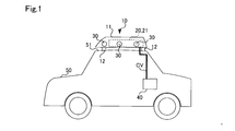
- FIG. 1 is an explanatory view showing an example of a vehicle equipped with the measuring device unit according to the first embodiment.
- FIG. 2 is an explanatory diagram showing a connection mode of the measuring device unit according to the first embodiment to the vehicle control device.
- FIG. 3 is a block diagram showing a functional configuration of the data processing device according to the first embodiment.
- FIG. 4 is a flowchart showing a duplicate detection area setting process and an integrated data generation process flow executed by the data processing apparatus according to the first embodiment.
- FIG. 5 is an explanatory diagram schematically showing the detection area of the detector at the time of measurement.
- FIG. 6 is an explanatory diagram schematically showing the detection area of the detector at the time of calibration or diagnosis.
- FIG. 7 is an explanatory diagram schematically showing the data acquired by the detector.
- FIG. 8 is an explanatory diagram showing an example of communication band allocation in the integrated data before and after the change of the duplicate detection area.
- FIG. 9 is an explanatory diagram schematically showing the detection area of the detector under normal conditions.
- FIG. 10 is an explanatory diagram schematically showing a detection area of the detector at the time of failure.
- FIG. 11 is a flowchart showing a duplicate detection area setting process and an integrated data generation process flow executed by the data processing apparatus according to the second embodiment.
- FIG. 12 is an explanatory diagram schematically showing the data acquired by the detector.
- FIG. 13 is an explanatory diagram showing an example of communication band allocation in the integrated data before and after the change of the duplicate detection area.
- FIG. 14 is an explanatory diagram schematically showing a detection area of the detector at the time of failure.
- FIG. 15 is an explanatory diagram showing an example of communication band allocation in the integrated data before and after the change of the duplicate detection area.
- FIG. 16 is an explanatory diagram showing a connection mode of the measuring device unit according to another embodiment.
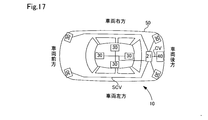
- FIG. 17 is an explanatory diagram showing an example in which the data processing device according to another embodiment is arranged inside the vehicle.
- FIG. 18 is an explanatory diagram showing an example in which a plurality of measuring device units according to other embodiments are provided.
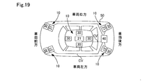
- FIG. 19 is an explanatory diagram showing an example in which a plurality of measuring device units and a vehicle control device according to another embodiment are provided.
- FIG. 20 is an explanatory diagram schematically showing a detection area of the detector during low-speed running.
- the in-vehicle measuring device unit and the integrated data generation method in the measuring device unit according to the present disclosure will be described below based on some embodiments.
- the vehicle-mounted measuring device unit 10 As shown in FIG. 1, the vehicle-mounted measuring device unit 10 according to the first embodiment is mounted on the vehicle 50 and used.
- the measuring device unit 10 may include at least a data processing device 21, and in the present embodiment, the measuring device unit 10 further includes a plurality of detectors 30 arranged around the main body 20, for example, front, back, left, right, and above. There is.
- the data processing device 21 is provided outside the vehicle 50 and is included in the main body 20.
- the main body 20 may be partially or wholly formed of a resin, for example, a non-metal material such as reinforced resin or carbon fiber, or may be partially or wholly formed of a metal material such as aluminum or stainless steel. ..
- the main body 20 may be further formed by using both a metal material and a non-metal material. For example, a plurality of components such as an upper and lower housings, a box body and a lid body are interposed with a resin or rubber sealing member. It is formed by letting and combining.
- the measuring device unit 10 further includes a frame (not shown) and a fixing mechanism 12 for fixing the measuring device unit 10 to the vehicle 50.
- the fixing mechanism 12 may be, for example, a mounting mechanism for mounting on the roof rail provided on the roof 51 of the vehicle 50, or mounting mechanism 12 mounted between the roof 51 of the vehicle 50 and the upper part of the door. It may be a mechanism.
- the data processing device 21 is provided inside the main body 20 having a waterproof structure.
- the detector 30 and the main body 20 can be easily mounted on the vehicle regardless of the shape of the vehicle 50.
- a vehicle control device 40 inside the vehicle is provided inside the vehicle 50.
- the vehicle control device 40 includes, for example, a driving support control device for executing driving support such as braking support, steering support, and driving support by using information about an object around the vehicle 50 input from the measuring device unit 10. It is equipped.
- the measuring device unit 10, specifically, the data processing device 21 and the vehicle control device 40 are connected by a single wiring CV.
- the number of wiring CVs may be sufficiently smaller than the number of detectors 30, and is preferably 1/10 or less of the total number of detectors 30, and more preferably one.
- the measuring device unit 10 includes a data processing device 21 in the main body 20 and a plurality of detectors 30 around the main body 20.
- the detectors are typically described with reference numerals 30, but the plurality of detectors 30 may include a camera 30C, a lidar 30L, and a millimeter wave radar 30M.
- the main body 20 covers the entire data processing device 21, and covers at least a part of the plurality of detectors 30.
- the data processing device 21 includes an integrated data generation unit 200, a plurality of detector input units 203, and one output unit 204.
- the plurality of detector input units 203 of the data processing device 21 are connected to the plurality of detectors 30, respectively.
- Each detector input unit 203 and each detector 30 are connected via a wiring SCV, and each detector input unit 203 corresponds to the shape of the connection terminal of the wiring SCV provided in each of the detectors 30C, 30L, and 30M. It is provided with a plurality of connecting portions C1, C2, and C3 having a different shape.
- Each detector input unit 203 is connected to the integrated data generation unit 200 via internal wiring.
- the detector input unit 203 is realized by a dedicated integrated circuit for mounting the physical layer of each communication protocol, that is, a PHY chip, and the communication protocol adopted by each detector 30 is adopted by the integrated data generation unit 200. Convert to Protocol Perform protocol conversion.
- Ethernet [registered trademark] 100M, 1G
- FPD-LINK FlatPanel DisplayLink
- GVIF GigabitVideoInterface
- LVDS Low voltage differential signaling
- FIG. 2 a plurality of detector input units 203, each of which has connection units C1, C2, and C3, are shown, but a plurality of connection units C1, C2, and C3 are provided and via one internal wiring.
- a single detector input unit 203 connected to the integrated data generation unit 200 may be used.
- the detector input unit 203 transmits the detection information detected by each detector 30 by the multiplexing communication including the frequency division multiplexing method and the time division multiplexing method to the integrated data generation unit 200.
- the camera 30C is an image pickup device including an image pickup element such as a CCD or an image pickup element array, and is a sensor that outputs external shape information or shape information of an object as image data as a detection result by receiving visible light.
- the lidar 30L is a sensor that detects the distance, relative velocity, and angle of the target with respect to the vehicle 50 by emitting infrared laser light and receiving the reflected light reflected by the target.
- the millimeter wave radar 30M is a sensor that detects the distance, relative velocity, and angle of the target with respect to the vehicle 50 by emitting millimeter waves and receiving the reflected wave reflected by the target.
- Each detector 30 may process the light receiving intensity and the receiving intensity obtained by the detection and output the detection data consisting of the detection point sequence and the image to the integrated data generation unit 200, or may be obtained by the detection.
- Raw data such as the received light intensity and the received intensity may be output to the integrated data generation unit 200 as they are.
- the integrated data generation unit 200 executes various processes such as image correction, lossless or lossy compression of the image, and demosaic. Further, processing such as image correction and demosaic may be executed in the vehicle control device 40.
- the detection data to be transmitted is requested from the vehicle control device 40 to the integrated data generation unit 200 according to the traveling state of the vehicle 50, and the raw data requested by the integrated data generation unit 200 is integrated.
- Integrated data may be generated and transmitted to the vehicle control device 40.
- the detection data to be transmitted means the detection data from the detector 30 determined based on the mounting position of the detector 30 and the type of the detector 30.
- the integrated data generation unit 200 selects the detection data according to the running state of the vehicle 50 or a predetermined condition, and the integrated data in which the corresponding raw data is integrated is generated, and the vehicle control device 40 receives the integrated data. May be sent.
- the output unit 204 of the data processing device 21 is connected to the vehicle control device 40 arranged in the vehicle 50 via the wiring CV.
- the output unit 204 is realized by a dedicated integrated circuit for mounting the physical layer of each communication protocol, that is, a PHY chip, and is adopted in the vehicle control device 40 with respect to the integrated data generated in the data processing device 21.
- the protocol conversion process for converting to the communication protocol is executed and transmitted to the vehicle control device 40.
- the number of wires input to the data processing device 21 is the number of wires corresponding to the number of detectors 30, whereas in the present embodiment, the number of wires output from the data processing device 21 is one. Yes, the number of wires between the data processing device 21 and the vehicle control device 40 is reduced.
- communication protocols such as Ethernet (10G or more), LVDS (FPD-LINK, GVIF, GMSL), and HDBASE-T are used.
- Ethernet 10G or more
- LVDS FPD-LINK, GVIF, GMSL
- HDBASE-T high-power digital signalling
- the difference between the hardware side of the connection terminal shape of the wiring of each detector 30 and the software side of the communication protocol of each detector 30 is absorbed. -Because it can be dealt with, it is possible to provide a virtual common input unit for the vehicle control device 40.
- the data processing device 21 includes an integrated data generation unit 200, a duplicate detection area setting unit 201, a memory 202, a detector input unit 203, an output unit 204, and an information input unit 205.
- the data processing device 21 is realized in hardware by an integrated circuit.
- the integrated data generation unit 200 is realized by a single pre-programmed integrated circuit such as FPGA, ASIC or Soc, or a plurality of integrated circuits.
- the integrated data generation unit 200 executes an integrated data generation process for generating integrated data to be transmitted to the vehicle control device 40 using the detection data acquired from the detector 30.
- the integrated data is data in which the amount of detection data from each detector 30 is adjusted so as not to exceed the communication band between the data processing device 21 and the vehicle control device 40, and each detection is performed according to the conditions.
- Each detection data of the amount of data allocated to the vessel 30 is included.
- the data capacity that does not exceed the communication band means at least one of the communication capacity that the wiring CV can transmit and the data capacity that the vehicle control device 40 can process.
- the condition means a state of the detector 30 such as at the time of measurement, at the time of calibration or diagnosis, or at the time of failure.
- the overlap detection area setting unit 201 dynamically sets the overlap detection area among a plurality of arbitrary detectors 30 among the plurality of detectors 30.
- the overlap detection area during measurement is set at the time of measurement, and the overlap detection area during non-measurement is set larger than the overlap detection area during measurement at the time of diagnosis or calibration.
- the data processing device 21 and the vehicle control device 40 are connected by a single wire, and the communication band, that is, the upper limit of the amount of transmitted data is limited.
- the duplicate detection area means that the detection areas of each detector 30 overlap, that is, the detection data is redundant, and the large duplicate detection area means an increase in the amount of detection data. Therefore, the communication band is defined at the time of measurement, that is, the overlap detection area is set in consideration of the upper limit, and the overlap detection area formed by the detector 30 to be calibrated at the time of non-measurement such as diagnosis or calibration is expanded. This will improve the calibration accuracy.
- the communication band means, for example, the amount of data that can be transmitted per unit time, similar to terms such as transmission rate and transfer speed, and generally involves overwriting of a buffer or discarding data on the receiving side. It is determined by the amount of data that can be processed per unit time without any problem.
- the plurality of arbitrary detectors 30 among the plurality of detectors 30 are not limited to the following, but are, for example, two adjacent detectors 30 among the three adjacent detectors 30.
- the measurement time means an object detection time such as measurement of a distance to an object around the vehicle 50 and discrimination of the type of the object by the measuring device unit 10, and means a state in which the state of the detector 30 itself is not discriminated.
- the time of diagnosis or the time of calibration means the time of executing the diagnostic process of the operating state of the detector 30, the time of executing the calibration process of detecting the deviation amount of the optical axis of the detector 30, and the state of not executing the object detection. do.
- the integrated data generation unit 200 uses the duplicate detection area setting unit 201 when generating the integrated data.
- Duplicate detection area during measurement by reducing the detection data corresponding to at least a part of the duplicate detection area from the detection data of at least one of a plurality of arbitrary detectors 30 according to the set duplicate detection area. Is realized, and the duplicate detection region at the time of non-measurement is realized by maintaining the detection data corresponding to the duplicate detection region in the detection data of the plurality of arbitrary detectors 30.
- the integrated data generation unit 200 When each detector 30 has a scanning function, the integrated data generation unit 200 also instructs the scanning control actuator of each detector 30 to increase or decrease the scanning angle range, so that the overlap detection region at the time of measurement is detected. And the overlap detection area at the time of non-measurement may be realized.
- the memory 202 stores the duplicate detection area setting information ASI for setting the duplicate detection area in a non-volatile and read-only manner.
- the overlapping detection area setting information ASI is information that associates the target detector whose detection area should be changed with the area expansion amount of the target detector with respect to the reference detection area.
- the target detector may be a predetermined detector 30 included in a plurality of adjacent detectors 30, or may be a plurality of adjacent detectors 30.
- the duplicate detection area setting unit 201 acquires the target detector and the area expansion amount in the target detector with reference to the duplicate detection area setting information ASI in the memory 202, and outputs the area expansion amount to the integrated data generation unit 200.
- the duplicate detection area setting information ASI may be provided in the duplicate detection area setting unit 201.
- a plurality of and a plurality of types of detectors 30 are connected to the detector input unit 203 via a detection signal line as wiring. Detection data is input from the detector 30.
- a vehicle control device 40 is connected to the output unit 204 via an integrated data signal line as wiring. Integrated data is output to the vehicle control device 40.
- a vehicle CAN 55 is connected to the information input unit 205 via wiring. Driving information and environmental information are input from the vehicle CAN55.
- the vehicle control device 40 controls the output of the internal combustion engine or the motor in response to the accelerator pedal operation by the driver or regardless of the accelerator pedal operation by the driver via a driving support device (not shown), and is controlled by the driver. Braking by the braking device is realized regardless of the operation of the braking pedal, or steering by the steering device is realized regardless of the operation of the steering wheel by the driver.
- the duplicate detection area setting process and the integrated data generation process executed by the data processing device 21 according to the first embodiment will be described.
- the processing routine shown in FIG. 4 is started to be executed, for example, when the control system of the vehicle is started or when the start switch is turned on.
- the processing routine shown in FIG. 4 may be started by triggering the occurrence of a calibration request instead of step S100.
- the measurement duplication detection area DOA is set as the default duplication detection area.
- the overlap detection area setting unit 201 determines whether or not a calibration request, that is, a calibration request has occurred (step S100).
- the calibration request is transmitted from the vehicle CAN 55 to the duplicate detection area setting unit 201 via the information input unit 205.
- the calibration request may be output from the vehicle control device 40 to the vehicle CAN55 at predetermined intervals, for example, every 200 km, every 30 days, and every 30 times of travel, or the fusion process using the detection data. From the result, when it is determined that the position shift has occurred between the two different detectors 30 or the detection data has not been obtained, the vehicle control device 40 may output the data to the vehicle CAN 55.
- a calibration request is output from the vehicle control device 40 to the data processing device 21 via the wiring CV. You may.
- the vehicle control device 40 saves the vehicle 50 on the shoulder when the vehicle 50 is stopped, for example, when the vehicle is stopped at a traffic light or when the vehicle is in a traffic jam, or when the vehicle 50 is an autonomous vehicle. Issuing a calibration request if the conditions are met.
- the calibration request may be issued by the integrated data generation unit 200 instead of the vehicle control device 40.
- the overlap detection area setting unit 201 waits until a calibration request is generated (step S100: No), and the overlap detection area setting unit 201 determines that a calibration request has been generated (step S100: Yes).
- Duplicate detection area setting information ASI is used to set a non-measurement duplicate detection area (step S102).
- the non-measurement duplicate detection area is set by using the overlap detection area setting information ASI to determine the target detector to which the detection area should be expanded and the expansion amount of the detection area of the target detector, that is, the extended detection area. Will be executed. Since the overlapping detection area is realized by overlapping the detection areas of the plurality of adjacent detectors 30, the measurement is performed by expanding the detection area of at least one of the plurality of adjacent detectors 30.
- Time overlap detection area A non-measurement time overlap detection area extended from DOA is set.
- the overlap detection region DOA at the time of measurement has a size shown in FIG. 5, for example.
- the anterior detector 30f, the intermediate detector 30c, and the posterior detector 30r include detection regions DA1, DA2, and DA3, respectively.
- the detection areas DA1, DA2 and DA3 at the time of measurement correspond to the reference detection area.
- the front detector 30f and the intermediate detector 30c have a measurement overlap detection region DOA in which the respective detection regions DA1 and DA2 overlap, and the intermediate detector 30c and the rear detector 30r have the respective detection regions DA2 and DA3. It is set to have overlapping detection areas DOA during measurement.
- the front side detector 30f is determined as the target detector, and the expansion amount of the detection area DA1 of the front side detector 30f, that is, the expansion detection area DA1e is determined.
- the non-measurement overlap detection area DOAe is set.
- the set non-measurement overlap detection area DOAe can be realized as follows.
- the detection area of the front detector 30f is extended to the intermediate detector 30c side.
- the non-measurement overlap detection region DOAe can be realized.
- the detection area of the camera 30C can be substantially expanded in software, that is, on the data as follows.
- FIG. 7 schematically shows the image data acquired by the camera 30C in association with the angle of view.
- the additional data used during calibration is clipped during measurement, and only the data used during measurement is used as the detection data acquired by the detector 30.
- the additional data used during calibration is the detection data corresponding to at least a part of the measurement overlap detection area DOA, that is, the maximum measurement overlap detection area DOA that can be acquired by the detector 30 to the minimum measurement overlap detection area DOA. It means the detection data corresponding to the overlap detection region DOA at the time of measurement of any size up to. That is, the duplicate detection region DOA also exists at the time of measurement, and the detection data corresponding to the duplicate detection region DOA at the time of measurement is included in the data used at the time of measurement.
- the angle of view of the camera 30C that is, the detection area is limited to the range shown as the data used at the time of measurement, and the detection area DA1 and the overlap detection area DOA at the time of measurement in FIG. 5 are realized.
- the angle of view of the camera 30C is widened by maintaining the originally acquired additional data used at the time of calibration as effective detection data without clipping, and the detection area DA1 + extended detection area DA1e in FIG. 6 is widened. As a result, the non-measurement overlap detection region DOAe is realized.
- the clipping amount is set to 0 according to the expansion amount of the detection area determined by the overlap detection area setting unit 201.
- the clipping amount may be appropriately set without using all the additional use data at the time of calibration, that is, the additional use data at the time of calibration may be partially used.
- the angle of view of the camera 30C can be set to an arbitrary angle of view
- the extended detection area DA1e can be set to an arbitrary size.
- the integrated data generation unit 200 acquires the detection data from each detector 30 (step S104).
- the detection data acquired from each detector 30 is unclipping detection data including the additional use data at the time of calibration in FIG. 7.
- the integrated data generation unit 200 generates integrated data including additional data used during calibration and outputs the integrated data to the vehicle control device 40 (step S106).
- the integrated data generation unit 200 dynamically changes the ratio of each detected data from the plurality of arbitrary detectors 30 to the integrated data to generate the integrated data. Specifically, the target detector identified by the duplicate detection area setting unit 201, in FIG. 6, the detection data from the front side detector 30f is maintained as it is, that is, the target detection is performed without performing clipping processing on the detection data. A clipping process is executed for the detectors other than the device, in FIG.
- the integrated data generation unit 200 further reduces the detection data of the detectors 30 other than the front side detector 30f and the intermediate detector 30c to be calibrated.
- the detector 30 in which the amount of detected data is reduced is, for example, a detector 30 located on the right side of the vehicle, which is opposite to the left side of the vehicle in which the front side detector 30f and the intermediate detector 30c to be calibrated are present. , Front side detector 30f, intermediate detector 30c and rear side detector 30r and the same type of camera 30C. As a result, as shown in FIG.
- the amount of detection data of the camera 1 meaning the front side detector 30f is increased, and the amount of detection data of the camera 2 and the camera 3 meaning the intermediate detector 30c and the rear side detector 30r is increased.
- Integrated data is generated that is maintained and the amount of other camera detection data is reduced.
- the amount of detection data of the rear detector 30r that does not share the extended overlap detection region DOAe may also be reduced.
- the integrated data transmitted to the vehicle control device 40 that is, the integrated data for calibration is used in the vehicle control device 40 for the calibration process of the front side detector 30f and the intermediate detector 30c.
- the calibration process can be executed, for example, by extracting the amount of deviation of the coordinate position of the same object in the extended overlap detection region DOAe and identifying the axis deviation detector causing the optical axis deviation.
- the axis deviation detector can be specified by extracting the deviation amount for the overlapping detection region between the adjacent detectors 30.
- the misalignment amount of the misalignment detector is applied as a calibration amount to the detection data acquired from the misalignment detector at the time of measurement, and the misalignment is eliminated or reduced.
- the duplication detection area setting unit 201 sets the duplication detection area at the time of measurement using the duplication detection area setting information ASI (step S108), and ends this processing routine.
- the setting of the duplicate detection area at the time of measurement is executed by determining the target detector whose detection area is expanded by using the overlap detection area setting information ASI and setting the expansion amount of the detection area of the target detector to 0. ..
- the overlap detection region DOA at the time of measurement shown in FIG. 5 is realized, and the vehicle control device 40 can execute the object detection process using the detector 30, that is, the distance measurement process and the driving support control process.
- the duplication detection area between the plurality of arbitrary detectors 30 among the plurality of detectors 30 is dynamically set, and the set duplication detection is performed. Since integrated data is generated using the detection data corresponding to the detection areas input from the plurality of detectors 30 according to the area, the amount of detection data can be suppressed and the accuracy of diagnosis and calibration of the detectors can be improved. Both improvements can be achieved. More specifically, the overlap detection area setting unit 201 included in the measuring device unit 10 dynamically measures the overlap detection area between the plurality of arbitrary detectors 30 among the plurality of detectors 30, that is, during measurement.
- the time overlap detection area is set, and the non-measurement overlap detection area DOAe larger than the measurement time overlap detection area DOA is set at the time of diagnosis or calibration.
- the overlap detection area is small, the detection area of each detector 30 becomes small, so that the amount of detection data of each detector 30 is reduced, and the integrated data including the detection data from each detector 30 in a desired ratio. Can be generated, and the detection accuracy of the object is improved.
- the overlap detection area is expanded and a larger overlap detection area is set than at the time of measurement, so that the accuracy of diagnosis or calibration can be improved.
- the detection area of the plurality of detectors 30 related to the diagnosis or calibration is increased, so that the amount of detection data is increased, but the amount of detection data of the plurality of unrelated detectors 30 is reduced. , It is possible to generate integrated data including the detection data from each detector 30 in a desired ratio.
- the case of performing calibration is described as an example, but the same can be applied to the time of executing diagnosis of the detector 30. That is, instead of the calibration request, the duplicate detection area setting process and the integrated data generation process shown in FIG. 4 may be executed by using the input of the diagnosis request from the vehicle control device 40 to the data processing device 21 as a trigger.
- the detector 30 generally has a self-diagnosis function, but a diagnosis using image data with high diagnostic accuracy has a high processing load and is not suitable for self-diagnosis in each detector 30. Further, the objective diagnosis using the duplicate detection region cannot be performed by the self-diagnosis function of each detector 30. Therefore, as described in the first embodiment, the diagnostic accuracy is improved by executing the diagnosis using the overlap detection region in the vehicle control device 40.
- the issuance of the diagnosis request may be under the same conditions as the calibration request, and the vehicle control device 40 or the overlap detection area receives the request from each detector 30 in response to the result of the self-diagnosis in each detector 30. It may be issued by the setting unit 201 itself.
- the camera 30C has been described as an example, but the same can be applied to the rider 30L and the millimeter wave radar 30M.
- the lidar 30L and the millimeter wave radar 30M generally have a scanning function, and the scanning range can be arbitrarily set within an allowable scanning range in terms of the configuration of the apparatus.
- the upper limit of the communication band may be exceeded. Therefore, by dynamically switching the overlap detection region between the measurement time and the non-measurement time, it is possible to suppress the amount of detected data and improve the calibration or diagnostic accuracy.
- the detection area of the intermediate detector 30c may be expanded in addition to the front side detector 30f. That is, when the detector to be calibrated is at least one of the front detector 30f and the intermediate detector 30c, the detection regions DA1 and DA2 of both the front detector 30f and the intermediate detector 30c related to the calibration process are May be extended. In this case, it is possible to reduce the amount of expansion of the detection area in each of the detectors 30f and 30c as compared with the case of expanding the detection area in any one of the detectors, and the overlap detection area is set. The degree of freedom is improved.
- the vehicle control device 40 executes the calibration process or the diagnostic process, but the data processing device 21 may execute the calibration process or the diagnostic process.
- the process is executed using the additional data used at the time of calibration, that is, using the overlap detection area DOAe at the time of non-measurement, and the integrated data is calibrated. It may be generated using the detection data in which the additional usage data is deleted at the time of operation. Also in this aspect, the amount of detected data can be reduced and the accuracy of calibration or diagnosis can be improved.
- the overlap detection area setting unit 201 expands the detection area of the other detectors of the plurality of arbitrary detectors at the time of failure when any one of the plurality of arbitrary detectors has failed.
- a plurality of detectors 30 arranged on the left side of the vehicle 50 that is, the front side detector 30f, the intermediate detector 30c, and the rear side detector 30r will be described as an example.
- the detectors 30f, 30c, 30r When the detectors 30f, 30c, 30r are operating normally, the detectors 30f, 30c, 30r have the detection regions DA1, DA2, DA3 shown in FIG. 9, respectively, and as a result, the front side detection is performed.
- An overlap detection region DOA during measurement is formed between the device 30f and the intermediate detector 30c, and between the intermediate detector 30c and the rear detector 30r, respectively, and between the front detector 30f and the rear detector 30r.
- the overlap detection region DOA at the time of measurement is not formed.
- the overlapping detection area among the plurality of detectors 30 that have not failed is moved. Is set.
- the plurality of arbitrary detectors 30 among the plurality of detectors 30 are not limited to the following, but may be, for example, two of the three adjacent detectors 30 except for the intermediate detector 30. Alternatively, it may be the other three detectors 30 other than one of the four adjacent detectors 30. More specifically, as shown in FIG. 10, when the intermediate detector 30c fails, the detection areas DA1 and DA3 of the front side detector 30f and the rear side detector 30r are expanded by the extended detection areas DA1e and DA3e, respectively. Then, a failure overlap detection region DOA13 is formed between the front side detector 30f and the rear side detector 30r.
- the duplicate detection area setting process and the integrated data generation process executed by the data processing device 21 according to the second embodiment will be described.
- the processing routine shown in FIG. 11 is started to be executed, for example, when the control system of the vehicle is started or when the start switch is turned on.
- the processing routine shown in FIG. 11 may be started by triggering the occurrence of failure detection instead of step S200. Further, at the start of execution of the processing routine shown in FIG. 11, the measurement duplication detection area DOA is set as the default duplication detection area.
- the duplicate detection area setting unit 201 determines whether or not a failure has occurred in the detector (step S200). The determination of whether or not a failure has occurred in the detector is executed by using the failure notification, the failure notification is determined by the vehicle control device 40, and is determined from the vehicle CAN 55 via the information input unit 205. It may be transmitted to the overlap detection area setting unit 201, and when the detector 30 determines a failure by self-diagnosis, the detector 30 may notify the overlap detection area setting unit 201 of the occurrence of a failure.
- the detection of the occurrence of a failure in the vehicle control device 40 is, for example, an execution result of a diagnostic process using the non-measurement overlap detection region DOAe described in the first embodiment, or a data loss or a decrease in signal strength during measurement.
- the detection of the occurrence of a failure may be determined by the data processing device 21, for example, the integrated data generation unit 200, based on data loss or a decrease in signal strength when generating integrated data. Further, the final determination may be made in the vehicle control device 40 by using these determination results in combination. The final determination may be, for example, a majority vote based on the number of failure determinations, or each determination result may be weighted and the final determination of failure occurrence may be executed when a predetermined threshold value is exceeded.
- the duplicate detection area setting unit 201 sets the duplicate detection area DOA at the time of measurement (step S210) when the detector has not failed normally (step S200: No), and ends this processing routine.
- the overlap detection area setting unit 201 determines that a failure of the detector has occurred (step S200: Yes)
- the overlap detection area setting unit 201 identifies the failure detector which is the detector in which the failure has occurred, and the overlap detection area setting information ASI. Is used to identify the detection area of the fault detector (step S202).
- the overlap detection area setting information ASI stores the arrangement information of each detector and the detection area of each detector in association with each other, and identifies the detection area of the failure detector identified by specifying the failure detector. can do.
- the detection area corresponds to the scanning range or angle of view range for which each detector is responsible for detection or monitoring.
- the overlap detection area setting unit 201 sets the failure overlap detection area DOA13 so as to supplement the detection area of the identified failure detector (step S204).
- the setting of the duplicate detection area DOA13 at the time of failure is performed by determining the target detector to which the detection area should be expanded and the expansion amount of the detection area of the target detector, that is, the extended detection area, by using the overlap detection area setting information ASI. Will be executed. More specifically with reference to FIG. 10, the front side detector 30f and the rear side detector 30r adjacent to the intermediate detector 30c as the failure detectors specified by using the overlap detection area setting information ASI are specified to detect the failure.
- the detection areas of the front side detector 30f and the rear side detector 30r are set so as to supplement the detection area DA2 of the device 30c, that is, the overlap detection area of the front side detector 30f and the rear side detector 30r, that is, the overlap detection at the time of failure.
- the region DOA 13 is set.
- the failure overlap detection area DOA13 is realized by the detection area of the front side detector 30f being the detection area DA1 + the extended detection area DA1e and the detection area of the rear side detector 30r being the detection area DA3 + the extended detection area DA3e. Will be done.
- the set failure overlap detection area DOA13 can be realized as follows.
- the detection areas of the front side detector 30f and the rear side detector 30r are intermediate detectors, respectively.
- the failure overlap detection region DOA13 can be realized.
- the detection area of the camera 30C can be substantially expanded in software, that is, on the data as follows.
- FIG. 12 schematically shows the image data acquired by the camera 30C.
- the clipping data in the normal state is clipped at the time of measurement, and only the normal data is used as the detection data acquired by the detector 30. ..
- the angle of view of the camera 30C that is, the detection area is limited to the range shown as the data used during measurement, and the detection areas DA1 to DA3 in FIG. 9 and the overlapping detection areas DOA at each measurement are realized.
- the normal state data is data corresponding to the detection area of each detector 30 in the normal state, and includes data corresponding to the detection area capable of forming the measurement overlap detection area DOA.
- the normal clipping data is data to be deleted in order to maintain the upper limit of the band of the integrated data in the normal state, and is the data excluding the normal time data among the data that can be acquired by the detector 30.
- the failure overlap detection area DOA13 is realized by maintaining the normal clipping data in the detection data of the detector that supplements the failure detector.
- the originally acquired normal clipping data is maintained as valid detection data, the angle of view of the camera 30C is widened, and the detection area DA1 + extended detection area DA1e and the detection area DA3 + extended detection in FIG. 10 are widened.
- the area DA3e is realized, and the overlap detection area DOA13 at the time of failure is realized.
- the integrated data generation unit 200 acquires the detection data from each detector 30 (step S206).
- the detection data acquired from each detector 30 is unclipping detection data including the normal clipping data in FIG. 12.
- the integrated data generation unit 200 generates integrated data including clipping data at the normal time, outputs the integrated data to the vehicle control device 40 (step S208), and ends the processing routine.
- the integrated data generation unit 200 realizes the measurement duplication detection area DOA set by the duplication detection area setting unit 201 by deleting the normal clipping data from the detection data of the plurality of arbitrary detectors, and a plurality of arbitrary detection areas DOA.
- the failure duplication detection area DOA13 set by the duplication detection area setting unit 201 is realized by maintaining the normal clipping detection data in the detection data of the detectors other than the failure detector among the detectors.
- the integrated data generation unit 200 is a failure target detector identified by the overlap detection area setting unit 201, and in FIG. 10, from the front side detector 30f and the rear side detector 30r adjacent to the intermediate detector 30c.
- the detection data of the above is maintained as it is, that is, the detection data is not clipped, and the detectors other than the front side detector 30f and the rear side detector 30r, in FIG. Clipping processing is executed for the detection data from the detector 30 to be used, and the detection data from the intermediate detector 30c, which is a failure detector, is not used even if it is acquired.
- the amount of data allocated to the camera 2 meaning the intermediate detector 30c is the largest for the camera 1 meaning the front side detector 30f and the camera 3 meaning the rear side detector 30r.
- Integrated data is generated that is allocated and the amount of detected data of the camera 1 and the camera 3 is increased.
- the integrated data transmitted to the vehicle control device 40 can be used in the vehicle control device 40 to perform an object detection process, that is, a distance measurement process and a driving support control process. If the detector 30 has a failure, the accuracy of the processing using the detection data from each detector 30 in the vehicle control device 40 is lowered, so that the driver is notified to urge maintenance. It is preferable that the display or sound, or the notification to the vehicle management center using the in-vehicle radio is executed.
- the measuring device unit 10 when any one of the plurality of arbitrary detectors 30 has failed, the plurality of arbitrary detectors 30 have failed. Since the failure overlap detection area DOA13 is set to expand the detection area of the detector 30 that has not been used to supplement the detection area of the failure detector, the amount of detection data can be suppressed and the object can be detected when the detector fails. It is possible to suppress or prevent a decrease in accuracy. More specifically, the overlap detection area setting unit 201 included in the measuring device unit 10 dynamically measures the overlap detection area between the plurality of arbitrary detectors 30 among the plurality of detectors 30, that is, normally.
- the time overlap detection area DOA is set, and the failure time overlap detection area DOA13 is set to supplement the detection area of the failure detector in the event of a failure.
- the detection area of each detector 30 becomes smaller, so that the amount of detection data of each detector 30 is reduced, and it becomes possible to generate integrated data including the detection data from each detector 30 in a desired ratio. , The detection accuracy of the object is improved.
- the overlap detection area is expanded and the overlap detection area is set to supplement the detection area of the failure detector, so that deterioration of the detection accuracy of the object can be suppressed or prevented.
- the measuring device unit in the third embodiment has the same configuration as the measuring device unit 10 according to the first embodiment, and thus has the same configuration as that in the first embodiment. The description of each configuration will be omitted by adding the same reference numerals as the reference numerals in 1.
- the detectors 30f, 30c, 30r, the lidar 31, and the millimeter-wave radar (not shown), which are cameras, cover the same area as shown in FIG. It is arranged like this.
- the intermediate detector 30c when the intermediate detector 30c is out of order, the information of the detection area DA2 that is not acquired by the failed intermediate detector 30c is arranged in the vicinity of the intermediate detector 30c, and the intermediate detector 30c is arranged.
- the detection region DA4 may be supplemented by a rider 31 that overlaps at least partially. More specifically, the resolution or resolution of the rider 31 is increased to supplement the detection data obtained by the intermediate detector 30c, which is the camera 30C.
- Both the camera 30C and the rider 31 can output pixel image data, and can complement each other with pixel information.
- the amount of detection data output by the rider 31 increases, but as shown in FIG. 15, the amount of data assigned to the camera 2 which is the intermediate detector 30c is the amount of data assigned to the rider 31.
- the failure of the camera 30C is compensated by the rider 31, but the failure of the rider 31 may be compensated by the camera 30C, and further, the millimeter-wave radar is similarly complemented with each other. May be executed.
- the complementary processing is not limited to the cancellation of clipping and the expansion of the detection area or the scanning range, and is also realized by, for example, increasing the frame rate of the detection data output from the detector 30 which has not failed. obtain.
- the front side detector 30f, the intermediate detector 30c, and the rear side detector 30r located on the left side of the vehicle 50 have been described as examples, but they are located on the front side, the right side, or the rear side of the vehicle 50. The same can be applied to a plurality of detectors 30 to be used. Further, the overlap detection area may be set in a combination such as front + left, front + right, rear + left, rear + right of the vehicle 50.
- the vehicle control device 40 is limited to the driving support control device.
- it may be various control devices such as a vehicle control device and a communication gateway control device in an in-vehicle network. In either case, there is an advantage that the number of wirings from the outside of the vehicle 50 to the inside of the vehicle 50 can be reduced.
- the measuring device unit 10 includes a data processing device 21 and a plurality of detectors 30, and the data processing device 21 is provided outside the vehicle 50.
- the data processing device 21 may be provided inside the vehicle 50 as shown in FIGS. 16 and 17.
- each detector 30 is directly connected to the data processing device 21 arranged inside the vehicle 50 via the wiring SCV.
- the technical effects obtained by each of the above-described embodiments can be obtained in the same manner. That is, the above-mentioned integrated data generation process and duplicate detection area setting process can be executed regardless of the physical mounting position of the data processing device 21.
- a plurality of measuring device units 10 including the data processing device 21 and the detector 30 may be arranged in the vehicle 50.
- a vehicle control device 40 is provided for each measuring device unit 10.
- the plurality of vehicle control devices 40 are connected to each other so as to be able to communicate with each other via the wiring ECV.
- one vehicle control device 40 is provided for each measuring device unit 10. Also in these embodiments, the technical effects obtained by each of the above-described embodiments can be obtained in the same manner.
- the allocation of the data amount of the target detector 30 in the integrated data is changed, that is, increased or reduced at the time of calibration or failure of the detector 30.
- the amount of data in the integrated data may be reduced according to the traveling state of the vehicle 50. For example, when the vehicle 50 is caught in a traffic jam and is traveling at a low speed, the amount of data of the camera 30C may be reduced as shown in FIG.
- the amount of imaging data is large, and even if the amount of imaging data is small during low-speed driving, that is, even if thinning is performed, the vehicle uses the detection results of the rider 30L and millimeter-wave radar 30M.
- Fifty controls, eg, driving assistance that follows the preceding vehicle, may be performed.
- the reduction in the amount of data can be realized, for example, by lowering the frame rate, expanding the clipping region in the detection region, narrowing the scanning range, or increasing the amount of data thinning out in the data processing apparatus 21.
- the data processing load in the subsequent processing device for example, the vehicle control device 40 can be reduced, and the power consumption can be suppressed.
- the detector 30 whose data amount is reduced in the integrated data is not limited to the camera 30C, depending on the detection data type required by the running state of the vehicle 50, and the data amount of the detection data of the rider 30L and the millimeter wave radar 30M. May be reduced.
- the integrated data generation process is realized by a pre-programmed integrated circuit such as FPGA, ASIC, or Soc, but the integrated process includes a process in which the CPU dynamically sets the duplicate detection area.
- the integrated data generation process may be realized by software, or may be realized by hardware by a discrete circuit. That is, the control unit and its method in each of the above embodiments are provided by a dedicated computer provided by configuring a processor and memory programmed to perform one or more functions embodied by a computer program. It may be realized. Alternatively, the controls and methods thereof described in the present disclosure may be implemented by a dedicated computer provided by configuring the processor with one or more dedicated hardware logic circuits.
- the controls and methods thereof described in the present disclosure consist of a combination of a processor and memory programmed to perform one or more functions and a processor composed of one or more hardware logic circuits. It may be realized by one or more dedicated computers. Further, the computer program may be stored in a computer-readable non-transitional tangible recording medium as an instruction executed by the computer.
Landscapes
- Engineering & Computer Science (AREA)
- Physics & Mathematics (AREA)
- Remote Sensing (AREA)
- Radar, Positioning & Navigation (AREA)
- General Physics & Mathematics (AREA)
- Computer Networks & Wireless Communication (AREA)
- Electromagnetism (AREA)
- Multimedia (AREA)
- Theoretical Computer Science (AREA)
- Traffic Control Systems (AREA)
- Radar Systems Or Details Thereof (AREA)
- Optical Radar Systems And Details Thereof (AREA)
- Testing Or Calibration Of Command Recording Devices (AREA)
Priority Applications (2)
| Application Number | Priority Date | Filing Date | Title |
|---|---|---|---|
| CN202180015258.7A CN115151838B (zh) | 2020-02-17 | 2021-02-08 | 车载用的测量装置单元以及综合数据生成方法 |
| US17/820,146 US20220390606A1 (en) | 2020-02-17 | 2022-08-16 | Vehicle-mounted measurement device unit and integrated data generation method in vehicle-mounted measurement device unit |
Applications Claiming Priority (2)
| Application Number | Priority Date | Filing Date | Title |
|---|---|---|---|
| JP2020-024168 | 2020-02-17 | ||
| JP2020024168A JP7283413B2 (ja) | 2020-02-17 | 2020-02-17 | 車載用の計測装置ユニットおよび車載用の計測装置ユニットにおける統合データ生成方法 |
Related Child Applications (1)
| Application Number | Title | Priority Date | Filing Date |
|---|---|---|---|
| US17/820,146 Continuation US20220390606A1 (en) | 2020-02-17 | 2022-08-16 | Vehicle-mounted measurement device unit and integrated data generation method in vehicle-mounted measurement device unit |
Publications (1)
| Publication Number | Publication Date |
|---|---|
| WO2021166718A1 true WO2021166718A1 (ja) | 2021-08-26 |
Family
ID=77390977
Family Applications (1)
| Application Number | Title | Priority Date | Filing Date |
|---|---|---|---|
| PCT/JP2021/004614 Ceased WO2021166718A1 (ja) | 2020-02-17 | 2021-02-08 | 車載用の計測装置ユニットおよび車載用の計測装置ユニットにおける統合データ生成方法 |
Country Status (4)
| Country | Link |
|---|---|
| US (1) | US20220390606A1 (https=) |
| JP (1) | JP7283413B2 (https=) |
| CN (1) | CN115151838B (https=) |
| WO (1) | WO2021166718A1 (https=) |
Families Citing this family (2)
| Publication number | Priority date | Publication date | Assignee | Title |
|---|---|---|---|---|
| JP7718304B2 (ja) * | 2022-03-24 | 2025-08-05 | トヨタ自動車株式会社 | 映像伝送システム、車両、および映像伝送方法 |
| JP2025125616A (ja) * | 2024-02-16 | 2025-08-28 | 株式会社小糸製作所 | センサシステム、移動体、センサシステムの制御方法、センサシステムの制御プログラム、および、コンピュータプログラムを記録したコンピュータ読み取り可能な記録媒体 |
Citations (4)
| Publication number | Priority date | Publication date | Assignee | Title |
|---|---|---|---|---|
| JP2015123899A (ja) * | 2013-12-26 | 2015-07-06 | トヨタ自動車株式会社 | 車両周辺状況推定装置 |
| US20190049958A1 (en) * | 2017-08-08 | 2019-02-14 | Nio Usa, Inc. | Method and system for multiple sensor correlation diagnostic and sensor fusion/dnn monitor for autonomous driving application |
| WO2019138964A1 (ja) * | 2018-01-09 | 2019-07-18 | パイオニア株式会社 | 制御装置、走査装置、制御方法、プログラム及び記憶媒体 |
| WO2019208271A1 (ja) * | 2018-04-25 | 2019-10-31 | 日立オートモティブシステムズ株式会社 | 電子制御装置、演算方法 |
Family Cites Families (17)
| Publication number | Priority date | Publication date | Assignee | Title |
|---|---|---|---|---|
| JP2000216765A (ja) * | 1999-01-22 | 2000-08-04 | Nec Corp | パタ―ン検出回路 |
| US7106421B2 (en) * | 2003-04-04 | 2006-09-12 | Omron Corporation | Method of adjusting axial direction of monitoring apparatus |
| JP3905116B2 (ja) * | 2004-02-03 | 2007-04-18 | 松下電器産業株式会社 | 検出領域調整装置 |
| US9714815B2 (en) * | 2012-06-19 | 2017-07-25 | Lockheed Martin Corporation | Visual disruption network and system, method, and computer program product thereof |
| JP6115104B2 (ja) * | 2012-12-04 | 2017-04-19 | アイシン精機株式会社 | 車両の制御装置、及び制御方法 |
| JP6458439B2 (ja) * | 2014-10-09 | 2019-01-30 | 株式会社デンソー | 車載カメラ較正装置、画像生成装置、車載カメラ較正方法、画像生成方法 |
| CN106471803A (zh) * | 2014-12-04 | 2017-03-01 | 深圳市大疆创新科技有限公司 | 成像系统及方法 |
| WO2017057057A1 (ja) * | 2015-09-30 | 2017-04-06 | ソニー株式会社 | 画像処理装置、画像処理方法、およびプログラム |
| US10267908B2 (en) * | 2015-10-21 | 2019-04-23 | Waymo Llc | Methods and systems for clearing sensor occlusions |
| US10451740B2 (en) * | 2016-04-26 | 2019-10-22 | Cepton Technologies, Inc. | Scanning lidar systems for three-dimensional sensing |
| KR102537598B1 (ko) * | 2016-10-11 | 2023-06-01 | 주식회사 에이치엘클레무브 | 전방감시장치, 전방감시장치를 이용한 운전지원장치 및 운전지원방법 |
| WO2018196001A1 (en) * | 2017-04-28 | 2018-11-01 | SZ DJI Technology Co., Ltd. | Sensing assembly for autonomous driving |
| JP6848725B2 (ja) * | 2017-06-29 | 2021-03-24 | 株式会社デンソー | 車両用の対象物検出装置および車両用の対象物検出装置における水平方向の軸ずれ判定方法 |
| US10656245B2 (en) * | 2017-09-05 | 2020-05-19 | Valeo Radar Systems, Inc. | Automotive radar sensor blockage detection using adaptive overlapping visibility |
| JP2020030121A (ja) * | 2018-08-23 | 2020-02-27 | 日本電産モビリティ株式会社 | 対象物検出装置、対象物検出システム |
| US11340335B2 (en) * | 2019-04-22 | 2022-05-24 | Byton North America Corporation | Multiple LIDAR processing methods and systems |
| US11983425B2 (en) * | 2019-11-12 | 2024-05-14 | Toyota Motor Engineering & Manufacturing North America, Inc. | Vehicular communications redundant data identification and removal |
-
2020
- 2020-02-17 JP JP2020024168A patent/JP7283413B2/ja active Active
-
2021
- 2021-02-08 CN CN202180015258.7A patent/CN115151838B/zh active Active
- 2021-02-08 WO PCT/JP2021/004614 patent/WO2021166718A1/ja not_active Ceased
-
2022
- 2022-08-16 US US17/820,146 patent/US20220390606A1/en active Pending
Patent Citations (4)
| Publication number | Priority date | Publication date | Assignee | Title |
|---|---|---|---|---|
| JP2015123899A (ja) * | 2013-12-26 | 2015-07-06 | トヨタ自動車株式会社 | 車両周辺状況推定装置 |
| US20190049958A1 (en) * | 2017-08-08 | 2019-02-14 | Nio Usa, Inc. | Method and system for multiple sensor correlation diagnostic and sensor fusion/dnn monitor for autonomous driving application |
| WO2019138964A1 (ja) * | 2018-01-09 | 2019-07-18 | パイオニア株式会社 | 制御装置、走査装置、制御方法、プログラム及び記憶媒体 |
| WO2019208271A1 (ja) * | 2018-04-25 | 2019-10-31 | 日立オートモティブシステムズ株式会社 | 電子制御装置、演算方法 |
Also Published As
| Publication number | Publication date |
|---|---|
| CN115151838A (zh) | 2022-10-04 |
| US20220390606A1 (en) | 2022-12-08 |
| JP7283413B2 (ja) | 2023-05-30 |
| JP2021128116A (ja) | 2021-09-02 |
| CN115151838B (zh) | 2025-02-25 |
Similar Documents
| Publication | Publication Date | Title |
|---|---|---|
| US10576968B2 (en) | Control system, relay device and control method | |
| JP5991332B2 (ja) | 衝突回避制御装置 | |
| US20200269876A1 (en) | Autonomous driving control device and method for autonomous driving control of vehicles | |
| WO2023162491A1 (en) | Distributed processing of vehicle sensor data | |
| US12187295B2 (en) | Vehicle measuring device unit and method of generating integrated data in vehicle measuring device unit | |
| US11027678B2 (en) | On-board system and detector hub | |
| WO2015104915A1 (ja) | 車載カメラ画像処理装置 | |
| US20220390606A1 (en) | Vehicle-mounted measurement device unit and integrated data generation method in vehicle-mounted measurement device unit | |
| CN114715055A (zh) | 车辆网络通信系统和方法 | |
| WO2020095636A1 (ja) | 駐車支援装置及び駐車支援方法 | |
| EP4005890B1 (en) | Vehicle control system | |
| US20230408688A1 (en) | System and method for drive control of front ultra-sonic sensors | |
| JP2022001475A (ja) | 車両制御装置 | |
| JP6891082B2 (ja) | 物体距離検出装置 | |
| CN118701087B (zh) | 人机交互装置、系统、方法、程序产品及车辆 | |
| EP3933799B1 (en) | Arithmetic operation device for automobiles | |
| WO2021020294A1 (ja) | 車両制御システム | |
| EP4592860A1 (en) | Central computing unit, function execution method, device, storage medium, and vehicle | |
| JP2021084493A (ja) | 車載ネットワークシステム | |
| JP2018107620A (ja) | 撮像システム、移動体、および制御方法 | |
| US12420813B2 (en) | Electronic control unit | |
| EP4005891B1 (en) | Vehicle control system | |
| CN222859429U (zh) | 车辆冗余控制系统及车辆 | |
| JP7164483B2 (ja) | 電子制御装置、制御システム | |
| CN117597281A (zh) | 自动制动控制装置以及自动制动处理程序 |
Legal Events
| Date | Code | Title | Description |
|---|---|---|---|
| 121 | Ep: the epo has been informed by wipo that ep was designated in this application |
Ref document number: 21757211 Country of ref document: EP Kind code of ref document: A1 |
|
| NENP | Non-entry into the national phase |
Ref country code: DE |
|
| 122 | Ep: pct application non-entry in european phase |
Ref document number: 21757211 Country of ref document: EP Kind code of ref document: A1 |
|
| WWG | Wipo information: grant in national office |
Ref document number: 202180015258.7 Country of ref document: CN |