WO2021161923A1 - ロール表面の状態判定支援装置、ロール表面の異物除去装置及びロール表面の異物除去方法 - Google Patents
ロール表面の状態判定支援装置、ロール表面の異物除去装置及びロール表面の異物除去方法 Download PDFInfo
- Publication number
- WO2021161923A1 WO2021161923A1 PCT/JP2021/004365 JP2021004365W WO2021161923A1 WO 2021161923 A1 WO2021161923 A1 WO 2021161923A1 JP 2021004365 W JP2021004365 W JP 2021004365W WO 2021161923 A1 WO2021161923 A1 WO 2021161923A1
- Authority
- WO
- WIPO (PCT)
- Prior art keywords
- vibration
- foreign matter
- roll
- unit
- state
- Prior art date
- Legal status (The legal status is an assumption and is not a legal conclusion. Google has not performed a legal analysis and makes no representation as to the accuracy of the status listed.)
- Ceased
Links
Images




Classifications
-
- C—CHEMISTRY; METALLURGY
- C23—COATING METALLIC MATERIAL; COATING MATERIAL WITH METALLIC MATERIAL; CHEMICAL SURFACE TREATMENT; DIFFUSION TREATMENT OF METALLIC MATERIAL; COATING BY VACUUM EVAPORATION, BY SPUTTERING, BY ION IMPLANTATION OR BY CHEMICAL VAPOUR DEPOSITION, IN GENERAL; INHIBITING CORROSION OF METALLIC MATERIAL OR INCRUSTATION IN GENERAL
- C23C—COATING METALLIC MATERIAL; COATING MATERIAL WITH METALLIC MATERIAL; SURFACE TREATMENT OF METALLIC MATERIAL BY DIFFUSION INTO THE SURFACE, BY CHEMICAL CONVERSION OR SUBSTITUTION; COATING BY VACUUM EVAPORATION, BY SPUTTERING, BY ION IMPLANTATION OR BY CHEMICAL VAPOUR DEPOSITION, IN GENERAL
- C23C2/00—Hot-dipping or immersion processes for applying the coating material in the molten state without affecting the shape; Apparatus therefor
-
- B—PERFORMING OPERATIONS; TRANSPORTING
- B08—CLEANING
- B08B—CLEANING IN GENERAL; PREVENTION OF FOULING IN GENERAL
- B08B1/00—Cleaning by methods involving the use of tools
- B08B1/10—Cleaning by methods involving the use of tools characterised by the type of cleaning tool
- B08B1/16—Rigid blades, e.g. scrapers; Flexible blades, e.g. wipers
- B08B1/165—Scrapers
-
- C—CHEMISTRY; METALLURGY
- C23—COATING METALLIC MATERIAL; COATING MATERIAL WITH METALLIC MATERIAL; CHEMICAL SURFACE TREATMENT; DIFFUSION TREATMENT OF METALLIC MATERIAL; COATING BY VACUUM EVAPORATION, BY SPUTTERING, BY ION IMPLANTATION OR BY CHEMICAL VAPOUR DEPOSITION, IN GENERAL; INHIBITING CORROSION OF METALLIC MATERIAL OR INCRUSTATION IN GENERAL
- C23C—COATING METALLIC MATERIAL; COATING MATERIAL WITH METALLIC MATERIAL; SURFACE TREATMENT OF METALLIC MATERIAL BY DIFFUSION INTO THE SURFACE, BY CHEMICAL CONVERSION OR SUBSTITUTION; COATING BY VACUUM EVAPORATION, BY SPUTTERING, BY ION IMPLANTATION OR BY CHEMICAL VAPOUR DEPOSITION, IN GENERAL
- C23C2/00—Hot-dipping or immersion processes for applying the coating material in the molten state without affecting the shape; Apparatus therefor
- C23C2/04—Hot-dipping or immersion processes for applying the coating material in the molten state without affecting the shape; Apparatus therefor characterised by the coating material
- C23C2/06—Zinc or cadmium or alloys based thereon
-
- C—CHEMISTRY; METALLURGY
- C23—COATING METALLIC MATERIAL; COATING MATERIAL WITH METALLIC MATERIAL; CHEMICAL SURFACE TREATMENT; DIFFUSION TREATMENT OF METALLIC MATERIAL; COATING BY VACUUM EVAPORATION, BY SPUTTERING, BY ION IMPLANTATION OR BY CHEMICAL VAPOUR DEPOSITION, IN GENERAL; INHIBITING CORROSION OF METALLIC MATERIAL OR INCRUSTATION IN GENERAL
- C23C—COATING METALLIC MATERIAL; COATING MATERIAL WITH METALLIC MATERIAL; SURFACE TREATMENT OF METALLIC MATERIAL BY DIFFUSION INTO THE SURFACE, BY CHEMICAL CONVERSION OR SUBSTITUTION; COATING BY VACUUM EVAPORATION, BY SPUTTERING, BY ION IMPLANTATION OR BY CHEMICAL VAPOUR DEPOSITION, IN GENERAL
- C23C2/00—Hot-dipping or immersion processes for applying the coating material in the molten state without affecting the shape; Apparatus therefor
- C23C2/34—Hot-dipping or immersion processes for applying the coating material in the molten state without affecting the shape; Apparatus therefor characterised by the shape of the material to be treated
- C23C2/36—Elongated material
- C23C2/40—Plates; Strips
-
- C—CHEMISTRY; METALLURGY
- C23—COATING METALLIC MATERIAL; COATING MATERIAL WITH METALLIC MATERIAL; CHEMICAL SURFACE TREATMENT; DIFFUSION TREATMENT OF METALLIC MATERIAL; COATING BY VACUUM EVAPORATION, BY SPUTTERING, BY ION IMPLANTATION OR BY CHEMICAL VAPOUR DEPOSITION, IN GENERAL; INHIBITING CORROSION OF METALLIC MATERIAL OR INCRUSTATION IN GENERAL
- C23C—COATING METALLIC MATERIAL; COATING MATERIAL WITH METALLIC MATERIAL; SURFACE TREATMENT OF METALLIC MATERIAL BY DIFFUSION INTO THE SURFACE, BY CHEMICAL CONVERSION OR SUBSTITUTION; COATING BY VACUUM EVAPORATION, BY SPUTTERING, BY ION IMPLANTATION OR BY CHEMICAL VAPOUR DEPOSITION, IN GENERAL
- C23C2/00—Hot-dipping or immersion processes for applying the coating material in the molten state without affecting the shape; Apparatus therefor
- C23C2/50—Controlling or regulating the coating processes
- C23C2/51—Computer-controlled implementation
-
- C—CHEMISTRY; METALLURGY
- C23—COATING METALLIC MATERIAL; COATING MATERIAL WITH METALLIC MATERIAL; CHEMICAL SURFACE TREATMENT; DIFFUSION TREATMENT OF METALLIC MATERIAL; COATING BY VACUUM EVAPORATION, BY SPUTTERING, BY ION IMPLANTATION OR BY CHEMICAL VAPOUR DEPOSITION, IN GENERAL; INHIBITING CORROSION OF METALLIC MATERIAL OR INCRUSTATION IN GENERAL
- C23C—COATING METALLIC MATERIAL; COATING MATERIAL WITH METALLIC MATERIAL; SURFACE TREATMENT OF METALLIC MATERIAL BY DIFFUSION INTO THE SURFACE, BY CHEMICAL CONVERSION OR SUBSTITUTION; COATING BY VACUUM EVAPORATION, BY SPUTTERING, BY ION IMPLANTATION OR BY CHEMICAL VAPOUR DEPOSITION, IN GENERAL
- C23C2/00—Hot-dipping or immersion processes for applying the coating material in the molten state without affecting the shape; Apparatus therefor
- C23C2/50—Controlling or regulating the coating processes
- C23C2/52—Controlling or regulating the coating processes with means for measuring or sensing
Definitions
- the present disclosure relates to a roll surface condition determination support device provided in a molten metal plating bath, a foreign matter removing device on the roll surface, and a foreign matter removing method on the roll surface.
- a continuous hot-dip plating line in which a steel strip is continuously immersed in a hot-dip metal plating bath and the surface of the steel strip is plated, it adheres to a roll provided in the bath (hereinafter, appropriately referred to as a "bath roll"). Surface flaws may occur due to foreign matter (including coarsened precipitates).
- a wiper device in order to remove foreign substances adhering to the surface of the roll in the bath, there is a technique for keeping the surface of the sink roll clean by a wiper device as described in Japanese Patent Application Laid-Open No. 61-164268.
- the wiper device described in Japanese Patent Application Laid-Open No. 61-164268 does not consider grasping the state of removing foreign substances on the surface of the roll in the bath. That is, regarding the work of removing foreign matter existing on the surface of the roll in the bath, even if the wiper device described in Japanese Patent Application Laid-Open No. 61-164268 is applied to such work, the state of removing foreign matter on the roll surface including the completion of removal is included. There was a problem that it was not possible to judge.
- the present disclosure discloses a roll surface state determination support device, a roll surface foreign matter removing device, and a method for removing foreign matter on the roll surface, which can grasp the foreign matter removing state on the surface of the roll provided in the molten metal plating bath.
- the purpose is to provide.
- the roll surface state determination support device includes a vibration detection unit that detects vibration of a scraper portion having a blade that comes into contact with the surface of a roll provided in a molten metal plating bath, and the scraper portion. It is provided with a vibration unit that generates vibration detected by the vibration detection unit at a distant position and determines the removal state of foreign matter existing on the roll surface based on the generated vibration.
- the roll surface state determination support device of the second aspect of the present disclosure is the roll surface state determination support device of the first aspect, when the vibration state detected by the vibration detection unit is set to the first state.
- a conversion unit that converts the first state into a second state generated by the vibration unit is further provided.
- the foreign matter removing device on the roll surface of the third aspect of the present disclosure includes a scraper portion having a blade provided in the molten metal plating bath and having a blade that abuts on the surface of the roll to remove the foreign matter on the roll surface, and the first aspect or The roll surface state determination support device of the second aspect is provided.
- the foreign matter removing device on the roll surface of the fourth aspect of the present disclosure includes a scraper portion having a blade that comes into contact with the surface of the roll provided in the molten metal plating bath to remove foreign matter on the roll surface, and the scraper portion.
- the drive unit that moves the scraper unit along the axial direction of the roll, and the vibration detected by the vibration detection unit, the roll is moved to a predetermined position in the axial direction. It is provided with a movement control unit that controls the drive unit so as to move the scraper unit to remove the foreign matter.
- the foreign matter removing device on the roll surface according to the fifth aspect of the present disclosure is the foreign matter removing device on the roll surface according to any one of the first to fourth aspects, and the hot-dip metal plating bath is a hot-dip galvanizing bath.
- the method for removing foreign matter on the roll surface includes a contact step of bringing the blade of the scraper portion provided with the blade into contact with the surface of the roll provided in the molten metal plating bath, and the scraper portion.
- a vibration detection step for detecting the vibration generated in the scraper portion and a vibration of the scraper portion detected at a position away from the scraper portion are generated, and foreign matter existing on the surface of the roll is removed based on the generated vibration.
- the state determination step of determining the state and the removing step of removing the foreign matter by the scraper portion based on the determined removal state of the foreign matter are included.
- the method for removing foreign matter on the roll surface according to the seventh aspect of the present disclosure is the method for removing foreign matter on the roll surface according to the sixth aspect, when the vibration state detected in the vibration detection step is set to the first state.
- the method for removing foreign matter on the roll surface includes a contact step of bringing the blade of the scraper portion provided with the blade into contact with the surface of the roll provided in the molten metal plating bath, and the scraper portion.
- the method for removing foreign matter on the roll surface according to the ninth aspect of the present disclosure is the method for removing foreign matter on the roll surface according to any one of the sixth to eighth aspects, wherein the hot-dip metal plating bath is a hot-dip galvanizing bath.
- a roll surface state determination support device a roll surface foreign matter removing device, and a roll capable of grasping the foreign matter removing state of the roll surface of the roll provided in the molten metal plating bath.
- a method for removing foreign matter on the surface can be provided.
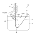
- FIG. 1 is a layout diagram showing an example of a schematic configuration of a molten metal-plated steel strip manufacturing apparatus 10 according to the present embodiment.
- the molten metal-plated steel strip manufacturing apparatus 10 continuously immerses the steel strip 1 in the plating bath 11 and performs a molten metal plating treatment to coat the surface of the steel strip 1 with a plating film. Is an apparatus for forming a molten metal plated steel strip 1A.
- the steel strip 1 is an example of a metal strip to be plated with the molten metal M.
- the type of the steel strip 1 is not particularly limited, and may be, for example, mild steel or high-strength steel.
- the plating tank 12 stores a plating bath 11 made of molten metal M.
- the molten metal M constituting the plating bath 11 include simple substances of Zn, Al, Sn, and Pb, or alloys thereof.
- the molten metal M can be added to these metals or alloys with non-metal elements such as Si and P, typical metal elements such as Ca, Mg and Sr, and Ti, V, Cr, Mn, Fe, Co, Ni and Cu. Those containing transition metal elements such as, etc. are also included.
- hot-dip zinc is used as the hot-dip metal M forming the plating bath 11 and hot-dip zinc is adhered to the surface of the steel strip 1 to manufacture the hot-dip metal-plated steel strip 1A will be described.
- the molten metal plated steel strip manufacturing apparatus 10 includes a snout 13, a sink roll 14, support rolls 15A and 15B, a gas wiping nozzle 16, and an induction heating apparatus. 17 and a foreign matter removing device 100 on the surface of the roll are provided.
- the snout 13 is a tubular member having an upper end connected to the outlet side of an annealing furnace (not shown) and the lower end immersed in the plating bath 11 and inclined.
- the snout 13 covers the steel strip 1 from the outside, and the inside of the snout 13 has a non-oxidizing atmosphere. As a result, contact between the surface of the steel strip 1 after annealing and the atmosphere is avoided, and oxidation is suppressed.
- the sink roll 14 is arranged below the plating bath 11.
- the sink roll 14 has a diameter larger than that of the support rolls 15A and 15B.
- the sink roll 14 rotates clockwise as shown by the transport of the steel strip 1, and vertically upward in the transport direction of the steel strip 1 introduced obliquely downward into the plating bath 11 through the snout 13. Change to.
- the support rolls 15A and 15B are arranged above the sink roll 14 in the plating bath 11, and the steel strip 1 which is changed in direction by the sink roll 14 and is pulled upward in the vertical direction is sandwiched from both the left and right sides.
- the support rolls 15A and 15B suppress the vibration of the steel strip 1 that is pulled up.
- the support rolls 15A and 15B may be provided only one without pairing, or three or more support rolls 15A and 15B may be provided. Alternatively, the arrangement of the support rolls 15A and 15B may be omitted.
- the gas wiping nozzle 16 injects a gas such as air onto the surface of the steel strip 1 in order to adjust the basis weight of the molten metal M with respect to the steel strip 1.
- Gas compressed by a compressor or the like (not shown) is introduced into the gas wiping nozzle 16.
- the gas wiping nozzles 16 are arranged on both sides of the steel strip 1 in the thickness direction, are on the downstream side of the support rolls 15A and 15B in the transport direction of the steel strip 1, and are located at a predetermined height from the bath surface of the plating bath 11. It is provided in.
- the gas injected from the gas wiping nozzle 16 is sprayed onto both surfaces of the steel strip 1 pulled upward in the vertical direction from the plating bath 11, and the excess molten metal M is scraped off.
- the amount of molten metal M attached to the surface of the steel strip 1 is adjusted to an appropriate amount, and the film thickness of the molten metal M adhering to the surface of the steel strip 1 is adjusted.
- the induction heating device 17 is provided on the downstream side of the steel strip 1 in the transport direction with respect to the gas wiping nozzle 16, and heat-treats the steel strip 1. Specifically, induction heating coils connected to a high-frequency power source (not shown) are provided on both sides of the steel strip 1 in the thickness direction. By heating by the induction heating device 17, the temperature near the surface of the steel strip 1 is raised to about 500 degrees, and alloying occurs between the molten metal M adhering to the surface of the steel strip 1 and the steel strip 1. As a result, an alloyed galvanized film is formed on the surface of the steel strip 1.
- the steel strip 1 is moved by a drive source (not shown), and each part in the apparatus is passed through the plate.
- the steel strip 1 is introduced obliquely downward into the plating bath 11 through the snout 13, and goes around the sink roll 14 to change the transport direction upward in the vertical direction.
- the steel strip 1 passes between the support rolls 15A and 15B, rises, and is pulled out of the plating bath 11.
- the excess molten metal M adhering to the steel strip 1 is scraped off by the pressure of the gas sprayed from the gas wiping nozzle 16, and the amount of the molten metal M adhering to the surface of the steel strip 1 is a predetermined grain amount. Is adjusted to.
- the induction heating device 17 promotes alloying between the molten metal M and the steel strip 1, and an alloyed plating film is formed on the surface of the steel strip 1.
- the molten metal-plated steel strip manufacturing apparatus 10 continuously immerses the steel strip 1 in the plating bath 11 to plate the molten metal M, thereby plating the molten metal with a predetermined grain amount.
- Manufacture steel strip 1A Manufacture steel strip 1A.
- various foreign substances are present on the surface of the roll in the plating bath 11 (hereinafter, the support rolls 15A and 15B and the sink roll 14 may be simply referred to as rolls in the present specification). May be done.
- top dross Fe 2 Al 5 Zn x
- bottom dross Fe Zn 3 , Fe Zn 7 , Fe 5 Zn 21 or Fe 3 Zn 10
- scum Zn or Al oxide
- the alloy component in the plating bath 11 is precipitated on the roll surface and coarsened.
- the molten metal-plated steel strip manufacturing apparatus 10 includes a foreign matter removing apparatus 100 on the roll surface.
- the foreign matter removing device 100 on the roll surface removes foreign matter existing on the roll surface. Specifically, the foreign matter removing device 100 on the roll surface scrapes off the foreign matter on the roll surface by pressing the scraper portion 110, which is a spatula-shaped member, toward the roll surface. Details of the foreign matter removing device 100 on the roll surface will be described later.
- FIG. 1 shows an example in which the foreign matter removing device 100 on the roll surface is provided for the support roll 15B, the sink roll 14 and the support roll 15A may also be provided.
- the schematic configuration of the molten metal-plated steel strip manufacturing apparatus 10 according to the present embodiment has been described above.
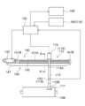
- FIG. 2 is a diagram showing a schematic configuration of a foreign matter removing device 100 on the roll surface according to the present embodiment.
- FIG. 3 is a diagram showing a schematic configuration of a foreign matter removing device 100 on the roll surface according to the present embodiment, and is a cross-sectional view taken along the line AA'in FIG.
- the foreign matter removing device 100 on the roll surface according to the present embodiment includes a scraper unit 110, a vibration detecting unit 120, and a vibrating unit 160.
- the vibration detection unit 120 and the vibration unit 160 constitute the state determination support device 118 according to the present embodiment.
- the state determination support device 118 is a device that supports determination of a foreign matter removal state on the roll surface.
- the scraper portion 110 is a spatula-shaped member that is pressed against the roll surface provided in the plating bath 11.
- the scraper portion 110 includes a blade 111 and a rod 113.
- the blade 111 is a metal flat plate member that comes into contact with the surface of the roll.
- the tip portion 111A of the flat plate-shaped portion of the blade 111 is brought into contact with the roll surface.
- the width of the blade 111 in the roll axial direction is shorter than the axial length of the roll.
- the abutting position of the blade 111 is not particularly limited as long as it does not interfere with the transportation of the steel strip 1.
- the blade 111 is configured to abut on the top or side of the roll.
- the blade 111 is made of, for example, a tool steel such as SKD11 or SKH51, a stainless steel such as SUS304L or SUS316L, or a Co-based alloy such as Stellite # 6 or Stellite # 21 (note that "Stellite” is a registered trademark. be).
- the rod 113 is a rod-shaped member extending from the main body 130 toward the roll. One end 113A of the rod 113 is supported by the main body 130, and the blade 111 is supported by the other end 113B of the rod 113.
- the shape or material of the rod 113 is not particularly limited as long as it can support the blade 111 in the plating bath 11.
- the scraper portion 110 is made movable toward the roll surface by an air cylinder 115.
- the air cylinder 115 is connected to the rod 113, and the rod 113 is displaced by the air cylinder 115, so that the tip portion 111A of the blade comes into contact with the roll surface or separates from the roll surface.
- the vibration detection unit 120 detects the vibration generated in the scraper unit 110. Since such vibration corresponds to the removal state of foreign matter existing on the roll surface, the vibration detection unit 120 detects the vibration to grasp the foreign matter removal state on the roll surface. Specifically, when the scraper portion 110 is brought into contact with the roll surface, friction is generated between the scraper portion 110 and the roll, and the friction causes vibration of the rod 113. Further, vibration is also generated in the rod 113 by overcoming a step caused by a relatively large foreign matter. Such vibration changes according to the removal state of the foreign matter existing on the roll surface.
- the vibration generated in the scraper portion 110 is large.
- the vibration generated in the scraper portion 110 is reduced due to the reduction of the frictional force and the height difference between the scraper portion 110 and the roll. In this way, by detecting the change in the strength (amplitude or vibration energy) of the vibration in the rod 113 of the scraper portion 110, the state of removing foreign matter on the roll surface can be grasped.
- the vibration detection unit 120 is provided in the intermediate portion 113C of the rod 113.
- the vibration generated in the scraper portion 110 propagates from the other end 113B of the rod 113 to one end 113A.
- the vibration detection unit 120 is provided on the rod 113, the vibration detection unit 120 is not limited to this, and for example, the vibration detection unit 120 may be provided on the connecting portion between the rod 113 and the air cylinder 115. good.
- the vibration detection unit 120 is a uniaxial acceleration sensor, and detects the vibration generated in the scraper unit 110 by detecting the acceleration in the direction orthogonal to or parallel to the longitudinal direction of the rod 113 generated in the rod 113.
- the vibration detection unit 120 is a piezoelectric type acceleration sensor.
- the main body 130 is a frame portion provided on the outside of the plating bath 11 and supporting the scraper 110 and the like at a predetermined position. Specifically, the main body 130 supports one end 113A of the rod 113 of the scraper 110. Further, the main body 130 is provided with an air cylinder 115 and a drive unit 140 described later.
- the foreign matter removing device 100 on the surface of the roll further includes a drive unit 140.
- the drive unit 140 moves the scraper unit 110 along the axial direction of the roll. By moving the scraper portion 110 along the axial direction of the roll, foreign matter on the surface of the roll can be removed at an arbitrary position in the axial direction of the roll.
- the drive unit 140 includes a screw feed mechanism 141, a drive source 143, and a guide shaft 145.
- the screw feed mechanism 141 includes a screw shaft 141A whose axial direction is provided along the axial direction of the roll, and a support portion 141B that rotatably supports both ends of the screw shaft 141A.
- the screw shaft 141A is a rod-shaped member in which threads are provided on the outer peripheral surface at a predetermined pitch. As shown in FIG. 3, the screw shaft 141A is inserted while being screwed into the bracket 141C to which the air cylinder 115 of the scraper portion 110 is attached. Further, a drive source 143 is connected to the end of the screw shaft 141A, and the screw shaft 141A is configured to be rotated by the drive source 143. As a result, the rotation of the screw shaft 141A causes the scraper portion 110 to be screwed forward and move along the axial direction of the roll.
- the guide shaft 145 is a rod-shaped member provided along the axial direction of the roll in parallel with the screw shaft 141A. Both ends of the guide shaft 145 are supported by the support portion 141B of the screw shaft 141A. As shown in FIG. 3, the guide shaft 145 supports a bracket 145A to which one end 113A of the rod 113 of the scraper portion 110 is attached. The guide shaft 145 stabilizes the movement of the scraper portion 110 in the roll axis direction, while the air cylinder 115 presses the scraper portion 110 against the roll (see the double-headed arrow in FIG. 3).
- the foreign matter removing device 100 on the roll surface includes a control unit 150.
- the control unit 150 controls the operation of the foreign matter removing device on the roll surface. Specifically, as shown in FIG. 2, the control unit 150 acquires the detection result from the vibration detection unit 120 and controls the drive unit 140 and the air cylinder 115.
- an operation unit 180 is connected to the control unit 150, and controls the drive unit 140 and the air cylinder 115 based on the input from the operation unit 180 operated by the operator.
- control unit 150 outputs the detection result from the vibration detection unit 120 to the vibration unit 160, which will be described later.
- the format of the detection result from the vibration detection unit 120 is not limited, but may be, for example, a change in vibration intensity with time.
- the vibration unit 160 generates the vibration detected by the vibration detection unit 120 at a position away from the scraper unit 110 based on the detection result from the vibration detection unit 120.
- the vibrating unit 160 generates a vibration that reproduces the vibration detected by the vibration detecting unit 120 at a position away from the scraper unit 110.
- the vibrating unit 160 includes an amplification unit 161 and a vibration generating unit 163.
- the detection result of the vibration detection unit 120 is input to the vibration unit 160 located at a position away from the scraper unit 110 by a wired connection such as an electric cable.
- the detection result of the vibration detection unit 120 is amplified by the amplification unit 161 of the vibration detection unit 160, and then input to the vibration generation unit 163.
- the vibration generating unit 163 generates physical vibration based on the input signal.
- the vibrating unit 160 generates vibration that reproduces the change in the strength (change in amplitude) of the vibration detected by the vibration detecting unit 120.
- FIG. 4 is a diagram schematically showing the result of spectrum analysis of the vibration directly detected on the rod 113 of the scraper portion 110 before the foreign matter on the roll surface is removed.
- FIG. 5 is a diagram schematically showing the result of spectrum analysis of the vibration directly detected on the rod 113 of the scraper portion 110 after the foreign matter on the roll surface is removed.
- FIG. 4 before the foreign matter on the roll surface is removed, a high-intensity peak is detected in a wide range of frequencies, and a large vibration is generated.
- FIG. 4 before the foreign matter on the roll surface is removed, a high-intensity peak is detected in a wide range of frequencies, and a large vibration is generated.
- the intensity of the peak decreases after the foreign matter on the roll surface is removed.
- the peak intensity was greatly reduced. In this way, when the foreign matter on the roll surface is removed, the magnitude (amplitude) of the vibration in the scraper portion 110 decreases.
- FIG. 6 is a diagram schematically showing the result of spectrum analysis of the vibration in which the vibration detected in the rod 113 of the scraper unit 110 before the foreign matter on the roll surface is removed is reproduced by the vibration unit 160.
- FIG. 7 is a diagram schematically showing the result of spectrum analysis of vibration in which the vibration detected in the rod 113 of the scraper unit 110 after the foreign matter on the roll surface is removed is reproduced by the vibration unit 160.
- FIG. 6 even in the result of the spectrum analysis of the vibration reproduced by the vibrating unit 160, a high intensity peak is detected in a wide range of frequencies before the foreign matter on the roll surface is removed, and the large peak is detected. Vibration is occurring.
- FIG. 7 after the foreign matter on the roll surface is removed, the intensity of the peak is reduced, and the intensity of the peak is significantly reduced, particularly in the low frequency region.
- the vibrating unit 160 can realize the state of removing foreign matter on the roll surface at a position away from the scraper unit 110.
- An example of the exciter unit 160 is an electrokinetic exciter.
- the vibrating unit 160 a vibrating table having a vibrating surface that can be touched by an operator or the like can be mentioned.
- the vibrating unit 160 is provided at a position away from the scraper unit 110.
- the vibrating unit 160 is provided around the plating tank 12 or in the operator room of the operation line.
- the vibrating unit 160 reproduces the vibration generated in the scraper unit 110, so that the state of removing foreign matter on the roll surface can be grasped. That is, the vibrating unit 160 reproduces the change in the strength of the vibration, so that it is understood that foreign matter remains on the roll surface when the vibration of the vibrating unit 160 is large. On the other hand, when the vibration of the vibrating portion 160 is small, it is understood that the foreign matter on the roll surface has been removed.
- the foreign matter removing device 100 on the roll surface can grasp the removed state with the same criteria as the manual foreign matter removal. That is, when the operator uses a tool such as a scraper to remove the foreign matter on the roll surface, the state of removing the foreign matter on the roll surface is grasped by feeling the vibration of the scraper. By reproducing the vibration by the vibrating unit 160, even in the foreign matter removing device 100 on the roll surface, the operator or the like can detect and grasp the foreign matter removing state by the vibration.
- the schematic configuration of the foreign matter removing device 100 on the roll surface according to the present embodiment has been described above.
- FIG. 8 is a flowchart of a method for removing foreign matter on the roll surface according to the present embodiment.
- the scraper portion 110 is brought into contact with the roll surface (S101).
- the blade 111 provided at the other end 113B of the rod 113 of the scraper portion 110 is brought into contact with the surface of the roll.
- the scraper portion 110 starts removing foreign matter on the roll surface.
- the scraper unit 110 is moved by the operator operating the operation unit 180.
- vibration detection unit 120 S103
- the vibration of the rod 113 detected in step S103 is reproduced as vibration at a position away from the scraper portion 110 by the exciting portion 160 (S105).
- the removal state of foreign matter existing on the surface of the roll is grasped based on the vibration reproduced by the vibrating unit 160 in step S105 (S107). That is, the removing state of the foreign matter on the roll surface is grasped by the operator who is in contact with the vibrating portion 160.
- the operator feels the vibration of the vibrating portion 160 and determines that the removal of foreign matter on the roll surface is not sufficient, the operator does not move the position of the scraper portion 110 in the roll axis direction (that is, moves it). Without), the scraper unit 110 at that position continues to remove foreign matter.
- the scraper unit 110 removes the foreign matter at the same position until the operator determines that the foreign matter removal is completed based on the vibration of the exciting part 160. Continue.
- the operation unit 180 is operated to change the position of the scraper unit 110 in the roll axis direction, and the scraper unit 110 exists on the roll surface at another position in the roll axis direction. Removes foreign matter (S109).
- the operator can grasp the state of removing foreign matter on the surface of the roll provided in the hot-dip galvanizing bath 11 by the vibration of the vibrating portion 160, the foreign matter on the surface of the roll can be removed.
- the removal state including the completion of foreign matter removal.
- the vibration detected by the vibration detecting unit 120 is transmitted to the vibrating unit 160 via the control unit 150 to reproduce the vibration, but the present disclosure is limited to this configuration. Not done.
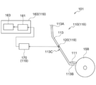
- the vibration detected by the vibration detecting unit 120 may be transmitted to the vibrating unit 160 via the converting unit 170 to reproduce the vibration.
- the foreign matter removing device 101 includes a conversion unit 170, and the conversion unit 170 takes such a first state when the state of vibration detected by the vibration detection unit 120 is set as the first state. Is converted into a second state reproduced by the vibrating unit 160. As shown in FIG.
- the conversion unit 170 is provided between the vibration detection unit 120 and the vibration unit 160 on the electric circuit.
- the conversion unit 170 electrically converts the detection result from the vibration detection unit 120 and outputs it to the vibration detection unit 160.
- the conversion unit 170 converts the frequency as the first state detected by the vibration detection unit 120 into the frequency as the second state that can be reproduced by the vibration unit 160.
- the conversion unit 170 converts the signal related to the frequency among the detection results from the vibration detection unit 120 into a signal related to the frequency reproducible by the vibration unit 160, and outputs the signal to the vibration unit 160. ..
- the vibration state of the scraper unit 110 By converting the vibration state of the scraper unit 110 into a vibration state that can be reproduced by the vibration unit 160 by the conversion unit 170, the vibration state that is optimal for reproduction by the vibration unit 160 is obtained, and foreign matter on the roll surface is obtained. It becomes easy to grasp the removal state.
- the frequency as the second state that can be reproduced by the vibrating unit 160 includes, for example, a frequency within a range that can be perceived by humans.
- the vibration reproduced by the vibrating unit 160 enables a human being to grasp the removal state of foreign matter on the roll surface.
- the conversion unit 170 may have a function as a filter for removing noise from the detection result from the vibration detection unit 120. Further, as shown in FIG.
- the vibration detecting unit 120, the vibrating unit 160, and the converting unit 170 constitute a state determination support device 119 that supports the determination of the foreign matter removing state on the roll surface.
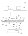
- the foreign matter removing device 102 of the present embodiment is used in the molten metal plated steel strip manufacturing apparatus 10 like the foreign matter removing device 100 of the first embodiment.
- the control unit 151 determines the state of the roll surface based on the detection result of the vibration detection unit 120, and moves the scraper unit 110 in the roll axis direction according to the determination result. ..
- the foreign matter removing device 102 does not include the vibrating unit 160 of the foreign matter removing device 100 of the first embodiment because the control unit 151 determines the foreign matter removing state on the roll surface.
- the foreign matter removing device 102 of the present embodiment includes an operation unit 180 for manual operation of the scraper unit 110.
- the control unit 151 of the present embodiment acquires the detection result from the vibration detection unit 120 and controls the drive unit 140 and the air cylinder 115.
- the control unit 151 functions as a movement control unit that moves the scraper unit 110 to a predetermined position in the roll axis direction by controlling the drive unit 140 based on the vibration detected by the vibration detection unit 120.
- the control unit 151 acquires the detection result from the vibration detection unit 120, and if the detection result exceeds a preset threshold value, determines that the removal of foreign matter on the roll surface is not completed.
- the scraper portion 110 is not moved in the roll axis direction, and foreign matter removal on the roll surface is continued at the same position in the roll axis direction.
- the control unit 151 determines that the removal of foreign matter on the roll surface is completed, and positions the scraper unit 110 at another position in the roll axis direction. Move.
- the above threshold value is a value when it is determined that foreign matter is attached by manual removal of foreign matter.
- an acceleration sensor is used as the vibration detection unit 120. Therefore, when the effective value of the acceleration detected by the acceleration sensor exceeds a preset threshold value, the control unit 151 determines that foreign matter is attached to the roll surface.
- the control unit 151 may determine the state of removing foreign matter on the roll surface by determining that foreign matter is attached when the detection result from the vibration detection unit 120 exceeds the threshold value a predetermined number of times within a predetermined time. ..
- the control unit 151 drives the drive source 143 and moves the scraper unit 110 to a predetermined position in the axial direction of the roll via the screw feed mechanism 141. Then, the control unit 151 operates the air cylinder 115 to press the scraper unit 110 toward the surface of the roll. As a result, the scraper portion 110 removes foreign matter at a predetermined position in the axial direction of the roll.
- FIG. 12 is a flowchart of a method for removing foreign matter on the roll surface according to the present embodiment.
- the scraper portion 110 is brought into contact with the roll surface (S121).
- vibration is generated in the rod 113 of the scraper unit 110, and the vibration is detected by the vibration detection unit 120 (S123).
- step S125 the control unit 151 compares the detection result detected in step S123 with the threshold value. As a result, the control unit 151 grasps the removal state of the foreign matter existing on the roll surface, and determines whether or not the removal of the foreign matter on the roll surface is completed (S127). If it is not determined that the removal of the foreign matter is completed, the process returns to step S125, and the foreign matter removal state is grasped. On the other hand, when it is determined in step S127 that the removal of foreign matter on the roll surface is completed, the position of the scraper portion 110 in the axial direction of the roll is changed based on the vibration detected in step S123, and the position in the roll axis direction is changed. The foreign matter existing on the roll surface is removed at the position of (S129).
- the control unit 151 determines that foreign matter remains on the roll surface, and removes the foreign matter by the scraper unit 110 at the position in the roll axial direction. continue.
- the control unit 151 determines that the foreign matter on the roll surface has been removed, and changes the position of the scraper unit 110 in the roll axial direction.
- the scraper unit 110 may be moved at a predetermined pitch to change the position in the roll axis direction. Further, the scraper unit 110 may be moved to a position in the roll axis direction where the vibration is relatively large, based on the vibration state detected by the vibration detection unit 120.
- control unit 151 can grasp the foreign matter removal state on the surface of the roll provided in the hot-dip galvanizing bath 11 from the detection result from the vibration detection unit 120. As a result, regarding the work of removing foreign matter on the roll surface, it is possible to determine the removal state including the completion of foreign matter removal.
- the vibration unit 160 is a vibration table having a vibration surface that can be touched by a human being, but the present disclosure is not limited to such an example.
- it may be a vibrator that can be grasped by a human.
- the controller as the operation unit 180 used when moving the scraper unit 110 as the vibration unit 160 may be configured to have a vibration function.
- the vibration detection unit 120 is a piezoelectric type acceleration sensor
- the vibration detection unit 120 only needs to be able to detect the vibration generated in the rod 113, particularly.
- a non-contact type vibration detection unit 120 such as a microphone or a laser displacement meter may be used to detect an acoustic signal or displacement caused by vibration of the rod 113.
- the vibration detection unit 120 may be a sensor attached to a robot arm that can contact the scraper unit 110 to detect displacement due to vibration. Further, such a robot arm may be a slave arm in the master / slave manipulator. In this case, the master arm in the master / slave manipulator, to which the displacement of the slave arm is transmitted, may function as the excitation unit 160.
- the operator determines the foreign matter removing state of the roll surface based on the vibration of the vibrating unit 160, and in the foreign matter removing device 101 of the second embodiment, the control unit 151. Determines the foreign matter removing state on the roll surface based on the detection result from the vibration detection unit 120, but the present disclosure is not limited to this configuration.
- the case where the control unit determines the foreign matter removing state on the roll surface is set as the automatic operation mode, and the operator sets the case where the operator determines the foreign matter removing state on the roll surface based on the vibration of the vibration exciting unit 160.
- the manual operation mode may be set when the foreign matter removal state is determined, and these modes may be switched.
- the vibration detected by the vibration detection unit is generated (in other words, reproduced) by the vibration detection unit, but the present disclosure is not limited to this configuration.
- an operator or the like can detect a change in vibration, instead of the vibration section, for example, a speaker that reproduces the vibration detected by the vibration detection section as sound and displays it audibly, or a speaker that detects the vibration detected by the vibration detection section.
- a vibration reproducing unit such as a display that visually displays a signal related to the change may be used.
- a scraper portion having a blade that abuts on the surface of a roll provided in a hot-dip galvanizing bath, and a scraper portion.
- a vibration detection unit that detects the vibration of the scraper unit,
- Appendix 2 The device for removing foreign matter on the surface of a roll in a hot-dip galvanized bath according to Appendix 1, further comprising a vibration reproducing unit that is provided at a position away from the scraper unit and reproduces the vibration detected by the vibration detecting unit.
- Appendix 4 A drive unit that moves the scraper unit along the axial direction of the roll, and a drive unit. Appendix 1 to 3 further include a movement control unit that controls the drive unit so as to move the scraper unit to a predetermined position in the axial direction of the roll based on the vibration detected by the vibration detection unit.
- the device for removing foreign matter on the surface of a roll in a hot-dip galvanizing bath according to any one of the above items.
- Appendix 6 It further includes a vibration reproduction step of reproducing the detected vibration of the scraper portion.
- Appendix 7 When the vibration state detected in the vibration detection step is set to the first state, A conversion step of converting the first state into a second state reproduced in the vibration reproduction step, The method for removing foreign matter on the surface of a roll in a hot-dip galvanizing bath according to Appendix 6, further comprising.
Landscapes
- Chemical & Material Sciences (AREA)
- Engineering & Computer Science (AREA)
- Chemical Kinetics & Catalysis (AREA)
- Materials Engineering (AREA)
- Mechanical Engineering (AREA)
- Metallurgy (AREA)
- Organic Chemistry (AREA)
- Computer Hardware Design (AREA)
- Coating With Molten Metal (AREA)
Priority Applications (2)
| Application Number | Priority Date | Filing Date | Title |
|---|---|---|---|
| CN202180013577.4A CN115103925B (zh) | 2020-02-12 | 2021-02-05 | 辊表面的状态判定辅助装置、辊表面的杂质除去装置以及辊表面的杂质除去方法 |
| JP2022500377A JP7381962B2 (ja) | 2020-02-12 | 2021-02-05 | ロール表面の状態判定支援装置、ロール表面の異物除去装置及びロール表面の異物除去方法 |
Applications Claiming Priority (2)
| Application Number | Priority Date | Filing Date | Title |
|---|---|---|---|
| JP2020021245 | 2020-02-12 | ||
| JP2020-021245 | 2020-02-12 |
Publications (1)
| Publication Number | Publication Date |
|---|---|
| WO2021161923A1 true WO2021161923A1 (ja) | 2021-08-19 |
Family
ID=77292266
Family Applications (1)
| Application Number | Title | Priority Date | Filing Date |
|---|---|---|---|
| PCT/JP2021/004365 Ceased WO2021161923A1 (ja) | 2020-02-12 | 2021-02-05 | ロール表面の状態判定支援装置、ロール表面の異物除去装置及びロール表面の異物除去方法 |
Country Status (3)
| Country | Link |
|---|---|
| JP (1) | JP7381962B2 (https=) |
| CN (1) | CN115103925B (https=) |
| WO (1) | WO2021161923A1 (https=) |
Families Citing this family (1)
| Publication number | Priority date | Publication date | Assignee | Title |
|---|---|---|---|---|
| CN116603790B (zh) * | 2023-05-30 | 2025-09-19 | 张家港扬子江冷轧板有限公司 | 测张辊辊面清洁装置 |
Citations (5)
| Publication number | Priority date | Publication date | Assignee | Title |
|---|---|---|---|---|
| JPS61133369A (ja) * | 1984-11-30 | 1986-06-20 | Kawatetsu Kohan Kk | 溶融金属メツキ浴中ロ−ルの表面付着物の除去方法 |
| JPS61164268U (https=) * | 1985-03-29 | 1986-10-11 | ||
| EP0767253A1 (de) * | 1995-10-05 | 1997-04-09 | Comesi S.A.I.C. | Vorrichtung zur kontinuierlichen Heisstauchmetallisierung eines Stahlbandes |
| JP2001262300A (ja) * | 2000-03-16 | 2001-09-26 | Kawasaki Steel Corp | 溶融金属めっき浴中ロールの付着物除去装置、及び溶融金属めっき金属帯の押疵発生防止方法 |
| JP2002285307A (ja) * | 2001-03-27 | 2002-10-03 | Kawasaki Steel Corp | 浴中ロール表面付着物除去方法および装置 |
Family Cites Families (10)
| Publication number | Priority date | Publication date | Assignee | Title |
|---|---|---|---|---|
| JP3117936B2 (ja) * | 1997-06-25 | 2000-12-18 | 株式会社ドクター製作所 | 異物付着検出機能付きドクター装置 |
| CA2409159C (en) * | 2001-03-15 | 2009-04-21 | Nkk Corporation | Method for manufacturing hot-dip plated metal strip and apparatus for manufacturing the same |
| JP2010151715A (ja) * | 2008-12-26 | 2010-07-08 | Toray Ind Inc | ウェブとロール間の接触状態推定装置、接触状態推定方法およびフィルムの製造方法 |
| CN101948993A (zh) * | 2010-10-09 | 2011-01-19 | 苏州博恒浩科技有限公司 | 钢带振动热镀锌方法 |
| CN104947022B (zh) * | 2014-03-27 | 2017-08-15 | 上海梅山钢铁股份有限公司 | 一种连续热浸镀沉没辊积渣装置及积渣方法 |
| JP6450109B2 (ja) * | 2014-08-11 | 2019-01-09 | Jfeスチール株式会社 | 鋼帯の製造装置 |
| JP6451138B2 (ja) * | 2014-08-11 | 2019-01-16 | Jfeスチール株式会社 | 鋼帯の製造方法 |
| WO2017170239A1 (ja) * | 2016-03-29 | 2017-10-05 | 新日鐵住金株式会社 | 連続溶融金属めっき装置及び連続溶融金属めっき方法 |
| EP3604601A4 (en) * | 2017-03-31 | 2020-02-05 | JFE Steel Corporation | METHOD AND DEVICE FOR THE PRODUCTION OF A METAL-COVERED MELTDOWN TAPE STEEL |
| CN110598238A (zh) * | 2019-07-16 | 2019-12-20 | 西北工业大学 | 一种舱室结构振动响应再现方法 |
-
2021
- 2021-02-05 CN CN202180013577.4A patent/CN115103925B/zh active Active
- 2021-02-05 WO PCT/JP2021/004365 patent/WO2021161923A1/ja not_active Ceased
- 2021-02-05 JP JP2022500377A patent/JP7381962B2/ja active Active
Patent Citations (5)
| Publication number | Priority date | Publication date | Assignee | Title |
|---|---|---|---|---|
| JPS61133369A (ja) * | 1984-11-30 | 1986-06-20 | Kawatetsu Kohan Kk | 溶融金属メツキ浴中ロ−ルの表面付着物の除去方法 |
| JPS61164268U (https=) * | 1985-03-29 | 1986-10-11 | ||
| EP0767253A1 (de) * | 1995-10-05 | 1997-04-09 | Comesi S.A.I.C. | Vorrichtung zur kontinuierlichen Heisstauchmetallisierung eines Stahlbandes |
| JP2001262300A (ja) * | 2000-03-16 | 2001-09-26 | Kawasaki Steel Corp | 溶融金属めっき浴中ロールの付着物除去装置、及び溶融金属めっき金属帯の押疵発生防止方法 |
| JP2002285307A (ja) * | 2001-03-27 | 2002-10-03 | Kawasaki Steel Corp | 浴中ロール表面付着物除去方法および装置 |
Also Published As
| Publication number | Publication date |
|---|---|
| CN115103925A (zh) | 2022-09-23 |
| JP7381962B2 (ja) | 2023-11-16 |
| CN115103925B (zh) | 2025-06-06 |
| JPWO2021161923A1 (https=) | 2021-08-19 |
Similar Documents
| Publication | Publication Date | Title |
|---|---|---|
| Lei et al. | Analysis on welding characteristics of ultrasonic assisted laser welding of AZ31B magnesium alloy | |
| Wang et al. | Process characteristics and properties of AA2219 aluminum alloy welded by double pulsed VPTIG welding | |
| Luo et al. | Influence of pulsed arc on the metal droplet deposited by projected transfer mode in wire-arc additive manufacturing | |
| CN113414413A (zh) | 超声滚压调控激光增材制造沉积组织的方法与系统 | |
| TWI417428B (zh) | Continuous micro - anodic electroplating device and method thereof | |
| Zhu et al. | Energy characteristics of droplet transfer in wire-arc additive manufacturing based on the analysis of arc signals | |
| WO2021161923A1 (ja) | ロール表面の状態判定支援装置、ロール表面の異物除去装置及びロール表面の異物除去方法 | |
| JP5209749B2 (ja) | 抵抗溶接方法、抵抗溶接部材、抵抗溶接機とその制御装置、抵抗溶接機の制御方法とその制御プログラムおよび抵抗溶接の評価方法とその評価プログラム | |
| CN105195909A (zh) | 一种可细化焊接接头晶粒的超声电弧复合焊接方法 | |
| CN113943908A (zh) | 一种高频振动滚压强化激光熔覆层的装置及其使用方法 | |
| Chen et al. | Feasibility analysis of standing wave ultrasonic-Axial magnetic field hybrid for controlling GTAW arc characteristics | |
| WO2004046399A1 (ja) | 超音波衝撃処理機および超音波衝撃処理装置 | |
| JP2011194411A (ja) | スポット溶接方法及びスポット溶接継手 | |
| JP3890008B2 (ja) | 超音波ショットピーニング処理機、超音波ショットピーニング装置および超音波ショットピーニング処理方法 | |
| JP2021159989A (ja) | 溶接制御装置及び溶接制御方法 | |
| CN114871608A (zh) | 一种超声波辅助电弧点焊装置及使用方法 | |
| Qi et al. | Microstructure and properties of γ-TiAl fabricated by in-situ alloying assisted double-wire arc additive manufacturing | |
| KR20190078660A (ko) | 접합용 알루미늄 합금 제품 제조 방법 | |
| WO2004046398A1 (ja) | 超音波衝撃処理機および超音波衝撃処理装置 | |
| Zhao et al. | Optimisation of welding parameters for ultrasonically assisted resistance spot welding of pure titanium Grade 2 and aluminium alloy 5754 | |
| AU2006243159B2 (en) | Method for forming a tight-fitting silver surface on an aluminium piece | |
| Li et al. | Effect of Single and Double Pulse MIG Welding Process Parameters on Microstructure and Properties of Aluminium Alloy | |
| CN218656819U (zh) | 一种增材制造去应力装置 | |
| CN113909688A (zh) | 用于调节两相比例的双相不锈钢焊接方法及焊接系统 | |
| Can et al. | Design and Implementation of PLC Based Special Purpose Machine for Surface Coating |
Legal Events
| Date | Code | Title | Description |
|---|---|---|---|
| 121 | Ep: the epo has been informed by wipo that ep was designated in this application |
Ref document number: 21754604 Country of ref document: EP Kind code of ref document: A1 |
|
| WWE | Wipo information: entry into national phase |
Ref document number: 202217045835 Country of ref document: IN |
|
| ENP | Entry into the national phase |
Ref document number: 2022500377 Country of ref document: JP Kind code of ref document: A |
|
| NENP | Non-entry into the national phase |
Ref country code: DE |
|
| 122 | Ep: pct application non-entry in european phase |
Ref document number: 21754604 Country of ref document: EP Kind code of ref document: A1 |
|
| WWG | Wipo information: grant in national office |
Ref document number: 202180013577.4 Country of ref document: CN |