WO2021161406A1 - 固定子、電動機、圧縮機、空気調和機、及び固定子の製造方法 - Google Patents
固定子、電動機、圧縮機、空気調和機、及び固定子の製造方法 Download PDFInfo
- Publication number
- WO2021161406A1 WO2021161406A1 PCT/JP2020/005250 JP2020005250W WO2021161406A1 WO 2021161406 A1 WO2021161406 A1 WO 2021161406A1 JP 2020005250 W JP2020005250 W JP 2020005250W WO 2021161406 A1 WO2021161406 A1 WO 2021161406A1
- Authority
- WO
- WIPO (PCT)
- Prior art keywords
- coil
- phase
- coils
- slot
- phase coil
- Prior art date
- Legal status (The legal status is an assumption and is not a legal conclusion. Google has not performed a legal analysis and makes no representation as to the accuracy of the status listed.)
- Ceased
Links
Images

















Classifications
-
- H—ELECTRICITY
- H02—GENERATION; CONVERSION OR DISTRIBUTION OF ELECTRIC POWER
- H02K—DYNAMO-ELECTRIC MACHINES
- H02K3/00—Details of windings
- H02K3/04—Windings characterised by the conductor shape, form or construction, e.g. with bar conductors
- H02K3/28—Layout of windings or of connections between windings
-
- Y—GENERAL TAGGING OF NEW TECHNOLOGICAL DEVELOPMENTS; GENERAL TAGGING OF CROSS-SECTIONAL TECHNOLOGIES SPANNING OVER SEVERAL SECTIONS OF THE IPC; TECHNICAL SUBJECTS COVERED BY FORMER USPC CROSS-REFERENCE ART COLLECTIONS [XRACs] AND DIGESTS
- Y02—TECHNOLOGIES OR APPLICATIONS FOR MITIGATION OR ADAPTATION AGAINST CLIMATE CHANGE
- Y02T—CLIMATE CHANGE MITIGATION TECHNOLOGIES RELATED TO TRANSPORTATION
- Y02T10/00—Road transport of goods or passengers
- Y02T10/60—Other road transportation technologies with climate change mitigation effect
- Y02T10/64—Electric machine technologies in electromobility
Definitions
- This disclosure relates to a stator for motors.
- a stator having a three-phase coil is known (for example, Patent Document 1).
- the stator core disclosed in Patent Document 1 has 24 slots, the three-phase coil forms eight magnetic poles, and the number of slots for one magnetic pole is three.
- the coils of each phase are arranged every 3 slots (also referred to as 3 slot pitch), and are attached to the stator core by lap winding, and two coils of the same phase are arranged in each slot. ing.
- this stator has an advantage that 100% of the magnetic flux from the rotor can be utilized.
- the purpose of the present disclosure is to improve the balance of inductance in the three-phase coil and suppress the increase in torque ripple and the increase in loss in the motor.
- the stator according to one aspect of the present disclosure is Stator iron core and It is equipped with a three-phase coil attached to the stator core by distributed winding.
- the stator core has 9 ⁇ n slots (n is an integer of 1 or more).
- Each of the 9 ⁇ n slots is provided in an inner layer in which one of the three-phase coils is arranged and outside the inner layer in the radial direction, and one coil of the three-phase coils is provided.
- Including the outer layer on which The three-phase coil has 3 ⁇ n U-phase coils, 3 ⁇ n V-phase coils, and 3 ⁇ n W-phase coils at the coil end of the three-phase coil, and has 4 ⁇ n U-phase coils.
- Each of the 3 ⁇ n U-phase coils, the 3 ⁇ n V-phase coils, and the 3 ⁇ n W-phase coils is an n-set coil in which the first to third coils are a set. Including the group At the coil end, the first to third coils are arranged in this order in the circumferential direction at a pitch of 2 slots. At the coil ends, at least two of the first to third coils of at least one phase are adjacent to each other in the radial direction.
- the motor according to another aspect of the present disclosure is With the stator It includes a rotor arranged inside the stator.
- the compressor according to another aspect of the present disclosure is With a closed container With the compression device arranged in the closed container, It includes the electric motor that drives the compression device.
- the air conditioner according to another aspect of the present disclosure is With the compressor Equipped with a heat exchanger.
- the method for manufacturing a stator according to another aspect of the present disclosure A method for manufacturing a stator having a stator core having 9 ⁇ n slots (n is an integer of 1 or more) and a three-phase coil attached to the stator core. Each of the 9 ⁇ n slots is provided in an inner layer in which one of the three-phase coils is arranged and outside the inner layer in the radial direction, and one coil of the three-phase coils is provided.
- the three-phase coil has 3 ⁇ n U-phase coils, 3 ⁇ n V-phase coils, and 3 ⁇ n W-phase coils at the coil end of the three-phase coil, and has 4 ⁇ n U-phase coils.
- Each of the 3 ⁇ n U-phase coils, the 3 ⁇ n V-phase coils, and the 3 ⁇ n W-phase coils is an n-set coil in which the first to third coils are a set.
- the first to third coils are arranged in the circumferential direction in this order at a two-slot pitch in a distributed winding manner.
- the first to third coils are arranged such that at least two of the first to third coils of the at least one phase are adjacent to each other in the radial direction. ..
- the balance of inductance in the three-phase coil is improved, and the increase in torque ripple and the increase in loss in the motor can be suppressed.
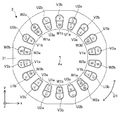
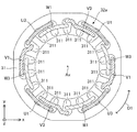
- FIG. It is a top view which shows schematic structure of the electric motor which concerns on Embodiment 1.
- FIG. It is sectional drawing which shows schematic structure of a rotor. It is a top view which shows the structure of a stator schematically. It is a figure which shows the arrangement of the three-phase coil in a slot. It is a figure which shows the arrangement of the three-phase coil in a coil end and a slot. It is a figure which shows the example of the position of the insulating member arranged in the coil end. It is a figure which shows another example of the position of the insulating member arranged at the coil end. It is a figure which shows the example of the position of the insulating member arranged in a slot.
- FIG. 1 It is a flowchart which shows an example of the manufacturing process of a stator. It is a figure which shows the example of the insertion instrument for inserting a three-phase coil into a stator core. It is a figure which shows the insertion process of the 3rd coil in step S11. It is a figure which shows the insertion process of the 2nd coil in step S12. It is a figure which shows the insertion process of the 1st coil in step S14. It is a top view which shows the electric motor which concerns on a comparative example. It is a figure which shows the arrangement of the three-phase coil in the slot of the stator shown in FIG. It is a top view which shows roughly the structure of the electric motor 1 which concerns on Embodiment 2.
- FIG. 1 which concerns on Embodiment 2.
- FIG. 1 shows schematic structure of the electric motor which concerns on Embodiment 3.
- FIG. It is a figure which shows the arrangement of the three-phase coil in a slot. It is a figure which shows the arrangement of the three-phase coil in a coil end and a slot.
- FIG. 1 It is a flowchart which shows an example of the manufacturing process of a stator. It is a figure which shows the insertion process of the 2nd coil in step S31. It is a figure which shows the insertion process of the 1st coil and the 3rd coil of the U-phase coil in step S32. It is a figure which shows the insertion process of the 1st coil and the 3rd coil of the V-phase coil in step S34. It is a figure which shows the insertion process of the 1st coil and the 3rd coil of the W phase coil in step S36. It is a top view which shows schematic structure of the electric motor which concerns on Embodiment 4. FIG. It is a figure which shows the arrangement of the three-phase coil in a coil end and a slot.
- FIG. 1 It is a flowchart which shows an example of the manufacturing process of a stator. It is a figure which shows the insertion process of the 1st coil and the 3rd coil of the U-phase coil in step S41. It is a figure which shows the insertion process of the 1st coil and the 3rd coil of the V-phase coil in step S43. It is a figure which shows the insertion process of the 1st coil and the 3rd coil of the W phase coil in step S45. It is a figure which shows the insertion process of the 2nd coil of the coil of each phase in step S46. It is a top view which shows schematic structure of the electric motor which concerns on Embodiment 5. FIG.
- FIG. 37 It is a top view which shows the electric motor corresponding to the electric motor shown in FIG. 37. It is a top view which shows schematic structure of the electric motor which concerns on Embodiment 6. It is a top view which shows the electric motor corresponding to the electric motor shown in FIG. 39. It is a top view which shows schematic structure of the electric motor which concerns on Embodiment 7.
- FIG. It is a top view which shows the electric motor corresponding to the electric motor shown in FIG. 41.
- FIG. 8 It is a top view which shows schematic structure of the electric motor which concerns on Embodiment 8.
- FIG. 43 It is sectional drawing which shows schematic structure of the compressor which concerns on Embodiment 9.
- FIG. It is a figure which shows schematic the structure of the refrigerating air-conditioning apparatus which concerns on Embodiment 10.
- Embodiment 1 In the xyz Cartesian coordinate system shown in each figure, the z-axis direction (z-axis) indicates a direction parallel to the axis Ax of the electric motor 1, and the x-axis direction (x-axis) is orthogonal to the z-axis direction (z-axis).
- the y-axis direction (y-axis) indicates a direction orthogonal to both the z-axis direction and the x-axis direction.
- the axis Ax is the center of the stator 3 and the center of rotation of the rotor 2.
- the direction parallel to the axis Ax is also referred to as "axial direction of rotor 2" or simply "axial direction”.
- the radial direction is the radial direction of the rotor 2 or the stator 3, is a direction orthogonal to the axis Ax, and is a direction away from the axis Ax.
- the xy plane is a plane orthogonal to the axial direction.
- the arrow D1 indicates the circumferential direction centered on the axis Ax.
- the circumferential direction of the rotor 2 or the stator 3 is also simply referred to as the "circumferential direction".
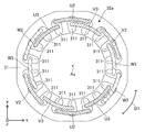
- FIG. 1 is a top view schematically showing the structure of the motor 1 according to the first embodiment.
- the motor 1 has a rotor 2 having a plurality of magnetic poles, a stator 3, and a shaft 4 fixed to the rotor 2.
- the electric motor 1 is, for example, a permanent magnet synchronous motor.
- the rotor 2 is rotatably arranged inside the stator 3. There is an air gap between the rotor 2 and the stator 3. The rotor 2 rotates about the axis Ax.
- FIG. 2 is a cross-sectional view schematically showing the structure of the rotor 2.
- the rotor 2 has a rotor core 21 and a plurality of permanent magnets 22.
- the rotor core 21 has a plurality of magnet insertion holes 211 and a shaft hole 212 in which the shaft 4 is arranged.
- the rotor core 21 may further have at least one flux barrier portion that is a space communicating with each magnet insertion hole 211.
- the rotor 2 has a plurality of permanent magnets 22.
- Each permanent magnet 22 is arranged in each magnet insertion hole 211.
- One permanent magnet 22 forms one magnetic pole of the rotor 2, that is, N pole or S pole. However, two or more permanent magnets 22 may form one magnetic pole of the rotor 2.
- one permanent magnet 22 forming one magnetic pole of the rotor 2 is arranged straight in the xy plane.
- a set of permanent magnets 22 forming one magnetic pole of the rotor 2 may be arranged so as to have a V shape.
- each magnetic pole of the rotor 2 is located at the center of each magnetic pole of the rotor 2 (that is, the north pole or the south pole of the rotor 2).
- Each magnetic pole of the rotor 2 (also simply referred to as “each magnetic pole” or “magnetic pole”) means a region serving as an north pole or an south pole of the rotor 2.
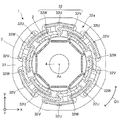
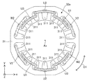
- FIG. 3 is a top view schematically showing the structure of the stator 3.
- FIG. 4 is a diagram showing the arrangement of the three-phase coil 32 in the slot 311.
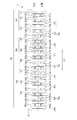
- FIG. 5 is a diagram showing the arrangement of the coil end 32a and the three-phase coil 32 in the slot 311.
- FIG. 5 is a developed view of the stator 3 shown in FIG. In FIG. 5, the dashed line indicates the coil of each phase at the coil end 32a, and the chain line indicates the boundary between the inner layer and the outer layer in each slot 311.
- the stator 3 has a stator core 31 and a three-phase coil 32 attached to the stator core 31 in a distributed winding manner.
- the three-phase coil 32 (that is, the coil of each phase) has a coil side arranged in the slot 311 and a coil end 32a not arranged in the slot 311. Each coil end 32a is an end of a three-phase coil 32 in the axial direction.
- the three-phase coil 32 has 3 ⁇ n U-phase coils 32U, 3 ⁇ n V-phase coils 32V, and 3 ⁇ n W-phase coils 32W at each coil end 32a (FIG. 1). That is, the three-phase coil 32 has three phases, a first phase, a second phase, and a third phase.
- the first phase is the U phase
- the second phase is the V phase
- the third phase is the W phase.
- each of the three phases is referred to as a U phase, a V phase, and a W phase.
- Each U-phase coil 32U, each V-phase coil 32V, and each W-phase coil 32W shown in FIG. 1 are also simply referred to as coils.
- n 2. Therefore, in the example shown in FIG. 1, at the coil end 32a, the three-phase coil 32 has six U-phase coils 32U, six V-phase coils 32V, and six W-phase coils 32W. However, the number of coils in each phase is not limited to six.
- the stator 3 has the structure shown in FIG. 3 at the two coil ends 32a. However, the stator 3 may have a structure shown in FIG. 3 at one of the two coil ends 32a.
- three U-phase coils 32U adjacent to each other in the circumferential direction at each coil end 32a are referred to as a first coil U1, a second coil U2, and a third coil U3, respectively.
- three V-phase coils 32V adjacent to each other in the circumferential direction at each coil end 32a are referred to as a first coil V1, a second coil V2, and a third coil V3, respectively.
- the three W-phase coils 32W adjacent to each other in the circumferential direction at each coil end 32a are referred to as a first coil W1, a second coil W2, and a third coil W3, respectively.
- Each first coil U1, each second coil U2, each third coil U3, each first coil V1, each second coil V2, each third coil V3, each first coil W1, each The second coil W2 and each third coil W3 are also simply referred to as coils.
- the six U-phase coils 32U are a group of two coils in which the first to third coils U1, U2, and U3 adjacent to each other in the circumferential direction at each coil end 32a are a set. Contains Ug.
- the six U-phase coils 32U include two sets of coil groups Ug, and each coil group Ug of the six U-phase coils 32U is a first coil adjacent in the circumferential direction at each coil end 32a.
- n sets of coil groups Ug out of 6 U-phase coils 32U are arranged at equal intervals in the circumferential direction of the stator 3.
- the first coil U1, the second coil U2, and the third coil U3 of each coil group Ug are arranged in this order in the circumferential direction of the stator 3 at a pitch of 2 slots. ..
- 2 slot pitch means "every 2 slots”. That is, the 2-slot pitch means that adjacent coils are arranged in slot 311 every two slots. In other words, the 2-slot pitch means that adjacent coils are arranged in slot 311 every other slot.
- the first coil U1, the second coil U2, and the third coil U3 of each coil group Ug are arranged in this order in the radial direction of the stator 3. ing.
- the first coil U1, the second coil U2, and the third coil U3 of each coil group Ug are arranged from the inside of the stator core 31 in the radial direction of the stator 3. They are arranged in this order.
- the first coil U1, the second coil U2, and the third coil U3 of each coil group Ug are connected in series.
- the second coil U2 of each coil group Ug is wound around the stator core 31 in the opposite direction to the other two coils U1 and U3.
- a part of the first coil U1 and a part of the second coil U2 in each coil group Ug are arranged in one slot 311 out of 18 slots 311.
- the other part of the second coil U2 and the part of the third coil U3 of each coil group Ug are arranged in the other slot 311 of the 18 slots 311. ..
- the other part of the first coil U1 of each coil group Ug is arranged in one slot 311 together with a part of the coils of the other phases.
- the other part of the third coil U3 of each coil group Ug is arranged in one slot 311 together with some of the coils of the other phase.
- a part of the first coil U1 is a first portion U1a of the first coil U1
- the other part of the first coil U1 is a first portion of the first coil U1.
- Part 2 U1b, part of the second coil U2 is the first part U2a of the second coil U2, and the other part of the second coil U2 is the second part of the second coil U2.
- Part U2b, part of the third coil U3 is the first part U3a of the third coil U3, and the other part of the third coil U3 is the second part U3b of the third coil U3.
- a part of the first coil U1 may be read as a second part U1b of the first coil U1, and the other part of the first coil U1 may be referred to as a first coil U1.
- the part U1a of 1 may be read
- a part of the second coil U2 may be read as the second part U2b of the second coil U2
- the other part of the second coil U2 may be read as the second part.
- It may be read as the first part U2a of the coil U2
- a part of the third coil U3 may be read as the second part U3b of the third coil U3, and another part of the third coil U3. May be read as the first portion U3a of the third coil U3.
- the six V-phase coils 32V are a group of two coils including the first to third coils V1, V2, and V3 that are adjacent to each other in the circumferential direction at each coil end 32a.
- the six V-phase coils 32V include two sets of coil groups Vg, and each coil group Vg of the six V-phase coils 32V is a first coil adjacent to each other in the circumferential direction at each coil end 32a.
- n sets of coil groups Vg out of the six V-phase coils 32V are arranged at equal intervals in the circumferential direction of the stator 3.
- the first coil V1, the second coil V2, and the third coil V3 of each coil group Vg are arranged in this order in the circumferential direction of the stator 3 at a pitch of 2 slots. ..
- the first coil V1, the second coil V2, and the third coil V3 of each coil group Vg are arranged in this order in the radial direction of the stator 3. ing.
- the first coil V1, the second coil V2, and the third coil V3 of each coil group Vg are from the inside of the stator core 31 in the radial direction of the stator 3. They are arranged in this order.
- the first coil V1, the second coil V2, and the third coil V3 of each coil group Vg are connected in series.
- the second coil V2 of each coil group Vg is wound around the stator core 31 in the opposite direction to the other two coils V1 and V3.
- a part of the first coil V1 and a part of the second coil V2 in each coil group Vg are arranged in one slot 311 out of 18 slots 311.
- the other part of the second coil V2 and the part of the third coil V3 of each coil group Vg are arranged in the other slot 311 of the 18 slots 311. ..
- the other part of the first coil V1 of each coil group Vg is arranged in one slot 311 together with a part of the coils of the other phases.
- the other part of the third coil V3 of each coil group Vg is arranged in one slot 311 together with some of the coils of the other phase.
- a part of the first coil V1 is a first part V1a of the first coil V1
- the other part of the first coil V1 is a first portion of the first coil V1.
- Part 2 V1b, part of the second coil V2 is the first part V2a of the second coil V2, and the other part of the second coil V2 is the second part of the second coil V2.
- Part V2b, part of the third coil V3 is the first part V3a of the third coil V3, and the other part of the third coil V3 is the second part V3b of the third coil V3. Is.
- a part of the first coil V1 may be read as a second part V1b of the first coil V1, and the other part of the first coil V1 may be referred to as a first coil V1.
- a part of the second coil V2 may be read as a second part V2b of the second coil V2, and the other part of the second coil V2 may be read as a second part V1a.
- It may be read as the first part V2a of the coil V2
- a part of the third coil V3 may be read as the second part V3b of the third coil V3, and another part of the third coil V3. May be read as the first portion V3a of the third coil V3.
- the six W-phase coils 32W are a group of two coils in which the first to third coils W1, W2, and W3 adjacent to each other in the circumferential direction at each coil end 32a are a set. Contains Wg.
- the six W-phase coils 32W include two sets of coil groups Wg, and each coil group Wg of the six W-phase coils 32W is a first coil adjacent to each other in the circumferential direction at each coil end 32a. Includes W1, a second coil W2, and a third coil W3.
- n sets of coil groups Wg out of the six W-phase coils 32W are arranged at equal intervals in the circumferential direction of the stator 3.
- the first coil W1, the second coil W2, and the third coil W3 of each coil group Wg are arranged in this order in the circumferential direction of the stator 3 at a pitch of 2 slots. ..
- the first coil W1, the second coil W2, and the third coil W3 of each coil group Wg are arranged in this order in the radial direction of the stator 3. ing.
- the first coil W1, the second coil W2, and the third coil W3 of each coil group Wg are from the inside of the stator core 31 in the radial direction of the stator 3. They are arranged in this order.
- the first coil W1, the second coil W2, and the third coil W3 of each coil group Wg are connected in series.
- the second coil W2 of each coil group Wg is wound around the stator core 31 in the opposite direction to the other two coils W1 and W3.
- a part of the first coil W1 and a part of the second coil W2 in each coil group Wg are arranged in one slot 311 out of 18 slots 311.
- the other part of the second coil W2 and the part of the third coil W3 of each coil group Wg are arranged in the other slot 311 of the 18 slots 311. ..
- the other part of the first coil W1 of each coil group Wg is arranged in one slot 311 together with a part of the coils of the other phases.
- the other part of the third coil W3 of each coil group Wg is arranged in one slot 311 together with some of the coils of the other phases.
- a part of the first coil W1 is a first part W1a of the first coil W1
- the other part of the first coil W1 is a first portion of the first coil W1.
- Part 2 W1b, part of the second coil W2 is the first part W2a of the second coil W2, and the other part of the second coil W2 is the second part of the second coil W2.
- Part W2b, part of the third coil W3 is the first part W3a of the third coil W3, and the other part of the third coil W3 is the second part W3b of the third coil W3.
- a part of the first coil W1 may be read as a second part W1b of the first coil W1, and the other part of the first coil W1 may be referred to as a first coil W1.
- the part W1a of 1 may be read
- a part of the second coil W2 may be read as the second part W2b of the second coil W2
- the other part of the second coil W2 may be read as the second part.
- It may be read as the first part W2a of the coil W2
- a part of the third coil W3 may be read as the second part W3b of the third coil W3, and another part of the third coil W3. May be read as the first portion W3a of the third coil W3.
- each of the 3 ⁇ n U-phase coils 32U, the 3 ⁇ n V-phase coils 32V, and the 3 ⁇ n W-phase coils 32W each includes a set of first to third coils. Includes n sets of coils. At each coil end 32a, n sets of coils are arranged at equal intervals in the circumferential direction of the stator 3. In each phase, one set of coils (also referred to as each coil group) is three coils arranged continuously in the circumferential direction. In other words, in each phase, a set of coils is three coils adjacent to each other in the circumferential direction.
- the first to third coils constituting each coil group are arranged in this order in the circumferential direction of the stator 3 at a 2-slot pitch.
- the first to third coils constituting each coil group are arranged in this order in the radial direction of the stator 3.
- At each coil end 32a at least two of the first to third coils of at least one phase are adjacent to each other in the radial direction.
- the first coil and the second coil of each phase are adjacent to each other in the radial direction
- the second coil and the third coil of each phase are radially adjacent to each other. Adjacent to each other.
- the region where the first to third coils of each of the n sets of coils are arranged is divided into an inner region, an intermediate region, and an outer region.
- the inner region is the region closest to the center of the stator core 31
- the outer region is the region farthest from the center of the stator core 31
- the intermediate region is the region between the inner region and the outer layer.
- the first coil is arranged inside the second coil in the radial direction
- the third coil is arranged outside the second coil in the radial direction.
- the second coil is arranged between the first coil and the third coil.
- the first coil of the coil of each phase of the three-phase coil 32 is arranged in the inner layer of the slot 311.
- the second coil of the coil of each phase of the three-phase coil 32 is arranged in the inner layer or the outer layer of the slot 311.
- the third coil of the coil of each phase of the three-phase coil 32 is arranged in the outer layer of the slot 311.
- the coils of each phase are arranged in the 6 outer layers of the slot 311 and in the 6 inner layers of the slot 311.
- each second coil of the U-phase coil 32U is arranged in the outer layer of the slot 311 in which the first coil of the U-phase coil 32U is arranged.
- the other part of each second coil of the U-phase coil 32U is arranged in the inner layer of the slot 311 in which the third coil of the U-phase coil 32U is arranged.
- each third coil of the U-phase coil 32U is arranged in the outer layer of the slot 311 in which the second coil of the U-phase coil 32U is arranged.
- the other part of each third coil of the U-phase coil 32U is arranged in the outer layer of the slot 311 in which the first coil of the V-phase coil 32V is arranged. Therefore, the other part of each third coil of the U-phase coil 32U is arranged in the slot 311 outside the first coil of the V-phase coil 32V in the radial direction.
- V-phase coil 32V in slot 311 The arrangement of the V-phase coil 32V in the slot 311 will be specifically described below. A part of each first coil of the V-phase coil 32V is arranged in the inner layer of the slot 311 in which the second coil of the V-phase coil 32V is arranged. The other part of each first coil of the V-phase coil 32V is arranged in the inner layer of the slot 311 in which the third coil of the U-phase coil 32U is arranged. Therefore, the other part of each first coil of the V-phase coil 32V is arranged inside the third coil of the U-phase coil 32U in the radial direction in the slot 311.
- each second coil of the V-phase coil 32V is arranged in the outer layer of the slot 311 in which the first coil of the V-phase coil 32V is arranged.
- the other part of each second coil of the V-phase coil 32V is arranged in the inner layer of the slot 311 in which the third coil of the V-phase coil 32V is arranged.
- each third coil of the V-phase coil 32V is arranged in the outer layer of the slot 311 in which the second coil of the V-phase coil 32V is arranged.
- the other part of each third coil of the V-phase coil 32V is arranged in the outer layer of the slot 311 in which the first coil of the W-phase coil 32W is arranged. Therefore, the other part of each third coil of the V-phase coil 32V is arranged in the slot 311 outside the first coil of the W-phase coil 32W in the radial direction.
- each second coil of the W-phase coil 32W is arranged in the outer layer of the slot 311 in which the first coil of the W-phase coil 32W is arranged.
- the other part of each second coil of the W-phase coil 32W is arranged in the inner layer of the slot 311 in which the third coil of the W-phase coil 32W is arranged.
- each third coil of the W-phase coil 32W is arranged in the outer layer of the slot 311 in which the second coil of the W-phase coil 32W is arranged.
- the other part of each third coil of the W-phase coil 32W is arranged in the outer layer of the slot 311 in which the first coil of the U-phase coil 32U is arranged. Therefore, the other part of each third coil of the W-phase coil 32W is arranged in the slot 311 outside the first coil of the U-phase coil 32U in the radial direction.
- the position of the first coil and the position of the third coil of each coil group may be interchanged with each other.
- the third coil, the second coil, and the first coil of each coil group are arranged in this order in the circumferential direction of the stator 3 at a pitch of 2 slots, and the stators are arranged. It is arranged in this order in the radial direction of 3.
- the winding coefficient kw in the electric motor 1 is obtained by (short winding coefficient kp) ⁇ (distributed winding coefficient kd).
- FIG. 6 is a diagram showing an example of the position of the insulating member 33 arranged at the coil end 32a.
- FIG. 7 is a diagram showing another example of the position of the insulating member 33 arranged at the coil end 32a.
- the stator 3 may have an insulating member 33 that insulates the coils of each phase of the three-phase coil 32.
- the insulating member 33 is, for example, insulating paper.
- the teeth of the stator core 31 are present between the two coils adjacent in the circumferential direction, the two coils adjacent in the circumferential direction are insulated from each other. ..
- the first coil U1 of the U-phase coil 32U and the first coil W1 of the W-phase coil 32W are insulated from each other.
- the insulating member 33 is arranged between the first coil and the second coil, and the insulating member is arranged between the second coil and the third coil. 33 are arranged.
- the cost of the insulating member 33 can be reduced, and the insulating member 33 can be efficiently arranged at the coil end 32a.
- the insulating member 33 is arranged between the phases adjacent to each other.
- an insulating member 33 is arranged between the U-phase coil 32U and the V-phase coil 32V
- an insulating member 33 is arranged between the U-phase coil 32U and the W-phase coil 32W
- the V-phase coil 32V is arranged.
- An insulating member 33 is arranged between the W-phase coil 32W and the W-phase coil 32W.
- FIG. 8 is a diagram showing an example of the position of the insulating member 33 arranged in the slot 311. As shown in FIG. 8, when coils of different phases are arranged in one slot 311, the insulating member 33 is arranged between the outer layer and the inner layer of the slot 311. As a result, coils of different phases arranged in one slot 311 are insulated from each other.
- the method for manufacturing the stator 3 is to arrange the first to third coils in this order in the circumferential direction in a distributed winding manner at a pitch of two slots at each coil end 32a, and at least one phase at each coil end 32a. This includes arranging the first to third coils so that at least two of the first to third coils are adjacent to each other in the radial direction.
- the method for manufacturing the stator 3 includes arranging two sets of coils at equal intervals in the circumferential direction of the stator 3 at the coil ends 32a of each phase.
- FIG. 9 is a flowchart showing an example of the manufacturing process of the stator 3.
- FIG. 10 is a diagram showing an example of an insertion device 9 for inserting the three-phase coil 32 into the stator core 31.
- FIG. 11 is a diagram showing an insertion step of the third coil in step S11.
- the third coil of each phase is attached to the stator core 31 prepared in advance by the insertion tool 9.
- the third coil of each phase is arranged in a distributed winding in the outer layer of the slot 311 of the stator core 31. That is, the third coil of the U-phase coil 32U, the third coil of the V-phase coil 32V, and the third coil of the W-phase coil 32W are arranged in the outer layer of the slot 311 by distributed winding.
- each third coil of the U-phase coil 32U is arranged in the outer layer of the slot 311 in which the second coil of the U-phase coil 32U is arranged.
- the other part of each third coil of the U-phase coil 32U is arranged in the outer layer of slot 311 in which the first coil of the V-phase coil 32V is arranged. Therefore, the other part of each third coil of the U-phase coil 32U is arranged in the slot 311 outside the first coil of the V-phase coil 32V in the radial direction.
- each third coil of the V-phase coil 32V is arranged in the outer layer of the slot 311 in which the second coil of the V-phase coil 32V is arranged.
- the other part of each third coil of the V-phase coil 32V is arranged in the outer layer of slot 311 in which the first coil of the W-phase coil 32W is arranged. Therefore, the other part of each third coil of the V-phase coil 32V is arranged in the slot 311 outside the first coil of the W-phase coil 32W in the radial direction.
- a part of each third coil of the W-phase coil 32W is arranged in the outer layer of slot 311 in which the second coil of the W-phase coil 32W is arranged.
- the other part of each third coil of the W-phase coil 32W is arranged in the outer layer of slot 311 in which the first coil of the U-phase coil 32U is arranged. Therefore, the other part of each third coil of the W-phase coil 32W is arranged in the slot 311 outside the first coil of the U-phase coil 32U in the radial direction.
- the coil When inserting the three-phase coil 32 into the stator core 31 with the insertion device 9 shown in FIG. 10, the coil is arranged between the blades 91 of the insertion device 9, and the blade 91 is inserted inside the stator core 31 together with the coil. .. The coil is then slid axially and placed in slot 311. In steps S12 and S14, which will be described later, the three-phase coil 32 is inserted into the stator core 31 in the same manner.
- FIG. 12 is a diagram showing an insertion step of the second coil in step S12.
- step S12 as shown in FIG. 12, the second coil of each phase is attached to the stator core 31 by the insertion tool 9. Specifically, the second coil of each phase is arranged in a distributed winding in the outer layer or the inner layer of the slot 311.
- each second coil of the U-phase coil 32U is arranged in the outer layer of slot 311 in which the first coil of the U-phase coil 32U is arranged.
- the other part of each second coil of the U-phase coil 32U is arranged in the inner layer of slot 311 in which the third coil of the U-phase coil 32U is arranged.
- each second coil of the V-phase coil 32V is arranged in the outer layer of the slot 311 in which the first coil of the V-phase coil 32V is arranged.
- the other part of each second coil of the V-phase coil 32V is arranged in the inner layer of slot 311 in which the third coil of the V-phase coil 32V is arranged.
- each second coil of the W-phase coil 32W is arranged in the outer layer of slot 311 in which the first coil of the W-phase coil 32W is arranged.
- the other part of each second coil of the W-phase coil 32W is arranged in the inner layer of slot 311 in which the third coil of the W-phase coil 32W is arranged.
- step S13 the insulating member 33 is arranged in the slot 311 so as to insulate the coils of each phase of the three-phase coil 32. For example, before each first coil is inserted into the stator core 31, the insulating member 33 is placed in slot 311 where the third coil is located.
- FIG. 13 is a diagram showing an insertion step of the first coil in step S14.
- the first coil of each phase is attached to the stator core 31 by the insertion tool 9.
- the first coil of each phase is arranged in a distributed winding in the inner layer of the slot 311. That is, the first coil of the U-phase coil 32U, the first coil of the V-phase coil 32V, and the first coil of the W-phase coil 32W are arranged in the inner layer of the slot 311 by distributed winding.
- each first coil of the U-phase coil 32U is arranged in the inner layer of the slot 311 in which the second coil of the U-phase coil 32U is arranged.
- the other part of each first coil of the U-phase coil 32U is arranged in the inner layer of slot 311 in which the third coil of the W-phase coil 32W is arranged. Therefore, the other part of each first coil of the U-phase coil 32U is arranged inside the third coil of the W-phase coil 32W in the radial direction in the slot 311.
- a part of each first coil of the V-phase coil 32V is arranged in the inner layer of the slot 311 in which the second coil of the V-phase coil 32V is arranged.
- the other part of each first coil of the V-phase coil 32V is arranged in the inner layer of the slot 311 in which the third coil of the W-phase coil 32W is arranged. Therefore, the other part of each first coil of the V-phase coil 32V is arranged inside the third coil of the W-phase coil 32W in the radial direction in the slot 311.
- a part of each first coil of the W-phase coil 32W is arranged in the inner layer of the slot 311 in which the second coil of the W-phase coil 32W is arranged.
- the other part of each first coil of the W-phase coil 32W is arranged in the inner layer of slot 311 in which the third coil of the V-phase coil 32V is arranged. Therefore, the other part of each first coil of the W-phase coil 32W is arranged inside the third coil of the V-phase coil 32V in the radial direction in the slot 311.
- the three-phase coil 32 is attached to the stator core 31 in a distributed winding manner so that the three-phase coil 32 has the above-mentioned arrangement at each coil end 32a and slot 311 of the three-phase coil 32.
- n sets of coil groups are arranged at equal intervals in the circumferential direction of the stator 3, and at the coil ends 32a of each phase, the first to first coil groups constituting each coil group are formed.
- the three-phase coil 32 is attached to the stator core 31 in a distributed winding manner so that the coils of 3 are arranged in this order in the circumferential direction of the stator 3 at a 2-slot pitch.
- the three-phase coils are arranged in this order from the inside of the stator core 31 in the radial direction of the stator 3 so that the first to third coils constituting each coil group are arranged in this order from the inside of the stator core 31.
- 32 is distributed and attached to the stator core 31.
- the three-phase coil 32 is located so that the second coil is located outside the first coil and the third coil is located outside the second coil. Is attached to the stator core 31.
- step S15 the U-phase coil 32U, the V-phase coil 32V, and the W-phase coil 32W are connected to each other.
- the U-phase coil 32U, the V-phase coil 32V, and the W-phase coil 32W are connected by Y connection or delta connection. Further, the shape of the connected three-phase coil 32 is adjusted. As a result, the stator 3 shown in FIG. 3 is obtained.
- FIG. 14 is a top view showing the motor 1a according to the comparative example.
- FIG. 15 is a diagram showing the arrangement of the three-phase coil 32 in the slot of the stator 3a shown in FIG.
- FIG. 15 is a developed view of the stator 3a shown in FIG.
- the three-phase coil 32 is lapped and attached to the stator core 31. In this case, at each coil end 32a, one side of each coil is arranged in the outer layer of slot 311 and the other side of the coil is arranged in the inner layer of the other slot 311.
- the three-phase coil 32 when the three-phase coil 32 is attached to the stator core 31 by lap winding, it is difficult to attach the three-phase coil 32 to the stator core 31 by using an insertion tool (for example, the insertion tool 9 shown in FIG. 10). .. Therefore, usually, when the three-phase coil 32 is attached to the stator core 31 by lap winding as in the comparative example, the three-phase coil 32 is attached to the stator core 31 by hand. In this case, the productivity of the stator 3 decreases.
- an insertion tool for example, the insertion tool 9 shown in FIG. 10
- stator 3 According to the stator 3 in the present embodiment, the balance of inductance in the three-phase coil 32 is improved. Therefore, it is possible to suppress an increase in torque ripple and an increase in loss in the motor 1 having the stator 3.
- At the coil end 32a at least two of the first to third coils of at least one phase are adjacent to each other in the radial direction. That is, coils of the same phase overlap in the radial direction. Therefore, the number of insulating members 33 for insulating the coils of each phase can be reduced.
- the stator 3 having the above-mentioned advantages can be manufactured. Further, according to the method for manufacturing the stator 3, the three-phase coil 32 can be attached to the stator core 31 by using the insertion tool 9. Therefore, for example, the stator 3 can be manufactured more efficiently than the stator 3a described as a comparative example.
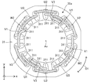
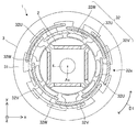
- FIG. 16 is a top view schematically showing the structure of the motor 1 according to the second embodiment.
- the arrangement of the three-phase coil 32 is different from the arrangement described in the first embodiment.
- a configuration different from that of the first embodiment will be described.
- the configuration not described in the present embodiment can be the same configuration as in the first embodiment.
- FIG. 17 is a diagram showing the arrangement of the coil end 32a and the three-phase coil 32 in the slot 311.
- FIG. 17 is a developed view of the stator 3 shown in FIG. In FIG. 17, the dashed line indicates the coil of each phase at the coil end 32a, and the chain line indicates the boundary between the inner layer and the outer layer in each slot 311.
- stator core 31 has 18 slots 311 as in the first embodiment.
- ⁇ Coil arrangement at coil end 32a> At each coil end 32a, n sets of coils are arranged at equal intervals in the circumferential direction of the stator 3. At the coil ends 32a of each phase, the first to third coils constituting each coil group are arranged in this order in the circumferential direction of the stator 3 at a pitch of 2 slots. At each coil end 32a, at least two of the first to third coils of at least one phase are radially adjacent to each other. In the present embodiment, at each coil end 32a, the second coil and the third coil of each phase are adjacent to each other in the radial direction.
- the second coil of the first to third coils constituting each coil group is arranged outside the first coil and the third coil in the radial direction of the stator 3.
- One of the first coil and the third coil is closer to the center of the stator core 31 than the other. That is, at the coil end 32a of each phase, one of the first coil and the third coil is closer to the axis Ax than the other. Specifically, at the coil end 32a of each phase, the first coil is closer to the center of the stator core 31 than the third coil.
- the first coil is arranged in the inner region, the second coil is arranged in the outer region, and the third coil is arranged in the intermediate region.
- the first coil is arranged inside the second coil in the radial direction, and the second coil is arranged outside the third coil in the radial direction.
- the third coil is arranged between the first coil and the second coil.
- Each third coil is arranged between the first coil of the other adjacent phase and the second coil of the other phase.
- the V-phase third coil is arranged between the U-phase first coil and the U-phase second coil. Therefore, at the coil end 32a of each coil group, the first coil is separated from the second coil.
- the first coil of the coil of each phase of the three-phase coil 32 is arranged in the inner layer of the slot 311.
- the second coil of the coil of each phase of the three-phase coil 32 is arranged in the outer layer of the slot 311.
- the third coil of the coil of each phase of the three-phase coil 32 is arranged in the inner layer or the outer layer of the slot 311.
- each first coil is arranged in the inner layer of slot 311 and each second coil is arranged in the outer layer of slot 311.
- One end of each third coil is arranged in the inner layer of the slot 311 and the other end is arranged in the outer layer of the other slot 311.
- the coils of each phase are arranged at 6 locations on the outer layer of slot 311 and at 6 locations on the inner layer of slot 311.
- each second coil of the U-phase coil 32U is arranged in the outer layer of the slot 311 in which the first coil of the U-phase coil 32U is arranged.
- the other part of each second coil of the U-phase coil 32U is arranged in the outer layer of slot 311 in which the third coil of the U-phase coil 32U is arranged.
- each third coil of the U-phase coil 32U is arranged in the inner layer of the slot 311 in which the second coil of the U-phase coil 32U is arranged.
- the other part of each third coil of the U-phase coil 32U is arranged in the outer layer of the slot 311 in which the first coil of the V-phase coil 32V is arranged. Therefore, the other part of each third coil of the U-phase coil 32U is arranged in the slot 311 outside the first coil of the V-phase coil 32V in the radial direction.
- V-phase coil 32V in slot 311 The arrangement of the V-phase coil 32V in the slot 311 will be specifically described below. A part of each first coil of the V-phase coil 32V is arranged in the inner layer of the slot 311 in which the second coil of the V-phase coil 32V is arranged. The other part of each first coil of the V-phase coil 32V is arranged in the inner layer of the slot 311 in which the third coil of the U-phase coil 32U is arranged. Therefore, the other part of each first coil of the V-phase coil 32V is arranged inside the third coil of the U-phase coil 32U in the radial direction in the slot 311.
- each second coil of the V-phase coil 32V is arranged in the outer layer of the slot 311 in which the first coil of the V-phase coil 32V is arranged.
- the other part of each second coil of the V-phase coil 32V is arranged in the outer layer of the slot 311 in which the third coil of the V-phase coil 32V is arranged.
- each third coil of the V-phase coil 32V is arranged in the inner layer of the slot 311 in which the second coil of the V-phase coil 32V is arranged.
- the other part of each third coil of the V-phase coil 32V is arranged in the outer layer of the slot 311 in which the first coil of the W-phase coil 32W is arranged. Therefore, the other part of each third coil of the V-phase coil 32V is arranged in the slot 311 outside the first coil of the W-phase coil 32W in the radial direction.
- each second coil of the W-phase coil 32W is arranged in the outer layer of the slot 311 in which the first coil of the W-phase coil 32W is arranged.
- the other part of each second coil of the W-phase coil 32W is arranged in the outer layer of the slot 311 in which the third coil of the W-phase coil 32W is arranged.
- each third coil of the W-phase coil 32W is arranged in the inner layer of the slot 311 in which the second coil of the W-phase coil 32W is arranged.
- the other part of each third coil of the W-phase coil 32W is arranged in the outer layer of the slot 311 in which the first coil of the U-phase coil 32U is arranged. Therefore, the other part of each third coil of the W-phase coil 32W is arranged in the slot 311 outside the first coil of the U-phase coil 32U in the radial direction.
- the insulating member 33 can be arranged in the same manner as in the first embodiment.
- the position of the first coil and the position of the third coil of each coil group may be interchanged with each other.
- the third coil, the second coil, and the first coil of each coil group are arranged in this order in the circumferential direction of the stator 3 at a pitch of 2 slots, and the first coil is arranged.
- the third coil is closer to the center of the stator core 31 than the coil of.
- the third coil is separated from the second coil.
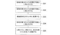
- FIG. 18 is a flowchart showing an example of the manufacturing process of the stator 3.
- FIG. 19 is a diagram showing an insertion step of the second coil in step S21.
- the second coil of each phase is attached to the stator core 31 prepared in advance by the insertion tool 9.
- the second coil of each phase is arranged in a distributed winding in the outer layer of the slot 311 of the stator core 31. That is, the second coil of the U-phase coil 32U, the second coil of the V-phase coil 32V, and the second coil of the W-phase coil 32W are arranged in the outer layer of the slot 311 by distributed winding.
- FIG. 20 is a diagram showing an insertion step of the third coil in step S22.
- step S22 as shown in FIG. 20, the third coil of each phase is attached to the stator core 31 by the insertion tool 9. Specifically, the third coil of each phase is arranged in a distributed winding in the outer layer or the inner layer of the slot 311.
- each third coil of the U-phase coil 32U is arranged in the inner layer of the slot 311 in which the second coil of the U-phase coil 32U is arranged.
- the other part of each third coil of the U-phase coil 32U is arranged in the outer layer of slot 311 in which the first coil of the V-phase coil 32V is arranged.
- each third coil of the V-phase coil 32V is arranged in the inner layer of the slot 311 in which the second coil of the V-phase coil 32V is arranged.
- the other part of each third coil of the V-phase coil 32V is arranged in the outer layer of slot 311 in which the first coil of the W-phase coil 32W is arranged.
- each third coil of the W-phase coil 32W is arranged in the inner layer of the slot 311 in which the second coil of the W-phase coil 32W is arranged.
- the other part of each third coil of the W-phase coil 32W is arranged in the outer layer of slot 311 in which the first coil of the U-phase coil 32U is arranged.
- the insulating member 33 is arranged in the slot 311 so as to insulate the coils of each phase of the three-phase coil 32.
- the insulating member 33 is placed in slot 311 where the third coil is located. In this case, since a part of the third coil and the second coil are arranged in the outer layer of the slot 311, it is easier to arrange the insulating member 33 in the slot 311 as compared with the first embodiment.
- FIG. 21 is a diagram showing an insertion step of the first coil in step S24.
- the first coil of each phase is attached to the stator core 31 by the insertion tool 9.
- the first coil of each phase is arranged in a distributed winding in the inner layer of the slot 311 of the stator core 31. That is, the first coil of the U-phase coil 32U, the first coil of the V-phase coil 32V, and the first coil of the W-phase coil 32W are arranged in the inner layer of the slot 311 by distributed winding.
- each first coil of the U-phase coil 32U is arranged in the inner layer of the slot 311 in which the second coil of the U-phase coil 32U is arranged.
- the other part of each first coil of the U-phase coil 32U is arranged in the inner layer of slot 311 in which the third coil of the W-phase coil 32W is arranged.
- a part of each first coil of the V-phase coil 32V is arranged in the inner layer of the slot 311 in which the second coil of the V-phase coil 32V is arranged.
- the other part of each first coil of the V-phase coil 32V is arranged in the inner layer of slot 311 in which the third coil of the U-phase coil 32U is arranged.
- a part of each first coil of the W-phase coil 32W is arranged in the inner layer of the slot 311 in which the second coil of the W-phase coil 32W is arranged.
- the other part of each first coil of the W-phase coil 32W is arranged in the inner layer of slot 311 in which the third coil of the V-phase coil 32V is arranged.
- the three-phase coil 32 is attached to the stator core 31 in a distributed winding so that the three-phase coil 32 has the above-mentioned arrangement at each coil end 32a and slot 311 of the three-phase coil 32.
- n sets of coil groups are arranged at equal intervals in the circumferential direction of the stator 3, and at the coil ends 32a of each phase, the first to first coil groups constituting each coil group are formed.
- the three-phase coil 32 is attached to the stator core 31 in a distributed winding manner so that the coils of 3 are arranged in this order in the circumferential direction of the stator 3 at a 2-slot pitch.
- the first coil, the third coil, and the second coil constituting each coil group are arranged in this order from the inside of the stator core 31 in the radial direction of the stator 3.
- the three-phase coil 32 is attached to the stator core 31 in a distributed winding so as to be performed.
- the second coil is arranged outside the first coil and the third coil in the radial direction of the stator 3, and the first coil and the third coil are arranged.
- the three-phase coil 32 is attached to the stator core 31 so that one is closer to the center of the stator core 31 than the other.
- step S25 the U-phase coil 32U, the V-phase coil 32V, and the W-phase coil 32W are connected to each other.
- the U-phase coil 32U, the V-phase coil 32V, and the W-phase coil 32W are connected by Y connection or delta connection. Further, the shape of the connected three-phase coil 32 is adjusted. As a result, the stator 3 shown in FIG. 16 is obtained.
- stator 3 According to the stator 3 in the present embodiment, the balance of inductance in the three-phase coil 32 is improved. Therefore, it is possible to suppress an increase in torque ripple and an increase in loss in the motor 1 having the stator 3.
- At the coil end 32a at least two of the first to third coils of at least one phase are adjacent to each other in the radial direction. Specifically, coils of the same phase partially overlap in the radial direction. Therefore, the number of insulating members 33 for insulating the coils of each phase can be reduced.
- the stator 3 having the above-mentioned advantages can be manufactured. Further, according to the method for manufacturing the stator 3, the three-phase coil 32 can be attached to the stator core 31 by using the insertion tool 9. Therefore, for example, the stator 3 can be manufactured more efficiently than the stator 3a described as a comparative example.
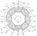
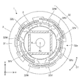
- FIG. 22 is a top view schematically showing the structure of the motor 1 according to the third embodiment.
- the arrangement of the three-phase coil 32 is different from the arrangement described in the first embodiment.
- a configuration different from that of the first embodiment will be described.
- the configuration not described in the present embodiment can be the same configuration as in the first embodiment.
- FIG. 23 is a diagram showing the arrangement of the three-phase coil 32 in the slot 311.
- FIG. 24 is a diagram showing the arrangement of the coil end 32a and the three-phase coil 32 in the slot 311.
- FIG. 24 is a developed view of the stator 3 shown in FIG. 23.
- the dashed line indicates the coil of each phase at the coil end 32a
- the chain line indicates the boundary between the inner layer and the outer layer in each slot 311.
- the stator core 31 has 18 slots 311 as in the first embodiment.
- ⁇ Coil arrangement at coil end 32a> At each coil end 32a, n sets of coils are arranged at equal intervals in the circumferential direction of the stator 3.
- the first to third coils constituting each coil group are arranged in this order in the circumferential direction of the stator 3 at a pitch of 2 slots.
- At each coil end 32a, at least two of the first to third coils of at least one phase are radially adjacent to each other.
- the first coil and the second coil of the U phase are adjacent to each other in the radial direction, and the second coil and the third coil of the U phase are radially adjacent to each other.
- the first coil and the second coil of the V phase are adjacent to each other in the radial direction.
- the second coil of the first to third coils constituting each coil group is arranged outside the first coil and the third coil in the radial direction of the stator 3. Has been done.
- the first coil and the third coil of the W-phase coil 32W are closest to the center of the stator core 31 among the three-phase coils 32.
- each first coil and each third coil of the U-phase coil 32U are arranged in an intermediate region, and each second coil of the U-phase coil 32U. Is located in the outer region.
- a portion of each first coil of the V-phase coil 32V is located in the inner region and the other portion of each first coil of the V-phase coil 32V is located in the intermediate region.
- the second coil of the V-phase coil 32V is arranged in the outer region, and a part of each third coil of the V-phase coil 32V is arranged in the inner region.
- the other part of each third coil of 32V is located in the intermediate region.
- each first coil and each third coil of the W-phase coil 32W are arranged in the inner region, and each second coil of the W-phase coil 32W is arranged in the outer region.
- Each second coil of each phase is located in the outer layer of slot 311.
- a part of the first coil of the U-phase coil 32U is arranged in the inner layer of the slot 311 and the other part of the first coil of the U-phase coil 32U is arranged in the outer layer of the other slot 311. There is. A part of the third coil of the U-phase coil 32U is arranged in the inner layer of the slot 311 and the other part of the third coil of the U-phase coil 32U is arranged in the outer layer of the other slot 311. There is.
- the first coil of the V-phase coil 32V is arranged in the inner layer of slot 311.
- a part of the third coil of the V-phase coil 32V is arranged in the inner layer of the slot 311 and the other part of the third coil of the V-phase coil 32V is arranged in the outer layer of the other slot 311. There is.
- the first coil and the third coil of the W-phase coil 32W are arranged in the inner layer of the slot 311.
- Each second coil of the U-phase coil 32U is arranged in the outer layer of slot 311.
- each third coil of the U-phase coil 32U is arranged in the inner layer of the slot 311 in which the second coil of the U-phase coil 32U is arranged.
- the other part of each third coil of the U-phase coil 32U is arranged in the outer layer of the slot 311 in which the first coil of the V-phase coil 32V is arranged. Therefore, the other part of each third coil of the U-phase coil 32U is arranged in the slot 311 outside the first coil of the V-phase coil 32V in the radial direction.
- Each first coil of the V-phase coil 32V is arranged in the inner layer of slot 311. Specifically, a part of each first coil of the V-phase coil 32V is arranged in the inner layer of the slot 311 in which the second coil of the V-phase coil 32V is arranged. The other part of each first coil of the V-phase coil 32V is arranged in the inner layer of the slot 311 in which the third coil of the U-phase coil 32U is arranged. Therefore, the other part of each first coil of the V-phase coil 32V is a third coil of the U-phase coil 32U in the radial direction in the slot 311 in which the third coil of the U-phase coil 32U is arranged. It is located inside.
- Each second coil of the V-phase coil 32V is arranged in the outer layer of slot 311.
- a part of each third coil of the V-phase coil 32V is arranged in the inner layer of the slot 311, and the other part of each third coil of the V-phase coil 32V is the other slot 311. It is placed in the outer layer of. Specifically, a part of each third coil of the V-phase coil 32V is arranged in the inner layer of the slot 311 in which the second coil of the V-phase coil 32V is arranged, and the V-phase coil 32V The other part of each of the third coils is arranged in the outer layer of the slot 311 in which the first coil of the W-phase coil 32W is arranged. Therefore, the other part of each third coil of the V-phase coil 32V is arranged in the slot 311 outside the first coil of the W-phase coil 32W in the radial direction.
- Each second coil of the W-phase coil 32W is arranged in the outer layer of slot 311.
- each third coil of the W-phase coil 32W is arranged in the inner layer of the slot 311 in which the second coil of the W-phase coil 32W is arranged. Therefore, a part of each third coil of the W-phase coil 32W is a part of the second coil of the W-phase coil 32W in the radial direction in the slot 311 in which the second coil of the W-phase coil 32W is arranged. It is located inside. The other part of each third coil of the W-phase coil 32W is arranged in the inner layer of the slot 311 in which the first coil of the U-phase coil 32U is arranged.
- each third coil of the W-phase coil 32W is a part of the first coil of the U-phase coil 32U in the radial direction in the slot 311 in which the first coil of the U-phase coil 32U is arranged. It is located inside.
- the insulating member 33 can be arranged in the same manner as in the first embodiment.
- the position of the first coil and the position of the third coil of each coil group may be interchanged with each other.
- the third coil, the second coil, and the first coil of each coil group are arranged in this order in the circumferential direction of the stator 3 at a pitch of 2 slots.
- the second coil of the first to third coils constituting each coil group is arranged outside the first coil and the third coil in the radial direction of the stator 3.
- FIG. 25 is a flowchart showing an example of the manufacturing process of the stator 3.
- FIG. 26 is a diagram showing an insertion step of the second coil in step S31.
- the second coil of each phase is attached to the stator core 31 prepared in advance by the insertion tool 9.
- the second coil of each phase is arranged in a distributed winding on the outer layer of the slot 311. That is, the second coil of the U-phase coil 32U, the second coil of the V-phase coil 32V, and the second coil of the W-phase coil 32W are arranged in the outer layer of the slot 311 by distributed winding.
- FIG. 27 is a diagram showing an insertion step of the first coil and the third coil of the U-phase coil 32U in step S32.
- step S32 as shown in FIG. 27, the first coil and the third coil of the U-phase coil 32U are attached to the stator core 31 by the insertion tool 9.
- the first coil and the third coil of the U-phase coil 32U are arranged in a distributed winding in the outer layer or the inner layer of the slot 311.
- each first coil of the U-phase coil 32U is arranged in the inner layer of the slot 311 in which the second coil of the U-phase coil 32U is arranged.
- the other part of each first coil of the U-phase coil 32U is arranged in the outer layer of slot 311 in which the third coil of the W-phase coil is arranged.
- each third coil of the U-phase coil 32U is arranged in the inner layer of the slot 311 in which the second coil of the U-phase coil 32U is arranged.
- the other part of each third coil of the U-phase coil 32U is arranged in the outer layer of slot 311 in which the first coil of the V-phase coil 32V is arranged.
- step S33 the insulating member 33 is arranged in the slot 311 so as to insulate the coils of each phase of the three-phase coil 32.
- the insulating members 33 are arranged at four positions of the stator core 31 so that the first coil and the third coil of the U-phase coil 32U are insulated.
- FIG. 28 is a diagram showing an insertion step of the first coil and the third coil of the V-phase coil 32V in step S34.
- step S24 as shown in FIG. 28, the first coil and the third coil of the V-phase coil 32V are attached to the stator core 31 by the insertion tool 9.
- the first coil and the third coil of the V-phase coil 32V are arranged in a distributed winding in the outer layer or the inner layer of the slot 311.
- each first coil of the V-phase coil 32V is arranged in the inner layer of the slot 311 in which the second coil of the V-phase coil 32V is arranged.
- the other part of each first coil of the V-phase coil 32V is arranged in the inner layer of slot 311 in which the third coil of the U-phase coil 32U is arranged.
- a part of each third coil of the V-phase coil 32V is arranged in the inner layer of the slot 311 in which the second coil of the V-phase coil 32V is arranged.
- the other part of each third coil of the V-phase coil 32V is arranged in the outer layer of slot 311 in which the first coil of the W-phase coil 32W is arranged.
- step S35 the insulating member 33 is arranged in the slot 311 so as to insulate the V-phase coil 32V of the three-phase coil 32. Specifically, in the slot 311 in which the other part of the third coil of the V-phase coil 32V is arranged, the insulating member 33 is arranged inside the third coil.
- FIG. 29 is a diagram showing an insertion step of the first coil and the third coil of the W phase coil 32W in step S36.
- step S36 as shown in FIG. 29, the first coil and the third coil of the W-phase coil 32W are attached to the stator core 31 by the insertion tool 9. Specifically, the first coil and the third coil of the W-phase coil 32W are arranged in a distributed winding in the inner layer of the slot 311.
- each first coil of the W-phase coil 32W is arranged in the inner layer of the slot 311 in which the second coil of the W-phase coil 32W is arranged.
- the other part of each first coil of the W-phase coil 32W is arranged in the inner layer of slot 311 in which the third coil of the V-phase coil 32V is arranged.
- a part of each third coil of the W-phase coil 32W is arranged in the inner layer of the slot 311 in which the second coil of the W-phase coil 32W is arranged.
- the other part of each third coil of the W-phase coil 32W is arranged in the inner layer of slot 311 in which the first coil of the U-phase coil 32U is arranged.
- the three-phase coil 32 is attached to the stator core 31 in a distributed winding so that the three-phase coil 32 has the above-mentioned arrangement at each coil end 32a and slot 311 of the three-phase coil 32.
- n sets of coil groups are arranged at equal intervals in the circumferential direction of the stator 3, and at the coil ends 32a of each phase, the first to first coil groups constituting each coil group are formed.
- the coil 3 is attached to the stator core 31 in a distributed winding manner with the three-phase coil 32 arranged in this order in the circumferential direction of the stator 3 at a 2-slot pitch.
- the second coil of the first to third coils constituting each coil group is of the first coil and the third coil in the radial direction of the stator 3. It is arranged on the outside, and at each coil end 32a, the first coil and the third coil of the W-phase coil 32W are arranged closest to the center of the stator core 31 among the three-phase coils 32.
- step S37 the U-phase coil 32U, the V-phase coil 32V, and the W-phase coil 32W are connected to each other.
- the U-phase coil 32U, the V-phase coil 32V, and the W-phase coil 32W are connected by Y connection or delta connection. Further, the shape of the connected three-phase coil 32 is adjusted. As a result, the stator 3 shown in FIG. 22 is obtained.
- stator 3 According to the stator 3 in the present embodiment, the balance of inductance in the three-phase coil 32 is improved. Therefore, it is possible to suppress an increase in torque ripple and an increase in loss in the motor 1 having the stator 3.
- At the coil end 32a at least two of the first to third coils of at least one phase are adjacent to each other in the radial direction. Specifically, coils of the same phase partially overlap in the radial direction. Therefore, the number of insulating members 33 for insulating the coils of each phase can be reduced.
- the stator 3 having the above-mentioned advantages can be manufactured. Further, according to the method for manufacturing the stator 3, the three-phase coil 32 can be attached to the stator core 31 by using the insertion tool 9. Therefore, for example, the stator 3 can be manufactured more efficiently than the stator 3a described as a comparative example.
- the coils of each phase can be attached to the stator core 31 in a state where the first coil and the third coil of each coil group of each phase are connected in series. can. Therefore, it is not necessary to connect the first coil and the third coil after arranging the coils of each phase in the slot 311.
- steps S32, S34, and S36 four coils are simultaneously arranged at each coil end 32a. Therefore, with two coils of each coil group installed in the insertion tool 9, these two coils can be connected to each other, and the connected coil is attached to the stator core 31 by the insertion tool 9. Can be done. Therefore, it is possible to reduce the wiring work after attaching the three-phase coil 32 to the stator core 31.
- FIG. 30 is a top view schematically showing the structure of the motor 1 according to the fourth embodiment.
- the arrangement of the three-phase coil 32 is different from the arrangement described in the first embodiment.
- a configuration different from that of the first embodiment will be described.
- the configuration not described in the present embodiment can be the same configuration as in the first embodiment.
- FIG. 31 is a diagram showing the arrangement of the coil end 32a and the three-phase coil 32 in the slot 311.
- FIG. 31 is a developed view of the stator 3 shown in FIG. In FIG. 31, the dashed line indicates the coil of each phase at the coil end 32a, and the chain line indicates the boundary between the inner layer and the outer layer in each slot 311.
- the stator core 31 has 18 slots 311 as in the first embodiment.
- n sets of coils are arranged at equal intervals in the circumferential direction of the stator 3.
- the first to third coils constituting each coil group are arranged in this order in the circumferential direction of the stator 3 at a pitch of 2 slots.
- At each coil end 32a, at least two of the first to third coils of at least one phase are radially adjacent to each other.
- the first coil and the second coil of the W phase are adjacent to each other in the radial direction, and the second coil and the third coil of the W phase are radially adjacent to each other.
- the second coil and the third coil of the V phase are adjacent to each other in the radial direction.
- the second coil of the first to third coils constituting each coil group is arranged inside the first coil and the third coil in the radial direction of the stator 3. Has been done.
- the first coil and the third coil of the U-phase coil 32U are the farthest from the center of the stator core 31 among the three-phase coils 32.
- each first coil and each third coil of the U-phase coil 32U are arranged in the outer region, and each second coil of the U-phase coil 32U. Is located in the inner region.
- a portion of each first coil of the V-phase coil 32V is located in the intermediate region and the other portion of each first coil of the V-phase coil 32V is located in the outer region.
- each second coil of the V-phase coil 32V is located in the inner region.
- a portion of each third coil of the V-phase coil 32V is located in the intermediate region and the other portion of each first coil of the V-phase coil 32V is located in the outer region.
- each first coil and each third coil of the W-phase coil 32W are arranged in the intermediate region, and each second coil of the W-phase coil 32W is arranged in the inner region.
- Each second coil of each phase is located in the inner layer of slot 311.
- the first coil and the third coil of the U-phase coil 32U are arranged in the outer layer of slot 311.
- a part of the first coil of the V-phase coil 32V is arranged in the inner layer or the outer layer of the slot 311.
- the third coil of the V-phase coil 32V is arranged in the outer layer of the slot 311.
- the first coil and the third coil of the W-phase coil 32W are arranged in the inner layer or the outer layer of the slot 311.
- Each second coil of the U-phase coil 32U is arranged in the inner layer of slot 311.
- each third coil of the U-phase coil 32U is arranged in the outer layer of the slot 311 in which the second coil of the U-phase coil 32U is arranged.
- the other part of each third coil of the U-phase coil 32U is arranged in the outer layer of the slot 311 in which the first coil of the V-phase coil 32V is arranged. Therefore, the other part of each third coil of the U-phase coil 32U is arranged in the slot 311 outside the first coil of the V-phase coil 32V in the radial direction.
- V-phase coil 32V in slot 311 The arrangement of the V-phase coil 32V in the slot 311 will be specifically described below. A part of each first coil of the V-phase coil 32V is arranged in the outer layer of the slot 311 in which the second coil of the V-phase coil 32V is arranged. The other part of each first coil of the V-phase coil 32V is arranged in the inner layer of the slot 311 in which the third coil of the U-phase coil 32U is arranged. Therefore, the other part of each first coil of the V-phase coil 32V is the third of the U-phase coil 32U in the radial direction in the slot 311 in which the third coil of the U-phase coil 32U is arranged. It is located inside the coil.
- Each second coil of the V-phase coil 32V is arranged in the inner layer of slot 311.
- each third coil of the V-phase coil 32V is arranged in the outer layer of the slot 311 in which the second coil of the V-phase coil 32V is arranged.
- the other part of each third coil of the V-phase coil 32V is arranged in the outer layer of the slot 311 in which the first coil of the W-phase coil 32W is arranged. Therefore, the other part of each third coil of the V-phase coil 32V is the first of the W-phase coils 32W in the radial direction in the slot 311 in which the first coil of the W-phase coils 32W is arranged. It is located on the outside of the coil.
- each first coil of the W-phase coil 32W is arranged in the outer layer of the slot 311 in which the second coil of the W-phase coil 32W is arranged. Therefore, a part of each first coil of the W-phase coil 32W is a part of the second coil of the W-phase coil 32W in the radial direction in the slot 311 in which the second coil of the W-phase coil 32W is arranged. It is located on the outside. The other part of each first coil of the W-phase coil 32W is arranged in the inner layer of the slot 311 in which the third coil of the V-phase coil 32V is arranged.
- each first coil of the W-phase coil 32W is the third of the V-phase coil 32V in the radial direction in the slot 311 in which the third coil of the V-phase coil 32V is arranged. It is arranged inside the coil of 3.
- Each second coil of the W-phase coil 32W is arranged in the inner layer of slot 311.
- each third coil of the W-phase coil 32W is arranged in the inner layer of the slot 311 in which the first coil of the U-phase coil 32U is arranged. Therefore, a part of each third coil of the W-phase coil 32W is the first of the U-phase coils 32U in the radial direction in the slot 311 in which the first coil of the U-phase coil 32U is arranged. It is located inside the coil. The other part of each third coil of the W-phase coil 32W is arranged in the outer layer of the slot 311 in which the second coil of the W-phase coil 32W is arranged.
- each third coil of the W-phase coil 32W is the second portion of the W-phase coil 32W in the radial direction in the slot 311 in which the second coil of the W-phase coil 32W is arranged. It is located on the outside of the coil.
- the insulating member 33 can be arranged in the same manner as in the first embodiment.
- the position of the first coil and the position of the third coil of each coil group may be interchanged with each other.
- the third coil, the second coil, and the first coil of each coil group are arranged in this order in the circumferential direction of the stator 3 at a pitch of 2 slots.
- the second coil of the first to third coils constituting each coil group is arranged inside the first coil and the third coil in the radial direction of the stator 3.
- FIG. 32 is a flowchart showing an example of the manufacturing process of the stator 3.
- FIG. 33 is a diagram showing an insertion step of the first coil and the third coil of the U-phase coil 32U in step S41.
- step S41 as shown in FIG. 33, the first coil and the third coil of the U-phase coil 32U are attached to the stator core 31 prepared in advance by the insertion tool 9. Specifically, the first coil and the third coil of the U-phase coil 32U are arranged in a distributed winding on the outer layer of the slot 311.
- the insulating member 33 is arranged in the slot 311 so as to insulate the coils of each phase of the three-phase coil 32.
- the insulating members 33 are arranged at four positions of the stator core 31 so that the first coil and the third coil of the U-phase coil 32U are insulated.
- FIG. 34 is a diagram showing an insertion step of the first coil and the third coil of the V-phase coil 32V in step S43.
- step S43 as shown in FIG. 34, the first coil and the third coil of the V-phase coil 32V are attached to the stator core 31 prepared in advance by the insertion tool 9. Specifically, the first coil and the third coil of the V-phase coil 32V are arranged in a distributed winding in the outer layer or the inner layer of the slot 311.
- each first coil of the V-phase coil 32V is arranged in the outer layer of slot 311.
- the other part of each first coil of the V-phase coil 32V is arranged in the inner layer of the slot 311 in which the third coil of the U-phase coil 32U is arranged. Therefore, the other part of each first coil of the V-phase coil 32V is the third of the U-phase coils 32U in the radial direction in the slot 311 in which the third coil of the U-phase coils 32U is arranged. It is arranged inside the coil of 3.
- a part of each third coil of the V-phase coil 32V is arranged in the outer layer of the slot 311.
- the other part of each third coil of the V-phase coil 32V is also arranged in the outer layer of slot 311.
- the insulating member 33 is arranged in the slot 311 so as to insulate the coils of each phase of the three-phase coil 32.
- the insulating members 33 are arranged at four positions of the stator core 31 so that the coil group is insulated.
- FIG. 35 is a diagram showing an insertion step of the first coil and the third coil of the W phase coil 32W in step S45.
- step S45 as shown in FIG. 35, the first coil and the third coil of the W-phase coil 32W are attached to the stator core 31 prepared in advance by the insertion tool 9. Specifically, the first coil and the third coil of the W-phase coil 32W are inserted into the inner layer or the outer layer of the slot 311 of the stator core 31 in a distributed winding manner.
- each first coil of the W-phase coil 32W is arranged in the outer layer of slot 311 in which the second coil of the W-phase coil 32W is arranged.
- the other part of each first coil of the W-phase coil 32W is arranged in the inner layer of slot 311 in which the third coil of the V-phase coil 32V is arranged.
- a part of each third coil of the W-phase coil 32W is arranged in the outer layer of the slot 311 in which the second coil of the W-phase coil 32W is arranged.
- the other part of each third coil of the W-phase coil 32W is arranged in the inner layer of slot 311 in which the first coil of the U-phase coil 32U is arranged.
- FIG. 36 is a diagram showing a step of inserting the second coil of the coil of each phase in step S46.
- step S46 as shown in FIG. 36, the second coil of the coil of each phase is attached to the stator core 31 prepared in advance by the insertion tool 9. Specifically, the second coil of each phase is arranged in a distributed winding in the inner layer of the slot 311. That is, the second coil of the U-phase coil 32U, the second coil of the V-phase coil 32V, and the second coil of the W-phase coil 32W are arranged in a distributed winding in the inner layer of the slot 311.
- steps S41 to S46 the three-phase coil 32 is attached to the stator core 31 in a distributed winding so that the three-phase coil 32 has the above-mentioned arrangement at each coil end 32a and slot 311 of the three-phase coil 32.
- n sets of coil groups are arranged at equal intervals in the circumferential direction of the stator 3, and at the coil ends 32a of each phase, the first to first coil groups constituting each coil group are formed.
- the coil 3 is attached to the stator core 31 in a distributed winding manner with the three-phase coil 32 arranged in this order in the circumferential direction of the stator 3 at a 2-slot pitch.
- the second coil of the first to third coils constituting each coil group is of the first coil and the third coil in the radial direction of the stator 3.
- the first and third coils of the U-phase coil 32U are farthest from the center of the stator core 31 of the three-phase coils 32.
- step S47 the U-phase coil 32U, the V-phase coil 32V, and the W-phase coil 32W are connected to each other.
- the U-phase coil 32U, the V-phase coil 32V, and the W-phase coil 32W are connected by Y connection or delta connection. Further, the shape of the connected three-phase coil 32 is adjusted. As a result, the stator 3 shown in FIG. 30 is obtained.
- stator 3 According to the stator 3 in the present embodiment, the balance of inductance in the three-phase coil 32 is improved. Therefore, it is possible to suppress an increase in torque ripple and an increase in loss in the motor 1 having the stator 3.
- At the coil end 32a at least two of the first to third coils of at least one phase are adjacent to each other in the radial direction. Specifically, coils of the same phase partially overlap in the radial direction. Therefore, the number of insulating members 33 for insulating the coils of each phase can be reduced.
- the stator 3 having the above-mentioned advantages can be manufactured. Further, according to the method for manufacturing the stator 3, the three-phase coil 32 can be attached to the stator core 31 by using the insertion tool 9. Therefore, for example, the stator 3 can be manufactured more efficiently than the stator 3a described as a comparative example.
- the coils of each phase can be attached to the stator core 31 in a state where the first coil and the third coil of each coil group of each phase are connected in series. can. Therefore, it is not necessary to connect the first coil and the third coil after arranging the coils of each phase in the slot 311.
- steps S41, S43, and S45 four coils are simultaneously arranged at each coil end 32a. Therefore, with two coils of each coil group installed in the insertion tool 9, these two coils can be connected to each other, and the connected coil is attached to the stator core 31 by the insertion tool 9. Can be done. Therefore, it is possible to reduce the wiring work after attaching the three-phase coil 32 to the stator core 31.
- FIG. 37 is a top view schematically showing the structure of the motor 1 according to the fifth embodiment.
- the value of "n” is different from the value of "n” described in the first embodiment.
- n 1.
- a configuration different from that of the first embodiment will be described. The details not described in the present embodiment can be the same as those in the first embodiment.
- the three-phase coil 32 (that is, the coil of each phase) has a coil side arranged in the slot 311 and a coil end 32a not arranged in the slot 311. Each coil end 32a is an end of a three-phase coil 32 in the axial direction.
- the three-phase coil 32 has 3 ⁇ n U-phase coils 32U, 3 ⁇ n V-phase coils 32V, and 3 ⁇ n W-phase coils 32W at each coil end 32a (FIG. 1). That is, the three-phase coil 32 has three phases, a first phase, a second phase, and a third phase.
- the first phase is the U phase
- the second phase is the V phase
- the third phase is the W phase.
- each of the three phases is referred to as a U phase, a V phase, and a W phase.
- Each U-phase coil 32U, each V-phase coil 32V, and each W-phase coil 32W shown in FIG. 1 are also simply referred to as coils.
- the three-phase coil 32 has three U-phase coils 32U, three V-phase coils 32V, and three W-phase coils 32W.
- FIG. 38 is a top view showing the motor 1 corresponding to the motor 1 shown in FIG. 37.
- the three U-phase coils 32U adjacent to each other in the circumferential direction at each coil end 32a are referred to as a first coil U1, a second coil U2, and a third coil U3, respectively.
- the three V-phase coils 32V adjacent to each other in the circumferential direction at each coil end 32a are referred to as a first coil V1, a second coil V2, and a third coil V3, respectively.
- FIG. 38 the three U-phase coils 32V adjacent to each other in the circumferential direction at each coil end 32a are referred to as a first coil V1, a second coil V2, and a third coil V3, respectively.
- each W-phase coil 32W adjacent to each other in the circumferential direction at each coil end 32a are referred to as a first coil W1, a second coil W2, and a third coil W3, respectively.
- Each first coil U1, each second coil U2, each third coil U3, each first coil V1, each second coil V2, each third coil V3, each first coil W1, each The second coil W2 and each third coil W3 are also simply referred to as coils.
- the 3 ⁇ n U-phase coils 32U include a set of first to third coils U1, U2, and U3 adjacent to each other in the circumferential direction at each coil end 32a. Includes a set of coils.
- the 3 ⁇ n U-phase coils 32U include n sets of coils, and each coil group of the 3 ⁇ n U-phase coils 32U is a first coil group adjacent to each other in the circumferential direction at each coil end 32a.
- the coil U1, the second coil U2, and the third coil U3 are included.
- the first coil U1, the second coil U2, and the third coil U3 of each coil group are arranged in this order in the circumferential direction of the stator 3 at a pitch of 2 slots.
- the three U-phase coils 32U are a set including the first to third coils U1, U2, and U3 adjacent to each other in the circumferential direction. It is composed of a group of coils.
- the first coil U1, the second coil U2, and the third coil U3 of the three U-phase coils 32U are arranged in the radial direction of the stator 3. They are arranged in order.
- the first coil U1, the second coil U2, and the third coil U3 of the three U-phase coils 32U have a stator core 31 in the radial direction of the stator 3. They are arranged in this order from the inside of.
- the first coil U1, the second coil U2, and the third coil U3 are connected in series.
- the second coil U2 of the three U-phase coils 32U is wound around the stator core 31 in the opposite direction to the other two coils U1 and U3.
- a part of the first coil U1 and a part of the second coil U2 of the three U-phase coils 32U are arranged in one slot 311 of the nine slots 311.
- the other part of the second coil U2 and the part of the third coil U3 of the three U-phase coils 32U are arranged in the other slot 311 of the nine slots 311. Has been done.
- the other part of the first coil U1 of the three U-phase coils 32U is arranged in one slot 311 together with a part of the coils of the other phase.
- the other part of the third coil U3 of the three U-phase coils 32U is arranged in one slot 311 together with some of the coils of the other phase.
- the 3 ⁇ n V-phase coils 32V include the first to third coils V1, V2, and V3 adjacent to each other in the circumferential direction at each coil end 32a as a set. Includes a set of coils.
- the 3 ⁇ n V-phase coils 32V include n sets of coils, and each coil group of the 3 ⁇ n V-phase coils 32V is a first coil group adjacent to each other in the circumferential direction at each coil end 32a.
- the coil V1, the second coil V2, and the third coil V3 are included.
- the first coil V1, the second coil V2, and the third coil V3 of each coil group are arranged in this order in the circumferential direction of the stator 3 at a pitch of 2 slots.
- the three V-phase coils 32V are a set including the first to third coils V1, V2, and V3 adjacent to each other in the circumferential direction. It is composed of a group of coils.
- the first coil V1, the second coil V2, and the third coil V3 of the three V-phase coils 32V are arranged in the radial direction of the stator 3. They are arranged in order.
- the first coil V1, the second coil V2, and the third coil V3 of the three V-phase coils 32V have a stator core 31 in the radial direction of the stator 3. They are arranged in this order from the inside of.
- the first coil V1, the second coil V2, and the third coil V3 of the three V-phase coils 32V are connected in series.
- the second coil V2 of the three V-phase coils 32V is wound around the stator core 31 in the opposite direction to the other two coils V1 and V3.
- a part of the first coil V1 and a part of the second coil V2 of the three V-phase coils 32V are arranged in one slot 311 of the nine slots 311.
- the other part of the second coil V2 and the part of the third coil V3 of the three V-phase coils 32V are arranged in the other slot 311 of the nine slots 311. Has been done.
- the other part of the first coil V1 of the three V-phase coils 32V is arranged in one slot 311 together with a part of the coils of the other phase.
- the other part of the third coil V3 of the three V-phase coils 32V is arranged in one slot 311 together with some of the coils of the other phase.
- the 3 ⁇ n W-phase coils 32W include a set of first to third coils W1, W2, and W3 adjacent to each other in the circumferential direction at each coil end 32a. Includes a set of coil groups Wg.
- the six W-phase coils 32W include n sets of coils, and each coil group of the 3 ⁇ n W-phase coils 32W is a first coil adjacent to each other in the circumferential direction at each coil end 32a.
- the first coil W1, the second coil W2, and the third coil W3 of each coil group are arranged in this order in the circumferential direction of the stator 3 at a pitch of 2 slots.
- the three W-phase coils 32W are a set including the first to third coils W1, W2, and W3 adjacent to each other in the circumferential direction. It is composed of a group of coils.
- the first coil W1, the second coil W2, and the third coil W3 of the three W-phase coils 32W are arranged in the radial direction of the stator 3. They are arranged in order.
- the first coil W1, the second coil W2, and the third coil W3 of the three W-phase coils 32W have a stator core 31 in the radial direction of the stator 3. They are arranged in this order from the inside of.
- the first coil W1, the second coil W2, and the third coil W3 are connected in series.
- the second coil W2 of the three W-phase coils 32W is wound around the stator core 31 in the opposite direction to the other two coils W1 and W3.
- a part of the first coil W1 and a part of the second coil W2 of the three W-phase coils 32W are arranged in one slot 311 of the nine slots 311.
- the other part of the second coil W2 and the part of the third coil W3 of the three W-phase coils 32W are arranged in the other slot 311 of the nine slots 311. Has been done.
- the other part of the first coil W1 of the three W-phase coils 32W is arranged in one slot 311 together with a part of the coils of the other phase.
- the other part of the third coil W3 out of the three W-phase coils 32W is arranged in one slot 311 together with some of the coils of the other phase.
- each of the 3 ⁇ n U-phase coils 32U, the 3 ⁇ n V-phase coils 32V, and the 3 ⁇ n W-phase coils 32W each includes a set of first to third coils. Includes n sets of coils.
- one set of coils (also referred to as each coil group) is three coils arranged continuously in the circumferential direction.
- a set of coils is three coils adjacent to each other in the circumferential direction.
- the first to third coils constituting each coil group are arranged in this order in the circumferential direction of the stator 3 at a 2-slot pitch.
- the first to third coils constituting each coil group are arranged in this order in the radial direction of the stator 3.
- At each coil end 32a at least two of the first to third coils of at least one phase are adjacent to each other in the radial direction.
- the first coil and the second coil of each phase are adjacent to each other in the radial direction
- the second coil and the third coil of each phase are radially adjacent to each other. Adjacent to each other.
- the first coil is arranged in the inner region, the second coil is arranged in the intermediate region, and the third coil is arranged in the outer region.
- the first coil is arranged inside the second coil in the radial direction, and the third coil is arranged outside the second coil in the radial direction.
- the second coil is arranged between the first coil and the third coil.
- the first coil of the coil of each phase of the three-phase coil 32 is arranged in the inner layer of the slot 311.
- the second coil of the coil of each phase of the three-phase coil 32 is arranged in the inner layer or the outer layer of the slot 311.
- the third coil of the coil of each phase of the three-phase coil 32 is arranged in the outer layer of the slot 311.
- the coils of each phase are arranged in the three outer layers of the slot 311 and in the three inner layers of the slot 311.
- the position of the first coil and the position of the third coil of each coil group may be interchanged with each other.
- the third coil, the second coil, and the first coil of each coil group are arranged in this order in the circumferential direction of the stator 3 at a pitch of 2 slots, and the stators are arranged. It is arranged in this order in the radial direction of 3.
- the winding coefficient kw in the electric motor 1 is obtained by (short winding coefficient kp) ⁇ (distributed winding coefficient kd).
- the insulating member 33 can be arranged in the same manner as in the first embodiment.
- ⁇ Manufacturing method of stator 3> The method for manufacturing the stator 3 is the same as the method described in ⁇ Method for manufacturing the stator 3> in the first embodiment.
- stator 3> According to the stator 3 in the present embodiment, the same advantages as those described in ⁇ Advantages of the stator 3> in the first embodiment can be obtained.
- FIG. 39 is a top view schematically showing the structure of the motor 1 according to the sixth embodiment.
- the value of "n" is different from the value of "n” described in the second embodiment.
- n 1.
- the details not described in the present embodiment can be the same details as in the second or fifth embodiment.
- FIG. 40 is a top view showing the motor 1 corresponding to the motor 1 shown in FIG. 39.
- the three U-phase coils 32U adjacent to each other in the circumferential direction at each coil end 32a are referred to as a first coil U1, a second coil U2, and a third coil U3, respectively.
- the three V-phase coils 32V adjacent to each other in the circumferential direction at each coil end 32a are referred to as a first coil V1, a second coil V2, and a third coil V3, respectively.
- FIG. 40 the three U-phase coils 32V adjacent to each other in the circumferential direction at each coil end 32a are referred to as a first coil V1, a second coil V2, and a third coil V3, respectively.
- the three W-phase coils 32W adjacent to each other in the circumferential direction at each coil end 32a are referred to as a first coil W1, a second coil W2, and a third coil W3, respectively.
- Each first coil U1, each second coil U2, each third coil U3, each first coil V1, each second coil V2, each third coil V3, each first coil W1, each The second coil W2 and each third coil W3 are also simply referred to as coils.
- the first to third coils constituting each coil group are arranged in this order in the circumferential direction of the stator 3 at a pitch of 2 slots.
- At each coil end 32a at least two of the first to third coils of at least one phase are radially adjacent to each other.
- the second coil and the third coil of each phase are adjacent to each other in the radial direction.
- the second coil of the first to third coils constituting each coil group is arranged outside the first coil and the third coil in the radial direction of the stator 3.
- One of the first coil and the third coil is closer to the center of the stator core 31 than the other. That is, at the coil end 32a of each phase, one of the first coil and the third coil is closer to the axis Ax than the other. Specifically, at the coil end 32a of each phase, the first coil is closer to the center of the stator core 31 than the third coil.
- the first coil is arranged in the inner region, the second coil is arranged in the outer region, and the third coil is arranged in the intermediate region.
- the first coil is arranged inside the second coil in the radial direction, and the second coil is arranged outside the third coil in the radial direction.
- the third coil is arranged between the first coil and the second coil.
- Each third coil is arranged between the first coil of the other adjacent phase and the second coil of the other phase.
- the V-phase third coil is arranged between the U-phase first coil and the U-phase second coil. Therefore, at the coil end 32a of each coil group, the first coil is separated from the second coil.
- the first coil of the coil of each phase of the three-phase coil 32 is arranged in the inner layer of the slot 311.
- the second coil of the coil of each phase of the three-phase coil 32 is arranged in the outer layer of the slot 311.
- the third coil of the coil of each phase of the three-phase coil 32 is arranged in the inner layer or the outer layer of the slot 311.
- each first coil is arranged in the inner layer of slot 311 and each second coil is arranged in the outer layer of slot 311.
- One end of each third coil is arranged in the inner layer of the slot 311 and the other end is arranged in the outer layer of the other slot 311.
- the coils of each phase are arranged at three locations on the outer layer of slot 311 and at three locations on the inner layer of slot 311.
- the position of the first coil and the position of the third coil of each coil group may be interchanged with each other.
- the third coil, the second coil, and the first coil of each coil group are arranged in this order in the circumferential direction of the stator 3 at a pitch of 2 slots, and the first coil is arranged.
- the third coil is closer to the center of the stator core 31 than the coil of.
- the third coil is separated from the second coil.
- Winding coefficient kW in the electric motor 1 is the same as the winding coefficient kW described in the fifth embodiment.
- ⁇ Manufacturing method of stator 3> The method for manufacturing the stator 3 is the same as the method described in ⁇ Method for manufacturing the stator 3> in the second embodiment.
- stator 3> According to the stator 3 in the present embodiment, the same advantages as those described in ⁇ Advantages of the stator 3> in the second embodiment can be obtained.
- FIG. 41 is a top view schematically showing the structure of the motor 1 according to the seventh embodiment.
- the value of "n” is different from the value of "n” described in the third embodiment.
- n 1.
- FIG. 42 is a top view showing the motor 1 corresponding to the motor 1 shown in FIG. 41.
- the three U-phase coils 32U adjacent to each other in the circumferential direction at each coil end 32a are referred to as a first coil U1, a second coil U2, and a third coil U3, respectively.
- the three V-phase coils 32V adjacent to each other in the circumferential direction at each coil end 32a are referred to as a first coil V1, a second coil V2, and a third coil V3, respectively.
- FIG. 41 the three U-phase coils 32V adjacent to each other in the circumferential direction at each coil end 32a are referred to as a first coil V1, a second coil V2, and a third coil V3, respectively.
- each W-phase coils 32W adjacent to each other in the circumferential direction at each coil end 32a are referred to as a first coil W1, a second coil W2, and a third coil W3, respectively.
- Each first coil U1, each second coil U2, each third coil U3, each first coil V1, each second coil V2, each third coil V3, each first coil W1, each The second coil W2 and each third coil W3 are also simply referred to as coils.
- the first to third coils constituting each coil group are arranged in this order in the circumferential direction of the stator 3 at a pitch of 2 slots.
- At each coil end 32a at least two of the first to third coils of at least one phase are radially adjacent to each other.
- the first coil and the second coil of the U phase are adjacent to each other in the radial direction
- the second coil and the third coil of the U phase are radially adjacent to each other.
- the first coil and the second coil of the V phase are adjacent to each other in the radial direction.
- the second coil of the first to third coils constituting each coil group is arranged outside the first coil and the third coil in the radial direction of the stator 3. Has been done.
- the first coil and the third coil of the W-phase coil 32W are closest to the center of the stator core 31 among the three-phase coils 32.
- each first coil and each third coil of the U-phase coil 32U are arranged in an intermediate region, and each second coil of the U-phase coil 32U is It is located in the outer area.
- a portion of each first coil of the V-phase coil 32V is located in the inner region and the other portion of each first coil of the V-phase coil 32V is located in the intermediate region.
- the second coil of the V-phase coil 32V is arranged in the outer region, and a part of each third coil of the V-phase coil 32V is arranged in the inner region.
- the other part of each third coil of 32V is located in the intermediate region.
- each first coil and each third coil of the W-phase coil 32W are arranged in the inner region, and each second coil of the W-phase coil 32W is arranged in the outer region.
- Each second coil of each phase is located in the outer layer of slot 311.
- a part of the first coil of the U-phase coil 32U is arranged in the inner layer of the slot 311 and the other part of the first coil of the U-phase coil 32U is arranged in the outer layer of the other slot 311. There is. A part of the third coil of the U-phase coil 32U is arranged in the inner layer of the slot 311 and the other part of the third coil of the U-phase coil 32U is arranged in the outer layer of the other slot 311. There is.
- the first coil of the V-phase coil 32V is arranged in the inner layer of slot 311.
- a part of the third coil of the V-phase coil 32V is arranged in the inner layer of the slot 311 and the other part of the third coil of the V-phase coil 32V is arranged in the outer layer of the other slot 311. There is.
- the first coil and the third coil of the W-phase coil 32W are arranged in the inner layer of the slot 311.
- the coils of each phase are arranged at three locations on the outer layer of slot 311 and at three locations on the inner layer of slot 311.
- the position of the first coil and the position of the third coil of each coil group may be interchanged with each other.
- the third coil, the second coil, and the first coil of each coil group are arranged in this order in the circumferential direction of the stator 3 at a pitch of 2 slots.
- the second coil of the first to third coils constituting each coil group is arranged outside the first coil and the third coil in the radial direction of the stator 3.
- Winding coefficient kW in the electric motor 1 is the same as the winding coefficient kW described in the fifth embodiment.
- ⁇ Manufacturing method of stator 3> The method for manufacturing the stator 3 is the same as the method described in ⁇ Method for manufacturing the stator 3> in the third embodiment.
- FIG. 43 is a top view schematically showing the structure of the motor 1 according to the eighth embodiment.
- the value of "n" is different from the value of "n” described in the fourth embodiment.
- n 1.
- FIG. 44 is a top view showing the motor 1 corresponding to the motor 1 shown in FIG. 43.
- the three U-phase coils 32U adjacent to each other in the circumferential direction at each coil end 32a are referred to as a first coil U1, a second coil U2, and a third coil U3, respectively.
- the three V-phase coils 32V adjacent to each other in the circumferential direction at each coil end 32a are referred to as a first coil V1, a second coil V2, and a third coil V3, respectively.
- FIG. 43 the three U-phase coils 32V adjacent to each other in the circumferential direction at each coil end 32a are referred to as a first coil V1, a second coil V2, and a third coil V3, respectively.
- each W-phase coil 32W adjacent to each other in the circumferential direction at each coil end 32a are referred to as a first coil W1, a second coil W2, and a third coil W3, respectively.
- Each first coil U1, each second coil U2, each third coil U3, each first coil V1, each second coil V2, each third coil V3, each first coil W1, each The second coil W2 and each third coil W3 are also simply referred to as coils.
- the first to third coils constituting each coil group are arranged in this order in the circumferential direction of the stator 3 at a pitch of 2 slots.
- At each coil end 32a at least two of the first to third coils of at least one phase are radially adjacent to each other.
- the first coil and the second coil of the W phase are adjacent to each other in the radial direction
- the second coil and the third coil of the W phase are radially adjacent to each other.
- the second coil and the third coil of the V phase are adjacent to each other in the radial direction.
- the second coil of the first to third coils constituting each coil group is arranged inside the first coil and the third coil in the radial direction of the stator 3. Has been done.
- the first coil and the third coil of the U-phase coil 32U are the farthest from the center of the stator core 31 among the three-phase coils 32.
- each first coil and each third coil of the U-phase coil 32U are arranged in the outer region, and each second coil of the U-phase coil 32U is It is located in the inner area.
- a portion of each first coil of the V-phase coil 32V is located in the intermediate region and the other portion of each first coil of the V-phase coil 32V is located in the outer region.
- each second coil of the V-phase coil 32V is located in the inner region.
- a portion of each third coil of the V-phase coil 32V is located in the intermediate region and the other portion of each first coil of the V-phase coil 32V is located in the outer region.
- each first coil and each third coil of the W-phase coil 32W are arranged in the intermediate region, and each second coil of the W-phase coil 32W is arranged in the inner region.
- Each second coil of each phase is located in the inner layer of slot 311.
- the first coil and the third coil of the U-phase coil 32U are arranged in the outer layer of slot 311.
- a part of the first coil of the V-phase coil 32V is arranged in the inner layer or the outer layer of the slot 311.
- the third coil of the V-phase coil 32V is arranged in the outer layer of the slot 311.
- the first coil and the third coil of the W-phase coil 32W are arranged in the inner layer or the outer layer of the slot 311.
- the coils of each phase are arranged at three locations on the outer layer of slot 311 and at three locations on the inner layer of slot 311.
- the position of the first coil and the position of the third coil of each coil group may be interchanged with each other.
- the third coil, the second coil, and the first coil of each coil group are arranged in this order in the circumferential direction of the stator 3 at a pitch of 2 slots.
- the second coil of the first to third coils constituting each coil group is arranged inside the first coil and the third coil in the radial direction of the stator 3.
- Winding coefficient kW in the electric motor 1 is the same as the winding coefficient kW described in the fifth embodiment.
- ⁇ Manufacturing method of stator 3> The method for manufacturing the stator 3 is the same as the method described in ⁇ Method for manufacturing the stator 3> in the fourth embodiment.
- FIG. 45 is a cross-sectional view schematically showing the structure of the compressor 300.
- the compressor 300 has an electric motor 1 as an electric element, a closed container 307 as a housing, and a compression mechanism 305 as a compression element (also referred to as a compression device).
- the compressor 300 is a scroll compressor.
- the compressor 300 is not limited to the scroll compressor.
- the compressor 300 may be a compressor other than the scroll compressor, for example, a rotary compressor.
- the electric motor 1 in the compressor 300 is the electric motor 1 described in one of the first to eighth embodiments.
- the electric motor 1 drives the compression mechanism 305.
- the compressor 300 further includes a subframe 308 that supports the lower end of the shaft 4 (that is, the end opposite to the compression mechanism 305 side).
- the compression mechanism 305 is arranged in the closed container 307.
- the compression mechanism 305 includes a fixed scroll 301 having a spiral portion, a swing scroll 302 having a spiral portion forming a compression chamber between the spiral portion of the fixed scroll 301, and a compliance frame 303 holding the upper end portion of the shaft 4. And a guide frame 304 which is fixed to the closed container 307 and holds the compliance frame 303.
- a suction pipe 310 penetrating the closed container 307 is press-fitted into the fixed scroll 301. Further, the closed container 307 is provided with a discharge pipe 306 for discharging the high-pressure refrigerant gas discharged from the fixed scroll 301 to the outside.
- the discharge pipe 306 communicates with an opening provided between the compression mechanism 305 of the closed container 307 and the electric motor 1.
- the motor 1 is fixed to the closed container 307 by fitting the stator 3 into the closed container 307.
- the configuration of the motor 1 is as described above.
- a glass terminal 309 that supplies electric power to the motor 1 is fixed to the closed container 307 by welding.
- the compressor 300 Since the compressor 300 has the motor 1 described in one of the first to eighth embodiments, it has the advantages described in one of the first to eighth embodiments.
- the compressor 300 has the electric motor 1 described in one of the first to eighth embodiments, the performance of the compressor 300 can be improved.
- FIG. 46 is a diagram schematically showing the configuration of the refrigerating and air-conditioning apparatus 7 according to the tenth embodiment.
- the refrigerating and air-conditioning device 7 can be operated for heating and cooling, for example.
- the refrigerant circuit diagram shown in FIG. 46 is an example of a refrigerant circuit diagram of an air conditioner capable of cooling operation.
- the refrigerating and air-conditioning device 7 has an outdoor unit 71, an indoor unit 72, and a refrigerant pipe 73 connecting the outdoor unit 71 and the indoor unit 72.
- the outdoor unit 71 includes a compressor 300, a condenser 74 as a heat exchanger, a throttle device 75, and an outdoor blower 76 (first blower).
- the condenser 74 condenses the refrigerant compressed by the compressor 300.
- the drawing device 75 decompresses the refrigerant condensed by the condenser 74 and adjusts the flow rate of the refrigerant.
- the diaphragm device 75 is also referred to as a decompression device.
- the indoor unit 72 has an evaporator 77 as a heat exchanger and an indoor blower 78 (second blower).
- the evaporator 77 evaporates the refrigerant decompressed by the throttle device 75 to cool the indoor air.
- the refrigerant is compressed by the compressor 300 and flows into the condenser 74.
- the refrigerant is condensed by the condenser 74, and the condensed refrigerant flows into the drawing device 75.
- the refrigerant is decompressed by the throttle device 75, and the decompressed refrigerant flows into the evaporator 77.
- the refrigerant evaporates in the evaporator 77, and the refrigerant (specifically, the refrigerant gas) flows into the compressor 300 of the outdoor unit 71 again.
- the configuration and operation of the refrigerating and air-conditioning device 7 described above is an example, and is not limited to the above-mentioned example.
- the refrigerating and air-conditioning apparatus 7 according to the tenth embodiment, it has the advantages described in the first to eighth embodiments.
- the refrigerating and air-conditioning apparatus 7 according to the tenth embodiment has the compressor 300 according to the ninth embodiment, the performance of the refrigerating and air-conditioning apparatus 7 can be improved.
Landscapes
- Engineering & Computer Science (AREA)
- Power Engineering (AREA)
- Windings For Motors And Generators (AREA)
- Manufacture Of Motors, Generators (AREA)
Priority Applications (2)
| Application Number | Priority Date | Filing Date | Title |
|---|---|---|---|
| PCT/JP2020/005250 WO2021161406A1 (ja) | 2020-02-12 | 2020-02-12 | 固定子、電動機、圧縮機、空気調和機、及び固定子の製造方法 |
| JP2021577752A JP7292441B2 (ja) | 2020-02-12 | 2020-02-12 | 固定子、電動機、圧縮機、空気調和機、及び固定子の製造方法 |
Applications Claiming Priority (1)
| Application Number | Priority Date | Filing Date | Title |
|---|---|---|---|
| PCT/JP2020/005250 WO2021161406A1 (ja) | 2020-02-12 | 2020-02-12 | 固定子、電動機、圧縮機、空気調和機、及び固定子の製造方法 |
Publications (1)
| Publication Number | Publication Date |
|---|---|
| WO2021161406A1 true WO2021161406A1 (ja) | 2021-08-19 |
Family
ID=77292194
Family Applications (1)
| Application Number | Title | Priority Date | Filing Date |
|---|---|---|---|
| PCT/JP2020/005250 Ceased WO2021161406A1 (ja) | 2020-02-12 | 2020-02-12 | 固定子、電動機、圧縮機、空気調和機、及び固定子の製造方法 |
Country Status (2)
| Country | Link |
|---|---|
| JP (1) | JP7292441B2 (https=) |
| WO (1) | WO2021161406A1 (https=) |
Cited By (1)
| Publication number | Priority date | Publication date | Assignee | Title |
|---|---|---|---|---|
| CN116260279A (zh) * | 2023-02-22 | 2023-06-13 | 东莞市懋胜电子实业有限公司 | 一种节能三相无刷直流电机 |
Citations (2)
| Publication number | Priority date | Publication date | Assignee | Title |
|---|---|---|---|---|
| JPS62250851A (ja) * | 1986-04-23 | 1987-10-31 | Yaskawa Electric Mfg Co Ltd | 永久磁石同期機形モ−タ |
| JPH05191940A (ja) * | 1992-01-10 | 1993-07-30 | Toshiba Corp | 三相12極電機子巻線 |
-
2020
- 2020-02-12 WO PCT/JP2020/005250 patent/WO2021161406A1/ja not_active Ceased
- 2020-02-12 JP JP2021577752A patent/JP7292441B2/ja active Active
Patent Citations (2)
| Publication number | Priority date | Publication date | Assignee | Title |
|---|---|---|---|---|
| JPS62250851A (ja) * | 1986-04-23 | 1987-10-31 | Yaskawa Electric Mfg Co Ltd | 永久磁石同期機形モ−タ |
| JPH05191940A (ja) * | 1992-01-10 | 1993-07-30 | Toshiba Corp | 三相12極電機子巻線 |
Cited By (2)
| Publication number | Priority date | Publication date | Assignee | Title |
|---|---|---|---|---|
| CN116260279A (zh) * | 2023-02-22 | 2023-06-13 | 东莞市懋胜电子实业有限公司 | 一种节能三相无刷直流电机 |
| CN116260279B (zh) * | 2023-02-22 | 2023-10-31 | 东莞市懋胜电子实业有限公司 | 一种节能三相无刷直流电机 |
Also Published As
| Publication number | Publication date |
|---|---|
| JPWO2021161406A1 (https=) | 2021-08-19 |
| JP7292441B2 (ja) | 2023-06-16 |
Similar Documents
| Publication | Publication Date | Title |
|---|---|---|
| JP7433447B2 (ja) | 電動機、駆動装置、圧縮機、及び空気調和機 | |
| JP4576873B2 (ja) | 永久磁石電動機並びにその駆動方法及び製造方法、圧縮機、送風機及び空気調和機 | |
| JP3772608B2 (ja) | 回転電機および圧縮機 | |
| JP7361805B2 (ja) | 固定子、電動機、圧縮機、空気調和機、及び固定子の製造方法 | |
| JP7325650B2 (ja) | 固定子、電動機、圧縮機、空気調和機、及び固定子の製造方法 | |
| JP7292441B2 (ja) | 固定子、電動機、圧縮機、空気調和機、及び固定子の製造方法 | |
| JP7337281B2 (ja) | 固定子、電動機、圧縮機、空気調和機、及び固定子の製造方法 | |
| JP7278474B2 (ja) | 固定子、電動機、圧縮機、空気調和機、及び固定子の製造方法 | |
| WO2023032134A1 (ja) | 電動機、圧縮機および冷凍サイクル装置 | |
| JP7370468B2 (ja) | 固定子、電動機、圧縮機、及び空気調和機 | |
| JP5061576B2 (ja) | アキシャルギャップ型モータおよびそれを用いた圧縮機 | |
| CN112913123A (zh) | 定子、电动机、压缩机、空调装置及定子的制造方法 | |
| JP7419501B2 (ja) | 着磁方法、電動機の製造方法、電動機、圧縮機、及び空気調和機 | |
| JP5083292B2 (ja) | 永久磁石電動機並びに冷媒圧縮機及び送風機 | |
| CN108377044A (zh) | 变极弧长度移相启动电动机定子 | |
| WO2024247100A1 (ja) | 固定子、電動機、圧縮機、冷凍サイクル装置および固定子の製造方法 | |
| JP7353508B2 (ja) | 固定子、電動機、圧縮機および空気調和装置 | |
| JP7237159B2 (ja) | 固定子、電動機、圧縮機、空気調和機、固定子の製造方法、及び着磁方法 | |
| WO2023152891A1 (ja) | リラクタンスモータ駆動装置、リラクタンスモータユニット、圧縮機及び空気調和装置 | |
| WO2023084676A1 (ja) | リラクタンスモータ、圧縮機、空気調和装置、及びリラクタンスモータの製造方法 | |
| WO2023112076A1 (ja) | 電動機、圧縮機、及び空気調和機 | |
| WO2024089866A1 (ja) | 固定子、電動機、圧縮機および冷凍サイクル装置 | |
| WO2025210896A1 (ja) | 固定子、電動機、圧縮機および空気調和装置 | |
| JP2026043517A (ja) | アキシャルギャップ式回転電機 | |
| WO2022113346A1 (ja) | ステータ、モータ、圧縮機および冷凍サイクル装置 |
Legal Events
| Date | Code | Title | Description |
|---|---|---|---|
| 121 | Ep: the epo has been informed by wipo that ep was designated in this application |
Ref document number: 20919225 Country of ref document: EP Kind code of ref document: A1 |
|
| WWE | Wipo information: entry into national phase |
Ref document number: 2021577752 Country of ref document: JP |
|
| NENP | Non-entry into the national phase |
Ref country code: DE |
|
| 122 | Ep: pct application non-entry in european phase |
Ref document number: 20919225 Country of ref document: EP Kind code of ref document: A1 |