WO2021153342A1 - Dispositif d'éclairage et lampe de véhicule - Google Patents
Dispositif d'éclairage et lampe de véhicule Download PDFInfo
- Publication number
- WO2021153342A1 WO2021153342A1 PCT/JP2021/001647 JP2021001647W WO2021153342A1 WO 2021153342 A1 WO2021153342 A1 WO 2021153342A1 JP 2021001647 W JP2021001647 W JP 2021001647W WO 2021153342 A1 WO2021153342 A1 WO 2021153342A1
- Authority
- WO
- WIPO (PCT)
- Prior art keywords
- laser light
- distribution pattern
- laser
- light
- light distribution
- Prior art date
Links
- 238000005286 illumination Methods 0.000 title claims abstract description 60
- 238000006243 chemical reaction Methods 0.000 claims abstract description 183
- 230000007246 mechanism Effects 0.000 claims abstract description 134
- OAICVXFJPJFONN-UHFFFAOYSA-N Phosphorus Chemical compound [P] OAICVXFJPJFONN-UHFFFAOYSA-N 0.000 description 38
- 230000005540 biological transmission Effects 0.000 description 23
- 230000000052 comparative effect Effects 0.000 description 21
- 238000010586 diagram Methods 0.000 description 11
- 239000002245 particle Substances 0.000 description 10
- 239000000758 substrate Substances 0.000 description 10
- 230000002950 deficient Effects 0.000 description 7
- 230000003287 optical effect Effects 0.000 description 6
- 239000000919 ceramic Substances 0.000 description 5
- 239000011521 glass Substances 0.000 description 5
- 239000000853 adhesive Substances 0.000 description 4
- 230000001070 adhesive effect Effects 0.000 description 4
- 239000010410 layer Substances 0.000 description 4
- 239000011230 binding agent Substances 0.000 description 3
- 230000007547 defect Effects 0.000 description 3
- 230000005284 excitation Effects 0.000 description 3
- 238000000034 method Methods 0.000 description 3
- PNEYBMLMFCGWSK-UHFFFAOYSA-N aluminium oxide Inorganic materials [O-2].[O-2].[O-2].[Al+3].[Al+3] PNEYBMLMFCGWSK-UHFFFAOYSA-N 0.000 description 2
- 238000005516 engineering process Methods 0.000 description 2
- 239000011241 protective layer Substances 0.000 description 2
- 229920005989 resin Polymers 0.000 description 2
- 239000011347 resin Substances 0.000 description 2
- OHVLMTFVQDZYHP-UHFFFAOYSA-N 1-(2,4,6,7-tetrahydrotriazolo[4,5-c]pyridin-5-yl)-2-[4-[2-[[3-(trifluoromethoxy)phenyl]methylamino]pyrimidin-5-yl]piperazin-1-yl]ethanone Chemical compound N1N=NC=2CN(CCC=21)C(CN1CCN(CC1)C=1C=NC(=NC=1)NCC1=CC(=CC=C1)OC(F)(F)F)=O OHVLMTFVQDZYHP-UHFFFAOYSA-N 0.000 description 1
- HMUNWXXNJPVALC-UHFFFAOYSA-N 1-[4-[2-(2,3-dihydro-1H-inden-2-ylamino)pyrimidin-5-yl]piperazin-1-yl]-2-(2,4,6,7-tetrahydrotriazolo[4,5-c]pyridin-5-yl)ethanone Chemical compound C1C(CC2=CC=CC=C12)NC1=NC=C(C=N1)N1CCN(CC1)C(CN1CC2=C(CC1)NN=N2)=O HMUNWXXNJPVALC-UHFFFAOYSA-N 0.000 description 1
- VZSRBBMJRBPUNF-UHFFFAOYSA-N 2-(2,3-dihydro-1H-inden-2-ylamino)-N-[3-oxo-3-(2,4,6,7-tetrahydrotriazolo[4,5-c]pyridin-5-yl)propyl]pyrimidine-5-carboxamide Chemical compound C1C(CC2=CC=CC=C12)NC1=NC=C(C=N1)C(=O)NCCC(N1CC2=C(CC1)NN=N2)=O VZSRBBMJRBPUNF-UHFFFAOYSA-N 0.000 description 1
- LDXJRKWFNNFDSA-UHFFFAOYSA-N 2-(2,4,6,7-tetrahydrotriazolo[4,5-c]pyridin-5-yl)-1-[4-[2-[[3-(trifluoromethoxy)phenyl]methylamino]pyrimidin-5-yl]piperazin-1-yl]ethanone Chemical compound C1CN(CC2=NNN=C21)CC(=O)N3CCN(CC3)C4=CN=C(N=C4)NCC5=CC(=CC=C5)OC(F)(F)F LDXJRKWFNNFDSA-UHFFFAOYSA-N 0.000 description 1
- WZFUQSJFWNHZHM-UHFFFAOYSA-N 2-[4-[2-(2,3-dihydro-1H-inden-2-ylamino)pyrimidin-5-yl]piperazin-1-yl]-1-(2,4,6,7-tetrahydrotriazolo[4,5-c]pyridin-5-yl)ethanone Chemical compound C1C(CC2=CC=CC=C12)NC1=NC=C(C=N1)N1CCN(CC1)CC(=O)N1CC2=C(CC1)NN=N2 WZFUQSJFWNHZHM-UHFFFAOYSA-N 0.000 description 1
- YLZOPXRUQYQQID-UHFFFAOYSA-N 3-(2,4,6,7-tetrahydrotriazolo[4,5-c]pyridin-5-yl)-1-[4-[2-[[3-(trifluoromethoxy)phenyl]methylamino]pyrimidin-5-yl]piperazin-1-yl]propan-1-one Chemical compound N1N=NC=2CN(CCC=21)CCC(=O)N1CCN(CC1)C=1C=NC(=NC=1)NCC1=CC(=CC=C1)OC(F)(F)F YLZOPXRUQYQQID-UHFFFAOYSA-N 0.000 description 1
- 229910052684 Cerium Inorganic materials 0.000 description 1
- XPIIDKFHGDPTIY-UHFFFAOYSA-N F.F.F.P Chemical compound F.F.F.P XPIIDKFHGDPTIY-UHFFFAOYSA-N 0.000 description 1
- AFCARXCZXQIEQB-UHFFFAOYSA-N N-[3-oxo-3-(2,4,6,7-tetrahydrotriazolo[4,5-c]pyridin-5-yl)propyl]-2-[[3-(trifluoromethoxy)phenyl]methylamino]pyrimidine-5-carboxamide Chemical compound O=C(CCNC(=O)C=1C=NC(=NC=1)NCC1=CC(=CC=C1)OC(F)(F)F)N1CC2=C(CC1)NN=N2 AFCARXCZXQIEQB-UHFFFAOYSA-N 0.000 description 1
- UCKMPCXJQFINFW-UHFFFAOYSA-N Sulphide Chemical compound [S-2] UCKMPCXJQFINFW-UHFFFAOYSA-N 0.000 description 1
- 238000010521 absorption reaction Methods 0.000 description 1
- 239000012190 activator Substances 0.000 description 1
- 230000003044 adaptive effect Effects 0.000 description 1
- GWXLDORMOJMVQZ-UHFFFAOYSA-N cerium Chemical compound [Ce] GWXLDORMOJMVQZ-UHFFFAOYSA-N 0.000 description 1
- 239000003795 chemical substances by application Substances 0.000 description 1
- 238000000576 coating method Methods 0.000 description 1
- 230000001427 coherent effect Effects 0.000 description 1
- 239000002131 composite material Substances 0.000 description 1
- 229910052593 corundum Inorganic materials 0.000 description 1
- 239000013078 crystal Substances 0.000 description 1
- 230000000694 effects Effects 0.000 description 1
- 239000003822 epoxy resin Substances 0.000 description 1
- 230000004313 glare Effects 0.000 description 1
- 239000000463 material Substances 0.000 description 1
- 229910052751 metal Inorganic materials 0.000 description 1
- 239000002184 metal Substances 0.000 description 1
- 238000012986 modification Methods 0.000 description 1
- 230000004048 modification Effects 0.000 description 1
- 150000004767 nitrides Chemical class 0.000 description 1
- 229920000647 polyepoxide Polymers 0.000 description 1
- 229920002050 silicone resin Polymers 0.000 description 1
- 238000004088 simulation Methods 0.000 description 1
- 239000007921 spray Substances 0.000 description 1
- 239000000126 substance Substances 0.000 description 1
- 229910001845 yogo sapphire Inorganic materials 0.000 description 1
Images


Classifications
-
- F—MECHANICAL ENGINEERING; LIGHTING; HEATING; WEAPONS; BLASTING
- F21—LIGHTING
- F21S—NON-PORTABLE LIGHTING DEVICES; SYSTEMS THEREOF; VEHICLE LIGHTING DEVICES SPECIALLY ADAPTED FOR VEHICLE EXTERIORS
- F21S41/00—Illuminating devices specially adapted for vehicle exteriors, e.g. headlamps
- F21S41/10—Illuminating devices specially adapted for vehicle exteriors, e.g. headlamps characterised by the light source
- F21S41/14—Illuminating devices specially adapted for vehicle exteriors, e.g. headlamps characterised by the light source characterised by the type of light source
- F21S41/176—Light sources where the light is generated by photoluminescent material spaced from a primary light generating element
-
- F—MECHANICAL ENGINEERING; LIGHTING; HEATING; WEAPONS; BLASTING
- F21—LIGHTING
- F21S—NON-PORTABLE LIGHTING DEVICES; SYSTEMS THEREOF; VEHICLE LIGHTING DEVICES SPECIALLY ADAPTED FOR VEHICLE EXTERIORS
- F21S41/00—Illuminating devices specially adapted for vehicle exteriors, e.g. headlamps
- F21S41/10—Illuminating devices specially adapted for vehicle exteriors, e.g. headlamps characterised by the light source
- F21S41/14—Illuminating devices specially adapted for vehicle exteriors, e.g. headlamps characterised by the light source characterised by the type of light source
- F21S41/16—Laser light sources
-
- F—MECHANICAL ENGINEERING; LIGHTING; HEATING; WEAPONS; BLASTING
- F21—LIGHTING
- F21S—NON-PORTABLE LIGHTING DEVICES; SYSTEMS THEREOF; VEHICLE LIGHTING DEVICES SPECIALLY ADAPTED FOR VEHICLE EXTERIORS
- F21S41/00—Illuminating devices specially adapted for vehicle exteriors, e.g. headlamps
- F21S41/20—Illuminating devices specially adapted for vehicle exteriors, e.g. headlamps characterised by refractors, transparent cover plates, light guides or filters
- F21S41/25—Projection lenses
-
- F—MECHANICAL ENGINEERING; LIGHTING; HEATING; WEAPONS; BLASTING
- F21—LIGHTING
- F21S—NON-PORTABLE LIGHTING DEVICES; SYSTEMS THEREOF; VEHICLE LIGHTING DEVICES SPECIALLY ADAPTED FOR VEHICLE EXTERIORS
- F21S41/00—Illuminating devices specially adapted for vehicle exteriors, e.g. headlamps
- F21S41/60—Illuminating devices specially adapted for vehicle exteriors, e.g. headlamps characterised by a variable light distribution
- F21S41/67—Illuminating devices specially adapted for vehicle exteriors, e.g. headlamps characterised by a variable light distribution by acting on reflectors
- F21S41/675—Illuminating devices specially adapted for vehicle exteriors, e.g. headlamps characterised by a variable light distribution by acting on reflectors by moving reflectors
-
- F—MECHANICAL ENGINEERING; LIGHTING; HEATING; WEAPONS; BLASTING
- F21—LIGHTING
- F21S—NON-PORTABLE LIGHTING DEVICES; SYSTEMS THEREOF; VEHICLE LIGHTING DEVICES SPECIALLY ADAPTED FOR VEHICLE EXTERIORS
- F21S45/00—Arrangements within vehicle lighting devices specially adapted for vehicle exteriors, for purposes other than emission or distribution of light
- F21S45/70—Prevention of harmful light leakage
Definitions
- the present invention relates to a luminaire and a vehicle lamp equipped with such a luminaire.
- the present application claims priority based on Japanese Patent Application No. 2020-013645 filed on January 30, 2020, the contents of which are incorporated herein by reference.
- the laser light emitted by this laser light source is irradiated to a phosphor plate (wavelength conversion member) to emit illumination light. What is being gained is being done.
- a laser light source such as a laser diode (LD) that can obtain high-brightness and high-output light
- the laser light emitted by this laser light source is irradiated to a phosphor plate (wavelength conversion member) to emit illumination light. What is being gained is being done.
- a laser light source that emits blue laser light and a phosphor plate that emits yellow light (fluorescent light) that is excited by the blue laser light (excitation light) and whose wavelength is converted are used in combination. It is possible to obtain white light (illumination light) by mixing blue light and yellow light.
- vehicle lighting equipment to which such a lighting device is applied is known.
- vehicle lighting equipment as a passing beam (low beam), illumination light that forms a low beam light distribution pattern including a cut-off line at the upper end, and as a traveling beam (high beam), a high beam distribution above the low beam light distribution pattern.
- Lighting devices are used in vehicle headlamps that project illumination light that forms an optical pattern toward the front of the vehicle with a projection lens.
- a laser light irradiation region corresponding to each light distribution pattern such as the low beam light distribution pattern and the high beam light distribution pattern described above is provided in the plane of the phosphor plate, and MEMS (Micro) is provided.
- MEMS Micro
- ADB Adaptive Driving Beam
- ADB is a technology that recognizes a vehicle in front, an oncoming vehicle, a pedestrian, etc. with an in-vehicle camera and expands the front view of the driver at night without giving glare to the driver or pedestrian in front.
- the above-mentioned lighting device laser light having high light intensity is scanned in the plane of the phosphor plate. Further, the laser light irradiated to the phosphor plate is diffused by the phosphor particles dispersed in the phosphor plate. Therefore, the light intensity per unit area of the light emitted from the phosphor plate is low, and the light is non-coherent, so that the illumination light is safe for the eyes.
- a temperature distribution is generated in the plane of the phosphor plate by scanning the laser beam.
- Vehicle lighting fixtures can be subject to temperature changes, for example from ⁇ 40 ° C. to over + 100 ° C.
- a mechanical external force such as strain due to temperature change is applied to the phosphor plate.
- an external force such as vibration or impact from the vehicle is also applied to the phosphor plate. Due to the influence of these external forces, not only the phosphor plate is cracked or chipped, cracks, pinholes and the like are damaged or chipped, but also the phosphor plate may fall off.
- the laser beam may be emitted directly to the outside through the projection lens. In this case, it is dangerous if the laser light enters the human eye directly. Therefore, a mechanism for detecting the falling off of the phosphor plate may be provided to turn off the laser light source (OFF) when the phosphor plate falls off. It is done.
- the mechanism for detecting the dropout of the phosphor plate cannot detect defects or breakages such as minute cracks and pinholes generated in the phosphor plate. Therefore, the laser light may be directly emitted to the outside through the projection lens.
- aspects of the present invention are a lighting device that prevents laser light from being directly emitted to the outside through a projection lens even if a defect, breakage, or dropout occurs in the wavelength conversion member, and a vehicle provided with such a lighting device.
- a laser light source that emits laser light and A wavelength conversion member that includes a laser beam irradiation region to which the laser beam is irradiated and emits wavelength-converted light that is excited by the irradiation of the laser beam.
- a laser light scanning mechanism that forms a light distribution pattern according to the scanning range of the laser light by scanning the laser light emitted to the laser light irradiation region. It is provided with a projection lens that projects the illumination light forming the light distribution pattern toward the front.
- the angle of incidence of the laser light scanned by the laser light scanning mechanism on the wavelength conversion member is set to an angle at which the laser light does not directly incident on the projection lens when the wavelength conversion member is damaged, missing or dropped.
- the laser light source and the laser scanning mechanism are located at positions corresponding to at least one of the upper side and the lower side of the light distribution pattern sandwiching the wavelength conversion member, and correspond to the left side of the light distribution pattern.
- a lighting device characterized in that it is arranged so as to be offset from either the side or the other side corresponding to the right side of the light distribution pattern.
- the lighting device characterized in that it is located at an intersection with a horizontal line corresponding to the left-right direction of the light distribution pattern passing through the center of the irradiation region.
- the laser light source and the laser scanning mechanism are arranged so as to be offset from one side corresponding to the left side of the light distribution pattern and the other side corresponding to the right side of the light distribution pattern, and the laser on the one side.
- the optical scanning mechanism forms a light distribution pattern according to the scanning range of the one laser beam by scanning one laser beam emitted from the one laser light source toward the laser beam irradiation region.
- the laser light scanning mechanism on the other side scans the other laser light emitted from the laser light source on the other side toward the laser light irradiation region, thereby arranging the laser light according to the scanning range of the other laser light.
- Form a light pattern It is characterized in that one synthetic light distribution pattern is formed by superimposing the light distribution pattern according to the scanning range of the one laser light and the light distribution pattern according to the scanning range of the other laser light.
- the lighting device according to the above [1] or [2]. [4] When the wavelength conversion member is viewed in a plan view, the center of the scanning range of the one laser light and the center of the scanning range of the other laser light pass through the center of each of the laser light scanning mechanisms.
- the present invention is characterized in that it is located at the intersection of a vertical line corresponding to the vertical direction of the light pattern and a horizontal line corresponding to the horizontal direction of the light distribution pattern passing through the center of the laser beam irradiation region.
- the laser light source and the laser scanning mechanism are located at positions corresponding to the upper side or the lower side, or the upper side and the lower side of the light distribution pattern sandwiching the wavelength conversion member, and the one side and the said. Additional placement between the other side, The laser light scanning mechanism on the additional side scans the additional laser light emitted from the laser light source on the additional side toward the laser light irradiation region, thereby arranging the laser light according to the scanning range of the additional laser light.
- the lighting device wherein the light is located at an intersection with a horizontal line corresponding to the left-right direction of the light distribution pattern passing through the center of the laser light irradiation region.
- the laser light source and the laser scanning mechanism are additionally arranged at positions corresponding to the left side or the right side, or the left side and the right side of the light distribution pattern sandwiching the wavelength conversion member.
- the laser light scanning mechanism on the additional side scans the additional laser light emitted from the laser light source on the additional side toward the laser light irradiation region, thereby arranging the laser light according to the scanning range of the additional laser light.
- the lighting device Form a light pattern, A superposition of a light distribution pattern according to the scanning range of one laser beam, a light distribution pattern corresponding to the scanning range of the other laser light, and a light distribution pattern corresponding to the scanning range of the additional laser light.
- the lighting device according to any one of the above [1] to [4], wherein one synthetic light distribution pattern is formed by the light.
- the center of the scanning range of the additional laser light is the side on which the laser light scanning mechanism on the additional side is arranged with respect to the center of the laser light irradiation region.
- the lighting device according to the above [7], wherein is located on the opposite side.
- the width of the laser light irradiation region corresponding to the left-right direction of the light distribution pattern is longer than the height corresponding to the vertical direction of the light distribution pattern when the wavelength conversion member is viewed in a plan view.
- a lighting device that prevents the laser light from being directly emitted to the outside through the projection lens, and such a lighting device are provided. It is possible to provide lighting equipment for vehicles.
- FIG. 4 it is a top view of the proof apparatus showing the case where the center of the scanning range of the laser light is located at the center of the laser light irradiation area.
- FIG. 4 It is a schematic diagram which shows the incident vector of the laser light incident on the end of the laser light irradiation region from the laser light scanning mechanism of the lighting apparatus shown in FIG. 4, and the incident angle thereof.
- FIG. 4 it is a schematic diagram which shows the incident vector of the upper laser light incident on the edge of a laser light irradiation region from the laser light scanning mechanism located on the upper center side, and the incident angle thereof.
- FIG. 4 shows the structure of the lighting equipment for a vehicle provided with the lighting device which concerns on 2nd Embodiment of this invention.
- FIG. 8 is a front view showing a positional relationship between the center of the laser light irradiation region of the lighting device shown in FIG. 8, the center of the laser light scanning range on the lower left side, and the center of the laser light scanning range on the upper right side.
- It is a schematic diagram which shows the structure of the lighting equipment for a vehicle provided with the lighting device which concerns on 3rd Embodiment of this invention.
- It is a front view which shows the positional relationship between the center of the laser light irradiation area of the lighting apparatus shown in FIG. 10, the center of the laser light scanning range on the lower left side, and the center of the laser light scanning range on the lower right side.
- FIG. 12 It is a schematic diagram which shows the structure of the lighting equipment for a vehicle provided with the lighting device which concerns on 4th Embodiment of this invention.
- the center of the laser light irradiation area of the lighting device shown in FIG. 12 the center of the laser light scanning range on the lower left side, the center of the laser light scanning range on the lower right side, and the center of the laser light scanning range on the upper center side.
- FIG. 12 The positional relationship between the center of the laser beam irradiation region of the lighting device shown in FIG.
- FIG. 18 It is a schematic diagram which shows the structure of the lighting equipment for a vehicle provided with the lighting device which concerns on 7th Embodiment of this invention.
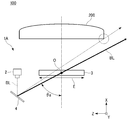
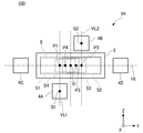
- FIG. 1 is a schematic view showing the configuration of a vehicle lamp 100 provided with a transmissive lighting device 1A.
- FIG. 2 is a schematic view showing the configuration of a vehicle lamp 100 provided with a reflective lighting device 1B.
- the XYZ Cartesian coordinate system is set, the X-axis direction is the front-rear direction of the lighting devices 1A and 1B (vehicle lighting equipment 100), and the Y-axis direction is the lighting devices 1A and 1B (vehicle lighting equipment 100).
- the left-right direction and the Z-axis direction of the above are shown as the up-down directions of the lighting devices 1A and 1B (vehicle lighting equipment 100), respectively.
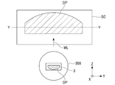
- the lighting device 1A of the present embodiment is a vehicle headlight that irradiates the illumination light W toward the front (+ X-axis direction) of the vehicle as the vehicle lighting tool 100 mounted on the vehicle.
- the present invention is applied to (headlamp).
- the illuminating device 1A includes a projection lens 200 that projects the illumination light WL toward the front of the vehicle, and is housed inside a lamp body (not shown) together with the projection lens 200. Consists of.
- the illumination device 1A is a transmission type wavelength conversion member 3A that emits a laser light source 2 that emits a laser beam BL that becomes excitation light and a fluorescent light YL that is excited by irradiation of the laser beam BL and has a wavelength conversion.
- a laser light scanning mechanism 4 that scans the laser light BL irradiated toward the wavelength conversion member 3A, and a reflector 5 that reflects the laser light BL scanned by the laser light scanning mechanism 4 toward the wavelength conversion member 3A. Is roughly equipped.
- the laser light source 2 is composed of a laser diode (LD) that emits, for example, a blue laser light (emission wavelength is about 450 nm) as the laser light BL.
- LD laser diode
- an LD that emits ultraviolet laser light may be used as the laser light BL.
- the wavelength conversion member 3A is composed of a plate-shaped phosphor plate containing yellow phosphor particles that are excited by irradiation with laser light BL and emit yellow light as fluorescent light YL.
- the wavelength conversion member 3A for example, a member containing phosphor particles made of a composite (sintered body) of YAG and alumina Al2O3 into which an activator such as cerium Ce has been introduced is used. ..
- the wavelength conversion member 3A may include a diffusing agent in order to control the light distribution characteristics of the illumination light WL emitted from the illumination device 1A.
- the laser light scanning mechanism 4 includes a MEMS mirror arranged in an optical path between the laser light source 2 and the wavelength conversion member 3A.
- the MEMS mirror is a movable mirror using MEMS technology, and controls the scanning direction and scanning speed of the laser beam BL scanned in the plane of the wavelength conversion member 3A.
- the reflector 5 is composed of a plane mirror arranged in an optical path between the wavelength conversion member 3A and the laser light scanning mechanism 4.
- the reflector 5 reflects the laser beam BL reflected by the MEMS mirror toward the back surface of the wavelength conversion member 3A.
- a part of the laser light (blue light) BL irradiated toward the back surface of the wavelength conversion member 3A is transmitted through the wavelength conversion member 3A while being diffused, and is irradiated by the laser light BL.
- fluorescent light (yellow light) YL is emitted
- the illumination light (white light) WL is emitted from the projection lens 200 in front by mixing these blue light and yellow light. It is possible to emit light toward.
- the lighting device 1B of the present embodiment illuminates, for example, toward the front of the vehicle (+ X-axis direction) as the vehicle lighting tool 100 mounted on the vehicle, similarly to the lighting device 1A.
- the present invention is applied to a vehicle headlamp that irradiates light W.
- the lighting device 1B constitutes the vehicle lighting tool 100 by being housed inside a lighting body (not shown) together with a projection lens 200 that projects the illumination light WL toward the front of the vehicle.
- the illumination device 1B includes a laser light source 2 that emits a laser beam BL that becomes excitation light, and a reflection type wavelength conversion member 3B that emits fluorescent light YL that is excited by irradiation of the laser beam BL and has a wavelength conversion.
- a laser light scanning mechanism 4 that scans the laser light BL irradiated toward the wavelength conversion member 3B, and a reflector 5 that reflects the laser light BL scanned by the laser light scanning mechanism 4 toward the wavelength conversion member 3B. Is roughly equipped.
- the lighting device 1B includes a reflection type wavelength conversion member 3B instead of the transmission type wavelength conversion member 3A, and the laser light source 2 and the laser light scanning mechanism 4 are arranged according to the arrangement of the wavelength conversion member 3B. It has basically the same configuration as the above-mentioned lighting device 1A except that the arrangement of the reflector 5 is changed.
- the wavelength conversion member 3B has a configuration in which the reflector 6 is arranged on the back surface side of the phosphor plate constituting the wavelength conversion member 3A.
- the reflector 6 reflects the laser light BL incident from the front side of the wavelength conversion member 3B and the fluorescent light YL excited in the wavelength conversion member 3B toward the front side of the wavelength conversion member 3B.
- the illumination device 1B of the present embodiment a part of the laser light (blue light) BL irradiated toward the front surface of the wavelength conversion member 3B is reflected by the wavelength conversion member 3B while being diffused, and the laser light BL is irradiated.
- the illumination light (white light) WL is projected forward by mixing the blue light and the yellow light while emitting the fluorescent light (yellow light) YL. It is possible to emit light toward the lens 200.
- the vehicle lighting equipment 100 of the present embodiment by providing the above-mentioned lighting devices 1A and 1B, as a passing beam (low beam), an illumination light WL that forms a low beam light distribution pattern including a cut-off line at the upper end, and traveling.
- the illumination light WL forming the high beam light distribution pattern above the low beam light distribution pattern can be projected toward the front of the vehicle by the projection lens 200.
- a light distribution variable headlamp that variably controls the light distribution pattern of the illumination light WL projected toward the front of the vehicle by scanning the laser light BL is used. It is also possible.
- an image for drawing is obtained by scanning the laser light BL separately from the illumination light WL projected toward the front of the vehicle. It is also possible to project the drawing light forming the light distribution pattern) toward the road surface by the projection lens 200.
- the incident angle of the laser light BL scanned by the laser light scanning mechanism 4 with respect to the wavelength conversion members 3A and 3B is the wavelength conversion members 3A and 3B.
- the laser beam BL is set at an angle that does not directly incident on the projection lens 200 when the lens is damaged, missing, or dropped off.
- the laser light scanned by the laser light scanning mechanism 4 is scanned even if the wavelength conversion members 3A and 3B are defective, damaged, or dropped. It is possible to prevent the BL from being directly emitted to the outside through the projection lens 200.
- the laser light source 2 and the laser scanning mechanism 4 have the upper side and the lower side of the light distribution pattern sandwiching the wavelength conversion member 3. It is located at a position corresponding to at least one of them, and is arranged so as to be offset from one side corresponding to the left side of the light distribution pattern and the other side corresponding to the right side of the light distribution pattern.
- the laser light source 2 and the laser scanning mechanism 4 of the illumination devices 1A and 1B of the present embodiment correspond to one side corresponding to the left side of the light distribution pattern and the other corresponding to the right side of the light distribution pattern with respect to the center of the wavelength conversion member. It is arranged on either side of the wavelength conversion member 3 so as to be offset from the center of the wavelength conversion member 3.
- the center P of the scanning range S of the laser light BL passes through the center Q of the laser light scanning mechanism 4. It is located at the intersection of the vertical line VL corresponding to the vertical direction and the horizontal line HL corresponding to the horizontal direction of the light distribution pattern passing through the center O of the laser beam irradiation region E.
- the laser light source 2, the laser light scanning mechanism 4, and the reflector 5 are arranged in accordance with the arrangement of the transmission type wavelength conversion member 3A and the reflection type wavelength conversion member 3B described above. It has basically the same configuration except that it has been changed.
- the transmission type wavelength conversion member 3A and the reflection type wavelength conversion member 3B are collectively treated as the "wavelength conversion member 3", and the transmission type illumination device 1A is referred to in FIGS. 3 and 4.
- the explanation will be given by way of exemplifying the present invention, the present invention can be similarly applied to the reflective lighting device 1B.
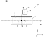
- FIG. 3 is a front view of the lighting device 1A showing the positional relationship between the center O of the laser light irradiation region E and the center P of the scanning range S of the laser light BL.
- FIG. 4 is a top view of the lighting device 1A showing the positional relationship between the center O of the laser light irradiation region E and the center P of the scanning range S of the laser light BL.
- the wavelength conversion member 3 has a rectangular shape in a plan view (X-axis direction view) corresponding to a light distribution pattern corresponding to the scanning range S of the laser light BL.
- the longitudinal direction of the laser irradiation region E corresponds to the left-right direction (Y-axis direction) of the light distribution pattern
- the lateral direction of the laser irradiation region E corresponds to the vertical direction (Z-axis direction) of the light distribution pattern. ..
- the laser light irradiation region E has a so-called horizontally long shape in which the width corresponding to the left-right direction of the light distribution pattern is longer than the height corresponding to the vertical direction of the light distribution pattern when the wavelength conversion member 3 is viewed in a plan view.
- the light distribution pattern when the illumination light WL emitted toward the front of the vehicle lighting tool 100 is projected onto the virtual vertical screen facing the vehicle lighting tool 100 is also horizontally long.
- the laser scanning mechanism 4 is arranged and controlled so that the scanning range S of the laser beam L with respect to the laser scanning region E of the wavelength conversion member 3 is also horizontally long.
- the laser scanning mechanism 4 is located on the upper side or the lower side (in the present embodiment) of the light distribution pattern sandwiching the horizontally long wavelength conversion member 3 in the lateral direction. It is in the position corresponding to the upper side).
- the incident angle of the laser light BL incident on the center O of the laser light irradiation region E is defined as ⁇ a.
- FIG. 5 shows a case where the laser scanning mechanism 4 is located at a position corresponding to the left side or the right side (left side in the present embodiment) which is the longitudinal direction of the light distribution pattern sandwiching the wavelength conversion member 3.
- the incident angle of the laser light BL incident on the center O of the laser light irradiation region E is set to ⁇ b.
- the MEMS mirror of the laser scanning mechanism 4 is operated at the same deflection angle. Assuming, the incident angle ⁇ a shown in FIG. 4 can be made smaller than the incident angle ⁇ b shown in FIG.
- the laser scanning mechanism 4 when the above-mentioned laser scanning mechanism 4 is located at a position corresponding to the upper side or the lower side of the light distribution pattern sandwiching the wavelength conversion member 3 in the lateral direction, the laser light BL irradiated to the wavelength conversion member 3 It is possible to reduce the spot size. This makes it possible to increase the resolution of the light distribution pattern formed by the ADB described above.
- the upper laser light scanning mechanism 4 corresponds to one side corresponding to the left side in the longitudinal direction of the light distribution pattern and the other corresponding to the right side in the longitudinal direction of the light distribution pattern.
- ⁇ c be the angle of incidence with respect to the normal line (X-axis) of 3, and let be the incident vector Vc of the laser beam BL above it.
- FIG. 7 shows a case where the laser light scanning mechanism 4 is located on the upper center side of the wavelength conversion member 3.
- the incident angle of the upper laser light BL incident on the right end of the laser light irradiation region E with respect to the normal line (X axis) of the wavelength conversion member 3 is ⁇ d, and the incident vector of the upper laser light BL. Let it be Vd.
- the MEMS mirror of the laser scanning mechanism 4 is operated at the same deflection angle. Assuming that, the incident angle ⁇ c shown in FIG. 6 can be made smaller than the incident angle ⁇ d shown in FIG. 7.
- the speed at which the MEMS mirror is reciprocally swung is determined in the laser light irradiation region.
- the maximum is near the center of E, and the minimum is near the left and right ends of the laser beam irradiation region E.
- the luminous intensity distribution in the plane of the laser light irradiation region E becomes relatively high in the vicinity of the left and right ends of the laser light irradiation region E where the speed becomes low.
- a correction mirror can be used as a means for optically correcting this luminous intensity distribution.
- the correction mirror can flatten the luminous intensity distribution by optically stretching the vicinity of the left and right ends of the laser beam irradiation region E where the brightness becomes high.
- the spot size becomes large near both the left and right ends of the laser beam irradiation region E.
- the wider the scanning range S of the laser light BL the more correction is required near the left and right ends of the laser light irradiation area E, and the larger the spot size becomes.
- the upper laser scanning mechanism 4 shifts the center P of the scanning range S of the upper laser light BL described above to the right with respect to the center O of the laser light irradiation region E, thereby shifting the laser light irradiation region E.
- the incident angle ⁇ c near the left and right ends of the light intensity distribution in the plane can be reduced.
- the scanning range S of the upper laser light BL can be reduced, and the spot size becomes large near the left and right ends of the laser light irradiation area E. It is possible to prevent it from growing. This makes it possible to increase the resolution of the light distribution pattern formed by the ADB described above.
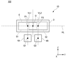
- FIG. 8 is a schematic view showing the configuration of the vehicle lamp 100 provided with the lighting device 1C.
- FIG. 9 shows the positional relationship between the center O of the laser light irradiation region E of the lighting device 1C, the center P1 of the scanning range S1 of the laser light BL1 on the lower left side, and the center P2 of the scanning range S2 of the laser light BL2 on the upper right side. It is a front view which shows.
- the same parts as those of the lighting devices 1A and 1B will be omitted and the same reference numerals will be given in the drawings.
- the transmission type wavelength conversion member 3A and the reflection type wavelength conversion member 3B shall be collectively treated as the "wavelength conversion member 3", and the transmission type illumination device 1C is illustrated in FIGS. Although the description will be given, the present invention can be similarly applied to a reflective lighting device.
- the vehicle lighting equipment 100 provided with the lighting device 1C of the present embodiment is located at a position corresponding to the lower side of the light distribution pattern sandwiching the wavelength conversion member 3 in the lateral direction.
- the laser light source 3A and the laser scanning mechanism 4A on the lower left side which are arranged so as to be shifted to the left side (one side) which is the longitudinal direction of the light distribution pattern, and the light distribution pattern sandwiching the wavelength conversion member 3 in the lateral direction. It has a laser light source 3B and a laser scanning mechanism 4B on the upper right side, which are located at positions corresponding to the upper side and are arranged so as to be shifted to the right side (the other side) which is the longitudinal direction of the light distribution pattern.
- the laser light source 3A and the laser scanning mechanism 4A of the vehicle lamp 100 provided with the lighting device 1C of the present embodiment are shifted to the left side (one side) in the longitudinal direction of the light distribution pattern with respect to the center of the wavelength conversion member 3. Is arranged.
- the laser light source 3B and the laser scanning mechanism 4B of the vehicle lamp 100 provided with the lighting device 1C of the present embodiment are shifted to the right side (the other side) in the longitudinal direction of the light distribution pattern with respect to the center of the wavelength conversion member 3. Is arranged.
- the laser light scanning mechanism 4A on the lower left side scans the laser light BL1 on the lower left side (one side) emitted from the laser light source 2A on the lower left side toward the laser light irradiation region E, thereby causing the laser light BL1 on the lower left side.
- a light distribution pattern corresponding to the scanning range S1 is formed.
- the laser light scanning mechanism 4B on the upper right side scans the laser light BL2 on the upper right side (the other side) emitted from the laser light source 2B on the upper right side toward the laser light irradiation region E, thereby causing the laser light BL2 on the upper right side.
- a light distribution pattern corresponding to the scanning range S2 is formed.
- the light distribution pattern corresponding to the scanning range S1 of the laser light BL1 on the lower left side and the light distribution pattern corresponding to the scanning range S2 of the laser light BL2 on the upper right side are superimposed. It forms one synthetic light distribution pattern.
- the center P1 of the scanning range S1 of the laser light BL1 on the lower left side passes through the center Q1 of the laser light scanning mechanism 4A on the lower left side. It is located at the intersection of the vertical line VL1 corresponding to the vertical direction of the light distribution pattern and the horizontal line HL corresponding to the horizontal direction of the light distribution pattern passing through the center O of the laser light irradiation region E.
- the center P2 of the scanning range S2 of the laser beam BL2 on the upper right side is the vertical line VL2 corresponding to the vertical direction of the light distribution pattern passing through the center Q2 of the laser light scanning mechanism 4B on the upper right side, and the laser beam irradiation. It is located at the intersection with the horizontal line HL corresponding to the left-right direction of the light distribution pattern passing through the center O of the region E.
- P2 is located on the left side and the right side of the center O of the laser beam irradiation region E.
- the angle of incidence with respect to 3 is set to an angle at which the laser beams BL1 and BL2 do not directly incident on the projection lens 200 when the wavelength conversion member 3 is damaged, missing, or dropped off.
- the laser light scanning mechanisms 4A and 4B on the lower left side and the upper right side scan. It is possible to prevent the laser beams BL1 and BL2 on the lower left side and the upper right side from being directly emitted to the outside through the projection lens 200.
- the laser light scanning mechanisms 4A and 4B on the lower left side and the upper right side described above correspond to the lower side and the upper side in the lateral direction of the light distribution pattern sandwiching the wavelength conversion member 3.
- the light distribution pattern is arranged so as to be offset from one side corresponding to the left side in the longitudinal direction of the light distribution pattern and the other side corresponding to the right side in the longitudinal direction of the light distribution pattern.
- the laser light scanning mechanisms 4A and 4B of the illumination device 1C of the present embodiment have one side corresponding to the left side in the longitudinal direction of the light distribution pattern and the other side corresponding to the right side in the longitudinal direction of the light distribution pattern. They are arranged so as to be offset from the center of the wavelength conversion member 3.
- the center P2 is located on the left side and the right side of the center O of the laser beam irradiation region E.
- the vehicle lamp 100 provided with the lighting device 1C of the present embodiment it is possible to reduce the spot size of the laser beams BL1 and BL2 on the lower left side and the upper right side irradiated on the wavelength conversion member 3. As a result, it is possible to increase the resolution of the light distribution pattern formed by the above-mentioned ADB.
- FIG. 10 is a schematic view showing the configuration of the vehicle lamp 100 provided with the lighting device 1D.
- FIG. 11 shows the positional relationship between the center O of the laser light irradiation region E of the lighting device 1D, the center P1 of the scanning range S1 of the laser light BL1 on the lower left side, and the center P2 of the scanning range S2 of the laser light BL2 on the lower right side. It is a front view which shows.
- the same parts as those of the lighting devices 1A and 1B will be omitted and the same reference numerals will be given in the drawings.
- the transmission type wavelength conversion member 3A and the reflection type wavelength conversion member 3B are collectively treated as the "wavelength conversion member 3", and while exemplifying the transmission type illumination device 1D in FIGS. 10 and 11, the transmission type illumination device 1D is illustrated.
- the present invention can be similarly applied to a reflective lighting device.
- the vehicle lighting equipment 100 provided with the lighting device 1D of the present embodiment is located at a position corresponding to the lower side of the light distribution pattern sandwiching the wavelength conversion member 3 in the lateral direction.
- the laser light source 3A and the laser scanning mechanism 4A on the lower left side which are arranged so as to be shifted to the left side (one side) which is the longitudinal direction of the light distribution pattern, and the right side (the other side) which is the longitudinal direction of the light distribution pattern. It has a laser light source 3B on the lower right side and a laser scanning mechanism 4B arranged in a staggered manner. Other than that, it has basically the same configuration as the vehicle lamp 100 provided with the lighting device 1C.
- the laser light source 3A and the laser scanning mechanism 4A of the vehicle lamp 100 provided with the lighting device 1D of the present embodiment are shifted to the left side (one side) in the longitudinal direction of the light distribution pattern with respect to the center of the wavelength conversion member 3. Is arranged.
- the laser light source 3B and the laser scanning mechanism 4B of the vehicle lamp 100 provided with the lighting device 1D of the present embodiment are shifted to the right side (the other side) in the longitudinal direction of the light distribution pattern with respect to the center of the wavelength conversion member 3. Is arranged.
- the laser light scanning mechanism 4A on the lower left side scans the laser light BL1 on the lower left side (one side) emitted from the laser light source 2A on the lower left side toward the laser light irradiation region E, thereby causing the laser light BL1 on the lower left side.
- a light distribution pattern corresponding to the scanning range S1 is formed.
- the laser light scanning mechanism 4B on the lower right side scans the laser light BL2 on the lower right side (the other side) emitted from the laser light source 2A on the lower right side toward the laser light irradiation region E, thereby causing the laser light BL2 on the lower right side.
- a light distribution pattern corresponding to the scanning range S2 is formed.
- the light distribution pattern corresponding to the scanning range S1 of the laser beam BL1 on the lower left side and the light distribution pattern corresponding to the scanning range S2 of the laser beam BL2 on the lower right side are superimposed. It forms one synthetic light distribution pattern.
- the center P1 of the scanning range S1 of the laser light BL1 on the lower left side passes through the center Q1 of the laser light scanning mechanism 4A on the lower left side. It is located at the intersection of the vertical line VL1 corresponding to the vertical direction of the light distribution pattern and the horizontal line HL corresponding to the horizontal direction of the light distribution pattern passing through the center O of the laser light irradiation region E.
- the center P2 of the scanning range S2 of the laser beam BL2 on the lower right side is the vertical line VL2 corresponding to the vertical direction of the light distribution pattern passing through the center Q2 of the laser light scanning mechanism 4B on the lower right side, and the laser beam irradiation. It is located at the intersection with the horizontal line HL corresponding to the left-right direction of the light distribution pattern passing through the center O of the region E.
- P2 is located on the left side and the right side of the center O of the laser beam irradiation region E.
- the wavelength conversion member of the laser light BL1 and BL2 on the lower left side and the lower right side scanned by the laser light scanning mechanisms 4A and 4B on the lower left side and the lower right side described above.
- the angle of incidence with respect to 3 is set to an angle at which the laser beams BL1 and BL2 do not directly incident on the projection lens 200 when the wavelength conversion member 3 is damaged, missing, or dropped off.
- the laser light scanning mechanisms 4A and 4B on the lower left side and the lower right side scan. It is possible to prevent the laser beams BL1 and BL2 on the lower left side and the lower right side from being directly emitted to the outside through the projection lens 200.
- the positions of the laser light scanning mechanisms 4A and 4B on the lower left side and the lower right side described above correspond to the lower side of the light distribution pattern sandwiching the wavelength conversion member 3 in the lateral direction. And, they are arranged so as to be offset from one side corresponding to the left side in the longitudinal direction of the light distribution pattern and the other side corresponding to the right side in the longitudinal direction of the light distribution pattern.
- the laser light scanning mechanisms 4A and 4B of the illumination device 1D of the present embodiment have one side corresponding to the left side in the longitudinal direction of the light distribution pattern and the other side corresponding to the right side in the longitudinal direction of the light distribution pattern. They are arranged so as to be offset from the center of the wavelength conversion member 3.
- the center P2 is located on the left side and the right side of the center O of the laser beam irradiation region E.
- the vehicle lamp 100 provided with the lighting device 1D of the present embodiment it is possible to reduce the spot size of the laser beams BL1 and BL2 on the lower left side and the lower right side irradiated on the wavelength conversion member 3. As a result, it is possible to increase the resolution of the light distribution pattern formed by the above-mentioned ADB.
- FIG. 12 is a schematic view showing the configuration of the vehicle lamp 100 provided with the lighting device 1E.
- FIG. 11 shows the center O of the laser light irradiation region E of the lighting device 1E, the center P1 of the scanning range S1 of the laser light BL1 on the lower left side, the center P2 of the scanning range S2 of the laser light BL2 on the lower right side, and the upper center side.
- It is a front view which shows the positional relationship with the center P3 of the scanning range S3 of a laser beam BL3.
- the same parts as those of the lighting device 1D will be omitted and the same reference numerals will be given in the drawings.
- the transmission type wavelength conversion member 3A and the reflection type wavelength conversion member 3B are collectively treated as the "wavelength conversion member 3", and while exemplifying the transmission type lighting device 1E in FIGS. 12 and 13, the transmission type lighting device 1E is illustrated.
- the present invention can be similarly applied to a reflective lighting device.
- the vehicle lamp 100 provided with the lighting device 1E of the present embodiment has a short light distribution pattern sandwiching the wavelength conversion member 3 in addition to the configuration of the lighting device 1D. It has a laser light source 2C and a laser scanning mechanism 4C on the upper center side additionally arranged on either the upper side (one side) or the lower side (the other side) (upper side in this embodiment) in the direction. ..
- the laser light scanning mechanism 4C on the upper center side scans the laser light BL3 on the upper center side (additional) emitted from the laser light source 2C on the upper center side toward the laser light irradiation region E, thereby scanning the laser light BL3 on the upper center side.
- a light distribution pattern corresponding to the scanning range S3 of the laser light BL3 is formed.
- the light distribution pattern corresponding to the scanning range S1 of the laser beam BL1 on the lower left side the light distribution pattern corresponding to the scanning range S2 of the laser light BL2 on the lower right side, and the light distribution pattern on the upper center side.
- One synthetic light distribution pattern is formed by superimposing the laser light BL3 with the light distribution pattern according to the scanning range S3.
- the center P3 of the scanning range S3 of the laser light BL3 on the upper center side is the center Q3 of the laser light scanning mechanism 4C on the upper center side. It is located at the intersection of the vertical line VL3 corresponding to the vertical direction of the light distribution pattern passing through the laser beam and the horizontal line HL corresponding to the horizontal direction of the light distribution pattern passing through the center O of the laser beam irradiation region E.
- the center P3 of the scanning range S3 of the laser beam BL3 on the upper center side coincides with the center O of the laser beam irradiation region E.
- the lower left side, the lower right side, and the upper center side scanned by the laser light scanning mechanisms 4A, 4B, and 4C on the lower left side, the lower right side, and the upper center side described above.
- the angle of incidence of the laser beams BL1, BL2, and BL3 on the wavelength conversion member 3 is the angle at which the laser beams BL1, BL2, and BL3 do not directly incident on the projection lens 200 when the wavelength conversion member 3 is damaged, missing, or dropped. Is set to.
- the laser light scanning mechanism 4A on the lower left side, the lower right side, and the upper center side. , 4B, 4C can prevent the laser beams BL1, BL2, and BL3 on the lower left side, the lower right side, and the upper center side from being directly emitted to the outside through the projection lens 200.
- the positions of the laser light scanning mechanisms 4A and 4B on the lower left side and the lower right side described above correspond to the lower side of the light distribution pattern sandwiching the wavelength conversion member 3 in the lateral direction.
- the laser light scanning mechanism 4C on the central side of the lower upper portion is located at a position corresponding to the upper side of the light distribution pattern sandwiching the wavelength conversion member 3 in the lateral direction.
- the laser light scanning mechanisms 4A and 4B on the lower left side and the lower right side are on one side corresponding to the left side in the longitudinal direction of the light distribution pattern and the other side corresponding to the right side in the longitudinal direction of the light distribution pattern. Each is staggered.
- the laser light scanning mechanisms 4A and 4B of the illumination device 1E of the present embodiment have one side corresponding to the left side in the longitudinal direction of the light distribution pattern and the other side corresponding to the right side in the longitudinal direction of the light distribution pattern. They are arranged so as to be offset from the center of the wavelength conversion member 3.
- the center P2 is located on the left side and the right side of the center O of the laser beam irradiation region E.
- the spot sizes of the laser beams BL1, BL2, and BL3 on the lower left side, the lower right side, and the upper center side irradiated to the wavelength conversion member 3 are reduced. Is possible. As a result, it is possible to increase the resolution of the light distribution pattern formed by the above-mentioned ADB.
- FIG. 14 is a schematic view showing the configuration of the vehicle lamp 100 provided with the lighting device 1F.
- FIG. 15 shows the center O of the laser light irradiation region E of the lighting device 1F, the center P1 of the scanning range S1 of the laser light BL1 on the lower left side, the center P2 of the scanning range S2 of the laser light BL2 on the upper right side, and the laser light on the right side.
- It is a front view which shows the positional relationship with the center P3 of the scanning range S3 of BL3.
- the same parts as those of the lighting device 1C will be omitted and the same reference numerals will be given in the drawings.
- the transmission type wavelength conversion member 3A and the reflection type wavelength conversion member 3B are collectively treated as the "wavelength conversion member 3", and while exemplifying the transmission type lighting device 1F in FIGS. 14 and 15, the transmission type lighting device 1F is illustrated.
- the present invention can be similarly applied to a reflective lighting device.
- the vehicle lamp 100 provided with the lighting device 1F of the present embodiment is added to the configuration of the lighting device 1C in the longitudinal direction of the light distribution pattern sandwiching the wavelength conversion member 3. It has a laser light source 2C and a laser scanning mechanism 4C on the right side additionally arranged on either the left side (one side) or the right side (the other side) (the right side in this embodiment).
- the laser light scanning mechanism 4C on the right side scans the laser light BL3 on the right side (additional) radiated from the laser light source 2C on the right side toward the laser light irradiation region E, so that the scanning range S3 of the laser light BL3 on the right side is reached. Form the corresponding light distribution pattern.
- the light distribution pattern corresponding to the scanning range S1 of the laser light BL1 on the lower left side the light distribution pattern corresponding to the scanning range S2 of the laser light BL2 on the upper right side, and the laser light on the right side.
- One synthetic light distribution pattern is formed by superimposing the light distribution pattern according to the scanning range S3 of BL3.
- the center P3 of the scanning range S3 of the laser light BL3 on the right side is at a position coincided with the center O of the laser light irradiation region E. ..
- the angle of incidence of BL2 and BL3 on the wavelength conversion member 3 is set to an angle at which the laser beams BL1, BL2 and BL3 do not directly incident on the projection lens 200 when the wavelength conversion member 3 is damaged, missing or dropped. There is.
- the laser light scanning mechanisms 4A, 4B on the lower left side, the upper right side, and the right side It is possible to prevent the lower left side, upper right side and right side laser beams BL1, BL2 and BL3 scanned by 4C from being directly emitted to the outside through the projection lens 200.
- the laser light scanning mechanisms 4A and 4B on the lower left side and the upper right side described above correspond to the lower side and the upper side in the lateral direction of the light distribution pattern sandwiching the wavelength conversion member 3.
- the light distribution pattern is arranged so as to be offset from one side corresponding to the left side in the longitudinal direction of the light distribution pattern and the other side corresponding to the right side in the longitudinal direction of the light distribution pattern.
- the laser light scanning mechanisms 4A and 4B of the illumination device 1F of the present embodiment have one side corresponding to the left side in the longitudinal direction of the light distribution pattern and the other side corresponding to the right side in the longitudinal direction of the light distribution pattern. They are arranged so as to be offset from the center of the wavelength conversion member 3.
- the center P1 of the scanning range S1 of the laser light BL1 on the lower left side and the scanning range S2 of the laser light BL2 on the upper right side The center P2 is located on the left side and the right side of the center O of the laser beam irradiation region E.
- the vehicle lamp 100 provided with the lighting device 1F of the present embodiment it is possible to reduce the spot size of the laser beams BL1 and BL2 on the lower left side and the upper right side irradiated on the wavelength conversion member 3. As a result, it is possible to increase the resolution of the light distribution pattern formed by the above-mentioned ADB.
- the wavelength conversion member 3 is irradiated rather than the scanning ranges S1 and S2 in the left-right direction of the laser beams BL1 and BL2 on the lower left side and the upper right side to be irradiated to the wavelength conversion member 3 described above.
- the scanning range S3 in the left-right direction of the laser beam BL3 on the right side the spot size of the laser beam BL3 on the right side can be reduced.
- the lighting device 1F of the present embodiment it is easier to spatially arrange the laser light source 2C and the laser scanning mechanism 4C to be additionally arranged than the lighting device 1E.
- FIG. 16 is a schematic view showing the configuration of the vehicle lamp 100 provided with the lighting device 1G.
- FIG. 17 shows the center O of the laser light irradiation region E of the lighting device 1C, the center P1 of the scanning range S1 of the laser light BL1 on the lower left side, the center P2 of the scanning range S2 of the laser light BL2 on the lower right side, and the laser on the upper left side.
- It is a front view which shows the positional relationship with the center P3 of the scanning range S3 of the light BL3, and the center P4 of the scanning range S4 of the laser light BL4 on the upper right side.
- the same parts as those of the lighting device 1D will be omitted and the same reference numerals will be given in the drawings.
- the transmission type wavelength conversion member 3A and the reflection type wavelength conversion member 3B shall be collectively treated as the "wavelength conversion member 3", and the transmission type illumination device 1G is illustrated in FIGS. 16 and 17 and the same.
- the present invention can be similarly applied to a reflective lighting device.
- the vehicle lighting tool 100 provided with the lighting device 1G of the present embodiment has a short light distribution pattern sandwiching the wavelength conversion member 3 in addition to the configuration of the lighting device 1D.
- the laser light source 3C and the laser scanning mechanism 4C on the upper left side which are located at positions corresponding to the upper side of the light distribution pattern and are shifted to the left side (one side) which is the longitudinal direction of the light distribution pattern, and the light distribution pattern. It has a laser light source 3D on the upper right side and a laser scanning mechanism 4D arranged so as to be offset to the right side (the other side) in the longitudinal direction.
- it has basically the same configuration as the lighting device 100 for a vehicle equipped with the lighting device 1D.
- the laser light source 3C and the laser scanning mechanism 4C of the vehicle lamp 100 provided with the lighting device 1G of the present embodiment are shifted to the left side (one side) in the longitudinal direction of the light distribution pattern with respect to the center of the wavelength conversion member 3. Is arranged.
- the laser light source 3D and the laser scanning mechanism 4D of the vehicle lamp 100 provided with the lighting device 1G of the present embodiment are shifted to the right side (the other side) in the longitudinal direction of the light distribution pattern with respect to the center of the wavelength conversion member 3. Is arranged.
- the laser light scanning mechanism 4C on the upper left side scans the laser light BL3 on the upper left side (one side) emitted from the laser light source 2C on the upper left side toward the laser light irradiation region E, thereby causing the laser light BL3 on the upper left side.
- a light distribution pattern corresponding to the scanning range S3 is formed.
- the laser light scanning mechanism 4D on the upper right side scans the laser light BL2 on the upper right side (the other side) emitted from the laser light source 2D on the upper right side toward the laser light irradiation region E, thereby causing the laser light BL2 on the upper right side.
- a light distribution pattern corresponding to the scanning range S2 is formed.
- the light distribution pattern corresponding to the scanning range S1 of the laser beam BL1 on the lower left side the light distribution pattern corresponding to the scanning range S2 of the laser light BL2 on the lower right side, and the laser on the upper left side.
- One synthetic light distribution pattern is formed by superimposing the light distribution pattern corresponding to the scanning range S3 of the light BL3 and the light distribution pattern corresponding to the scanning range S4 of the laser light BL4 on the upper right side.
- the center P3 of the scanning range S3 of the laser light BL3 on the upper left side passes through the center Q3 of the laser light scanning mechanism 4C on the upper left side. It is located at the intersection of the vertical line VL3 corresponding to the vertical direction of the light distribution pattern and the horizontal line HL corresponding to the horizontal direction of the light distribution pattern passing through the center O of the laser light irradiation region E.
- the center P4 of the scanning range S4 of the laser beam BL4 on the upper right side is the vertical line VL4 corresponding to the vertical direction of the light distribution pattern passing through the center Q4 of the laser light scanning mechanism 4D on the upper right side, and the laser beam irradiation. It is located at the intersection with the horizontal line HL corresponding to the left-right direction of the light distribution pattern passing through the center O of the region E.
- P4 is located on the left side and the right side of the center O of the laser beam irradiation region E.
- the wavelength conversion members of the upper left and upper right laser beams BL3 and BL4 scanned by the above-mentioned upper left and upper right laser light scanning mechanisms 4C and 4D.
- the angle of incidence with respect to 3 is set to an angle at which the laser beams BL3 and BL4 do not directly incident on the projection lens 200 when the wavelength conversion member 3 is damaged, missing, or dropped off.
- the laser light scanning mechanisms 4C and 4D on the upper left side and the upper right side scan. It is possible to prevent the laser beams BL3 and BL4 on the upper left side and the upper right side from being directly emitted to the outside through the projection lens 200.
- the above-mentioned upper left side and upper right side laser light scanning mechanisms 4C and 4D are positioned at positions corresponding to the upper side of the light distribution pattern sandwiching the wavelength conversion member 3 in the lateral direction. Moreover, they are arranged so as to be offset from one side corresponding to the left side in the longitudinal direction of the light distribution pattern and the other side corresponding to the right side in the longitudinal direction of the light distribution pattern.
- the laser light scanning mechanisms 4C and 4D of the illumination device 1G of the present embodiment have one side corresponding to the left side in the longitudinal direction of the light distribution pattern and the other side corresponding to the right side in the longitudinal direction of the light distribution pattern. They are arranged so as to be offset from the center of the wavelength conversion member 3.
- the center P4 is located on the left side and the right side of the center O of the laser beam irradiation region E.
- the vehicle lamp 100 provided with the lighting device 1G of the present embodiment it is possible to reduce the spot size of the laser beams BL3 and BL4 on the upper left side and the upper right side irradiated on the wavelength conversion member 3. As a result, it is possible to increase the resolution of the light distribution pattern formed by the above-mentioned ADB.
- FIG. 18 is a schematic view showing the configuration of the vehicle lamp 100 provided with the lighting device 1H.
- FIG. 19 shows the center O of the laser light irradiation region E of the illuminating device 1H, the center P1 of the scanning range S1 of the laser light BL1 on the lower left side, the center P2 of the scanning range S2 of the laser light BL2 on the upper right side, and the laser light on the left side.
- It is a front view which shows the positional relationship with the center P3 of the scanning range S3 of BL3, and the center P4 of the scanning range S4 of the laser light BL4 on the right side.
- the same parts as those of the lighting device 1C will be omitted and the same reference numerals will be given in the drawings.
- the transmission type wavelength conversion member 3A and the reflection type wavelength conversion member 3B are collectively treated as the "wavelength conversion member 3", and while exemplifying the transmission type lighting device 1F in FIGS. 18 and 19, the transmission type lighting device 1F is illustrated.
- the present invention can be similarly applied to a reflective lighting device.
- the vehicle lighting tool 100 provided with the lighting device 1H of the present embodiment is added to the configuration of the lighting device 1C in the longitudinal direction of the light distribution pattern sandwiching the wavelength conversion member 3.
- the laser light scanning mechanism 4C on the left side scans the laser light BL3 on the left side (additional) radiated from the laser light source 2C on the left side toward the laser light irradiation region E, so that the scanning range S3 of the laser light BL3 on the left side is reached. Form the corresponding light distribution pattern.
- the laser light scanning mechanism 4D on the right side scans the laser light BL4 on the right side (additional) emitted from the laser light source 2D on the right side toward the laser light irradiation area E, thereby increasing the scanning range S4 of the laser light BL4 on the right side. Form the corresponding light distribution pattern.
- the light distribution pattern corresponding to the scanning range S1 of the laser light BL1 on the lower left side the light distribution pattern corresponding to the scanning range S2 of the laser light BL2 on the upper right side, and the laser light on the left side.
- One synthetic light distribution pattern is formed by superimposing the light distribution pattern corresponding to the scanning range S3 of BL3 and the light distribution pattern corresponding to the scanning range S4 of the laser light BL4 on the right side.
- the center P3 of the scanning range S3 of the laser light BL3 on the left side is on the left side with respect to the center O of the laser light irradiation region E.
- the laser light scanning mechanism 4C is located on the opposite side (right side) to the side where the laser light scanning mechanism 4C is arranged.
- the center P4 of the scanning range S4 of the laser light BL4 on the right side is on the side (left side) opposite to the side where the laser light scanning mechanism 4D on the right side is arranged with respect to the center O of the laser light irradiation region E. positioned.
- the incident angles of the left and right laser beams BL3 and BL4 scanned by the left and right laser light scanning mechanisms 4C and 4D described above with respect to the wavelength conversion member 3 are
- the angle is set so that the laser beams BL3 and BL4 do not directly incident on the projection lens 200.
- the left and right laser light scanning mechanisms 4C and 4D scan the wavelength conversion member 3. It is possible to prevent the left and right laser beams BL3 and BL4 from being directly emitted to the outside through the projection lens 200.
- the centers P3 and P4 of the scanning ranges S3 and S4 of the left and right laser beams BL3 and BL4 described above are the lasers on the left and right sides with respect to the center O of the laser light irradiation region E.
- the optical scanning mechanisms 4C and 4D By locating the optical scanning mechanisms 4C and 4D on the side opposite to the side on which the optical scanning mechanisms 4C and 4D are arranged, it is possible to reduce the spot size of the laser beams BL3 and BL4 irradiated to the wavelength conversion member 3. This makes it possible to increase the resolution of the light distribution pattern formed by the ADB described above.
- the wavelength conversion member 3 is irradiated rather than the scanning ranges S1 and S2 in the left-right direction of the laser beams BL1 and BL2 on the lower left side and the upper right side to be irradiated to the wavelength conversion member 3 described above.
- the scanning ranges S3 and S4 of the left and right laser beams BL3 and BL4 in the left-right direction it is possible to reduce the spot size of the left and right laser beams BL3 and BL4.
- the lighting device 1H of the present embodiment it is easier to spatially arrange the laser light sources 2C and 2D and the laser scanning mechanisms 4C and 4D to be additionally arranged than the above-mentioned lighting device 1G.
- Examples 1-1, 1-2 and Comparative Example 1 Examples 2-1, 2-2 and Comparative Example 2, Examples 3-1, 3-2 and Comparative Example 3, Example 4
- the illuminating devices of -1, 4-2 and Comparative Example 4 are used to irradiate the illuminating light WL toward the front of the illuminating device with the projection lens 200, and the virtual device faces the illuminating device.
- a simulation was performed in which a light source image of a light distribution pattern DP formed in the plane of the wavelength conversion member 3 was projected onto the vertical screen SC.
- the illumination light WL emitted from each illumination device was adjusted.
- Example 1-1 a transmissive lighting device corresponding to the lighting device 1E was used.
- the lower left side is referred to as "MEMS1”
- the lower right side is referred to as "MEMS2”
- the upper center side is referred to as "MEMS3”.
- the scanning ranges S1 to S3 of the laser beams BL1 to BL3 by MEMS1 to MEMS3 and their centers P1 to P3 are adjusted as shown in Table 1 below, and the light distribution pattern corresponding to the scanning ranges S1 to S3 of the laser beams BL1 to BL3.
- a light distribution pattern DP satisfying the light intensity distribution of the high beam light distribution pattern as shown in FIG. 21 was formed.
- Table 1 for the centers P1 to P3 of each scanning range S1 to S3, the center O of the laser light irradiation region E on the horizontal line HL is set to 0 [mm] with respect to the center O of the laser light irradiation region E.
- the left side is represented as the minus (-) side, and the right side is represented as the plus (+) side.
- the scanning ranges S1 to S3 are scanning widths on the horizontal line HL.
- Tables 2 to 12 shown below are also represented in the same manner.
- Example 1-2 a transmissive lighting device corresponding to the above lighting device 1F was used.
- the lower left side is referred to as "MEMS1”
- the upper right side is referred to as "MEMS2”
- the right side is referred to as "MEMS3”.
- the scanning ranges S1 to S3 of the laser beams BL1 to BL3 and their centers P1 to P3 are adjusted as shown in Table 2 below, and the light distribution patterns corresponding to the scanning ranges S1 to S3 of the laser beams BL1 to BL3 are superposed.
- a light distribution pattern DP that satisfies the light intensity distribution of the high beam light distribution pattern as shown in FIG. 21 was formed.
- Comparative Example 1 of the three MEMS1 to MEMS3 constituting the transmissive lighting device, "MEMS1” is arranged on the left side, “MEMS2" on the right side, and “MEMS3” on the upper side with the wavelength conversion member 3 sandwiched between them.
- the scanning ranges S1 to S3 of the laser beams BL1 to BL3 and their centers P1 to P3 by these three MEMS1 to MEMS3 are adjusted as shown in Table 3 below, and the scanning ranges S1 to S3 of the laser beams BL1 to BL3 are adjusted.
- a light distribution pattern DP satisfying the luminous intensity distribution of the high beam light distribution pattern as shown in FIG. 21 was formed.
- Example 2-1 a reflective lighting device corresponding to the lighting device 1E was used.
- the lower left side is referred to as "MEMS1”
- the lower right side is referred to as "MEMS2”
- the upper center side is referred to as "MEMS3”.
- the scanning ranges S1 to S3 of the laser beams BL1 to BL3 by MEMS1 to MEMS3 and their centers P1 to P3 are adjusted as shown in Table 4 below, and the light distribution pattern corresponding to the scanning ranges S1 to S3 of the laser beams BL1 to BL3.
- a light distribution pattern DP satisfying the light intensity distribution of the high beam light distribution pattern as shown in FIG. 21 was formed.
- Example 2-2 a reflection type lighting device corresponding to the above lighting device 1F was used.
- the lower left side is referred to as "MEMS1”
- the upper right side is referred to as "MEMS2”
- the right side is referred to as "MEMS3”.
- the scanning ranges S1 to S3 of the laser beams BL1 to BL3 and their centers P1 to P3 are adjusted as shown in Table 5 below, and the light distribution patterns corresponding to the scanning ranges S1 to S3 of the laser beams BL1 to BL3 are superposed.
- a light distribution pattern DP that satisfies the light intensity distribution of the high beam light distribution pattern as shown in FIG. 21 was formed.
- Comparative Example 2 of the three MEMS1 to MEMS3 constituting the reflection type lighting device, "MEMS1” is arranged on the left side, “MEMS2" on the right side, and “MEMS3” on the upper side with the wavelength conversion member 3 sandwiched between them.
- the scanning ranges S1 to S3 of the laser beams BL1 to BL3 and their centers P1 to P3 by these three MEMS1 to MEMS3 are adjusted as shown in Table 6 below, and the scanning ranges S1 to S3 of the laser beams BL1 to BL3 are adjusted.
- a light distribution pattern DP satisfying the light intensity distribution of the high beam light distribution pattern as shown in FIG. 21 was formed.
- Example 3-1 a transmissive lighting device corresponding to the lighting device 1G was used.
- the lower left side is "MEMS1”
- the lower right side is “MEMS2”
- the upper left side is “MEMS3”
- the upper part is "MEMS3”
- the right side is designated as "MEMS4"
- the scanning ranges S1 to S4 of the laser beams BL1 to BL4 and their centers P1 to P4 by these four MEMS1 to MEMS4 are adjusted as shown in Table 7 below, and the scanning of the laser beams BL1 to BL4 is performed.
- a light distribution pattern DP satisfying the light intensity distribution of the high beam light distribution pattern as shown in FIG. 21 was formed.
- Example 3-2 a transmissive lighting device corresponding to the lighting device 1H was used.
- the lower left side is “MEMS1”
- the upper right side is “MEMS2”
- the left side is “MEMS3”
- the right side is "MEMS4".
- the scanning ranges S1 to S4 of the laser beams BL1 to BL4 and their centers P1 to P4 by these four MEMS1 to MEMS4 are adjusted as shown in Table 8 below, and the scanning ranges S1 to S4 of the laser beams BL1 to BL4 are adjusted.
- Comparative Example 3 among the four MEMS1 to MEMS4 constituting the transmissive lighting device, "MEMS1” is arranged on the left side, “MEMS2” is arranged on the right side, “MEMS3” is arranged on the upper side, and “MEMS4" is arranged on the lower side.
- the scanning ranges S1 to S4 of the laser beams BL1 to BL4 and their centers P1 to P4 by these four MEMS1 to MEMS4 are adjusted as shown in Table 9 below, and correspond to the scanning ranges S1 to S4 of the laser beams BL1 to BL4.
- a light distribution pattern DP satisfying the luminous intensity distribution of the high beam light distribution pattern as shown in FIG. 21 was formed.
- Example 4-1 a reflection type lighting device corresponding to the lighting device 1G was used.
- the lower left side is "MEMS1”
- the lower right side is “MEMS2”
- the upper left side is “MEMS3”
- the upper part is “MEMS3”
- the right side is designated as "MEMS4"
- the scanning ranges S1 to S4 of the laser beams BL1 to BL4 and their centers P1 to P4 by these four MEMS1 to MEMS4 are adjusted as shown in Table 10 below, and the scanning of the laser beams BL1 to BL4 is performed.
- a light distribution pattern DP satisfying the light intensity distribution of the high beam light distribution pattern as shown in FIG. 21 was formed.
- Example 4-2 a reflective lighting device corresponding to the lighting device 1H was used.
- the lower left side is “MEMS1”
- the upper right side is “MEMS2”
- the left side is “MEMS3”
- the right side is “MEMS4".
- the scanning ranges S1 to S4 of the laser beams BL1 to BL4 and their centers P1 to P4 by these four MEMS1 to MEMS4 are adjusted as shown in Table 11 below, and the scanning ranges S1 to S4 of the laser beams BL1 to BL4 are adjusted.
- Comparative Example 4 among the four MEMS1 to MEMS4 constituting the reflection type lighting device, "MEMS1” is arranged on the left side, “MEMS2” is arranged on the right side, “MEMS3” is arranged on the upper side, and “MEMS4" is arranged on the lower side.
- the scanning ranges S1 to S4 of the laser beams BL1 to BL4 and their centers P1 to P4 by these four MEMS1 to MEMS4 are adjusted as shown in Table 12 below, and correspond to the scanning ranges S1 to S4 of the laser beams BL1 to BL4.
- a light distribution pattern DP satisfying the light intensity distribution of the high beam light distribution pattern as shown in FIG. 21 was formed.
- Examples 1-1, 1-2 and Comparative Example 1, Examples 2-1, 2-2 and Comparative Example 2, Examples 3-1, 3-2 and Comparative Example 3 described above are carried out.
- the incident angles [°] of the laser beams BL1 to BL3 (BL4) incident on the center O of the laser light irradiation region E from the respective MEMS1 to MEMS3 (MEMS4). ] was calculated, and the maximum value (MAX) of the incident angle was obtained.
- the results are summarized in Table 13 below.
- the lighting devices of Examples 1-1, 1-2, 2-1, 2, 3-1, 3-2, 4-1, 4-2 are comparative examples. Compared with the lighting devices 1, 2, 3 and 4, the incident angles and spot sizes of the laser beams BL1 to BL3 (BL4) incident on the center O of the laser beam irradiation region E from each MEMS1 to MEMS3 (MEMS4) are reduced. It is possible.
- the present invention is not necessarily limited to that of the above embodiment, and various modifications can be made without departing from the spirit of the present invention.
- the angle is set so that the laser light BL does not directly incident on the projection lens 200.
- the light-absorbing unit or the light-shielding unit may be configured by arranging an light-absorbing member or a light-shielding member that absorbs or shields the laser light BL.
- the wavelength conversion members 3A and 3B are not necessarily limited to those of the above-described embodiment, and their configurations, materials, and the like can be appropriately selected and used.
- wavelength conversion members 3A and 3B include those in which a molded body of a phosphor plate is bonded or adhered to a substrate, and [2] those in which a phosphor layer (wavelength conversion layer) is formed on a substrate. Can be used.
- a transparent substrate such as a transparent ceramic substrate or a glass substrate can be used.
- a reflection substrate having a reflection film formed on the surface of a ceramic substrate, a glass substrate, or the like can be used.
- a single crystal phosphor, a phosphor ceramic, a phosphor-dispersed glass, a phosphor-dispersed resin sheet, or the like can be used.
- the adhesive for example, a transparent adhesive is used among organic adhesives, inorganic adhesives and the like.
- a ceramic binder, a glass binder, or a resin binder in which phosphor particles are dispersed is placed on a substrate by using a dispensing method, a rotary coating method, a printing method, a spray method, or the like. It is possible to use the one coated in.
- the phosphor particles for example, those obtained by granulating an oxide phosphor, a nitride phosphor, an oxynitride phosphor, a sulfide phosphor, a fluoride phosphor, or the like can be used.
- the thickness of the phosphor layer and the particle size (D50) of the phosphor particles are not particularly limited and can be set arbitrarily.
- a transparent protective layer may be further provided on the phosphor layer.
- an inorganic substance such as glass or ceramic, a silicone resin, an epoxy resin, or the like can be used.
- a piezoelectric type, electrostatic type, or electromagnetic type MEMS mirror can be used. Further, as the MEMS mirror, since the laser beam BL is scanned in the plane of the wavelength conversion members 3A and 3B, two 2-axis type mirrors or 2-axis type mirrors can be used.
- examples of the piezoelectric type 2-axis type include a 1-axis resonance / 1-axis non-resonant type, a 2-axis resonance type, and a 2-axis non-resonance type.
- the non-resonant axis and the resonance axis may be assigned to either the X-axis or the Y-axis in the plane of the wavelength conversion members 3A and 3B.
- the reflector 5 is not limited to the plane mirror described above, but a curved mirror that corrects the distortion of the laser beam BL reflected toward the wavelength conversion members 3A and 3B can also be used. It is also possible to arrange the distortion correction lens between the reflector 5 and the wavelength conversion members 3A and 3B.
- the projection lens 200 is not limited to a single lens, but a combination of a plurality of lenses (group lens) may be used. Further, the lens is not limited to the spherical type, and an aspherical type may be used.
- the lighting device to which the present invention is applied is suitably used for the above-mentioned vehicle lighting equipment, it can be widely applied to applications other than vehicle lighting equipment.
Landscapes
- Engineering & Computer Science (AREA)
- General Engineering & Computer Science (AREA)
- Physics & Mathematics (AREA)
- Optics & Photonics (AREA)
- Non-Portable Lighting Devices Or Systems Thereof (AREA)
- Lighting Device Outwards From Vehicle And Optical Signal (AREA)
Abstract
Dans le dispositif d'éclairage selon l'invention, l'angle au niveau duquel un faisceau laser (BL) déplacé par un mécanisme de déplacement de faisceau laser (4) est incident sur un élément de conversion de longueur d'onde (3) est réglé à un angle tel que le faisceau laser (BL) ne soit pas incident directement sur une lentille de projection (200) lorsque l'élément de conversion de longueur d'onde (3) est endommagé ou absent ou tombe ; et une source de lumière laser (2) et le mécanisme de déplacement de faisceau laser (4) sont positionnés de façon à correspondre à un côté supérieur et/ou à un côté inférieur d'un motif de distribution de lumière à travers l'élément de conversion de longueur d'onde (3) et sont décalés vers un côté correspondant au côté gauche du motif de distribution de lumière ou vers l'autre côté correspondant au côté droit du motif de distribution de lumière.
Priority Applications (3)
| Application Number | Priority Date | Filing Date | Title |
|---|---|---|---|
| US17/794,765 US11698176B2 (en) | 2020-01-30 | 2021-01-19 | Illumination device and vehicle lamp |
| EP21747920.3A EP4098937A4 (fr) | 2020-01-30 | 2021-01-19 | Dispositif d'éclairage et lampe de véhicule |
| CN202180011067.3A CN115023569A (zh) | 2020-01-30 | 2021-01-19 | 照明装置和车辆用灯具 |
Applications Claiming Priority (2)
| Application Number | Priority Date | Filing Date | Title |
|---|---|---|---|
| JP2020-013645 | 2020-01-30 | ||
| JP2020013645A JP7382241B2 (ja) | 2020-01-30 | 2020-01-30 | 照明装置及び車両用灯具 |
Publications (1)
| Publication Number | Publication Date |
|---|---|
| WO2021153342A1 true WO2021153342A1 (fr) | 2021-08-05 |
Family
ID=77078872
Family Applications (1)
| Application Number | Title | Priority Date | Filing Date |
|---|---|---|---|
| PCT/JP2021/001647 WO2021153342A1 (fr) | 2020-01-30 | 2021-01-19 | Dispositif d'éclairage et lampe de véhicule |
Country Status (5)
| Country | Link |
|---|---|
| US (1) | US11698176B2 (fr) |
| EP (1) | EP4098937A4 (fr) |
| JP (1) | JP7382241B2 (fr) |
| CN (1) | CN115023569A (fr) |
| WO (1) | WO2021153342A1 (fr) |
Cited By (1)
| Publication number | Priority date | Publication date | Assignee | Title |
|---|---|---|---|---|
| US11698176B2 (en) | 2020-01-30 | 2023-07-11 | Stanley Electric Co., Ltd. | Illumination device and vehicle lamp |
Citations (9)
| Publication number | Priority date | Publication date | Assignee | Title |
|---|---|---|---|---|
| JP2016507135A (ja) * | 2013-02-07 | 2016-03-07 | チザラ リヒトシステーメ ゲーエムベーハーZizala Lichtsysteme GmbH | 自動車用ヘッドライト及び光分布生成方法 |
| JP2016134357A (ja) * | 2015-01-22 | 2016-07-25 | スタンレー電気株式会社 | 車両用灯具 |
| JP2016528671A (ja) * | 2013-07-04 | 2016-09-15 | チザラ リヒトシステーメ ゲーエムベーハーZizala Lichtsysteme GmbH | 車両用前照灯 |
| JP2017191760A (ja) * | 2016-04-15 | 2017-10-19 | シャープ株式会社 | 照明装置および車両用前照灯 |
| JP6312484B2 (ja) | 2014-03-25 | 2018-04-18 | スタンレー電気株式会社 | ヘッドランプ |
| JP2018106825A (ja) * | 2016-12-22 | 2018-07-05 | 株式会社小糸製作所 | 車両用灯具 |
| JP2019220605A (ja) * | 2018-06-21 | 2019-12-26 | スタンレー電気株式会社 | 光源装置及び光源装置駆動方法 |
| JP2020004517A (ja) * | 2018-06-26 | 2020-01-09 | パナソニックIpマネジメント株式会社 | 照明装置および発光装置 |
| JP2020013645A (ja) | 2018-07-13 | 2020-01-23 | オムロン株式会社 | 光センサ |
Family Cites Families (12)
| Publication number | Priority date | Publication date | Assignee | Title |
|---|---|---|---|---|
| JP5122542B2 (ja) * | 2009-09-15 | 2013-01-16 | シャープ株式会社 | 発光装置、照明装置および光検知器 |
| US10507759B2 (en) * | 2012-07-27 | 2019-12-17 | Valeo Vision | Adaptive lighting system for an automobile vehicle |
| KR101693922B1 (ko) * | 2014-07-10 | 2017-01-09 | 현대자동차주식회사 | 헤드램프용 레이저 광학계 |
| CN107074146B (zh) * | 2014-11-07 | 2020-02-21 | 大日本印刷株式会社 | 照明装置及车辆 |
| DE102014016853A1 (de) * | 2014-11-13 | 2016-05-19 | Audi Ag | Einzelscheinwerfer für ein Kraftfahrzeug |
| FR3030017B1 (fr) * | 2014-12-10 | 2019-10-04 | Valeo Vision | Module lumineux et projecteur muni d'un tel module. |
| JP6613547B2 (ja) * | 2015-04-23 | 2019-12-04 | スタンレー電気株式会社 | 車両用灯具 |
| AT517519B1 (de) * | 2015-08-03 | 2017-04-15 | Zkw Group Gmbh | Verfahren zum Ansteuern einer Laserbeleuchtungsvorrichtung für einen Fahrzeugscheinwerfer |
| KR101811595B1 (ko) * | 2015-09-04 | 2017-12-22 | 엘지전자 주식회사 | 차량용 헤드램프 및 이를 포함하는 차량 |
| JP2017097968A (ja) * | 2015-11-18 | 2017-06-01 | スタンレー電気株式会社 | 車両用灯具 |
| AT517957B1 (de) * | 2015-12-22 | 2017-06-15 | Zkw Group Gmbh | Verfahren zur Steuerung eines Kraftfahrzeugscheinwerfers |
| JP7382241B2 (ja) | 2020-01-30 | 2023-11-16 | スタンレー電気株式会社 | 照明装置及び車両用灯具 |
-
2020
- 2020-01-30 JP JP2020013645A patent/JP7382241B2/ja active Active
-
2021
- 2021-01-19 US US17/794,765 patent/US11698176B2/en active Active
- 2021-01-19 CN CN202180011067.3A patent/CN115023569A/zh active Pending
- 2021-01-19 EP EP21747920.3A patent/EP4098937A4/fr active Pending
- 2021-01-19 WO PCT/JP2021/001647 patent/WO2021153342A1/fr unknown
Patent Citations (9)
| Publication number | Priority date | Publication date | Assignee | Title |
|---|---|---|---|---|
| JP2016507135A (ja) * | 2013-02-07 | 2016-03-07 | チザラ リヒトシステーメ ゲーエムベーハーZizala Lichtsysteme GmbH | 自動車用ヘッドライト及び光分布生成方法 |
| JP2016528671A (ja) * | 2013-07-04 | 2016-09-15 | チザラ リヒトシステーメ ゲーエムベーハーZizala Lichtsysteme GmbH | 車両用前照灯 |
| JP6312484B2 (ja) | 2014-03-25 | 2018-04-18 | スタンレー電気株式会社 | ヘッドランプ |
| JP2016134357A (ja) * | 2015-01-22 | 2016-07-25 | スタンレー電気株式会社 | 車両用灯具 |
| JP2017191760A (ja) * | 2016-04-15 | 2017-10-19 | シャープ株式会社 | 照明装置および車両用前照灯 |
| JP2018106825A (ja) * | 2016-12-22 | 2018-07-05 | 株式会社小糸製作所 | 車両用灯具 |
| JP2019220605A (ja) * | 2018-06-21 | 2019-12-26 | スタンレー電気株式会社 | 光源装置及び光源装置駆動方法 |
| JP2020004517A (ja) * | 2018-06-26 | 2020-01-09 | パナソニックIpマネジメント株式会社 | 照明装置および発光装置 |
| JP2020013645A (ja) | 2018-07-13 | 2020-01-23 | オムロン株式会社 | 光センサ |
Non-Patent Citations (1)
| Title |
|---|
| See also references of EP4098937A4 |
Cited By (1)
| Publication number | Priority date | Publication date | Assignee | Title |
|---|---|---|---|---|
| US11698176B2 (en) | 2020-01-30 | 2023-07-11 | Stanley Electric Co., Ltd. | Illumination device and vehicle lamp |
Also Published As
| Publication number | Publication date |
|---|---|
| EP4098937A1 (fr) | 2022-12-07 |
| JP7382241B2 (ja) | 2023-11-16 |
| US20230075945A1 (en) | 2023-03-09 |
| JP2021120922A (ja) | 2021-08-19 |
| EP4098937A4 (fr) | 2024-01-31 |
| US11698176B2 (en) | 2023-07-11 |
| CN115023569A (zh) | 2022-09-06 |
Similar Documents
| Publication | Publication Date | Title |
|---|---|---|
| JP5157883B2 (ja) | 車両用前照灯 | |
| JP6606862B2 (ja) | 車両用灯具 | |
| US20150176778A1 (en) | Lighting device | |
| JP5907384B2 (ja) | 車両用前照灯 | |
| KR102155080B1 (ko) | 차량 헤드램프 | |
| WO2014002630A1 (fr) | Feu de véhicule et son procédé de commande | |
| US20150219302A1 (en) | Vehicle lamp | |
| EP3205929B1 (fr) | Dispositif de balayage optique | |
| US9822943B2 (en) | Lamp unit | |
| WO2019234795A1 (fr) | Dispositif d'incidence de lumière | |
| KR20180113612A (ko) | 헤드업 디스플레이 장치 | |
| JP6033586B2 (ja) | 照明装置および車両用前照灯 | |
| WO2020241254A1 (fr) | Fixation de phare de véhicule | |
| WO2021153342A1 (fr) | Dispositif d'éclairage et lampe de véhicule | |
| WO2021153338A1 (fr) | Dispositif d'éclairage et accessoire de feu de véhicule | |
| JP6454951B2 (ja) | 車両用前照灯 | |
| JP7023672B2 (ja) | 車両用灯具、制御装置及び制御方法 | |
| JP7081917B2 (ja) | 車両用灯具 | |
| EP3537032B1 (fr) | Outil d'éclairage pour véhicule | |
| WO2016009816A1 (fr) | Dispositif de source de lumière monté sur véhicule | |
| JP2020059377A (ja) | 光照射システム | |
| JP7151152B2 (ja) | 車両用灯具 | |
| WO2019176876A1 (fr) | Unité lampe | |
| JP2021118052A (ja) | 照明装置、車両用灯具 | |
| JP7244008B2 (ja) | 車両用灯具 |
Legal Events
| Date | Code | Title | Description |
|---|---|---|---|
| 121 | Ep: the epo has been informed by wipo that ep was designated in this application |
Ref document number: 21747920 Country of ref document: EP Kind code of ref document: A1 |
|
| NENP | Non-entry into the national phase |
Ref country code: DE |
|
| ENP | Entry into the national phase |
Ref document number: 2021747920 Country of ref document: EP Effective date: 20220830 |