WO2021153342A1 - Illumination device and vehicle lamp - Google Patents
Illumination device and vehicle lamp Download PDFInfo
- Publication number
- WO2021153342A1 WO2021153342A1 PCT/JP2021/001647 JP2021001647W WO2021153342A1 WO 2021153342 A1 WO2021153342 A1 WO 2021153342A1 JP 2021001647 W JP2021001647 W JP 2021001647W WO 2021153342 A1 WO2021153342 A1 WO 2021153342A1
- Authority
- WO
- WIPO (PCT)
- Prior art keywords
- laser light
- distribution pattern
- laser
- light
- light distribution
- Prior art date
Links
- 238000005286 illumination Methods 0.000 title claims abstract description 60
- 238000006243 chemical reaction Methods 0.000 claims abstract description 183
- 230000007246 mechanism Effects 0.000 claims abstract description 134
- OAICVXFJPJFONN-UHFFFAOYSA-N Phosphorus Chemical compound [P] OAICVXFJPJFONN-UHFFFAOYSA-N 0.000 description 38
- 230000005540 biological transmission Effects 0.000 description 23
- 230000000052 comparative effect Effects 0.000 description 21
- 238000010586 diagram Methods 0.000 description 11
- 239000002245 particle Substances 0.000 description 10
- 239000000758 substrate Substances 0.000 description 10
- 230000002950 deficient Effects 0.000 description 7
- 230000003287 optical effect Effects 0.000 description 6
- 239000000919 ceramic Substances 0.000 description 5
- 239000011521 glass Substances 0.000 description 5
- 239000000853 adhesive Substances 0.000 description 4
- 230000001070 adhesive effect Effects 0.000 description 4
- 239000010410 layer Substances 0.000 description 4
- 239000011230 binding agent Substances 0.000 description 3
- 230000007547 defect Effects 0.000 description 3
- 230000005284 excitation Effects 0.000 description 3
- 238000000034 method Methods 0.000 description 3
- PNEYBMLMFCGWSK-UHFFFAOYSA-N aluminium oxide Inorganic materials [O-2].[O-2].[O-2].[Al+3].[Al+3] PNEYBMLMFCGWSK-UHFFFAOYSA-N 0.000 description 2
- 238000005516 engineering process Methods 0.000 description 2
- 239000011241 protective layer Substances 0.000 description 2
- 229920005989 resin Polymers 0.000 description 2
- 239000011347 resin Substances 0.000 description 2
- OHVLMTFVQDZYHP-UHFFFAOYSA-N 1-(2,4,6,7-tetrahydrotriazolo[4,5-c]pyridin-5-yl)-2-[4-[2-[[3-(trifluoromethoxy)phenyl]methylamino]pyrimidin-5-yl]piperazin-1-yl]ethanone Chemical compound N1N=NC=2CN(CCC=21)C(CN1CCN(CC1)C=1C=NC(=NC=1)NCC1=CC(=CC=C1)OC(F)(F)F)=O OHVLMTFVQDZYHP-UHFFFAOYSA-N 0.000 description 1
- HMUNWXXNJPVALC-UHFFFAOYSA-N 1-[4-[2-(2,3-dihydro-1H-inden-2-ylamino)pyrimidin-5-yl]piperazin-1-yl]-2-(2,4,6,7-tetrahydrotriazolo[4,5-c]pyridin-5-yl)ethanone Chemical compound C1C(CC2=CC=CC=C12)NC1=NC=C(C=N1)N1CCN(CC1)C(CN1CC2=C(CC1)NN=N2)=O HMUNWXXNJPVALC-UHFFFAOYSA-N 0.000 description 1
- VZSRBBMJRBPUNF-UHFFFAOYSA-N 2-(2,3-dihydro-1H-inden-2-ylamino)-N-[3-oxo-3-(2,4,6,7-tetrahydrotriazolo[4,5-c]pyridin-5-yl)propyl]pyrimidine-5-carboxamide Chemical compound C1C(CC2=CC=CC=C12)NC1=NC=C(C=N1)C(=O)NCCC(N1CC2=C(CC1)NN=N2)=O VZSRBBMJRBPUNF-UHFFFAOYSA-N 0.000 description 1
- LDXJRKWFNNFDSA-UHFFFAOYSA-N 2-(2,4,6,7-tetrahydrotriazolo[4,5-c]pyridin-5-yl)-1-[4-[2-[[3-(trifluoromethoxy)phenyl]methylamino]pyrimidin-5-yl]piperazin-1-yl]ethanone Chemical compound C1CN(CC2=NNN=C21)CC(=O)N3CCN(CC3)C4=CN=C(N=C4)NCC5=CC(=CC=C5)OC(F)(F)F LDXJRKWFNNFDSA-UHFFFAOYSA-N 0.000 description 1
- WZFUQSJFWNHZHM-UHFFFAOYSA-N 2-[4-[2-(2,3-dihydro-1H-inden-2-ylamino)pyrimidin-5-yl]piperazin-1-yl]-1-(2,4,6,7-tetrahydrotriazolo[4,5-c]pyridin-5-yl)ethanone Chemical compound C1C(CC2=CC=CC=C12)NC1=NC=C(C=N1)N1CCN(CC1)CC(=O)N1CC2=C(CC1)NN=N2 WZFUQSJFWNHZHM-UHFFFAOYSA-N 0.000 description 1
- YLZOPXRUQYQQID-UHFFFAOYSA-N 3-(2,4,6,7-tetrahydrotriazolo[4,5-c]pyridin-5-yl)-1-[4-[2-[[3-(trifluoromethoxy)phenyl]methylamino]pyrimidin-5-yl]piperazin-1-yl]propan-1-one Chemical compound N1N=NC=2CN(CCC=21)CCC(=O)N1CCN(CC1)C=1C=NC(=NC=1)NCC1=CC(=CC=C1)OC(F)(F)F YLZOPXRUQYQQID-UHFFFAOYSA-N 0.000 description 1
- 229910052684 Cerium Inorganic materials 0.000 description 1
- XPIIDKFHGDPTIY-UHFFFAOYSA-N F.F.F.P Chemical compound F.F.F.P XPIIDKFHGDPTIY-UHFFFAOYSA-N 0.000 description 1
- AFCARXCZXQIEQB-UHFFFAOYSA-N N-[3-oxo-3-(2,4,6,7-tetrahydrotriazolo[4,5-c]pyridin-5-yl)propyl]-2-[[3-(trifluoromethoxy)phenyl]methylamino]pyrimidine-5-carboxamide Chemical compound O=C(CCNC(=O)C=1C=NC(=NC=1)NCC1=CC(=CC=C1)OC(F)(F)F)N1CC2=C(CC1)NN=N2 AFCARXCZXQIEQB-UHFFFAOYSA-N 0.000 description 1
- UCKMPCXJQFINFW-UHFFFAOYSA-N Sulphide Chemical compound [S-2] UCKMPCXJQFINFW-UHFFFAOYSA-N 0.000 description 1
- 238000010521 absorption reaction Methods 0.000 description 1
- 239000012190 activator Substances 0.000 description 1
- 230000003044 adaptive effect Effects 0.000 description 1
- GWXLDORMOJMVQZ-UHFFFAOYSA-N cerium Chemical compound [Ce] GWXLDORMOJMVQZ-UHFFFAOYSA-N 0.000 description 1
- 239000003795 chemical substances by application Substances 0.000 description 1
- 238000000576 coating method Methods 0.000 description 1
- 230000001427 coherent effect Effects 0.000 description 1
- 239000002131 composite material Substances 0.000 description 1
- 229910052593 corundum Inorganic materials 0.000 description 1
- 239000013078 crystal Substances 0.000 description 1
- 230000000694 effects Effects 0.000 description 1
- 239000003822 epoxy resin Substances 0.000 description 1
- 230000004313 glare Effects 0.000 description 1
- 239000000463 material Substances 0.000 description 1
- 229910052751 metal Inorganic materials 0.000 description 1
- 239000002184 metal Substances 0.000 description 1
- 238000012986 modification Methods 0.000 description 1
- 230000004048 modification Effects 0.000 description 1
- 150000004767 nitrides Chemical class 0.000 description 1
- 229920000647 polyepoxide Polymers 0.000 description 1
- 229920002050 silicone resin Polymers 0.000 description 1
- 238000004088 simulation Methods 0.000 description 1
- 239000007921 spray Substances 0.000 description 1
- 239000000126 substance Substances 0.000 description 1
- 229910001845 yogo sapphire Inorganic materials 0.000 description 1
Images


Classifications
-
- F—MECHANICAL ENGINEERING; LIGHTING; HEATING; WEAPONS; BLASTING
- F21—LIGHTING
- F21S—NON-PORTABLE LIGHTING DEVICES; SYSTEMS THEREOF; VEHICLE LIGHTING DEVICES SPECIALLY ADAPTED FOR VEHICLE EXTERIORS
- F21S41/00—Illuminating devices specially adapted for vehicle exteriors, e.g. headlamps
- F21S41/10—Illuminating devices specially adapted for vehicle exteriors, e.g. headlamps characterised by the light source
- F21S41/14—Illuminating devices specially adapted for vehicle exteriors, e.g. headlamps characterised by the light source characterised by the type of light source
- F21S41/176—Light sources where the light is generated by photoluminescent material spaced from a primary light generating element
-
- F—MECHANICAL ENGINEERING; LIGHTING; HEATING; WEAPONS; BLASTING
- F21—LIGHTING
- F21S—NON-PORTABLE LIGHTING DEVICES; SYSTEMS THEREOF; VEHICLE LIGHTING DEVICES SPECIALLY ADAPTED FOR VEHICLE EXTERIORS
- F21S41/00—Illuminating devices specially adapted for vehicle exteriors, e.g. headlamps
- F21S41/10—Illuminating devices specially adapted for vehicle exteriors, e.g. headlamps characterised by the light source
- F21S41/14—Illuminating devices specially adapted for vehicle exteriors, e.g. headlamps characterised by the light source characterised by the type of light source
- F21S41/16—Laser light sources
-
- F—MECHANICAL ENGINEERING; LIGHTING; HEATING; WEAPONS; BLASTING
- F21—LIGHTING
- F21S—NON-PORTABLE LIGHTING DEVICES; SYSTEMS THEREOF; VEHICLE LIGHTING DEVICES SPECIALLY ADAPTED FOR VEHICLE EXTERIORS
- F21S41/00—Illuminating devices specially adapted for vehicle exteriors, e.g. headlamps
- F21S41/20—Illuminating devices specially adapted for vehicle exteriors, e.g. headlamps characterised by refractors, transparent cover plates, light guides or filters
- F21S41/25—Projection lenses
-
- F—MECHANICAL ENGINEERING; LIGHTING; HEATING; WEAPONS; BLASTING
- F21—LIGHTING
- F21S—NON-PORTABLE LIGHTING DEVICES; SYSTEMS THEREOF; VEHICLE LIGHTING DEVICES SPECIALLY ADAPTED FOR VEHICLE EXTERIORS
- F21S41/00—Illuminating devices specially adapted for vehicle exteriors, e.g. headlamps
- F21S41/60—Illuminating devices specially adapted for vehicle exteriors, e.g. headlamps characterised by a variable light distribution
- F21S41/67—Illuminating devices specially adapted for vehicle exteriors, e.g. headlamps characterised by a variable light distribution by acting on reflectors
- F21S41/675—Illuminating devices specially adapted for vehicle exteriors, e.g. headlamps characterised by a variable light distribution by acting on reflectors by moving reflectors
-
- F—MECHANICAL ENGINEERING; LIGHTING; HEATING; WEAPONS; BLASTING
- F21—LIGHTING
- F21S—NON-PORTABLE LIGHTING DEVICES; SYSTEMS THEREOF; VEHICLE LIGHTING DEVICES SPECIALLY ADAPTED FOR VEHICLE EXTERIORS
- F21S45/00—Arrangements within vehicle lighting devices specially adapted for vehicle exteriors, for purposes other than emission or distribution of light
- F21S45/70—Prevention of harmful light leakage
Definitions
- the present invention relates to a luminaire and a vehicle lamp equipped with such a luminaire.
- the present application claims priority based on Japanese Patent Application No. 2020-013645 filed on January 30, 2020, the contents of which are incorporated herein by reference.
- the laser light emitted by this laser light source is irradiated to a phosphor plate (wavelength conversion member) to emit illumination light. What is being gained is being done.
- a laser light source such as a laser diode (LD) that can obtain high-brightness and high-output light
- the laser light emitted by this laser light source is irradiated to a phosphor plate (wavelength conversion member) to emit illumination light. What is being gained is being done.
- a laser light source that emits blue laser light and a phosphor plate that emits yellow light (fluorescent light) that is excited by the blue laser light (excitation light) and whose wavelength is converted are used in combination. It is possible to obtain white light (illumination light) by mixing blue light and yellow light.
- vehicle lighting equipment to which such a lighting device is applied is known.
- vehicle lighting equipment as a passing beam (low beam), illumination light that forms a low beam light distribution pattern including a cut-off line at the upper end, and as a traveling beam (high beam), a high beam distribution above the low beam light distribution pattern.
- Lighting devices are used in vehicle headlamps that project illumination light that forms an optical pattern toward the front of the vehicle with a projection lens.
- a laser light irradiation region corresponding to each light distribution pattern such as the low beam light distribution pattern and the high beam light distribution pattern described above is provided in the plane of the phosphor plate, and MEMS (Micro) is provided.
- MEMS Micro
- ADB Adaptive Driving Beam
- ADB is a technology that recognizes a vehicle in front, an oncoming vehicle, a pedestrian, etc. with an in-vehicle camera and expands the front view of the driver at night without giving glare to the driver or pedestrian in front.
- the above-mentioned lighting device laser light having high light intensity is scanned in the plane of the phosphor plate. Further, the laser light irradiated to the phosphor plate is diffused by the phosphor particles dispersed in the phosphor plate. Therefore, the light intensity per unit area of the light emitted from the phosphor plate is low, and the light is non-coherent, so that the illumination light is safe for the eyes.
- a temperature distribution is generated in the plane of the phosphor plate by scanning the laser beam.
- Vehicle lighting fixtures can be subject to temperature changes, for example from ⁇ 40 ° C. to over + 100 ° C.
- a mechanical external force such as strain due to temperature change is applied to the phosphor plate.
- an external force such as vibration or impact from the vehicle is also applied to the phosphor plate. Due to the influence of these external forces, not only the phosphor plate is cracked or chipped, cracks, pinholes and the like are damaged or chipped, but also the phosphor plate may fall off.
- the laser beam may be emitted directly to the outside through the projection lens. In this case, it is dangerous if the laser light enters the human eye directly. Therefore, a mechanism for detecting the falling off of the phosphor plate may be provided to turn off the laser light source (OFF) when the phosphor plate falls off. It is done.
- the mechanism for detecting the dropout of the phosphor plate cannot detect defects or breakages such as minute cracks and pinholes generated in the phosphor plate. Therefore, the laser light may be directly emitted to the outside through the projection lens.
- aspects of the present invention are a lighting device that prevents laser light from being directly emitted to the outside through a projection lens even if a defect, breakage, or dropout occurs in the wavelength conversion member, and a vehicle provided with such a lighting device.
- a laser light source that emits laser light and A wavelength conversion member that includes a laser beam irradiation region to which the laser beam is irradiated and emits wavelength-converted light that is excited by the irradiation of the laser beam.
- a laser light scanning mechanism that forms a light distribution pattern according to the scanning range of the laser light by scanning the laser light emitted to the laser light irradiation region. It is provided with a projection lens that projects the illumination light forming the light distribution pattern toward the front.
- the angle of incidence of the laser light scanned by the laser light scanning mechanism on the wavelength conversion member is set to an angle at which the laser light does not directly incident on the projection lens when the wavelength conversion member is damaged, missing or dropped.
- the laser light source and the laser scanning mechanism are located at positions corresponding to at least one of the upper side and the lower side of the light distribution pattern sandwiching the wavelength conversion member, and correspond to the left side of the light distribution pattern.
- a lighting device characterized in that it is arranged so as to be offset from either the side or the other side corresponding to the right side of the light distribution pattern.
- the lighting device characterized in that it is located at an intersection with a horizontal line corresponding to the left-right direction of the light distribution pattern passing through the center of the irradiation region.
- the laser light source and the laser scanning mechanism are arranged so as to be offset from one side corresponding to the left side of the light distribution pattern and the other side corresponding to the right side of the light distribution pattern, and the laser on the one side.
- the optical scanning mechanism forms a light distribution pattern according to the scanning range of the one laser beam by scanning one laser beam emitted from the one laser light source toward the laser beam irradiation region.
- the laser light scanning mechanism on the other side scans the other laser light emitted from the laser light source on the other side toward the laser light irradiation region, thereby arranging the laser light according to the scanning range of the other laser light.
- Form a light pattern It is characterized in that one synthetic light distribution pattern is formed by superimposing the light distribution pattern according to the scanning range of the one laser light and the light distribution pattern according to the scanning range of the other laser light.
- the lighting device according to the above [1] or [2]. [4] When the wavelength conversion member is viewed in a plan view, the center of the scanning range of the one laser light and the center of the scanning range of the other laser light pass through the center of each of the laser light scanning mechanisms.
- the present invention is characterized in that it is located at the intersection of a vertical line corresponding to the vertical direction of the light pattern and a horizontal line corresponding to the horizontal direction of the light distribution pattern passing through the center of the laser beam irradiation region.
- the laser light source and the laser scanning mechanism are located at positions corresponding to the upper side or the lower side, or the upper side and the lower side of the light distribution pattern sandwiching the wavelength conversion member, and the one side and the said. Additional placement between the other side, The laser light scanning mechanism on the additional side scans the additional laser light emitted from the laser light source on the additional side toward the laser light irradiation region, thereby arranging the laser light according to the scanning range of the additional laser light.
- the lighting device wherein the light is located at an intersection with a horizontal line corresponding to the left-right direction of the light distribution pattern passing through the center of the laser light irradiation region.
- the laser light source and the laser scanning mechanism are additionally arranged at positions corresponding to the left side or the right side, or the left side and the right side of the light distribution pattern sandwiching the wavelength conversion member.
- the laser light scanning mechanism on the additional side scans the additional laser light emitted from the laser light source on the additional side toward the laser light irradiation region, thereby arranging the laser light according to the scanning range of the additional laser light.
- the lighting device Form a light pattern, A superposition of a light distribution pattern according to the scanning range of one laser beam, a light distribution pattern corresponding to the scanning range of the other laser light, and a light distribution pattern corresponding to the scanning range of the additional laser light.
- the lighting device according to any one of the above [1] to [4], wherein one synthetic light distribution pattern is formed by the light.
- the center of the scanning range of the additional laser light is the side on which the laser light scanning mechanism on the additional side is arranged with respect to the center of the laser light irradiation region.
- the lighting device according to the above [7], wherein is located on the opposite side.
- the width of the laser light irradiation region corresponding to the left-right direction of the light distribution pattern is longer than the height corresponding to the vertical direction of the light distribution pattern when the wavelength conversion member is viewed in a plan view.
- a lighting device that prevents the laser light from being directly emitted to the outside through the projection lens, and such a lighting device are provided. It is possible to provide lighting equipment for vehicles.
- FIG. 4 it is a top view of the proof apparatus showing the case where the center of the scanning range of the laser light is located at the center of the laser light irradiation area.
- FIG. 4 It is a schematic diagram which shows the incident vector of the laser light incident on the end of the laser light irradiation region from the laser light scanning mechanism of the lighting apparatus shown in FIG. 4, and the incident angle thereof.
- FIG. 4 it is a schematic diagram which shows the incident vector of the upper laser light incident on the edge of a laser light irradiation region from the laser light scanning mechanism located on the upper center side, and the incident angle thereof.
- FIG. 4 shows the structure of the lighting equipment for a vehicle provided with the lighting device which concerns on 2nd Embodiment of this invention.
- FIG. 8 is a front view showing a positional relationship between the center of the laser light irradiation region of the lighting device shown in FIG. 8, the center of the laser light scanning range on the lower left side, and the center of the laser light scanning range on the upper right side.
- It is a schematic diagram which shows the structure of the lighting equipment for a vehicle provided with the lighting device which concerns on 3rd Embodiment of this invention.
- It is a front view which shows the positional relationship between the center of the laser light irradiation area of the lighting apparatus shown in FIG. 10, the center of the laser light scanning range on the lower left side, and the center of the laser light scanning range on the lower right side.
- FIG. 12 It is a schematic diagram which shows the structure of the lighting equipment for a vehicle provided with the lighting device which concerns on 4th Embodiment of this invention.
- the center of the laser light irradiation area of the lighting device shown in FIG. 12 the center of the laser light scanning range on the lower left side, the center of the laser light scanning range on the lower right side, and the center of the laser light scanning range on the upper center side.
- FIG. 12 The positional relationship between the center of the laser beam irradiation region of the lighting device shown in FIG.
- FIG. 18 It is a schematic diagram which shows the structure of the lighting equipment for a vehicle provided with the lighting device which concerns on 7th Embodiment of this invention.
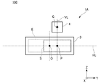
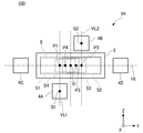
- FIG. 1 is a schematic view showing the configuration of a vehicle lamp 100 provided with a transmissive lighting device 1A.
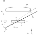
- FIG. 2 is a schematic view showing the configuration of a vehicle lamp 100 provided with a reflective lighting device 1B.
- the XYZ Cartesian coordinate system is set, the X-axis direction is the front-rear direction of the lighting devices 1A and 1B (vehicle lighting equipment 100), and the Y-axis direction is the lighting devices 1A and 1B (vehicle lighting equipment 100).
- the left-right direction and the Z-axis direction of the above are shown as the up-down directions of the lighting devices 1A and 1B (vehicle lighting equipment 100), respectively.
- the lighting device 1A of the present embodiment is a vehicle headlight that irradiates the illumination light W toward the front (+ X-axis direction) of the vehicle as the vehicle lighting tool 100 mounted on the vehicle.
- the present invention is applied to (headlamp).
- the illuminating device 1A includes a projection lens 200 that projects the illumination light WL toward the front of the vehicle, and is housed inside a lamp body (not shown) together with the projection lens 200. Consists of.
- the illumination device 1A is a transmission type wavelength conversion member 3A that emits a laser light source 2 that emits a laser beam BL that becomes excitation light and a fluorescent light YL that is excited by irradiation of the laser beam BL and has a wavelength conversion.
- a laser light scanning mechanism 4 that scans the laser light BL irradiated toward the wavelength conversion member 3A, and a reflector 5 that reflects the laser light BL scanned by the laser light scanning mechanism 4 toward the wavelength conversion member 3A. Is roughly equipped.
- the laser light source 2 is composed of a laser diode (LD) that emits, for example, a blue laser light (emission wavelength is about 450 nm) as the laser light BL.
- LD laser diode
- an LD that emits ultraviolet laser light may be used as the laser light BL.
- the wavelength conversion member 3A is composed of a plate-shaped phosphor plate containing yellow phosphor particles that are excited by irradiation with laser light BL and emit yellow light as fluorescent light YL.
- the wavelength conversion member 3A for example, a member containing phosphor particles made of a composite (sintered body) of YAG and alumina Al2O3 into which an activator such as cerium Ce has been introduced is used. ..
- the wavelength conversion member 3A may include a diffusing agent in order to control the light distribution characteristics of the illumination light WL emitted from the illumination device 1A.
- the laser light scanning mechanism 4 includes a MEMS mirror arranged in an optical path between the laser light source 2 and the wavelength conversion member 3A.
- the MEMS mirror is a movable mirror using MEMS technology, and controls the scanning direction and scanning speed of the laser beam BL scanned in the plane of the wavelength conversion member 3A.
- the reflector 5 is composed of a plane mirror arranged in an optical path between the wavelength conversion member 3A and the laser light scanning mechanism 4.
- the reflector 5 reflects the laser beam BL reflected by the MEMS mirror toward the back surface of the wavelength conversion member 3A.
- a part of the laser light (blue light) BL irradiated toward the back surface of the wavelength conversion member 3A is transmitted through the wavelength conversion member 3A while being diffused, and is irradiated by the laser light BL.
- fluorescent light (yellow light) YL is emitted
- the illumination light (white light) WL is emitted from the projection lens 200 in front by mixing these blue light and yellow light. It is possible to emit light toward.
- the lighting device 1B of the present embodiment illuminates, for example, toward the front of the vehicle (+ X-axis direction) as the vehicle lighting tool 100 mounted on the vehicle, similarly to the lighting device 1A.
- the present invention is applied to a vehicle headlamp that irradiates light W.
- the lighting device 1B constitutes the vehicle lighting tool 100 by being housed inside a lighting body (not shown) together with a projection lens 200 that projects the illumination light WL toward the front of the vehicle.
- the illumination device 1B includes a laser light source 2 that emits a laser beam BL that becomes excitation light, and a reflection type wavelength conversion member 3B that emits fluorescent light YL that is excited by irradiation of the laser beam BL and has a wavelength conversion.
- a laser light scanning mechanism 4 that scans the laser light BL irradiated toward the wavelength conversion member 3B, and a reflector 5 that reflects the laser light BL scanned by the laser light scanning mechanism 4 toward the wavelength conversion member 3B. Is roughly equipped.
- the lighting device 1B includes a reflection type wavelength conversion member 3B instead of the transmission type wavelength conversion member 3A, and the laser light source 2 and the laser light scanning mechanism 4 are arranged according to the arrangement of the wavelength conversion member 3B. It has basically the same configuration as the above-mentioned lighting device 1A except that the arrangement of the reflector 5 is changed.
- the wavelength conversion member 3B has a configuration in which the reflector 6 is arranged on the back surface side of the phosphor plate constituting the wavelength conversion member 3A.
- the reflector 6 reflects the laser light BL incident from the front side of the wavelength conversion member 3B and the fluorescent light YL excited in the wavelength conversion member 3B toward the front side of the wavelength conversion member 3B.
- the illumination device 1B of the present embodiment a part of the laser light (blue light) BL irradiated toward the front surface of the wavelength conversion member 3B is reflected by the wavelength conversion member 3B while being diffused, and the laser light BL is irradiated.
- the illumination light (white light) WL is projected forward by mixing the blue light and the yellow light while emitting the fluorescent light (yellow light) YL. It is possible to emit light toward the lens 200.
- the vehicle lighting equipment 100 of the present embodiment by providing the above-mentioned lighting devices 1A and 1B, as a passing beam (low beam), an illumination light WL that forms a low beam light distribution pattern including a cut-off line at the upper end, and traveling.
- the illumination light WL forming the high beam light distribution pattern above the low beam light distribution pattern can be projected toward the front of the vehicle by the projection lens 200.
- a light distribution variable headlamp that variably controls the light distribution pattern of the illumination light WL projected toward the front of the vehicle by scanning the laser light BL is used. It is also possible.
- an image for drawing is obtained by scanning the laser light BL separately from the illumination light WL projected toward the front of the vehicle. It is also possible to project the drawing light forming the light distribution pattern) toward the road surface by the projection lens 200.
- the incident angle of the laser light BL scanned by the laser light scanning mechanism 4 with respect to the wavelength conversion members 3A and 3B is the wavelength conversion members 3A and 3B.
- the laser beam BL is set at an angle that does not directly incident on the projection lens 200 when the lens is damaged, missing, or dropped off.
- the laser light scanned by the laser light scanning mechanism 4 is scanned even if the wavelength conversion members 3A and 3B are defective, damaged, or dropped. It is possible to prevent the BL from being directly emitted to the outside through the projection lens 200.
- the laser light source 2 and the laser scanning mechanism 4 have the upper side and the lower side of the light distribution pattern sandwiching the wavelength conversion member 3. It is located at a position corresponding to at least one of them, and is arranged so as to be offset from one side corresponding to the left side of the light distribution pattern and the other side corresponding to the right side of the light distribution pattern.
- the laser light source 2 and the laser scanning mechanism 4 of the illumination devices 1A and 1B of the present embodiment correspond to one side corresponding to the left side of the light distribution pattern and the other corresponding to the right side of the light distribution pattern with respect to the center of the wavelength conversion member. It is arranged on either side of the wavelength conversion member 3 so as to be offset from the center of the wavelength conversion member 3.
- the center P of the scanning range S of the laser light BL passes through the center Q of the laser light scanning mechanism 4. It is located at the intersection of the vertical line VL corresponding to the vertical direction and the horizontal line HL corresponding to the horizontal direction of the light distribution pattern passing through the center O of the laser beam irradiation region E.
- the laser light source 2, the laser light scanning mechanism 4, and the reflector 5 are arranged in accordance with the arrangement of the transmission type wavelength conversion member 3A and the reflection type wavelength conversion member 3B described above. It has basically the same configuration except that it has been changed.
- the transmission type wavelength conversion member 3A and the reflection type wavelength conversion member 3B are collectively treated as the "wavelength conversion member 3", and the transmission type illumination device 1A is referred to in FIGS. 3 and 4.
- the explanation will be given by way of exemplifying the present invention, the present invention can be similarly applied to the reflective lighting device 1B.
- FIG. 3 is a front view of the lighting device 1A showing the positional relationship between the center O of the laser light irradiation region E and the center P of the scanning range S of the laser light BL.
- FIG. 4 is a top view of the lighting device 1A showing the positional relationship between the center O of the laser light irradiation region E and the center P of the scanning range S of the laser light BL.
- the wavelength conversion member 3 has a rectangular shape in a plan view (X-axis direction view) corresponding to a light distribution pattern corresponding to the scanning range S of the laser light BL.
- the longitudinal direction of the laser irradiation region E corresponds to the left-right direction (Y-axis direction) of the light distribution pattern
- the lateral direction of the laser irradiation region E corresponds to the vertical direction (Z-axis direction) of the light distribution pattern. ..
- the laser light irradiation region E has a so-called horizontally long shape in which the width corresponding to the left-right direction of the light distribution pattern is longer than the height corresponding to the vertical direction of the light distribution pattern when the wavelength conversion member 3 is viewed in a plan view.
- the light distribution pattern when the illumination light WL emitted toward the front of the vehicle lighting tool 100 is projected onto the virtual vertical screen facing the vehicle lighting tool 100 is also horizontally long.
- the laser scanning mechanism 4 is arranged and controlled so that the scanning range S of the laser beam L with respect to the laser scanning region E of the wavelength conversion member 3 is also horizontally long.
- the laser scanning mechanism 4 is located on the upper side or the lower side (in the present embodiment) of the light distribution pattern sandwiching the horizontally long wavelength conversion member 3 in the lateral direction. It is in the position corresponding to the upper side).
- the incident angle of the laser light BL incident on the center O of the laser light irradiation region E is defined as ⁇ a.
- FIG. 5 shows a case where the laser scanning mechanism 4 is located at a position corresponding to the left side or the right side (left side in the present embodiment) which is the longitudinal direction of the light distribution pattern sandwiching the wavelength conversion member 3.
- the incident angle of the laser light BL incident on the center O of the laser light irradiation region E is set to ⁇ b.
- the MEMS mirror of the laser scanning mechanism 4 is operated at the same deflection angle. Assuming, the incident angle ⁇ a shown in FIG. 4 can be made smaller than the incident angle ⁇ b shown in FIG.
- the laser scanning mechanism 4 when the above-mentioned laser scanning mechanism 4 is located at a position corresponding to the upper side or the lower side of the light distribution pattern sandwiching the wavelength conversion member 3 in the lateral direction, the laser light BL irradiated to the wavelength conversion member 3 It is possible to reduce the spot size. This makes it possible to increase the resolution of the light distribution pattern formed by the ADB described above.
- the upper laser light scanning mechanism 4 corresponds to one side corresponding to the left side in the longitudinal direction of the light distribution pattern and the other corresponding to the right side in the longitudinal direction of the light distribution pattern.
- ⁇ c be the angle of incidence with respect to the normal line (X-axis) of 3, and let be the incident vector Vc of the laser beam BL above it.
- FIG. 7 shows a case where the laser light scanning mechanism 4 is located on the upper center side of the wavelength conversion member 3.
- the incident angle of the upper laser light BL incident on the right end of the laser light irradiation region E with respect to the normal line (X axis) of the wavelength conversion member 3 is ⁇ d, and the incident vector of the upper laser light BL. Let it be Vd.
- the MEMS mirror of the laser scanning mechanism 4 is operated at the same deflection angle. Assuming that, the incident angle ⁇ c shown in FIG. 6 can be made smaller than the incident angle ⁇ d shown in FIG. 7.
- the speed at which the MEMS mirror is reciprocally swung is determined in the laser light irradiation region.
- the maximum is near the center of E, and the minimum is near the left and right ends of the laser beam irradiation region E.
- the luminous intensity distribution in the plane of the laser light irradiation region E becomes relatively high in the vicinity of the left and right ends of the laser light irradiation region E where the speed becomes low.
- a correction mirror can be used as a means for optically correcting this luminous intensity distribution.
- the correction mirror can flatten the luminous intensity distribution by optically stretching the vicinity of the left and right ends of the laser beam irradiation region E where the brightness becomes high.
- the spot size becomes large near both the left and right ends of the laser beam irradiation region E.
- the wider the scanning range S of the laser light BL the more correction is required near the left and right ends of the laser light irradiation area E, and the larger the spot size becomes.
- the upper laser scanning mechanism 4 shifts the center P of the scanning range S of the upper laser light BL described above to the right with respect to the center O of the laser light irradiation region E, thereby shifting the laser light irradiation region E.
- the incident angle ⁇ c near the left and right ends of the light intensity distribution in the plane can be reduced.
- the scanning range S of the upper laser light BL can be reduced, and the spot size becomes large near the left and right ends of the laser light irradiation area E. It is possible to prevent it from growing. This makes it possible to increase the resolution of the light distribution pattern formed by the ADB described above.
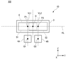
- FIG. 8 is a schematic view showing the configuration of the vehicle lamp 100 provided with the lighting device 1C.
- FIG. 9 shows the positional relationship between the center O of the laser light irradiation region E of the lighting device 1C, the center P1 of the scanning range S1 of the laser light BL1 on the lower left side, and the center P2 of the scanning range S2 of the laser light BL2 on the upper right side. It is a front view which shows.
- the same parts as those of the lighting devices 1A and 1B will be omitted and the same reference numerals will be given in the drawings.
- the transmission type wavelength conversion member 3A and the reflection type wavelength conversion member 3B shall be collectively treated as the "wavelength conversion member 3", and the transmission type illumination device 1C is illustrated in FIGS. Although the description will be given, the present invention can be similarly applied to a reflective lighting device.
- the vehicle lighting equipment 100 provided with the lighting device 1C of the present embodiment is located at a position corresponding to the lower side of the light distribution pattern sandwiching the wavelength conversion member 3 in the lateral direction.
- the laser light source 3A and the laser scanning mechanism 4A on the lower left side which are arranged so as to be shifted to the left side (one side) which is the longitudinal direction of the light distribution pattern, and the light distribution pattern sandwiching the wavelength conversion member 3 in the lateral direction. It has a laser light source 3B and a laser scanning mechanism 4B on the upper right side, which are located at positions corresponding to the upper side and are arranged so as to be shifted to the right side (the other side) which is the longitudinal direction of the light distribution pattern.
- the laser light source 3A and the laser scanning mechanism 4A of the vehicle lamp 100 provided with the lighting device 1C of the present embodiment are shifted to the left side (one side) in the longitudinal direction of the light distribution pattern with respect to the center of the wavelength conversion member 3. Is arranged.
- the laser light source 3B and the laser scanning mechanism 4B of the vehicle lamp 100 provided with the lighting device 1C of the present embodiment are shifted to the right side (the other side) in the longitudinal direction of the light distribution pattern with respect to the center of the wavelength conversion member 3. Is arranged.
- the laser light scanning mechanism 4A on the lower left side scans the laser light BL1 on the lower left side (one side) emitted from the laser light source 2A on the lower left side toward the laser light irradiation region E, thereby causing the laser light BL1 on the lower left side.
- a light distribution pattern corresponding to the scanning range S1 is formed.
- the laser light scanning mechanism 4B on the upper right side scans the laser light BL2 on the upper right side (the other side) emitted from the laser light source 2B on the upper right side toward the laser light irradiation region E, thereby causing the laser light BL2 on the upper right side.
- a light distribution pattern corresponding to the scanning range S2 is formed.
- the light distribution pattern corresponding to the scanning range S1 of the laser light BL1 on the lower left side and the light distribution pattern corresponding to the scanning range S2 of the laser light BL2 on the upper right side are superimposed. It forms one synthetic light distribution pattern.
- the center P1 of the scanning range S1 of the laser light BL1 on the lower left side passes through the center Q1 of the laser light scanning mechanism 4A on the lower left side. It is located at the intersection of the vertical line VL1 corresponding to the vertical direction of the light distribution pattern and the horizontal line HL corresponding to the horizontal direction of the light distribution pattern passing through the center O of the laser light irradiation region E.
- the center P2 of the scanning range S2 of the laser beam BL2 on the upper right side is the vertical line VL2 corresponding to the vertical direction of the light distribution pattern passing through the center Q2 of the laser light scanning mechanism 4B on the upper right side, and the laser beam irradiation. It is located at the intersection with the horizontal line HL corresponding to the left-right direction of the light distribution pattern passing through the center O of the region E.
- P2 is located on the left side and the right side of the center O of the laser beam irradiation region E.
- the angle of incidence with respect to 3 is set to an angle at which the laser beams BL1 and BL2 do not directly incident on the projection lens 200 when the wavelength conversion member 3 is damaged, missing, or dropped off.
- the laser light scanning mechanisms 4A and 4B on the lower left side and the upper right side scan. It is possible to prevent the laser beams BL1 and BL2 on the lower left side and the upper right side from being directly emitted to the outside through the projection lens 200.
- the laser light scanning mechanisms 4A and 4B on the lower left side and the upper right side described above correspond to the lower side and the upper side in the lateral direction of the light distribution pattern sandwiching the wavelength conversion member 3.
- the light distribution pattern is arranged so as to be offset from one side corresponding to the left side in the longitudinal direction of the light distribution pattern and the other side corresponding to the right side in the longitudinal direction of the light distribution pattern.
- the laser light scanning mechanisms 4A and 4B of the illumination device 1C of the present embodiment have one side corresponding to the left side in the longitudinal direction of the light distribution pattern and the other side corresponding to the right side in the longitudinal direction of the light distribution pattern. They are arranged so as to be offset from the center of the wavelength conversion member 3.
- the center P2 is located on the left side and the right side of the center O of the laser beam irradiation region E.
- the vehicle lamp 100 provided with the lighting device 1C of the present embodiment it is possible to reduce the spot size of the laser beams BL1 and BL2 on the lower left side and the upper right side irradiated on the wavelength conversion member 3. As a result, it is possible to increase the resolution of the light distribution pattern formed by the above-mentioned ADB.
- FIG. 10 is a schematic view showing the configuration of the vehicle lamp 100 provided with the lighting device 1D.
- FIG. 11 shows the positional relationship between the center O of the laser light irradiation region E of the lighting device 1D, the center P1 of the scanning range S1 of the laser light BL1 on the lower left side, and the center P2 of the scanning range S2 of the laser light BL2 on the lower right side. It is a front view which shows.
- the same parts as those of the lighting devices 1A and 1B will be omitted and the same reference numerals will be given in the drawings.
- the transmission type wavelength conversion member 3A and the reflection type wavelength conversion member 3B are collectively treated as the "wavelength conversion member 3", and while exemplifying the transmission type illumination device 1D in FIGS. 10 and 11, the transmission type illumination device 1D is illustrated.
- the present invention can be similarly applied to a reflective lighting device.
- the vehicle lighting equipment 100 provided with the lighting device 1D of the present embodiment is located at a position corresponding to the lower side of the light distribution pattern sandwiching the wavelength conversion member 3 in the lateral direction.
- the laser light source 3A and the laser scanning mechanism 4A on the lower left side which are arranged so as to be shifted to the left side (one side) which is the longitudinal direction of the light distribution pattern, and the right side (the other side) which is the longitudinal direction of the light distribution pattern. It has a laser light source 3B on the lower right side and a laser scanning mechanism 4B arranged in a staggered manner. Other than that, it has basically the same configuration as the vehicle lamp 100 provided with the lighting device 1C.
- the laser light source 3A and the laser scanning mechanism 4A of the vehicle lamp 100 provided with the lighting device 1D of the present embodiment are shifted to the left side (one side) in the longitudinal direction of the light distribution pattern with respect to the center of the wavelength conversion member 3. Is arranged.
- the laser light source 3B and the laser scanning mechanism 4B of the vehicle lamp 100 provided with the lighting device 1D of the present embodiment are shifted to the right side (the other side) in the longitudinal direction of the light distribution pattern with respect to the center of the wavelength conversion member 3. Is arranged.
- the laser light scanning mechanism 4A on the lower left side scans the laser light BL1 on the lower left side (one side) emitted from the laser light source 2A on the lower left side toward the laser light irradiation region E, thereby causing the laser light BL1 on the lower left side.
- a light distribution pattern corresponding to the scanning range S1 is formed.
- the laser light scanning mechanism 4B on the lower right side scans the laser light BL2 on the lower right side (the other side) emitted from the laser light source 2A on the lower right side toward the laser light irradiation region E, thereby causing the laser light BL2 on the lower right side.
- a light distribution pattern corresponding to the scanning range S2 is formed.
- the light distribution pattern corresponding to the scanning range S1 of the laser beam BL1 on the lower left side and the light distribution pattern corresponding to the scanning range S2 of the laser beam BL2 on the lower right side are superimposed. It forms one synthetic light distribution pattern.
- the center P1 of the scanning range S1 of the laser light BL1 on the lower left side passes through the center Q1 of the laser light scanning mechanism 4A on the lower left side. It is located at the intersection of the vertical line VL1 corresponding to the vertical direction of the light distribution pattern and the horizontal line HL corresponding to the horizontal direction of the light distribution pattern passing through the center O of the laser light irradiation region E.
- the center P2 of the scanning range S2 of the laser beam BL2 on the lower right side is the vertical line VL2 corresponding to the vertical direction of the light distribution pattern passing through the center Q2 of the laser light scanning mechanism 4B on the lower right side, and the laser beam irradiation. It is located at the intersection with the horizontal line HL corresponding to the left-right direction of the light distribution pattern passing through the center O of the region E.
- P2 is located on the left side and the right side of the center O of the laser beam irradiation region E.
- the wavelength conversion member of the laser light BL1 and BL2 on the lower left side and the lower right side scanned by the laser light scanning mechanisms 4A and 4B on the lower left side and the lower right side described above.
- the angle of incidence with respect to 3 is set to an angle at which the laser beams BL1 and BL2 do not directly incident on the projection lens 200 when the wavelength conversion member 3 is damaged, missing, or dropped off.
- the laser light scanning mechanisms 4A and 4B on the lower left side and the lower right side scan. It is possible to prevent the laser beams BL1 and BL2 on the lower left side and the lower right side from being directly emitted to the outside through the projection lens 200.
- the positions of the laser light scanning mechanisms 4A and 4B on the lower left side and the lower right side described above correspond to the lower side of the light distribution pattern sandwiching the wavelength conversion member 3 in the lateral direction. And, they are arranged so as to be offset from one side corresponding to the left side in the longitudinal direction of the light distribution pattern and the other side corresponding to the right side in the longitudinal direction of the light distribution pattern.
- the laser light scanning mechanisms 4A and 4B of the illumination device 1D of the present embodiment have one side corresponding to the left side in the longitudinal direction of the light distribution pattern and the other side corresponding to the right side in the longitudinal direction of the light distribution pattern. They are arranged so as to be offset from the center of the wavelength conversion member 3.
- the center P2 is located on the left side and the right side of the center O of the laser beam irradiation region E.
- the vehicle lamp 100 provided with the lighting device 1D of the present embodiment it is possible to reduce the spot size of the laser beams BL1 and BL2 on the lower left side and the lower right side irradiated on the wavelength conversion member 3. As a result, it is possible to increase the resolution of the light distribution pattern formed by the above-mentioned ADB.
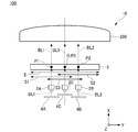
- FIG. 12 is a schematic view showing the configuration of the vehicle lamp 100 provided with the lighting device 1E.
- FIG. 11 shows the center O of the laser light irradiation region E of the lighting device 1E, the center P1 of the scanning range S1 of the laser light BL1 on the lower left side, the center P2 of the scanning range S2 of the laser light BL2 on the lower right side, and the upper center side.
- It is a front view which shows the positional relationship with the center P3 of the scanning range S3 of a laser beam BL3.
- the same parts as those of the lighting device 1D will be omitted and the same reference numerals will be given in the drawings.
- the transmission type wavelength conversion member 3A and the reflection type wavelength conversion member 3B are collectively treated as the "wavelength conversion member 3", and while exemplifying the transmission type lighting device 1E in FIGS. 12 and 13, the transmission type lighting device 1E is illustrated.
- the present invention can be similarly applied to a reflective lighting device.
- the vehicle lamp 100 provided with the lighting device 1E of the present embodiment has a short light distribution pattern sandwiching the wavelength conversion member 3 in addition to the configuration of the lighting device 1D. It has a laser light source 2C and a laser scanning mechanism 4C on the upper center side additionally arranged on either the upper side (one side) or the lower side (the other side) (upper side in this embodiment) in the direction. ..
- the laser light scanning mechanism 4C on the upper center side scans the laser light BL3 on the upper center side (additional) emitted from the laser light source 2C on the upper center side toward the laser light irradiation region E, thereby scanning the laser light BL3 on the upper center side.
- a light distribution pattern corresponding to the scanning range S3 of the laser light BL3 is formed.
- the light distribution pattern corresponding to the scanning range S1 of the laser beam BL1 on the lower left side the light distribution pattern corresponding to the scanning range S2 of the laser light BL2 on the lower right side, and the light distribution pattern on the upper center side.
- One synthetic light distribution pattern is formed by superimposing the laser light BL3 with the light distribution pattern according to the scanning range S3.
- the center P3 of the scanning range S3 of the laser light BL3 on the upper center side is the center Q3 of the laser light scanning mechanism 4C on the upper center side. It is located at the intersection of the vertical line VL3 corresponding to the vertical direction of the light distribution pattern passing through the laser beam and the horizontal line HL corresponding to the horizontal direction of the light distribution pattern passing through the center O of the laser beam irradiation region E.
- the center P3 of the scanning range S3 of the laser beam BL3 on the upper center side coincides with the center O of the laser beam irradiation region E.
- the lower left side, the lower right side, and the upper center side scanned by the laser light scanning mechanisms 4A, 4B, and 4C on the lower left side, the lower right side, and the upper center side described above.
- the angle of incidence of the laser beams BL1, BL2, and BL3 on the wavelength conversion member 3 is the angle at which the laser beams BL1, BL2, and BL3 do not directly incident on the projection lens 200 when the wavelength conversion member 3 is damaged, missing, or dropped. Is set to.
- the laser light scanning mechanism 4A on the lower left side, the lower right side, and the upper center side. , 4B, 4C can prevent the laser beams BL1, BL2, and BL3 on the lower left side, the lower right side, and the upper center side from being directly emitted to the outside through the projection lens 200.
- the positions of the laser light scanning mechanisms 4A and 4B on the lower left side and the lower right side described above correspond to the lower side of the light distribution pattern sandwiching the wavelength conversion member 3 in the lateral direction.
- the laser light scanning mechanism 4C on the central side of the lower upper portion is located at a position corresponding to the upper side of the light distribution pattern sandwiching the wavelength conversion member 3 in the lateral direction.
- the laser light scanning mechanisms 4A and 4B on the lower left side and the lower right side are on one side corresponding to the left side in the longitudinal direction of the light distribution pattern and the other side corresponding to the right side in the longitudinal direction of the light distribution pattern. Each is staggered.
- the laser light scanning mechanisms 4A and 4B of the illumination device 1E of the present embodiment have one side corresponding to the left side in the longitudinal direction of the light distribution pattern and the other side corresponding to the right side in the longitudinal direction of the light distribution pattern. They are arranged so as to be offset from the center of the wavelength conversion member 3.
- the center P2 is located on the left side and the right side of the center O of the laser beam irradiation region E.
- the spot sizes of the laser beams BL1, BL2, and BL3 on the lower left side, the lower right side, and the upper center side irradiated to the wavelength conversion member 3 are reduced. Is possible. As a result, it is possible to increase the resolution of the light distribution pattern formed by the above-mentioned ADB.
- FIG. 14 is a schematic view showing the configuration of the vehicle lamp 100 provided with the lighting device 1F.
- FIG. 15 shows the center O of the laser light irradiation region E of the lighting device 1F, the center P1 of the scanning range S1 of the laser light BL1 on the lower left side, the center P2 of the scanning range S2 of the laser light BL2 on the upper right side, and the laser light on the right side.
- It is a front view which shows the positional relationship with the center P3 of the scanning range S3 of BL3.
- the same parts as those of the lighting device 1C will be omitted and the same reference numerals will be given in the drawings.
- the transmission type wavelength conversion member 3A and the reflection type wavelength conversion member 3B are collectively treated as the "wavelength conversion member 3", and while exemplifying the transmission type lighting device 1F in FIGS. 14 and 15, the transmission type lighting device 1F is illustrated.
- the present invention can be similarly applied to a reflective lighting device.
- the vehicle lamp 100 provided with the lighting device 1F of the present embodiment is added to the configuration of the lighting device 1C in the longitudinal direction of the light distribution pattern sandwiching the wavelength conversion member 3. It has a laser light source 2C and a laser scanning mechanism 4C on the right side additionally arranged on either the left side (one side) or the right side (the other side) (the right side in this embodiment).
- the laser light scanning mechanism 4C on the right side scans the laser light BL3 on the right side (additional) radiated from the laser light source 2C on the right side toward the laser light irradiation region E, so that the scanning range S3 of the laser light BL3 on the right side is reached. Form the corresponding light distribution pattern.
- the light distribution pattern corresponding to the scanning range S1 of the laser light BL1 on the lower left side the light distribution pattern corresponding to the scanning range S2 of the laser light BL2 on the upper right side, and the laser light on the right side.
- One synthetic light distribution pattern is formed by superimposing the light distribution pattern according to the scanning range S3 of BL3.
- the center P3 of the scanning range S3 of the laser light BL3 on the right side is at a position coincided with the center O of the laser light irradiation region E. ..
- the angle of incidence of BL2 and BL3 on the wavelength conversion member 3 is set to an angle at which the laser beams BL1, BL2 and BL3 do not directly incident on the projection lens 200 when the wavelength conversion member 3 is damaged, missing or dropped. There is.
- the laser light scanning mechanisms 4A, 4B on the lower left side, the upper right side, and the right side It is possible to prevent the lower left side, upper right side and right side laser beams BL1, BL2 and BL3 scanned by 4C from being directly emitted to the outside through the projection lens 200.
- the laser light scanning mechanisms 4A and 4B on the lower left side and the upper right side described above correspond to the lower side and the upper side in the lateral direction of the light distribution pattern sandwiching the wavelength conversion member 3.
- the light distribution pattern is arranged so as to be offset from one side corresponding to the left side in the longitudinal direction of the light distribution pattern and the other side corresponding to the right side in the longitudinal direction of the light distribution pattern.
- the laser light scanning mechanisms 4A and 4B of the illumination device 1F of the present embodiment have one side corresponding to the left side in the longitudinal direction of the light distribution pattern and the other side corresponding to the right side in the longitudinal direction of the light distribution pattern. They are arranged so as to be offset from the center of the wavelength conversion member 3.
- the center P1 of the scanning range S1 of the laser light BL1 on the lower left side and the scanning range S2 of the laser light BL2 on the upper right side The center P2 is located on the left side and the right side of the center O of the laser beam irradiation region E.
- the vehicle lamp 100 provided with the lighting device 1F of the present embodiment it is possible to reduce the spot size of the laser beams BL1 and BL2 on the lower left side and the upper right side irradiated on the wavelength conversion member 3. As a result, it is possible to increase the resolution of the light distribution pattern formed by the above-mentioned ADB.
- the wavelength conversion member 3 is irradiated rather than the scanning ranges S1 and S2 in the left-right direction of the laser beams BL1 and BL2 on the lower left side and the upper right side to be irradiated to the wavelength conversion member 3 described above.
- the scanning range S3 in the left-right direction of the laser beam BL3 on the right side the spot size of the laser beam BL3 on the right side can be reduced.
- the lighting device 1F of the present embodiment it is easier to spatially arrange the laser light source 2C and the laser scanning mechanism 4C to be additionally arranged than the lighting device 1E.
- FIG. 16 is a schematic view showing the configuration of the vehicle lamp 100 provided with the lighting device 1G.
- FIG. 17 shows the center O of the laser light irradiation region E of the lighting device 1C, the center P1 of the scanning range S1 of the laser light BL1 on the lower left side, the center P2 of the scanning range S2 of the laser light BL2 on the lower right side, and the laser on the upper left side.
- It is a front view which shows the positional relationship with the center P3 of the scanning range S3 of the light BL3, and the center P4 of the scanning range S4 of the laser light BL4 on the upper right side.
- the same parts as those of the lighting device 1D will be omitted and the same reference numerals will be given in the drawings.
- the transmission type wavelength conversion member 3A and the reflection type wavelength conversion member 3B shall be collectively treated as the "wavelength conversion member 3", and the transmission type illumination device 1G is illustrated in FIGS. 16 and 17 and the same.
- the present invention can be similarly applied to a reflective lighting device.
- the vehicle lighting tool 100 provided with the lighting device 1G of the present embodiment has a short light distribution pattern sandwiching the wavelength conversion member 3 in addition to the configuration of the lighting device 1D.
- the laser light source 3C and the laser scanning mechanism 4C on the upper left side which are located at positions corresponding to the upper side of the light distribution pattern and are shifted to the left side (one side) which is the longitudinal direction of the light distribution pattern, and the light distribution pattern. It has a laser light source 3D on the upper right side and a laser scanning mechanism 4D arranged so as to be offset to the right side (the other side) in the longitudinal direction.
- it has basically the same configuration as the lighting device 100 for a vehicle equipped with the lighting device 1D.
- the laser light source 3C and the laser scanning mechanism 4C of the vehicle lamp 100 provided with the lighting device 1G of the present embodiment are shifted to the left side (one side) in the longitudinal direction of the light distribution pattern with respect to the center of the wavelength conversion member 3. Is arranged.
- the laser light source 3D and the laser scanning mechanism 4D of the vehicle lamp 100 provided with the lighting device 1G of the present embodiment are shifted to the right side (the other side) in the longitudinal direction of the light distribution pattern with respect to the center of the wavelength conversion member 3. Is arranged.
- the laser light scanning mechanism 4C on the upper left side scans the laser light BL3 on the upper left side (one side) emitted from the laser light source 2C on the upper left side toward the laser light irradiation region E, thereby causing the laser light BL3 on the upper left side.
- a light distribution pattern corresponding to the scanning range S3 is formed.
- the laser light scanning mechanism 4D on the upper right side scans the laser light BL2 on the upper right side (the other side) emitted from the laser light source 2D on the upper right side toward the laser light irradiation region E, thereby causing the laser light BL2 on the upper right side.
- a light distribution pattern corresponding to the scanning range S2 is formed.
- the light distribution pattern corresponding to the scanning range S1 of the laser beam BL1 on the lower left side the light distribution pattern corresponding to the scanning range S2 of the laser light BL2 on the lower right side, and the laser on the upper left side.
- One synthetic light distribution pattern is formed by superimposing the light distribution pattern corresponding to the scanning range S3 of the light BL3 and the light distribution pattern corresponding to the scanning range S4 of the laser light BL4 on the upper right side.
- the center P3 of the scanning range S3 of the laser light BL3 on the upper left side passes through the center Q3 of the laser light scanning mechanism 4C on the upper left side. It is located at the intersection of the vertical line VL3 corresponding to the vertical direction of the light distribution pattern and the horizontal line HL corresponding to the horizontal direction of the light distribution pattern passing through the center O of the laser light irradiation region E.
- the center P4 of the scanning range S4 of the laser beam BL4 on the upper right side is the vertical line VL4 corresponding to the vertical direction of the light distribution pattern passing through the center Q4 of the laser light scanning mechanism 4D on the upper right side, and the laser beam irradiation. It is located at the intersection with the horizontal line HL corresponding to the left-right direction of the light distribution pattern passing through the center O of the region E.
- P4 is located on the left side and the right side of the center O of the laser beam irradiation region E.
- the wavelength conversion members of the upper left and upper right laser beams BL3 and BL4 scanned by the above-mentioned upper left and upper right laser light scanning mechanisms 4C and 4D.
- the angle of incidence with respect to 3 is set to an angle at which the laser beams BL3 and BL4 do not directly incident on the projection lens 200 when the wavelength conversion member 3 is damaged, missing, or dropped off.
- the laser light scanning mechanisms 4C and 4D on the upper left side and the upper right side scan. It is possible to prevent the laser beams BL3 and BL4 on the upper left side and the upper right side from being directly emitted to the outside through the projection lens 200.
- the above-mentioned upper left side and upper right side laser light scanning mechanisms 4C and 4D are positioned at positions corresponding to the upper side of the light distribution pattern sandwiching the wavelength conversion member 3 in the lateral direction. Moreover, they are arranged so as to be offset from one side corresponding to the left side in the longitudinal direction of the light distribution pattern and the other side corresponding to the right side in the longitudinal direction of the light distribution pattern.
- the laser light scanning mechanisms 4C and 4D of the illumination device 1G of the present embodiment have one side corresponding to the left side in the longitudinal direction of the light distribution pattern and the other side corresponding to the right side in the longitudinal direction of the light distribution pattern. They are arranged so as to be offset from the center of the wavelength conversion member 3.
- the center P4 is located on the left side and the right side of the center O of the laser beam irradiation region E.
- the vehicle lamp 100 provided with the lighting device 1G of the present embodiment it is possible to reduce the spot size of the laser beams BL3 and BL4 on the upper left side and the upper right side irradiated on the wavelength conversion member 3. As a result, it is possible to increase the resolution of the light distribution pattern formed by the above-mentioned ADB.
- FIG. 18 is a schematic view showing the configuration of the vehicle lamp 100 provided with the lighting device 1H.
- FIG. 19 shows the center O of the laser light irradiation region E of the illuminating device 1H, the center P1 of the scanning range S1 of the laser light BL1 on the lower left side, the center P2 of the scanning range S2 of the laser light BL2 on the upper right side, and the laser light on the left side.
- It is a front view which shows the positional relationship with the center P3 of the scanning range S3 of BL3, and the center P4 of the scanning range S4 of the laser light BL4 on the right side.
- the same parts as those of the lighting device 1C will be omitted and the same reference numerals will be given in the drawings.
- the transmission type wavelength conversion member 3A and the reflection type wavelength conversion member 3B are collectively treated as the "wavelength conversion member 3", and while exemplifying the transmission type lighting device 1F in FIGS. 18 and 19, the transmission type lighting device 1F is illustrated.
- the present invention can be similarly applied to a reflective lighting device.
- the vehicle lighting tool 100 provided with the lighting device 1H of the present embodiment is added to the configuration of the lighting device 1C in the longitudinal direction of the light distribution pattern sandwiching the wavelength conversion member 3.
- the laser light scanning mechanism 4C on the left side scans the laser light BL3 on the left side (additional) radiated from the laser light source 2C on the left side toward the laser light irradiation region E, so that the scanning range S3 of the laser light BL3 on the left side is reached. Form the corresponding light distribution pattern.
- the laser light scanning mechanism 4D on the right side scans the laser light BL4 on the right side (additional) emitted from the laser light source 2D on the right side toward the laser light irradiation area E, thereby increasing the scanning range S4 of the laser light BL4 on the right side. Form the corresponding light distribution pattern.
- the light distribution pattern corresponding to the scanning range S1 of the laser light BL1 on the lower left side the light distribution pattern corresponding to the scanning range S2 of the laser light BL2 on the upper right side, and the laser light on the left side.
- One synthetic light distribution pattern is formed by superimposing the light distribution pattern corresponding to the scanning range S3 of BL3 and the light distribution pattern corresponding to the scanning range S4 of the laser light BL4 on the right side.
- the center P3 of the scanning range S3 of the laser light BL3 on the left side is on the left side with respect to the center O of the laser light irradiation region E.
- the laser light scanning mechanism 4C is located on the opposite side (right side) to the side where the laser light scanning mechanism 4C is arranged.
- the center P4 of the scanning range S4 of the laser light BL4 on the right side is on the side (left side) opposite to the side where the laser light scanning mechanism 4D on the right side is arranged with respect to the center O of the laser light irradiation region E. positioned.
- the incident angles of the left and right laser beams BL3 and BL4 scanned by the left and right laser light scanning mechanisms 4C and 4D described above with respect to the wavelength conversion member 3 are
- the angle is set so that the laser beams BL3 and BL4 do not directly incident on the projection lens 200.
- the left and right laser light scanning mechanisms 4C and 4D scan the wavelength conversion member 3. It is possible to prevent the left and right laser beams BL3 and BL4 from being directly emitted to the outside through the projection lens 200.
- the centers P3 and P4 of the scanning ranges S3 and S4 of the left and right laser beams BL3 and BL4 described above are the lasers on the left and right sides with respect to the center O of the laser light irradiation region E.
- the optical scanning mechanisms 4C and 4D By locating the optical scanning mechanisms 4C and 4D on the side opposite to the side on which the optical scanning mechanisms 4C and 4D are arranged, it is possible to reduce the spot size of the laser beams BL3 and BL4 irradiated to the wavelength conversion member 3. This makes it possible to increase the resolution of the light distribution pattern formed by the ADB described above.
- the wavelength conversion member 3 is irradiated rather than the scanning ranges S1 and S2 in the left-right direction of the laser beams BL1 and BL2 on the lower left side and the upper right side to be irradiated to the wavelength conversion member 3 described above.
- the scanning ranges S3 and S4 of the left and right laser beams BL3 and BL4 in the left-right direction it is possible to reduce the spot size of the left and right laser beams BL3 and BL4.
- the lighting device 1H of the present embodiment it is easier to spatially arrange the laser light sources 2C and 2D and the laser scanning mechanisms 4C and 4D to be additionally arranged than the above-mentioned lighting device 1G.
- Examples 1-1, 1-2 and Comparative Example 1 Examples 2-1, 2-2 and Comparative Example 2, Examples 3-1, 3-2 and Comparative Example 3, Example 4
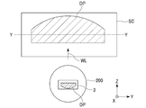
- the illuminating devices of -1, 4-2 and Comparative Example 4 are used to irradiate the illuminating light WL toward the front of the illuminating device with the projection lens 200, and the virtual device faces the illuminating device.
- a simulation was performed in which a light source image of a light distribution pattern DP formed in the plane of the wavelength conversion member 3 was projected onto the vertical screen SC.
- the illumination light WL emitted from each illumination device was adjusted.
- Example 1-1 a transmissive lighting device corresponding to the lighting device 1E was used.
- the lower left side is referred to as "MEMS1”
- the lower right side is referred to as "MEMS2”
- the upper center side is referred to as "MEMS3”.
- the scanning ranges S1 to S3 of the laser beams BL1 to BL3 by MEMS1 to MEMS3 and their centers P1 to P3 are adjusted as shown in Table 1 below, and the light distribution pattern corresponding to the scanning ranges S1 to S3 of the laser beams BL1 to BL3.
- a light distribution pattern DP satisfying the light intensity distribution of the high beam light distribution pattern as shown in FIG. 21 was formed.
- Table 1 for the centers P1 to P3 of each scanning range S1 to S3, the center O of the laser light irradiation region E on the horizontal line HL is set to 0 [mm] with respect to the center O of the laser light irradiation region E.
- the left side is represented as the minus (-) side, and the right side is represented as the plus (+) side.
- the scanning ranges S1 to S3 are scanning widths on the horizontal line HL.
- Tables 2 to 12 shown below are also represented in the same manner.
- Example 1-2 a transmissive lighting device corresponding to the above lighting device 1F was used.
- the lower left side is referred to as "MEMS1”
- the upper right side is referred to as "MEMS2”
- the right side is referred to as "MEMS3”.
- the scanning ranges S1 to S3 of the laser beams BL1 to BL3 and their centers P1 to P3 are adjusted as shown in Table 2 below, and the light distribution patterns corresponding to the scanning ranges S1 to S3 of the laser beams BL1 to BL3 are superposed.
- a light distribution pattern DP that satisfies the light intensity distribution of the high beam light distribution pattern as shown in FIG. 21 was formed.
- Comparative Example 1 of the three MEMS1 to MEMS3 constituting the transmissive lighting device, "MEMS1” is arranged on the left side, “MEMS2" on the right side, and “MEMS3” on the upper side with the wavelength conversion member 3 sandwiched between them.
- the scanning ranges S1 to S3 of the laser beams BL1 to BL3 and their centers P1 to P3 by these three MEMS1 to MEMS3 are adjusted as shown in Table 3 below, and the scanning ranges S1 to S3 of the laser beams BL1 to BL3 are adjusted.
- a light distribution pattern DP satisfying the luminous intensity distribution of the high beam light distribution pattern as shown in FIG. 21 was formed.
- Example 2-1 a reflective lighting device corresponding to the lighting device 1E was used.
- the lower left side is referred to as "MEMS1”
- the lower right side is referred to as "MEMS2”
- the upper center side is referred to as "MEMS3”.
- the scanning ranges S1 to S3 of the laser beams BL1 to BL3 by MEMS1 to MEMS3 and their centers P1 to P3 are adjusted as shown in Table 4 below, and the light distribution pattern corresponding to the scanning ranges S1 to S3 of the laser beams BL1 to BL3.
- a light distribution pattern DP satisfying the light intensity distribution of the high beam light distribution pattern as shown in FIG. 21 was formed.
- Example 2-2 a reflection type lighting device corresponding to the above lighting device 1F was used.
- the lower left side is referred to as "MEMS1”
- the upper right side is referred to as "MEMS2”
- the right side is referred to as "MEMS3”.
- the scanning ranges S1 to S3 of the laser beams BL1 to BL3 and their centers P1 to P3 are adjusted as shown in Table 5 below, and the light distribution patterns corresponding to the scanning ranges S1 to S3 of the laser beams BL1 to BL3 are superposed.
- a light distribution pattern DP that satisfies the light intensity distribution of the high beam light distribution pattern as shown in FIG. 21 was formed.
- Comparative Example 2 of the three MEMS1 to MEMS3 constituting the reflection type lighting device, "MEMS1” is arranged on the left side, “MEMS2" on the right side, and “MEMS3” on the upper side with the wavelength conversion member 3 sandwiched between them.
- the scanning ranges S1 to S3 of the laser beams BL1 to BL3 and their centers P1 to P3 by these three MEMS1 to MEMS3 are adjusted as shown in Table 6 below, and the scanning ranges S1 to S3 of the laser beams BL1 to BL3 are adjusted.
- a light distribution pattern DP satisfying the light intensity distribution of the high beam light distribution pattern as shown in FIG. 21 was formed.
- Example 3-1 a transmissive lighting device corresponding to the lighting device 1G was used.
- the lower left side is "MEMS1”
- the lower right side is “MEMS2”
- the upper left side is “MEMS3”
- the upper part is "MEMS3”
- the right side is designated as "MEMS4"
- the scanning ranges S1 to S4 of the laser beams BL1 to BL4 and their centers P1 to P4 by these four MEMS1 to MEMS4 are adjusted as shown in Table 7 below, and the scanning of the laser beams BL1 to BL4 is performed.
- a light distribution pattern DP satisfying the light intensity distribution of the high beam light distribution pattern as shown in FIG. 21 was formed.
- Example 3-2 a transmissive lighting device corresponding to the lighting device 1H was used.
- the lower left side is “MEMS1”
- the upper right side is “MEMS2”
- the left side is “MEMS3”
- the right side is "MEMS4".
- the scanning ranges S1 to S4 of the laser beams BL1 to BL4 and their centers P1 to P4 by these four MEMS1 to MEMS4 are adjusted as shown in Table 8 below, and the scanning ranges S1 to S4 of the laser beams BL1 to BL4 are adjusted.
- Comparative Example 3 among the four MEMS1 to MEMS4 constituting the transmissive lighting device, "MEMS1” is arranged on the left side, “MEMS2” is arranged on the right side, “MEMS3” is arranged on the upper side, and “MEMS4" is arranged on the lower side.
- the scanning ranges S1 to S4 of the laser beams BL1 to BL4 and their centers P1 to P4 by these four MEMS1 to MEMS4 are adjusted as shown in Table 9 below, and correspond to the scanning ranges S1 to S4 of the laser beams BL1 to BL4.
- a light distribution pattern DP satisfying the luminous intensity distribution of the high beam light distribution pattern as shown in FIG. 21 was formed.
- Example 4-1 a reflection type lighting device corresponding to the lighting device 1G was used.
- the lower left side is "MEMS1”
- the lower right side is “MEMS2”
- the upper left side is “MEMS3”
- the upper part is “MEMS3”
- the right side is designated as "MEMS4"
- the scanning ranges S1 to S4 of the laser beams BL1 to BL4 and their centers P1 to P4 by these four MEMS1 to MEMS4 are adjusted as shown in Table 10 below, and the scanning of the laser beams BL1 to BL4 is performed.
- a light distribution pattern DP satisfying the light intensity distribution of the high beam light distribution pattern as shown in FIG. 21 was formed.
- Example 4-2 a reflective lighting device corresponding to the lighting device 1H was used.
- the lower left side is “MEMS1”
- the upper right side is “MEMS2”
- the left side is “MEMS3”
- the right side is “MEMS4".
- the scanning ranges S1 to S4 of the laser beams BL1 to BL4 and their centers P1 to P4 by these four MEMS1 to MEMS4 are adjusted as shown in Table 11 below, and the scanning ranges S1 to S4 of the laser beams BL1 to BL4 are adjusted.
- Comparative Example 4 among the four MEMS1 to MEMS4 constituting the reflection type lighting device, "MEMS1” is arranged on the left side, “MEMS2” is arranged on the right side, “MEMS3” is arranged on the upper side, and “MEMS4" is arranged on the lower side.
- the scanning ranges S1 to S4 of the laser beams BL1 to BL4 and their centers P1 to P4 by these four MEMS1 to MEMS4 are adjusted as shown in Table 12 below, and correspond to the scanning ranges S1 to S4 of the laser beams BL1 to BL4.
- a light distribution pattern DP satisfying the light intensity distribution of the high beam light distribution pattern as shown in FIG. 21 was formed.
- Examples 1-1, 1-2 and Comparative Example 1, Examples 2-1, 2-2 and Comparative Example 2, Examples 3-1, 3-2 and Comparative Example 3 described above are carried out.
- the incident angles [°] of the laser beams BL1 to BL3 (BL4) incident on the center O of the laser light irradiation region E from the respective MEMS1 to MEMS3 (MEMS4). ] was calculated, and the maximum value (MAX) of the incident angle was obtained.
- the results are summarized in Table 13 below.
- the lighting devices of Examples 1-1, 1-2, 2-1, 2, 3-1, 3-2, 4-1, 4-2 are comparative examples. Compared with the lighting devices 1, 2, 3 and 4, the incident angles and spot sizes of the laser beams BL1 to BL3 (BL4) incident on the center O of the laser beam irradiation region E from each MEMS1 to MEMS3 (MEMS4) are reduced. It is possible.
- the present invention is not necessarily limited to that of the above embodiment, and various modifications can be made without departing from the spirit of the present invention.
- the angle is set so that the laser light BL does not directly incident on the projection lens 200.
- the light-absorbing unit or the light-shielding unit may be configured by arranging an light-absorbing member or a light-shielding member that absorbs or shields the laser light BL.
- the wavelength conversion members 3A and 3B are not necessarily limited to those of the above-described embodiment, and their configurations, materials, and the like can be appropriately selected and used.
- wavelength conversion members 3A and 3B include those in which a molded body of a phosphor plate is bonded or adhered to a substrate, and [2] those in which a phosphor layer (wavelength conversion layer) is formed on a substrate. Can be used.
- a transparent substrate such as a transparent ceramic substrate or a glass substrate can be used.
- a reflection substrate having a reflection film formed on the surface of a ceramic substrate, a glass substrate, or the like can be used.
- a single crystal phosphor, a phosphor ceramic, a phosphor-dispersed glass, a phosphor-dispersed resin sheet, or the like can be used.
- the adhesive for example, a transparent adhesive is used among organic adhesives, inorganic adhesives and the like.
- a ceramic binder, a glass binder, or a resin binder in which phosphor particles are dispersed is placed on a substrate by using a dispensing method, a rotary coating method, a printing method, a spray method, or the like. It is possible to use the one coated in.
- the phosphor particles for example, those obtained by granulating an oxide phosphor, a nitride phosphor, an oxynitride phosphor, a sulfide phosphor, a fluoride phosphor, or the like can be used.
- the thickness of the phosphor layer and the particle size (D50) of the phosphor particles are not particularly limited and can be set arbitrarily.
- a transparent protective layer may be further provided on the phosphor layer.
- an inorganic substance such as glass or ceramic, a silicone resin, an epoxy resin, or the like can be used.
- a piezoelectric type, electrostatic type, or electromagnetic type MEMS mirror can be used. Further, as the MEMS mirror, since the laser beam BL is scanned in the plane of the wavelength conversion members 3A and 3B, two 2-axis type mirrors or 2-axis type mirrors can be used.
- examples of the piezoelectric type 2-axis type include a 1-axis resonance / 1-axis non-resonant type, a 2-axis resonance type, and a 2-axis non-resonance type.
- the non-resonant axis and the resonance axis may be assigned to either the X-axis or the Y-axis in the plane of the wavelength conversion members 3A and 3B.
- the reflector 5 is not limited to the plane mirror described above, but a curved mirror that corrects the distortion of the laser beam BL reflected toward the wavelength conversion members 3A and 3B can also be used. It is also possible to arrange the distortion correction lens between the reflector 5 and the wavelength conversion members 3A and 3B.
- the projection lens 200 is not limited to a single lens, but a combination of a plurality of lenses (group lens) may be used. Further, the lens is not limited to the spherical type, and an aspherical type may be used.
- the lighting device to which the present invention is applied is suitably used for the above-mentioned vehicle lighting equipment, it can be widely applied to applications other than vehicle lighting equipment.
Landscapes
- Engineering & Computer Science (AREA)
- General Engineering & Computer Science (AREA)
- Physics & Mathematics (AREA)
- Optics & Photonics (AREA)
- Non-Portable Lighting Devices Or Systems Thereof (AREA)
- Lighting Device Outwards From Vehicle And Optical Signal (AREA)
Abstract
In this illumination device, the angle at which a laser beam (BL) moved by a laser beam moving mechanism (4) is incident on a wavelength conversion member (3) is set to an angle such that the laser beam (BL) is not incident directly on a projection lens (200) when the wavelength conversion member (3) is damaged or lacking or falls out; and a laser light source (2) and the laser beam moving mechanism (4) are positioned so as to correspond to an upper side and/or a lower side of a light distribution pattern across the wavelength conversion member (3) and are shifted to one side corresponding to the left side of the light distribution pattern or to the other side corresponding to the right side of the light distribution pattern.
Description
本発明は、照明装置、並びにそのような照明装置を備えた車両用灯具に関する。
本願は、2020年1月30日に出願された日本国特願2020-013645号に基づき優先権を主張し、その内容をここに援用する。 The present invention relates to a luminaire and a vehicle lamp equipped with such a luminaire.
The present application claims priority based on Japanese Patent Application No. 2020-013645 filed on January 30, 2020, the contents of which are incorporated herein by reference.
近年、高輝度且つ高出力な光が得られるレーザーダイオード(LD)などのレーザー光源を用いて、このレーザー光源が発するレーザー光を蛍光体プレート(波長変換部材)に照射することによって、照明光を得ることが行われている。
In recent years, using a laser light source such as a laser diode (LD) that can obtain high-brightness and high-output light, the laser light emitted by this laser light source is irradiated to a phosphor plate (wavelength conversion member) to emit illumination light. What is being gained is being done.
このような照明装置では、青色レーザー光を出射するレーザー光源と、この青色レーザー光(励起光)に励起されて波長変換された黄色光(蛍光光)を発する蛍光体プレートとを組み合わせて、これら青色光と黄色光との混色により白色光(照明光)を得ることが可能となっている。
In such a lighting device, a laser light source that emits blue laser light and a phosphor plate that emits yellow light (fluorescent light) that is excited by the blue laser light (excitation light) and whose wavelength is converted are used in combination. It is possible to obtain white light (illumination light) by mixing blue light and yellow light.
また、このような照明装置を適用した車両用灯具が知られている。車両用灯具では、すれ違い用ビーム(ロービーム)として、上端にカットオフラインを含むロービーム用配光パターンを形成する照明光と、走行用ビーム(ハイビーム)として、ロービーム用配光パターンの上方にハイビーム用配光パターンを形成する照明光とを投影レンズにより車両の前方に向けて投影する車両用前照灯(ヘッドランプ)に照明装置が用いられている。
In addition, vehicle lighting equipment to which such a lighting device is applied is known. In vehicle lighting equipment, as a passing beam (low beam), illumination light that forms a low beam light distribution pattern including a cut-off line at the upper end, and as a traveling beam (high beam), a high beam distribution above the low beam light distribution pattern. Lighting devices are used in vehicle headlamps that project illumination light that forms an optical pattern toward the front of the vehicle with a projection lens.
具体的に、この車両用灯具では、上述したロービーム用配光パターンやハイビーム用配光パターンなどの各配光パターンに対応したレーザー光照射領域を蛍光体プレートの面内に設けて、MEMS(Micro-Electro-Mechanical Systems)ミラーなどのレーザー光走査機構によりレーザー光照射領域に照射されるレーザー光を走査することによって、レーザー光の走査範囲に応じた配光パターンを形成することが行われている(例えば、下記特許文献1を参照。)。
Specifically, in this vehicle lighting equipment, a laser light irradiation region corresponding to each light distribution pattern such as the low beam light distribution pattern and the high beam light distribution pattern described above is provided in the plane of the phosphor plate, and MEMS (Micro) is provided. -Electro-Mechanical Systems) By scanning the laser light emitted to the laser light irradiation area with a laser light scanning mechanism such as a mirror, a light distribution pattern according to the scanning range of the laser light is formed. (See, for example, Patent Document 1 below.).
さらに、このような車両用灯具では、レーザー光の走査によって、車両の前方に向けて投影される光の配光パターンを可変に制御する配光可変ヘッドランプ(ADB:Adaptive Driving Beam)とすることも可能である。ADBは、車載カメラで前走車や対向車、歩行者などを認識し、前方のドライバーや歩行者に眩しさを与えることなく、夜間におけるドライバーの前方視界を拡大する技術である。
Further, in such a vehicle lighting fixture, a light distribution variable headlamp (ADB: Adaptive Driving Beam) that variably controls the light distribution pattern of the light projected toward the front of the vehicle by scanning the laser light is used. Is also possible. ADB is a technology that recognizes a vehicle in front, an oncoming vehicle, a pedestrian, etc. with an in-vehicle camera and expands the front view of the driver at night without giving glare to the driver or pedestrian in front.
ところで、上述した照明装置では、光強度が高いレーザー光が蛍光体プレートの面内で走査される。また、蛍光体プレートに照射されたレーザー光は、蛍光体プレート中に分散された蛍光体粒子によって拡散される。このため、蛍光体プレートから出射される光の単位面積当たりの光強度は低くなり、且つ、非コヒーレントな光となるため、目に対して安全な照明光となる。
By the way, in the above-mentioned lighting device, laser light having high light intensity is scanned in the plane of the phosphor plate. Further, the laser light irradiated to the phosphor plate is diffused by the phosphor particles dispersed in the phosphor plate. Therefore, the light intensity per unit area of the light emitted from the phosphor plate is low, and the light is non-coherent, so that the illumination light is safe for the eyes.
一方、レーザー光の走査によって蛍光体プレートの面内には温度分布が発生する。また、車両用灯具の場合、外気に晒されるため、外気温の影響も受ける。車両用灯具では、例えば-40℃から+100℃超までの温度変化を受ける可能性がある。
On the other hand, a temperature distribution is generated in the plane of the phosphor plate by scanning the laser beam. In addition, in the case of vehicle lamps, since they are exposed to the outside air, they are also affected by the outside air temperature. Vehicle lighting fixtures can be subject to temperature changes, for example from −40 ° C. to over + 100 ° C.
したがって、蛍光体プレートには、温度変化による歪みなどの機械的な外力が加わることになる。また、車両用灯具の場合、蛍光体プレートに対して車両からの振動や衝撃等の外力も加わる。これらの外力の影響などによって、蛍光体プレートに割れや欠け、クラック、ピンホールなどの破損や欠損が生じるだけでなく、蛍光体プレートが脱落してしまう可能性もある。
Therefore, a mechanical external force such as strain due to temperature change is applied to the phosphor plate. Further, in the case of a vehicle lamp, an external force such as vibration or impact from the vehicle is also applied to the phosphor plate. Due to the influence of these external forces, not only the phosphor plate is cracked or chipped, cracks, pinholes and the like are damaged or chipped, but also the phosphor plate may fall off.
蛍光体プレートに破損や欠損、脱落が生じた場合、レーザー光が投影レンズを通して外部に直接出射される可能性がある。この場合、レーザー光が人の目に直接入ると危険であるため、蛍光体プレートの脱落を検出する機構を設けて、蛍光体プレートが脱落した際に、レーザー光源を消灯(OFF)することが行われている。
If the phosphor plate is damaged, chipped, or dropped, the laser beam may be emitted directly to the outside through the projection lens. In this case, it is dangerous if the laser light enters the human eye directly. Therefore, a mechanism for detecting the falling off of the phosphor plate may be provided to turn off the laser light source (OFF) when the phosphor plate falls off. It is done.
しかしながら、蛍光体プレートの脱落を検出する機構では、蛍光体プレートに発生した微小なクラックやピンホールなどの欠陥や破損を検出することはできない。このため、レーザー光が投影レンズを通して外部に直接出射される可能性がある。
However, the mechanism for detecting the dropout of the phosphor plate cannot detect defects or breakages such as minute cracks and pinholes generated in the phosphor plate. Therefore, the laser light may be directly emitted to the outside through the projection lens.
本発明の態様は、波長変換部材に欠陥や破損、脱落が生じた場合でも、レーザー光が投影レンズを通して外部に直接出射されることを防止した照明装置、並びにそのような照明装置を備えた車両用灯具を提供する。
Aspects of the present invention are a lighting device that prevents laser light from being directly emitted to the outside through a projection lens even if a defect, breakage, or dropout occurs in the wavelength conversion member, and a vehicle provided with such a lighting device. Provide lighting equipment.
本発明の態様は、以下の構成を提供する。
〔1〕 レーザー光を出射するレーザー光源と、
前記レーザー光が照射されるレーザー光照射領域を含み、前記レーザー光の照射により励起されて波長変換された光を発する波長変換部材と、
前記レーザー光照射領域に照射されるレーザー光を走査することによって、前記レーザー光の走査範囲に応じた配光パターンを形成するレーザー光走査機構と、
前記配光パターンを形成する照明光を前方に向けて投影する投影レンズとを備え、
前記レーザー光走査機構により走査されるレーザー光の前記波長変換部材に対する入射角が、前記波長変換部材が破損、欠損又は脱落したときに、前記投影レンズに対してレーザー光が直接入射しない角度に設定されており、
前記レーザー光源及び前記レーザー走査機構は、前記波長変換部材を挟んだ前記配光パターンの上側と下側との少なくとも一方に対応した位置にあり、なお且つ、前記配光パターンの左側に対応した一方側と、前記配光パターンの右側に対応した他方側との何れかにずらして配置されていることを特徴とする照明装置。
〔2〕 前記波長変換部材を平面視したときに、前記レーザー光の走査範囲の中心が、前記レーザー光走査機構の中心を通る前記配光パターンの上下方向に対応した鉛直ラインと、前記レーザー光照射領域の中心を通る前記配光パターンの左右方向に対応した水平ラインとの交点に位置することを特徴とする前記〔1〕に記載の照明装置。
〔3〕 前記レーザー光源及び前記レーザー走査機構は、前記配光パターンの左側に対応した一方側と、前記配光パターンの右側に対応した他方側とに各々ずらして配置され、 前記一方側のレーザー光走査機構は、前記一方側のレーザー光源から前記レーザー光照射領域に向けて照射される一方のレーザー光を走査することによって、前記一方のレーザー光の走査範囲に応じた配光パターンを形成し、
前記他方側のレーザー光走査機構は、前記他方側のレーザー光源から前記レーザー光照射領域に向けて照射される他方のレーザー光を走査することによって、前記他方のレーザー光の走査範囲に応じた配光パターンを形成し、
前記一方のレーザー光の走査範囲に応じた配光パターンと、前記他方のレーザー光の走査範囲に応じた配光パターンとの重ね合わせによって、1つの合成配光パターンを形成していることを特徴とする前記〔1〕又は〔2〕に記載の照明装置。
〔4〕 前記波長変換部材を平面視したときに、前記一方のレーザー光の走査範囲の中心及び前記他方のレーザー光の走査範囲の中心が、各々の前記レーザー光走査機構の中心を通る前記配光パターンの上下方向に対応した鉛直ラインと、前記レーザー光照射領域の中心を通る前記配光パターンの左右方向に対応した水平ラインとの交点に各々位置することを特徴とする前記〔3〕に記載の照明装置。
〔5〕 前記レーザー光源及び前記レーザー走査機構は、前記波長変換部材を挟んだ前記配光パターンの上側又は下側、若しくは上側及び下側に対応した位置にあり、なお且つ、前記一方側と前記他方側との間に追加して配置され、
前記追加側のレーザー光走査機構は、前記追加側のレーザー光源から前記レーザー光照射領域に向けて照射される追加のレーザー光を走査することによって、前記追加のレーザー光の走査範囲に応じた配光パターンを形成し、
前記一方のレーザー光の走査範囲に応じた配光パターンと、前記他方のレーザー光の走査範囲に応じた配光パターンと、前記追加のレーザー光の走査範囲に応じた配光パターンとの重ね合わせによって、1つの合成配光パターンを形成していることを特徴とする前記〔1〕~〔4〕の何れか一項に記載の照明装置。
〔6〕 前記波長変換部材を平面視したときに、前記追加のレーザー光の走査範囲の中心が、前記追加側のレーザー光走査機構の中心を通る前記配光パターンの上下方向に対応した鉛直ラインと、前記レーザー光照射領域の中心を通る前記配光パターンの左右方向に対応した水平ラインとの交点に位置することを特徴とする前記〔5〕に記載の照明装置。〔7〕 前記レーザー光源及び前記レーザー走査機構は、前記波長変換部材を挟んだ前記配光パターンの左側又は右側、若しくは左側及び右側に対応した位置に追加して配置され、
前記追加側のレーザー光走査機構は、前記追加側のレーザー光源から前記レーザー光照射領域に向けて照射される追加のレーザー光を走査することによって、前記追加のレーザー光の走査範囲に応じた配光パターンを形成し、
前記一方のレーザー光の走査範囲に応じた配光パターンと、前記他方のレーザー光の走査範囲に応じた配光パターンと、前記追加のレーザー光の走査範囲に応じた配光パターンとの重ね合わせによって、1つの合成配光パターンを形成していることを特徴とする前記〔1〕~〔4〕の何れか一項に記載の照明装置。
〔8〕 前記波長変換部材を平面視したときに、前記追加のレーザー光の走査範囲の中心が、前記レーザー光照射領域の中心に対して前記追加側のレーザー光走査機構が配置された側とは反対側に位置することを特徴とする前記〔7〕に記載の照明装置。
〔9〕 前記レーザー光照射領域は、前記波長変換部材を平面視したときに、前記配光パターンの左右方向に対応した幅が、前記配光パターンの上下方向に対応した高さよりも長いことを特徴とする前記〔1〕~〔8〕の何れか一項に記載の照明装置。
〔10〕 前記〔1〕~〔9〕の何れか一項に記載の照明装置を備える車両用灯具。 Aspects of the present invention provide the following configurations.
[1] A laser light source that emits laser light and
A wavelength conversion member that includes a laser beam irradiation region to which the laser beam is irradiated and emits wavelength-converted light that is excited by the irradiation of the laser beam.
A laser light scanning mechanism that forms a light distribution pattern according to the scanning range of the laser light by scanning the laser light emitted to the laser light irradiation region.
It is provided with a projection lens that projects the illumination light forming the light distribution pattern toward the front.
The angle of incidence of the laser light scanned by the laser light scanning mechanism on the wavelength conversion member is set to an angle at which the laser light does not directly incident on the projection lens when the wavelength conversion member is damaged, missing or dropped. Has been
The laser light source and the laser scanning mechanism are located at positions corresponding to at least one of the upper side and the lower side of the light distribution pattern sandwiching the wavelength conversion member, and correspond to the left side of the light distribution pattern. A lighting device characterized in that it is arranged so as to be offset from either the side or the other side corresponding to the right side of the light distribution pattern.
[2] When the wavelength conversion member is viewed in a plan view, the center of the scanning range of the laser light is a vertical line corresponding to the vertical direction of the light distribution pattern passing through the center of the laser light scanning mechanism, and the laser light. The lighting device according to the above [1], characterized in that it is located at an intersection with a horizontal line corresponding to the left-right direction of the light distribution pattern passing through the center of the irradiation region.
[3] The laser light source and the laser scanning mechanism are arranged so as to be offset from one side corresponding to the left side of the light distribution pattern and the other side corresponding to the right side of the light distribution pattern, and the laser on the one side. The optical scanning mechanism forms a light distribution pattern according to the scanning range of the one laser beam by scanning one laser beam emitted from the one laser light source toward the laser beam irradiation region. ,
The laser light scanning mechanism on the other side scans the other laser light emitted from the laser light source on the other side toward the laser light irradiation region, thereby arranging the laser light according to the scanning range of the other laser light. Form a light pattern,
It is characterized in that one synthetic light distribution pattern is formed by superimposing the light distribution pattern according to the scanning range of the one laser light and the light distribution pattern according to the scanning range of the other laser light. The lighting device according to the above [1] or [2].
[4] When the wavelength conversion member is viewed in a plan view, the center of the scanning range of the one laser light and the center of the scanning range of the other laser light pass through the center of each of the laser light scanning mechanisms. [3] The present invention is characterized in that it is located at the intersection of a vertical line corresponding to the vertical direction of the light pattern and a horizontal line corresponding to the horizontal direction of the light distribution pattern passing through the center of the laser beam irradiation region. The lighting device described.
[5] The laser light source and the laser scanning mechanism are located at positions corresponding to the upper side or the lower side, or the upper side and the lower side of the light distribution pattern sandwiching the wavelength conversion member, and the one side and the said. Additional placement between the other side,
The laser light scanning mechanism on the additional side scans the additional laser light emitted from the laser light source on the additional side toward the laser light irradiation region, thereby arranging the laser light according to the scanning range of the additional laser light. Form a light pattern,
A superposition of a light distribution pattern according to the scanning range of one laser beam, a light distribution pattern corresponding to the scanning range of the other laser light, and a light distribution pattern corresponding to the scanning range of the additional laser light. The lighting device according to any one of the above [1] to [4], wherein one synthetic light distribution pattern is formed by the light.
[6] When the wavelength conversion member is viewed in a plan view, the center of the scanning range of the additional laser light passes through the center of the laser light scanning mechanism on the additional side and is a vertical line corresponding to the vertical direction of the light distribution pattern. The lighting device according to the above [5], wherein the light is located at an intersection with a horizontal line corresponding to the left-right direction of the light distribution pattern passing through the center of the laser light irradiation region. [7] The laser light source and the laser scanning mechanism are additionally arranged at positions corresponding to the left side or the right side, or the left side and the right side of the light distribution pattern sandwiching the wavelength conversion member.
The laser light scanning mechanism on the additional side scans the additional laser light emitted from the laser light source on the additional side toward the laser light irradiation region, thereby arranging the laser light according to the scanning range of the additional laser light. Form a light pattern,
A superposition of a light distribution pattern according to the scanning range of one laser beam, a light distribution pattern corresponding to the scanning range of the other laser light, and a light distribution pattern corresponding to the scanning range of the additional laser light. The lighting device according to any one of the above [1] to [4], wherein one synthetic light distribution pattern is formed by the light.
[8] When the wavelength conversion member is viewed in a plan view, the center of the scanning range of the additional laser light is the side on which the laser light scanning mechanism on the additional side is arranged with respect to the center of the laser light irradiation region. The lighting device according to the above [7], wherein is located on the opposite side.
[9] The width of the laser light irradiation region corresponding to the left-right direction of the light distribution pattern is longer than the height corresponding to the vertical direction of the light distribution pattern when the wavelength conversion member is viewed in a plan view. The lighting device according to any one of the above [1] to [8].
[10] A vehicle lamp provided with the lighting device according to any one of the above [1] to [9].
本発明の態様によれば、波長変換部材に欠陥や破損、脱落が生じた場合でも、レーザー光が投影レンズを通して外部に直接出射されることを防止した照明装置、並びにそのような照明装置を備えた車両用灯具を提供することが可能である。
According to the aspect of the present invention, even if a defect, breakage, or dropout occurs in the wavelength conversion member, a lighting device that prevents the laser light from being directly emitted to the outside through the projection lens, and such a lighting device are provided. It is possible to provide lighting equipment for vehicles.
以下、本発明の実施形態について、図面を参照して詳細に説明する。
なお、以下の説明で用いる図面においては、各構成要素を見やすくするため、構成要素によって寸法の縮尺を異ならせて示すことがあり、各構成要素の寸法比率などが実際と同じであるとは限らない。 Hereinafter, embodiments of the present invention will be described in detail with reference to the drawings.
In the drawings used in the following description, in order to make each component easier to see, the scale of the dimensions may be different depending on the component, and the dimensional ratio of each component is not always the same as the actual one. do not have.
[第1の実施形態]
先ず、本発明の第1の実施形態に係る照明装置1A,1Bを備えた車両用灯具100について、図1及び図2を参照しながら説明する。 [First Embodiment]
First, thevehicle lamp 100 provided with the lighting devices 1A and 1B according to the first embodiment of the present invention will be described with reference to FIGS. 1 and 2.
先ず、本発明の第1の実施形態に係る照明装置1A,1Bを備えた車両用灯具100について、図1及び図2を参照しながら説明する。 [First Embodiment]
First, the
なお、図1は、透過型の照明装置1Aを備えた車両用灯具100の構成を示す模式図である。図2は、反射型の照明装置1Bを備えた車両用灯具100の構成を示す模式図である。
Note that FIG. 1 is a schematic view showing the configuration of a vehicle lamp 100 provided with a transmissive lighting device 1A. FIG. 2 is a schematic view showing the configuration of a vehicle lamp 100 provided with a reflective lighting device 1B.
また、以下に示す図面では、XYZ直交座標系を設定し、X軸方向を照明装置1A,1B(車両用灯具100)の前後方向、Y軸方向を照明装置1A,1B(車両用灯具100)の左右方向、Z軸方向を照明装置1A,1B(車両用灯具100)の上下方向として、それぞれ示すものとする。
Further, in the drawings shown below, the XYZ Cartesian coordinate system is set, the X-axis direction is the front-rear direction of the lighting devices 1A and 1B (vehicle lighting equipment 100), and the Y-axis direction is the lighting devices 1A and 1B (vehicle lighting equipment 100). The left-right direction and the Z-axis direction of the above are shown as the up-down directions of the lighting devices 1A and 1B (vehicle lighting equipment 100), respectively.
(透過型の照明装置)
本実施形態の照明装置1Aは、図1に示すように、車両に搭載される車両用灯具100として、例えば車両の前方(+X軸方向)に向けて照明光Wを照射する車両用前照灯(ヘッドランプ)に本発明を適用したものである。 (Transmissive lighting device)
As shown in FIG. 1, thelighting device 1A of the present embodiment is a vehicle headlight that irradiates the illumination light W toward the front (+ X-axis direction) of the vehicle as the vehicle lighting tool 100 mounted on the vehicle. The present invention is applied to (headlamp).
本実施形態の照明装置1Aは、図1に示すように、車両に搭載される車両用灯具100として、例えば車両の前方(+X軸方向)に向けて照明光Wを照射する車両用前照灯(ヘッドランプ)に本発明を適用したものである。 (Transmissive lighting device)
As shown in FIG. 1, the
なお、以下の説明において、「前」「後」「左」「右」「上」「下」との記載は、特に断りのない限り、車両用灯具100を正面(車両の前方)から見たときのそれぞれの方向を意味するものとする。
In the following description, the descriptions "front", "rear", "left", "right", "top", and "bottom" are used when the vehicle lamp 100 is viewed from the front (front of the vehicle) unless otherwise specified. It shall mean each direction of time.
照明装置1Aは、照明光WLを車両の前方に向けて投影する投影レンズ200を備え、この投影レンズ200と共に、灯体(図示せず。)の内側に収容されることによって、車両用灯具100を構成している。
The illuminating device 1A includes a projection lens 200 that projects the illumination light WL toward the front of the vehicle, and is housed inside a lamp body (not shown) together with the projection lens 200. Consists of.
具体的に、この照明装置1Aは、励起光となるレーザー光BLを出射するレーザー光源2と、レーザー光BLの照射により励起されて波長変換された蛍光光YLを発する透過型の波長変換部材3Aと、波長変換部材3Aに向けて照射されるレーザー光BLを走査するレーザー光走査機構4と、レーザー光走査機構4により走査されたレーザー光BLを波長変換部材3Aに向けて反射するリフレクター5とを概略備えている。
Specifically, the illumination device 1A is a transmission type wavelength conversion member 3A that emits a laser light source 2 that emits a laser beam BL that becomes excitation light and a fluorescent light YL that is excited by irradiation of the laser beam BL and has a wavelength conversion. A laser light scanning mechanism 4 that scans the laser light BL irradiated toward the wavelength conversion member 3A, and a reflector 5 that reflects the laser light BL scanned by the laser light scanning mechanism 4 toward the wavelength conversion member 3A. Is roughly equipped.
レーザー光源2は、レーザー光BLとして、例えば青色レーザー光(発光波長が約450nm)を発するレーザーダイオード(LD)からなる。なお、レーザー光源2については、レーザー光BLとして、紫外レーザー光を発するLDを用いてもよい。
The laser light source 2 is composed of a laser diode (LD) that emits, for example, a blue laser light (emission wavelength is about 450 nm) as the laser light BL. As for the laser light source 2, an LD that emits ultraviolet laser light may be used as the laser light BL.
波長変換部材3Aは、レーザー光BLの照射により励起されて、蛍光光YLとして黄色光を発する黄色蛍光体粒子を含む板状の蛍光体プレートからなる。本実施形態では、波長変換部材3Aとして、例えば、セリウムCe等の付活剤が導入されたYAGとアルミナAl2O3との複合体(焼結体)からなる蛍光体粒子を含有したものを用いている。なお、波長変換部材3Aは、蛍光体粒子の他にも、この照明装置1Aから出射される照明光WLの配光特性を制御するため、拡散剤を含有した構成であってもよい。
The wavelength conversion member 3A is composed of a plate-shaped phosphor plate containing yellow phosphor particles that are excited by irradiation with laser light BL and emit yellow light as fluorescent light YL. In the present embodiment, as the wavelength conversion member 3A, for example, a member containing phosphor particles made of a composite (sintered body) of YAG and alumina Al2O3 into which an activator such as cerium Ce has been introduced is used. .. In addition to the phosphor particles, the wavelength conversion member 3A may include a diffusing agent in order to control the light distribution characteristics of the illumination light WL emitted from the illumination device 1A.
レーザー光走査機構4は、レーザー光源2と波長変換部材3Aとの間の光路中に配置されたMEMSミラーからなる。MEMSミラーは、MEMS技術を用いた可動式のミラーであり、波長変換部材3Aの面内で走査されるレーザー光BLの走査方向及び走査速度を制御している。
The laser light scanning mechanism 4 includes a MEMS mirror arranged in an optical path between the laser light source 2 and the wavelength conversion member 3A. The MEMS mirror is a movable mirror using MEMS technology, and controls the scanning direction and scanning speed of the laser beam BL scanned in the plane of the wavelength conversion member 3A.
リフレクター5は、波長変換部材3Aとレーザー光走査機構4との間の光路中に配置された平面ミラーからなる。リフレクター5は、MEMSミラーで反射されたレーザー光BLを波長変換部材3Aの背面に向けて反射する。
The reflector 5 is composed of a plane mirror arranged in an optical path between the wavelength conversion member 3A and the laser light scanning mechanism 4. The reflector 5 reflects the laser beam BL reflected by the MEMS mirror toward the back surface of the wavelength conversion member 3A.
本実施形態の照明装置1Aでは、波長変換部材3Aの背面に向かって照射されたレーザー光(青色光)BLの一部が拡散しながら波長変換部材3Aを透過すると共に、レーザー光BLの照射により波長変換部材3A内の蛍光体粒子が励起されることで、蛍光光(黄色光)YLを発しながら、これら青色光と黄色光との混色により照明光(白色光)WLを前方の投影レンズ200に向けて出射することが可能となっている。
In the illumination device 1A of the present embodiment, a part of the laser light (blue light) BL irradiated toward the back surface of the wavelength conversion member 3A is transmitted through the wavelength conversion member 3A while being diffused, and is irradiated by the laser light BL. When the phosphor particles in the wavelength conversion member 3A are excited, fluorescent light (yellow light) YL is emitted, and the illumination light (white light) WL is emitted from the projection lens 200 in front by mixing these blue light and yellow light. It is possible to emit light toward.
(反射型の照明装置)
一方、本実施形態の照明装置1Bは、図2に示すように、上記照明装置1Aと同様に、車両に搭載される車両用灯具100として、例えば車両の前方(+X軸方向)に向けて照明光Wを照射する車両用前照灯(ヘッドランプ)に本発明を適用したものである。 (Reflective lighting device)
On the other hand, as shown in FIG. 2, thelighting device 1B of the present embodiment illuminates, for example, toward the front of the vehicle (+ X-axis direction) as the vehicle lighting tool 100 mounted on the vehicle, similarly to the lighting device 1A. The present invention is applied to a vehicle headlamp that irradiates light W.
一方、本実施形態の照明装置1Bは、図2に示すように、上記照明装置1Aと同様に、車両に搭載される車両用灯具100として、例えば車両の前方(+X軸方向)に向けて照明光Wを照射する車両用前照灯(ヘッドランプ)に本発明を適用したものである。 (Reflective lighting device)
On the other hand, as shown in FIG. 2, the
照明装置1Bは、照明光WLを車両の前方に向けて投影する投影レンズ200と共に、灯体(図示せず。)の内側に収容されることによって、車両用灯具100を構成している。
The lighting device 1B constitutes the vehicle lighting tool 100 by being housed inside a lighting body (not shown) together with a projection lens 200 that projects the illumination light WL toward the front of the vehicle.
具体的に、この照明装置1Bは、励起光となるレーザー光BLを出射するレーザー光源2と、レーザー光BLの照射により励起されて波長変換された蛍光光YLを発する反射型の波長変換部材3Bと、波長変換部材3Bに向けて照射されるレーザー光BLを走査するレーザー光走査機構4と、レーザー光走査機構4により走査されたレーザー光BLを波長変換部材3Bに向けて反射するリフレクター5とを概略備えている。
Specifically, the illumination device 1B includes a laser light source 2 that emits a laser beam BL that becomes excitation light, and a reflection type wavelength conversion member 3B that emits fluorescent light YL that is excited by irradiation of the laser beam BL and has a wavelength conversion. A laser light scanning mechanism 4 that scans the laser light BL irradiated toward the wavelength conversion member 3B, and a reflector 5 that reflects the laser light BL scanned by the laser light scanning mechanism 4 toward the wavelength conversion member 3B. Is roughly equipped.
すなわち、この照明装置1Bは、上記透過型の波長変換部材3Aの代わりに、反射型の波長変換部材3Bを備え、この波長変換部材3Bの配置に合わせて、レーザー光源2、レーザー光走査機構4及びリフレクター5の配置を変更した以外は、上記照明装置1Aと基本的に同じ構成を有している。
That is, the lighting device 1B includes a reflection type wavelength conversion member 3B instead of the transmission type wavelength conversion member 3A, and the laser light source 2 and the laser light scanning mechanism 4 are arranged according to the arrangement of the wavelength conversion member 3B. It has basically the same configuration as the above-mentioned lighting device 1A except that the arrangement of the reflector 5 is changed.
波長変換部材3Bは、上記波長変換部材3Aを構成する蛍光体プレートの背面側に反射板6を配置した構成を有している。反射板6は、波長変換部材3Bの正面側から入射したレーザー光BL及び波長変換部材3B内で励起された蛍光光YLを波長変換部材3Bの正面側に向けて反射する。
The wavelength conversion member 3B has a configuration in which the reflector 6 is arranged on the back surface side of the phosphor plate constituting the wavelength conversion member 3A. The reflector 6 reflects the laser light BL incident from the front side of the wavelength conversion member 3B and the fluorescent light YL excited in the wavelength conversion member 3B toward the front side of the wavelength conversion member 3B.
本実施形態の照明装置1Bでは、波長変換部材3Bの正面に向かって照射されたレーザー光(青色光)BLの一部が拡散しながら波長変換部材3Bで反射されると共に、レーザー光BLの照射により波長変換部材3A内の黄色蛍光体粒子が励起されることで、蛍光光(黄色光)YLを発しながら、これら青色光と黄色光との混色により照明光(白色光)WLを前方の投影レンズ200に向けて出射することが可能となっている。
In the illumination device 1B of the present embodiment, a part of the laser light (blue light) BL irradiated toward the front surface of the wavelength conversion member 3B is reflected by the wavelength conversion member 3B while being diffused, and the laser light BL is irradiated. By exciting the yellow phosphor particles in the wavelength conversion member 3A, the illumination light (white light) WL is projected forward by mixing the blue light and the yellow light while emitting the fluorescent light (yellow light) YL. It is possible to emit light toward the lens 200.
(車両用灯具)
本実施形態の車両用灯具100では、上述した照明装置1A,1Bを備えることによって、すれ違い用ビーム(ロービーム)として、上端にカットオフラインを含むロービーム用配光パターンを形成する照明光WLや、走行用ビーム(ハイビーム)として、ロービーム用配光パターンの上方にハイビーム用配光パターンを形成する照明光WLを、投影レンズ200により車両の前方に向けて投影することが可能である。 (Vehicle lamps)
In thevehicle lighting equipment 100 of the present embodiment, by providing the above-mentioned lighting devices 1A and 1B, as a passing beam (low beam), an illumination light WL that forms a low beam light distribution pattern including a cut-off line at the upper end, and traveling. As the beam (high beam), the illumination light WL forming the high beam light distribution pattern above the low beam light distribution pattern can be projected toward the front of the vehicle by the projection lens 200.
本実施形態の車両用灯具100では、上述した照明装置1A,1Bを備えることによって、すれ違い用ビーム(ロービーム)として、上端にカットオフラインを含むロービーム用配光パターンを形成する照明光WLや、走行用ビーム(ハイビーム)として、ロービーム用配光パターンの上方にハイビーム用配光パターンを形成する照明光WLを、投影レンズ200により車両の前方に向けて投影することが可能である。 (Vehicle lamps)
In the
また、本実施形態の車両用灯具100では、レーザー光BLの走査によって、車両の前方に向けて投影される照明光WLの配光パターンを可変に制御する配光可変ヘッドランプ(ADB)とすることも可能である。
Further, in the vehicle lighting equipment 100 of the present embodiment, a light distribution variable headlamp (ADB) that variably controls the light distribution pattern of the illumination light WL projected toward the front of the vehicle by scanning the laser light BL is used. It is also possible.
さらに、本実施形態の車両用灯具100では、運転時の安全性の向上を図るため、車両の前方に向けて投影される照明光WLとは別に、レーザー光BLの走査によって、画像(描画用配光パターン)を形成する描画光を投影レンズ200により路面に向かって投影することも可能である。
Further, in the vehicle lighting tool 100 of the present embodiment, in order to improve the safety during driving, an image (for drawing) is obtained by scanning the laser light BL separately from the illumination light WL projected toward the front of the vehicle. It is also possible to project the drawing light forming the light distribution pattern) toward the road surface by the projection lens 200.
以上のような構成を有する本実施形態の照明装置1A,1Bでは、上述したレーザー光走査機構4により走査されるレーザー光BLの波長変換部材3A,3Bに対する入射角が、波長変換部材3A,3Bが破損、欠損又は脱落したときに、投影レンズ200に対してレーザー光BLが直接入射しない角度に設定されている。
In the lighting devices 1A and 1B of the present embodiment having the above configuration, the incident angle of the laser light BL scanned by the laser light scanning mechanism 4 with respect to the wavelength conversion members 3A and 3B is the wavelength conversion members 3A and 3B. The laser beam BL is set at an angle that does not directly incident on the projection lens 200 when the lens is damaged, missing, or dropped off.
これにより、本実施形態の照明装置1A,1Bを備える車両用灯具100では、波長変換部材3A,3Bに欠陥や破損、脱落等が生じた場合でも、レーザー光走査機構4により走査されるレーザー光BLが投影レンズ200を通して外部に直接出射されることを防止することが可能である。
As a result, in the vehicle lamp 100 provided with the lighting devices 1A and 1B of the present embodiment, the laser light scanned by the laser light scanning mechanism 4 is scanned even if the wavelength conversion members 3A and 3B are defective, damaged, or dropped. It is possible to prevent the BL from being directly emitted to the outside through the projection lens 200.
また、本実施形態の照明装置1A,1Bでは、図3及び図4に示すように、レーザー光源2及びレーザー走査機構4が、波長変換部材3を挟んだ配光パターンの上側と下側との少なくとも一方に対応した位置にあり、なお且つ、配光パターンの左側に対応した一方側と、配光パターンの右側に対応した他方側との何れかにずらして配置されている。本実施形態の照明装置1A,1Bのレーザー光源2及びレーザー走査機構4は、前記波長変換部材の中心に対して配光パターンの左側に対応した一方側と、配光パターンの右側に対応した他方側との何れかに、波長変換部材3の中心に対してずらして配置されている。
Further, in the lighting devices 1A and 1B of the present embodiment, as shown in FIGS. 3 and 4, the laser light source 2 and the laser scanning mechanism 4 have the upper side and the lower side of the light distribution pattern sandwiching the wavelength conversion member 3. It is located at a position corresponding to at least one of them, and is arranged so as to be offset from one side corresponding to the left side of the light distribution pattern and the other side corresponding to the right side of the light distribution pattern. The laser light source 2 and the laser scanning mechanism 4 of the illumination devices 1A and 1B of the present embodiment correspond to one side corresponding to the left side of the light distribution pattern and the other corresponding to the right side of the light distribution pattern with respect to the center of the wavelength conversion member. It is arranged on either side of the wavelength conversion member 3 so as to be offset from the center of the wavelength conversion member 3.
また、本実施形態の照明装置1A,1Bでは、波長変換部材3を平面視したときに、レーザー光BLの走査範囲Sの中心Pが、レーザー光走査機構4の中心Qを通る配光パターンの上下方向に対応した鉛直ラインVLと、レーザー光照射領域Eの中心Oを通る配光パターンの左右方向に対応した水平ラインHLとの交点に位置している。
Further, in the lighting devices 1A and 1B of the present embodiment, when the wavelength conversion member 3 is viewed in a plan view, the center P of the scanning range S of the laser light BL passes through the center Q of the laser light scanning mechanism 4. It is located at the intersection of the vertical line VL corresponding to the vertical direction and the horizontal line HL corresponding to the horizontal direction of the light distribution pattern passing through the center O of the laser beam irradiation region E.
ここで、上記照明装置1A,1Bでは、上述した透過型の波長変換部材3Aと反射型の波長変換部材3Bとの配置に合わせて、レーザー光源2、レーザー光走査機構4及びリフレクター5の配置を変更した以外は、基本的に同じ構成を有している。
Here, in the lighting devices 1A and 1B, the laser light source 2, the laser light scanning mechanism 4, and the reflector 5 are arranged in accordance with the arrangement of the transmission type wavelength conversion member 3A and the reflection type wavelength conversion member 3B described above. It has basically the same configuration except that it has been changed.
したがって、以下の説明では、透過型の波長変換部材3Aと反射型の波長変換部材3Bとを「波長変換部材3」としてまとめて扱うものとし、図3及び図4において透過型の照明装置1Aを例示しながら、その説明を行うものの、反射型の照明装置1Bにも同様に本発明を適用することが可能である。
Therefore, in the following description, the transmission type wavelength conversion member 3A and the reflection type wavelength conversion member 3B are collectively treated as the "wavelength conversion member 3", and the transmission type illumination device 1A is referred to in FIGS. 3 and 4. Although the explanation will be given by way of exemplifying the present invention, the present invention can be similarly applied to the reflective lighting device 1B.
なお、図3は、レーザー光照射領域Eの中心Oとレーザー光BLの走査範囲Sの中心Pとの位置関係を示す照明装置1Aの正面図である。図4は、レーザー光照射領域Eの中心Oとレーザー光BLの走査範囲Sの中心Pとの位置関係を示す照明装置1Aの上面図である。
Note that FIG. 3 is a front view of the lighting device 1A showing the positional relationship between the center O of the laser light irradiation region E and the center P of the scanning range S of the laser light BL. FIG. 4 is a top view of the lighting device 1A showing the positional relationship between the center O of the laser light irradiation region E and the center P of the scanning range S of the laser light BL.
具体的に、この波長変換部材3は、図3に示すように、レーザー光BLの走査範囲Sに応じた配光パターンに対応して、平面視(X軸方向視)で矩形(長方形)状のレーザー照射領域Eを有している。また、レーザー照射領域Eの長手方向が配光パターンの左右方向(Y軸方向)に対応し、レーザー照射領域Eの短手方向が配光パターンの上下方向(Z軸方向)に対応している。
Specifically, as shown in FIG. 3, the wavelength conversion member 3 has a rectangular shape in a plan view (X-axis direction view) corresponding to a light distribution pattern corresponding to the scanning range S of the laser light BL. Has a laser irradiation region E of. Further, the longitudinal direction of the laser irradiation region E corresponds to the left-right direction (Y-axis direction) of the light distribution pattern, and the lateral direction of the laser irradiation region E corresponds to the vertical direction (Z-axis direction) of the light distribution pattern. ..
したがって、レーザー光照射領域Eは、波長変換部材3を平面視したときに、配光パターンの左右方向に対応した幅が、配光パターンの上下方向に対応した高さよりも長い、いわゆる横長形状を有している。
Therefore, the laser light irradiation region E has a so-called horizontally long shape in which the width corresponding to the left-right direction of the light distribution pattern is longer than the height corresponding to the vertical direction of the light distribution pattern when the wavelength conversion member 3 is viewed in a plan view. Have.
また、車両用灯具100に正対した仮想鉛直スクリーンに対して、車両用灯具100の前方に向けて照射される照明光WLを投影したときの配光パターンも横長形状となる。これに伴って、波長変換部材3のレーザー走査領域Eに対するレーザー光Lの走査範囲Sも横長となるように、レーザー走査機構4の配置及びその制御を行う。
Further, the light distribution pattern when the illumination light WL emitted toward the front of the vehicle lighting tool 100 is projected onto the virtual vertical screen facing the vehicle lighting tool 100 is also horizontally long. Along with this, the laser scanning mechanism 4 is arranged and controlled so that the scanning range S of the laser beam L with respect to the laser scanning region E of the wavelength conversion member 3 is also horizontally long.
具体的に、レーザー走査機構4は、図3及び図4に示すように、このような横長の波長変換部材3を挟んだ配光パターンの短手方向となる上側又は下側(本実施形態では上側)に対応した位置にある。このとき、図4に示すように、レーザー光照射領域Eの中心Oに入射するレーザー光BLの入射角をθaとする。
Specifically, as shown in FIGS. 3 and 4, the laser scanning mechanism 4 is located on the upper side or the lower side (in the present embodiment) of the light distribution pattern sandwiching the horizontally long wavelength conversion member 3 in the lateral direction. It is in the position corresponding to the upper side). At this time, as shown in FIG. 4, the incident angle of the laser light BL incident on the center O of the laser light irradiation region E is defined as θa.
一方、比較として、レーザー走査機構4が波長変換部材3を挟んだ配光パターンの長手方向となる左側又は右側(本実施形態では左側)に対応した位置にある場合を図5に示す。このとき、図5に示すように、レーザー光照射領域Eの中心Oに入射するレーザー光BLの入射角をθbとする。
On the other hand, as a comparison, FIG. 5 shows a case where the laser scanning mechanism 4 is located at a position corresponding to the left side or the right side (left side in the present embodiment) which is the longitudinal direction of the light distribution pattern sandwiching the wavelength conversion member 3. At this time, as shown in FIG. 5, the incident angle of the laser light BL incident on the center O of the laser light irradiation region E is set to θb.
上述したレーザー光BLの波長変換部材3に対する入射角が投影レンズ200に対してレーザー光BLが直接入射しない角度に設定された場合、レーザー走査機構4のMEMSミラーを同一の振れ角で動作させたと仮定すると、図4に示す入射角θaの方が、図5に示す入射角θbよりも小さくすることが可能である。
When the incident angle of the laser light BL with respect to the wavelength conversion member 3 is set to an angle at which the laser light BL is not directly incident on the projection lens 200, the MEMS mirror of the laser scanning mechanism 4 is operated at the same deflection angle. Assuming, the incident angle θa shown in FIG. 4 can be made smaller than the incident angle θb shown in FIG.
したがって、上述したレーザー走査機構4が波長変換部材3を挟んだ配光パターンの短手方向となる上側又は下側に対応した位置にあることで、波長変換部材3に照射されるレーザー光BLのスポットサイズを小さくすることが可能である。これにより、上述したADBにより形成される配光パターンの解像度を高めることが可能である。
Therefore, when the above-mentioned laser scanning mechanism 4 is located at a position corresponding to the upper side or the lower side of the light distribution pattern sandwiching the wavelength conversion member 3 in the lateral direction, the laser light BL irradiated to the wavelength conversion member 3 It is possible to reduce the spot size. This makes it possible to increase the resolution of the light distribution pattern formed by the ADB described above.
また、図3及び図4に示すように、上側のレーザー光走査機構4が、配光パターンの長手方向となる左側に対応した一方側と、配光パターンの長手方向となる右側に対応した他方側との何れか(本実施形態では右側)にずらして配置された場合において、図6に示すように、レーザー光照射領域Eの右側の端部に入射する上側のレーザー光BLの波長変換部材3の法線(X軸)に対する入射角をθcとし、その上側のレーザー光BLの入射ベクトルVcとする。
Further, as shown in FIGS. 3 and 4, the upper laser light scanning mechanism 4 corresponds to one side corresponding to the left side in the longitudinal direction of the light distribution pattern and the other corresponding to the right side in the longitudinal direction of the light distribution pattern. As shown in FIG. 6, the wavelength conversion member of the upper laser light BL incident on the right end of the laser light irradiation region E when the laser light BL is arranged so as to be offset from the side (the right side in the present embodiment). Let θc be the angle of incidence with respect to the normal line (X-axis) of 3, and let be the incident vector Vc of the laser beam BL above it.
一方、比較として、レーザー光走査機構4が波長変換部材3を挟んだ上部中央側に位置する場合を図7に示す。この場合において、レーザー光照射領域Eの右側の端部に入射する上側のレーザー光BLの波長変換部材3の法線(X軸)に対する入射角をθdとし、その上側のレーザー光BLの入射ベクトルVdとする。
On the other hand, as a comparison, FIG. 7 shows a case where the laser light scanning mechanism 4 is located on the upper center side of the wavelength conversion member 3. In this case, the incident angle of the upper laser light BL incident on the right end of the laser light irradiation region E with respect to the normal line (X axis) of the wavelength conversion member 3 is θd, and the incident vector of the upper laser light BL. Let it be Vd.
上述したレーザー光BLの波長変換部材3に対する入射角が、投影レンズ200に対してレーザー光BLが直接入射しない角度に設定された場合、レーザー走査機構4のMEMSミラーを同一の振れ角で動作させたと仮定すると、図6に示す入射角θcの方が、図7に示す入射角θdよりも小さくすることが可能である。
When the incident angle of the laser light BL with respect to the wavelength conversion member 3 is set to an angle at which the laser light BL is not directly incident on the projection lens 200, the MEMS mirror of the laser scanning mechanism 4 is operated at the same deflection angle. Assuming that, the incident angle θc shown in FIG. 6 can be made smaller than the incident angle θd shown in FIG. 7.
ところで、レーザー走査機構4として、共振型のMEMSミラーを用いた場合、正弦波の駆動信号に従ってMEMSミラーに駆動電圧を印加すると、MEMSミラーを往復揺動させたときの速度は、レーザー光照射領域Eの中心付近で最大となり、レーザー光照射領域Eの左右の両端付近で最小となる。これに伴って、速度が小さくなるレーザー光照射領域Eの左右の両端付近では、レーザー光照射領域Eの面内における光度分布が相対的に高くなる。
By the way, when a resonance type MEMS mirror is used as the laser scanning mechanism 4, when a drive voltage is applied to the MEMS mirror according to a sine wave drive signal, the speed at which the MEMS mirror is reciprocally swung is determined in the laser light irradiation region. The maximum is near the center of E, and the minimum is near the left and right ends of the laser beam irradiation region E. Along with this, the luminous intensity distribution in the plane of the laser light irradiation region E becomes relatively high in the vicinity of the left and right ends of the laser light irradiation region E where the speed becomes low.
この光度分布を光学的に補正する手段として、補正ミラーを用いることができる。補正ミラーは、輝度が高くなるレーザー光照射領域Eの左右の両端付近を光学的に引き伸ばすことで、光度分布を平坦化することができる。但し、これに伴って、レーザー光照射領域Eの左右の両端付近でスポットサイズが大きくなってしまう。また、レーザー光BLの走査範囲Sが広いほど、レーザー光照射領域Eの左右の両端付近での補正が必要となり、スポットサイズが大きくなってしまう。
A correction mirror can be used as a means for optically correcting this luminous intensity distribution. The correction mirror can flatten the luminous intensity distribution by optically stretching the vicinity of the left and right ends of the laser beam irradiation region E where the brightness becomes high. However, along with this, the spot size becomes large near both the left and right ends of the laser beam irradiation region E. Further, the wider the scanning range S of the laser light BL, the more correction is required near the left and right ends of the laser light irradiation area E, and the larger the spot size becomes.
これに対して、上側のレーザー走査機構4は、上述した上側のレーザー光BLの走査範囲Sの中心Pをレーザー光照射領域Eの中心Oに対して右側にずらすことによって、レーザー光照射領域Eの面内における光度分布の左右の端部付近での入射角θcを小さくすることができる。
On the other hand, the upper laser scanning mechanism 4 shifts the center P of the scanning range S of the upper laser light BL described above to the right with respect to the center O of the laser light irradiation region E, thereby shifting the laser light irradiation region E. The incident angle θc near the left and right ends of the light intensity distribution in the plane can be reduced.
これにより、本実施形態の照明装置1A,1Bを備える車両用灯具100では、上側のレーザー光BLの走査範囲Sを小さくすることができ、レーザー光照射領域Eの左右の両端付近でスポットサイズが大きくなることを防ぐことが可能である。これにより、上述したADBにより形成される配光パターンの解像度を高めることが可能である。
As a result, in the vehicle lamp 100 provided with the lighting devices 1A and 1B of the present embodiment, the scanning range S of the upper laser light BL can be reduced, and the spot size becomes large near the left and right ends of the laser light irradiation area E. It is possible to prevent it from growing. This makes it possible to increase the resolution of the light distribution pattern formed by the ADB described above.
[第2の実施形態]
次に、本発明の第2の実施形態として、例えば図8及び図9に示す照明装置1Cを備えた車両用灯具100について説明する。 [Second Embodiment]
Next, as a second embodiment of the present invention, for example, avehicle lamp 100 provided with the lighting device 1C shown in FIGS. 8 and 9 will be described.
次に、本発明の第2の実施形態として、例えば図8及び図9に示す照明装置1Cを備えた車両用灯具100について説明する。 [Second Embodiment]
Next, as a second embodiment of the present invention, for example, a
なお、図8は、照明装置1Cを備えた車両用灯具100の構成を示す模式図である。図9は、照明装置1Cのレーザー光照射領域Eの中心Oと、下部左側のレーザー光BL1の走査範囲S1の中心P1及び上部右側のレーザー光BL2の走査範囲S2の中心P2との位置関係を示す正面図である。
Note that FIG. 8 is a schematic view showing the configuration of the vehicle lamp 100 provided with the lighting device 1C. FIG. 9 shows the positional relationship between the center O of the laser light irradiation region E of the lighting device 1C, the center P1 of the scanning range S1 of the laser light BL1 on the lower left side, and the center P2 of the scanning range S2 of the laser light BL2 on the upper right side. It is a front view which shows.
また、以下の説明では、上記照明装置1A,1Bと同等の部位については、説明を省略すると共に、図面において同じ符号を付すものとする。また、透過型の波長変換部材3Aと反射型の波長変換部材3Bとを「波長変換部材3」としてまとめて扱うものとし、図6及び図7において透過型の照明装置1Cを例示しながら、その説明を行うものの、反射型の照明装置にも同様に本発明を適用することが可能である。
Further, in the following description, the same parts as those of the lighting devices 1A and 1B will be omitted and the same reference numerals will be given in the drawings. Further, the transmission type wavelength conversion member 3A and the reflection type wavelength conversion member 3B shall be collectively treated as the "wavelength conversion member 3", and the transmission type illumination device 1C is illustrated in FIGS. Although the description will be given, the present invention can be similarly applied to a reflective lighting device.
本実施形態の照明装置1Cを備えた車両用灯具100は、図8及び図9に示すように、波長変換部材3を挟んだ配光パターンの短手方向となる下側に対応した位置にあり、なお且つ、配光パターンの長手方向となる左側(一方側)にずらして配置された下部左側のレーザー光源3A及びレーザー走査機構4Aと、波長変換部材3を挟んだ配光パターンの短手方向となる上側に対応した位置にあり、なお且つ、配光パターンの長手方向となる右側(他方側)にずらして配置された上部右側のレーザー光源3B及びレーザー走査機構4Bとを有している。それ以外は、上記照明装置1Aを備えた記車両用灯具100と基本的に同じ構成を有している。本実施形態の照明装置1Cを備えた車両用灯具100のレーザー光源3A及びレーザー走査機構4Aは、配光パターンの長手方向となる左側(一方側)に、波長変換部材3の中心に対してずらして配置されている。本実施形態の照明装置1Cを備えた車両用灯具100のレーザー光源3B及びレーザー走査機構4Bは、配光パターンの長手方向となる右側(他方側)に、波長変換部材3の中心に対してずらして配置されている。
As shown in FIGS. 8 and 9, the vehicle lighting equipment 100 provided with the lighting device 1C of the present embodiment is located at a position corresponding to the lower side of the light distribution pattern sandwiching the wavelength conversion member 3 in the lateral direction. In addition, the laser light source 3A and the laser scanning mechanism 4A on the lower left side, which are arranged so as to be shifted to the left side (one side) which is the longitudinal direction of the light distribution pattern, and the light distribution pattern sandwiching the wavelength conversion member 3 in the lateral direction. It has a laser light source 3B and a laser scanning mechanism 4B on the upper right side, which are located at positions corresponding to the upper side and are arranged so as to be shifted to the right side (the other side) which is the longitudinal direction of the light distribution pattern. Other than that, it has basically the same configuration as the lighting device 100 for a vehicle equipped with the lighting device 1A. The laser light source 3A and the laser scanning mechanism 4A of the vehicle lamp 100 provided with the lighting device 1C of the present embodiment are shifted to the left side (one side) in the longitudinal direction of the light distribution pattern with respect to the center of the wavelength conversion member 3. Is arranged. The laser light source 3B and the laser scanning mechanism 4B of the vehicle lamp 100 provided with the lighting device 1C of the present embodiment are shifted to the right side (the other side) in the longitudinal direction of the light distribution pattern with respect to the center of the wavelength conversion member 3. Is arranged.
下部左側のレーザー光走査機構4Aは、下部左側のレーザー光源2Aからレーザー光照射領域Eに向けて照射される下部左側(一方)のレーザー光BL1を走査することによって、下部左側のレーザー光BL1の走査範囲S1に応じた配光パターンを形成する。
The laser light scanning mechanism 4A on the lower left side scans the laser light BL1 on the lower left side (one side) emitted from the laser light source 2A on the lower left side toward the laser light irradiation region E, thereby causing the laser light BL1 on the lower left side. A light distribution pattern corresponding to the scanning range S1 is formed.
上部右側のレーザー光走査機構4Bは、上部右側のレーザー光源2Bからレーザー光照射領域Eに向けて照射される上部右側(他方)のレーザー光BL2を走査することによって、上部右側のレーザー光BL2の走査範囲S2に応じた配光パターンを形成する。
The laser light scanning mechanism 4B on the upper right side scans the laser light BL2 on the upper right side (the other side) emitted from the laser light source 2B on the upper right side toward the laser light irradiation region E, thereby causing the laser light BL2 on the upper right side. A light distribution pattern corresponding to the scanning range S2 is formed.
本実施形態の照明装置1Cでは、これら下部左側のレーザー光BL1の走査範囲S1に応じた配光パターンと、上部右側のレーザー光BL2の走査範囲S2に応じた配光パターンとの重ね合わせによって、1つの合成配光パターンを形成している。
In the lighting device 1C of the present embodiment, the light distribution pattern corresponding to the scanning range S1 of the laser light BL1 on the lower left side and the light distribution pattern corresponding to the scanning range S2 of the laser light BL2 on the upper right side are superimposed. It forms one synthetic light distribution pattern.
また、本実施形態の照明装置1Cでは、波長変換部材3を平面視したときに、下部左側のレーザー光BL1の走査範囲S1の中心P1が、下部左側のレーザー光走査機構4Aの中心Q1を通る配光パターンの上下方向に対応した鉛直ラインVL1と、レーザー光照射領域Eの中心Oを通る配光パターンの左右方向に対応した水平ラインHLとの交点に位置している。これに対して、上部右側のレーザー光BL2の走査範囲S2の中心P2が、上部右側のレーザー光走査機構4Bの中心Q2を通る配光パターンの上下方向に対応した鉛直ラインVL2と、レーザー光照射領域Eの中心Oを通る配光パターンの左右方向に対応した水平ラインHLとの交点に位置している。
Further, in the illumination device 1C of the present embodiment, when the wavelength conversion member 3 is viewed in a plan view, the center P1 of the scanning range S1 of the laser light BL1 on the lower left side passes through the center Q1 of the laser light scanning mechanism 4A on the lower left side. It is located at the intersection of the vertical line VL1 corresponding to the vertical direction of the light distribution pattern and the horizontal line HL corresponding to the horizontal direction of the light distribution pattern passing through the center O of the laser light irradiation region E. On the other hand, the center P2 of the scanning range S2 of the laser beam BL2 on the upper right side is the vertical line VL2 corresponding to the vertical direction of the light distribution pattern passing through the center Q2 of the laser light scanning mechanism 4B on the upper right side, and the laser beam irradiation. It is located at the intersection with the horizontal line HL corresponding to the left-right direction of the light distribution pattern passing through the center O of the region E.
これにより、本実施形態の照明装置1Cでは、波長変換部材3を平面視したときに、下部左側のレーザー光BL1の走査範囲S1の中心P1と、上部右側のレーザー光BL2の走査範囲S2の中心P2とが、レーザー光照射領域Eの中心Oを挟んだ左側と右側とに位置している。
As a result, in the illumination device 1C of the present embodiment, when the wavelength conversion member 3 is viewed in a plan view, the center P1 of the scanning range S1 of the laser light BL1 on the lower left side and the center P1 of the scanning range S2 of the laser light BL2 on the upper right side. P2 is located on the left side and the right side of the center O of the laser beam irradiation region E.
以上のような構成を有する本実施形態の照明装置1Cでは、上述した下部左側及び上部右側のレーザー光走査機構4A,4Bにより走査される下部左側及び上部右側のレーザー光BL1,BL2の波長変換部材3に対する入射角が、波長変換部材3が破損、欠損又は脱落したときに、投影レンズ200に対してレーザー光BL1,BL2が直接入射しない角度に設定されている。
In the illumination device 1C of the present embodiment having the above configuration, the wavelength conversion member of the laser light BL1 and BL2 on the lower left side and the upper right side scanned by the laser light scanning mechanisms 4A and 4B on the lower left side and the upper right side described above. The angle of incidence with respect to 3 is set to an angle at which the laser beams BL1 and BL2 do not directly incident on the projection lens 200 when the wavelength conversion member 3 is damaged, missing, or dropped off.
これにより、本実施形態の照明装置1Cを備える車両用灯具100では、波長変換部材3に欠陥や破損、脱落等が生じた場合でも、下部左側及び上部右側のレーザー光走査機構4A,4Bにより走査される下部左側及び上部右側のレーザー光BL1,BL2が投影レンズ200を通して外部に直接出射されることを防止することが可能である。
As a result, in the vehicle lamp 100 provided with the lighting device 1C of the present embodiment, even if the wavelength conversion member 3 is defective, damaged, dropped, or the like, the laser light scanning mechanisms 4A and 4B on the lower left side and the upper right side scan. It is possible to prevent the laser beams BL1 and BL2 on the lower left side and the upper right side from being directly emitted to the outside through the projection lens 200.
また、本実施形態の照明装置1Cでは、上述した下部左側及び上部右側のレーザー光走査機構4A,4Bが、波長変換部材3を挟んだ配光パターンの短手方向となる下側及び上側に対応した位置にあり、なお且つ、配光パターンの長手方向となる左側に対応した一方側と、配光パターンの長手方向となる右側に対応した他方側とに各々ずらして配置されている。本実施形態の照明装置1Cのレーザー光走査機構4A,4Bは、配光パターンの長手方向となる左側に対応した一方側と、配光パターンの長手方向となる右側に対応した他方側とに、波長変換部材3の中心に対して各々ずらして配置されている。
Further, in the lighting device 1C of the present embodiment, the laser light scanning mechanisms 4A and 4B on the lower left side and the upper right side described above correspond to the lower side and the upper side in the lateral direction of the light distribution pattern sandwiching the wavelength conversion member 3. The light distribution pattern is arranged so as to be offset from one side corresponding to the left side in the longitudinal direction of the light distribution pattern and the other side corresponding to the right side in the longitudinal direction of the light distribution pattern. The laser light scanning mechanisms 4A and 4B of the illumination device 1C of the present embodiment have one side corresponding to the left side in the longitudinal direction of the light distribution pattern and the other side corresponding to the right side in the longitudinal direction of the light distribution pattern. They are arranged so as to be offset from the center of the wavelength conversion member 3.
さらに、本実施形態の照明装置1Cでは、上述した波長変換部材3を平面視したときに、下部左側のレーザー光BL1の走査範囲S1の中心P1と、上部右側のレーザー光BL2の走査範囲S2の中心P2とが、レーザー光照射領域Eの中心Oを挟んだ左側と右側とに位置している。
Further, in the illumination device 1C of the present embodiment, when the wavelength conversion member 3 described above is viewed in a plan view, the center P1 of the scanning range S1 of the laser light BL1 on the lower left side and the scanning range S2 of the laser light BL2 on the upper right side. The center P2 is located on the left side and the right side of the center O of the laser beam irradiation region E.
これにより、本実施形態の照明装置1Cを備える車両用灯具100では、波長変換部材3に照射される下部左側及び上部右側のレーザー光BL1,BL2のスポットサイズを小さくすることが可能である。その結果、上述したADBにより形成される配光パターンの解像度を高めることが可能である。
Thereby, in the vehicle lamp 100 provided with the lighting device 1C of the present embodiment, it is possible to reduce the spot size of the laser beams BL1 and BL2 on the lower left side and the upper right side irradiated on the wavelength conversion member 3. As a result, it is possible to increase the resolution of the light distribution pattern formed by the above-mentioned ADB.
[第3の実施形態]
次に、本発明の第2の実施形態として、例えば図10及び図11に示す照明装置1Dを備えた車両用灯具100について説明する。 [Third Embodiment]
Next, as a second embodiment of the present invention, for example, avehicle lamp 100 provided with the lighting device 1D shown in FIGS. 10 and 11 will be described.
次に、本発明の第2の実施形態として、例えば図10及び図11に示す照明装置1Dを備えた車両用灯具100について説明する。 [Third Embodiment]
Next, as a second embodiment of the present invention, for example, a
なお、図10は、照明装置1Dを備えた車両用灯具100の構成を示す模式図である。図11は、照明装置1Dのレーザー光照射領域Eの中心Oと、下部左側のレーザー光BL1の走査範囲S1の中心P1及び下部右側のレーザー光BL2の走査範囲S2の中心P2との位置関係を示す正面図である。
Note that FIG. 10 is a schematic view showing the configuration of the vehicle lamp 100 provided with the lighting device 1D. FIG. 11 shows the positional relationship between the center O of the laser light irradiation region E of the lighting device 1D, the center P1 of the scanning range S1 of the laser light BL1 on the lower left side, and the center P2 of the scanning range S2 of the laser light BL2 on the lower right side. It is a front view which shows.
また、以下の説明では、上記照明装置1A,1Bと同等の部位については、説明を省略すると共に、図面において同じ符号を付すものとする。また、透過型の波長変換部材3Aと反射型の波長変換部材3Bとを「波長変換部材3」としてまとめて扱うものとし、図10及び図11において透過型の照明装置1Dを例示しながら、その説明を行うものの、反射型の照明装置にも同様に本発明を適用することが可能である。
Further, in the following description, the same parts as those of the lighting devices 1A and 1B will be omitted and the same reference numerals will be given in the drawings. Further, the transmission type wavelength conversion member 3A and the reflection type wavelength conversion member 3B are collectively treated as the "wavelength conversion member 3", and while exemplifying the transmission type illumination device 1D in FIGS. 10 and 11, the transmission type illumination device 1D is illustrated. Although the description will be given, the present invention can be similarly applied to a reflective lighting device.
本実施形態の照明装置1Dを備えた車両用灯具100は、図10及び図11に示すように、波長変換部材3を挟んだ配光パターンの短手方向となる下側に対応した位置にあり、なお且つ、配光パターンの長手方向となる左側(一方側)にずらして配置された下部左側のレーザー光源3A及びレーザー走査機構4Aと、配光パターンの長手方向となる右側(他方側)にずらして配置された下部右側のレーザー光源3B及びレーザー走査機構4Bとを有している。それ以外は、上記照明装置1Cを備えた車両用灯具100と基本的に同じ構成を有している。本実施形態の照明装置1Dを備えた車両用灯具100のレーザー光源3A及びレーザー走査機構4Aは、配光パターンの長手方向となる左側(一方側)に、波長変換部材3の中心に対してずらして配置されている。本実施形態の照明装置1Dを備えた車両用灯具100のレーザー光源3B及びレーザー走査機構4Bは、配光パターンの長手方向となる右側(他方側)に、波長変換部材3の中心に対してずらして配置されている。
As shown in FIGS. 10 and 11, the vehicle lighting equipment 100 provided with the lighting device 1D of the present embodiment is located at a position corresponding to the lower side of the light distribution pattern sandwiching the wavelength conversion member 3 in the lateral direction. Moreover, the laser light source 3A and the laser scanning mechanism 4A on the lower left side, which are arranged so as to be shifted to the left side (one side) which is the longitudinal direction of the light distribution pattern, and the right side (the other side) which is the longitudinal direction of the light distribution pattern. It has a laser light source 3B on the lower right side and a laser scanning mechanism 4B arranged in a staggered manner. Other than that, it has basically the same configuration as the vehicle lamp 100 provided with the lighting device 1C. The laser light source 3A and the laser scanning mechanism 4A of the vehicle lamp 100 provided with the lighting device 1D of the present embodiment are shifted to the left side (one side) in the longitudinal direction of the light distribution pattern with respect to the center of the wavelength conversion member 3. Is arranged. The laser light source 3B and the laser scanning mechanism 4B of the vehicle lamp 100 provided with the lighting device 1D of the present embodiment are shifted to the right side (the other side) in the longitudinal direction of the light distribution pattern with respect to the center of the wavelength conversion member 3. Is arranged.
下部左側のレーザー光走査機構4Aは、下部左側のレーザー光源2Aからレーザー光照射領域Eに向けて照射される下部左側(一方)のレーザー光BL1を走査することによって、下部左側のレーザー光BL1の走査範囲S1に応じた配光パターンを形成する。
The laser light scanning mechanism 4A on the lower left side scans the laser light BL1 on the lower left side (one side) emitted from the laser light source 2A on the lower left side toward the laser light irradiation region E, thereby causing the laser light BL1 on the lower left side. A light distribution pattern corresponding to the scanning range S1 is formed.
下部右側のレーザー光走査機構4Bは、下部右側のレーザー光源2Aからレーザー光照射領域Eに向けて照射される下部右側(他方)のレーザー光BL2を走査することによって、下部右側のレーザー光BL2の走査範囲S2に応じた配光パターンを形成する。
The laser light scanning mechanism 4B on the lower right side scans the laser light BL2 on the lower right side (the other side) emitted from the laser light source 2A on the lower right side toward the laser light irradiation region E, thereby causing the laser light BL2 on the lower right side. A light distribution pattern corresponding to the scanning range S2 is formed.
本実施形態の照明装置1Dでは、これら下部左側のレーザー光BL1の走査範囲S1に応じた配光パターンと、下部右側のレーザー光BL2の走査範囲S2に応じた配光パターンとの重ね合わせによって、1つの合成配光パターンを形成している。
In the lighting device 1D of the present embodiment, the light distribution pattern corresponding to the scanning range S1 of the laser beam BL1 on the lower left side and the light distribution pattern corresponding to the scanning range S2 of the laser beam BL2 on the lower right side are superimposed. It forms one synthetic light distribution pattern.
また、本実施形態の照明装置1Dでは、波長変換部材3を平面視したときに、下部左側のレーザー光BL1の走査範囲S1の中心P1が、下部左側のレーザー光走査機構4Aの中心Q1を通る配光パターンの上下方向に対応した鉛直ラインVL1と、レーザー光照射領域Eの中心Oを通る配光パターンの左右方向に対応した水平ラインHLとの交点に位置している。これに対して、下部右側のレーザー光BL2の走査範囲S2の中心P2が、下部右側のレーザー光走査機構4Bの中心Q2を通る配光パターンの上下方向に対応した鉛直ラインVL2と、レーザー光照射領域Eの中心Oを通る配光パターンの左右方向に対応した水平ラインHLとの交点に位置している。
Further, in the illumination device 1D of the present embodiment, when the wavelength conversion member 3 is viewed in a plan view, the center P1 of the scanning range S1 of the laser light BL1 on the lower left side passes through the center Q1 of the laser light scanning mechanism 4A on the lower left side. It is located at the intersection of the vertical line VL1 corresponding to the vertical direction of the light distribution pattern and the horizontal line HL corresponding to the horizontal direction of the light distribution pattern passing through the center O of the laser light irradiation region E. On the other hand, the center P2 of the scanning range S2 of the laser beam BL2 on the lower right side is the vertical line VL2 corresponding to the vertical direction of the light distribution pattern passing through the center Q2 of the laser light scanning mechanism 4B on the lower right side, and the laser beam irradiation. It is located at the intersection with the horizontal line HL corresponding to the left-right direction of the light distribution pattern passing through the center O of the region E.
これにより、本実施形態の照明装置1Dでは、波長変換部材3を平面視したときに、下部左側のレーザー光BL1の走査範囲S1の中心P1と、下部右側のレーザー光BL2の走査範囲S2の中心P2とが、レーザー光照射領域Eの中心Oを挟んだ左側と右側とに位置している。
As a result, in the illumination device 1D of the present embodiment, when the wavelength conversion member 3 is viewed in a plan view, the center P1 of the scanning range S1 of the laser light BL1 on the lower left side and the center P1 of the scanning range S2 of the laser light BL2 on the lower right side. P2 is located on the left side and the right side of the center O of the laser beam irradiation region E.
以上のような構成を有する本実施形態の照明装置1Dでは、上述した下部左側及び下部右側のレーザー光走査機構4A,4Bにより走査される下部左側及び下部右側のレーザー光BL1,BL2の波長変換部材3に対する入射角が、波長変換部材3が破損、欠損又は脱落したときに、投影レンズ200に対してレーザー光BL1,BL2が直接入射しない角度に設定されている。
In the illumination device 1D of the present embodiment having the above configuration, the wavelength conversion member of the laser light BL1 and BL2 on the lower left side and the lower right side scanned by the laser light scanning mechanisms 4A and 4B on the lower left side and the lower right side described above. The angle of incidence with respect to 3 is set to an angle at which the laser beams BL1 and BL2 do not directly incident on the projection lens 200 when the wavelength conversion member 3 is damaged, missing, or dropped off.
これにより、本実施形態の照明装置1Dを備える車両用灯具100では、波長変換部材3に欠陥や破損、脱落等が生じた場合でも、下部左側及び下部右側のレーザー光走査機構4A,4Bにより走査される下部左側及び下部右側のレーザー光BL1,BL2が投影レンズ200を通して外部に直接出射されることを防止することが可能である。
As a result, in the vehicle lamp 100 provided with the lighting device 1D of the present embodiment, even if the wavelength conversion member 3 is defective, damaged, dropped, or the like, the laser light scanning mechanisms 4A and 4B on the lower left side and the lower right side scan. It is possible to prevent the laser beams BL1 and BL2 on the lower left side and the lower right side from being directly emitted to the outside through the projection lens 200.
また、本実施形態の照明装置1Dでは、上述した下部左側及び下部右側のレーザー光走査機構4A,4Bが、波長変換部材3を挟んだ配光パターンの短手方向となる下側に対応した位置にあり、なお且つ、配光パターンの長手方向となる左側に対応した一方側と、配光パターンの長手方向となる右側に対応した他方側とに各々ずらして配置されている。本実施形態の照明装置1Dのレーザー光走査機構4A,4Bは、配光パターンの長手方向となる左側に対応した一方側と、配光パターンの長手方向となる右側に対応した他方側とに、波長変換部材3の中心に対して各々ずらして配置されている。
Further, in the lighting device 1D of the present embodiment, the positions of the laser light scanning mechanisms 4A and 4B on the lower left side and the lower right side described above correspond to the lower side of the light distribution pattern sandwiching the wavelength conversion member 3 in the lateral direction. And, they are arranged so as to be offset from one side corresponding to the left side in the longitudinal direction of the light distribution pattern and the other side corresponding to the right side in the longitudinal direction of the light distribution pattern. The laser light scanning mechanisms 4A and 4B of the illumination device 1D of the present embodiment have one side corresponding to the left side in the longitudinal direction of the light distribution pattern and the other side corresponding to the right side in the longitudinal direction of the light distribution pattern. They are arranged so as to be offset from the center of the wavelength conversion member 3.
さらに、本実施形態の照明装置1Dでは、上述した波長変換部材3を平面視したときに、下部左側のレーザー光BL1の走査範囲S1の中心P1と、下部右側のレーザー光BL2の走査範囲S2の中心P2とが、レーザー光照射領域Eの中心Oを挟んだ左側と右側とに位置している。
Further, in the illumination device 1D of the present embodiment, when the wavelength conversion member 3 described above is viewed in a plan view, the center P1 of the scanning range S1 of the laser light BL1 on the lower left side and the scanning range S2 of the laser light BL2 on the lower right side. The center P2 is located on the left side and the right side of the center O of the laser beam irradiation region E.
これにより、本実施形態の照明装置1Dを備える車両用灯具100では、波長変換部材3に照射される下部左側及び下部右側のレーザー光BL1,BL2のスポットサイズを小さくすることが可能である。その結果、上述したADBにより形成される配光パターンの解像度を高めることが可能である。
Thereby, in the vehicle lamp 100 provided with the lighting device 1D of the present embodiment, it is possible to reduce the spot size of the laser beams BL1 and BL2 on the lower left side and the lower right side irradiated on the wavelength conversion member 3. As a result, it is possible to increase the resolution of the light distribution pattern formed by the above-mentioned ADB.
[第4の実施形態]
次に、本発明の第4の実施形態として、例えば図12及び図13に示す照明装置1Eを備えた車両用灯具100について説明する。 [Fourth Embodiment]
Next, as a fourth embodiment of the present invention, for example, avehicle lamp 100 provided with the lighting device 1E shown in FIGS. 12 and 13 will be described.
次に、本発明の第4の実施形態として、例えば図12及び図13に示す照明装置1Eを備えた車両用灯具100について説明する。 [Fourth Embodiment]
Next, as a fourth embodiment of the present invention, for example, a
なお、図12は、照明装置1Eを備えた車両用灯具100の構成を示す模式図である。図11は、照明装置1Eのレーザー光照射領域Eの中心Oと、下部左側のレーザー光BL1の走査範囲S1の中心P1、下部右側のレーザー光BL2の走査範囲S2の中心P2及び上部中央側のレーザー光BL3の走査範囲S3の中心P3との位置関係を示す正面図である。
Note that FIG. 12 is a schematic view showing the configuration of the vehicle lamp 100 provided with the lighting device 1E. FIG. 11 shows the center O of the laser light irradiation region E of the lighting device 1E, the center P1 of the scanning range S1 of the laser light BL1 on the lower left side, the center P2 of the scanning range S2 of the laser light BL2 on the lower right side, and the upper center side. It is a front view which shows the positional relationship with the center P3 of the scanning range S3 of a laser beam BL3.
また、以下の説明では、上記照明装置1Dと同等の部位については、説明を省略すると共に、図面において同じ符号を付すものとする。また、透過型の波長変換部材3Aと反射型の波長変換部材3Bとを「波長変換部材3」としてまとめて扱うものとし、図12及び図13において透過型の照明装置1Eを例示しながら、その説明を行うものの、反射型の照明装置にも同様に本発明を適用することが可能である。
Further, in the following description, the same parts as those of the lighting device 1D will be omitted and the same reference numerals will be given in the drawings. Further, the transmission type wavelength conversion member 3A and the reflection type wavelength conversion member 3B are collectively treated as the "wavelength conversion member 3", and while exemplifying the transmission type lighting device 1E in FIGS. 12 and 13, the transmission type lighting device 1E is illustrated. Although the description will be given, the present invention can be similarly applied to a reflective lighting device.
本実施形態の照明装置1Eを備えた車両用灯具100は、図12及び図13に示すように、上記照明装置1Dの構成に追加して、波長変換部材3を挟んだ配光パターンの短手方向となる上側(一方側)と下側(他方側)との何れか(本実施形態では上側)に追加して配置された上部中央側のレーザー光源2C及びレーザー走査機構4Cを有している。
As shown in FIGS. 12 and 13, the vehicle lamp 100 provided with the lighting device 1E of the present embodiment has a short light distribution pattern sandwiching the wavelength conversion member 3 in addition to the configuration of the lighting device 1D. It has a laser light source 2C and a laser scanning mechanism 4C on the upper center side additionally arranged on either the upper side (one side) or the lower side (the other side) (upper side in this embodiment) in the direction. ..
上部中央側のレーザー光走査機構4Cは、上部中央側のレーザー光源2Cからレーザー光照射領域Eに向けて照射される上部中央側(追加)のレーザー光BL3を走査することによって、上部中央側のレーザー光BL3の走査範囲S3に応じた配光パターンを形成する。
The laser light scanning mechanism 4C on the upper center side scans the laser light BL3 on the upper center side (additional) emitted from the laser light source 2C on the upper center side toward the laser light irradiation region E, thereby scanning the laser light BL3 on the upper center side. A light distribution pattern corresponding to the scanning range S3 of the laser light BL3 is formed.
本実施形態の照明装置1Eでは、これら下部左側のレーザー光BL1の走査範囲S1に応じた配光パターンと、下部右側のレーザー光BL2の走査範囲S2に応じた配光パターンと、上部中央側のレーザー光BL3の走査範囲S3に応じた配光パターンとの重ね合わせによって、1つの合成配光パターンを形成している。
In the lighting device 1E of the present embodiment, the light distribution pattern corresponding to the scanning range S1 of the laser beam BL1 on the lower left side, the light distribution pattern corresponding to the scanning range S2 of the laser light BL2 on the lower right side, and the light distribution pattern on the upper center side. One synthetic light distribution pattern is formed by superimposing the laser light BL3 with the light distribution pattern according to the scanning range S3.
また、本実施形態の照明装置1Eでは、波長変換部材3を平面視したときに、上部中央側のレーザー光BL3の走査範囲S3の中心P3が、上部中央側のレーザー光走査機構4Cの中心Q3を通る配光パターンの上下方向に対応した鉛直ラインVL3と、レーザー光照射領域Eの中心Oを通る配光パターンの左右方向に対応した水平ラインHLとの交点に位置している。
Further, in the illumination device 1E of the present embodiment, when the wavelength conversion member 3 is viewed in a plan view, the center P3 of the scanning range S3 of the laser light BL3 on the upper center side is the center Q3 of the laser light scanning mechanism 4C on the upper center side. It is located at the intersection of the vertical line VL3 corresponding to the vertical direction of the light distribution pattern passing through the laser beam and the horizontal line HL corresponding to the horizontal direction of the light distribution pattern passing through the center O of the laser beam irradiation region E.
なお、本実施形態では、上部中央側のレーザー光BL3の走査範囲S3の中心P3がレーザー光照射領域Eの中心Oと一致した位置にある。
In the present embodiment, the center P3 of the scanning range S3 of the laser beam BL3 on the upper center side coincides with the center O of the laser beam irradiation region E.
以上のような構成を有する本実施形態の照明装置1Eでは、上述した下部左側、下部右側及び上部中央側のレーザー光走査機構4A,4B,4Cにより走査される下部左側、下部右側及び上部中央側のレーザー光BL1,BL2,BL3の波長変換部材3に対する入射角が、波長変換部材3が破損、欠損又は脱落したときに、投影レンズ200に対してレーザー光BL1,BL2,BL3が直接入射しない角度に設定されている。
In the lighting device 1E of the present embodiment having the above configuration, the lower left side, the lower right side, and the upper center side scanned by the laser light scanning mechanisms 4A, 4B, and 4C on the lower left side, the lower right side, and the upper center side described above. The angle of incidence of the laser beams BL1, BL2, and BL3 on the wavelength conversion member 3 is the angle at which the laser beams BL1, BL2, and BL3 do not directly incident on the projection lens 200 when the wavelength conversion member 3 is damaged, missing, or dropped. Is set to.
これにより、本実施形態の照明装置1Eを備える車両用灯具100では、波長変換部材3に欠陥や破損、脱落等が生じた場合でも、下部左側、下部右側及び上部中央側のレーザー光走査機構4A,4B,4Cにより走査される下部左側、下部右側及び上部中央側のレーザー光BL1,BL2,BL3が投影レンズ200を通して外部に直接出射されることを防止することが可能である。
As a result, in the vehicle lamp 100 provided with the lighting device 1E of the present embodiment, even if the wavelength conversion member 3 is defective, damaged, dropped, or the like, the laser light scanning mechanism 4A on the lower left side, the lower right side, and the upper center side. , 4B, 4C can prevent the laser beams BL1, BL2, and BL3 on the lower left side, the lower right side, and the upper center side from being directly emitted to the outside through the projection lens 200.
また、本実施形態の照明装置1Eでは、上述した下部左側及び下部右側のレーザー光走査機構4A,4Bが、波長変換部材3を挟んだ配光パターンの短手方向となる下側に対応した位置にあり、下部上部中央側のレーザー光走査機構4Cが、波長変換部材3を挟んだ配光パターンの短手方向となる上側に対応した位置にある。なお且つ、下部左側及び下部右側のレーザー光走査機構4A,4Bは、配光パターンの長手方向となる左側に対応した一方側と、配光パターンの長手方向となる右側に対応した他方側とに各々ずらして配置されている。本実施形態の照明装置1Eのレーザー光走査機構4A,4Bは、配光パターンの長手方向となる左側に対応した一方側と、配光パターンの長手方向となる右側に対応した他方側とに、波長変換部材3の中心に対して各々ずらして配置されている。
Further, in the lighting device 1E of the present embodiment, the positions of the laser light scanning mechanisms 4A and 4B on the lower left side and the lower right side described above correspond to the lower side of the light distribution pattern sandwiching the wavelength conversion member 3 in the lateral direction. The laser light scanning mechanism 4C on the central side of the lower upper portion is located at a position corresponding to the upper side of the light distribution pattern sandwiching the wavelength conversion member 3 in the lateral direction. Further, the laser light scanning mechanisms 4A and 4B on the lower left side and the lower right side are on one side corresponding to the left side in the longitudinal direction of the light distribution pattern and the other side corresponding to the right side in the longitudinal direction of the light distribution pattern. Each is staggered. The laser light scanning mechanisms 4A and 4B of the illumination device 1E of the present embodiment have one side corresponding to the left side in the longitudinal direction of the light distribution pattern and the other side corresponding to the right side in the longitudinal direction of the light distribution pattern. They are arranged so as to be offset from the center of the wavelength conversion member 3.
さらに、本実施形態の照明装置1Eでは、上述した波長変換部材3を平面視したときに、下部左側のレーザー光BL1の走査範囲S1の中心P1と、下部右側のレーザー光BL2の走査範囲S2の中心P2とが、レーザー光照射領域Eの中心Oを挟んだ左側と右側とに位置している。
Further, in the illumination device 1E of the present embodiment, when the wavelength conversion member 3 described above is viewed in a plan view, the center P1 of the scanning range S1 of the laser light BL1 on the lower left side and the scanning range S2 of the laser light BL2 on the lower right side. The center P2 is located on the left side and the right side of the center O of the laser beam irradiation region E.
これにより、本実施形態の照明装置1Eを備える車両用灯具100では、波長変換部材3に照射される下部左側、下部右側及び上部中央側のレーザー光BL1,BL2,BL3のスポットサイズを小さくすることが可能である。その結果、上述したADBにより形成される配光パターンの解像度を高めることが可能である。
As a result, in the vehicle lamp 100 provided with the lighting device 1E of the present embodiment, the spot sizes of the laser beams BL1, BL2, and BL3 on the lower left side, the lower right side, and the upper center side irradiated to the wavelength conversion member 3 are reduced. Is possible. As a result, it is possible to increase the resolution of the light distribution pattern formed by the above-mentioned ADB.
[第5の実施形態]
次に、本発明の第5の実施形態として、例えば図14及び図15に示す照明装置1Fを備えた車両用灯具100について説明する。 [Fifth Embodiment]
Next, as a fifth embodiment of the present invention, for example, avehicle lamp 100 provided with the lighting device 1F shown in FIGS. 14 and 15 will be described.
次に、本発明の第5の実施形態として、例えば図14及び図15に示す照明装置1Fを備えた車両用灯具100について説明する。 [Fifth Embodiment]
Next, as a fifth embodiment of the present invention, for example, a
なお、図14は、照明装置1Fを備えた車両用灯具100の構成を示す模式図である。図15は、照明装置1Fのレーザー光照射領域Eの中心Oと、下部左側のレーザー光BL1の走査範囲S1の中心P1、上部右側のレーザー光BL2の走査範囲S2の中心P2及び右側のレーザー光BL3の走査範囲S3の中心P3との位置関係を示す正面図である。
Note that FIG. 14 is a schematic view showing the configuration of the vehicle lamp 100 provided with the lighting device 1F. FIG. 15 shows the center O of the laser light irradiation region E of the lighting device 1F, the center P1 of the scanning range S1 of the laser light BL1 on the lower left side, the center P2 of the scanning range S2 of the laser light BL2 on the upper right side, and the laser light on the right side. It is a front view which shows the positional relationship with the center P3 of the scanning range S3 of BL3.
また、以下の説明では、上記照明装置1Cと同等の部位については、説明を省略すると共に、図面において同じ符号を付すものとする。また、透過型の波長変換部材3Aと反射型の波長変換部材3Bとを「波長変換部材3」としてまとめて扱うものとし、図14及び図15において透過型の照明装置1Fを例示しながら、その説明を行うものの、反射型の照明装置にも同様に本発明を適用することが可能である。
Further, in the following description, the same parts as those of the lighting device 1C will be omitted and the same reference numerals will be given in the drawings. Further, the transmission type wavelength conversion member 3A and the reflection type wavelength conversion member 3B are collectively treated as the "wavelength conversion member 3", and while exemplifying the transmission type lighting device 1F in FIGS. 14 and 15, the transmission type lighting device 1F is illustrated. Although the description will be given, the present invention can be similarly applied to a reflective lighting device.
本実施形態の照明装置1Fを備えた車両用灯具100は、図14及び図15に示すように、上記照明装置1Cの構成に追加して、波長変換部材3を挟んだ配光パターンの長手方向となる左側(一方側)と右側(他方側)との何れか(本実施形態では右側)に追加して配置された右側のレーザー光源2C及びレーザー走査機構4Cを有している。
As shown in FIGS. 14 and 15, the vehicle lamp 100 provided with the lighting device 1F of the present embodiment is added to the configuration of the lighting device 1C in the longitudinal direction of the light distribution pattern sandwiching the wavelength conversion member 3. It has a laser light source 2C and a laser scanning mechanism 4C on the right side additionally arranged on either the left side (one side) or the right side (the other side) (the right side in this embodiment).
右側のレーザー光走査機構4Cは、右側のレーザー光源2Cからレーザー光照射領域Eに向けて照射される右側(追加)のレーザー光BL3を走査することによって、右側のレーザー光BL3の走査範囲S3に応じた配光パターンを形成する。
The laser light scanning mechanism 4C on the right side scans the laser light BL3 on the right side (additional) radiated from the laser light source 2C on the right side toward the laser light irradiation region E, so that the scanning range S3 of the laser light BL3 on the right side is reached. Form the corresponding light distribution pattern.
本実施形態の照明装置1Fでは、これら下部左側のレーザー光BL1の走査範囲S1に応じた配光パターンと、上部右側のレーザー光BL2の走査範囲S2に応じた配光パターンと、右側のレーザー光BL3の走査範囲S3に応じた配光パターンとの重ね合わせによって、1つの合成配光パターンを形成している。
In the lighting device 1F of the present embodiment, the light distribution pattern corresponding to the scanning range S1 of the laser light BL1 on the lower left side, the light distribution pattern corresponding to the scanning range S2 of the laser light BL2 on the upper right side, and the laser light on the right side. One synthetic light distribution pattern is formed by superimposing the light distribution pattern according to the scanning range S3 of BL3.
また、本実施形態の照明装置1Fでは、波長変換部材3を平面視したときに、右側のレーザー光BL3の走査範囲S3の中心P3が、レーザー光照射領域Eの中心Oと一致した位置にある。
Further, in the illumination device 1F of the present embodiment, when the wavelength conversion member 3 is viewed in a plan view, the center P3 of the scanning range S3 of the laser light BL3 on the right side is at a position coincided with the center O of the laser light irradiation region E. ..
以上のような構成を有する本実施形態の照明装置1Fでは、上述した下部左側、上部右側及び右側のレーザー光走査機構4A,4B,4Cにより走査される下部左側、上部右側及び右側のレーザー光BL1,BL2,BL3の波長変換部材3に対する入射角が、波長変換部材3が破損、欠損又は脱落したときに、投影レンズ200に対してレーザー光BL1,BL2,BL3が直接入射しない角度に設定されている。
In the lighting device 1F of the present embodiment having the above configuration, the laser light BL1 on the lower left side, the upper right side, and the right side scanned by the laser light scanning mechanisms 4A, 4B, and 4C on the lower left side, the upper right side, and the right side described above. , The angle of incidence of BL2 and BL3 on the wavelength conversion member 3 is set to an angle at which the laser beams BL1, BL2 and BL3 do not directly incident on the projection lens 200 when the wavelength conversion member 3 is damaged, missing or dropped. There is.
これにより、本実施形態の照明装置1Fを備える車両用灯具100では、波長変換部材3に欠陥や破損、脱落等が生じた場合でも、下部左側、上部右側及び右側のレーザー光走査機構4A,4B,4Cにより走査される下部左側、上部右側及び右側のレーザー光BL1,BL2,BL3が投影レンズ200を通して外部に直接出射されることを防止することが可能である。
As a result, in the vehicle lamp 100 provided with the lighting device 1F of the present embodiment, even if the wavelength conversion member 3 is defective, damaged, dropped, or the like, the laser light scanning mechanisms 4A, 4B on the lower left side, the upper right side, and the right side It is possible to prevent the lower left side, upper right side and right side laser beams BL1, BL2 and BL3 scanned by 4C from being directly emitted to the outside through the projection lens 200.
また、本実施形態の照明装置1Fでは、上述した下部左側及び上部右側のレーザー光走査機構4A,4Bが、波長変換部材3を挟んだ配光パターンの短手方向となる下側及び上側に対応した位置にあり、なお且つ、配光パターンの長手方向となる左側に対応した一方側と、配光パターンの長手方向となる右側に対応した他方側とに各々ずらして配置されている。本実施形態の照明装置1Fのレーザー光走査機構4A,4Bは、配光パターンの長手方向となる左側に対応した一方側と、配光パターンの長手方向となる右側に対応した他方側とに、波長変換部材3の中心に対して各々ずらして配置されている。
Further, in the lighting device 1F of the present embodiment, the laser light scanning mechanisms 4A and 4B on the lower left side and the upper right side described above correspond to the lower side and the upper side in the lateral direction of the light distribution pattern sandwiching the wavelength conversion member 3. The light distribution pattern is arranged so as to be offset from one side corresponding to the left side in the longitudinal direction of the light distribution pattern and the other side corresponding to the right side in the longitudinal direction of the light distribution pattern. The laser light scanning mechanisms 4A and 4B of the illumination device 1F of the present embodiment have one side corresponding to the left side in the longitudinal direction of the light distribution pattern and the other side corresponding to the right side in the longitudinal direction of the light distribution pattern. They are arranged so as to be offset from the center of the wavelength conversion member 3.
さらに、本実施形態の照明装置1Fでは、上述した波長変換部材3を平面視したときに、下部左側のレーザー光BL1の走査範囲S1の中心P1と、上部右側のレーザー光BL2の走査範囲S2の中心P2とが、レーザー光照射領域Eの中心Oを挟んだ左側と右側とに位置している。
Further, in the illumination device 1F of the present embodiment, when the wavelength conversion member 3 described above is viewed in a plan view, the center P1 of the scanning range S1 of the laser light BL1 on the lower left side and the scanning range S2 of the laser light BL2 on the upper right side The center P2 is located on the left side and the right side of the center O of the laser beam irradiation region E.
これにより、本実施形態の照明装置1Fを備える車両用灯具100では、波長変換部材3に照射される下部左側及び上部右側のレーザー光BL1,BL2のスポットサイズを小さくすることが可能である。その結果、上述したADBにより形成される配光パターンの解像度を高めることが可能である。
Thereby, in the vehicle lamp 100 provided with the lighting device 1F of the present embodiment, it is possible to reduce the spot size of the laser beams BL1 and BL2 on the lower left side and the upper right side irradiated on the wavelength conversion member 3. As a result, it is possible to increase the resolution of the light distribution pattern formed by the above-mentioned ADB.
また、本実施形態の照明装置1Fでは、上述した波長変換部材3に照射される下部左側及び上部右側のレーザー光BL1,BL2の左右方向における走査範囲S1,S2よりも、波長変換部材3に照射される右側のレーザー光BL3の左右方向における走査範囲S3を小さくすることで、右側のレーザー光BL3のスポットサイズを小さくすることが可能である。
Further, in the illumination device 1F of the present embodiment, the wavelength conversion member 3 is irradiated rather than the scanning ranges S1 and S2 in the left-right direction of the laser beams BL1 and BL2 on the lower left side and the upper right side to be irradiated to the wavelength conversion member 3 described above. By reducing the scanning range S3 in the left-right direction of the laser beam BL3 on the right side, the spot size of the laser beam BL3 on the right side can be reduced.
また、本実施形態の照明装置1Fでは、上記照明装置1Eよりも、追加して配置されるレーザー光源2C及びレーザー走査機構4Cの空間的な配置がし易くなっている。
Further, in the lighting device 1F of the present embodiment, it is easier to spatially arrange the laser light source 2C and the laser scanning mechanism 4C to be additionally arranged than the lighting device 1E.
[第6の実施形態]
次に、本発明の第6の実施形態として、例えば図16及び図17に示す照明装置1Gを備えた車両用灯具100について説明する。 [Sixth Embodiment]
Next, as a sixth embodiment of the present invention, for example, avehicle lamp 100 provided with the lighting device 1G shown in FIGS. 16 and 17 will be described.
次に、本発明の第6の実施形態として、例えば図16及び図17に示す照明装置1Gを備えた車両用灯具100について説明する。 [Sixth Embodiment]
Next, as a sixth embodiment of the present invention, for example, a
なお、図16は、照明装置1Gを備えた車両用灯具100の構成を示す模式図である。図17は、照明装置1Cのレーザー光照射領域Eの中心Oと、下部左側のレーザー光BL1の走査範囲S1の中心P1、下部右側のレーザー光BL2の走査範囲S2の中心P2、上部左側のレーザー光BL3の走査範囲S3の中心P3及び上部右側のレーザー光BL4の走査範囲S4の中心P4との位置関係を示す正面図である。
Note that FIG. 16 is a schematic view showing the configuration of the vehicle lamp 100 provided with the lighting device 1G. FIG. 17 shows the center O of the laser light irradiation region E of the lighting device 1C, the center P1 of the scanning range S1 of the laser light BL1 on the lower left side, the center P2 of the scanning range S2 of the laser light BL2 on the lower right side, and the laser on the upper left side. It is a front view which shows the positional relationship with the center P3 of the scanning range S3 of the light BL3, and the center P4 of the scanning range S4 of the laser light BL4 on the upper right side.
また、以下の説明では、上記照明装置1Dと同等の部位については、説明を省略すると共に、図面において同じ符号を付すものとする。また、透過型の波長変換部材3Aと反射型の波長変換部材3Bとを「波長変換部材3」としてまとめて扱うものとし、図16及び図17において透過型の照明装置1Gを例示しながら、その説明を行うものの、反射型の照明装置にも同様に本発明を適用することが可能である。
Further, in the following description, the same parts as those of the lighting device 1D will be omitted and the same reference numerals will be given in the drawings. Further, the transmission type wavelength conversion member 3A and the reflection type wavelength conversion member 3B shall be collectively treated as the "wavelength conversion member 3", and the transmission type illumination device 1G is illustrated in FIGS. 16 and 17 and the same. Although the description will be given, the present invention can be similarly applied to a reflective lighting device.
本実施形態の照明装置1Gを備えた車両用灯具100は、図16及び図17に示すように、上記照明装置1Dの構成に追加して、波長変換部材3を挟んだ配光パターンの短手方向となる上側に対応した位置にあり、なお且つ、配光パターンの長手方向となる左側(一方側)にずらして配置された上部左側のレーザー光源3C及びレーザー走査機構4Cと、配光パターンの長手方向となる右側(他方側)にずらして配置された上部右側のレーザー光源3D及びレーザー走査機構4Dとを有している。それ以外は、上記照明装置1Dを備えた記車両用灯具100と基本的に同じ構成を有している。本実施形態の照明装置1Gを備えた車両用灯具100のレーザー光源3C及びレーザー走査機構4Cは、配光パターンの長手方向となる左側(一方側)に、波長変換部材3の中心に対してずらして配置されている。本実施形態の照明装置1Gを備えた車両用灯具100のレーザー光源3D及びレーザー走査機構4Dは、配光パターンの長手方向となる右側(他方側)に、波長変換部材3の中心に対してずらして配置されている。
As shown in FIGS. 16 and 17, the vehicle lighting tool 100 provided with the lighting device 1G of the present embodiment has a short light distribution pattern sandwiching the wavelength conversion member 3 in addition to the configuration of the lighting device 1D. The laser light source 3C and the laser scanning mechanism 4C on the upper left side, which are located at positions corresponding to the upper side of the light distribution pattern and are shifted to the left side (one side) which is the longitudinal direction of the light distribution pattern, and the light distribution pattern. It has a laser light source 3D on the upper right side and a laser scanning mechanism 4D arranged so as to be offset to the right side (the other side) in the longitudinal direction. Other than that, it has basically the same configuration as the lighting device 100 for a vehicle equipped with the lighting device 1D. The laser light source 3C and the laser scanning mechanism 4C of the vehicle lamp 100 provided with the lighting device 1G of the present embodiment are shifted to the left side (one side) in the longitudinal direction of the light distribution pattern with respect to the center of the wavelength conversion member 3. Is arranged. The laser light source 3D and the laser scanning mechanism 4D of the vehicle lamp 100 provided with the lighting device 1G of the present embodiment are shifted to the right side (the other side) in the longitudinal direction of the light distribution pattern with respect to the center of the wavelength conversion member 3. Is arranged.
上部左側のレーザー光走査機構4Cは、上部左側のレーザー光源2Cからレーザー光照射領域Eに向けて照射される上部左側(一方)のレーザー光BL3を走査することによって、上部左側のレーザー光BL3の走査範囲S3に応じた配光パターンを形成する。
The laser light scanning mechanism 4C on the upper left side scans the laser light BL3 on the upper left side (one side) emitted from the laser light source 2C on the upper left side toward the laser light irradiation region E, thereby causing the laser light BL3 on the upper left side. A light distribution pattern corresponding to the scanning range S3 is formed.
上部右側のレーザー光走査機構4Dは、上部右側のレーザー光源2Dからレーザー光照射領域Eに向けて照射される上部右側(他方)のレーザー光BL2を走査することによって、上部右側のレーザー光BL2の走査範囲S2に応じた配光パターンを形成する。
The laser light scanning mechanism 4D on the upper right side scans the laser light BL2 on the upper right side (the other side) emitted from the laser light source 2D on the upper right side toward the laser light irradiation region E, thereby causing the laser light BL2 on the upper right side. A light distribution pattern corresponding to the scanning range S2 is formed.
本実施形態の照明装置1Gでは、これら下部左側のレーザー光BL1の走査範囲S1に応じた配光パターンと、下部右側のレーザー光BL2の走査範囲S2に応じた配光パターンと、上部左側のレーザー光BL3の走査範囲S3に応じた配光パターンと、上部右側のレーザー光BL4の走査範囲S4に応じた配光パターンとの重ね合わせによって、1つの合成配光パターンを形成している。
In the lighting device 1G of the present embodiment, the light distribution pattern corresponding to the scanning range S1 of the laser beam BL1 on the lower left side, the light distribution pattern corresponding to the scanning range S2 of the laser light BL2 on the lower right side, and the laser on the upper left side. One synthetic light distribution pattern is formed by superimposing the light distribution pattern corresponding to the scanning range S3 of the light BL3 and the light distribution pattern corresponding to the scanning range S4 of the laser light BL4 on the upper right side.
また、本実施形態の照明装置1Gでは、波長変換部材3を平面視したときに、上部左側のレーザー光BL3の走査範囲S3の中心P3が、上部左側のレーザー光走査機構4Cの中心Q3を通る配光パターンの上下方向に対応した鉛直ラインVL3と、レーザー光照射領域Eの中心Oを通る配光パターンの左右方向に対応した水平ラインHLとの交点に位置している。これに対して、上部右側のレーザー光BL4の走査範囲S4の中心P4が、上部右側のレーザー光走査機構4Dの中心Q4を通る配光パターンの上下方向に対応した鉛直ラインVL4と、レーザー光照射領域Eの中心Oを通る配光パターンの左右方向に対応した水平ラインHLとの交点に位置している。
Further, in the illumination device 1G of the present embodiment, when the wavelength conversion member 3 is viewed in a plan view, the center P3 of the scanning range S3 of the laser light BL3 on the upper left side passes through the center Q3 of the laser light scanning mechanism 4C on the upper left side. It is located at the intersection of the vertical line VL3 corresponding to the vertical direction of the light distribution pattern and the horizontal line HL corresponding to the horizontal direction of the light distribution pattern passing through the center O of the laser light irradiation region E. On the other hand, the center P4 of the scanning range S4 of the laser beam BL4 on the upper right side is the vertical line VL4 corresponding to the vertical direction of the light distribution pattern passing through the center Q4 of the laser light scanning mechanism 4D on the upper right side, and the laser beam irradiation. It is located at the intersection with the horizontal line HL corresponding to the left-right direction of the light distribution pattern passing through the center O of the region E.
これにより、本実施形態の照明装置1Gでは、波長変換部材3を平面視したときに、上部左側のレーザー光BL3の走査範囲S3の中心P3と、上部右側のレーザー光BL4の走査範囲S4の中心P4とが、レーザー光照射領域Eの中心Oを挟んだ左側と右側とに位置している。
As a result, in the illumination device 1G of the present embodiment, when the wavelength conversion member 3 is viewed in a plan view, the center P3 of the scanning range S3 of the laser beam BL3 on the upper left side and the center P3 of the scanning range S4 of the laser beam BL4 on the upper right side. P4 is located on the left side and the right side of the center O of the laser beam irradiation region E.
以上のような構成を有する本実施形態の照明装置1Gでは、上述した上部左側及び上部右側のレーザー光走査機構4C,4Dにより走査される上部左側及び上部右側のレーザー光BL3,BL4の波長変換部材3に対する入射角が、波長変換部材3が破損、欠損又は脱落したときに、投影レンズ200に対してレーザー光BL3,BL4が直接入射しない角度に設定されている。
In the illumination device 1G of the present embodiment having the above configuration, the wavelength conversion members of the upper left and upper right laser beams BL3 and BL4 scanned by the above-mentioned upper left and upper right laser light scanning mechanisms 4C and 4D. The angle of incidence with respect to 3 is set to an angle at which the laser beams BL3 and BL4 do not directly incident on the projection lens 200 when the wavelength conversion member 3 is damaged, missing, or dropped off.
これにより、本実施形態の照明装置1Gを備える車両用灯具100では、波長変換部材3に欠陥や破損、脱落等が生じた場合でも、上部左側及び上部右側のレーザー光走査機構4C,4Dにより走査される上部左側及び上部右側のレーザー光BL3,BL4が投影レンズ200を通して外部に直接出射されることを防止することが可能である。
As a result, in the vehicle lamp 100 provided with the lighting device 1G of the present embodiment, even if the wavelength conversion member 3 is defective, damaged, dropped, or the like, the laser light scanning mechanisms 4C and 4D on the upper left side and the upper right side scan. It is possible to prevent the laser beams BL3 and BL4 on the upper left side and the upper right side from being directly emitted to the outside through the projection lens 200.
また、本実施形態の照明装置1Gでは、上述した上部左側及び上部右側のレーザー光走査機構4C,4Dが、波長変換部材3を挟んだ配光パターンの短手方向となる上側に対応した位置にあり、なお且つ、配光パターンの長手方向となる左側に対応した一方側と、配光パターンの長手方向となる右側に対応した他方側とに各々ずらして配置されている。本実施形態の照明装置1Gのレーザー光走査機構4C,4Dは、配光パターンの長手方向となる左側に対応した一方側と、配光パターンの長手方向となる右側に対応した他方側とに、波長変換部材3の中心に対して各々ずらして配置されている。
Further, in the lighting device 1G of the present embodiment, the above-mentioned upper left side and upper right side laser light scanning mechanisms 4C and 4D are positioned at positions corresponding to the upper side of the light distribution pattern sandwiching the wavelength conversion member 3 in the lateral direction. Moreover, they are arranged so as to be offset from one side corresponding to the left side in the longitudinal direction of the light distribution pattern and the other side corresponding to the right side in the longitudinal direction of the light distribution pattern. The laser light scanning mechanisms 4C and 4D of the illumination device 1G of the present embodiment have one side corresponding to the left side in the longitudinal direction of the light distribution pattern and the other side corresponding to the right side in the longitudinal direction of the light distribution pattern. They are arranged so as to be offset from the center of the wavelength conversion member 3.
さらに、本実施形態の照明装置1Gでは、上述した波長変換部材3を平面視したときに、上部左側のレーザー光BL3の走査範囲S3の中心P3と、上部右側のレーザー光BL4の走査範囲S4の中心P4とが、レーザー光照射領域Eの中心Oを挟んだ左側と右側とに位置している。
Further, in the illumination device 1G of the present embodiment, when the wavelength conversion member 3 described above is viewed in a plan view, the center P3 of the scanning range S3 of the laser light BL3 on the upper left side and the scanning range S4 of the laser light BL4 on the upper right side. The center P4 is located on the left side and the right side of the center O of the laser beam irradiation region E.
これにより、本実施形態の照明装置1Gを備える車両用灯具100では、波長変換部材3に照射される上部左側及び上部右側のレーザー光BL3,BL4のスポットサイズを小さくすることが可能である。その結果、上述したADBにより形成される配光パターンの解像度を高めることが可能である。
Thereby, in the vehicle lamp 100 provided with the lighting device 1G of the present embodiment, it is possible to reduce the spot size of the laser beams BL3 and BL4 on the upper left side and the upper right side irradiated on the wavelength conversion member 3. As a result, it is possible to increase the resolution of the light distribution pattern formed by the above-mentioned ADB.
[第7の実施形態]
次に、本発明の第7の実施形態として、例えば図18及び図19に示す照明装置1Hを備えた車両用灯具100について説明する。 [7th Embodiment]
Next, as a seventh embodiment of the present invention, for example, avehicle lamp 100 provided with the lighting device 1H shown in FIGS. 18 and 19 will be described.
次に、本発明の第7の実施形態として、例えば図18及び図19に示す照明装置1Hを備えた車両用灯具100について説明する。 [7th Embodiment]
Next, as a seventh embodiment of the present invention, for example, a
なお、図18は、照明装置1Hを備えた車両用灯具100の構成を示す模式図である。図19は、照明装置1Hのレーザー光照射領域Eの中心Oと、下部左側のレーザー光BL1の走査範囲S1の中心P1、上部右側のレーザー光BL2の走査範囲S2の中心P2、左側のレーザー光BL3の走査範囲S3の中心P3及び右側のレーザー光BL4の走査範囲S4の中心P4との位置関係を示す正面図である。
Note that FIG. 18 is a schematic view showing the configuration of the vehicle lamp 100 provided with the lighting device 1H. FIG. 19 shows the center O of the laser light irradiation region E of the illuminating device 1H, the center P1 of the scanning range S1 of the laser light BL1 on the lower left side, the center P2 of the scanning range S2 of the laser light BL2 on the upper right side, and the laser light on the left side. It is a front view which shows the positional relationship with the center P3 of the scanning range S3 of BL3, and the center P4 of the scanning range S4 of the laser light BL4 on the right side.
また、以下の説明では、上記照明装置1Cと同等の部位については、説明を省略すると共に、図面において同じ符号を付すものとする。また、透過型の波長変換部材3Aと反射型の波長変換部材3Bとを「波長変換部材3」としてまとめて扱うものとし、図18及び図19において透過型の照明装置1Fを例示しながら、その説明を行うものの、反射型の照明装置にも同様に本発明を適用することが可能である。
Further, in the following description, the same parts as those of the lighting device 1C will be omitted and the same reference numerals will be given in the drawings. Further, the transmission type wavelength conversion member 3A and the reflection type wavelength conversion member 3B are collectively treated as the "wavelength conversion member 3", and while exemplifying the transmission type lighting device 1F in FIGS. 18 and 19, the transmission type lighting device 1F is illustrated. Although the description will be given, the present invention can be similarly applied to a reflective lighting device.
本実施形態の照明装置1Hを備えた車両用灯具100は、図18及び図19に示すように、上記照明装置1Cの構成に追加して、波長変換部材3を挟んだ配光パターンの長手方向となる左側(一方側)に配置された左側のレーザー光源2C及びレーザー走査機構4Cと、波長変換部材3を挟んだ配光パターンの長手方向となる右側(他方側)配置された右側のレーザー光源2D及びレーザー走査機構4Dとを有している。
As shown in FIGS. 18 and 19, the vehicle lighting tool 100 provided with the lighting device 1H of the present embodiment is added to the configuration of the lighting device 1C in the longitudinal direction of the light distribution pattern sandwiching the wavelength conversion member 3. The laser light source 2C and the laser scanning mechanism 4C on the left side arranged on the left side (one side), and the laser light source on the right side (the other side) arranged on the right side (the other side) in the longitudinal direction of the light distribution pattern sandwiching the wavelength conversion member 3. It has 2D and a laser scanning mechanism 4D.
左側のレーザー光走査機構4Cは、左側のレーザー光源2Cからレーザー光照射領域Eに向けて照射される左側(追加)のレーザー光BL3を走査することによって、左側のレーザー光BL3の走査範囲S3に応じた配光パターンを形成する。
The laser light scanning mechanism 4C on the left side scans the laser light BL3 on the left side (additional) radiated from the laser light source 2C on the left side toward the laser light irradiation region E, so that the scanning range S3 of the laser light BL3 on the left side is reached. Form the corresponding light distribution pattern.
右側のレーザー光走査機構4Dは、右側のレーザー光源2Dからレーザー光照射領域Eに向けて照射される右側(追加)のレーザー光BL4を走査することによって、右側のレーザー光BL4の走査範囲S4に応じた配光パターンを形成する。
The laser light scanning mechanism 4D on the right side scans the laser light BL4 on the right side (additional) emitted from the laser light source 2D on the right side toward the laser light irradiation area E, thereby increasing the scanning range S4 of the laser light BL4 on the right side. Form the corresponding light distribution pattern.
本実施形態の照明装置1Hでは、これら下部左側のレーザー光BL1の走査範囲S1に応じた配光パターンと、上部右側のレーザー光BL2の走査範囲S2に応じた配光パターンと、左側のレーザー光BL3の走査範囲S3に応じた配光パターンと、右側のレーザー光BL4の走査範囲S4に応じた配光パターンとの重ね合わせによって、1つの合成配光パターンを形成している。
In the illumination device 1H of the present embodiment, the light distribution pattern corresponding to the scanning range S1 of the laser light BL1 on the lower left side, the light distribution pattern corresponding to the scanning range S2 of the laser light BL2 on the upper right side, and the laser light on the left side. One synthetic light distribution pattern is formed by superimposing the light distribution pattern corresponding to the scanning range S3 of BL3 and the light distribution pattern corresponding to the scanning range S4 of the laser light BL4 on the right side.
また、本実施形態の照明装置1Hでは、上述した波長変換部材3を平面視したときに、左側のレーザー光BL3の走査範囲S3の中心P3が、レーザー光照射領域Eの中心Oに対して左側のレーザー光走査機構4Cが配置された側とは反対側(右側)に位置している。これに対して、右側のレーザー光BL4の走査範囲S4の中心P4が、レーザー光照射領域Eの中心Oに対して右側のレーザー光走査機構4Dが配置された側とは反対側(左側)に位置している。
Further, in the illumination device 1H of the present embodiment, when the wavelength conversion member 3 described above is viewed in a plan view, the center P3 of the scanning range S3 of the laser light BL3 on the left side is on the left side with respect to the center O of the laser light irradiation region E. The laser light scanning mechanism 4C is located on the opposite side (right side) to the side where the laser light scanning mechanism 4C is arranged. On the other hand, the center P4 of the scanning range S4 of the laser light BL4 on the right side is on the side (left side) opposite to the side where the laser light scanning mechanism 4D on the right side is arranged with respect to the center O of the laser light irradiation region E. positioned.
以上のような構成を有する本実施形態の照明装置1Hでは、上述した左側及び右側のレーザー光走査機構4C,4Dにより走査される左側及び右側のレーザー光BL3,BL4の波長変換部材3に対する入射角が、波長変換部材3が破損、欠損又は脱落したときに、投影レンズ200に対してレーザー光BL3,BL4が直接入射しない角度に設定されている。
In the lighting device 1H of the present embodiment having the above configuration, the incident angles of the left and right laser beams BL3 and BL4 scanned by the left and right laser light scanning mechanisms 4C and 4D described above with respect to the wavelength conversion member 3 are However, when the wavelength conversion member 3 is damaged, missing, or dropped, the angle is set so that the laser beams BL3 and BL4 do not directly incident on the projection lens 200.
これにより、本実施形態の照明装置1Hを備える車両用灯具100では、波長変換部材3に欠陥や破損、脱落等が生じた場合でも、左側及び右側のレーザー光走査機構4C,4Dにより走査される左側及び右側のレーザー光BL3,BL4が投影レンズ200を通して外部に直接出射されることを防止することが可能である。
As a result, in the vehicle lamp 100 provided with the lighting device 1H of the present embodiment, even if the wavelength conversion member 3 is defective, damaged, dropped, or the like, the left and right laser light scanning mechanisms 4C and 4D scan the wavelength conversion member 3. It is possible to prevent the left and right laser beams BL3 and BL4 from being directly emitted to the outside through the projection lens 200.
また、本実施形態の照明装置1Hでは、上述した左側及び右側のレーザー光BL3,BL4の走査範囲S3,S4の中心P3,P4がレーザー光照射領域Eの中心Oに対して左側及び右側のレーザー光走査機構4C,4Dが配置された側とは反対側に位置することで、波長変換部材3に照射されるレーザー光BL3,BL4のスポットサイズを小さくすることが可能である。これにより、上述したADBにより形成される配光パターンの解像度を高めることが可能である。
Further, in the lighting device 1H of the present embodiment, the centers P3 and P4 of the scanning ranges S3 and S4 of the left and right laser beams BL3 and BL4 described above are the lasers on the left and right sides with respect to the center O of the laser light irradiation region E. By locating the optical scanning mechanisms 4C and 4D on the side opposite to the side on which the optical scanning mechanisms 4C and 4D are arranged, it is possible to reduce the spot size of the laser beams BL3 and BL4 irradiated to the wavelength conversion member 3. This makes it possible to increase the resolution of the light distribution pattern formed by the ADB described above.
また、本実施形態の照明装置1Hでは、上述した波長変換部材3に照射される下部左側及び上部右側のレーザー光BL1,BL2の左右方向における走査範囲S1,S2よりも、波長変換部材3に照射される左側及び右側のレーザー光BL3,BL4の左右方向における走査範囲S3,S4を小さくすることで、左側及び右側のレーザー光BL3,BL4のスポットサイズを小さくすることが可能である。
Further, in the illumination device 1H of the present embodiment, the wavelength conversion member 3 is irradiated rather than the scanning ranges S1 and S2 in the left-right direction of the laser beams BL1 and BL2 on the lower left side and the upper right side to be irradiated to the wavelength conversion member 3 described above. By reducing the scanning ranges S3 and S4 of the left and right laser beams BL3 and BL4 in the left-right direction, it is possible to reduce the spot size of the left and right laser beams BL3 and BL4.
また、本実施形態の照明装置1Hでは、上記照明装置1Gよりも、追加して配置されるレーザー光源2C,2D及びレーザー走査機構4C,4Dの空間的な配置がし易くなっている。
Further, in the lighting device 1H of the present embodiment, it is easier to spatially arrange the laser light sources 2C and 2D and the laser scanning mechanisms 4C and 4D to be additionally arranged than the above-mentioned lighting device 1G.
以下、実施例により本発明の効果をより明らかなものとする。なお、本発明は、以下の実施例に限定されるものではなく、その要旨を変更しない範囲で適宜変更して実施することができる。
Hereinafter, the effects of the present invention will be made clearer by examples. The present invention is not limited to the following examples, and can be appropriately modified and implemented without changing the gist thereof.
本実施例では、実施例1-1,1-2及び比較例1、実施例2-1,2-2及び比較例2、実施例3-1,3-2及び比較例3、実施例4-1,4-2及び比較例4の各照明装置を用いて、図20に示すように、投影レンズ200により照明装置の前方に向けて照明光WLを照射し、照明装置に正対した仮想鉛直スクリーンSCに対して、波長変換部材3の面内に形成された配光パターンDPの光源像を投影するシミュレーションを行った。
In this example, Examples 1-1, 1-2 and Comparative Example 1, Examples 2-1, 2-2 and Comparative Example 2, Examples 3-1, 3-2 and Comparative Example 3, Example 4 As shown in FIG. 20, the illuminating devices of -1, 4-2 and Comparative Example 4 are used to irradiate the illuminating light WL toward the front of the illuminating device with the projection lens 200, and the virtual device faces the illuminating device. A simulation was performed in which a light source image of a light distribution pattern DP formed in the plane of the wavelength conversion member 3 was projected onto the vertical screen SC.
また、図20中に示す線分Y-Yによる配光パターンDPの断面(配光パターンDPの長手方向に沿った断面)において、図21に示すようなハイビーム用配光パターンの光度分布を満足するように、各照明装置から照射される照明光WLの調整を行った。
Further, in the cross section of the light distribution pattern DP by the line segments YY shown in FIG. 20 (cross section along the longitudinal direction of the light distribution pattern DP), the light intensity distribution of the high beam light distribution pattern as shown in FIG. 21 is satisfied. Therefore, the illumination light WL emitted from each illumination device was adjusted.
(実施例1-1,1-2及び比較例1)
実施例1-1では、上記照明装置1Eに対応した透過型の照明装置を用いた。また、下部左側、下部右側及び上部中央側のレーザー光走査機構4A,4B,4Cのうち、下部左側を「MEMS1」、下部右側を「MEMS2」、上部中央側を「MEMS3」とし、これら3つのMEMS1~MEMS3によるレーザー光BL1~BL3の走査範囲S1~S3及びその中心P1~P3を下記表1に示すように調整し、各レーザー光BL1~BL3の走査範囲S1~S3に応じた配光パターンの重ね合わせによって、図21に示すようなハイビーム用配光パターンの光度分布を満足する配光パターンDPを形成した。 (Examples 1-1, 1-2 and Comparative Example 1)
In Example 1-1, a transmissive lighting device corresponding to thelighting device 1E was used. Of the laser light scanning mechanisms 4A, 4B, and 4C on the lower left side, lower right side, and upper center side, the lower left side is referred to as "MEMS1", the lower right side is referred to as "MEMS2", and the upper center side is referred to as "MEMS3". The scanning ranges S1 to S3 of the laser beams BL1 to BL3 by MEMS1 to MEMS3 and their centers P1 to P3 are adjusted as shown in Table 1 below, and the light distribution pattern corresponding to the scanning ranges S1 to S3 of the laser beams BL1 to BL3. By superimposing the above, a light distribution pattern DP satisfying the light intensity distribution of the high beam light distribution pattern as shown in FIG. 21 was formed.
実施例1-1では、上記照明装置1Eに対応した透過型の照明装置を用いた。また、下部左側、下部右側及び上部中央側のレーザー光走査機構4A,4B,4Cのうち、下部左側を「MEMS1」、下部右側を「MEMS2」、上部中央側を「MEMS3」とし、これら3つのMEMS1~MEMS3によるレーザー光BL1~BL3の走査範囲S1~S3及びその中心P1~P3を下記表1に示すように調整し、各レーザー光BL1~BL3の走査範囲S1~S3に応じた配光パターンの重ね合わせによって、図21に示すようなハイビーム用配光パターンの光度分布を満足する配光パターンDPを形成した。 (Examples 1-1, 1-2 and Comparative Example 1)
In Example 1-1, a transmissive lighting device corresponding to the
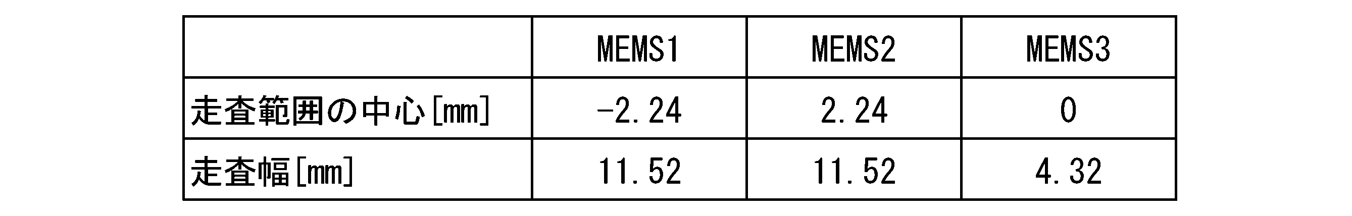
なお、表1では、各走査範囲S1~S3の中心P1~P3について、水平ラインHL上におけるレーザー光照射領域Eの中心Oを0[mm]とし、このレーザー光照射領域Eの中心Oに対して左側をマイナス(-)側とし、右側をプラス(+)側として表している。また、走査範囲S1~S3は、水平ラインHL上における走査幅である。また、以下に示す表2~表12についても同様に表すものとする。
In Table 1, for the centers P1 to P3 of each scanning range S1 to S3, the center O of the laser light irradiation region E on the horizontal line HL is set to 0 [mm] with respect to the center O of the laser light irradiation region E. The left side is represented as the minus (-) side, and the right side is represented as the plus (+) side. Further, the scanning ranges S1 to S3 are scanning widths on the horizontal line HL. In addition, Tables 2 to 12 shown below are also represented in the same manner.
実施例1-2では、上記照明装置1Fに対応した透過型の照明装置を用いた。また、下部左側、上部右側及び右側のレーザー光走査機構4A,4B,4Cのうち、下部左側を「MEMS1」、上部右側を「MEMS2」、右側を「MEMS3」とし、これら3つのMEMS1~MEMS3によるレーザー光BL1~BL3の走査範囲S1~S3及びその中心P1~P3を下記表2に示すように調整し、各レーザー光BL1~BL3の走査範囲S1~S3に応じた配光パターンの重ね合わせによって、図21に示すようなハイビーム用配光パターンの光度分布を満足する配光パターンDPを形成した。
In Example 1-2, a transmissive lighting device corresponding to the above lighting device 1F was used. Of the laser light scanning mechanisms 4A, 4B, and 4C on the lower left side, upper right side, and right side, the lower left side is referred to as "MEMS1", the upper right side is referred to as "MEMS2", and the right side is referred to as "MEMS3". The scanning ranges S1 to S3 of the laser beams BL1 to BL3 and their centers P1 to P3 are adjusted as shown in Table 2 below, and the light distribution patterns corresponding to the scanning ranges S1 to S3 of the laser beams BL1 to BL3 are superposed. , A light distribution pattern DP that satisfies the light intensity distribution of the high beam light distribution pattern as shown in FIG. 21 was formed.

一方、比較例1では、透過型の照明装置を構成する3つのMEMS1~MEMS3のうち、波長変換部材3を挟んだ左側に「MEMS1」、右側に「MEMS2」、上側に「MEMS3」を配置し、これら3つのMEMS1~MEMS3によるレーザー光BL1~BL3の走査範囲S1~S3及びその中心P1~P3を下記表3に示すように調整し、各レーザー光BL1~BL3の走査範囲S1~S3に応じた配光パターンの重ね合わせによって、図21に示すようなハイビーム用配光パターンの光度分布を満足する配光パターンDPを形成した。
On the other hand, in Comparative Example 1, of the three MEMS1 to MEMS3 constituting the transmissive lighting device, "MEMS1" is arranged on the left side, "MEMS2" on the right side, and "MEMS3" on the upper side with the wavelength conversion member 3 sandwiched between them. The scanning ranges S1 to S3 of the laser beams BL1 to BL3 and their centers P1 to P3 by these three MEMS1 to MEMS3 are adjusted as shown in Table 3 below, and the scanning ranges S1 to S3 of the laser beams BL1 to BL3 are adjusted. By superimposing the light distribution patterns, a light distribution pattern DP satisfying the luminous intensity distribution of the high beam light distribution pattern as shown in FIG. 21 was formed.

(実施例2-1,2-2及び比較例2)
実施例2-1では、上記照明装置1Eに対応した反射型の照明装置を用いた。また、下部左側、下部右側及び上部中央側のレーザー光走査機構4A,4B,4Cのうち、下部左側を「MEMS1」、下部右側を「MEMS2」、上部中央側を「MEMS3」とし、これら3つのMEMS1~MEMS3によるレーザー光BL1~BL3の走査範囲S1~S3及びその中心P1~P3を下記表4に示すように調整し、各レーザー光BL1~BL3の走査範囲S1~S3に応じた配光パターンの重ね合わせによって、図21に示すようなハイビーム用配光パターンの光度分布を満足する配光パターンDPを形成した。 (Examples 2-1 and 2-2 and Comparative Example 2)
In Example 2-1 a reflective lighting device corresponding to thelighting device 1E was used. Of the laser light scanning mechanisms 4A, 4B, and 4C on the lower left side, lower right side, and upper center side, the lower left side is referred to as "MEMS1", the lower right side is referred to as "MEMS2", and the upper center side is referred to as "MEMS3". The scanning ranges S1 to S3 of the laser beams BL1 to BL3 by MEMS1 to MEMS3 and their centers P1 to P3 are adjusted as shown in Table 4 below, and the light distribution pattern corresponding to the scanning ranges S1 to S3 of the laser beams BL1 to BL3. By superimposing the above, a light distribution pattern DP satisfying the light intensity distribution of the high beam light distribution pattern as shown in FIG. 21 was formed.
実施例2-1では、上記照明装置1Eに対応した反射型の照明装置を用いた。また、下部左側、下部右側及び上部中央側のレーザー光走査機構4A,4B,4Cのうち、下部左側を「MEMS1」、下部右側を「MEMS2」、上部中央側を「MEMS3」とし、これら3つのMEMS1~MEMS3によるレーザー光BL1~BL3の走査範囲S1~S3及びその中心P1~P3を下記表4に示すように調整し、各レーザー光BL1~BL3の走査範囲S1~S3に応じた配光パターンの重ね合わせによって、図21に示すようなハイビーム用配光パターンの光度分布を満足する配光パターンDPを形成した。 (Examples 2-1 and 2-2 and Comparative Example 2)
In Example 2-1 a reflective lighting device corresponding to the
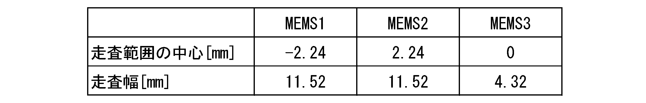
実施例2-2では、上記照明装置1Fに対応した反射型の照明装置を用いた。また、下部左側、上部右側及び右側のレーザー光走査機構4A,4B,4Cのうち、下部左側を「MEMS1」、上部右側を「MEMS2」、右側を「MEMS3」とし、これら3つのMEMS1~MEMS3によるレーザー光BL1~BL3の走査範囲S1~S3及びその中心P1~P3を下記表5に示すように調整し、各レーザー光BL1~BL3の走査範囲S1~S3に応じた配光パターンの重ね合わせによって、図21に示すようなハイビーム用配光パターンの光度分布を満足する配光パターンDPを形成した。
In Example 2-2, a reflection type lighting device corresponding to the above lighting device 1F was used. Of the laser light scanning mechanisms 4A, 4B, and 4C on the lower left side, upper right side, and right side, the lower left side is referred to as "MEMS1", the upper right side is referred to as "MEMS2", and the right side is referred to as "MEMS3". The scanning ranges S1 to S3 of the laser beams BL1 to BL3 and their centers P1 to P3 are adjusted as shown in Table 5 below, and the light distribution patterns corresponding to the scanning ranges S1 to S3 of the laser beams BL1 to BL3 are superposed. , A light distribution pattern DP that satisfies the light intensity distribution of the high beam light distribution pattern as shown in FIG. 21 was formed.

一方、比較例2では、反射型の照明装置を構成する3つのMEMS1~MEMS3のうち、波長変換部材3を挟んだ左側に「MEMS1」、右側に「MEMS2」、上側に「MEMS3」を配置し、これら3つのMEMS1~MEMS3によるレーザー光BL1~BL3の走査範囲S1~S3及びその中心P1~P3を下記表6に示すように調整し、各レーザー光BL1~BL3の走査範囲S1~S3に応じた配光パターンの重ね合わせによって、図21に示すようなハイビーム用配光パターンの光度分布を満足する配光パターンDPを形成した。
On the other hand, in Comparative Example 2, of the three MEMS1 to MEMS3 constituting the reflection type lighting device, "MEMS1" is arranged on the left side, "MEMS2" on the right side, and "MEMS3" on the upper side with the wavelength conversion member 3 sandwiched between them. The scanning ranges S1 to S3 of the laser beams BL1 to BL3 and their centers P1 to P3 by these three MEMS1 to MEMS3 are adjusted as shown in Table 6 below, and the scanning ranges S1 to S3 of the laser beams BL1 to BL3 are adjusted. By superimposing the light distribution patterns, a light distribution pattern DP satisfying the light intensity distribution of the high beam light distribution pattern as shown in FIG. 21 was formed.
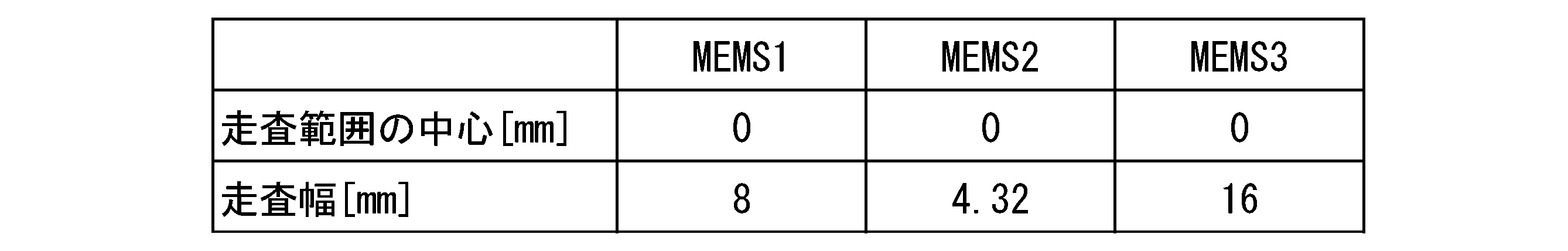
(実施例3-1,3-2及び比較例3)
実施例3-1では、上記照明装置1Gに対応した透過型の照明装置を用いた。また、下部左側、下部右側、上部左側及び下部右側のレーザー光走査機構4A,4B,4C,4Dのうち、下部左側を「MEMS1」、下部右側を「MEMS2」、上部左側を「MEMS3」、上部右側を「MEMS4」とし、これら4つのMEMS1~MEMS4によるレーザー光BL1~BL4の走査範囲S1~S4及びその中心P1~P4を下記表7に示すように調整し、各レーザー光BL1~BL4の走査範囲S1~S4に応じた配光パターンの重ね合わせによって、図21に示すようなハイビーム用配光パターンの光度分布を満足する配光パターンDPを形成した。 (Examples 3-1 and 3-2 and Comparative Example 3)
In Example 3-1 a transmissive lighting device corresponding to thelighting device 1G was used. Of the laser light scanning mechanisms 4A, 4B, 4C, and 4D on the lower left side, lower right side, upper left side, and lower right side, the lower left side is "MEMS1", the lower right side is "MEMS2", the upper left side is "MEMS3", and the upper part. The right side is designated as "MEMS4", and the scanning ranges S1 to S4 of the laser beams BL1 to BL4 and their centers P1 to P4 by these four MEMS1 to MEMS4 are adjusted as shown in Table 7 below, and the scanning of the laser beams BL1 to BL4 is performed. By superimposing the light distribution patterns according to the ranges S1 to S4, a light distribution pattern DP satisfying the light intensity distribution of the high beam light distribution pattern as shown in FIG. 21 was formed.
実施例3-1では、上記照明装置1Gに対応した透過型の照明装置を用いた。また、下部左側、下部右側、上部左側及び下部右側のレーザー光走査機構4A,4B,4C,4Dのうち、下部左側を「MEMS1」、下部右側を「MEMS2」、上部左側を「MEMS3」、上部右側を「MEMS4」とし、これら4つのMEMS1~MEMS4によるレーザー光BL1~BL4の走査範囲S1~S4及びその中心P1~P4を下記表7に示すように調整し、各レーザー光BL1~BL4の走査範囲S1~S4に応じた配光パターンの重ね合わせによって、図21に示すようなハイビーム用配光パターンの光度分布を満足する配光パターンDPを形成した。 (Examples 3-1 and 3-2 and Comparative Example 3)
In Example 3-1 a transmissive lighting device corresponding to the
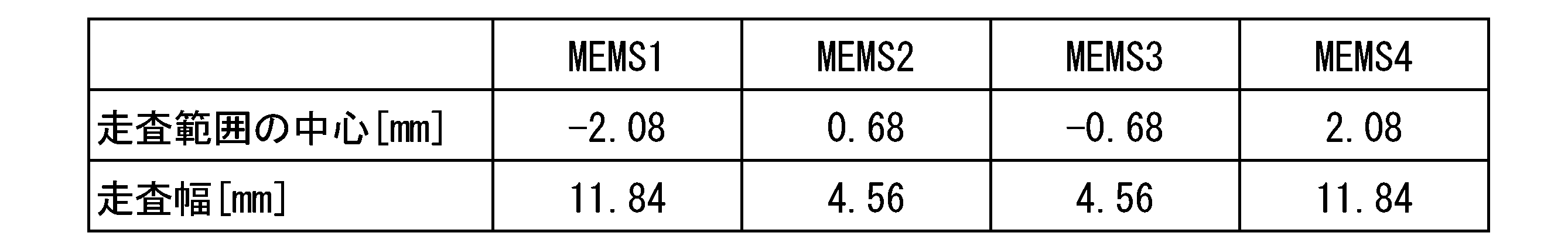
実施例3-2では、上記照明装置1Hに対応した透過型の照明装置を用いた。また、下部左側、上部右側、左側及び右側のレーザー光走査機構4A,4B,4C,4Dのうち、下部左側を「MEMS1」、上部右側を「MEMS2」、左側を「MEMS3」、右側を「MEMS4」とし、これら4つのMEMS1~MEMS4によるレーザー光BL1~BL4の走査範囲S1~S4及びその中心P1~P4を下記表8に示すように調整し、各レーザー光BL1~BL4の走査範囲S1~S4に応じた配光パターンの重ね合わせによって、図21に示すようなハイビーム用配光パターンの光度分布を満足する配光パターンDPを形成した。
In Example 3-2, a transmissive lighting device corresponding to the lighting device 1H was used. Of the laser light scanning mechanisms 4A, 4B, 4C, and 4D on the lower left side, upper right side, left side, and right side, the lower left side is "MEMS1", the upper right side is "MEMS2", the left side is "MEMS3", and the right side is "MEMS4". The scanning ranges S1 to S4 of the laser beams BL1 to BL4 and their centers P1 to P4 by these four MEMS1 to MEMS4 are adjusted as shown in Table 8 below, and the scanning ranges S1 to S4 of the laser beams BL1 to BL4 are adjusted. By superimposing the light distribution patterns according to the above, a light distribution pattern DP satisfying the light intensity distribution of the high beam light distribution pattern as shown in FIG. 21 was formed.

一方、比較例3では、透過型の照明装置を構成する4つのMEMS1~MEMS4のうち、左側に「MEMS1」、右側に「MEMS2」、上側に「MEMS3」、下側に「MEMS4」を配置し、これら4つのMEMS1~MEMS4によるレーザー光BL1~BL4の走査範囲S1~S4及びその中心P1~P4を下記表9に示すように調整し、各レーザー光BL1~BL4の走査範囲S1~S4に応じた配光パターンの重ね合わせによって、図21に示すようなハイビーム用配光パターンの光度分布を満足する配光パターンDPを形成した。
On the other hand, in Comparative Example 3, among the four MEMS1 to MEMS4 constituting the transmissive lighting device, "MEMS1" is arranged on the left side, "MEMS2" is arranged on the right side, "MEMS3" is arranged on the upper side, and "MEMS4" is arranged on the lower side. The scanning ranges S1 to S4 of the laser beams BL1 to BL4 and their centers P1 to P4 by these four MEMS1 to MEMS4 are adjusted as shown in Table 9 below, and correspond to the scanning ranges S1 to S4 of the laser beams BL1 to BL4. By superimposing the light distribution patterns, a light distribution pattern DP satisfying the luminous intensity distribution of the high beam light distribution pattern as shown in FIG. 21 was formed.
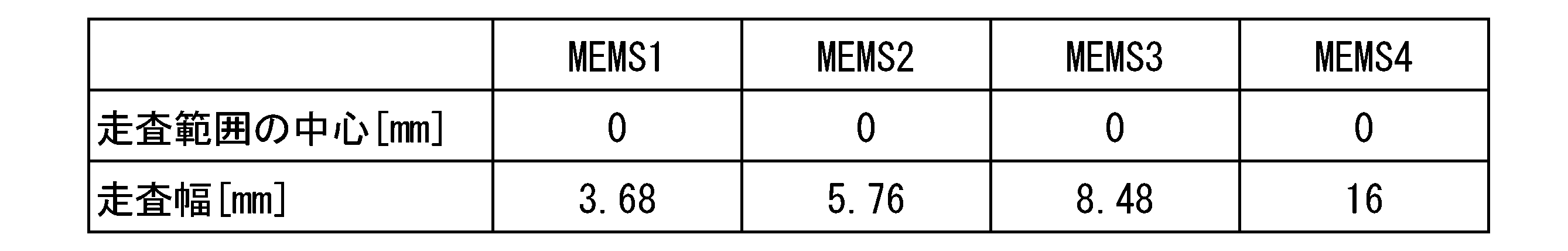
(実施例4-1,4-2及び比較例4)
実施例4-1では、上記照明装置1Gに対応した反射型の照明装置を用いた。また、下部左側、下部右側、上部左側及び下部右側のレーザー光走査機構4A,4B,4C,4Dのうち、下部左側を「MEMS1」、下部右側を「MEMS2」、上部左側を「MEMS3」、上部右側を「MEMS4」とし、これら4つのMEMS1~MEMS4によるレーザー光BL1~BL4の走査範囲S1~S4及びその中心P1~P4を下記表10に示すように調整し、各レーザー光BL1~BL4の走査範囲S1~S4に応じた配光パターンの重ね合わせによって、図21に示すようなハイビーム用配光パターンの光度分布を満足する配光パターンDPを形成した。 (Examples 4-1 and 4-2 and Comparative Example 4)
In Example 4-1 a reflection type lighting device corresponding to thelighting device 1G was used. Of the laser light scanning mechanisms 4A, 4B, 4C, and 4D on the lower left side, lower right side, upper left side, and lower right side, the lower left side is "MEMS1", the lower right side is "MEMS2", the upper left side is "MEMS3", and the upper part. The right side is designated as "MEMS4", and the scanning ranges S1 to S4 of the laser beams BL1 to BL4 and their centers P1 to P4 by these four MEMS1 to MEMS4 are adjusted as shown in Table 10 below, and the scanning of the laser beams BL1 to BL4 is performed. By superimposing the light distribution patterns according to the ranges S1 to S4, a light distribution pattern DP satisfying the light intensity distribution of the high beam light distribution pattern as shown in FIG. 21 was formed.
実施例4-1では、上記照明装置1Gに対応した反射型の照明装置を用いた。また、下部左側、下部右側、上部左側及び下部右側のレーザー光走査機構4A,4B,4C,4Dのうち、下部左側を「MEMS1」、下部右側を「MEMS2」、上部左側を「MEMS3」、上部右側を「MEMS4」とし、これら4つのMEMS1~MEMS4によるレーザー光BL1~BL4の走査範囲S1~S4及びその中心P1~P4を下記表10に示すように調整し、各レーザー光BL1~BL4の走査範囲S1~S4に応じた配光パターンの重ね合わせによって、図21に示すようなハイビーム用配光パターンの光度分布を満足する配光パターンDPを形成した。 (Examples 4-1 and 4-2 and Comparative Example 4)
In Example 4-1 a reflection type lighting device corresponding to the

実施例4-2では、上記照明装置1Hに対応した反射型の照明装置を用いた。また、下部左側、上部右側、左側及び右側のレーザー光走査機構4A,4B,4C,4Dのうち、下部左側を「MEMS1」、上部右側を「MEMS2」、左側を「MEMS3」、右側を「MEMS4」とし、これら4つのMEMS1~MEMS4によるレーザー光BL1~BL4の走査範囲S1~S4及びその中心P1~P4を下記表11に示すように調整し、各レーザー光BL1~BL4の走査範囲S1~S4に応じた配光パターンの重ね合わせによって、図21に示すようなハイビーム用配光パターンの光度分布を満足する配光パターンDPを形成した。
In Example 4-2, a reflective lighting device corresponding to the lighting device 1H was used. Of the laser light scanning mechanisms 4A, 4B, 4C, and 4D on the lower left side, upper right side, left side, and right side, the lower left side is "MEMS1", the upper right side is "MEMS2", the left side is "MEMS3", and the right side is "MEMS4". The scanning ranges S1 to S4 of the laser beams BL1 to BL4 and their centers P1 to P4 by these four MEMS1 to MEMS4 are adjusted as shown in Table 11 below, and the scanning ranges S1 to S4 of the laser beams BL1 to BL4 are adjusted. By superimposing the light distribution patterns according to the above, a light distribution pattern DP satisfying the light intensity distribution of the high beam light distribution pattern as shown in FIG. 21 was formed.

一方、比較例4では、反射型の照明装置を構成する4つのMEMS1~MEMS4のうち、左側に「MEMS1」、右側に「MEMS2」、上側に「MEMS3」、下側に「MEMS4」を配置し、これら4つのMEMS1~MEMS4によるレーザー光BL1~BL4の走査範囲S1~S4及びその中心P1~P4を下記表12に示すように調整し、各レーザー光BL1~BL4の走査範囲S1~S4に応じた配光パターンの重ね合わせによって、図21に示すようなハイビーム用配光パターンの光度分布を満足する配光パターンDPを形成した。
On the other hand, in Comparative Example 4, among the four MEMS1 to MEMS4 constituting the reflection type lighting device, "MEMS1" is arranged on the left side, "MEMS2" is arranged on the right side, "MEMS3" is arranged on the upper side, and "MEMS4" is arranged on the lower side. The scanning ranges S1 to S4 of the laser beams BL1 to BL4 and their centers P1 to P4 by these four MEMS1 to MEMS4 are adjusted as shown in Table 12 below, and correspond to the scanning ranges S1 to S4 of the laser beams BL1 to BL4. By superimposing the light distribution patterns, a light distribution pattern DP satisfying the light intensity distribution of the high beam light distribution pattern as shown in FIG. 21 was formed.

本実施例では、上述した実施例1-1,1-2及び比較例1、実施例2-1,2-2及び比較例2、実施例3-1,3-2及び比較例3、実施例4-1,4-2及び比較例4の各照明装置について、各MEMS1~MEMS3(MEMS4)からレーザー光照射領域Eの中心Oに入射するレーザー光BL1~BL3(BL4)の入射角[°]を計算し、その入射角の最大値(MAX)を求めた。その結果をまとめたものを下記表13に示す。
In this example, Examples 1-1, 1-2 and Comparative Example 1, Examples 2-1, 2-2 and Comparative Example 2, Examples 3-1, 3-2 and Comparative Example 3 described above are carried out. For each of the lighting devices of Examples 4-1 and 4-2 and Comparative Example 4, the incident angles [°] of the laser beams BL1 to BL3 (BL4) incident on the center O of the laser light irradiation region E from the respective MEMS1 to MEMS3 (MEMS4). ] Was calculated, and the maximum value (MAX) of the incident angle was obtained. The results are summarized in Table 13 below.
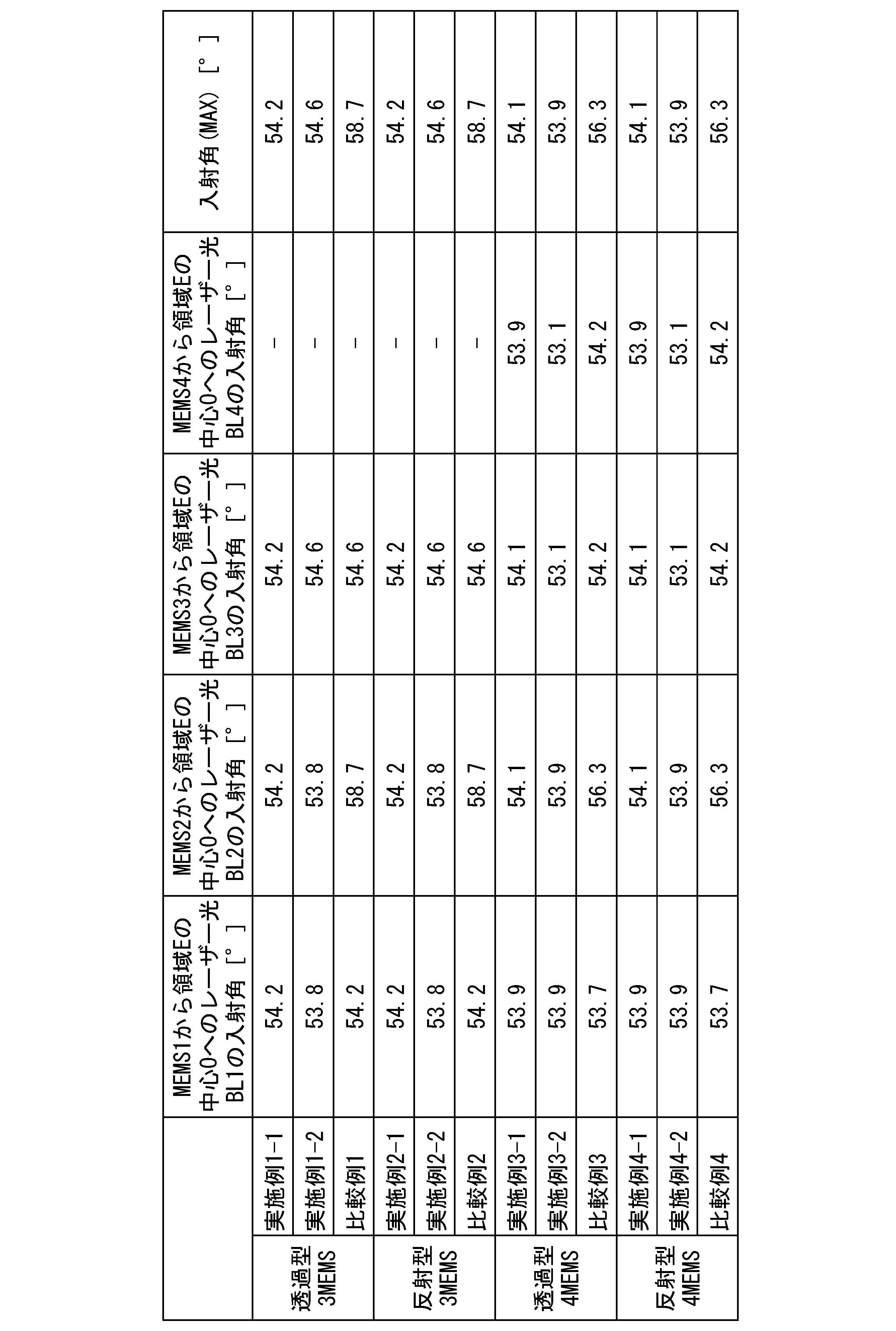
また、本実施例では、上述した実施例1-1,1-2及び比較例1、実施例2-1,2-2及び比較例2、実施例3-1,3-2及び比較例3、実施例4-1,4-2及び比較例4の各照明装置について、各MEMS1~MEMS3(MEMS4)からレーザー光照射領域Eの中心Oに入射するレーザー光BL1~BL3(BL4)のスポットサイズを計算し、入射角が0°となるときのスポットサイズに対する比率(入射比)を求め、更に、その入射比の最大値(MAX)を求めた。その結果をまとめたものを下記表14に示す。
Further, in this example, the above-mentioned Examples 1-1, 1-2 and Comparative Example 1, Examples 2-1, 2-2 and Comparative Example 2, Examples 3-1, 3-2 and Comparative Example 3 , The spot size of the laser beams BL1 to BL3 (BL4) incident on the center O of the laser beam irradiation region E from each MEMS1 to MEMS3 (MEMS4) for each of the lighting devices of Examples 4-1, 4-2 and Comparative Example 4. Was calculated, the ratio (incident ratio) to the spot size when the incident angle became 0 ° was obtained, and the maximum value (MAX) of the incident ratio was further obtained. The results are summarized in Table 14 below.
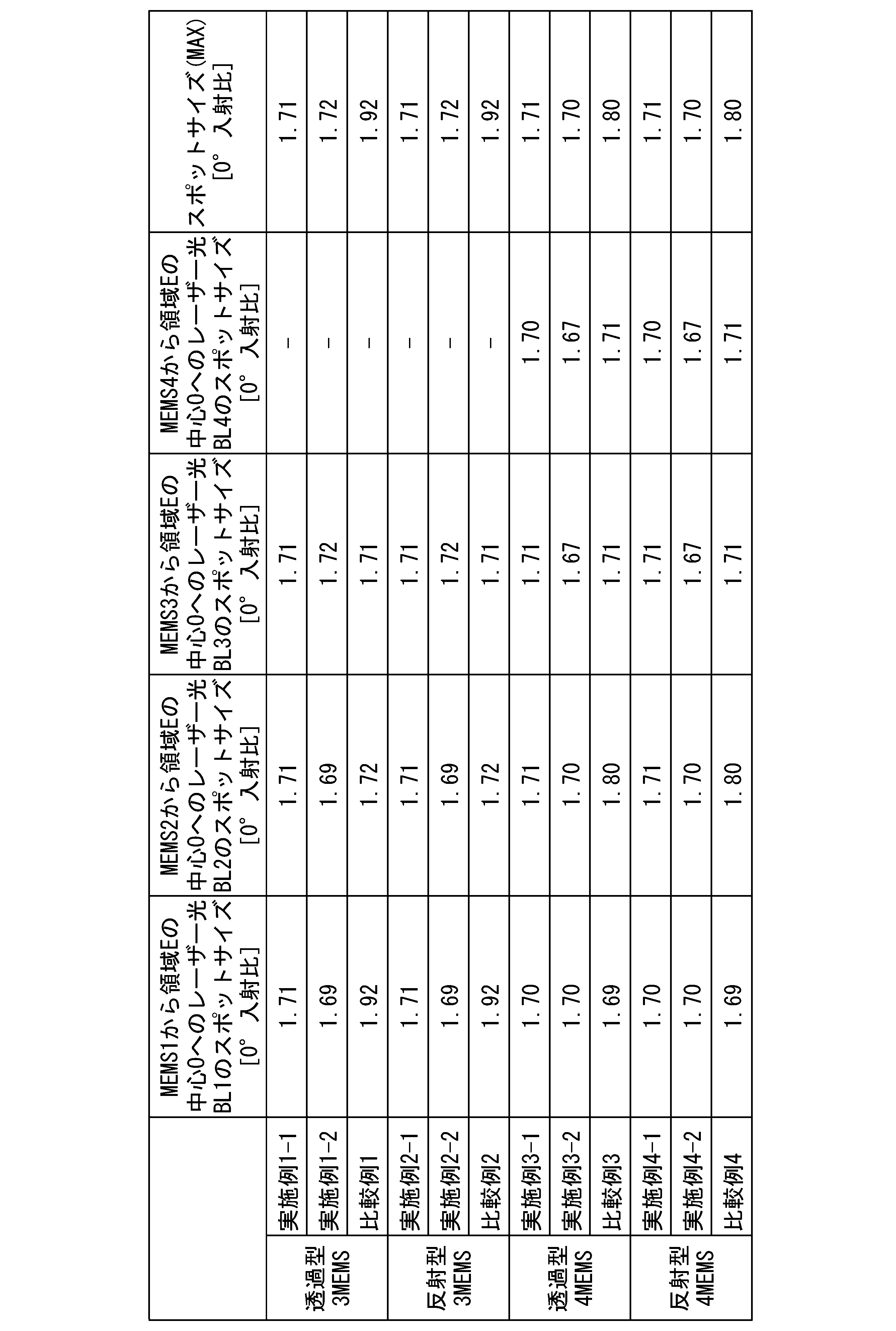
表13及び表14に示すように、実施例1-1,1-2,2-1,2-2,3-1,3-2,4-1,4-2の照明装置は、比較例1,2,3,4の照明装置に比べて、各MEMS1~MEMS3(MEMS4)からレーザー光照射領域Eの中心Oに入射するレーザー光BL1~BL3(BL4)の入射角及びスポットサイズを小さくすることが可能である。
As shown in Tables 13 and 14, the lighting devices of Examples 1-1, 1-2, 2-1, 2, 3-1, 3-2, 4-1, 4-2 are comparative examples. Compared with the lighting devices 1, 2, 3 and 4, the incident angles and spot sizes of the laser beams BL1 to BL3 (BL4) incident on the center O of the laser beam irradiation region E from each MEMS1 to MEMS3 (MEMS4) are reduced. It is possible.
なお、本発明は、上記実施形態のものに必ずしも限定されるものではなく、本発明の趣旨を逸脱しない範囲において種々の変更を加えることが可能である。
具体的に、上記照明装置1A~1Hでは、上述した波長変換部材3A,3Bが破損、欠損又は脱落したときに、投影レンズ200に対してレーザー光BLが直接入射しない角度に設定されているため、このレーザー光走査機構4により走査されるレーザー光BLを吸収又は遮光するための吸光部又は遮光部を灯体の内側に設けることが好ましい。吸光部又は遮光部としては、レーザー光BLを吸収又は遮光する吸光部材又は遮光部材を配置した構成とすればよい。 The present invention is not necessarily limited to that of the above embodiment, and various modifications can be made without departing from the spirit of the present invention.
Specifically, in thelighting devices 1A to 1H, when the wavelength conversion members 3A and 3B described above are damaged, missing or dropped, the angle is set so that the laser light BL does not directly incident on the projection lens 200. It is preferable to provide an absorption part or a light-shielding part inside the lamp body for absorbing or light-shielding the laser light BL scanned by the laser light scanning mechanism 4. The light-absorbing unit or the light-shielding unit may be configured by arranging an light-absorbing member or a light-shielding member that absorbs or shields the laser light BL.
具体的に、上記照明装置1A~1Hでは、上述した波長変換部材3A,3Bが破損、欠損又は脱落したときに、投影レンズ200に対してレーザー光BLが直接入射しない角度に設定されているため、このレーザー光走査機構4により走査されるレーザー光BLを吸収又は遮光するための吸光部又は遮光部を灯体の内側に設けることが好ましい。吸光部又は遮光部としては、レーザー光BLを吸収又は遮光する吸光部材又は遮光部材を配置した構成とすればよい。 The present invention is not necessarily limited to that of the above embodiment, and various modifications can be made without departing from the spirit of the present invention.
Specifically, in the
上記波長変換部材3A,3Bについては、上述した実施形態のものに必ずしも限定されるものではなく、その構成や材質等について適宜選択して用いることが可能である。
The wavelength conversion members 3A and 3B are not necessarily limited to those of the above-described embodiment, and their configurations, materials, and the like can be appropriately selected and used.
例えば、[1]波長変換部材3A,3Bとしては、蛍光体プレートの成形体を基板に接合又は接着したものや、[2]基板の上に蛍光体層(波長変換層)を形成したものなどを用いることができる。
For example, [1] wavelength conversion members 3A and 3B include those in which a molded body of a phosphor plate is bonded or adhered to a substrate, and [2] those in which a phosphor layer (wavelength conversion layer) is formed on a substrate. Can be used.
また、透過型の波長変換部材3Aの場合、透明セラミック基板やガラス基板などの透明基板を用いることができる。一方、反射型の波長変換部材3Bの場合、金属基板の他に、セラミック基板やガラス基板などの表面に反射膜を形成した反射基板を用いることができる。
Further, in the case of the transmission type wavelength conversion member 3A, a transparent substrate such as a transparent ceramic substrate or a glass substrate can be used. On the other hand, in the case of the reflection type wavelength conversion member 3B, in addition to the metal substrate, a reflection substrate having a reflection film formed on the surface of a ceramic substrate, a glass substrate, or the like can be used.
上記[1]の場合、例えば、単結晶蛍光体や蛍光体セラミック、蛍光体分散ガラス、蛍光体分散樹脂シート等などを用いることができる。また、接着剤として、例えば、有機系接着剤や無機系接着剤等の中で透明な接着剤が用いられる。
In the case of the above [1], for example, a single crystal phosphor, a phosphor ceramic, a phosphor-dispersed glass, a phosphor-dispersed resin sheet, or the like can be used. Further, as the adhesive, for example, a transparent adhesive is used among organic adhesives, inorganic adhesives and the like.
一方、上記[2]の場合、例えば、セラミックバインダーやガラスバインダー、樹脂バインダー中に蛍光体粒子を分散させたものを、ディスペンス法や回転塗工法、印刷法、スプレー法等を用いて、基板上に塗工したものを用いることができる。
On the other hand, in the case of the above [2], for example, a ceramic binder, a glass binder, or a resin binder in which phosphor particles are dispersed is placed on a substrate by using a dispensing method, a rotary coating method, a printing method, a spray method, or the like. It is possible to use the one coated in.
蛍光体粒子としては、例えば、酸化物蛍光体や窒化物蛍光体、酸窒化物蛍光体、硫化物蛍光体、フッ化物蛍光体等を粒状化したものを用いることができる。なお、蛍光体層の厚みや蛍光体粒子の粒径(D50)については、特に限定されるものではなく、任意に設定することができる。また、蛍光体層の上に、更に透明保護層を設けてもよい。透明保護層としては、例えば、ガラスやセラミック等の無機物や、シリコーン樹脂、エポキシ樹脂等を用いることができる。
As the phosphor particles, for example, those obtained by granulating an oxide phosphor, a nitride phosphor, an oxynitride phosphor, a sulfide phosphor, a fluoride phosphor, or the like can be used. The thickness of the phosphor layer and the particle size (D50) of the phosphor particles are not particularly limited and can be set arbitrarily. Further, a transparent protective layer may be further provided on the phosphor layer. As the transparent protective layer, for example, an inorganic substance such as glass or ceramic, a silicone resin, an epoxy resin, or the like can be used.
上記レーザー走査機構4については、圧電方式や静電方式、電磁方式のMEMSミラーを用いることができる。また、MEMSミラーについては、波長変換部材3A,3Bの面内でレーザー光BLを走査するため、2軸タイプのもの又は1軸タイプのものを2つ用いることができる。
For the laser scanning mechanism 4, a piezoelectric type, electrostatic type, or electromagnetic type MEMS mirror can be used. Further, as the MEMS mirror, since the laser beam BL is scanned in the plane of the wavelength conversion members 3A and 3B, two 2-axis type mirrors or 2-axis type mirrors can be used.
また、圧電方式の2軸タイプものとしては、1軸共振・1軸非共振タイプ、2軸共振タイプ、2軸非共振タイプなどが挙げられる。さらに、1軸共振・1軸非共振タイプの場合、波長変換部材3A,3Bの面内におけるX軸とY軸とのどちらに非共振軸と共振軸とを割り当ててもよい。
Further, examples of the piezoelectric type 2-axis type include a 1-axis resonance / 1-axis non-resonant type, a 2-axis resonance type, and a 2-axis non-resonance type. Further, in the case of the 1-axis resonance / 1-axis non-resonant type, the non-resonant axis and the resonance axis may be assigned to either the X-axis or the Y-axis in the plane of the wavelength conversion members 3A and 3B.
上記リフレクター5については、上述した平面ミラーに限らず、波長変換部材3A,3Bに向けて反射されるレーザー光BLの歪みを補正する曲面ミラーを用いることも可能である。また、歪み補正用のレンズをリフレクター5と波長変換部材3A,3Bとの間に配置することも可能である。
The reflector 5 is not limited to the plane mirror described above, but a curved mirror that corrects the distortion of the laser beam BL reflected toward the wavelength conversion members 3A and 3B can also be used. It is also possible to arrange the distortion correction lens between the reflector 5 and the wavelength conversion members 3A and 3B.
上記投影レンズ200については、単体のレンズに限らず、複数のレンズを組み合わせたもの(群レンズ)を用いてもよい。また、レンズは、球面タイプに限らず、非球面タイプのものを用いてもよい。
The projection lens 200 is not limited to a single lens, but a combination of a plurality of lenses (group lens) may be used. Further, the lens is not limited to the spherical type, and an aspherical type may be used.
また、本発明を適用した照明装置は、上述した車両用灯具に対して好適に用いられるものの、車両用灯具以外の用途にも幅広く適用することが可能である。
Further, although the lighting device to which the present invention is applied is suitably used for the above-mentioned vehicle lighting equipment, it can be widely applied to applications other than vehicle lighting equipment.
1A~1H…照明装置 2,2A,2B,2C,2D…レーザー光源 3,3A,3B…波長変換部材 4,4A,4B,4C,4D…レーザー光走査機構 5…リフレクター 6…反射板 100…車両用灯具 200…投影レンズ BL…レーザー光 YL…蛍光光 WL…照明光 E…レーザー光照射領域 O…レーザー光照射領域の中心 S,S1,S2,S3,S4…レーザー光の走査範囲 P,P1,P2,P3,P4…レーザー光の走査範囲の中心 Q,Q1,Q2,Q3,Q4…レーザー走査機構の中心 VL,VL1,VL2,VL3,VL4…鉛直ライン HL…水平ライン
1A-1H ... Illumination device 2,2A, 2B, 2C, 2D ... Laser light source 3,3A, 3B ... Wavelength conversion member 4,4A, 4B, 4C, 4D ... Laser light scanning mechanism 5 ... Reflector 6 ... Reflector 100 ... Vehicle lighting equipment 200 ... Projection lens BL ... Laser light YL ... Fluorescent light WL ... Illumination light E ... Laser light irradiation area O ... Center of laser light irradiation area S, S1, S2, S3, S4 ... Laser light scanning range P, P1, P2, P3, P4 ... Center of laser light scanning range Q, Q1, Q2, Q3, Q4 ... Center of laser scanning mechanism VL, VL1, VL2, VL3, VL4 ... Vertical line HL ... Horizontal line
Claims (10)
- レーザー光を出射するレーザー光源と、
前記レーザー光が照射されるレーザー光照射領域を含み、前記レーザー光の照射により励起されて波長変換された光を発する波長変換部材と、
前記レーザー光照射領域に照射されるレーザー光を走査することによって、前記レーザー光の走査範囲に応じた配光パターンを形成するレーザー光走査機構と、
前記配光パターンを形成する照明光を前方に向けて投影する投影レンズとを備え、
前記レーザー光走査機構により走査されるレーザー光の前記波長変換部材に対する入射角が、前記波長変換部材が破損、欠損又は脱落したときに、前記投影レンズに対してレーザー光が直接入射しない角度に設定されており、
前記レーザー光源及び前記レーザー走査機構は、前記波長変換部材を挟んだ前記配光パターンの上側と下側との少なくとも一方に対応した位置にあり、なお且つ、前記配光パターンの左側に対応した一方側と、前記配光パターンの右側に対応した他方側との何れかにずらして配置されている、
照明装置。 A laser light source that emits laser light and
A wavelength conversion member that includes a laser beam irradiation region to which the laser beam is irradiated and emits wavelength-converted light that is excited by the irradiation of the laser beam.
A laser light scanning mechanism that forms a light distribution pattern according to the scanning range of the laser light by scanning the laser light emitted to the laser light irradiation region.
It is provided with a projection lens that projects the illumination light forming the light distribution pattern toward the front.
The angle of incidence of the laser light scanned by the laser light scanning mechanism on the wavelength conversion member is set to an angle at which the laser light does not directly incident on the projection lens when the wavelength conversion member is damaged, missing or dropped. Has been
The laser light source and the laser scanning mechanism are located at positions corresponding to at least one of the upper side and the lower side of the light distribution pattern sandwiching the wavelength conversion member, and correspond to the left side of the light distribution pattern. It is arranged so as to be offset from the side and the other side corresponding to the right side of the light distribution pattern.
Lighting device. - 前記波長変換部材を平面視したときに、前記レーザー光の走査範囲の中心が、前記レーザー光走査機構の中心を通る前記配光パターンの上下方向に対応した鉛直ラインと、前記レーザー光照射領域の中心を通る前記配光パターンの左右方向に対応した水平ラインとの交点に位置する、
請求項1に記載の照明装置。 When the wavelength conversion member is viewed in a horizontal view, the center of the scanning range of the laser light is a vertical line corresponding to the vertical direction of the light distribution pattern passing through the center of the laser light scanning mechanism, and the laser light irradiation region. It is located at the intersection with the horizontal line corresponding to the left-right direction of the light distribution pattern passing through the center.
The lighting device according to claim 1. - 前記レーザー光源及び前記レーザー走査機構は、前記配光パターンの左側に対応した一方側と、前記配光パターンの右側に対応した他方側とに各々ずらして配置され、
前記一方側のレーザー光走査機構は、前記一方側のレーザー光源から前記レーザー光照射領域に向けて照射される一方のレーザー光を走査することによって、前記一方のレーザー光の走査範囲に応じた配光パターンを形成し、
前記他方側のレーザー光走査機構は、前記他方側のレーザー光源から前記レーザー光照射領域に向けて照射される他方のレーザー光を走査することによって、前記他方のレーザー光の走査範囲に応じた配光パターンを形成し、
前記一方のレーザー光の走査範囲に応じた配光パターンと、前記他方のレーザー光の走査範囲に応じた配光パターンとの重ね合わせによって、1つの合成配光パターンを形成している、
請求項1又は2に記載の照明装置。 The laser light source and the laser scanning mechanism are arranged so as to be offset from one side corresponding to the left side of the light distribution pattern and the other side corresponding to the right side of the light distribution pattern.
The laser light scanning mechanism on one side scans one laser light emitted from the laser light source on the one side toward the laser light irradiation region, thereby arranging the laser light according to the scanning range of the one laser light. Form a light pattern,
The laser light scanning mechanism on the other side scans the other laser light emitted from the laser light source on the other side toward the laser light irradiation region, thereby arranging the laser light according to the scanning range of the other laser light. Form a light pattern,
One synthetic light distribution pattern is formed by superimposing the light distribution pattern according to the scanning range of the one laser light and the light distribution pattern according to the scanning range of the other laser light.
The lighting device according to claim 1 or 2. - 前記波長変換部材を平面視したときに、前記一方のレーザー光の走査範囲の中心及び前記他方のレーザー光の走査範囲の中心が、各々の前記レーザー光走査機構の中心を通る前記配光パターンの上下方向に対応した鉛直ラインと、前記レーザー光照射領域の中心を通る前記配光パターンの左右方向に対応した水平ラインとの交点に各々位置する、
請求項3に記載の照明装置。 When the wavelength conversion member is viewed in a plan view, the center of the scanning range of the one laser beam and the center of the scanning range of the other laser beam pass through the center of each of the laser light scanning mechanisms. It is located at the intersection of the vertical line corresponding to the vertical direction and the horizontal line corresponding to the horizontal direction of the light distribution pattern passing through the center of the laser beam irradiation region.
The lighting device according to claim 3. - 前記レーザー光源及び前記レーザー走査機構は、前記波長変換部材を挟んだ前記配光パターンの上側又は下側、若しくは上側及び下側に対応した位置にあり、なお且つ、前記一方側と前記他方側との間に追加して配置され、
前記追加側のレーザー光走査機構は、前記追加側のレーザー光源から前記レーザー光照射領域に向けて照射される追加のレーザー光を走査することによって、前記追加のレーザー光の走査範囲に応じた配光パターンを形成し、
前記一方のレーザー光の走査範囲に応じた配光パターンと、前記他方のレーザー光の走査範囲に応じた配光パターンと、前記追加のレーザー光の走査範囲に応じた配光パターンとの重ね合わせによって、1つの合成配光パターンを形成している、
請求項1~4の何れか一項に記載の照明装置。 The laser light source and the laser scanning mechanism are located at positions corresponding to the upper side or the lower side, or the upper side and the lower side of the light distribution pattern sandwiching the wavelength conversion member, and the one side and the other side. Additional placement between
The laser light scanning mechanism on the additional side scans the additional laser light emitted from the laser light source on the additional side toward the laser light irradiation region, thereby arranging the laser light according to the scanning range of the additional laser light. Form a light pattern,
A superposition of a light distribution pattern according to the scanning range of one laser beam, a light distribution pattern corresponding to the scanning range of the other laser light, and a light distribution pattern corresponding to the scanning range of the additional laser light. To form one synthetic light distribution pattern,
The lighting device according to any one of claims 1 to 4. - 前記波長変換部材を平面視したときに、前記追加のレーザー光の走査範囲の中心が、前記追加側のレーザー光走査機構の中心を通る前記配光パターンの上下方向に対応した鉛直ラインと、前記レーザー光照射領域の中心を通る前記配光パターンの左右方向に対応した水平ラインとの交点に位置する、
請求項5に記載の照明装置。 When the wavelength conversion member is viewed in a horizontal view, the center of the scanning range of the additional laser light is a vertical line corresponding to the vertical direction of the light distribution pattern passing through the center of the laser light scanning mechanism on the additional side, and the above. It is located at the intersection with the horizontal line corresponding to the left-right direction of the light distribution pattern passing through the center of the laser light irradiation region.
The lighting device according to claim 5. - 前記レーザー光源及び前記レーザー走査機構は、前記波長変換部材を挟んだ前記配光パターンの左側又は右側、若しくは左側及び右側に対応した位置に追加して配置され、
前記追加側のレーザー光走査機構は、前記追加側のレーザー光源から前記レーザー光照射領域に向けて照射される追加のレーザー光を走査することによって、前記追加のレーザー光の走査範囲に応じた配光パターンを形成し、
前記一方のレーザー光の走査範囲に応じた配光パターンと、前記他方のレーザー光の走査範囲に応じた配光パターンと、前記追加のレーザー光の走査範囲に応じた配光パターンとの重ね合わせによって、1つの合成配光パターンを形成している、
請求項1~4の何れか一項に記載の照明装置。 The laser light source and the laser scanning mechanism are additionally arranged at positions corresponding to the left side or the right side, or the left side and the right side of the light distribution pattern sandwiching the wavelength conversion member.
The laser light scanning mechanism on the additional side scans the additional laser light emitted from the laser light source on the additional side toward the laser light irradiation region, thereby arranging the laser light according to the scanning range of the additional laser light. Form a light pattern,
A superposition of a light distribution pattern according to the scanning range of one laser beam, a light distribution pattern corresponding to the scanning range of the other laser light, and a light distribution pattern corresponding to the scanning range of the additional laser light. To form one synthetic light distribution pattern,
The lighting device according to any one of claims 1 to 4. - 前記波長変換部材を平面視したときに、前記追加のレーザー光の走査範囲の中心が、前記レーザー光照射領域の中心に対して前記追加側のレーザー光走査機構が配置された側とは反対側に位置する、
請求項7に記載の照明装置。 When the wavelength conversion member is viewed in a plan view, the center of the scanning range of the additional laser light is opposite to the center of the laser light irradiation region on the side opposite to the side where the laser light scanning mechanism on the additional side is arranged. Located in,
The lighting device according to claim 7. - 前記レーザー光照射領域は、前記波長変換部材を平面視したときに、前記配光パターンの左右方向に対応した幅が、前記配光パターンの上下方向に対応した高さよりも長い、
請求項1~8の何れか一項に記載の照明装置。 When the wavelength conversion member is viewed in a plan view, the width of the laser light irradiation region corresponding to the left-right direction of the light distribution pattern is longer than the height corresponding to the vertical direction of the light distribution pattern.
The lighting device according to any one of claims 1 to 8. - 請求項1~9の何れか一項に記載の照明装置を備える車両用灯具。 A vehicle lamp provided with the lighting device according to any one of claims 1 to 9.
Priority Applications (3)
| Application Number | Priority Date | Filing Date | Title |
|---|---|---|---|
| EP21747920.3A EP4098937A4 (en) | 2020-01-30 | 2021-01-19 | Illumination device and vehicle lamp |
| US17/794,765 US11698176B2 (en) | 2020-01-30 | 2021-01-19 | Illumination device and vehicle lamp |
| CN202180011067.3A CN115023569A (en) | 2020-01-30 | 2021-01-19 | Lighting device and vehicle lamp |
Applications Claiming Priority (2)
| Application Number | Priority Date | Filing Date | Title |
|---|---|---|---|
| JP2020-013645 | 2020-01-30 | ||
| JP2020013645A JP7382241B2 (en) | 2020-01-30 | 2020-01-30 | Lighting equipment and vehicle lights |
Publications (1)
| Publication Number | Publication Date |
|---|---|
| WO2021153342A1 true WO2021153342A1 (en) | 2021-08-05 |
Family
ID=77078872
Family Applications (1)
| Application Number | Title | Priority Date | Filing Date |
|---|---|---|---|
| PCT/JP2021/001647 WO2021153342A1 (en) | 2020-01-30 | 2021-01-19 | Illumination device and vehicle lamp |
Country Status (5)
| Country | Link |
|---|---|
| US (1) | US11698176B2 (en) |
| EP (1) | EP4098937A4 (en) |
| JP (1) | JP7382241B2 (en) |
| CN (1) | CN115023569A (en) |
| WO (1) | WO2021153342A1 (en) |
Cited By (1)
| Publication number | Priority date | Publication date | Assignee | Title |
|---|---|---|---|---|
| US11698176B2 (en) | 2020-01-30 | 2023-07-11 | Stanley Electric Co., Ltd. | Illumination device and vehicle lamp |
Citations (9)
| Publication number | Priority date | Publication date | Assignee | Title |
|---|---|---|---|---|
| JP2016507135A (en) * | 2013-02-07 | 2016-03-07 | チザラ リヒトシステーメ ゲーエムベーハーZizala Lichtsysteme GmbH | Automotive headlight and light distribution generation method |
| JP2016134357A (en) * | 2015-01-22 | 2016-07-25 | スタンレー電気株式会社 | Vehicular lighting fixture |
| JP2016528671A (en) * | 2013-07-04 | 2016-09-15 | チザラ リヒトシステーメ ゲーエムベーハーZizala Lichtsysteme GmbH | Vehicle headlamp |
| JP2017191760A (en) * | 2016-04-15 | 2017-10-19 | シャープ株式会社 | Luminaire and vehicular headlight |
| JP6312484B2 (en) | 2014-03-25 | 2018-04-18 | スタンレー電気株式会社 | head lamp |
| JP2018106825A (en) * | 2016-12-22 | 2018-07-05 | 株式会社小糸製作所 | Vehicular lighting fixture |
| JP2019220605A (en) * | 2018-06-21 | 2019-12-26 | スタンレー電気株式会社 | Light source device and method for driving light source device |
| JP2020004517A (en) * | 2018-06-26 | 2020-01-09 | パナソニックIpマネジメント株式会社 | Lighting device and light emitting device |
| JP2020013645A (en) | 2018-07-13 | 2020-01-23 | オムロン株式会社 | Optical sensor |
Family Cites Families (12)
| Publication number | Priority date | Publication date | Assignee | Title |
|---|---|---|---|---|
| JP5122542B2 (en) * | 2009-09-15 | 2013-01-16 | シャープ株式会社 | Light emitting device, lighting device, and light detector |
| US10507759B2 (en) * | 2012-07-27 | 2019-12-17 | Valeo Vision | Adaptive lighting system for an automobile vehicle |
| KR101693922B1 (en) * | 2014-07-10 | 2017-01-09 | 현대자동차주식회사 | Laser optical system for head lamp |
| CN111347967B (en) * | 2014-11-07 | 2023-06-16 | 大日本印刷株式会社 | Lighting device and vehicle |
| DE102014016853A1 (en) * | 2014-11-13 | 2016-05-19 | Audi Ag | Single headlight for a motor vehicle |
| FR3030017B1 (en) * | 2014-12-10 | 2019-10-04 | Valeo Vision | LUMINOUS MODULE AND PROJECTOR PROVIDED WITH SUCH A MODULE. |
| JP6613547B2 (en) * | 2015-04-23 | 2019-12-04 | スタンレー電気株式会社 | Vehicle lighting |
| AT517519B1 (en) * | 2015-08-03 | 2017-04-15 | Zkw Group Gmbh | A method for driving a laser lighting device for a vehicle headlight |
| KR101811595B1 (en) * | 2015-09-04 | 2017-12-22 | 엘지전자 주식회사 | Headlamp for vehicle and Vehicle including the same |
| JP2017097968A (en) * | 2015-11-18 | 2017-06-01 | スタンレー電気株式会社 | Vehicular lighting fixture |
| AT517957B1 (en) * | 2015-12-22 | 2017-06-15 | Zkw Group Gmbh | Method for controlling a motor vehicle headlight |
| JP7382241B2 (en) | 2020-01-30 | 2023-11-16 | スタンレー電気株式会社 | Lighting equipment and vehicle lights |
-
2020
- 2020-01-30 JP JP2020013645A patent/JP7382241B2/en active Active
-
2021
- 2021-01-19 WO PCT/JP2021/001647 patent/WO2021153342A1/en unknown
- 2021-01-19 EP EP21747920.3A patent/EP4098937A4/en active Pending
- 2021-01-19 US US17/794,765 patent/US11698176B2/en active Active
- 2021-01-19 CN CN202180011067.3A patent/CN115023569A/en active Pending
Patent Citations (9)
| Publication number | Priority date | Publication date | Assignee | Title |
|---|---|---|---|---|
| JP2016507135A (en) * | 2013-02-07 | 2016-03-07 | チザラ リヒトシステーメ ゲーエムベーハーZizala Lichtsysteme GmbH | Automotive headlight and light distribution generation method |
| JP2016528671A (en) * | 2013-07-04 | 2016-09-15 | チザラ リヒトシステーメ ゲーエムベーハーZizala Lichtsysteme GmbH | Vehicle headlamp |
| JP6312484B2 (en) | 2014-03-25 | 2018-04-18 | スタンレー電気株式会社 | head lamp |
| JP2016134357A (en) * | 2015-01-22 | 2016-07-25 | スタンレー電気株式会社 | Vehicular lighting fixture |
| JP2017191760A (en) * | 2016-04-15 | 2017-10-19 | シャープ株式会社 | Luminaire and vehicular headlight |
| JP2018106825A (en) * | 2016-12-22 | 2018-07-05 | 株式会社小糸製作所 | Vehicular lighting fixture |
| JP2019220605A (en) * | 2018-06-21 | 2019-12-26 | スタンレー電気株式会社 | Light source device and method for driving light source device |
| JP2020004517A (en) * | 2018-06-26 | 2020-01-09 | パナソニックIpマネジメント株式会社 | Lighting device and light emitting device |
| JP2020013645A (en) | 2018-07-13 | 2020-01-23 | オムロン株式会社 | Optical sensor |
Non-Patent Citations (1)
| Title |
|---|
| See also references of EP4098937A4 |
Cited By (1)
| Publication number | Priority date | Publication date | Assignee | Title |
|---|---|---|---|---|
| US11698176B2 (en) | 2020-01-30 | 2023-07-11 | Stanley Electric Co., Ltd. | Illumination device and vehicle lamp |
Also Published As
| Publication number | Publication date |
|---|---|
| EP4098937A1 (en) | 2022-12-07 |
| JP7382241B2 (en) | 2023-11-16 |
| JP2021120922A (en) | 2021-08-19 |
| US11698176B2 (en) | 2023-07-11 |
| CN115023569A (en) | 2022-09-06 |
| US20230075945A1 (en) | 2023-03-09 |
| EP4098937A4 (en) | 2024-01-31 |
Similar Documents
| Publication | Publication Date | Title |
|---|---|---|
| JP5157883B2 (en) | Vehicle headlamp | |
| JP6606862B2 (en) | Vehicle lighting | |
| US20150176778A1 (en) | Lighting device | |
| JP5907384B2 (en) | Vehicle headlamp | |
| KR102155080B1 (en) | Vehicle headlamp | |
| WO2014002630A1 (en) | Vehicle lamp and control method therefor | |
| US20150219302A1 (en) | Vehicle lamp | |
| EP3205929B1 (en) | Optical scanning device | |
| WO2019234795A1 (en) | Light impingement device | |
| US20160161074A1 (en) | Lamp unit | |
| JP6033586B2 (en) | Lighting device and vehicle headlamp | |
| KR20180113612A (en) | Head-up display device | |
| WO2020241254A1 (en) | Vehicle lamp fitting | |
| WO2021153342A1 (en) | Illumination device and vehicle lamp | |
| WO2021153338A1 (en) | Lighting device and vehicle lamp fixture | |
| JP6454951B2 (en) | Vehicle headlamp | |
| JP7023672B2 (en) | Vehicle lighting fixtures, control devices and control methods | |
| JP7081917B2 (en) | Vehicle lighting | |
| EP3537032B1 (en) | Lighting tool for vehicle | |
| WO2016009816A1 (en) | Vehicle-mounted light source device | |
| JP2020059377A (en) | Light irradiation system | |
| JP7125473B2 (en) | lighting unit | |
| JP7151152B2 (en) | vehicle lamp | |
| JP2021118052A (en) | Luminaire and vehicular lighting fixture | |
| JP7244008B2 (en) | vehicle lamp |
Legal Events
| Date | Code | Title | Description |
|---|---|---|---|
| 121 | Ep: the epo has been informed by wipo that ep was designated in this application |
Ref document number: 21747920 Country of ref document: EP Kind code of ref document: A1 |
|
| NENP | Non-entry into the national phase |
Ref country code: DE |
|
| ENP | Entry into the national phase |
Ref document number: 2021747920 Country of ref document: EP Effective date: 20220830 |