WO2021149447A1 - 操船支援装置 - Google Patents
操船支援装置 Download PDFInfo
- Publication number
- WO2021149447A1 WO2021149447A1 PCT/JP2020/048156 JP2020048156W WO2021149447A1 WO 2021149447 A1 WO2021149447 A1 WO 2021149447A1 JP 2020048156 W JP2020048156 W JP 2020048156W WO 2021149447 A1 WO2021149447 A1 WO 2021149447A1
- Authority
- WO
- WIPO (PCT)
- Prior art keywords
- ship
- zone
- collision
- support device
- predicted
- Prior art date
- Legal status (The legal status is an assumption and is not a legal conclusion. Google has not performed a legal analysis and makes no representation as to the accuracy of the status listed.)
- Ceased
Links
Images




Classifications
-
- G—PHYSICS
- G05—CONTROLLING; REGULATING
- G05D—SYSTEMS FOR CONTROLLING OR REGULATING NON-ELECTRIC VARIABLES
- G05D1/00—Control of position, course, altitude or attitude of land, water, air or space vehicles, e.g. using automatic pilots
- G05D1/02—Control of position or course in two dimensions
- G05D1/0206—Control of position or course in two dimensions specially adapted to water vehicles
-
- B—PERFORMING OPERATIONS; TRANSPORTING
- B63—SHIPS OR OTHER WATERBORNE VESSELS; RELATED EQUIPMENT
- B63B—SHIPS OR OTHER WATERBORNE VESSELS; EQUIPMENT FOR SHIPPING
- B63B43/00—Improving safety of vessels, e.g. damage control, not otherwise provided for
- B63B43/18—Improving safety of vessels, e.g. damage control, not otherwise provided for preventing collision or grounding; reducing collision damage
-
- B—PERFORMING OPERATIONS; TRANSPORTING
- B63—SHIPS OR OTHER WATERBORNE VESSELS; RELATED EQUIPMENT
- B63B—SHIPS OR OTHER WATERBORNE VESSELS; EQUIPMENT FOR SHIPPING
- B63B49/00—Arrangements of nautical instruments or navigational aids
-
- B—PERFORMING OPERATIONS; TRANSPORTING
- B63—SHIPS OR OTHER WATERBORNE VESSELS; RELATED EQUIPMENT
- B63B—SHIPS OR OTHER WATERBORNE VESSELS; EQUIPMENT FOR SHIPPING
- B63B79/00—Monitoring properties or operating parameters of vessels in operation
- B63B79/30—Monitoring properties or operating parameters of vessels in operation for diagnosing, testing or predicting the integrity or performance of vessels
-
- B—PERFORMING OPERATIONS; TRANSPORTING
- B63—SHIPS OR OTHER WATERBORNE VESSELS; RELATED EQUIPMENT
- B63B—SHIPS OR OTHER WATERBORNE VESSELS; EQUIPMENT FOR SHIPPING
- B63B79/00—Monitoring properties or operating parameters of vessels in operation
- B63B79/40—Monitoring properties or operating parameters of vessels in operation for controlling the operation of vessels, e.g. monitoring their speed, routing or maintenance schedules
-
- G—PHYSICS
- G01—MEASURING; TESTING
- G01C—MEASURING DISTANCES, LEVELS OR BEARINGS; SURVEYING; NAVIGATION; GYROSCOPIC INSTRUMENTS; PHOTOGRAMMETRY OR VIDEOGRAMMETRY
- G01C21/00—Navigation; Navigational instruments not provided for in groups G01C1/00 - G01C19/00
- G01C21/20—Instruments for performing navigational calculations
-
- G—PHYSICS
- G01—MEASURING; TESTING
- G01C—MEASURING DISTANCES, LEVELS OR BEARINGS; SURVEYING; NAVIGATION; GYROSCOPIC INSTRUMENTS; PHOTOGRAMMETRY OR VIDEOGRAMMETRY
- G01C21/00—Navigation; Navigational instruments not provided for in groups G01C1/00 - G01C19/00
- G01C21/20—Instruments for performing navigational calculations
- G01C21/203—Instruments for performing navigational calculations specially adapted for water-borne vessels
-
- G—PHYSICS
- G01—MEASURING; TESTING
- G01S—RADIO DIRECTION-FINDING; RADIO NAVIGATION; DETERMINING DISTANCE OR VELOCITY BY USE OF RADIO WAVES; LOCATING OR PRESENCE-DETECTING BY USE OF THE REFLECTION OR RERADIATION OF RADIO WAVES; ANALOGOUS ARRANGEMENTS USING OTHER WAVES
- G01S13/00—Systems using the reflection or reradiation of radio waves, e.g. radar systems; Analogous systems using reflection or reradiation of waves whose nature or wavelength is irrelevant or unspecified
- G01S13/88—Radar or analogous systems specially adapted for specific applications
- G01S13/93—Radar or analogous systems specially adapted for specific applications for anti-collision purposes
- G01S13/937—Radar or analogous systems specially adapted for specific applications for anti-collision purposes of marine craft
-
- G—PHYSICS
- G01—MEASURING; TESTING
- G01S—RADIO DIRECTION-FINDING; RADIO NAVIGATION; DETERMINING DISTANCE OR VELOCITY BY USE OF RADIO WAVES; LOCATING OR PRESENCE-DETECTING BY USE OF THE REFLECTION OR RERADIATION OF RADIO WAVES; ANALOGOUS ARRANGEMENTS USING OTHER WAVES
- G01S7/00—Details of systems according to groups G01S13/00, G01S15/00, G01S17/00
- G01S7/02—Details of systems according to groups G01S13/00, G01S15/00, G01S17/00 of systems according to group G01S13/00
- G01S7/04—Display arrangements
- G01S7/06—Cathode-ray tube displays or other two dimensional or three-dimensional displays
- G01S7/10—Providing two-dimensional [2D] co-ordinated display of distance and direction
- G01S7/12—Plan-position indicators, i.e. P.P.I.
-
- G—PHYSICS
- G08—SIGNALLING
- G08G—TRAFFIC CONTROL SYSTEMS
- G08G3/00—Traffic control systems for marine craft
- G08G3/02—Anti-collision systems
-
- G—PHYSICS
- G01—MEASURING; TESTING
- G01S—RADIO DIRECTION-FINDING; RADIO NAVIGATION; DETERMINING DISTANCE OR VELOCITY BY USE OF RADIO WAVES; LOCATING OR PRESENCE-DETECTING BY USE OF THE REFLECTION OR RERADIATION OF RADIO WAVES; ANALOGOUS ARRANGEMENTS USING OTHER WAVES
- G01S13/00—Systems using the reflection or reradiation of radio waves, e.g. radar systems; Analogous systems using reflection or reradiation of waves whose nature or wavelength is irrelevant or unspecified
- G01S13/66—Radar-tracking systems; Analogous systems
Definitions
- the present invention relates to a ship maneuvering support device.
- Non-Patent Document 1 discloses a calculation method of the zone by this kind of ship maneuvering support device.
- Non-Patent Document 1 discloses a method of calculating OZT (Obstacle Z Freshne by Target), which is a space hindered by the existence and movement of the other ship in the own ship's action space.
- the calculation method of OZT according to Non-Patent Document 1 is as follows. That is, by defining the arrival time probability distribution that probabilistically indicates the time when the own and other ships arrive at an arbitrary point in consideration of the speed error that occurs in the own and other ships, the own and other ships at any point Find the probability of simultaneous existence. A place where the probability of simultaneous existence is higher than a predetermined probability value is defined as an OZT having a possibility of collision.
- the OZT is calculated by regarding the own ship and the other ship as points, and the actual size of the own ship and the other ship is not taken into consideration.
- the operator steers the ship so as to avoid OZT on the display, abnormal approach or collision between the ships occurs because the own ship and other ships actually have the physical size. There is a fear.
- Non-Patent Document 1 the method of obtaining OZT by obtaining the simultaneous existence probability of own and other ships as in Non-Patent Document 1 requires an extremely large amount of calculation. Therefore, in the method of Non-Patent Document 1, it is difficult to increase the OZT calculation points from the viewpoint of the calculation load, and it is difficult to improve the spatial resolution of the OZT display.
- the present invention has been made in view of the above circumstances, and an object of the present invention is to be able to generate display data that accurately indicates the risk of collision, and to reduce the calculation load of display data generation.
- the purpose is to provide a ship maneuvering support device.
- this ship maneuvering support device includes another ship data acquisition unit, another ship future position prediction unit, own ship data acquisition unit, own ship future position prediction unit, risk calculation unit, and display data generation unit.
- the other ship data acquisition unit acquires information on the position and speed of the other ship.
- the future position prediction unit of the other ship will be used when the other ship continues to sail on the same course and at the same speed based on the position and speed of the other ship acquired by the data acquisition unit of the other ship. Predict the position of other vessels at multiple times.
- the own ship data acquisition unit acquires information on the position and speed of the own ship.
- the own ship future position prediction unit continues to sail on the course arbitrarily determined by the own ship at the position and at the same ship speed.
- the position of the own ship corresponding to the position of the other ship predicted by the future position prediction unit of the other ship is predicted.
- the risk calculation unit sets the own ship and the other ship based on the separation distance between the position of the other ship predicted at each time and the position of the own ship correspondingly predicted.
- Calculate the collision risk value to determine whether to display the collision risk zone, which is the zone where the collision is likely to occur in the future.
- the display data generation unit generates display data for displaying the collision danger zone at the predicted position of the other ship based on the judgment using the collision risk value.
- the collision risk value can be calculated based on the separation distance between the own ship and the other ship, instead of calculating the simultaneous existence probability of the own ship and the other ship in consideration of the occurrence of speed error. Therefore, the calculation load can be reduced.
- the separation distance may be calculated as a distance between the position of the other ship predicted at each time and the position of the own ship correspondingly predicted. preferable.
- the risk calculation unit calculates the collision risk value in consideration of the physical size of at least one of the own ship and the other ship.
- the above-mentioned ship maneuvering support device preferably has the following configuration. That is, the risk calculation unit considers the physical size of the ship and the size of the warning area that can be set on the front side and / or the rear side of the ship, and is based on the separation distance. , It is possible to calculate a warning risk value for determining whether or not to display a warning zone, which is a zone in which another ship is likely to invade the warning area in the future.
- the display data generation unit can generate display data for displaying the warning zone at the predicted position of the other ship so as to be distinguishable from the collision danger zone, based on the judgment using the warning risk value. Is.
- the display data generation unit generates display data for displaying the warning zone when the warning risk value is equal to or higher than a predetermined threshold value.
- the colors of the collision danger zone and the warning zone displayed based on the display data are different from each other.
- the operator can easily distinguish and grasp the warning zone and the collision danger zone displayed in different colors.
- the size of the warning area changes depending on the speed of the own ship.
- FIG. 1 is a block diagram showing an electrical configuration of the ship maneuvering support device 1.
- the ship maneuvering support device 1 of the first embodiment shown in FIG. 1 is provided on a ship moving on water.
- a display device 5 is connected to the ship maneuvering support device 1.
- the display device 5 is configured as, for example, a liquid crystal display, and displays information that supports maneuvering the ship.
- the ship maneuvering support device 1 generates display data for displaying the collision danger zone and the warning zone on the display device 5, and outputs the display data to the display device 5.
- the collision danger zone is a zone where there is a high possibility that a collision between your own ship and another ship will occur in the future.
- the caution zone is a zone where the possibility of collision is low, but there is a high possibility that another ship will invade the private area set in relation to the own ship in the future.
- These zones are (OZT) showing the area obstructed by another ship on the planned course of the other ship with respect to the change of course of the own ship, and are calculated by a method different from that of Non-Patent Document 1 described above. Will be done. The details of the collision danger zone and the caution zone will be described later.
- This ship maneuvering support device 1 includes another ship data processing unit 11, own ship data processing unit 21, set length storage unit 26, calculation processing unit 31, and display data generation unit 41.
- the ship maneuvering support device 1 is configured as a known computer, and includes a CPU, ROM, RAM, and the like.
- the ROM stores a program for generating display data of the above-mentioned collision danger zone and warning zone.
- the ship maneuvering support device 1 can be used as another ship data processing unit 11, own ship data processing unit 21, set length storage unit 26, calculation processing unit 31, display data generation unit 41, etc. Can be operated as.
- the other ship data processing unit 11 acquires the data necessary for displaying the collision danger zone and the warning zone for other ships existing around the own ship.
- the other ship data processing unit 11 includes another ship data acquisition unit 12 and another ship future position prediction unit 13.
- the other ship data acquisition unit 12 is the other ship position Pr0, which is the current position of the other ship 3, and the ship speed vector of the other ship 3. Acquire the other ship speed vector Vt.
- the ship maneuvering support device 1 of FIG. 1 is connected to a radar device (not shown) that detects the surroundings of the own ship 2 and generates a radar image.
- This radar device has a TT (target tracking) function, which is a technology for detecting and tracking the movement of a detected target (other ship 3). Since the TT function is known, it will be briefly explained.
- the TT function acquires the position and velocity vector of the target (other ship 3) existing around the own ship by calculation based on the transition of the past radar image. It is a thing.
- the radar device outputs the position and speed of the representative point as the position and speed of the other ship 3.
- the position of the representative point for example, the position of the center of gravity of the echo image of the other ship 3 appearing in the radar image is used.
- the radar device acquires the relative position and speed of the other ship 3 with respect to the own ship 2, but the position and speed vector of the other ship 3 input to the other ship data acquisition unit 12 is appropriate. Based on the position and bow orientation of the own ship 2 obtained by means (for example, a known GNSS positioning device and orientation sensor), it is converted in advance so as to be a ground reference.
- the other ship data acquisition unit 12 outputs the obtained other ship position Pr0 and the other ship speed vector Vt to the other ship future position prediction unit 13 for each detected target.
- the future position prediction unit 13 of the other ship predicts the future position of the other ship 3.
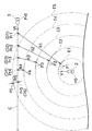
- the obtained predicted position of the other ship 3 serves as a positional reference for determining whether or not the collision danger zone and the caution zone should be displayed at that position. In the following description, this position may be referred to as a determination point.
- the other ship's future position prediction unit 13 starts at a reference time T0 (specifically, the current time), which is the time when the position and speed of the other ship 3 are obtained, as an appropriate time interval.
- T0 specifically, the current time
- a plurality of future times T1, T2, ... are set by opening ⁇ T.
- the other ship future position prediction unit 13 is based on the position and speed of the other ship 3 at the reference time T0 (other ship position Pr0 and other ship speed vector Vt), and the above-mentioned future times T1, T2, ... ⁇ ⁇
- the other ship positions Pr1, Pr2, ... Obtained by the prediction become the determination points D1, D2, ....
- the other ship future position prediction unit 13 determines the magnitude of the other ship speed vector Vt acquired at the reference time T0. It is assumed that the other ship 3 moves from the other ship position Pr0 while keeping the directions constant. That is, the other ship 3 is considered to continue sailing at the same course and the same ship speed as the reference time T0. Therefore, the positions of other ships Pr1, Pr2, ... Can be easily obtained.
- the other ship positions Pr1, Pr2, ... are determined to be arranged at appropriate intervals on the course C, which is a straight line extending the other ship's speed vector Vt from the other ship's position Pr0. ..
- the positions of other vessels Pr1, Pr2, ... are arranged at equal intervals, but this is just an example, and the details will be described later.
- the other ship future position prediction unit 13 transmits the acquired data indicating the positions of the other ship positions Pr1, Pr2, ... (Determination points D1, D2, ...) To the calculation processing unit 31 and the display data generation unit 41. Output.
- the own ship data processing unit 21 acquires the data necessary for displaying the collision danger zone and the warning zone for the own ship 2.
- the own ship data processing unit 21 includes a own ship data acquisition unit 22 and a own ship future position prediction unit 23.
- Own ship position P0 is the current position of own ship 2.
- a GNSS positioning device (not shown) is connected to the ship maneuvering support device 1, and the own ship data acquisition unit 22 uses the own ship position P0, which is the position of the own ship 2, based on the positioning result input from the GNSS positioning device. Can be obtained.
- Own ship speed vector V is the current ship speed of own ship 2.
- the own ship data acquisition unit 22 can acquire the own ship speed vector V, which is the ship speed of the own ship 2, by calculating the change in the position obtained from the GNSS positioning device.
- the own ship position P0 and the own ship speed vector V mean the position and speed of the representative point of the own ship 2, specifically, the place where the GNSS antenna shown in the figure is attached.
- the own ship data acquisition unit 22 outputs the obtained own ship position P0 and own ship speed vector V to the own ship future position prediction unit 23.
- the own ship future position prediction unit 23 predicts the future position of the own ship at a plurality of times T1, T2, ... Explained in the other ship future position prediction unit 13 described above.
- the predicted own ship positions P1, P2, ... Correspond to the other ship positions Pr1, Pr2, ... Predicted by the other ship future position prediction unit 13 at each time T1, T2, ... ..
- the own ship future position prediction unit 23 has a constant magnitude of the own ship speed vector V acquired at the reference time T0, while the own ship speed vector. It is assumed that the direction of V changes to an arbitrary direction at the reference time T0, and after that, the own ship 2 continues to sail from the own ship position P0 in a constant direction. That is, the own ship 2 arbitrarily determines the course at the own ship position P0, but after that, it is considered that the ship 2 continues to sail on the course and at the same ship speed. Therefore, the estimated own ship positions P1, P2, ... Are all located on concentric circles centered on the own ship position P0 at the reference time T0.
- a small circle indicates a part of the positions estimated in large numbers with respect to the own ship positions P1, P2, ....
- the radius of the circle in which the predicted ship positions P1, P2, ... Are lined up (hereinafter, may be referred to as the ship position candidate circles E1, E2, 7) Is from the reference time T0 to each time T1. , T2, ... Is equal to the product of the magnitude of the ship's speed vector V.
- the own ship future position prediction unit 23 in FIG. 1 obtains the own ship position candidate circles E1, E2, ... At each time T1, T2, ....
- the own ship future position prediction unit 23 outputs the data regarding the own ship position candidate circles E1, E2, ... As the predicted own ship positions P1, P2, ... To the calculation processing unit 31.
- the set length storage unit 26 stores the own ship length L and the private length PL.
- the own ship length L is the total length of the own ship 2 in the front-rear direction.
- the master ship length L indicates the physical size of the own ship 2 in the front-rear direction.
- another ship 3 exists within the range of the own ship length L, it is considered that a collision occurs between the own ship 2 and the other ship 3.
- Predicted by the own ship future position prediction unit 23 are the positions where the above-mentioned GNSS antenna is attached to the hull. This position (the above-mentioned representative point, hereinafter referred to as the own ship reference position) is usually in the middle of the own ship length L.
- the parameter of the own ship length L is a combination of the above-mentioned length L1 from the own ship reference position to the bow and the length L2 from the own ship reference position to the stern.
- the two lengths L1 and L2 are appropriately set in advance in the ship maneuvering support device 1.
- the private length PL is not included in the above-mentioned own ship length L, physical contact between the own ship 2 and the other ship 3 does not occur, but the invasion of the other ship 3 is psychologically unfavorable. It means the length of the private area (warning area) felt by the operator in the front-back direction.
- the private area can be likened to a personal area that raises alertness when another person gets closer to or behind you when considering the distance between people.
- the private length PL is set to at least one of the front side and the rear side of the own ship length L by the operator at an arbitrary length. For example, the operator can set a private length PL with a length of 0.5 nautical mile on the front side of his own captain L.
- the set length storage unit 26 shown in FIG. 1 outputs the stored ship length L and private length PL to the calculation processing unit 31.
- the calculation processing unit 31 uses the data output from the other ship data processing unit 11 and the own ship data processing unit 21 to set a collision danger zone or a warning zone at each of the above-mentioned determination points D1, D2, ... Whether or not to display is determined by calculation.
- the calculation processing unit 31 includes a separation distance calculation unit 32, a risk calculation unit 33, and a zone display determination unit 34.
- the separation distance calculation unit 32 sets the other ship positions Pr1, Pr2, ... That are predicted to reach at each time T1, T2, ... In the future, and the corresponding own ship positions P1, P2, ... -Calculate the separation distances R1, R2, ..., Which is the distance between and.
- the separation distance calculation unit 32 is the position closest to the other ship position Pr1 at the time T1 among the many predicted own ship positions P1 at the time T1.
- the own ship position P1 selected for the calculation of the separation distance R1 from the large number of predicted own ship positions P1 is indicated by a black circle.
- the separation distance R1 is calculated as the distance between the position marked with a black circle in the own ship position P1 and the other ship position Pr1.
- the separation distance R1 means the minimum value of the distance between the point on the own ship position candidate circle E1 and the other ship position Pr1.
- the separation distance R1 at the time T1 is the distance between the other ship position Pr1 at the time T1 and the own ship position P0 (the center of the own ship position candidate circle E1) at the reference time T0. It can be easily obtained by subtracting the radius of the ship position candidate circle E1. The same applies to the separation distances R2, ... At other times T2, ...
- the separation distance calculation unit 32 considers the ship speeds of the own ship 2 and the other ship 3 to be constant, and is the distance between the predicted future position of the own ship 2 and the future position of the other ship 3.
- the separation distance Rn is calculated. Therefore, the separation distance Rn can be obtained by a simple geometric calculation.
- the separation distance Rn is obtained by the above calculation method, the value can be negative as well as positive.
- the separation distance Rn is positive, it means that the own ship position Pn is closer to the own ship position P0 at the reference time T0 than the other ship position Prn.
- the separation distance Rn is negative, it means that the own ship position Pn is farther from the own ship position P0 at the reference time T0 than the other ship position Prn.
- the separation distances R1, R2, R3, and R4 are positive, and the separation distance R5 is negative.
- the separation distance Rn When the separation distance Rn is positive, it means that the other ship 3 is on the bow side of the own ship 2 in the case where the own ship 2 and the other ship 3 are closest to each other.
- the separation distance Rn When the separation distance Rn is negative, it means that the other ship 3 is on the stern side of the own ship 2 in the case where the own ship 2 and the other ship 3 are closest to each other.
- both the own ship 2 and the other ship 3 are treated as points, and the physical size is not considered.
- the separation distance Rn is expressed as the distance between the reference position of the own ship, which is the representative point of the own ship 2, and the representative point of the other ship 3.
- the risk calculation unit 33 in FIG. 1 calculates the risk value (collision risk value, warning risk value) RPn, which is a parameter for determining whether to display the collision danger zone and the caution zone. Specifically, the risk calculation unit 33 uses a predetermined risk function FR to convert each separation distance Rn calculated by the separation distance calculation unit 32 into a risk value RPn.
- the risk value RPn is a value of 0 or more and 1 or less, 0 indicates that there is no possibility of collision between the own ship 2 and the other ship 3, and 1 indicates that the own ship 2 and the other ship 3 collide. ..
- the risk function FR used by the risk calculation unit 33 for the calculation is determined by referring to the storage contents of the set length storage unit 26.
- the risk function FR used in the present embodiment has the origin of the ship's reference position in FIG. 3A, the separation distance R on the horizontal axis, and the risk value RP on the vertical axis. It is shown by the graph.
- the risk calculation unit 33 calculates the risk value RP by using the risk function FR in which the value becomes 1 in the range where the separation distance R corresponds to the own ship length L. Therefore, the possibility of collision can be evaluated in consideration of the physical length of the own ship.
- the risk calculation unit 33 outputs the risk values RP1, RP2, ... Obtained by substituting the separation distances R1, R2, ... To the above risk function FR to the zone display determination unit 34.
- the zone display determination unit 34 outputs from the risk calculation unit 33 whether the collision danger zone should be displayed, the caution zone should be displayed, or neither should be displayed at the respective determination points D1, D2, ... Judgment is made according to the risk values RP1, RP2, ...
- the zone display determination unit 34 determines that it is necessary to display the collision risk zone when the risk value RPn output from the risk calculation unit 33 is 1.
- the zone display determination unit 34 determines that it is necessary to display the caution zone when the risk value RP output from the risk value RP is smaller than 1 but larger than 0.
- the zone display determination unit 34 determines that neither the collision danger zone nor the warning zone needs to be displayed.
- the calculation processing unit 31 of the present embodiment does not calculate the probability distribution in consideration of the speed error as used in the conventional OZT. That is, the calculation processing unit 31 simply considers that there is no error in the own ship speed vector V and the other ship speed vector Vt, and simply sets the reference position of the own ship 2 indicated by the separation distance Rn and the other ship. Display of collision danger zone and warning zone based on whether or not the positional relationship with the representative point of 3 is included in the range of own ship length L or within the range of private length PL. Judging the necessity. Therefore, the amount of calculation required for judgment can be significantly reduced.
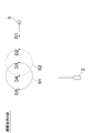
- FIG. 4 is a diagram showing a display example of the collision danger zone 91 and the warning zone 92 in the situation of FIG.
- FIG. 5 is a diagram showing the display of the collision danger zone 91 and the warning zone 92 according to the present embodiment in comparison with the display of the conventional OZT.
- the display data generation unit 41 generates display data for displaying information for supporting the operator on the display device 5, and outputs the display data to the display device 5 via an appropriate interface.
- the risk value RP4 corresponding to the separation distance R4 is 1, the risk value corresponding to the separation distance R3 is 0.3, and the other separation distances R1, R2, and R5 are shown.
- a display example of the display device 5 is shown when the corresponding risk values are all 0.
- a figure indicating a collision danger zone 91 is displayed at the determination point D4, and a figure indicating a caution zone 92 is displayed at the determination point D3.
- No figures are displayed at the other determination points D1, D2, and D5. Since the determination points D1, D2, ... Are points used as a reference for calculation, they are drawn in FIG. 4 for explanation, but are not actually displayed on the screen.
- the collision danger zone 91 and the caution zone 92 are displayed as a circular figure centered on the determination point Dn.
- the size of the circle is appropriately determined so that it does not become too small.
- the size of a circle can be determined so that its diameter is equal to its own captain L.
- the own ship position P0, the own ship speed vector V, the other ship position Pr0, and the other ship speed vector Vt input to the ship maneuvering support device 1 change from moment to moment, and the collision danger zone 91 and the warning are given accordingly. It is necessary to update the display of zone 92 in real time. Further, it is conceivable that there are not only one other ship 3 but also a plurality of other ships 3 around the own ship 2. In this case, the collision danger zone 91 and the warning zone 92 must be displayed for each of the other ships 3. Must be. Therefore, it is important to reduce the computational load required for processing.
- the future position prediction unit 13 of another ship can theoretically generate an infinite number of judgment points Dn, but when the number of judgment points Dn becomes large, the calculation load becomes heavy. Therefore, in the present embodiment, a predetermined determination limit distance is set, and the position of the determination point Dn output by the future position prediction unit 13 of the other ship is limited to within the determination limit distance from the position Pr0 of the other ship. This makes it possible to prevent the calculation load from becoming excessive.
- the amount of calculation required to determine whether or not the collision danger zone 91 and the caution zone 92 should be displayed at each determination point Dn is reduced as compared with the conventional case. .. Therefore, even when a large number of judgment points Dn are generated by shortening the distance between adjacent judgment points Dn or lengthening the judgment limit distance, processing can be performed in real time without any problem. .. As a result, the resolution at which the collision danger zone 91 and the warning zone 92 are displayed can be increased, or the collision danger zone 91 and the warning zone 92 can be displayed based on the future prediction.
- the colors displayed on the display device 5 can be made different between the collision danger zone 91 and the caution zone 92.
- the solid line and the broken line show that the display colors are different between the collision danger zone 91 and the caution zone 92.
- the operator clearly defines the area where a collision with the other ship 3 is likely to occur and the area where the other ship 3 is likely to enter the above-mentioned private length PL without collision. Since it is possible to distinguish and grasp the situation, the situation can be easily understood.
- how to change the display between the collision danger zone 91 and the caution zone 92 in the display device is not limited to changing the color.
- the collision danger zone 91 and the caution zone 92 it is possible to display whether or not the interior is filled, and the transparency and pattern of the filled portion are changed.
- the outline of the zone figure may be different between the solid line and the broken line.
- a character, a number, a small mark, or the like may be added to the figure of the zone so that the operator can distinguish between the collision danger zone 91 and the caution zone 92.
- the warning zone 92 corresponds to the case where the risk value RP is larger than 0 and smaller than 1, but the display data generation unit 41 displays the warning zone 92 in a different display mode depending on the size of the risk value RP. Data may be generated. For example, as the risk value RP decreases, it is conceivable to gradually increase the transparency of the displayed outline or internal fill of the alert zone 92. Further, the collision danger zone 91 may be displayed in red, and the caution zone 92 may be displayed by changing the color so as to gradually change from red to yellow as the risk value RP becomes smaller.
- the warning zone is displayed uniformly when the risk value RP is greater than 0 and less than 1, but may be displayed only when the risk value RP is larger than the predetermined threshold set by the operator. good. As a result, it is possible to realize a display according to the preference of the ship operator.
- the collision danger zone 91 and the caution zone 92 can be displayed in exactly the same manner.
- the risk of collision is evaluated in consideration of the captain L in the risk function FR. That is, the own ship 2 is not treated as a point, but is treated as a straight line elongated by the length L of the own ship in the front-rear direction. Therefore, for example, even in the case of a large ship having a considerably long own ship length L, the area where there is a high risk of collision can be displayed at an appropriate position in consideration of the actual size of the ship.
- FIG. 5 shows a comparison of the display of the collision risk zone 91 of the present embodiment and the conventional OZT under the same circumstances.
- the collision danger zone 91 of the present embodiment is closer to the other ship 3 than the conventional OZT shown in FIG. 5 (b) by considering the own ship length L.
- the area of the zone is expanded (extended part 91e).
- the own ship 2 is displayed not only on the part that overlaps with the conventional OZT but also on the extended part 91e that extends from it. Indicates that the ship should not be maneuvered.
- the warning zone 92 associated with setting the private length PL in front of the own ship 2 is displayed closer to the other ship 3 than the collision danger zone 91. Will be done. This display indicates that when the ship is maneuvered in the caution zone 92, there is a high possibility that the other ship 3 will enter the area corresponding to the private length PL in front of the own ship 2.
- the collision danger zone 91 is not displayed in the place N1 corresponding to the leftmost circle of the conventional OZT shown in FIG. 5 (b).
- the example of FIG. 5A shows a case where the private length PL is not set behind the own ship 2, but if the private length PL behind is set appropriately, the caution zone 92 is set in the above-mentioned place N1. Will be displayed.
- the position of the radar antenna provided in the radar device is assumed to be the same as the position of the GNSS antenna of the GNSS positioning device (in other words, the reference position of the own ship), and the collision risk is evaluated. ..
- the reference position of the own ship may be set so as to match the position of the radar antenna instead of the position of the GNSS antenna. In this case, the position of the own ship acquired by the data processing unit 11 of the other ship is recalculated so that the position of the radar antenna is used as a reference.
- the ship maneuvering support device 1 of the present embodiment includes the other ship data acquisition unit 12, the other ship future position prediction unit 13, the own ship data acquisition unit 22, and the own ship future position prediction unit 23.
- a risk calculation unit 33 and a display data generation unit 41 are provided.
- the other ship data acquisition unit 12 acquires information on the position and speed of the other ship 3 (other ship position Pr0 and other ship speed vector Vt).
- the other ship future position prediction unit 13 navigates the other ship 3 on the same course and at the same ship speed based on the other ship position Pr0 and the other ship speed vector Vt acquired by the other ship data acquisition unit 12. If it continues, the other ship positions Pr1, Pr2, ... At a plurality of future times T1, T2, ... Are predicted.
- the own ship data acquisition unit 22 acquires information on the position and speed of the own ship 2 (own ship position P0 and own ship speed vector V).
- the own ship future position prediction unit 23 is a course arbitrarily determined by the own ship 2 at the own ship position P0 based on the own ship position P0 and the own ship speed vector V acquired by the own ship data acquisition unit 22. And when sailing is continued at the same ship speed, the own ship positions P1, P2, ... Corresponding to the other ship positions Pr1, Pr2, ... Predicted by the other ship future position prediction unit 13 are predicted. ..
- the risk calculation unit 33 sets the other ship positions Pr1, Pr2, ... Predicted at each time T1, T2, ...
- the display data generation unit 41 generates display data for displaying the collision danger zone 91 at the predicted other ship positions Pr1, Pr2, ... Based on the determination using the risk value RP.
- the collision danger zone 91 which is, can be displayed on the display device 5. That is, since the size of the own ship 2 is taken into consideration, it is possible to display the collision danger zone 91, which is more appropriate and matches the actual feeling of maneuvering the ship. Also, instead of calculating the simultaneous existence probability of the own ship and the other ship in consideration of the occurrence of speed error as in the past, the separation distance between the own ship 2 and the other ship 3 is used as a reference. Since the display determination of the collision danger zone 91 is performed, the calculation load can be significantly reduced.
- FIG. 6 is a block diagram showing an electrical configuration of the ship maneuvering support device 1x of the second embodiment.
- the same reference numerals may be given to the members which are the same as or similar to those of the first embodiment described above, and the description may be omitted.
- the other ship data acquisition unit 12 acquires the position and speed information of the other ship 3 from the AIS device instead of the radar device.
- the AIS device is a ship automatic identification system for exchanging navigation information of a plurality of ships, and acquires data such as the position of another ship 3, the ground speed, the ship name, the length and width of the ship, and the position of the positioning antenna. can do.
- the other ship data acquisition unit 12 acquires not only the position and speed of the other ship 3 but also the length of the other ship 3 and the position information of the positioning antenna in the front-rear direction. Based on the information on the length of the other ship 3 and the position of the positioning antenna, the other ship data acquisition unit 12 determines the length from the position of the positioning antenna of the other ship 3 to the bow and the length from the position of the positioning antenna to the stern. Is output to the risk calculation unit 33.
- the risk calculation unit 33 uses the own ship length L and private length PL acquired from the set length storage unit 26 and the length of the other ship acquired from the other ship data acquisition unit 12 to obtain the risk value RP. calculate.
- the risk function FR used in the present embodiment with respect to the graph of FIG. 3B, the region of the separation distance R at which the risk value RP becomes 1 is set in consideration of the length of the other ship 3 and the own ship 2 It may be changed so as to expand appropriately in the front-back direction of.
- the display of the collision danger zone 91 and the warning zone 92 can be made more consistent with the actual feeling of maneuvering by the operator.
- the information on the other ship 3 obtained by AIS may not include information on the size of the other ship 3.
- the risk calculation unit 33 can uniformly consider the length of the other vessel 3 to be equal to the length appropriately set in advance by the operator, and calculate the risk value RP.
- the other ship positions Pr1, Pr2, ... (Determining points D1, D2, 7) Determined by the other ship future position prediction unit 13 are arranged at equal intervals on the course C of the other ship position Pr0 as shown in FIG. It is not limited to this, and can be set at unequal intervals. For example, consider a plurality of virtual straight lines that radiate from the position of the own ship 2 at equal angle intervals, and the other ship positions Pr1, Pr2, ... Are determined at the positions where the respective virtual straight lines intersect the above-mentioned needle path C. May be done.
- the angle interval of the virtual straight line close to the current course of the own ship 2 (for example, the virtual straight line within 10 ° to the left and right from the course of the own ship 2) is smaller than the angular interval of the virtual straight line not.
- Multiple virtual straight lines can be placed.
- the determination points D1, D2, ... Can be determined closely in the area where the current course of the own ship 2 is likely to interfere, the collision danger zone and the warning zone are displayed in the vicinity of the planned course of the own ship 2. Spatial resolution can be increased.
- the other ship positions Pr1, Pr2, ... Correspond to a plurality of future times T1, T2, .... Therefore, the size of the corresponding own ship position candidate circles E1, E2, ... Also changes depending on how the other ship positions Pr1, Pr2, ... Are determined.
- the own ship reference position is not limited to the position described in the above embodiment, and can be set at any point on the own ship 2.
- the reference position of the own ship can be set to the position that becomes the axis when the own ship 2 is turning (the position of the turning center in the ship motion).
- the private length PL set particularly on the front side of the own ship 2 may be configured to automatically change according to the magnitude of the own ship speed vector V.
- the other ship data processing unit 11 determines the length of the other ship 3 acquired from the shape of the echo image tracked by the TT function in the radar device described in the first embodiment instead of the AIS. It can also be configured to get.
- the display of the collision danger zone 91 can be determined by considering not only the length of the own ship 2 but also the width.
- the display of the alert zone 92 can be determined by considering not only the length of the private area but also the width of the private area. Similarly, not only the length of the other ship 3 but also the width can be considered.
- the risk value for determining whether or not to display the collision risk zone 91 (collision risk value) and the risk value for determining whether or not to display the caution zone 92 (warning risk value) are common risks. It may be obtained by a separate function instead of the function FR.
- the collision danger zone 91 and the caution zone 92 can be displayed in any manner.
- the circle centered on the determination point Dn it may be displayed by a line connecting the determination points Dn. Then, the thickness of the line can be appropriately set.
- the risk value RP in the private length PL may decrease linearly, for example, instead of decreasing linearly as shown in FIG. 3 (b).
- the calculation processing unit 31 calculates the risk value RP in consideration of the physical size of the own ship 2 by the risk calculation unit 33.
- the physical size of the own ship 2 may be taken into consideration at the stage where the separation distance calculation unit 32 calculates the separation distance Rn.
- the separation distance calculation unit 32 considers the length L1 from the reference position of the own ship to the bow, the predicted position of the representative point of the other ship 3, and the predicted tip of the bow of the own ship 2 in the future. It is conceivable to calculate the minimum value of the distance between the position and the position as the separation distance Rn.
- the ship maneuvering support device 1 may integrally include a display device 5.
Landscapes
- Engineering & Computer Science (AREA)
- Radar, Positioning & Navigation (AREA)
- Remote Sensing (AREA)
- Ocean & Marine Engineering (AREA)
- Physics & Mathematics (AREA)
- Mechanical Engineering (AREA)
- Chemical & Material Sciences (AREA)
- Combustion & Propulsion (AREA)
- General Physics & Mathematics (AREA)
- Automation & Control Theory (AREA)
- Computer Networks & Wireless Communication (AREA)
- Public Health (AREA)
- Health & Medical Sciences (AREA)
- Aviation & Aerospace Engineering (AREA)
- Electromagnetism (AREA)
- Traffic Control Systems (AREA)
- Electrical Discharge Machining, Electrochemical Machining, And Combined Machining (AREA)
- Paper (AREA)
Priority Applications (6)
| Application Number | Priority Date | Filing Date | Title |
|---|---|---|---|
| KR1020227028359A KR20220128424A (ko) | 2020-01-20 | 2020-12-23 | 조선 지원 장치 |
| EP20915571.2A EP4095030B1 (en) | 2020-01-20 | 2020-12-23 | Maneuvering assistance device |
| CN202080090828.4A CN114930427B (zh) | 2020-01-20 | 2020-12-23 | 驾船支援装置及驾船支援方法 |
| JP2021573027A JP7635162B2 (ja) | 2020-01-20 | 2020-12-23 | 操船支援装置及び操船支援方法 |
| US17/868,860 US12473059B2 (en) | 2020-01-20 | 2022-07-20 | Ship maneuver supporting device and ship maneuver supporting method |
| JP2025020620A JP7799104B2 (ja) | 2020-01-20 | 2025-02-12 | 操船支援装置及び操船支援方法 |
Applications Claiming Priority (2)
| Application Number | Priority Date | Filing Date | Title |
|---|---|---|---|
| JP2020-007183 | 2020-01-20 | ||
| JP2020007183 | 2020-01-20 |
Related Child Applications (1)
| Application Number | Title | Priority Date | Filing Date |
|---|---|---|---|
| US17/868,860 Continuation-In-Part US12473059B2 (en) | 2020-01-20 | 2022-07-20 | Ship maneuver supporting device and ship maneuver supporting method |
Publications (1)
| Publication Number | Publication Date |
|---|---|
| WO2021149447A1 true WO2021149447A1 (ja) | 2021-07-29 |
Family
ID=76992291
Family Applications (1)
| Application Number | Title | Priority Date | Filing Date |
|---|---|---|---|
| PCT/JP2020/048156 Ceased WO2021149447A1 (ja) | 2020-01-20 | 2020-12-23 | 操船支援装置 |
Country Status (6)
| Country | Link |
|---|---|
| US (1) | US12473059B2 (https=) |
| EP (1) | EP4095030B1 (https=) |
| JP (2) | JP7635162B2 (https=) |
| KR (1) | KR20220128424A (https=) |
| CN (1) | CN114930427B (https=) |
| WO (1) | WO2021149447A1 (https=) |
Cited By (1)
| Publication number | Priority date | Publication date | Assignee | Title |
|---|---|---|---|---|
| CN113744569A (zh) * | 2021-11-03 | 2021-12-03 | 武汉理工大学 | 开阔水域船舶自主避碰方法、系统、设备及存储介质 |
Families Citing this family (6)
| Publication number | Priority date | Publication date | Assignee | Title |
|---|---|---|---|---|
| JP2021142788A (ja) * | 2020-03-10 | 2021-09-24 | トヨタ自動車株式会社 | 運転支援システム |
| EP4234385A4 (en) * | 2020-10-23 | 2024-07-17 | Furuno Electric Co., Ltd. | SHIP SURVEILLANCE SYSTEM, SHIP SURVEILLANCE METHOD, INFORMATION PROCESSING DEVICE AND PROGRAM |
| WO2022249632A1 (ja) * | 2021-05-26 | 2022-12-01 | 古野電気株式会社 | 船舶監視装置、船舶監視方法、及びプログラム |
| EP4290495A1 (en) | 2022-06-09 | 2023-12-13 | Furuno Electric Co., Ltd. | Obstruction zone generation device and method |
| CN116161198B (zh) * | 2023-02-16 | 2025-12-02 | 武汉理工大学 | 一种船舶碰撞数据的多传感器无线采集与传输系统及方法 |
| JP2025119644A (ja) * | 2024-02-02 | 2025-08-15 | 古野電気株式会社 | 航行支援システム、航行支援方法、及びプログラム |
Citations (2)
| Publication number | Priority date | Publication date | Assignee | Title |
|---|---|---|---|---|
| JPS62117100A (ja) * | 1985-11-18 | 1987-05-28 | 日本鋼管株式会社 | 避航判断支援装置 |
| JP2018528508A (ja) * | 2015-07-07 | 2018-09-27 | コリア インスティチュート オブ オーシャン サイエンス アンド テクノロジー | 時系列グラフィック表示を用いた船舶衝突回避案内システム |
Family Cites Families (23)
| Publication number | Priority date | Publication date | Assignee | Title |
|---|---|---|---|---|
| JPH08235500A (ja) * | 1995-02-23 | 1996-09-13 | Oki Electric Ind Co Ltd | 衝突予防支援装置 |
| US5860605A (en) * | 1996-10-11 | 1999-01-19 | Johannes Petrus Andreas Josephus Van Der Zanden | Method and device for synchronously making material collide |
| JP4055915B2 (ja) * | 1997-10-23 | 2008-03-05 | 日本無線株式会社 | 自動衝突予防援助装置 |
| JP3777411B2 (ja) | 2003-08-08 | 2006-05-24 | 今津隼馬 | 船舶航行支援装置 |
| JP4445313B2 (ja) | 2004-04-01 | 2010-04-07 | 古野電気株式会社 | 船舶航行支援装置 |
| US20060290562A1 (en) * | 2005-05-05 | 2006-12-28 | Ehresoft Technologies | Maritime contact management and collison avoidance systems and methods |
| JP4375308B2 (ja) * | 2005-08-30 | 2009-12-02 | 日本電気株式会社 | 隆線方向抽出装置、隆線方向抽出方法、隆線方向抽出プログラム |
| US8423278B2 (en) * | 2008-11-19 | 2013-04-16 | Furuno Electric Company Limited | Navigation aid method, device and program |
| JP5415145B2 (ja) * | 2009-05-13 | 2014-02-12 | 古野電気株式会社 | レーダ装置 |
| JP2011060179A (ja) * | 2009-09-14 | 2011-03-24 | National Institute Of Advanced Industrial Science & Technology | 操舵制御方法 |
| JP2013028296A (ja) | 2011-07-29 | 2013-02-07 | Ship & Ocean Foundation | 船舶用航行支援装置 |
| US10431099B2 (en) * | 2014-02-21 | 2019-10-01 | FLIR Belgium BVBA | Collision avoidance systems and methods |
| JP2017041071A (ja) * | 2015-08-19 | 2017-02-23 | 古野電気株式会社 | 船舶用表示装置 |
| CN105184480A (zh) * | 2015-09-01 | 2015-12-23 | 中国南方电网有限责任公司超高压输电公司广州局 | 一种船舶对海缆的潜在锚害的评估方法及管控系统 |
| JP6953108B2 (ja) * | 2015-09-08 | 2021-10-27 | 古野電気株式会社 | 情報表示装置及び情報表示方法 |
| US11262449B2 (en) * | 2016-05-26 | 2022-03-01 | Furuno Electric Co., Ltd. | Signal processing device and radar device |
| WO2018193596A1 (ja) * | 2017-04-20 | 2018-10-25 | 富士通株式会社 | 衝突リスク算出プログラム、衝突リスク算出方法および衝突リスク算出装置 |
| KR101902730B1 (ko) * | 2018-02-12 | 2018-09-28 | 목포해양대학교 산학협력단 | 해기사의 심리적 특성을 이용한 선박의 충돌 회피 방법 |
| JP6618562B2 (ja) * | 2018-03-22 | 2019-12-11 | 東京計器株式会社 | 船舶用航行支援装置 |
| CN108711312B (zh) * | 2018-05-24 | 2020-09-01 | 大连海事大学 | 基于bp神经网络的船舶与静态物标碰撞风险预判方法 |
| JP6901431B2 (ja) | 2018-05-25 | 2021-07-14 | 株式会社本間組 | 工事船舶運航管理システム |
| JP7138706B2 (ja) * | 2018-07-06 | 2022-09-16 | 古野電気株式会社 | 表示データ生成装置 |
| JP2025117100A (ja) | 2024-01-30 | 2025-08-12 | 株式会社Magnolia White | ストレッチャブルデバイス |
-
2020
- 2020-12-23 JP JP2021573027A patent/JP7635162B2/ja active Active
- 2020-12-23 CN CN202080090828.4A patent/CN114930427B/zh active Active
- 2020-12-23 EP EP20915571.2A patent/EP4095030B1/en active Active
- 2020-12-23 WO PCT/JP2020/048156 patent/WO2021149447A1/ja not_active Ceased
- 2020-12-23 KR KR1020227028359A patent/KR20220128424A/ko active Pending
-
2022
- 2022-07-20 US US17/868,860 patent/US12473059B2/en active Active
-
2025
- 2025-02-12 JP JP2025020620A patent/JP7799104B2/ja active Active
Patent Citations (2)
| Publication number | Priority date | Publication date | Assignee | Title |
|---|---|---|---|---|
| JPS62117100A (ja) * | 1985-11-18 | 1987-05-28 | 日本鋼管株式会社 | 避航判断支援装置 |
| JP2018528508A (ja) * | 2015-07-07 | 2018-09-27 | コリア インスティチュート オブ オーシャン サイエンス アンド テクノロジー | 時系列グラフィック表示を用いた船舶衝突回避案内システム |
Non-Patent Citations (2)
| Title |
|---|
| HAYAMA IMAZUJUNJI FUKUTOMASAYOSHI NUMANO: "Obstacle Zone by Target and its Expression", THE JOURNAL OF JAPAN INSTITUTE OF NAVIGATION, vol. 107, September 2002 (2002-09-01), pages 191 - 197 |
| See also references of EP4095030A4 |
Cited By (1)
| Publication number | Priority date | Publication date | Assignee | Title |
|---|---|---|---|---|
| CN113744569A (zh) * | 2021-11-03 | 2021-12-03 | 武汉理工大学 | 开阔水域船舶自主避碰方法、系统、设备及存储介质 |
Also Published As
| Publication number | Publication date |
|---|---|
| JP7635162B2 (ja) | 2025-02-25 |
| EP4095030A4 (en) | 2024-01-24 |
| CN114930427B (zh) | 2025-10-28 |
| JPWO2021149447A1 (https=) | 2021-07-29 |
| CN114930427A (zh) | 2022-08-19 |
| EP4095030A1 (en) | 2022-11-30 |
| EP4095030B1 (en) | 2025-07-09 |
| JP7799104B2 (ja) | 2026-01-14 |
| US20220348297A1 (en) | 2022-11-03 |
| US12473059B2 (en) | 2025-11-18 |
| KR20220128424A (ko) | 2022-09-20 |
| JP2025067946A (ja) | 2025-04-24 |
Similar Documents
| Publication | Publication Date | Title |
|---|---|---|
| WO2021149447A1 (ja) | 操船支援装置 | |
| US10317513B2 (en) | Method and device for displaying information | |
| JP6661745B2 (ja) | 時系列グラフィック表示を用いた船舶衝突回避案内システム | |
| JP2012021947A (ja) | 航行援助装置 | |
| KR102495879B1 (ko) | 라이다를 이용한 선박 제어 시스템 | |
| JP7431194B2 (ja) | 拡張現実に基づく潮流表示装置 | |
| JP2024007541A (ja) | 航路計画システムおよび航路計画方法 | |
| JP7781866B2 (ja) | 船舶監視システム、船舶監視方法、情報処理装置、及びプログラム | |
| JP7636957B2 (ja) | 操船支援システム、操船支援方法、情報処理装置、及びプログラム | |
| CN120431766A (zh) | 航路计划系统及航路计划方法 | |
| JP7372370B2 (ja) | 情報表示装置及び情報表示方法 | |
| KR20240142775A (ko) | 모바일 기기를 이용한 자율 운항 시스템 | |
| JP2023084024A (ja) | 船舶航行支援装置、船舶航行支援方法、プログラム | |
| US20260062103A1 (en) | Mapping surroundings of a marine vessel | |
| US12391346B2 (en) | Obstruction zone generation device and method | |
| WO2024057826A1 (en) | Navigation supporting device, navigation supporting system, navigation supporting method, and navigation supporting program | |
| JP7489289B2 (ja) | 航路演算装置 | |
| JP2001264414A (ja) | 探査装置の表示装置 | |
| US20250201130A1 (en) | Navigation assistance device and navigation assistance method | |
| US20250198764A1 (en) | Navigation assistance device and navigation assistance method | |
| JPH09257918A (ja) | 航行安全支援装置 | |
| JP2022163993A (ja) | 操船支援装置および操船支援プログラム | |
| WO2024053524A1 (ja) | 航行支援装置、航行支援方法 | |
| JP2011086196A (ja) | 画像表示装置、画像表示方法、および画像表示プログラム |
Legal Events
| Date | Code | Title | Description |
|---|---|---|---|
| 121 | Ep: the epo has been informed by wipo that ep was designated in this application |
Ref document number: 20915571 Country of ref document: EP Kind code of ref document: A1 |
|
| ENP | Entry into the national phase |
Ref document number: 2021573027 Country of ref document: JP Kind code of ref document: A |
|
| NENP | Non-entry into the national phase |
Ref country code: DE |
|
| ENP | Entry into the national phase |
Ref document number: 2020915571 Country of ref document: EP Effective date: 20220822 |
|
| WWG | Wipo information: grant in national office |
Ref document number: 2020915571 Country of ref document: EP |
|
| WWG | Wipo information: grant in national office |
Ref document number: 202080090828.4 Country of ref document: CN |