WO2021141110A1 - ベーパーチャンバ用のウィックシート、ベーパーチャンバおよび電子機器 - Google Patents
ベーパーチャンバ用のウィックシート、ベーパーチャンバおよび電子機器 Download PDFInfo
- Publication number
- WO2021141110A1 WO2021141110A1 PCT/JP2021/000478 JP2021000478W WO2021141110A1 WO 2021141110 A1 WO2021141110 A1 WO 2021141110A1 JP 2021000478 W JP2021000478 W JP 2021000478W WO 2021141110 A1 WO2021141110 A1 WO 2021141110A1
- Authority
- WO
- WIPO (PCT)
- Prior art keywords
- flow path
- sheet
- steam flow
- groove
- steam
- Prior art date
- Legal status (The legal status is an assumption and is not a legal conclusion. Google has not performed a legal analysis and makes no representation as to the accuracy of the status listed.)
- Ceased
Links
Images













Classifications
-
- H—ELECTRICITY
- H05—ELECTRIC TECHNIQUES NOT OTHERWISE PROVIDED FOR
- H05K—PRINTED CIRCUITS; CASINGS OR CONSTRUCTIONAL DETAILS OF ELECTRIC APPARATUS; MANUFACTURE OF ASSEMBLAGES OF ELECTRICAL COMPONENTS
- H05K7/00—Constructional details common to different types of electric apparatus
- H05K7/20—Modifications to facilitate cooling, ventilating, or heating
- H05K7/2029—Modifications to facilitate cooling, ventilating, or heating using a liquid coolant with phase change in electronic enclosures
- H05K7/20336—Heat pipes, e.g. wicks or capillary pumps
-
- F—MECHANICAL ENGINEERING; LIGHTING; HEATING; WEAPONS; BLASTING
- F28—HEAT EXCHANGE IN GENERAL
- F28D—HEAT-EXCHANGE APPARATUS, NOT PROVIDED FOR IN ANOTHER SUBCLASS, IN WHICH THE HEAT-EXCHANGE MEDIA DO NOT COME INTO DIRECT CONTACT
- F28D15/00—Heat-exchange apparatus with the intermediate heat-transfer medium in closed tubes passing into or through the conduit walls ; Heat-exchange apparatus employing intermediate heat-transfer medium or bodies
- F28D15/02—Heat-exchange apparatus with the intermediate heat-transfer medium in closed tubes passing into or through the conduit walls ; Heat-exchange apparatus employing intermediate heat-transfer medium or bodies in which the medium condenses and evaporates, e.g. heat pipes
-
- F—MECHANICAL ENGINEERING; LIGHTING; HEATING; WEAPONS; BLASTING
- F28—HEAT EXCHANGE IN GENERAL
- F28D—HEAT-EXCHANGE APPARATUS, NOT PROVIDED FOR IN ANOTHER SUBCLASS, IN WHICH THE HEAT-EXCHANGE MEDIA DO NOT COME INTO DIRECT CONTACT
- F28D15/00—Heat-exchange apparatus with the intermediate heat-transfer medium in closed tubes passing into or through the conduit walls ; Heat-exchange apparatus employing intermediate heat-transfer medium or bodies
- F28D15/02—Heat-exchange apparatus with the intermediate heat-transfer medium in closed tubes passing into or through the conduit walls ; Heat-exchange apparatus employing intermediate heat-transfer medium or bodies in which the medium condenses and evaporates, e.g. heat pipes
- F28D15/04—Heat-exchange apparatus with the intermediate heat-transfer medium in closed tubes passing into or through the conduit walls ; Heat-exchange apparatus employing intermediate heat-transfer medium or bodies in which the medium condenses and evaporates, e.g. heat pipes with tubes having a capillary structure
-
- H—ELECTRICITY
- H10—SEMICONDUCTOR DEVICES; ELECTRIC SOLID-STATE DEVICES NOT OTHERWISE PROVIDED FOR
- H10W—GENERIC PACKAGES, INTERCONNECTIONS, CONNECTORS OR OTHER CONSTRUCTIONAL DETAILS OF DEVICES COVERED BY CLASS H10
- H10W40/00—Arrangements for thermal protection or thermal control
- H10W40/70—Fillings or auxiliary members in containers or in encapsulations for thermal protection or control
- H10W40/73—Fillings or auxiliary members in containers or in encapsulations for thermal protection or control for cooling by change of state
Definitions
- the present invention relates to a wick sheet for a vapor chamber, a vapor chamber and an electronic device.
- Electronic devices that generate heat are used in electronic devices such as mobile terminals.
- this electronic device include a central processing unit (CPU), a light emitting diode (LED), a power semiconductor, and the like.
- Examples of mobile terminals include mobile terminals, tablet terminals, and the like.
- Such an electronic device is cooled by a heat radiating device such as a heat pipe (see, for example, Patent Document 1).
- a heat radiating device such as a heat pipe
- a vapor chamber that can be made thinner than a heat pipe is being developed. The vapor chamber cools the electronic device by absorbing and diffusing the heat of the electronic device by the working fluid enclosed in the vapor chamber.
- the working fluid in the vapor chamber receives heat from the electronic device in a portion (evaporation part) close to the electronic device.
- the working fluid evaporates and changes into working steam.
- the working steam diffuses and is cooled in the steam flow path portion formed in the vapor chamber in a direction away from the evaporation portion.
- the working vapor condenses and changes into a working liquid.
- a liquid flow path portion as a capillary structure also referred to as a wick
- the hydraulic fluid enters the liquid flow path portion from the vapor flow path portion. After that, the hydraulic fluid flows through the liquid flow path portion and is transported toward the evaporation portion.
- the hydraulic fluid transported to the evaporation section receives heat again in the evaporation section and evaporates.
- the working fluid refluxes in the vapor chamber while repeating phase changes, that is, evaporation and condensation.
- the heat of the electronic device is diffused.
- the heat dissipation efficiency of the vapor chamber is improved.
- An object of the present invention is to provide a wick sheet, a vapor chamber and an electronic device for a vapor chamber that can improve heat dissipation efficiency.
- the present invention provides as a first solution.
- a wick sheet for the vapor chamber interposed between the first sheet and the second sheet of the vapor chamber in which the working fluid is sealed.
- a seat body having a first body surface and a second body surface provided on a side opposite to the first body surface.
- a first steam flow path portion extending from the first main body surface of the seat main body to the second main body surface and through which steam of the working fluid passes.
- a liquid flow path portion provided on the surface of the second main body and communicating with the first vapor flow path portion to allow the liquid of the working fluid to pass through.
- the seat body has a land portion having a longitudinal direction in the first direction and a land portion in which the first steam flow path portion is arranged around the seat body.
- the second steam flow path portion is a wick for a vapor chamber having a steam flow path groove extending from one side edge of the land portion to the other side edge in a second direction orthogonal to the first direction. Sheet, I will provide a.
- the second steam flow path portion has a plurality of the steam flow path grooves.
- a steam flow path convex portion that abuts on the first sheet is provided between the pair of steam flow path grooves that are adjacent to each other. You may do so.
- the second steam flow path portion has a steam flow path connecting groove provided on the convex portion of the steam flow path and communicating with a pair of the steam flow path grooves adjacent to each other. You may do so.
- the seat body has a plurality of the land portions and has a plurality of land portions.
- the second steam flow path portion is provided in each of the land portions.
- the steam flow path groove of one of the land portions of the pair of land portions adjacent to each other in the second direction and the steam flow path groove of the other land portion are viewed along the second direction. It is placed in a position where it overlaps when You may do so.
- the second steam flow path portion may be arranged on one side of the land portion in the first direction.
- a communication portion provided on the sheet body and communicating with the liquid flow path portion and the second vapor flow path portion is further provided. You may do so.
- the communication portion includes a through hole that penetrates the sheet body and extends from the liquid flow path portion to the vapor flow path groove. You may do so.
- the liquid flow path portion communicates with a plurality of liquid flow path main flow grooves extending in the first direction and through which the liquid of the working fluid passes, and the liquid flow path main flow groove extending in a direction different from the first direction.
- Has a flow path connecting groove The liquid flow path main flow groove further includes a liquid flow path intersection communicating with the liquid flow path communication groove. The through hole extends to the liquid flow path intersection and the vapor flow path groove. You may do so.
- the present invention provides a second solution.
- a wick sheet for the vapor chamber interposed between the first sheet and the second sheet of the vapor chamber in which the working fluid is sealed.
- a seat body having a first body surface and a second body surface provided on a side opposite to the first body surface.
- a through space extending from the first main body surface of the seat main body to the second main body surface, and A first main body surface groove portion provided on the first main body surface and communicating with the through space, and a groove portion on the first main body surface.
- a second main body surface groove portion provided on the second main body surface and communicating with the through space is provided.
- the seat body has a land portion having a longitudinal direction in the first direction and a land portion in which the penetration space is arranged around the seat body.
- the first main body surface groove portion has a first groove extending from one side edge of the land portion to the other side edge in a second direction orthogonal to the first direction.
- the second main body surface groove portion has a second groove extending in the first direction.
- a wick sheet for a vapor chamber is provided in which the dimension of the first groove in the first direction is larger than the dimension of the second groove in the second direction.
- the present invention provides as a third solution.
- the first sheet and The second sheet and A vapor chamber comprising a wick sheet for a vapor chamber according to the first solution or the second solution described above, interposed between the first sheet and the second sheet. I will provide a.
- the present invention provides as a fourth solution.
- the second steam flow path portion is a vapor chamber, which is arranged in the evaporation region. I will provide a.
- the present invention provides as a fifth solution.
- An electronic device comprising a vapor chamber according to a third or fourth solution described above that is in thermal contact with the device. I will provide a.
- heat dissipation efficiency can be improved.
- FIG. 1 is a schematic perspective view illustrating an electronic device according to an embodiment of the present invention.
- FIG. 2 is a top view showing a vapor chamber according to an embodiment of the present invention.
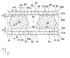
- FIG. 3 is a cross-sectional view taken along the line AA showing the vapor chamber of FIG.
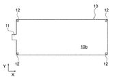
- FIG. 4 is a top view of the lower sheet of FIG.
- FIG. 5 is a bottom view of the upper sheet of FIG.
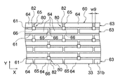
- FIG. 6 is a top view of the wick sheet of FIG.
- FIG. 7 is a bottom view of the wick sheet of FIG.
- FIG. 8 is a partially enlarged cross-sectional view of FIG.
- FIG. 9 is a partially enlarged top view of the liquid flow path portion shown in FIG. FIG.
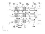
- FIG. 10 is a partially enlarged bottom view of the second steam flow path portion shown in FIG. 7.
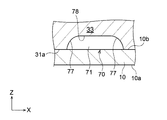
- FIG. 11A is a diagram showing a partial cross section along the line BB of FIG. 7 together with the lower sheet.
- FIG. 11B is a partial cross-sectional view showing a modified example of FIG. 11A.
- FIG. 11C is a partial cross-sectional view showing another modification of FIG. 11A.
- FIG. 12 is a diagram for explaining a wick sheet preparation step in the method for manufacturing a vapor chamber according to an embodiment.
- FIG. 13 is a diagram for explaining an etching process in the method for manufacturing a vapor chamber according to an embodiment.
- FIG. 14 is a diagram for explaining a joining step in the method for manufacturing a vapor chamber according to an embodiment.
- FIG. 11A is a diagram showing a partial cross section along the line BB of FIG. 7 together with the lower sheet.
- FIG. 11B is a partial cross-sectional view showing a modified example of FIG. 11A
- FIG. 15 is a partially enlarged bottom view showing a second steam flow path portion as a first modification.
- FIG. 16A is a partially enlarged bottom view showing the second steam flow path portion as a second modification.
- 16B is a partially enlarged bottom view of FIG. 16A.
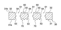
- FIG. 16C is a cross-sectional view taken along the line CC of FIG. 16B.
- FIG. 17 is a partially enlarged bottom view showing the second steam flow path portion as a third modification.
- FIG. 18 is a partially enlarged bottom view showing the second steam flow path portion as a fourth modification.
- FIG. 19 is a partially enlarged top view showing the liquid flow path portion as a fifth modification.
- FIG. 20 is a partially enlarged bottom view showing the second steam flow path portion as a sixth modification.
- FIG. 21 is a partially enlarged bottom view showing the second steam flow path portion as a seventh modification.
- the geometric conditions, the physical properties, the terms that specify the degree of the geometric conditions or the physical properties, the numerical values indicating the geometric conditions or the physical properties, etc. are strictly referred to. I will interpret it without being bound by meaning. Then, these geometric conditions, physical characteristics, terms, numerical values, etc. shall be interpreted including the range in which similar functions can be expected. Examples of terms that specify geometric conditions include “length”, “angle”, “shape” or “arrangement”. Examples of terms that specify geometric conditions include “parallel”, “orthogonal”, “identical”, and the like. Further, in order to clarify the drawing, the shapes of a plurality of parts that can be expected to have the same function are regularly described.
- the shapes of the portions may be different from each other within the range in which the function can be expected.
- the boundary line indicating the joint surface between members is shown by a simple straight line for convenience, but it is not limited to a strict straight line and is within a range in which desired joining performance can be expected.
- the shape of the boundary line is arbitrary.
- the wick sheet for the vapor chamber, the vapor chamber, and the electronic device according to the embodiment of the present invention will be described with reference to FIGS. 1 to 21.
- the vapor chamber 1 in the present embodiment is housed in the housing H of the electronic device E together with the electronic device D that generates heat, and is a device for cooling the electronic device D.
- Examples of the electronic device E include mobile terminals such as mobile terminals and tablet terminals.
- Examples of the electronic device D include a central processing unit (CPU), a light emitting diode (LED), a power semiconductor, and the like.
- the electronic device D may be referred to as a device to be cooled.
- the electronic device E on which the vapor chamber 1 according to the present embodiment is mounted will be described by taking a tablet terminal as an example.
- the electronic device E includes a housing H, an electronic device D housed in the housing H, and a vapor chamber 1.
- a touch panel display TD is provided on the front surface of the housing H.
- the vapor chamber 1 is housed in the housing H and is arranged so as to be in thermal contact with the electronic device D.
- the vapor chamber 1 can receive the heat generated by the electronic device D when the electronic device E is used.
- the heat received by the vapor chamber 1 is released to the outside of the vapor chamber 1 via the working fluids 2a and 2b described later. In this way, the electronic device D is effectively cooled.
- the electronic device D corresponds to a central processing unit or the like.
- the vapor chamber 1 As shown in FIGS. 2 and 3, the vapor chamber 1 has a sealed space 3 in which working fluids 2a and 2b are sealed, and the working fluids 2a and 2b in the sealed space 3 repeatedly undergo phase changes.
- the electronic device D of the electronic device E described above is cooled.
- the working fluids 2a and 2b include pure water, ethanol, methanol, acetone and the like, and a mixed solution thereof.
- the working fluids 2a and 2b may have freeze-expandability. That is, the working fluids 2a and 2b may be fluids that expand during freezing.
- the freeze-expandable working fluids 2a and 2b include pure water, an aqueous solution obtained by adding an additive such as alcohol to pure water, and the like.
- the vapor chamber 1 includes a lower sheet 10, an upper sheet 20, and a wick sheet 30 for the vapor chamber.
- the lower sheet 10 is an example of the first sheet.
- the upper sheet 20 is an example of the second sheet.
- the wick sheet 30 for the vapor chamber is interposed between the lower sheet 10 and the upper sheet 20.
- the wick sheet 30 for the vapor chamber is hereinafter simply referred to as the wick sheet 30.
- the lower sheet 10, the wick sheet 30, and the upper sheet 20 are laminated in this order.
- the vapor chamber 1 is generally formed in a thin flat plate shape.
- the planar shape of the vapor chamber 1 is arbitrary, but it may be rectangular as shown in FIG.
- the planar shape of the vapor chamber 1 may be, for example, a rectangle having one side of 1 cm and another side of 3 cm, or a square having one side of 15 cm, and the planar dimension of the vapor chamber 1 is arbitrary. ..
- the planar shape of the vapor chamber 1 is a rectangular shape having the X direction as a longitudinal direction, which will be described later, will be described.
- the lower sheet 10, the upper sheet 20, and the wick sheet 30 may have the same planar shape as the vapor chamber 1.
- the planar shape of the vapor chamber 1 is not limited to a rectangular shape, and may be any shape such as a circular shape, an elliptical shape, an L shape, or a T shape.
- the vapor chamber 1 has an evaporation region SR in which the working fluids 2a and 2b evaporate, and a condensation region CR in which the working fluids 2a and 2b condense.
- the evaporation region SR is a region that overlaps with the electronic device D in a plan view, and is a region to which the electronic device D is attached.
- the evaporation region SR can be arranged at any location in the vapor chamber 1.
- the evaporation region SR is formed on one side (left side in FIG. 2) of the vapor chamber 1 in the X direction.
- the heat from the electronic device D is transferred to the evaporation region SR, and the liquid of the working fluid evaporates in the evaporation region SR by this heat.
- the heat from the electronic device D can be transferred not only to the region where the electronic device D overlaps in a plan view but also to the periphery of the region where the electronic device D overlaps.
- the evaporation region SR includes a region overlapping the electronic device D and a region around the region in a plan view.
- the plan view is a state in which the vapor chamber 1 is viewed from a direction orthogonal to a surface that receives heat from the electronic device D and a surface that releases the received heat.
- the surface that receives heat corresponds to the second upper sheet surface 20b described later of the upper sheet 20.
- the surface that releases heat corresponds to the first lower sheet surface 10a described later of the lower sheet 10.
- a state in which the vapor chamber 1 is viewed from above or a state in which the vapor chamber 1 is viewed from below corresponds to a plan view.
- the gas of the working fluid is referred to as working vapor 2a
- the liquid of the working fluid is referred to as working fluid 2b.
- the condensation region CR is a region that does not overlap with the electronic device D in a plan view, and is a region in which the working steam 2a mainly releases heat and condenses.
- the condensed region CR can also be said to be a region around the evaporation region SR.
- the heat from the working steam 2a is released to the lower sheet 10 in the condensing region CR, and the working steam 2a is cooled and condensed in the condensing region CR.
- the vapor chamber 1 When the vapor chamber 1 is installed in the tablet terminal, the hierarchical relationship may be broken depending on the posture of the tablet terminal.
- the sheet that receives heat from the electronic device D is referred to as the above-mentioned upper sheet 20, and the sheet that releases the received heat is referred to as the above-mentioned lower sheet 10. Therefore, the configuration of the vapor chamber 1 will be described with the lower sheet 10 arranged on the lower side and the upper sheet 20 arranged on the upper side.
- the lower seat 10 has a first lower seat surface 10a provided on the side opposite to the wick seat 30 and a second seat surface 10a provided on the opposite side of the first lower seat surface 10a. It has a lower seat surface 10b.
- the second lower seat surface 10b is provided on the side of the wick seat 30.
- the lower sheet 10 may be formed flat as a whole.
- the lower sheet 10 may have a constant thickness as a whole.
- a housing member Ha that forms a part of the housing H described above is attached to the first lower seat surface 10a.
- the entire first lower seat surface 10a may be covered with the housing member Ha.
- alignment holes 12 may be provided at the four corners of the lower sheet 10.
- the upper sheet 20 includes a first upper sheet surface 20a provided on the side of the wick sheet 30 and a second upper sheet surface 20b provided on the side opposite to the first upper sheet surface 20a. ,have.
- the second upper seat surface 20b is provided on the side opposite to the wick seat 30.
- the upper sheet 20 may be formed flat as a whole.
- the upper sheet 20 may have a constant thickness as a whole.
- the above-mentioned electronic device D is attached to the second upper seat surface 20b.
- alignment holes 22 may be provided at the four corners of the upper sheet 20.
- the wick sheet 30 includes a sheet main body 31, a first vapor flow path portion 50 provided in the sheet main body 31, a liquid flow path portion 60, and a second vapor flow path portion 70.
- the seat body 31 has a first body surface 31a and a second body surface 31b provided on the side opposite to the first body surface 31a.
- the first main body surface 31a is arranged on the side of the lower sheet 10.
- the second main body surface 31b is arranged on the side of the upper sheet 20.
- the above-mentioned sealed space 3 is formed by the first vapor flow path portion 50, the liquid flow path portion 60, and the second vapor flow path portion 70.
- the second lower sheet surface 10b of the lower sheet 10 and the first body surface 31a of the sheet body 31 may be diffusion-bonded.
- the second lower seat surface 10b and the first main body surface 31a may be permanently joined to each other.
- the first upper sheet surface 20a of the upper sheet 20 and the second body surface 31b of the sheet body 31 may be diffusion-bonded.
- the first upper sheet surface 20a and the second main body surface 31b may be permanently joined to each other.
- the lower sheet 10, the upper sheet 20, and the wick sheet 30 may be joined by other methods such as brazing as long as they can be permanently joined instead of diffusion joining.
- the term "permanently joined” is not bound by a strict meaning, but means that the sealed space 3 is joined to the extent that the sealing property of the sealed space 3 can be maintained during the operation of the vapor chamber 1. I am using it.
- the seat body 31 of the wick sheet 30 has a frame body portion 32 and a plurality of land portions 33.
- the frame body portion 32 is formed in a rectangular frame shape in a plan view.
- the land portion 33 is provided in the frame body portion 32.
- the frame body portion 32 and the land portion 33 are portions where the material of the wick sheet 30 remains without being etched in the etching step described later.
- a first steam flow path portion 50 is defined inside the frame body portion 32. That is, the first steam flow path portion 50 is arranged inside the frame body portion 32 and around each land portion 33.
- the working steam 2a flows around each land portion 33.
- the land portion 33 may extend in an elongated shape with the X direction as the longitudinal direction in a plan view.
- the planar shape of the land portion 33 may be an elongated rectangular shape.
- the X direction is an example of the first direction.
- the X direction corresponds to the left-right direction in FIG.
- the land portions 33 are spaced apart at equal intervals in the Y direction.
- the Y direction is an example of the second direction.
- the Y direction corresponds to the vertical direction in FIG.
- the land portions 33 may be arranged parallel to each other.
- the working steam 2a flows around each land portion 33 and is transported toward the condensed region CR. This prevents the flow of the working steam 2a from being obstructed.
- the width w1 see FIG.
- the land portion 33 may be, for example, 100 ⁇ m to 1500 ⁇ m.
- the width w1 of the land portion 33 is the dimension of the land portion 33 in the Y direction.
- the width w1 means the dimension at the position where the penetration portion 34 described later exists in the thickness direction of the wick sheet 30.
- the frame body portion 32 and each land portion 33 are diffusion-bonded to the lower sheet 10 and diffusion-bonded to the upper sheet 20. This makes it possible to improve the mechanical strength of the vapor chamber 1.
- the first main body surface 31a and the second main body surface 31b of the seat main body 31 may be formed flat over the frame body portion 32 and each land portion 33.
- the first steam flow path portion 50 is an example of a penetration space penetrating the seat body 31.
- the first steam flow path portion 50 is mainly a flow path through which the working steam 2a passes.
- the first steam flow path portion 50 extends from the first main body surface 31a to the second main body surface 31b and penetrates the sheet main body 31 of the wick sheet 30. That is, the first steam flow path portion 50 is configured as a through space extending from the first main body surface 31a to the second main body surface 31b.
- the first steam passage portion 50 in the present embodiment has a first steam passage 51 and a plurality of second steam passages 52.
- the first steam passage 51 is formed between the frame body portion 32 and the land portion 33.
- the first steam passage 51 is continuously formed inside the frame body portion 32 and outside the land portion 33.
- the plane shape of the first steam passage 51 is a rectangular frame shape.
- the second steam passage 52 is formed between the land portions 33 adjacent to each other.
- the planar shape of the second steam passage 52 is an elongated rectangular shape.
- the first steam passage section 50 is divided into a first steam passage 51 and a plurality of second steam passages 52 by a plurality of land portions 33.
- the first steam passage 51 and the second steam passage 52 extend from the first main body surface 31a of the seat main body 31 to the second main body surface 31b.
- the first steam passage 51 and the second steam passage 52 are formed by a lower steam passage recess 53 provided on the first lower seat surface 10a and an upper steam passage recess 54 provided on the upper seat 20 surface 20b. Each is configured.
- the first steam passage 51 and the second steam passage 52 of the first steam flow path portion 50 are connected to the first main body surface 31a to the second. It extends over the body surface 31b.
- the lower steam flow path recess 53 is formed by etching from the first main body surface 31a of the wick sheet 30 in the etching step described later.
- the lower steam flow path recess 53 is formed in a concave shape on the first main body surface 31a.
- the lower steam flow path recess 53 has a curved wall surface 53a as shown in FIG.
- the wall surface 53a defines a lower steam flow path recess 53.
- the wall surface 53a is curved so as to approach the opposite wall surface 53a as it approaches the second main body surface 31b.
- Such a lower steam passage recess 53 constitutes a part (lower half) of the first steam passage 51 and a part (lower half) of the second steam passage 52.
- the upper steam flow path recess 54 is formed by etching from the second main body surface 31b of the wick sheet 30 in the etching process described later.
- the upper steam flow path recess 54 is formed in a concave shape on the second main body surface 31b.
- the upper steam flow path recess 54 has a curved wall surface 54a as shown in FIG.
- the wall surface 54a defines the upper steam flow path recess 54.
- the wall surface 54a is curved so as to approach the opposite wall surface 54a as it approaches the first main body surface 31a.
- Such an upper steam passage recess 54 constitutes a part (upper half) of the first steam passage 51 and a part (upper half) of the second steam passage 52.
- the wall surface 53a of the lower steam flow path recess 53 and the wall surface 54a of the upper steam flow path recess 54 are connected to form a penetrating portion 34.
- the wall surface 53a and the wall surface 54a are curved toward the penetrating portion 34, respectively.
- the lower steam flow path recess 53 and the upper steam flow path recess 54 communicate with each other.
- the planar shape of the penetrating portion 34 in the first steam passage 51 is a rectangular frame like the first steam passage 51.
- the planar shape of the penetrating portion 34 in the second steam passage 52 is an elongated rectangular shape similar to the second steam passage 52.
- a ridge line may be formed by merging the wall surface 53a of the lower steam flow path recess 53 and the wall surface 54a of the upper steam flow path recess 54, and the penetrating portion 34 may be defined by this ridge line.
- the ridgeline may be formed so as to project inside the steam passages 51 and 52.
- the width w2 (see FIG. 8) of the penetrating portion 34 in such a second steam passage 52 may be, for example, 400 ⁇ m to 1600 ⁇ m.
- the width of the penetrating portion 34 in the first steam passage 51 is also the same.
- the width w2 of the penetrating portion 34 corresponds to the gap between the land portions 33 adjacent to each other in the Y direction.
- the position of the penetrating portion 34 in the Z direction may be an intermediate position between the first lower seat surface 10a and the upper seat 20 surface 20b.
- the position of the penetrating portion 34 may be a position shifted downward from the intermediate position, or may be a position shifted upward.
- the position of the penetrating portion 34 in the Z direction is arbitrary.
- the Z direction corresponds to the vertical direction in FIG.
- the cross-sectional shapes of the first steam passage 51 and the second steam passage 52 are formed so as to include a penetrating portion 34 defined by a ridge line formed so as to project inward. It is not limited to.
- the cross-sectional shape of the first steam passage 51 and the cross-sectional shape of the second steam passage 52 may be trapezoidal, rectangular, or barrel-shaped.
- the first steam passage portion 50 including the first steam passage 51 and the second steam passage 52 configured in this way constitutes a part of the sealed space 3 described above.
- the first steam flow path portion 50 according to the present embodiment is mainly defined by the lower sheet 10, the upper sheet 20, the frame body portion 32 and the land portion 33 of the sheet body 31 described above. Has been done.
- Each of the steam passages 51 and 52 has a relatively large flow path cross-sectional area through which the working steam 2a passes.
- FIG. 3 shows an enlarged view of the first steam passage 51, the second steam passage 52, and the like in order to clarify the drawing.
- the number and arrangement of these steam passages 51 and 52 are different from those in FIGS. 2, 6 and 7.
- a plurality of support portions for supporting the land portion 33 to the frame body portion 32 may be provided in the first steam flow path portion 50. Further, a support portion for supporting the land portions 33 adjacent to each other may be provided. These support portions may be provided on both sides of the land portion 33 in the X direction, or may be provided on both sides of the land portion 33 in the Y direction.
- the support portion is preferably formed so as not to obstruct the flow of the working steam 2a diffusing the first steam flow path portion 50. For example, it is arranged on one side of the first main body surface 31a and the second main body surface 31b of the sheet main body 31 of the wick sheet 30, and a space forming a steam flow path recess is formed on the other side. You may do so. As a result, the thickness of the support portion can be made thinner than the thickness of the seat body 31, and the first steam passage 51 and the second steam passage 52 can be prevented from being divided in the X direction and the Y direction.
- alignment holes 35 may be provided at the four corners of the seat body 31 of the wick sheet 30.
- the vapor chamber 1 may further include an injection section 4 for injecting the hydraulic fluid 2b into the sealed space 3 at one end edge in the X direction.
- the injection unit 4 is arranged on the side of the evaporation region SR. The injection unit 4 projects outward from the edge on the side of the evaporation region SR.
- the injection portion 4 may have a lower injection protrusion 11, an upper injection protrusion 21, and a wick sheet injection protrusion 36.
- the lower injection protrusion 11 is a portion constituting the lower sheet 10.
- the upper injection protrusion 21 is a portion constituting the upper sheet 20.
- the wick sheet injection protrusion 36 is a portion constituting the seat body 31.
- An injection flow path 37 is formed in the wick sheet injection protrusion 36. The injection flow path 37 extends from the first main body surface 31a of the sheet main body 31 to the second main body surface 31b, and penetrates the seat main body 31 (more specifically, the wick sheet injection protrusion 36) in the Z direction. There is.
- the injection flow path 37 communicates with the first steam flow path portion 50.
- the hydraulic fluid 2b is injected into the sealed space 3 through the injection flow path 37.
- the injection flow path 37 may communicate with the liquid flow path portion 60.
- the upper surface and the lower surface of the wick sheet injection protrusion 36 are formed flat.
- the upper surface of the lower injection protrusion 11 and the lower surface of the upper injection protrusion 21 are also formed flat.
- the planar shapes of the injection protrusions 11, 21, and 38 may be the same.
- the injection unit 4 is provided on one end edge of a pair of end edges in the X direction of the vapor chamber 1.
- the present invention is not limited to this, and the injection unit 4 can be provided at an arbitrary position.
- the injection flow path 37 provided in the wick sheet injection protrusion 36 does not have to penetrate the sheet body 31 as long as the hydraulic fluid 2b can be injected.
- the injection flow path 37 communicating with the first steam flow path portion 50 can be formed by the recess formed in one of the first main body surface 31a and the second main body surface 31b of the sheet main body 31.
- the liquid flow path portion 60 is provided on the second main body surface 31b of the sheet main body 31 of the wick sheet 30.
- the liquid flow path portion 60 may be a flow path through which the hydraulic fluid 2b mainly passes.
- the liquid flow path portion 60 constitutes a part of the sealed space 3 described above.
- the liquid flow path portion 60 communicates with the first vapor flow path portion 50.
- the liquid flow path portion 60 is configured as a capillary structure for transporting the hydraulic fluid 2b to the evaporation region SR.
- the liquid flow path portion 60 may be referred to as a wick.
- the liquid flow path portion 60 is provided on the second main body surface 31b of each land portion 33 of the wick sheet 30.
- the liquid flow path portion 60 may be formed over the entire second main body surface 31b of each land portion 33.
- the liquid flow path portion 60 may not be provided on the first main body surface 31a of each land portion 33.
- the liquid flow path portion 60 is an example of the second main body surface groove portion. More specifically, the liquid flow path portion 60 has a plurality of liquid flow path main flow grooves 61 and a plurality of liquid flow path connecting grooves 65.
- the liquid flow path main flow groove 61 is an example of the second groove.
- the liquid flow path main flow groove 61 and the liquid flow path connecting groove 65 are grooves through which the hydraulic fluid 2b passes.
- the liquid flow path connecting groove 65 communicates with the liquid flow path main flow groove 61.
- each liquid flow path mainstream groove 61 extends in the X direction.
- the liquid flow path main flow groove 61 mainly has a flow path cross-sectional area in which the hydraulic fluid 2b flows by capillary action.
- the flow path cross-sectional area of the liquid flow path main flow groove 61 is smaller than the flow path cross-sectional areas of the vapor passages 51 and 52.
- the liquid flow path main flow groove 61 is configured to transport the hydraulic fluid 2b condensed from the working vapor 2a to the evaporation region SR.
- the liquid flow path mainstream grooves 61 may be arranged at equal intervals along the Y direction orthogonal to the X direction.
- the liquid flow path main flow groove 61 is formed by etching from the second main body surface 31b of the sheet main body 31 of the wick sheet 30 in the etching step described later.
- the liquid flow path mainstream groove 61 has a curved wall surface 62 as shown in FIG.
- the wall surface 62 defines the liquid flow path main flow groove 61 and is curved so as to bulge toward the first main body surface 31a.
- the width w3 of the liquid flow path mainstream groove 61 may be, for example, 5 ⁇ m to 150 ⁇ m.
- the width w3 of the liquid flow path mainstream groove 61 means the dimension on the second main body surface 31b.
- the width w3 corresponds to the dimension in the Y direction.
- the depth h1 of the liquid flow path main flow groove 61 may be, for example, 3 ⁇ m to 150 ⁇ m.
- the depth h1 corresponds to the dimension in the Z direction.
- each liquid flow path connecting groove 65 extends in a direction different from the X direction.
- each liquid flow path connecting groove 65 extends in the Y direction.
- the liquid flow path connecting groove 65 is formed perpendicular to the liquid flow path main flow groove 61.
- Some liquid flow path connecting grooves 65 communicate with each other adjacent liquid flow path main flow grooves 61.
- the other liquid flow path connecting groove 65 communicates the first steam passage 51 or the second steam passage 52 with the liquid flow path main flow groove 61. That is, the liquid flow path connecting groove 65 extends from the side edge 33a of the land portion 33 in the Y direction to the liquid flow path main flow groove 61 adjacent to the side edge 33a. In this way, the first vapor passage 51 and the liquid flow path main flow groove 61 are communicated with each other, and the second vapor passage 52 and the liquid flow path main flow groove 61 are communicated with each other.
- the liquid flow path connecting groove 65 mainly has a flow path cross-sectional area through which the hydraulic fluid 2b flows by capillary action.
- the flow path cross-sectional area of the liquid flow path connecting groove 65 is smaller than the flow path cross-sectional areas of the vapor passages 51 and 52.
- the liquid flow path connecting grooves 65 may be arranged at equal intervals along the X direction.
- the liquid flow path connecting groove 65 is formed by etching like the liquid flow path main flow groove 61.
- the liquid flow path connecting groove 65 has a curved wall surface (not shown) similar to the liquid flow path main flow groove 61.
- the width w4 of the liquid flow path connecting groove 65 may be equal to the width w3 of the liquid flow path mainstream groove 61.
- the width w4 may be larger or smaller than the width w3.
- the width w4 corresponds to the dimension in the X direction.
- the depth of the liquid flow path connecting groove 65 may be equal to the depth h1 of the liquid flow path main flow groove 61.
- the depth of the liquid flow path connecting groove 65 may be deeper or shallower than the depth h1.
- the liquid flow path portion 60 has a convex portion row 63 provided on the second main body surface 31b of the sheet main body 31.
- the convex row 63 is provided between the liquid flow path main flow grooves 61 adjacent to each other.
- Each convex row 63 includes a plurality of convex 64s arranged in the X direction.
- the convex portion 64 is an example of a liquid flow path protruding portion.
- the convex portion 64 is provided in the liquid flow path portion 60.
- the convex portion 64 protrudes from the seat body 31 and is in contact with the upper seat 20.
- Each convex portion 64 is formed in a rectangular shape so that the X direction is the longitudinal direction in a plan view.
- a liquid flow path main flow groove 61 is interposed between the convex portions 64 adjacent to each other in the Y direction.
- a liquid flow path connecting groove 65 is interposed between the convex portions 64 adjacent to each other in the X direction.
- the liquid flow path connecting groove 65 extends in the Y direction, and communicates the liquid flow path main flow grooves 61 adjacent to each other in the Y direction. As a result, the hydraulic fluid 2b can flow between the main flow grooves 61 of the liquid flow path.
- the convex portion 64 is a portion where the material of the wick sheet 30 remains without being etched in the etching process described later.
- the planar shape of the convex portion 64 is rectangular.
- the planar shape of the convex portion 64 corresponds to the planar shape at the position of the second main body surface 31b of the seat main body 31.
- the convex portions 64 are arranged in a staggered pattern. More specifically, the convex portions 64 of the convex portion rows 63 adjacent to each other in the Y direction are arranged so as to be offset from each other in the X direction. This amount of deviation may be half of the arrangement pitch of the convex portions 64 in the X direction.
- the width w5 of the convex portion 64 may be, for example, 5 ⁇ m to 500 ⁇ m.
- the width w5 of the convex portion 64 means the dimension on the second main body surface 31b.
- the width w5 corresponds to the dimension in the Y direction.
- the arrangement of the convex portions 64 is not limited to the staggered shape, and may be arranged in parallel. In this case, the convex portions 64 of the convex portion rows 63 adjacent to each other in the Y direction are also aligned in the X direction (see FIG. 19).
- the liquid flow path main flow groove 61 includes the liquid flow path intersection 66.
- the liquid flow path intersection 66 is a portion of the liquid flow path main flow groove 61 that communicates with the liquid flow path connecting groove 65.
- the liquid flow path main flow groove 61 and the liquid flow path connecting groove 65 communicate with each other in a T shape.
- the liquid flow path connecting groove 65 on the other side is concerned. It is possible to avoid communicating with the main flow groove 61 of the liquid flow path.
- the upper liquid flow path connecting groove 65 and the lower liquid flow path connecting groove 65 in FIG. 9 it is possible to prevent the upper liquid flow path connecting groove 65 and the lower liquid flow path connecting groove 65 in FIG. 9 from communicating with each other. That is, when the liquid flow path connecting grooves 65 existing on both sides of one liquid flow path main flow groove 61 in the Y direction are arranged at the same position in the X direction, the liquid flow path main flow groove 61 and the liquid flow path communication are connected.
- the groove 65 intersects in a cross shape. In this case, the wall surface 62 (see FIG. 8) of the liquid flow path main flow groove 61 is cut out on both sides by the liquid flow path connecting groove 65 at the same position in the X direction.
- the liquid flow path connecting grooves 65 existing on both sides of one liquid flow path main flow groove 61 in the Y direction are arranged at different positions in the X direction.
- the wall surface 62 of the liquid flow path main flow groove 61 the position cut out by the liquid flow path connecting groove 65 on one side in the Y direction and the liquid flow path connecting groove 65 on the other side in the Y direction.
- the missing position can be different in the X direction.
- the wall surface 62 of the liquid flow path main flow groove 61 can remain on the other side in the Y direction. Therefore, at the position where the wall surface 62 of the liquid flow path mainstream groove 61 is cut out by the liquid flow path connecting groove 65, a continuous space is formed in a T shape, and the capillary action of the liquid flow path mainstream groove 61 is reduced. Can be suppressed. Therefore, it is possible to prevent the propulsive force of the hydraulic fluid 2b toward the evaporation region SR from decreasing at the liquid flow path intersection 66.
- the second steam flow path portion 70 is provided on the first main body surface 31a of the land portion 33 of the wick sheet 30.
- the second steam flow path portion 70 may be a portion through which the working steam 2a mainly passes.
- the second steam flow path portion 70 constitutes a part of the sealed space 3 described above.
- the second vapor flow path portion 70 communicates with the first vapor flow path portion 50 and also communicates with the liquid flow path portion 60 via the first vapor flow path portion 50.
- the second steam flow path portion 70 is provided on the first main body surface 31a of each land portion 33 of the wick sheet 30.
- the second steam flow path portion 70 according to the present embodiment may be arranged on one side of the land portion 33 in the X direction.
- the second steam flow path portion 70 may be formed on one side of the center of the land portion 33 in the X direction.
- the second steam flow path portion 70 according to the present embodiment may be arranged in the evaporation region SR.
- the present invention is not limited to this, and a part of the second steam flow path portion 70 may protrude to the outside of the evaporation region SR.
- the working vapor 2a evaporated from the hydraulic fluid 2b in the evaporation region SR receives the heat of the electronic device D and diffuses in the Y direction. It will be easier to do.
- the second steam flow path portion 70 is an example of the first main body surface groove portion. More specifically, the second steam flow path portion 70 includes the steam flow path groove 71.
- the steam flow path groove 71 is an example of the first groove.
- the steam flow path groove 71 extends from one side edge 33a of the land portion 33 to the other side edge 33a in the Y direction orthogonal to the X direction.
- one steam flow path groove 71 is formed in each land portion 33.
- the steam flow path groove 71 extends in the Y direction, which is a direction orthogonal to the second steam passage 52.
- the side edge 33a of the land portion 33 means the edge of the land portion 33 in the Y direction, and is used as a term meaning the position on the first main body surface 31a of the wall surface 53a of the lower steam flow path recess 53. ..
- the land portion 33 includes a pair of edge edges 33b.
- the edge 33b is the edge of the land portion 33 in the X direction.
- an edge convex portion 73 that abuts on the lower sheet 10 is provided between the steam flow path groove 71 and the edge 33b on one side. More specifically, the edge convex portion 73 is formed between the edge 33b arranged in the evaporation region SR in the X direction and the steam flow path groove 71.
- the edge convex portion 73 is formed on one side of the second steam flow path portion 70 in the X direction, and constitutes the first main body surface 31a. Therefore, the edge convex portion 73 is in contact with the lower sheet 10 and is joined.
- the first main body surface 31a remains on the other side of the steam flow path groove 71.
- the edge 33b of the land portion 33 means the edge of the land portion 33 in the X direction, and is used as a term meaning the position on the first main body surface 31a of the wall surface 53a of the lower steam flow path recess 53. ..
- the flow path cross-sectional area of the steam flow path groove 71 of the second steam flow path portion 70 is smaller than the flow path cross-sectional area of the steam passages 51 and 52.
- the flow path cross-sectional area of the vapor flow path groove 71 may be larger than the flow path cross-sectional area of the liquid flow path main flow groove 61 of the liquid flow path portion 60 described above.
- the capillary force acting on the hydraulic fluid 2b in the vapor flow path groove 71 may be smaller than the capillary force acting on the hydraulic fluid 2b in the liquid flow path mainstream groove 61.
- the steam flow path groove 71 is formed by etching from the first main body surface 31a of the sheet main body 31 of the wick sheet 30 in the etching step described later. As a result, the steam flow path groove 71 has a curved wall surface 71a as shown in FIG. 11A.
- the wall surface 71a defines the steam flow path groove 71 and is curved so as to bulge toward the second main body surface 31b.
- FIG. 11A as described above, an example is shown in which the wall surface 71a is curved in a shape forming a part of an ellipse.
- the wall surface 71a When the wall surface 71a is formed in this way, for example, the force applied from above can be dispersed in the X direction, and the steam flow path groove 71 can be suppressed from being crushed. Further, the space at the center of the steam flow path groove 71 in the X direction can be made relatively large. As a result, the flow path resistance of the working steam 2a can be reduced, and the pressure loss of the working steam 2a flowing through the steam flow path groove 71 can be reduced.
- the shape of the wall surface 71a of the steam flow path groove 71 is not limited to the shape shown in FIG. 11A.
- the steam flow path groove 71 may have two curved wall surfaces 77 and a straight wall surface 78, as shown in FIG. 11B.
- the curved wall surface 77 is curved.
- the straight wall surface 78 is provided between the curved wall surfaces 77 and is formed in a straight line.
- the curved wall surface 77 is curved in a shape forming a part of an arc, but the present invention is not limited to this.
- the steam flow path groove 71 may have two curved wall surfaces 77 and an uneven wall surface 79, as shown in FIG. 11C.
- the curved wall surface 77 is curved.
- the uneven wall surface 79 is provided between the curved wall surfaces 77 and is formed in an uneven shape.
- the uneven shape of the uneven wall surface 79 can guide the flow of the working steam 2a.
- the flow path resistance of the working steam 2a can be reduced, and the pressure loss of the working steam 2a flowing through the steam flow path groove 71 can be reduced.
- the height of the unevenness formed on the uneven wall surface 79 may be smaller than the depth h2 of the steam flow path groove 71 described later.
- the planar shape of the unevenness is arbitrary.
- a straight wall surface 78 as shown in FIG. 11B may be formed on a part of the uneven wall surface 79.
- the above-mentioned second steam flow path portion 70 is provided on the first main body surface 31a of each land portion 33.
- the steam flow path groove 71 of one land portion 33 of the pair of land portions 33 adjacent to each other in the Y direction and the steam flow path groove 71 of the other land portion 33 overlap when viewed along the Y direction. It is placed in position. That is, the steam flow path grooves 71 of the land portions 33 adjacent to each other are continuously formed via the second steam passage 52, and are formed on the extension lines of each other.
- the steam flow path grooves 71 of the land portions 33 adjacent to each other may be arranged at the same position in the X direction. However, the arrangement of the steam flow path groove 71 is not limited to this.
- the steam flow path groove 71 of one land portion 33 and the steam flow path groove 71 of the other land portion 33 of the pair of land portions 33 adjacent to each other in the Y direction are viewed along the Y direction. It may be arranged at a position different from the position where it overlaps with. In this case, these steam flow path grooves 71 do not overlap when viewed along the Y direction, and are arranged at different positions in the X direction.
- the width w6 of the vapor flow path groove 71 may be larger than the width w3 (see FIG. 9) of the liquid flow path mainstream groove 61 described above.
- the width w6 may be, for example, 500 ⁇ m to 30,000 ⁇ m.
- the width w6 of the steam flow path groove 71 means the dimension on the first main body surface 31a.
- the width w6 corresponds to the dimension in the X direction.
- the depth h2 of the vapor flow path groove 71 may be larger than the depth h1 of the liquid flow path main flow groove 61 described above.
- the depth h2 may be, for example, 25 ⁇ m to 200 ⁇ m.
- the depth h2 corresponds to the dimension in the Z direction.
- the edge convex portion 73 is a portion where the material of the wick sheet 30 remains without being etched in the etching step described later.
- the planar shape of the edge convex portion 73 is rectangular.
- the planar shape of the edge convex portion 73 corresponds to the planar shape at the position of the first main body surface 31a of the seat main body 31.
- the materials constituting the lower sheet 10, the upper sheet 20 and the wick sheet 30 are not particularly limited as long as they are materials having good thermal conductivity.
- the lower sheet 10, upper sheet 20 and wick sheet 30 may contain, for example, copper or a copper alloy.
- the thermal conductivity of each of the sheets 10, 20, and 30 can be increased, and the heat dissipation efficiency of the vapor chamber 1 can be increased.
- corrosion can be prevented.
- Other metal materials such as aluminum and titanium, and other metal alloy materials such as stainless steel can be used for these sheets 10, 20 and 30 as long as desired heat dissipation efficiency can be obtained and corrosion can be prevented.
- the thickness t1 of the vapor chamber 1 shown in FIG. 3 may be, for example, 100 ⁇ m to 1000 ⁇ m.
- the first steam flow path portion 50 can be appropriately secured. Therefore, the function of the vapor chamber 1 can be appropriately exerted.
- the thickness t1 to 1000 ⁇ m or less it is possible to prevent the vapor chamber 1 from becoming thicker.
- the thickness t2 of the lower sheet 10 may be, for example, 6 ⁇ m to 100 ⁇ m. By setting the thickness t2 of the lower sheet 10 to 6 ⁇ m or more, the mechanical strength of the lower sheet 10 can be ensured. On the other hand, by setting the thickness t2 of the lower sheet 10 to 100 ⁇ m or less, it is possible to prevent the thickness t1 of the vapor chamber 1 from becoming thick.
- the thickness t3 of the upper sheet 20 may be set in the same manner as the thickness t2 of the lower sheet 10. The thickness t3 of the upper sheet 20 and the thickness t2 of the lower sheet 10 may be different.
- the thickness t4 of the wick sheet 30 may be, for example, 50 ⁇ m to 400 ⁇ m.
- the first steam flow path portion 50 can be appropriately secured. Therefore, the function of the vapor chamber 1 can be appropriately exerted.
- the thickness t1 of the vapor chamber 1 is set to 400 ⁇ m or less.
- FIGS. 12 to 14 show a cross section similar to the cross section of FIG.
- a flat metal material sheet M is prepared.
- the metal material sheet M includes a first material surface Ma and a second material surface Mb.
- the metal material sheet M may be formed of a rolled material having a desired thickness.
- the metal material sheet M is etched from the first material surface Ma and the second material surface Mb.
- the first vapor flow path portion 50, the liquid flow path portion 60, and the second vapor flow path portion 70 are formed on the metal material sheet M.
- a patterned resist film (not shown) is formed on the first material surface Ma and the second material surface Mb of the metal material sheet M by photolithography technology. Subsequently, the first material surface Ma and the second material surface Mb of the metal material sheet M are etched through the openings of the patterned resist film. As a result, the first material surface Ma and the second material surface Mb of the metal material sheet M are etched in a pattern, and the first vapor flow path portion 50, the liquid flow path portion 60, and the second material flow path portion 60 as shown in FIG. 13 are etched.
- the steam flow path portion 70 is formed.
- the etching solution for example, an iron chloride-based etching solution such as a ferric chloride aqueous solution or a copper chloride-based etching solution such as a copper chloride aqueous solution can be used.
- the first material surface Ma and the second material surface Mb of the metal material sheet M may be etched at the same time.
- the present invention is not limited to this, and the etching of the first material surface Ma and the second material surface Mb may be performed as separate steps.
- the first vapor flow path portion 50, the liquid flow path portion 60, and the second vapor flow path portion 70 may be formed by etching at the same time, or may be formed by separate steps.
- etching step by etching the first material surface Ma and the second material surface Mb of the metal material sheet M, a predetermined outer contour shape as shown in FIGS. 6 and 7 can be obtained.
- the wick sheet 30 according to the present embodiment can be obtained.
- the lower sheet 10 and the upper sheet 20 may be formed of a rolled material having a desired planar shape and a desired thickness.
- the lower sheet 10, the wick sheet 30, and the upper sheet 20 are laminated in this order.
- the first main body surface 31a of the wick sheet 30 is overlapped with the second lower seat surface 10b of the lower sheet 10
- the first upper seat surface 20a of the upper sheet 20 is overlapped with the second main body surface 31b of the wick sheet 30.
- the alignment holes 12 of the lower sheet 10, the alignment holes 35 of the wick sheet 30, and the alignment holes 22 of the upper sheet 20 are used to align the sheets 10, 20, and 30 respectively.
- the lower sheet 10, the wick sheet 30, and the upper sheet 20 are temporarily fixed.
- these sheets 10, 20, and 30 may be temporarily fixed by spot resistance welding, or these sheets 10, 20, and 30 may be temporarily fixed by laser welding.
- Diffusion bonding means that the lower sheet 10, the wick sheet 30, and the upper sheet 20 are pressurized and heated in the stacking direction in a controlled atmosphere such as in a vacuum or an inert gas to generate atoms on the bonding surface. It is a method of joining using diffusion.
- a controlled atmosphere such as in a vacuum or an inert gas to generate atoms on the bonding surface. It is a method of joining using diffusion.
- Diffusion bonding heats the materials of the sheets 10, 20, and 30 to a temperature close to the melting point, but since it is lower than the melting point, it is possible to prevent the sheets 10, 20, and 30 from melting and deforming.
- the frame body portion 32 of the wick sheet 30 and the first main body surface 31a of each land portion 33 are diffusively joined to the second lower sheet surface 10b of the lower sheet 10. Further, the frame body portion 32 of the wick sheet 30 and the second main body surface 31b of each land portion 33 are diffusion-bonded to the first upper sheet surface 20a of the upper sheet 20 surface. In this way, the sheets 10, 20, and 30 are diffusion-bonded, and the first vapor flow path portion 50, the liquid flow path portion 60, and the second vapor flow path are between the lower sheet 10 and the upper sheet 20. A sealed space 3 having a portion 70 is formed. At this stage, the injection flow path 37 described above is not sealed.
- the lower injection protrusion 11 of the lower sheet 10 and the wick sheet injection protrusion 36 of the wick sheet 30 are diffusively joined. Further, the wick sheet injection protrusion 36 and the upper injection protrusion 21 of the upper sheet 20 are diffusively joined.
- the hydraulic fluid 2b is injected from the injection portion 4 into the sealed space 3.
- the hydraulic fluid 2b may be injected in an injection amount larger than the total volume of the space composed of each liquid flow path main flow groove 61 and each liquid flow path connecting groove 65 of the liquid flow path portion 60.
- the injection flow path 37 described above is sealed.
- the injection unit 4 may be irradiated with a laser beam so that the injection unit 4 is partially melted to seal the injection flow path 37.
- the communication between the sealed space 3 and the outside is cut off, and the sealed space 3 in which the hydraulic fluid 2b is sealed can be obtained. Therefore, the hydraulic fluid 2b in the sealed space 3 is prevented from leaking to the outside.
- the injection portion 4 may be crimped (or pressed to plastically deform) or brazed.
- the vapor chamber 1 according to the present embodiment can be obtained.
- the vapor chamber 1 obtained as described above is installed in the housing H of a mobile terminal or the like.
- An electronic device D such as a CPU, which is a device to be cooled, is attached to the second upper sheet surface 20b of the upper sheet 20.
- the hydraulic fluid 2b in the sealed space 3 adheres to the wall surface of the sealed space 3 due to its surface tension. More specifically, the hydraulic fluid 2b includes the wall surface 53a of the lower vapor flow path recess 53, the wall surface 54a of the upper vapor flow path recess 54, the wall surface 62 of the liquid flow path main flow groove 61 of the liquid flow path portion 60, and the liquid flow.
- the hydraulic fluid 2b may also adhere to the portion of the second lower sheet surface 10b of the lower sheet 10 exposed to the lower vapor flow path recess 53 and the vapor flow path groove 71. Further, the hydraulic fluid 2b may also adhere to the portion of the first upper sheet surface 20a of the upper sheet 20 that is exposed to the upper vapor flow path recess 54, the liquid flow path main flow groove 61, and the liquid flow path connecting groove 65.
- the hydraulic fluid 2b existing in the evaporation region SR receives heat from the electronic device D.
- the received heat is absorbed as latent heat, the hydraulic fluid 2b evaporates, and the working vapor 2a is generated.
- Most of the generated working steam 2a diffuses in the lower steam flow path recess 53 and the upper steam flow path recess 54 constituting the sealed space 3 (see the solid line arrow in FIG. 6).
- the working steam 2a diffuses mainly in the X direction.
- the working steam 2a diffuses mainly in the Y direction.
- the second steam flow path portion 70 is provided on the first main body surface 31a of the land portion 33.
- the second steam flow path portion 70 has a steam flow path groove 71 extending from one side edge 33a of the land portion 33 in the Y direction to the other side edge 33a. As a result, the working steam 2a diffuses mainly in the Y direction even in the steam flow path groove 71 of the second steam flow path portion 70.
- the working steam 2a in each of the steam flow path recesses 53 and 54 is separated from the evaporation region SR, and most of the working steam 2a is transported to the condensing region CR having a relatively low temperature.
- the working steam 2a In FIGS. 6 and 7, most of the working steam 2a is transported to the right side portion of the steam flow path portion 50.
- the working steam 2a In the condensation region CR, the working steam 2a mainly dissipates heat to the lower sheet 10 and is cooled. The heat received by the lower sheet 10 from the working steam 2a is transferred to the outside air via the housing member Ha (see FIG. 3).
- the working steam 2a dissipates heat to the lower sheet 10 in the condensation region CR.
- the working vapor 2a loses the latent heat absorbed in the evaporation region SR and condenses, and the working liquid 2b is generated.
- the generated hydraulic fluid 2b adheres to the wall surfaces 53a and 54a of the vapor flow path recesses 53 and 54, the second lower sheet surface 10b of the lower sheet 10, and the first upper sheet surface 20a of the upper sheet 20.
- the hydraulic fluid 2b in the region other than the evaporation region SR (that is, the condensation region CR) in the liquid flow path portion 60 is the main flow groove of each liquid flow path.
- each liquid flow path main flow groove 61 communicates with another adjacent liquid flow path main flow groove 61 via a corresponding liquid flow path connecting groove 65.
- the hydraulic fluid 2b is prevented from coming and going between the liquid flow path mainstream grooves 61 adjacent to each other, and the dryout is prevented from occurring in the liquid flow path mainstream groove 61. Therefore, the hydraulic fluid 2b in each liquid flow path main flow groove 61 is imparted with a capillary action, and the hydraulic fluid 2b is smoothly transported toward the evaporation region SR.
- the hydraulic fluid 2b that has reached the evaporation region SR by the liquid flow path portion 60 receives heat again from the electronic device D and evaporates.
- the working vapor 2a evaporated from the working liquid 2b moves through the liquid flow path connecting groove 65 in the evaporation region SR to the lower steam flow path recess 53 and the upper steam flow path recess 54 having a large flow path cross-sectional area.
- the working steam 2a diffuses in the steam flow path recesses 53 and 54.
- a part of the working steam 2a in the steam flow path recesses 53 and 54 passes through the second steam flow path portion 70 and diffuses in the Y direction.
- the working fluids 2a and 2b reflux in the sealed space 3 while repeating phase changes, that is, evaporation and condensation.
- the heat of the electronic device D is transported and released.
- the electronic device D is cooled.
- the second steam flow path portion 70 through which the working steam 2a passes is provided on the first main body surface 31a of the land portion 33.
- the second steam flow path portion 70 has a steam flow path groove 71 extending from one side edge 33a of the land portion 33 to the other side edge 33a in the Y direction.
- the working steam 2a evaporated in the evaporation region SR is not only diffused in the X direction in the first steam passage 51 and the second steam passage 52 of the first steam flow path portion 50, but also the steam flow path groove 71 is formed. It can also diffuse in the Y direction through it. Therefore, the heat of the electronic device D can be further diffused, and the heat dissipation efficiency of the vapor chamber 1 can be improved. In this case, the cooling efficiency of the electronic device D can be improved.
- the steam flow path groove 71 of one land portion 33 of the pair of land portions 33 adjacent to each other in the Y direction and the steam flow path groove 71 of the other land portion 33 are in the Y direction. It is arranged at an overlapping position when viewed along.
- the steam flow path groove 71 provided in the land portion 33 can be aligned in the Y direction with the steam flow path groove 71 provided in the other land portion 33 adjacent to the land portion 33. Therefore, the working steam 2a can be diffused in the Y direction so as to cross each land portion 33 through the steam flow path groove 71 provided in each land portion 33.
- the heat dissipation efficiency of the vapor chamber 1 can be further improved.
- the second steam flow path portion 70 is arranged on one side of the land portion 33 in the X direction.
- the portion where the second steam flow path portion 70 is arranged is set as the evaporation region SR, it is possible to suppress the obstruction of the flow of the working steam 2a evaporated in the evaporation region SR in the Y direction. Therefore, the diffusion of the working steam 2a in the Y direction can be promoted, and the heat dissipation efficiency of the vapor chamber 1 can be further improved.
- the lower sheet 10 is hit between the pair of edge 33b of the land portion 33 in the X direction and the edge 33b on the side where the second steam flow path portion 70 is arranged.
- the end edge convex portion 73 in contact is provided.
- the convex edge portion 73 can be brought into contact with the lower sheet 10 and joined. Therefore, the mechanical strength of the vapor chamber 1 can be improved.
- each steam flow path convex portion 74 is rectangular.
- the planar shape of the steam flow path convex portion 74 corresponds to the planar shape at the position of the first main body surface 31a of the sheet main body 31.
- the width w7 of the vapor flow path groove 71 may be larger than the width w3 of the liquid flow path mainstream groove 61 (see FIG. 9).
- the width w7 corresponds to the dimension in the X direction.
- the width w7 may be, for example, 30 ⁇ m to 2000 ⁇ m.
- the width w7 may be 30 ⁇ m to 500 ⁇ m or 30 ⁇ m to 200 ⁇ m.
- the depth h3 of the vapor flow path groove 71 (see FIG. 16C) may be larger than the depth h1 of the liquid flow path mainstream groove 61 (see FIG. 8).
- the depth h3 corresponds to the dimension in the Z direction and corresponds to h2 in FIG.
- the depth h3 may be, for example, 25 ⁇ m to 200 ⁇ m.
- the width w8 of the convex portion 74 of the steam flow path may be, for example, 30 ⁇ m to 500 ⁇ m.
- the steam flow path convex portion 74 is provided between the steam flow path grooves 71.
- the mechanical strength of the vapor chamber 1 can be improved while diffusing the working steam 2a evaporated in the evaporation region SR in the Y direction.
- each steam flow path groove 71 of one land portion 33 of the pair of land portions 33 adjacent to each other in the Y direction and the corresponding steam flow path groove 71 of the other land portion 33 are , Are arranged at overlapping positions when viewed along the Y direction.
- each steam flow path groove 71 provided in the land portion 33 can be aligned with the corresponding steam flow path groove 71 provided in the other land portion 33 adjacent to the land portion 33. Therefore, the working steam 2a can be diffused in the Y direction through each steam flow path groove 71 provided in each land portion 33, and the heat dissipation efficiency of the vapor chamber 1 can be further improved.
- the second steam flow path portion 70 has a plurality of steam flow path grooves 71, and the steam flow path convex portion is provided between the pair of steam flow path grooves 71 adjacent to each other.
- An example in which 74 is provided has been described.
- the present invention is not limited to this, and for example, as shown in FIGS. 16A and 16B, the second steam flow path portion 70 has a steam flow path connecting groove 72a provided in the steam flow path convex portion 74. You may be doing it.
- the steam flow path connecting groove 72a communicates with a pair of steam flow path grooves 71 adjacent to each other.
- the steam flow path connecting groove 72a extends in a direction different from the Y direction. As shown in FIGS. 16A and 16B, the steam flow path connecting groove 72a extends in the X direction.
- the steam flow path connecting groove 72a is formed perpendicular to the steam flow path groove 71.
- the flow path cross-sectional area of the steam flow path connecting groove 72a may be equal to the flow path cross-sectional area of the steam flow path groove 71.
- the flow path cross-sectional area of the steam flow path connecting groove 72a may be larger or smaller than the flow path cross-sectional area of the steam flow path groove 71.
- the steam flow path connecting groove 72a may be formed by etching, similarly to the steam flow path groove 71.
- One or a plurality of steam flow path connecting grooves 72a may be formed in each steam flow path convex portion 74.
- the steam flow path connecting grooves 72a may be arranged in a staggered pattern. More specifically, the steam flow path connecting groove 72a provided on one of the steam flow path convex portions 74 adjacent to each other and the steam flow path connecting groove 72a provided on the other side are viewed along the X direction. It may be arranged at a position different from the overlapping position at the time. In this case, these steam flow path connecting grooves 72a do not overlap when viewed along the X direction.
- the width w10 of the steam flow path connecting groove 72a may be equal to the width w7 of the steam flow path groove 71. However, the width w10 may be larger or smaller than the width w7.
- the width w10 corresponds to the dimension in the Y direction.
- the width w10 may be, for example, 30 ⁇ m to 2000 ⁇ m.
- the width w10 may be 30 ⁇ m to 500 ⁇ m or 30 ⁇ m to 200 ⁇ m.
- the depth h4 of the steam flow path connecting groove 72a may be equal to the depth h3 of the steam flow path groove 71. However, the depth h4 may be greater than or less than the depth h3.
- the depth h4 corresponds to the dimension in the Z direction.
- the depth h4 may be, for example, 25 ⁇ m to 200 ⁇ m.
- the second steam flow path portion 70 may have a steam flow path connecting groove 72b provided in the edge convex portion 73.
- the steam flow path connecting groove 72b communicates the steam flow path groove 71 with the first steam passage 51.
- the steam flow path connecting groove 72b may be formed in the same manner as the steam flow path connecting groove 72a described above.
- the edge convex portion 73 may be formed with one or more steam flow path connecting grooves 72b.
- the steam flow path connecting groove 72b may be arranged in a staggered manner together with the steam flow path connecting groove 72a.
- the steam flow path convex portion 74 is provided with a steam flow path connecting groove 72a that communicates with a pair of steam flow path grooves 71 that are adjacent to each other.
- the working steam 2a passes through the steam flow path groove 71, it can diffuse in the X direction through the steam flow path connecting groove 72a. Therefore, the working steam 2a in the second steam flow path portion 70 can be diffused not only in the Y direction but also in the X direction, and the heat of the electronic device D can be further diffused.
- the steam flow path connecting groove 72a provided on one of the steam flow path convex portions 74 adjacent to each other and the steam flow path connecting groove 72a provided on the other side are along the X direction. It is arranged at a position different from the overlapping position when viewed. As a result, the pair of steam flow path convex portions 74 adjacent to each other in the X direction can be arranged at different positions in the Y direction. Therefore, the mechanical strength of the vapor chamber 1 can be further improved.
- the steam flow path connecting groove 72a provided on one of the steam flow path convex portions 74 adjacent to each other and the steam flow path connecting groove 72a provided on the other side are in the X direction.
- An example of being placed at a position different from the overlapping position when viewed along the line has been described.
- the present invention is not limited to this, and for example, as shown in FIG. 17, a steam flow path connecting groove 72a provided in one of the steam flow path convex portions 74 adjacent to each other and a steam flow path connecting groove 72a provided in the other are provided.
- the steam flow path connecting grooves 72a may be arranged at overlapping positions when viewed along the X direction.
- the steam flow path connecting grooves 72a are arranged in a grid pattern.
- the steam flow path connecting groove 72b may be arranged in a grid pattern together with the steam flow path connecting groove 72a.
- the steam flow path connecting groove 72a provided in one of the steam flow path convex portions 74 adjacent to each other and the steam flow path connecting groove 72a provided in the other are X. They are arranged so that they overlap when viewed along the direction.
- the steam flow path connecting groove 72a provided in the steam flow path convex portion 74 is changed to the steam flow path connecting groove 72a provided in the other steam flow path convex portion 74 adjacent to the steam flow path convex portion 74.
- each steam flow path convex portion 74 is rectangular.
- the present invention is not limited to this, and for example, as shown in FIG. 18, the planar shape of each steam flow path convex portion 74 may be formed in a rounded rectangular shape. More specifically, as shown in FIG. 18, in a plan view, each corner of the convex portion 74 of the steam flow path may be provided with a rounded curved portion 75. At both ends of the convex portion 74 of the steam flow path in the Y direction, the curved portions 75 provided at the two corner portions may be integrally formed in a continuous manner.
- the flow path resistance of the steam flow path groove 71 of the second steam flow path portion 70 can be reduced by providing the curved portion 75 at the corner portion of the steam flow path convex portion 74. ..
- the working steam 2a can be smoothly flowed in the Y direction.
- the capillary force at the corner of the convex portion 74 of the vapor flow path can be reduced, and the hydraulic fluid 2b can be suppressed from accumulating at the corner.
- a similar curved portion 75 may be provided at the corner portion of the edge convex portion 73 on the side of the steam flow path groove 71. As a result, the flow path resistance of the steam flow path groove 71 adjacent to the edge convex portion 73 can be further reduced.
- the present invention is not limited to this, and as shown in FIGS. 19 and 20, for example, the sheet body 31 is provided with a plurality of communication portions 80 in which the liquid flow path portion 60 and the second vapor flow path portion 70 are communicated with each other. It may be provided.
- the communication portion 80 may be located in the evaporation region SR.
- the communication portion 80 includes a through hole 82 that penetrates the sheet body 31 and extends from the liquid flow path portion 60 to the second vapor flow path portion 70. You may stay.
- the through hole 82 is not inside the wall surface 53a of the lower steam flow path recess 53 or the wall surface 54a of the upper steam flow path recess 54, but inside the land portion 33 in a plan view.
- positioned. 19 and 20 show an example in which the through hole 82 is formed in a rectangular shape.
- the planar shape of the through hole 82 may be curved, such as a circular shape or an elliptical shape, and is arbitrary.
- the through hole 82 may extend to the liquid flow path intersection 66 of the liquid flow path portion 60 and the vapor flow path groove 71 of the second vapor flow path portion 70.
- one end of the through hole 82 is located at the liquid flow path intersection 66.
- the other end of the through hole 82 is located in the steam flow path groove 71.
- the through hole 82 does not have to communicate with the liquid flow path intersection 66 as long as it communicates with the liquid flow path main flow groove 61 or the liquid flow path connecting groove 65.
- the width w9 of the through hole 82 may be larger than the width w4 of the liquid flow path connecting groove 65 (see FIG. 9).
- the width w9 corresponds to the dimension in the X direction.
- the capillary force acting on the hydraulic fluid 2b in the through hole 82 can be made smaller than the capillary force acting on the hydraulic fluid 2b in the liquid flow path connecting groove 65.
- the through hole 82 is formed so as to cut out the convex portion 64.
- the width w9 of the through hole 82 may be smaller than the width w6 (see FIG. 10) of the steam flow path groove 71.
- the width w9 of the through hole 82 may be, for example, 10 ⁇ m to 100 ⁇ m.
- the width w9 of the through hole 82 means the dimension of the wick sheet 30 on the second main body surface 31b.
- a part of the working vapor 2a evaporated from the working fluid 2b by the heat received from the electronic device D in the liquid flow path portion 60 passes through the communicating portion 80 and the second steam flow. It can reach the steam flow path groove 71 of the road portion 70.
- the working steam 2a can be diffused in the Y direction in the steam flow path groove 71. That is, the working vapor 2a evaporated in the liquid flow path portion 60 can reach the second steam flow path portion 70 without passing through the first steam flow path portion 50.
- the working vapor 2a evaporated from the working liquid 2b can be smoothly diffused in the Y direction. Therefore, the heat of the electronic device D can be further diffused, and the heat dissipation efficiency of the vapor chamber 1 can be further improved.
- the communication portion 80 includes a through hole 82 that penetrates the seat body 31 and extends from the liquid flow path portion 60 to the second vapor flow path portion 70.
- the flow path resistance of the hydraulic fluid 2b from the liquid flow path portion 60 to the second vapor flow path portion 70 can be further reduced. Therefore, the working vapor 2a evaporated in the liquid flow path portion 60 can smoothly reach the second steam flow path portion 70.
- the through hole 82 extends to the liquid flow path intersection 66 and the steam flow path groove 71, the working vapor 2a from the liquid flow path portion 60 to the steam flow path groove 71 The flow path resistance of the above can be further reduced.
- a plurality of convex portions 76 may be provided in the steam flow path groove 71 so as to protrude from the land portion 33 and come into contact with the lower sheet 10.
- a plurality of convex portions 76 may be provided in the steam flow path groove 71.
- the convex portion 76 may be arranged so as not to obstruct the flow of the working steam 2a through the steam flow path groove 71. As shown in FIG. 21, such a convex portion 76 may be formed in a circular shape in a plan view, or may be formed in an elliptical shape (not shown).
- the convex portion 76 may be formed in a rectangular shape in a plan view. In this case, unlike the above-mentioned steam flow path convex portion 74, it may not extend to one side edge 33a of the land portion 33, or may not extend to the other side edge 33a. Further, in the example shown in FIG. 21, an example in which the convex portions 76 are arranged in parallel is shown. However, the convex portions 76 may be arranged in a staggered manner in a plan view.
- the present invention is not limited to this, and the second steam flow path portion 70 may not be provided in all the land portions 33.
- the second steam flow path portion 70 may be provided only in any one land portion 33, or the second steam flow path portion 70 may be provided in some land portions 33.
- the planar shape of the electronic device D is small, the second vapor flow path portion 70 may be selectively provided in any land portion 33 according to the region covered by the electronic device D. The same applies when the vapor chamber 1 is not a simple rectangular shape.
- the present invention is not limited to the above-described embodiments and modifications as they are, and at the implementation stage, the components can be modified and embodied within a range that does not deviate from the gist thereof.
- various inventions can be formed by an appropriate combination of the plurality of components disclosed in each of the above-described embodiments and modifications. Some components may be removed from all the components shown in each embodiment and each modification.
Landscapes
- Engineering & Computer Science (AREA)
- Physics & Mathematics (AREA)
- Thermal Sciences (AREA)
- Microelectronics & Electronic Packaging (AREA)
- Life Sciences & Earth Sciences (AREA)
- Sustainable Development (AREA)
- Mechanical Engineering (AREA)
- General Engineering & Computer Science (AREA)
- Cooling Or The Like Of Semiconductors Or Solid State Devices (AREA)
- Cooling Or The Like Of Electrical Apparatus (AREA)
- Catching Or Destruction (AREA)
- Golf Clubs (AREA)
Priority Applications (6)
| Application Number | Priority Date | Filing Date | Title |
|---|---|---|---|
| CN202180007703.5A CN114846290B (zh) | 2020-01-10 | 2021-01-08 | 蒸发室用的芯部片、蒸发室以及电子设备 |
| KR1020227023024A KR20220125246A (ko) | 2020-01-10 | 2021-01-08 | 베이퍼 챔버용의 윅 시트, 베이퍼 챔버 및 전자 기기 |
| JP2021570106A JPWO2021141110A1 (https=) | 2020-01-10 | 2021-01-08 | |
| US17/789,695 US12256520B2 (en) | 2020-01-10 | 2021-01-08 | Wick sheet for vapor chamber, vapor chamber, and electronic apparatus |
| US19/073,176 US20250212367A1 (en) | 2020-01-10 | 2025-03-07 | Wick sheet for vapor chamber, vapor chamber, and electronic apparatus |
| JP2025107471A JP2025157264A (ja) | 2020-01-10 | 2025-06-25 | ベーパーチャンバ用のウィックシート、ベーパーチャンバおよび電子機器 |
Applications Claiming Priority (2)
| Application Number | Priority Date | Filing Date | Title |
|---|---|---|---|
| JP2020-003029 | 2020-01-10 | ||
| JP2020003029 | 2020-01-10 |
Related Child Applications (2)
| Application Number | Title | Priority Date | Filing Date |
|---|---|---|---|
| US17/789,695 A-371-Of-International US12256520B2 (en) | 2020-01-10 | 2021-01-08 | Wick sheet for vapor chamber, vapor chamber, and electronic apparatus |
| US19/073,176 Continuation US20250212367A1 (en) | 2020-01-10 | 2025-03-07 | Wick sheet for vapor chamber, vapor chamber, and electronic apparatus |
Publications (1)
| Publication Number | Publication Date |
|---|---|
| WO2021141110A1 true WO2021141110A1 (ja) | 2021-07-15 |
Family
ID=76788618
Family Applications (1)
| Application Number | Title | Priority Date | Filing Date |
|---|---|---|---|
| PCT/JP2021/000478 Ceased WO2021141110A1 (ja) | 2020-01-10 | 2021-01-08 | ベーパーチャンバ用のウィックシート、ベーパーチャンバおよび電子機器 |
Country Status (6)
| Country | Link |
|---|---|
| US (2) | US12256520B2 (https=) |
| JP (2) | JPWO2021141110A1 (https=) |
| KR (1) | KR20220125246A (https=) |
| CN (1) | CN114846290B (https=) |
| TW (1) | TW202130963A (https=) |
| WO (1) | WO2021141110A1 (https=) |
Cited By (2)
| Publication number | Priority date | Publication date | Assignee | Title |
|---|---|---|---|---|
| JPWO2023003018A1 (https=) * | 2021-07-20 | 2023-01-26 | ||
| US12538454B2 (en) | 2021-03-10 | 2026-01-27 | Dai Nippon Printing Co., Ltd. | Vapor chamber, wick sheet for vapor chamber, and electronic apparatus |
Families Citing this family (4)
| Publication number | Priority date | Publication date | Assignee | Title |
|---|---|---|---|---|
| JP7593793B2 (ja) * | 2020-11-26 | 2024-12-03 | 古河電気工業株式会社 | ベーパーチャンバおよびベーパーチャンバの製造方法 |
| CN116242176B (zh) * | 2021-12-08 | 2026-01-09 | 亚浩电子五金塑胶(惠州)有限公司 | 均温板 |
| WO2024249624A2 (en) * | 2023-05-30 | 2024-12-05 | The Board Of Trustees Of The University Of Illinois | Ceramic surfaces for vapor chambers and heat pipes in thermal management |
| US12455122B2 (en) | 2023-06-26 | 2025-10-28 | International Business Machines Corporation | Dynamically enhancing heat transfer through heat pipes |
Citations (8)
| Publication number | Priority date | Publication date | Assignee | Title |
|---|---|---|---|---|
| JP2002039693A (ja) * | 2000-07-21 | 2002-02-06 | Toufuji Denki Kk | フラット型ヒートパイプ |
| JP2008082698A (ja) * | 2002-05-08 | 2008-04-10 | Furukawa Electric Co Ltd:The | 薄型シート状ヒートパイプ |
| JP2010151355A (ja) * | 2008-12-24 | 2010-07-08 | Sony Corp | 熱輸送デバイス及び電子機器 |
| JP2015121355A (ja) * | 2013-12-24 | 2015-07-02 | 東芝ホームテクノ株式会社 | シート型ヒートパイプ |
| JP2019039662A (ja) * | 2017-08-24 | 2019-03-14 | 大日本印刷株式会社 | ベーパーチャンバ用のウィックシート、ベーパーチャンバおよびベーパーチャンバの製造方法 |
| JP2019143960A (ja) * | 2017-11-10 | 2019-08-29 | 大日本印刷株式会社 | ベーパーチャンバ、電子機器、ベーパーチャンバ用金属シートおよびベーパーチャンバの製造方法 |
| JP2019178860A (ja) * | 2018-03-30 | 2019-10-17 | 大日本印刷株式会社 | ベーパーチャンバー、及び電子機器 |
| JP2019196896A (ja) * | 2018-05-02 | 2019-11-14 | 大日本印刷株式会社 | ベーパーチャンバ、電子機器、ベーパーチャンバ用金属シートおよびベーパーチャンバの製造方法 |
Family Cites Families (12)
| Publication number | Priority date | Publication date | Assignee | Title |
|---|---|---|---|---|
| JP2007266153A (ja) * | 2006-03-28 | 2007-10-11 | Sony Corp | プレート型熱輸送装置及び電子機器 |
| JP5334288B2 (ja) * | 2008-09-05 | 2013-11-06 | 日本モレックス株式会社 | ヒートパイプおよび電子機器 |
| US10502498B2 (en) * | 2015-07-20 | 2019-12-10 | Delta Electronics, Inc. | Slim vapor chamber |
| TWM532046U (zh) * | 2016-06-02 | 2016-11-11 | 泰碩電子股份有限公司 | 具有液汽分離結構的均溫板 |
| US20180156545A1 (en) * | 2016-12-05 | 2018-06-07 | Microsoft Technology Licensing, Llc | Vapor chamber with three-dimensional printed spanning structure |
| US10352626B2 (en) * | 2016-12-14 | 2019-07-16 | Shinko Electric Industries Co., Ltd. | Heat pipe |
| US20200080791A1 (en) * | 2016-12-20 | 2020-03-12 | Fujikura Ltd. | Heat dissipation module |
| TWI794886B (zh) * | 2017-02-24 | 2023-03-01 | 日商大日本印刷股份有限公司 | 蒸氣腔、電子機器及蒸氣腔之製造方法 |
| KR20250005523A (ko) * | 2017-09-28 | 2025-01-09 | 다이니폰 인사츠 가부시키가이샤 | 베이퍼 챔버, 전자 기기, 베이퍼 챔버용 금속 시트 및 베이퍼 챔버의 제조 방법 |
| JP7011938B2 (ja) * | 2017-12-28 | 2022-01-27 | 新光電気工業株式会社 | ループ型ヒートパイプ及びその製造方法 |
| CN112902717B (zh) * | 2018-05-30 | 2022-03-11 | 大日本印刷株式会社 | 蒸发室用片、蒸发室和电子设备 |
| US20240151481A1 (en) * | 2019-11-12 | 2024-05-09 | Toyota Jidosha Kabushiki Kaisha | Cooler and manufacturing method thereof |
-
2021
- 2021-01-08 JP JP2021570106A patent/JPWO2021141110A1/ja active Pending
- 2021-01-08 TW TW110100814A patent/TW202130963A/zh unknown
- 2021-01-08 WO PCT/JP2021/000478 patent/WO2021141110A1/ja not_active Ceased
- 2021-01-08 US US17/789,695 patent/US12256520B2/en active Active
- 2021-01-08 KR KR1020227023024A patent/KR20220125246A/ko active Pending
- 2021-01-08 CN CN202180007703.5A patent/CN114846290B/zh active Active
-
2025
- 2025-03-07 US US19/073,176 patent/US20250212367A1/en active Pending
- 2025-06-25 JP JP2025107471A patent/JP2025157264A/ja active Pending
Patent Citations (8)
| Publication number | Priority date | Publication date | Assignee | Title |
|---|---|---|---|---|
| JP2002039693A (ja) * | 2000-07-21 | 2002-02-06 | Toufuji Denki Kk | フラット型ヒートパイプ |
| JP2008082698A (ja) * | 2002-05-08 | 2008-04-10 | Furukawa Electric Co Ltd:The | 薄型シート状ヒートパイプ |
| JP2010151355A (ja) * | 2008-12-24 | 2010-07-08 | Sony Corp | 熱輸送デバイス及び電子機器 |
| JP2015121355A (ja) * | 2013-12-24 | 2015-07-02 | 東芝ホームテクノ株式会社 | シート型ヒートパイプ |
| JP2019039662A (ja) * | 2017-08-24 | 2019-03-14 | 大日本印刷株式会社 | ベーパーチャンバ用のウィックシート、ベーパーチャンバおよびベーパーチャンバの製造方法 |
| JP2019143960A (ja) * | 2017-11-10 | 2019-08-29 | 大日本印刷株式会社 | ベーパーチャンバ、電子機器、ベーパーチャンバ用金属シートおよびベーパーチャンバの製造方法 |
| JP2019178860A (ja) * | 2018-03-30 | 2019-10-17 | 大日本印刷株式会社 | ベーパーチャンバー、及び電子機器 |
| JP2019196896A (ja) * | 2018-05-02 | 2019-11-14 | 大日本印刷株式会社 | ベーパーチャンバ、電子機器、ベーパーチャンバ用金属シートおよびベーパーチャンバの製造方法 |
Cited By (3)
| Publication number | Priority date | Publication date | Assignee | Title |
|---|---|---|---|---|
| US12538454B2 (en) | 2021-03-10 | 2026-01-27 | Dai Nippon Printing Co., Ltd. | Vapor chamber, wick sheet for vapor chamber, and electronic apparatus |
| JPWO2023003018A1 (https=) * | 2021-07-20 | 2023-01-26 | ||
| WO2023003018A1 (ja) * | 2021-07-20 | 2023-01-26 | 大日本印刷株式会社 | ベーパーチャンバ、ベーパーチャンバ用のウィックシート及び電子機器 |
Also Published As
| Publication number | Publication date |
|---|---|
| JP2025157264A (ja) | 2025-10-15 |
| KR20220125246A (ko) | 2022-09-14 |
| US12256520B2 (en) | 2025-03-18 |
| US20230026517A1 (en) | 2023-01-26 |
| TW202130963A (zh) | 2021-08-16 |
| US20250212367A1 (en) | 2025-06-26 |
| JPWO2021141110A1 (https=) | 2021-07-15 |
| CN114846290A (zh) | 2022-08-02 |
| CN114846290B (zh) | 2026-04-17 |
Similar Documents
| Publication | Publication Date | Title |
|---|---|---|
| WO2021141110A1 (ja) | ベーパーチャンバ用のウィックシート、ベーパーチャンバおよび電子機器 | |
| JP6856827B1 (ja) | ベーパーチャンバ用のウィックシート、ベーパーチャンバおよび電子機器 | |
| JP7002025B2 (ja) | ベーパーチャンバ、電子機器、およびベーパーチャンバの製造方法 | |
| JP7675348B2 (ja) | ベーパーチャンバ、電子機器およびベーパーチャンバ用金属シート | |
| JP7284944B2 (ja) | ベーパーチャンバおよび電子機器 | |
| JP7723915B2 (ja) | ベーパーチャンバおよび電子機器 | |
| JP7780721B2 (ja) | ベーパーチャンバ用のウィックシート、ベーパーチャンバおよび電子機器 | |
| KR20240038011A (ko) | 베이퍼 챔버, 베이퍼 챔버용의 윅 시트 및 전자 기기 | |
| JP2019086280A (ja) | ベーパーチャンバ、ベーパーチャンバ用シートおよびベーパーチャンバの製造方法 | |
| JP2021191994A (ja) | ベーパーチャンバ | |
| JP2023169214A (ja) | ベーパーチャンバおよび電子機器 | |
| JP2021092388A (ja) | ベーパーチャンバ用のウィックシート、ベーパーチャンバおよび電子機器 | |
| KR20240089099A (ko) | 베이퍼 챔버, 전자 기기 및 베이퍼 챔버의 제조 방법 | |
| JP2021175940A (ja) | ベーパーチャンバ用金属シート、ベーパーチャンバおよびベーパーチャンバの製造方法 | |
| KR20230137960A (ko) | 베이퍼 챔버용 본체 시트, 베이퍼 챔버 및 전자 기기 | |
| CN116745573A (zh) | 蒸发室用的主体片材、蒸发室以及电子设备 |
Legal Events
| Date | Code | Title | Description |
|---|---|---|---|
| 121 | Ep: the epo has been informed by wipo that ep was designated in this application |
Ref document number: 21738048 Country of ref document: EP Kind code of ref document: A1 |
|
| ENP | Entry into the national phase |
Ref document number: 2021570106 Country of ref document: JP Kind code of ref document: A |
|
| NENP | Non-entry into the national phase |
Ref country code: DE |
|
| 122 | Ep: pct application non-entry in european phase |
Ref document number: 21738048 Country of ref document: EP Kind code of ref document: A1 |
|
| WWG | Wipo information: grant in national office |
Ref document number: 17789695 Country of ref document: US |