WO2021140883A1 - カテーテル - Google Patents
カテーテル Download PDFInfo
- Publication number
- WO2021140883A1 WO2021140883A1 PCT/JP2020/047517 JP2020047517W WO2021140883A1 WO 2021140883 A1 WO2021140883 A1 WO 2021140883A1 JP 2020047517 W JP2020047517 W JP 2020047517W WO 2021140883 A1 WO2021140883 A1 WO 2021140883A1
- Authority
- WO
- WIPO (PCT)
- Prior art keywords
- resin layer
- hollow shaft
- catheter
- resin
- hole
- Prior art date
- Legal status (The legal status is an assumption and is not a legal conclusion. Google has not performed a legal analysis and makes no representation as to the accuracy of the status listed.)
- Ceased
Links
Images


Classifications
-
- A—HUMAN NECESSITIES
- A61—MEDICAL OR VETERINARY SCIENCE; HYGIENE
- A61M—DEVICES FOR INTRODUCING MEDIA INTO, OR ONTO, THE BODY; DEVICES FOR TRANSDUCING BODY MEDIA OR FOR TAKING MEDIA FROM THE BODY; DEVICES FOR PRODUCING OR ENDING SLEEP OR STUPOR
- A61M25/00—Catheters; Hollow probes
-
- A—HUMAN NECESSITIES
- A61—MEDICAL OR VETERINARY SCIENCE; HYGIENE
- A61M—DEVICES FOR INTRODUCING MEDIA INTO, OR ONTO, THE BODY; DEVICES FOR TRANSDUCING BODY MEDIA OR FOR TAKING MEDIA FROM THE BODY; DEVICES FOR PRODUCING OR ENDING SLEEP OR STUPOR
- A61M25/00—Catheters; Hollow probes
- A61M25/01—Introducing, guiding, advancing, emplacing or holding catheters
Definitions
- the present invention relates to a catheter.
- a guide extension catheter or the like As a catheter in which a hollow cylindrical member is attached to the tip of a core wire, for example, a guide extension catheter or the like is known (see, for example, Patent Document 1).
- the base end shaft is used as the core wire
- the tip sheath is used as the hollow cylindrical member
- the tip sheath is formed by using polymers having different hardness along the length direction.
- the base end shaft and the tip end sheath are joined via a curved plate-shaped connecting member provided with a hole.
- the hardness of the tip sheath differs along the length direction. For this reason, in the hard part of the tip sheath, the bonding strength between the tip sheath and the core wire decreases due to insufficient penetration of the polymer into the opening, and in the soft part, the tip sheath itself deforms when pushed into the body cavity (pushability is high). There is a risk of (decreasing).
- the present invention has been made based on the above circumstances, and an object of the present invention is that it is possible to improve the joint strength between the hollow shaft and the core wire while maintaining good pushability in the body cavity. To provide a catheter.
- Some aspects of this disclosure include (1) A hollow shaft in which a plurality of resin layers including a first resin layer and a second resin layer provided on the inner circumference of the first resin layer are laminated. A core wire that is joined to the inner circumference of the hollow shaft and has at least one through hole. The melt viscosity of the resin constituting the second resin layer is smaller than the melt viscosity of the resin constituting the first resin layer. A catheter in which a part of the second resin layer has penetrated into the through hole, (2) The catheter according to (1), wherein the hardness of the resin constituting the first resin layer is larger than the hardness of the resin constituting the second resin layer.
- melt viscosity is an index of the fluidity of the molten thermoplastic resin, and specifically, the "plastic-thermoplastic melt” specified in JIS K7210-1 (2014). It refers to the melt mass flow rate (MFR: Melt Mass-Flow Rate) measured using "How to obtain mass flow rate (MFR) and melt volume flow rate (MVR) -Part 1: Standard test method”.
- MFR Melt Mass-Flow Rate
- MVR melt volume flow rate
- the present invention can provide a catheter capable of improving the joint strength between the hollow shaft and the core wire while maintaining good pushability in the body cavity.
- FIG. 3 is a schematic cross-sectional view showing a state in which the catheter of FIG. 1A is housed in the tip of another catheter.
- FIG. 3 is a schematic cross-sectional view showing a state in which the catheter of FIG. 3A is advanced from the tip of another catheter.
- FIG. 1A is a schematic side view showing a state in which the catheter of FIG. 1A covers a specific portion on the outer periphery of another medical device.
- FIG. 4A It is a schematic side view which shows the state which opened the specific part of the outer periphery of another medical device of FIG. 4A. It is the schematic sectional drawing which shows the part of the 2nd Embodiment enlarged. It is the schematic sectional drawing which shows the part of the 3rd Embodiment in an enlarged manner. It is the schematic sectional drawing which shows the part of the 4th Embodiment enlarged. It is a partially enlarged schematic cross-sectional view which shows the modification of 1st Embodiment. It is a partially enlarged schematic cross-sectional view which shows the modification of 1st Embodiment.
- the first to fourth embodiments will be described with reference to the drawings, but the present invention is not limited to the embodiments described in the drawings.
- the dimensions of the catheter shown in each drawing are the dimensions shown for facilitating the understanding of the contents of the implementation, and do not correspond to the actual dimensions.
- the partially enlarged schematic cross-sectional view shows only the portion including the joint portion between the hollow shaft and the core wire.
- the "tip side” means the distal direction inserted into the body, for example, the left direction shown in the catheter in FIG. 1A.
- the “base end side” refers to the direction opposite to the tip end side.
- the catheter (1) has a hollow shaft in which a plurality of resin layers including a first resin layer and a second resin layer provided on the inner circumference of the first resin layer are laminated, and the hollow shaft.
- the melt viscosity of the resin which is joined to the inner circumference of the resin and has at least one through hole and which constitutes the second resin layer is higher than the melt viscosity of the resin which constitutes the first resin layer. It is small and is characterized in that a part of the second resin layer has penetrated into the through hole.
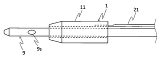
- FIG. 1 is a schematic cross-sectional view showing a first embodiment of a catheter.
- the catheter 1 is roughly composed of a hollow shaft 11 and a core wire 21.
- a metal braid 31 for reinforcing the hollow shaft 11 and a coating 41 covering the braid 31 are aligned on the inner peripheral surface of the resin layer on the tip side of the tip of the core wire 21. Is illustrated.
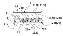
- the hollow shaft 11 is a hollow cylindrical member in which a plurality of resin layers including a first resin layer and a second resin layer are laminated. Specifically, for example, the hollow shaft 11 is provided on the inner circumference of the first resin layer 111 located at the outermost periphery and the first resin layer 111, and is inscribed in the first resin layer 111. It can be composed of two resin layers including the layer 112.
- the melt viscosity of the resin constituting the second resin layer 112 (hereinafter, also referred to as “second resin 112m”) is also referred to as the resin constituting the first resin layer 111 (hereinafter, also referred to as “first resin 111m”). ) Is configured to be smaller than the melt viscosity.
- the hardness of the resin constituting the first resin layer 111 is higher than the hardness of the resin constituting the second resin layer 112. As a result, the strength of the hollow shaft 11 is improved, the hollow shaft 11 is prevented from bending when the hollow shaft 11 is pushed by the core wire 21 (described later), and the pushability of the hollow shaft 11 can be further improved.
- the first and second resins 111m and 112m are related to the melt viscosity and hardness of the resin from, for example, polyamide, polyamide elastomer, polyolefin, polyester, polyester elastomer, polyurethane, silicone, fluororesin and the like, respectively. Can be selected to meet.
- the combination of the first and second resins 111m and 112m for example, two kinds of the above resins may be combined or the same kind of resin may be combined depending on the melt viscosity and hardness.
- the melt viscosity and hardness of the first and second resins can be adjusted by using resins of different grades.
- the core wire 21 is a member that is joined to the inner circumference of the hollow shaft 11 and has at least one through hole.
- the core wire 21 has, for example, a main body portion 21b having a substantially circular cross section and a thin plate-shaped tip portion 21t extending from the tip end of the main body portion 21b, and the tip portion 21t has a tip portion 21t. It can be configured to include a plurality of through holes 21h penetrating in the thickness direction (diameter direction of the hollow shaft 11).
- the core wire 21 can be arranged so that, for example, the main body portion 21b is located outside the base end side of the hollow shaft 11, and the tip end portion 21t is located in the middle of the hollow shaft 11 in the major axis direction. As shown in FIG.
- the tip portion 21t of the core wire 21 in the present embodiment is provided with two rows of through holes 21h along the long axis direction of the core wire 21.
- a handle (not shown) that can be gripped by the operator may be connected to the base end of the core wire 21.
- the material constituting the core wire 21 has a rigidity sufficient to securely push the hollow shaft 11 into the body cavity.
- the material constituting the core wire 21 include stainless steel such as SUS304, metal materials such as nickel titanium alloy and cobalt chromium alloy, and the like.
- second resin 112m a part of the above-mentioned second resin layer 112 (second resin 112m) is configured to penetrate into the through hole 21h. That is, the radial inner end 112a of the second resin layer 112 facing the through hole 21h is arranged so as to be closer to the central axis of the hollow shaft 11 than the radial outer end 21c of the through hole 21h. There is. It is preferable that a part of the second resin layer 112 penetrates into the inner wall 21w of the through hole 21h so as to adhere to the entire inner wall 21w of the through hole 21h. Is more preferable.
- the radial inner end 112a of the second resin layer 112 that has penetrated into the through hole 21h projects in the direction from the surface 21a of the core wire 21 (the surface closest to the central axis of the hollow shaft 11) toward the central axis. It is preferable that there is no such thing. Further, it is also preferable that the radial inner end portion 112a of the second resin layer 112 does not protrude from the surface 21a of the core wire 21 and has the same surface continuous with the surface 21a. Such a shape of the end portion 112a of the second resin layer 112 may allow the second resin layer 112 to penetrate into the through hole 21h, for example, with the end portion of the through hole 21h on the central axis side closed. , The second resin layer 112 can be obtained by invading the through hole 21h and then removing the protruding portion with a reamer or the like.
- a medical device for example, a guide wire or the like
- the medical device can be prevented from being caught in the through hole 21h.
- the opening area of the through hole 21h becomes smaller toward the inside in the radial direction of the hollow shaft 11.
- Examples of the shape of such a through hole 21h include a funnel shape and the like.
- the peripheral edge of the open end of the through hole 21h can be provided with a protruding portion 21p protruding toward the hollow shaft 11 side (diameterally outside of the hollow shaft 11).
- the protruding portion 21p bites into the hollow shaft 11 (for example, the second resin layer 112 or the like), so that the bonding strength between the hollow shaft 11 and the core wire 21 can be further increased.
- the protruding portion 21p can be formed in an annular shape over the entire peripheral edge of the open end of the through hole 21h, for example. As a result, the bonding strength between the hollow shaft 11 and the core wire 21 can be further increased by the amount that the protruding portion 21p bites into the hollow shaft 11.
- the catheter 1 can be manufactured, for example, by using a hollow shaft 11 and a core wire 21 molded into a predetermined shape and heat-bonding these members to each other.
- the heating temperature is preferably, for example, equal to or higher than the glass transition point from the viewpoint of improving the ease of penetration of the resin layers 111m and 112m into the through holes 21h.
- the pressure for crimping can be appropriately adjusted according to the state of penetration of the resin into the through hole 21h.
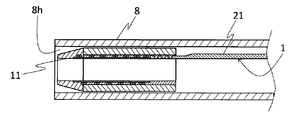
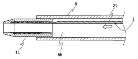
- the hollow shaft 11 of the catheter 1 is arranged in the lumen 8h of another catheter 8 (see FIG. 3A), and the core wire 21 is directed in the direction indicated by an arrow if necessary.
- the hollow shaft 11 is advanced from the tip of another catheter 8 by pushing it into the catheter 8 (see FIG. 3B), and the hollow shaft 11 is housed in the lumen 8h of the other catheter 8 by pulling the core wire 21.
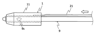
- the hollow shaft 11 is advanced by pushing the core wire 21 in the direction indicated by the arrow as necessary, and the opening 9s of the other medical device 9 is closed ( (See FIG. 4A), the hollow shaft 11 is retracted by pulling the core wire 21 to open the opening 9s of the other medical device 9 (see FIG. 4B).
- the catheter 1 can move the hollow shaft 11 back and forth in the body cavity by operating the core wire 21. Therefore, by using the catheter 1 in combination with another device (another catheter; another medical device such as a guide wire capture device, a stent delivery device, a balloon catheter, an endoscope), for example, of another catheter. It can be suitably used as an extension device whose tip can be substantially extended, and a coating device that covers the outer periphery of other medical devices in an openable and closable manner.
- another device another catheter; another medical device such as a guide wire capture device, a stent delivery device, a balloon catheter, an endoscope
- the catheter 1 since the catheter 1 has the above configuration, the second resin layer 112 can be easily and surely penetrated into the through hole 21h, and while maintaining good pushability in the body cavity, The bonding strength between the hollow shaft 11 and the core wire 21 can be improved.
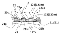
- FIG. 5 is a schematic cross-sectional view showing a part of the second embodiment in an enlarged manner.
- the catheter 2 is roughly composed of a hollow shaft 12 and a core wire 21.
- the catheter 2 differs from the first embodiment in that it includes a hollow shaft 12. Since the core wire 21 has the same configuration as that of the first embodiment, the same parts are designated by the same reference numerals and detailed description thereof will be omitted. Further, since the configurations other than the configurations shown below are the same as those of the first embodiment, the description thereof will be omitted.
- the hollow shaft 12 is a hollow cylindrical member in which a plurality of resin layers including a first resin layer and a second resin layer provided on the inner circumference of the first resin layer are laminated.
- the melt viscosity of the resin constituting the second resin layer is configured to be smaller than the melt viscosity of the resin constituting the first resin layer. Further, a part of the second resin layer has penetrated into the through hole.
- the protruding portion 21p bites into the second resin layer 122 of the catheter 2. Therefore, the bonding strength between the hollow shaft 12 and the core wire 21 can be further increased.
- the catheter 2 since the catheter 2 has the above configuration, the amount of the first resin 121m having a melt viscosity larger than the melt viscosity of the second resin 122m invading the through hole 21h is contained in the body cavity.
- the pushability of the hollow shaft 12 of the above can be improved.
- the catheter (2) comprises a hollow shaft containing a resin layer and a core wire joined to the inner circumference of the hollow shaft and having at least one through hole, the opening area of the through hole being radially inward of the hollow shaft. It is characterized in that the resin layer becomes smaller toward the inside and a part of the resin layer penetrates into the through hole.
- the third and fourth embodiments relating to the catheter (2) will be described.
- FIG. 6 is a schematic cross-sectional view showing a part of the third embodiment in an enlarged manner.
- the catheter 3 is roughly composed of a hollow shaft 13 and a core wire 21.
- the catheter 3 differs from the first embodiment in that it includes a hollow shaft 13. Since the core wire 21 has the same configuration as that of the first embodiment, the same parts are designated by the same reference numerals and detailed description thereof will be omitted. Further, since the configurations other than the configurations shown below are the same as those of the first embodiment, the description thereof will be omitted.
- the hollow shaft 13 is a hollow cylindrical member including a resin layer.
- the hollow shaft 13 can be composed of, for example, one resin layer 131 made of one kind of resin.
- Examples of the resin 131 m constituting the resin layer 131 include polyamide, polyamide elastomer, polyolefin, polyester, polyester elastomer, polyurethane, silicone, and fluororesin.
- a part of the resin layer 131 (resin 131 m) is configured to penetrate into the through hole 21h of the core wire 21. That is, the radial inner end 131a of the resin layer 131 facing the through hole 21h is arranged so as to be closer to the central axis of the hollow shaft 13 than the radial outer end 21c of the through hole 21h.
- the protruding portion 21p bites into the resin layer 131 of the catheter 3. Therefore, the bonding strength between the hollow shaft 13 and the core wire 21 can be further increased.
- a part of the resin layer 131 penetrates so as to adhere to the inner wall 21w of the through hole 21h, and more preferably to penetrate the entire inner wall 21w of the through hole 21h.
- the radial inner end 131a of the resin layer 131 that has penetrated into the through hole 21h does not project in the direction from the surface 21a of the core wire 21 (the surface closest to the central axis of the hollow shaft 13) toward the central axis.
- the radial inner end 131a of the resin layer 131 constitutes the same surface continuous with the surface 21a of the core wire 21.
- the opening area of the through hole 21h becomes smaller toward the inside in the radial direction of the hollow shaft 13, so that a part of the resin 131m constituting the resin layer 131 is formed. Can be easily and surely penetrated into the through hole 21h, and the bonding strength between the hollow shaft 13 and the core wire 21 can be increased.
- FIG. 7 is a schematic cross-sectional view showing a part of the fourth embodiment in an enlarged manner.
- the catheter 4 is roughly composed of a hollow shaft 14 and a core wire 21.
- the catheter 4 differs from the third embodiment in that it includes a hollow shaft 14. Since the core wire 21 has the same configuration as that of the third embodiment, the same parts are designated by the same reference numerals and detailed description thereof will be omitted. Further, since the configurations other than the configurations shown below are the same as those of the third embodiment, the description thereof will be omitted.
- the hollow shaft 14 is a hollow cylindrical member including a resin layer.
- the resin layer of the catheter 4 is composed of a plurality of resin layers including a first resin layer 141 and a second resin layer 142 provided on the inner circumference of the first resin layer 141.
- the melt viscosity of the resin 142 m constituting the resin layer 142 of 2 is configured to be higher than the melt viscosity of the resin 141 m constituting the first resin layer 141.
- the melt viscosities of the resins satisfy the above relationship, respectively. You can choose.
- the combination of the first and second resins 141m and 142m for example, two kinds of the above resins may be combined or the same kind of resin may be combined depending on the melt viscosity.
- the melt viscosities of the first and second resins 141 m and 142 m can be adjusted by using different grade resins.
- second resin layer 142 (second resin 142m) is configured to penetrate into the through hole 21h. That is, the radial inner end 142a of the second resin layer 142 facing the through hole 21h is arranged so as to be closer to the central axis of the hollow shaft 14 than the radial outer end 21c of the through hole 21h. There is.
- the protruding portion 21p bites into the second resin layer 142 of the catheter 4. Therefore, the bonding strength between the hollow shaft 14 and the core wire 21 can be further increased.
- the second resin 142m existing in the through hole 21h is the through hole 21h because the melt viscosity of the resin 142m is larger than the melt viscosity of the first resin 141m. It is difficult to pull out from the hollow shaft 14, and the bonding strength between the hollow shaft 14 and the core wire 21 can be improved.
- the catheters 1 and 2 provided with the core wire 21 in which the opening area of the through hole 21h becomes smaller in the radial direction of the hollow shafts 11 and 12 have been described.
- the opening area of the through hole 210h may be constant over the entire thickness direction of the core wire 210 (see the catheter 101 in FIG. 8A).
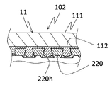
- the opening area of the through hole 220h may increase toward the inside in the radial direction of the hollow shaft 11 in the thickness direction of the core wire 220 (see the catheter 102 in FIG. 8B).
- the catheter provided with the braided body 31 and the coating 41 has been described.
- the catheter may not have the braided body 31 and the coating 41.
Landscapes
- Health & Medical Sciences (AREA)
- Life Sciences & Earth Sciences (AREA)
- Biophysics (AREA)
- Pulmonology (AREA)
- Engineering & Computer Science (AREA)
- Anesthesiology (AREA)
- Biomedical Technology (AREA)
- Heart & Thoracic Surgery (AREA)
- Hematology (AREA)
- Animal Behavior & Ethology (AREA)
- General Health & Medical Sciences (AREA)
- Public Health (AREA)
- Veterinary Medicine (AREA)
- Media Introduction/Drainage Providing Device (AREA)
Applications Claiming Priority (2)
| Application Number | Priority Date | Filing Date | Title |
|---|---|---|---|
| JP2020000557A JP2021108750A (ja) | 2020-01-06 | 2020-01-06 | カテーテル |
| JP2020-000557 | 2020-01-06 |
Publications (1)
| Publication Number | Publication Date |
|---|---|
| WO2021140883A1 true WO2021140883A1 (ja) | 2021-07-15 |
Family
ID=76787466
Family Applications (1)
| Application Number | Title | Priority Date | Filing Date |
|---|---|---|---|
| PCT/JP2020/047517 Ceased WO2021140883A1 (ja) | 2020-01-06 | 2020-12-18 | カテーテル |
Country Status (2)
| Country | Link |
|---|---|
| JP (1) | JP2021108750A (https=) |
| WO (1) | WO2021140883A1 (https=) |
Families Citing this family (1)
| Publication number | Priority date | Publication date | Assignee | Title |
|---|---|---|---|---|
| WO2025187635A1 (ja) * | 2024-03-04 | 2025-09-12 | 株式会社カネカ | 延長カテーテル |
Citations (2)
| Publication number | Priority date | Publication date | Assignee | Title |
|---|---|---|---|---|
| JP2001178826A (ja) * | 1999-12-27 | 2001-07-03 | Hirakawa Hewtech Corp | カテーテル用チューブ |
| JP2012510329A (ja) * | 2008-12-03 | 2012-05-10 | アンジオメト・ゲーエムベーハー・ウント・コンパニー・メディツィンテクニク・カーゲー | 伸縮自在なカテーテル |
Family Cites Families (1)
| Publication number | Priority date | Publication date | Assignee | Title |
|---|---|---|---|---|
| JP5818530B2 (ja) * | 2011-06-22 | 2015-11-18 | 株式会社グッドマン | カテーテル |
-
2020
- 2020-01-06 JP JP2020000557A patent/JP2021108750A/ja active Pending
- 2020-12-18 WO PCT/JP2020/047517 patent/WO2021140883A1/ja not_active Ceased
Patent Citations (2)
| Publication number | Priority date | Publication date | Assignee | Title |
|---|---|---|---|---|
| JP2001178826A (ja) * | 1999-12-27 | 2001-07-03 | Hirakawa Hewtech Corp | カテーテル用チューブ |
| JP2012510329A (ja) * | 2008-12-03 | 2012-05-10 | アンジオメト・ゲーエムベーハー・ウント・コンパニー・メディツィンテクニク・カーゲー | 伸縮自在なカテーテル |
Also Published As
| Publication number | Publication date |
|---|---|
| JP2021108750A (ja) | 2021-08-02 |
Similar Documents
| Publication | Publication Date | Title |
|---|---|---|
| US10695531B2 (en) | Balloon catheter and medical elongated body | |
| JP5696659B2 (ja) | カテーテルの製造方法 | |
| US6210396B1 (en) | Guiding catheter with tungsten loaded band | |
| EP2015821B1 (en) | Removable valves and methods for making them | |
| JP6248630B2 (ja) | バルーンカテーテルとその製造方法 | |
| EP2928380B1 (en) | Reinforced catheter transition with flexible tip portion | |
| CN110650767A (zh) | 导管 | |
| JP6592892B2 (ja) | バルーンカテーテル | |
| JP2013198633A (ja) | 医療機器および医療機器の製造方法 | |
| JPWO2008032412A1 (ja) | マイクロカテーテル | |
| JPH10511871A (ja) | 軟質チップ形成方法 | |
| CN102671278B (zh) | 具有阀的导管 | |
| CN102264428A (zh) | 导管 | |
| WO2013118649A1 (ja) | ガイドワイヤ | |
| JP2001178826A (ja) | カテーテル用チューブ | |
| WO2021140883A1 (ja) | カテーテル | |
| WO2018181962A1 (ja) | カテーテル用先端チップおよびステントデリバリー装置 | |
| JP2012045043A (ja) | 医療用器具 | |
| JPH05192389A (ja) | 生体内留置チューブ | |
| JP6713418B2 (ja) | カテーテル | |
| JP2018000372A (ja) | バルーンカテーテル | |
| JPWO2012057313A1 (ja) | 医療用ステントおよび医療用ステントの製造方法 | |
| JP2019024919A (ja) | カテーテル | |
| JP6319390B2 (ja) | 医療機器および医療機器の製造方法 | |
| CN112805055B (zh) | 医疗用的多腔管、以及医疗用的多腔管的制造方法 |
Legal Events
| Date | Code | Title | Description |
|---|---|---|---|
| 121 | Ep: the epo has been informed by wipo that ep was designated in this application |
Ref document number: 20912721 Country of ref document: EP Kind code of ref document: A1 |
|
| NENP | Non-entry into the national phase |
Ref country code: DE |
|
| 122 | Ep: pct application non-entry in european phase |
Ref document number: 20912721 Country of ref document: EP Kind code of ref document: A1 |