EP2928380B1 - Reinforced catheter transition with flexible tip portion - Google Patents
Reinforced catheter transition with flexible tip portion Download PDFInfo
- Publication number
- EP2928380B1 EP2928380B1 EP13861256.9A EP13861256A EP2928380B1 EP 2928380 B1 EP2928380 B1 EP 2928380B1 EP 13861256 A EP13861256 A EP 13861256A EP 2928380 B1 EP2928380 B1 EP 2928380B1
- Authority
- EP
- European Patent Office
- Prior art keywords
- sheath
- lumen
- distal
- guide wire
- distal tip
- Prior art date
- Legal status (The legal status is an assumption and is not a legal conclusion. Google has not performed a legal analysis and makes no representation as to the accuracy of the status listed.)
- Active
Links
- 230000007704 transition Effects 0.000 title claims description 22
- 239000000523 sample Substances 0.000 claims description 31
- 238000002604 ultrasonography Methods 0.000 claims description 30
- 229920000642 polymer Polymers 0.000 claims description 11
- 210000005166 vasculature Anatomy 0.000 claims description 7
- 229920005570 flexible polymer Polymers 0.000 claims description 5
- FAPWRFPIFSIZLT-UHFFFAOYSA-M Sodium chloride Chemical compound [Na+].[Cl-] FAPWRFPIFSIZLT-UHFFFAOYSA-M 0.000 claims description 4
- 238000003780 insertion Methods 0.000 claims description 4
- 230000037431 insertion Effects 0.000 claims description 4
- 239000011780 sodium chloride Substances 0.000 claims description 4
- 229920002614 Polyether block amide Polymers 0.000 claims description 3
- 239000011248 coating agent Substances 0.000 claims description 3
- 238000000576 coating method Methods 0.000 claims description 3
- 238000004891 communication Methods 0.000 claims description 3
- 239000004952 Polyamide Substances 0.000 claims description 2
- 229920001903 high density polyethylene Polymers 0.000 claims description 2
- 239000004700 high-density polyethylene Substances 0.000 claims description 2
- 229920001912 maleic anhydride grafted polyethylene Polymers 0.000 claims description 2
- 229920002647 polyamide Polymers 0.000 claims description 2
- 241001296096 Probles Species 0.000 claims 1
- 239000000463 material Substances 0.000 description 15
- 238000002608 intravascular ultrasound Methods 0.000 description 12
- 238000003384 imaging method Methods 0.000 description 11
- 208000012287 Prolapse Diseases 0.000 description 7
- 210000004204 blood vessel Anatomy 0.000 description 6
- 229920001169 thermoplastic Polymers 0.000 description 6
- 239000004416 thermosoftening plastic Substances 0.000 description 6
- 238000010276 construction Methods 0.000 description 5
- 239000012530 fluid Substances 0.000 description 5
- 238000005452 bending Methods 0.000 description 3
- 238000000034 method Methods 0.000 description 3
- 239000004642 Polyimide Substances 0.000 description 2
- 230000002411 adverse Effects 0.000 description 2
- 210000003484 anatomy Anatomy 0.000 description 2
- 238000002592 echocardiography Methods 0.000 description 2
- 238000010438 heat treatment Methods 0.000 description 2
- 229920001721 polyimide Polymers 0.000 description 2
- 229910001220 stainless steel Inorganic materials 0.000 description 2
- 239000010935 stainless steel Substances 0.000 description 2
- 239000004677 Nylon Substances 0.000 description 1
- 238000004026 adhesive bonding Methods 0.000 description 1
- 210000001367 artery Anatomy 0.000 description 1
- 230000005540 biological transmission Effects 0.000 description 1
- 210000004369 blood Anatomy 0.000 description 1
- 239000008280 blood Substances 0.000 description 1
- 238000001816 cooling Methods 0.000 description 1
- 238000002059 diagnostic imaging Methods 0.000 description 1
- 210000003743 erythrocyte Anatomy 0.000 description 1
- 230000002262 irrigation Effects 0.000 description 1
- 238000003973 irrigation Methods 0.000 description 1
- 239000000314 lubricant Substances 0.000 description 1
- 239000000155 melt Substances 0.000 description 1
- 229920001778 nylon Polymers 0.000 description 1
- 230000002093 peripheral effect Effects 0.000 description 1
- 230000001737 promoting effect Effects 0.000 description 1
- 238000009987 spinning Methods 0.000 description 1
- CCEKAJIANROZEO-UHFFFAOYSA-N sulfluramid Chemical group CCNS(=O)(=O)C(F)(F)C(F)(F)C(F)(F)C(F)(F)C(F)(F)C(F)(F)C(F)(F)C(F)(F)F CCEKAJIANROZEO-UHFFFAOYSA-N 0.000 description 1
- 230000002792 vascular Effects 0.000 description 1
Images
Classifications
-
- A—HUMAN NECESSITIES
- A61—MEDICAL OR VETERINARY SCIENCE; HYGIENE
- A61B—DIAGNOSIS; SURGERY; IDENTIFICATION
- A61B8/00—Diagnosis using ultrasonic, sonic or infrasonic waves
- A61B8/12—Diagnosis using ultrasonic, sonic or infrasonic waves in body cavities or body tracts, e.g. by using catheters
-
- B—PERFORMING OPERATIONS; TRANSPORTING
- B29—WORKING OF PLASTICS; WORKING OF SUBSTANCES IN A PLASTIC STATE IN GENERAL
- B29C—SHAPING OR JOINING OF PLASTICS; SHAPING OF MATERIAL IN A PLASTIC STATE, NOT OTHERWISE PROVIDED FOR; AFTER-TREATMENT OF THE SHAPED PRODUCTS, e.g. REPAIRING
- B29C65/00—Joining or sealing of preformed parts, e.g. welding of plastics materials; Apparatus therefor
- B29C65/02—Joining or sealing of preformed parts, e.g. welding of plastics materials; Apparatus therefor by heating, with or without pressure
-
- A—HUMAN NECESSITIES
- A61—MEDICAL OR VETERINARY SCIENCE; HYGIENE
- A61B—DIAGNOSIS; SURGERY; IDENTIFICATION
- A61B8/00—Diagnosis using ultrasonic, sonic or infrasonic waves
- A61B8/08—Detecting organic movements or changes, e.g. tumours, cysts, swellings
- A61B8/0891—Detecting organic movements or changes, e.g. tumours, cysts, swellings for diagnosis of blood vessels
-
- A—HUMAN NECESSITIES
- A61—MEDICAL OR VETERINARY SCIENCE; HYGIENE
- A61B—DIAGNOSIS; SURGERY; IDENTIFICATION
- A61B8/00—Diagnosis using ultrasonic, sonic or infrasonic waves
- A61B8/44—Constructional features of the ultrasonic, sonic or infrasonic diagnostic device
- A61B8/4444—Constructional features of the ultrasonic, sonic or infrasonic diagnostic device related to the probe
- A61B8/445—Details of catheter construction
-
- A—HUMAN NECESSITIES
- A61—MEDICAL OR VETERINARY SCIENCE; HYGIENE
- A61L—METHODS OR APPARATUS FOR STERILISING MATERIALS OR OBJECTS IN GENERAL; DISINFECTION, STERILISATION OR DEODORISATION OF AIR; CHEMICAL ASPECTS OF BANDAGES, DRESSINGS, ABSORBENT PADS OR SURGICAL ARTICLES; MATERIALS FOR BANDAGES, DRESSINGS, ABSORBENT PADS OR SURGICAL ARTICLES
- A61L29/00—Materials for catheters, medical tubing, cannulae, or endoscopes or for coating catheters
- A61L29/04—Macromolecular materials
- A61L29/041—Macromolecular materials obtained by reactions only involving carbon-to-carbon unsaturated bonds
-
- A—HUMAN NECESSITIES
- A61—MEDICAL OR VETERINARY SCIENCE; HYGIENE
- A61L—METHODS OR APPARATUS FOR STERILISING MATERIALS OR OBJECTS IN GENERAL; DISINFECTION, STERILISATION OR DEODORISATION OF AIR; CHEMICAL ASPECTS OF BANDAGES, DRESSINGS, ABSORBENT PADS OR SURGICAL ARTICLES; MATERIALS FOR BANDAGES, DRESSINGS, ABSORBENT PADS OR SURGICAL ARTICLES
- A61L29/00—Materials for catheters, medical tubing, cannulae, or endoscopes or for coating catheters
- A61L29/08—Materials for coatings
- A61L29/085—Macromolecular materials
-
- A—HUMAN NECESSITIES
- A61—MEDICAL OR VETERINARY SCIENCE; HYGIENE
- A61M—DEVICES FOR INTRODUCING MEDIA INTO, OR ONTO, THE BODY; DEVICES FOR TRANSDUCING BODY MEDIA OR FOR TAKING MEDIA FROM THE BODY; DEVICES FOR PRODUCING OR ENDING SLEEP OR STUPOR
- A61M25/00—Catheters; Hollow probes
- A61M25/0009—Making of catheters or other medical or surgical tubes
-
- B—PERFORMING OPERATIONS; TRANSPORTING
- B29—WORKING OF PLASTICS; WORKING OF SUBSTANCES IN A PLASTIC STATE IN GENERAL
- B29C—SHAPING OR JOINING OF PLASTICS; SHAPING OF MATERIAL IN A PLASTIC STATE, NOT OTHERWISE PROVIDED FOR; AFTER-TREATMENT OF THE SHAPED PRODUCTS, e.g. REPAIRING
- B29C65/00—Joining or sealing of preformed parts, e.g. welding of plastics materials; Apparatus therefor
- B29C65/66—Joining or sealing of preformed parts, e.g. welding of plastics materials; Apparatus therefor by liberation of internal stresses, e.g. shrinking of one of the parts to be joined
- B29C65/68—Joining or sealing of preformed parts, e.g. welding of plastics materials; Apparatus therefor by liberation of internal stresses, e.g. shrinking of one of the parts to be joined using auxiliary shrinkable elements
-
- B—PERFORMING OPERATIONS; TRANSPORTING
- B29—WORKING OF PLASTICS; WORKING OF SUBSTANCES IN A PLASTIC STATE IN GENERAL
- B29C—SHAPING OR JOINING OF PLASTICS; SHAPING OF MATERIAL IN A PLASTIC STATE, NOT OTHERWISE PROVIDED FOR; AFTER-TREATMENT OF THE SHAPED PRODUCTS, e.g. REPAIRING
- B29C66/00—General aspects of processes or apparatus for joining preformed parts
- B29C66/01—General aspects dealing with the joint area or with the area to be joined
- B29C66/05—Particular design of joint configurations
- B29C66/10—Particular design of joint configurations particular design of the joint cross-sections
- B29C66/11—Joint cross-sections comprising a single joint-segment, i.e. one of the parts to be joined comprising a single joint-segment in the joint cross-section
- B29C66/112—Single lapped joints
- B29C66/1122—Single lap to lap joints, i.e. overlap joints
-
- B—PERFORMING OPERATIONS; TRANSPORTING
- B29—WORKING OF PLASTICS; WORKING OF SUBSTANCES IN A PLASTIC STATE IN GENERAL
- B29C—SHAPING OR JOINING OF PLASTICS; SHAPING OF MATERIAL IN A PLASTIC STATE, NOT OTHERWISE PROVIDED FOR; AFTER-TREATMENT OF THE SHAPED PRODUCTS, e.g. REPAIRING
- B29C66/00—General aspects of processes or apparatus for joining preformed parts
- B29C66/50—General aspects of joining tubular articles; General aspects of joining long products, i.e. bars or profiled elements; General aspects of joining single elements to tubular articles, hollow articles or bars; General aspects of joining several hollow-preforms to form hollow or tubular articles
- B29C66/51—Joining tubular articles, profiled elements or bars; Joining single elements to tubular articles, hollow articles or bars; Joining several hollow-preforms to form hollow or tubular articles
- B29C66/52—Joining tubular articles, bars or profiled elements
- B29C66/522—Joining tubular articles
- B29C66/5221—Joining tubular articles for forming coaxial connections, i.e. the tubular articles to be joined forming a zero angle relative to each other
-
- B—PERFORMING OPERATIONS; TRANSPORTING
- B29—WORKING OF PLASTICS; WORKING OF SUBSTANCES IN A PLASTIC STATE IN GENERAL
- B29C—SHAPING OR JOINING OF PLASTICS; SHAPING OF MATERIAL IN A PLASTIC STATE, NOT OTHERWISE PROVIDED FOR; AFTER-TREATMENT OF THE SHAPED PRODUCTS, e.g. REPAIRING
- B29C66/00—General aspects of processes or apparatus for joining preformed parts
- B29C66/50—General aspects of joining tubular articles; General aspects of joining long products, i.e. bars or profiled elements; General aspects of joining single elements to tubular articles, hollow articles or bars; General aspects of joining several hollow-preforms to form hollow or tubular articles
- B29C66/51—Joining tubular articles, profiled elements or bars; Joining single elements to tubular articles, hollow articles or bars; Joining several hollow-preforms to form hollow or tubular articles
- B29C66/52—Joining tubular articles, bars or profiled elements
- B29C66/522—Joining tubular articles
- B29C66/5229—Joining tubular articles involving the use of a socket
- B29C66/52291—Joining tubular articles involving the use of a socket said socket comprising a stop
- B29C66/52292—Joining tubular articles involving the use of a socket said socket comprising a stop said stop being internal
-
- B—PERFORMING OPERATIONS; TRANSPORTING
- B29—WORKING OF PLASTICS; WORKING OF SUBSTANCES IN A PLASTIC STATE IN GENERAL
- B29C—SHAPING OR JOINING OF PLASTICS; SHAPING OF MATERIAL IN A PLASTIC STATE, NOT OTHERWISE PROVIDED FOR; AFTER-TREATMENT OF THE SHAPED PRODUCTS, e.g. REPAIRING
- B29C66/00—General aspects of processes or apparatus for joining preformed parts
- B29C66/50—General aspects of joining tubular articles; General aspects of joining long products, i.e. bars or profiled elements; General aspects of joining single elements to tubular articles, hollow articles or bars; General aspects of joining several hollow-preforms to form hollow or tubular articles
- B29C66/63—Internally supporting the article during joining
-
- B—PERFORMING OPERATIONS; TRANSPORTING
- B29—WORKING OF PLASTICS; WORKING OF SUBSTANCES IN A PLASTIC STATE IN GENERAL
- B29C—SHAPING OR JOINING OF PLASTICS; SHAPING OF MATERIAL IN A PLASTIC STATE, NOT OTHERWISE PROVIDED FOR; AFTER-TREATMENT OF THE SHAPED PRODUCTS, e.g. REPAIRING
- B29C66/00—General aspects of processes or apparatus for joining preformed parts
- B29C66/70—General aspects of processes or apparatus for joining preformed parts characterised by the composition, physical properties or the structure of the material of the parts to be joined; Joining with non-plastics material
- B29C66/72—General aspects of processes or apparatus for joining preformed parts characterised by the composition, physical properties or the structure of the material of the parts to be joined; Joining with non-plastics material characterised by the structure of the material of the parts to be joined
- B29C66/723—General aspects of processes or apparatus for joining preformed parts characterised by the composition, physical properties or the structure of the material of the parts to be joined; Joining with non-plastics material characterised by the structure of the material of the parts to be joined being multi-layered
-
- B—PERFORMING OPERATIONS; TRANSPORTING
- B29—WORKING OF PLASTICS; WORKING OF SUBSTANCES IN A PLASTIC STATE IN GENERAL
- B29C—SHAPING OR JOINING OF PLASTICS; SHAPING OF MATERIAL IN A PLASTIC STATE, NOT OTHERWISE PROVIDED FOR; AFTER-TREATMENT OF THE SHAPED PRODUCTS, e.g. REPAIRING
- B29C66/00—General aspects of processes or apparatus for joining preformed parts
- B29C66/80—General aspects of machine operations or constructions and parts thereof
- B29C66/82—Pressure application arrangements, e.g. transmission or actuating mechanisms for joining tools or clamps
- B29C66/828—Other pressure application arrangements
-
- A—HUMAN NECESSITIES
- A61—MEDICAL OR VETERINARY SCIENCE; HYGIENE
- A61L—METHODS OR APPARATUS FOR STERILISING MATERIALS OR OBJECTS IN GENERAL; DISINFECTION, STERILISATION OR DEODORISATION OF AIR; CHEMICAL ASPECTS OF BANDAGES, DRESSINGS, ABSORBENT PADS OR SURGICAL ARTICLES; MATERIALS FOR BANDAGES, DRESSINGS, ABSORBENT PADS OR SURGICAL ARTICLES
- A61L2400/00—Materials characterised by their function or physical properties
- A61L2400/10—Materials for lubricating medical devices
-
- A—HUMAN NECESSITIES
- A61—MEDICAL OR VETERINARY SCIENCE; HYGIENE
- A61L—METHODS OR APPARATUS FOR STERILISING MATERIALS OR OBJECTS IN GENERAL; DISINFECTION, STERILISATION OR DEODORISATION OF AIR; CHEMICAL ASPECTS OF BANDAGES, DRESSINGS, ABSORBENT PADS OR SURGICAL ARTICLES; MATERIALS FOR BANDAGES, DRESSINGS, ABSORBENT PADS OR SURGICAL ARTICLES
- A61L2420/00—Materials or methods for coatings medical devices
- A61L2420/08—Coatings comprising two or more layers
-
- B—PERFORMING OPERATIONS; TRANSPORTING
- B29—WORKING OF PLASTICS; WORKING OF SUBSTANCES IN A PLASTIC STATE IN GENERAL
- B29C—SHAPING OR JOINING OF PLASTICS; SHAPING OF MATERIAL IN A PLASTIC STATE, NOT OTHERWISE PROVIDED FOR; AFTER-TREATMENT OF THE SHAPED PRODUCTS, e.g. REPAIRING
- B29C66/00—General aspects of processes or apparatus for joining preformed parts
- B29C66/70—General aspects of processes or apparatus for joining preformed parts characterised by the composition, physical properties or the structure of the material of the parts to be joined; Joining with non-plastics material
- B29C66/71—General aspects of processes or apparatus for joining preformed parts characterised by the composition, physical properties or the structure of the material of the parts to be joined; Joining with non-plastics material characterised by the composition of the plastics material of the parts to be joined
-
- B—PERFORMING OPERATIONS; TRANSPORTING
- B29—WORKING OF PLASTICS; WORKING OF SUBSTANCES IN A PLASTIC STATE IN GENERAL
- B29L—INDEXING SCHEME ASSOCIATED WITH SUBCLASS B29C, RELATING TO PARTICULAR ARTICLES
- B29L2031/00—Other particular articles
- B29L2031/753—Medical equipment; Accessories therefor
- B29L2031/7542—Catheters
Definitions
- the present disclosure relates generally to catheters for navigating through the human vasculature, and in particular, to improved catheter tip designs and reinforced sections of the catheter.
- Intravascular ultrasound (IVUS) imaging is widely used in interventional cardiology as a diagnostic tool for assessing a vessel, such as an artery, within the human body to determine the need for treatment, to guide intervention, and/or to assess its effectiveness.
- An IVUS imaging system uses ultrasound echoes to form a cross-sectional image of the vessel of interest.
- IVUS imaging uses a transducer carried by an IVUS catheter that both emits ultrasound signals (waves) and receives the reflected ultrasound signals.
- the emitted ultrasound signals (often referred to as ultrasound pulses) pass easily through most tissues and blood, but they are partially reflected by discontinuities arising from tissue structures (such as the various layers of the vessel wall), red blood cells, and other features of interest.
- the IVUS imaging system which is connected to the IVUS catheter by way of a patient interface module, processes the received ultrasound signals (often referred to as ultrasound echoes) to produce a cross-sectional image of the vessel where the IVUS catheter is located.
- US 2005/131445 A1 discloses distal tip designs for catheter, wherein distal tip material is positioned about an inner shaft and which is used as a tie layer for thermally bonding two incompatible materials together, such as a waist portion of a balloon to the inner shaft.
- US 2008/262470 A1 discloses a balloon catheter having a soft distal tip member having a non-tacky inner layer material and a soft flexible outer layer material, with both materials being readily thermally bondable to the catheter balloon.
- US 2011/208164 A1 discloses a device having a first sheath with a proximal end portion and a distal end portion defining a passageway therebetween, wherein the distal end portion has melt bonding material.
- a second sheath has a first end portion and a second end portion defining a channel therebetween, wherein the second end portion has melt bonding material.
- An outer sleeve body comprising melt-bonding material operatively couples to the first sheath distal end portion and to the second sheath second end portion.
- Short guide wire lumen rapid exchange (RX) catheter designs or “monorail” designs generally employ a much shorter guide wire lumen at the distal end of the catheter, typically in the range from about 1 cm to 4 cm.
- the transducer may then be disposed axially spaced but close to the guide wire lumen, allowing a reduction in the total cross-sectional area of the catheter.
- the distal end or tip of the catheter may kink as it is advanced through the patient's vasculature. The unwanted bending may occur in the region of a guide wire side port, irrigation port, or any unsupported region distal region of the imaging system sheath.
- Kinking is the result of a deformation of the distal tip and usually is characterized by a sharp deformation or point bend of the very distal section of the catheter. Such a deformation may result from attempting to pass the distal tip through a very tortuous vascular section. Parts of the catheter may also kink or bend back upon itself in a condition referred to as prolapse. Thereafter, the catheter may return to its original shape, or it may remain permanently deformed if, during the bending, catheter material is bent beyond its elastic limit.
- the transition between the proximal section and the distal section of the catheter should also provide a good transition in flexibility from the relatively stiff proximal section to the relatively flexible distal section to facilitate tracking the catheter within the patient's tortuous vasculature.
- One difficulty has been that catheter junctions often result in a lump, step, or other surface irregularity in the bond junction.
- a sheath for an intravascular probe for insertion into a vasculature in accordance with claim 1.
- the present disclosure provides improved structural arrangements for the distal portion of intravascular devices, including intravascular imaging devices.
- the constructions of the present disclosure result in intravascular devices having improved handling characteristics due to the combination of flexibility and resistance to kinking or prolapse when introduced through tortuous regions of blood vessels.
- An exemplary tip construction includes three layers.
- the first layer is an inner layer adjacent to a guide wire lumen
- the second layer is a middle layer adjacent the inner layer
- the third layer is an outer layer adjacent the middle layer.
- the first layer typically includes a lubricious polymer to promote low friction and ease of tracking over the guide wire.
- the second layer generally includes a polymer that adheres well to both the inner and outer layers.
- the third layer usually includes a polymer that is flexible and that can also be coated with a hydrophilic coating. This construction provides low friction and good guide wire movement, along with reduced friction between the catheter and blood vessel wall.
- the sheath includes a flexible portion having a lumen for receiving an ultrasound probe and a distal portion that includes a flexible tip.
- the tip defines a guide wire lumen having a distal guide wire opening and a proximal guide wire opening through a sidewalk.
- An area between the proximal guide wire entry opening and the flexible proximal portion is supported to prevent prolapse.
- the area is supported by a tube, which may comprise a polyimide and/or stainless steel.
- the tube includes an inner lumen in communication with the ultrasound lumen and a flush hole through the tube.
- the sheath provides a flexible device that is locally reinforced between the proximal guide wire entry opening and ultrasound probe so that the monorail is flexible, tracks well, and does not prolapse. The additional support prevents localized kinking.
- a rotational intravascular probe or catheter 100 for insertion into a patient for diagnostic imaging is shown.
- the IVUS probe 100 is similar to a Revolution® Rotational IVUS Imaging Catheter available from Volcano Corporation and/or rotational IVUS catheters disclosed in U.S. Patent No. 5,243,988 and U.S. Patent No. 5,546,948 .
- the probe 100 includes an elongated, flexible catheter sheath having a flexible proximal portion 130, a distal portion 110 shaped and configured for insertion into a lumen of a blood vessel, and a transition portion 120 that couples the proximal portion and the distal portion.
- the probe 100 is flexible such that it can adapt to the curvature of the blood vessel during use.
- the probe 100 may be configured to take on any desired straight or arcuate profile when in use.
- the probe 100 comprises a sheath and a transducer shaft surrounded by the sheath.
- the transducer shaft is flushed with a sterile fluid, such as saline, within the catheter body.
- a sterile fluid such as saline
- the fluid serves to eliminate the presence of air pockets or bubbles around the transducer shaft that adversely affect image quality.
- the fluid can also act as a lubricant.
- the distal portion 110 of the sheath is inserted into a patient during the operation of the probe 100.
- the distal portion 110 includes a short tip. With short tips, only the very distal end of the catheter follows the guide wire, while the remainder of the catheter is left to move as needed within a blood vessel.
- the short tip in illustrated embodiment is about 22-23 mm compared to about 22 cm for most other long tipped coronary RX catheters. In one embodiment, the tip is 23 mm.
- the transition portion 120 of the sheath is typically only about 1-3 mm, but is typically not supported by a guide wire like the tip, or by the transducer shaft like the proximal portion 130.
- the transition portion 120 is only about 3 mm in length and has a diameter of about 1.07 mm (3.2 French (F)) or about 1 mm.
- F French
- the proximal portion 130 of the sheath and the proximal end portion of the transducer shaft are connected to an interface module.
- the rotation of the transducer shaft within the catheter body is controlled by the interface module, which provides a plurality of user interface controls that can be manipulated by a user.
- the interface module can receive, analyze, and/or display information received through the transducer shaft.
- the usable length of the probe 100 can be any suitable length and can be varied depending upon the application.
- the overall dimensions of the catheter will depend on use, with the length varying widely, typically being between about 40 cm and 150 cm, usually being between about 40 cm and 120 cm for peripheral catheters and being between about 110 cm and 150 cm for coronary catheters.
- the diameter of the catheter body may also vary widely, with the diameter of the distal portion 110 typically being between about 0.67 mm (2F) and 1.33 mm (4F), and the diameter of the proximal portion 130 typically being about 1 mm (3F) and 2 mm (6F). In an exemplary embodiment, the diameter of the proximal portion 130 is 1.17 mm (3.5 F).
- FIG. 2 is a top view
- FIG. 3 is cross-sectional side view taken along line 3-3 of FIG. 2 .
- the sheath 200 is axially compressed.
- the sheath 200 employs a RX design, whereby a guide wire 255 enters the sheath 200 less than about 0.3 cm from the distal end or tip to allow an ultrasound probe 270 to be placed as close to the tip as possible.
- the sheath 200 may be placed on guide wire 255 by threading the guide wire 255 through the distal guide wire opening 240, then the guide wire lumen 218, and finally the proximal guide wire opening 250.
- the proximal guide wire exit opening 250 extends through a sidewall of the sheath 200. The catheter body can then be then advanced along the guide wire 255 until the sheath 200 lies within the region of interest.
- proximal guide wire exit opening 250 includes a flush hole 252 to allow saline to flow out of the ultrasound probe lumen 235 in the direction of arrow F.
- a separate flush hole (not shown) is formed through support tube 260 and outer tube 290 opposite the guide wire exit opening.
- the ultrasound probe lumen 235 may extend from the proximal end of the sheath 200 to the distal tip thereof, but will usually be terminated before reaching the distal tip.
- the guide wire lumen 218 may be disposed at least partially adjacent to the ultrasound probe lumen 235.
- the distal tip portion 210 is coupled to the transition portion 220 and the proximal portion 230 by adhesive bonding 254.
- transition portion 220 and proximal portion 230 include the outer tube 290 that defines the ultrasound probe lumen 235.
- support tube 260 Within the transition portion 220 is support tube 260 to help support the transition portion 220 during use.
- the support tube 260 provides stiffness and controlled bending of the sheath 200 in the region proximal the proximal guide wire exit opening 250 and distal the ultrasound probe 270.
- the ultrasound probe 270 extends within the ultrasound probe lumen but does not extend into the support tube 260.
- the ultrasound probe 270 is located at an end of a flexible transducer drive shaft that spins inside the sheath 200 inserted into the vessel of interest.
- the ultrasound probe 270 is usually oriented such that the ultrasound signals propagate generally perpendicular to an axis of the catheter.
- the fluid-filled (e.g., saline-filled) sheath 290 protects the vessel tissue from the spinning probe and shaft while permitting ultrasound signals to freely propagate from the probe into the tissue and back.
- the probe As the shaft rotates (for example, at 30 revolutions per second), the probe is periodically excited with a high voltage pulse to emit a short burst of ultrasound.
- the ultrasound signals are emitted from the probe, through the fluid-filled sheath and sheath wall, in a direction generally perpendicular to an axis of rotation of the shaft.
- the same probe then listens for returning ultrasound signals reflected from various tissue structures, and the imaging system assembles a two dimensional image of the vessel cross-section from a sequence of several hundred of these ultrasound pulse/echo acquisition sequences occurring during a single revolution of the probe.
- the distal portion 210 includes a flexible distal tip having a multi-layer construction.
- the distal tip includes three layers: an inner layer 212 adjacent the guide wire lumen 218, a middle layer 214 adjacent the inner layer 212, and an outer layer 216 adjacent the middle layer 214. Flexibility is needed to make tortuous turns in the vasculature while following the guide wire 255, but rigidity is also needed to allow the tip to track along the guide wire.
- the length of the distal tip 210 is about 22 mm. In an alternative embodiment, the length of the tip is less than about 3 cm.
- the inner layer 212 includes a lubricious polymer that slides easily over guide wire 255.
- the lubricious polymer includes a high-density polyethylene to promote low friction and ease of tracking over the guide wire 255.
- the middle layer 214 includes a polymer that adheres to the inner layer 212 and the outer layer 216.
- the polymer includes a functionalized or maleic anhydride grafted polyethylene.
- the outer layer 216 includes a flexible polymer.
- the flexible polymer includes a polyether block amide and/or polyamide.
- the flexible polymer can make tight or tortuous bends in the anatomy.
- the outer layer 216 can be coated with a polymeric hydrophilic coating to reduce tracking friction against vessel walls in the anatomy.
- the transition portion 220 includes support tube 260.
- the support tube 260 is located in an area between the proximal guide wire opening 250 and the flexible proximal portion 230.
- the support tube 260 may be positioned within a distal extremity of the lumen 235.
- the support tube 260 is formed of any material suitable to reinforce the transition portion 220 so that the transition portion 220 is supported and does not prolapse.
- the support tube 260 includes polyimide and/or stainless steel.
- the support tube 260 includes an inner lumen in communication with the ultrasound probe lumen 235 and a flush hole 252 through at least a portion of the support tube 260.
- the support member 260 has a length between 1-3 mm. In a further aspect, the support member 260 has a length of approximately 2 mm.
- the sheath 200 of the present disclosure has excellent ability to track within the patient's tortuous vasculature due to the improved design of the distal tip portion 210 and the reinforced transition portion 220.
- the outer sheath 290 may be formed from a single tubular member that extends the entire distance from the proximal portion 130 to the distal portion 110 or may be formed from two or more tubular members that are joined together. The two tubular members may be joined together so that they share a common inner lumen. As shown in FIG. 1 at detail 5, the outer sheath 290 transitions from a distal diameter of 1.07 mm (3.2F) to a proximal diameter of 1.17 mm (3.5 F).
- the subassembly is formed by positioning one end of a first catheter shaft portion 310 into an end of a second catheter shaft portion 320.
- the first catheter shaft portion 310 has an outer diameter D1 of approximately 1.07 mm (3.2F) that is different than the outer diameter D2 of approximately 1.17 mm (3.5F) of the second catheter shaft portion 320.
- a mandrel 350 is positioned in the inner lumen to keep the inner lumen open during the fusing of the first catheter shaft portion 310 and second catheter shaft portion 320.
- a sleeve 330 is placed over a junction 315 of the two shaft portions 310, 320.
- the sleeve 330 includes the same material as one or both of the two shaft portions 310, 320.
- the sleeve 430 includes a nylon and/or polyether block amide.
- the sleeve includes a shoulder 332 separating a first portion 334 having a first diameter substantially matching D1 and a second portion 336 having a diameter substantially matching D2.
- a heat shrink thermoplastic sleeve 340 is placed over the sleeve 330 and the junction 315 to create final subassembly.
- Bonding of the subassembly is completed by applying heat to the subassembly melt the catheter portions and sleeve.
- the heat shrink thermoplastic sleeve 340 shrinks and constrains a flow of the sleeve material 330 and catheter materials at the junction 315.
- the sleeve material 330 melts and fuses the two shaft portions 310, 320 together.
- the sleeve material 330 flows and fills in around the junction 315 to form a transition zone 360.
- the heat shrink thermoplastic sleeve 340 is removed.
- the heat shrink thermoplastic sleeve 340 created a smooth and long transition zone 360 from the first shaft portion 310 to the second shaft portion 320 over the junction 315.
- the heat shrink thermoplastic sleeve 440 results in a stronger junction 415 compared to a method that does not use sleeve 440.
- the use of a thermoplastic sleeve helps to strengthen and improve the thermally bonded catheter junctions by filling in surface irregularities and providing a smooth transition from one shaft to the next over the entire length of the bond junction. This smooth transition presents an atraumatic surface to tissue as the sheath is advanced within the body.
Description
- The present disclosure relates generally to catheters for navigating through the human vasculature, and in particular, to improved catheter tip designs and reinforced sections of the catheter.
- Intravascular ultrasound (IVUS) imaging is widely used in interventional cardiology as a diagnostic tool for assessing a vessel, such as an artery, within the human body to determine the need for treatment, to guide intervention, and/or to assess its effectiveness. An IVUS imaging system uses ultrasound echoes to form a cross-sectional image of the vessel of interest. Typically, IVUS imaging uses a transducer carried by an IVUS catheter that both emits ultrasound signals (waves) and receives the reflected ultrasound signals. The emitted ultrasound signals (often referred to as ultrasound pulses) pass easily through most tissues and blood, but they are partially reflected by discontinuities arising from tissue structures (such as the various layers of the vessel wall), red blood cells, and other features of interest. The IVUS imaging system, which is connected to the IVUS catheter by way of a patient interface module, processes the received ultrasound signals (often referred to as ultrasound echoes) to produce a cross-sectional image of the vessel where the IVUS catheter is located.
-
US 2005/131445 A1 discloses distal tip designs for catheter, wherein distal tip material is positioned about an inner shaft and which is used as a tie layer for thermally bonding two incompatible materials together, such as a waist portion of a balloon to the inner shaft. -
US 2008/262470 A1 discloses a balloon catheter having a soft distal tip member having a non-tacky inner layer material and a soft flexible outer layer material, with both materials being readily thermally bondable to the catheter balloon. -
US 2011/208164 A1 discloses a device having a first sheath with a proximal end portion and a distal end portion defining a passageway therebetween, wherein the distal end portion has melt bonding material. A second sheath has a first end portion and a second end portion defining a channel therebetween, wherein the second end portion has melt bonding material. An outer sleeve body comprising melt-bonding material operatively couples to the first sheath distal end portion and to the second sheath second end portion. - Short guide wire lumen rapid exchange (RX) catheter designs or "monorail" designs generally employ a much shorter guide wire lumen at the distal end of the catheter, typically in the range from about 1 cm to 4 cm. The transducer may then be disposed axially spaced but close to the guide wire lumen, allowing a reduction in the total cross-sectional area of the catheter. Among the difficulties sometimes encountered with short tipped guide wire catheters is the possibility that the distal end or tip of the catheter may kink as it is advanced through the patient's vasculature. The unwanted bending may occur in the region of a guide wire side port, irrigation port, or any unsupported region distal region of the imaging system sheath. Kinking is the result of a deformation of the distal tip and usually is characterized by a sharp deformation or point bend of the very distal section of the catheter. Such a deformation may result from attempting to pass the distal tip through a very tortuous vascular section. Parts of the catheter may also kink or bend back upon itself in a condition referred to as prolapse. Thereafter, the catheter may return to its original shape, or it may remain permanently deformed if, during the bending, catheter material is bent beyond its elastic limit.
- Once the catheter has been kinked, the performance of the catheter is substantially degraded. Higher friction will be encountered at the location of the kink, adversely affecting torque transmission, as well as making it more difficult to advance the catheter over the guide wire.
- The transition between the proximal section and the distal section of the catheter should also provide a good transition in flexibility from the relatively stiff proximal section to the relatively flexible distal section to facilitate tracking the catheter within the patient's tortuous vasculature. One difficulty has been that catheter junctions often result in a lump, step, or other surface irregularity in the bond junction.
- Therefore, a need exists for catheters that are resistant to kinking or prolapse when introduced through tortuous regions of blood vessels.
- According to the present invention, there is provided a sheath for an intravascular probe for insertion into a vasculature, in accordance with claim 1.
- The present disclosure provides improved structural arrangements for the distal portion of intravascular devices, including intravascular imaging devices. In particular, the constructions of the present disclosure result in intravascular devices having improved handling characteristics due to the combination of flexibility and resistance to kinking or prolapse when introduced through tortuous regions of blood vessels.
- The present disclosure describes various examples of a distal tip construction for use in intravascular ultrasound (IVUS) imaging. An exemplary tip construction includes three layers. The first layer is an inner layer adjacent to a guide wire lumen, the second layer is a middle layer adjacent the inner layer, and the third layer is an outer layer adjacent the middle layer. The first layer typically includes a lubricious polymer to promote low friction and ease of tracking over the guide wire. The second layer generally includes a polymer that adheres well to both the inner and outer layers. The third layer usually includes a polymer that is flexible and that can also be coated with a hydrophilic coating. This construction provides low friction and good guide wire movement, along with reduced friction between the catheter and blood vessel wall.
- In other examples, the sheath includes a flexible portion having a lumen for receiving an ultrasound probe and a distal portion that includes a flexible tip. The tip defines a guide wire lumen having a distal guide wire opening and a proximal guide wire opening through a sidewalk. An area between the proximal guide wire entry opening and the flexible proximal portion is supported to prevent prolapse. In some examples, the area is supported by a tube, which may comprise a polyimide and/or stainless steel. In alternative examples, the tube includes an inner lumen in communication with the ultrasound lumen and a flush hole through the tube. The sheath provides a flexible device that is locally reinforced between the proximal guide wire entry opening and ultrasound probe so that the monorail is flexible, tracks well, and does not prolapse. The additional support prevents localized kinking.
- Both the foregoing general description and the following detailed description are exemplary and explanatory in nature and are intended to provide an understanding of the present disclosure without limiting the scope of the present disclosure. In that regard, additional aspects, features, and advantages of the present disclosure will become apparent to one skilled in the art from the following detailed description.
- Aspects of the present disclosure are best understood from the following detailed description when read with the accompanying figures. It is emphasized that, in accordance with the standard practice in the industry, various features are not drawn to scale. In fact, the dimensions of the various features may be arbitrarily increased or reduced for clarity of discussion. In addition, the present disclosure may repeat reference numerals and/or letters in the various examples. This repetition is for the purpose of simplicity and clarity and does not in itself dictate a relationship between the various embodiments and/or configurations discussed.
-
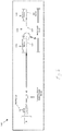
FIG. 1 is an illustration of an intravascular ultrasound (IVUS) imaging catheter according to various aspects of the present disclosure. -
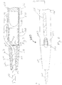
FIG. 2 is a stylized top view of a distal portion of a sheath for a rotational imaging system. -
FIG. 3 is a diagrammatic cross-sectional side view of the sheath ofFIG. 2 taken along line 3-3. -
FIG. 4 illustrates a subassembly of catheter shaft portions to be bonded according to various aspects of the present disclosure. -
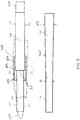
FIG. 5 illustrates a transition junction between sheath sections of different diameters. - For the purposes of promoting an understanding of the principles of the present disclosure, reference will now be made to the embodiments illustrated in the drawings, and specific language will be used to describe the same.
- Referring specifically to
FIG. 1 , a rotational intravascular probe orcatheter 100 for insertion into a patient for diagnostic imaging is shown. In some embodiments, the IVUSprobe 100 is similar to a Revolution® Rotational IVUS Imaging Catheter available from Volcano Corporation and/or rotational IVUS catheters disclosed inU.S. Patent No. 5,243,988 andU.S. Patent No. 5,546,948 . Theprobe 100 includes an elongated, flexible catheter sheath having a flexibleproximal portion 130, adistal portion 110 shaped and configured for insertion into a lumen of a blood vessel, and atransition portion 120 that couples the proximal portion and the distal portion. Theprobe 100 is flexible such that it can adapt to the curvature of the blood vessel during use. Generally, theprobe 100 may be configured to take on any desired straight or arcuate profile when in use. - The
probe 100 comprises a sheath and a transducer shaft surrounded by the sheath. The transducer shaft is flushed with a sterile fluid, such as saline, within the catheter body. The fluid serves to eliminate the presence of air pockets or bubbles around the transducer shaft that adversely affect image quality. The fluid can also act as a lubricant. - The
distal portion 110 of the sheath is inserted into a patient during the operation of theprobe 100. Thedistal portion 110 includes a short tip. With short tips, only the very distal end of the catheter follows the guide wire, while the remainder of the catheter is left to move as needed within a blood vessel. The short tip in illustrated embodiment is about 22-23 mm compared to about 22 cm for most other long tipped coronary RX catheters. In one embodiment, the tip is 23 mm. - The
transition portion 120 of the sheath is typically only about 1-3 mm, but is typically not supported by a guide wire like the tip, or by the transducer shaft like theproximal portion 130. In one embodiment, thetransition portion 120 is only about 3 mm in length and has a diameter of about 1.07 mm (3.2 French (F)) or about 1 mm. Thus, in prior designs this unsupported area is prone to kinking or prolapse. - The
proximal portion 130 of the sheath and the proximal end portion of the transducer shaft are connected to an interface module. The rotation of the transducer shaft within the catheter body is controlled by the interface module, which provides a plurality of user interface controls that can be manipulated by a user. The interface module can receive, analyze, and/or display information received through the transducer shaft. - The usable length of the probe 100 (the portion that can be inserted into a patient) can be any suitable length and can be varied depending upon the application. The overall dimensions of the catheter will depend on use, with the length varying widely, typically being between about 40 cm and 150 cm, usually being between about 40 cm and 120 cm for peripheral catheters and being between about 110 cm and 150 cm for coronary catheters. The diameter of the catheter body may also vary widely, with the diameter of the
distal portion 110 typically being between about 0.67 mm (2F) and 1.33 mm (4F), and the diameter of theproximal portion 130 typically being about 1 mm (3F) and 2 mm (6F). In an exemplary embodiment, the diameter of theproximal portion 130 is 1.17 mm (3.5 F). Turning now toFIGS. 2 and 3 , illustrated is a portion of asheath 200 showing a stylized portion of thedistal tip 210 and the reinforcedtransition region 220 according to the present disclosure.FIG. 2 is a top view, whileFIG. 3 is cross-sectional side view taken along line 3-3 ofFIG. 2 . For purposes of illustration, thesheath 200 is axially compressed. Thesheath 200 employs a RX design, whereby aguide wire 255 enters thesheath 200 less than about 0.3 cm from the distal end or tip to allow anultrasound probe 270 to be placed as close to the tip as possible. In use, thesheath 200 may be placed onguide wire 255 by threading theguide wire 255 through the distalguide wire opening 240, then theguide wire lumen 218, and finally the proximalguide wire opening 250. As shown inFIGS. 2 and 3 , the proximal guidewire exit opening 250 extends through a sidewall of thesheath 200. The catheter body can then be then advanced along theguide wire 255 until thesheath 200 lies within the region of interest. - In one embodiment, proximal guide
wire exit opening 250 includes aflush hole 252 to allow saline to flow out of theultrasound probe lumen 235 in the direction of arrow F. In an alternative embodiment, a separate flush hole (not shown) is formed throughsupport tube 260 andouter tube 290 opposite the guide wire exit opening. - The
ultrasound probe lumen 235 may extend from the proximal end of thesheath 200 to the distal tip thereof, but will usually be terminated before reaching the distal tip. Thus, theguide wire lumen 218 may be disposed at least partially adjacent to theultrasound probe lumen 235. - The
distal tip portion 210 is coupled to thetransition portion 220 and theproximal portion 230 byadhesive bonding 254. As illustrated,transition portion 220 andproximal portion 230 include theouter tube 290 that defines theultrasound probe lumen 235. Within thetransition portion 220 issupport tube 260 to help support thetransition portion 220 during use. Thesupport tube 260 provides stiffness and controlled bending of thesheath 200 in the region proximal the proximal guidewire exit opening 250 and distal theultrasound probe 270. As shown inFIG. 3 , theultrasound probe 270 extends within the ultrasound probe lumen but does not extend into thesupport tube 260. - The
ultrasound probe 270 is located at an end of a flexible transducer drive shaft that spins inside thesheath 200 inserted into the vessel of interest. Theultrasound probe 270 is usually oriented such that the ultrasound signals propagate generally perpendicular to an axis of the catheter. In the typical rotational catheter, the fluid-filled (e.g., saline-filled)sheath 290 protects the vessel tissue from the spinning probe and shaft while permitting ultrasound signals to freely propagate from the probe into the tissue and back. As the shaft rotates (for example, at 30 revolutions per second), the probe is periodically excited with a high voltage pulse to emit a short burst of ultrasound. The ultrasound signals are emitted from the probe, through the fluid-filled sheath and sheath wall, in a direction generally perpendicular to an axis of rotation of the shaft. The same probe then listens for returning ultrasound signals reflected from various tissue structures, and the imaging system assembles a two dimensional image of the vessel cross-section from a sequence of several hundred of these ultrasound pulse/echo acquisition sequences occurring during a single revolution of the probe. - Turning back to
FIG. 3 , thedistal portion 210 includes a flexible distal tip having a multi-layer construction. The distal tip includes three layers: aninner layer 212 adjacent theguide wire lumen 218, amiddle layer 214 adjacent theinner layer 212, and anouter layer 216 adjacent themiddle layer 214. Flexibility is needed to make tortuous turns in the vasculature while following theguide wire 255, but rigidity is also needed to allow the tip to track along the guide wire. - In one embodiment, the length of the
distal tip 210 is about 22 mm. In an alternative embodiment, the length of the tip is less than about 3 cm. - The
inner layer 212 includes a lubricious polymer that slides easily overguide wire 255. In an exemplary embodiment, the lubricious polymer includes a high-density polyethylene to promote low friction and ease of tracking over theguide wire 255. - The
middle layer 214 includes a polymer that adheres to theinner layer 212 and theouter layer 216. In an exemplary embodiment, the polymer includes a functionalized or maleic anhydride grafted polyethylene. - The
outer layer 216 includes a flexible polymer. In an exemplary embodiment, the flexible polymer includes a polyether block amide and/or polyamide. The flexible polymer can make tight or tortuous bends in the anatomy. In a further aspect, theouter layer 216 can be coated with a polymeric hydrophilic coating to reduce tracking friction against vessel walls in the anatomy. - The
transition portion 220 includessupport tube 260. Thesupport tube 260 is located in an area between the proximalguide wire opening 250 and the flexibleproximal portion 230. Thesupport tube 260 may be positioned within a distal extremity of thelumen 235. Thesupport tube 260 is formed of any material suitable to reinforce thetransition portion 220 so that thetransition portion 220 is supported and does not prolapse. In an exemplary embodiment, thesupport tube 260 includes polyimide and/or stainless steel. In an embodiment, thesupport tube 260 includes an inner lumen in communication with theultrasound probe lumen 235 and aflush hole 252 through at least a portion of thesupport tube 260. Without limitation to support members having alternative lengths, in the illustrated embodiment, thesupport member 260 has a length between 1-3 mm. In a further aspect, thesupport member 260 has a length of approximately 2 mm. - The
sheath 200 of the present disclosure has excellent ability to track within the patient's tortuous vasculature due to the improved design of thedistal tip portion 210 and the reinforcedtransition portion 220. - The
outer sheath 290 may be formed from a single tubular member that extends the entire distance from theproximal portion 130 to thedistal portion 110 or may be formed from two or more tubular members that are joined together. The two tubular members may be joined together so that they share a common inner lumen. As shown inFIG. 1 atdetail 5, theouter sheath 290 transitions from a distal diameter of 1.07 mm (3.2F) to a proximal diameter of 1.17 mm (3.5 F). - Referring now to
FIG. 4 , shown is a subassembly of catheter shaft portions to be bonded. The subassembly is formed by positioning one end of a firstcatheter shaft portion 310 into an end of a secondcatheter shaft portion 320. The firstcatheter shaft portion 310 has an outer diameter D1 of approximately 1.07 mm (3.2F) that is different than the outer diameter D2 of approximately 1.17 mm (3.5F) of the secondcatheter shaft portion 320. A mandrel 350 is positioned in the inner lumen to keep the inner lumen open during the fusing of the firstcatheter shaft portion 310 and secondcatheter shaft portion 320. Asleeve 330 is placed over ajunction 315 of the twoshaft portions sleeve 330 includes the same material as one or both of the twoshaft portions shoulder 332 separating afirst portion 334 having a first diameter substantially matching D1 and asecond portion 336 having a diameter substantially matching D2. A heatshrink thermoplastic sleeve 340 is placed over thesleeve 330 and thejunction 315 to create final subassembly. - Bonding of the subassembly is completed by applying heat to the subassembly melt the catheter portions and sleeve. During heating, the heat shrink
thermoplastic sleeve 340 shrinks and constrains a flow of thesleeve material 330 and catheter materials at thejunction 315. During the heating, thesleeve material 330 melts and fuses the twoshaft portions sleeve material 330 flows and fills in around thejunction 315 to form atransition zone 360. After cooling, the heat shrinkthermoplastic sleeve 340 is removed. - Referring now to
FIG. 5 , the heat shrinkthermoplastic sleeve 340 created a smooth andlong transition zone 360 from thefirst shaft portion 310 to thesecond shaft portion 320 over thejunction 315. In addition, the heat shrink thermoplastic sleeve 440 results in a stronger junction 415 compared to a method that does not use sleeve 440. The use of a thermoplastic sleeve helps to strengthen and improve the thermally bonded catheter junctions by filling in surface irregularities and providing a smooth transition from one shaft to the next over the entire length of the bond junction. This smooth transition presents an atraumatic surface to tissue as the sheath is advanced within the body. - Persons skilled in the art will recognize that the devices and methods described above can be modified in various ways.
Claims (8)
- A sheath (200) for an intravascular probe for insertion into a vasculature, the sheath comprising:a flexible sheath (290) having an ultrasound probe lumen (235) for receiving a sensing probe;a distal tip (210) attached to a distal extremity of the flexible sheath and defining a guide wire lumen (218) having a distal guide wire opening (240) and a proximal guidewire opening (250) extending through a sidewall, wherein the distal tip includes an inner layer (212) adjacent the guide wire lumen, a middle layer (214) adjacent the inner layer, an outer layer (216) adjacent the middle layer;a support member (260) positioned within at least the distal extremity of the flexible sheath adjacent the distal tip and forming a reinforced transition region (220), wherein the support member is configured to prevent collapse of the distal extremity of the sheath during advancement along the guidewire; andthe proximal guidewire opening (250) includes a flush hole (252) configured to allow saline to flow out of the ultrasound proble lumen (235).
- The sheath of claim 1, wherein the inner layer comprises a lubricious polymer, the middle layer comprises a polymer that adheres to the inner and outer layers, and the outer layer comprises a flexible polymer.
- The sheath of claim 2, wherein the lubricious polymer comprises a high-density polyethylene, the polymer that adheres to the inner and outer layers comprises a functionalized or maleic anhydride grafted polyethylene, and the flexible polymer comprises a polyether block amide and/or polyamide.
- The sheath of claim 1, wherein the distal tip further comprises a hydrophilic coating adjacent the outer layer.
- The sheath of claim 1, wherein the length of the distal tip is about 22 mm.
- The sheath of claim 1, wherein the length of the distal tip is less than about 3 cm.
- The sheath of claim 1, wherein the support member is a tube.
- The sheath of claim 7, wherein the tube comprises an inner lumen in communication with an ultrasound lumen and a flush hole through the tube.
Applications Claiming Priority (2)
| Application Number | Priority Date | Filing Date | Title |
|---|---|---|---|
| US201261734286P | 2012-12-06 | 2012-12-06 | |
| PCT/US2013/073081 WO2014089187A1 (en) | 2012-12-06 | 2013-12-04 | Reinforced catheter transition with flexible tip portion |
Publications (3)
| Publication Number | Publication Date |
|---|---|
| EP2928380A1 EP2928380A1 (en) | 2015-10-14 |
| EP2928380A4 EP2928380A4 (en) | 2016-05-04 |
| EP2928380B1 true EP2928380B1 (en) | 2020-07-01 |
Family
ID=50881726
Family Applications (1)
| Application Number | Title | Priority Date | Filing Date |
|---|---|---|---|
| EP13861256.9A Active EP2928380B1 (en) | 2012-12-06 | 2013-12-04 | Reinforced catheter transition with flexible tip portion |
Country Status (5)
| Country | Link |
|---|---|
| US (1) | US20140163421A1 (en) |
| EP (1) | EP2928380B1 (en) |
| JP (1) | JP2015536223A (en) |
| CA (1) | CA2893498A1 (en) |
| WO (1) | WO2014089187A1 (en) |
Families Citing this family (9)
| Publication number | Priority date | Publication date | Assignee | Title |
|---|---|---|---|---|
| US9844383B2 (en) | 2013-05-08 | 2017-12-19 | Embolx, Inc. | Devices and methods for low pressure tumor embolization |
| US9205226B2 (en) | 2013-05-08 | 2015-12-08 | Embolx, Inc. | Device and methods for transvascular tumor embolization with integrated flow regulation |
| JP6599702B2 (en) * | 2015-09-10 | 2019-10-30 | テルモ株式会社 | Diagnostic imaging catheter |
| US9550046B1 (en) | 2016-02-16 | 2017-01-24 | Embolx, Inc. | Balloon catheter and methods of fabrication and use |
| US11464948B2 (en) | 2016-02-16 | 2022-10-11 | Embolx, Inc. | Balloon catheters and methods of manufacture and use |
| US10350382B1 (en) | 2018-06-08 | 2019-07-16 | Embolx, Inc. | High torque catheter and methods of manufacture |
| JP7026202B2 (en) * | 2017-09-15 | 2022-02-25 | インフラレデックス, インコーポレイテッド | Imaging catheter and how to operate the imaging catheter |
| WO2019110404A1 (en) * | 2017-12-07 | 2019-06-13 | Koninklijke Philips N.V. | Flexible tip for intraluminal imaging device and associated devices, systems, and methods |
| CN113412088A (en) * | 2019-01-07 | 2021-09-17 | 皇家飞利浦有限公司 | Strain relief for intracavity ultrasound imaging and related devices, systems, and methods |
Family Cites Families (23)
| Publication number | Priority date | Publication date | Assignee | Title |
|---|---|---|---|---|
| US5041100A (en) * | 1989-04-28 | 1991-08-20 | Cordis Corporation | Catheter and hydrophilic, friction-reducing coating thereon |
| WO1992011055A1 (en) * | 1990-12-17 | 1992-07-09 | Cardiovascular Imaging Systems, Inc. | Vascular catheter having low-profile distal end |
| US5243988A (en) | 1991-03-13 | 1993-09-14 | Scimed Life Systems, Inc. | Intravascular imaging apparatus and methods for use and manufacture |
| US6733473B1 (en) * | 1991-04-05 | 2004-05-11 | Boston Scientific Corporation | Adjustably stiffenable convertible catheter assembly |
| DK0940123T3 (en) | 1992-02-21 | 2004-05-17 | Boston Scient Ltd | Guide to ultrasound imaging |
| JP3310031B2 (en) * | 1992-10-23 | 2002-07-29 | テルモ株式会社 | Catheter tube |
| US5336178A (en) * | 1992-11-02 | 1994-08-09 | Localmed, Inc. | Intravascular catheter with infusion array |
| US6302875B1 (en) * | 1996-10-11 | 2001-10-16 | Transvascular, Inc. | Catheters and related devices for forming passageways between blood vessels or other anatomical structures |
| US6425898B1 (en) * | 1998-03-13 | 2002-07-30 | Cordis Corporation | Delivery apparatus for a self-expanding stent |
| US6425989B1 (en) * | 1999-12-16 | 2002-07-30 | International Business Machines Corporation | Method of sputtering high moment iron nitride based magnetic head layers |
| JP2003033999A (en) * | 2001-07-24 | 2003-02-04 | Gunze Kobunshi Corp | Multi-layer tube |
| JP4312009B2 (en) * | 2002-08-27 | 2009-08-12 | テルモ株式会社 | catheter |
| EP1605987B1 (en) * | 2003-03-13 | 2008-02-20 | Medtronic Vascular, Inc. | Optically guided penetration catheters and their methods of use |
| US20040193034A1 (en) * | 2003-03-28 | 2004-09-30 | Lawrence Wasicek | Combined long rail/short rail IVUS catheter |
| US20070073264A1 (en) * | 2003-09-26 | 2007-03-29 | The Trustees Of The University Of Pennsylvania | Methods, compositions and apparatus for delivering heterologous molecules to cells |
| US7575568B2 (en) * | 2003-12-10 | 2009-08-18 | Boston Scientific Scimed, Inc. | Catheter distal tip |
| US8414527B2 (en) * | 2004-09-21 | 2013-04-09 | Boston Scientific Scimed, Inc. | Rapid exchange catheters having a sealed guidewire lumen and methods of making the same |
| US20060142703A1 (en) * | 2004-12-07 | 2006-06-29 | Cook Incorporated | Catheter aperture with related structures and method |
| EP1871453B1 (en) * | 2005-04-20 | 2010-02-24 | Cook Incorporated | Melt-bonded joint for medical devices |
| JP4833039B2 (en) * | 2006-11-22 | 2011-12-07 | 株式会社カネカ | catheter |
| US7549975B2 (en) * | 2007-04-20 | 2009-06-23 | Abbott Cardiovascular Systems, Inc. | Catheter having a readily bondable multilayer soft tip |
| US8374680B2 (en) * | 2008-04-21 | 2013-02-12 | Medtronic Vascular, Inc. | Needleless catheters and methods for true lumen re-entry in treatment of chronic total occlusions and other disorders |
| US20090306769A1 (en) * | 2008-06-06 | 2009-12-10 | Boston Scientific Scimed, Inc. | Medical balloon made with hybrid polymer-ceramic material and method of making and using the same |
-
2013
- 2013-12-04 CA CA2893498A patent/CA2893498A1/en not_active Abandoned
- 2013-12-04 EP EP13861256.9A patent/EP2928380B1/en active Active
- 2013-12-04 WO PCT/US2013/073081 patent/WO2014089187A1/en active Application Filing
- 2013-12-04 US US14/096,942 patent/US20140163421A1/en not_active Abandoned
- 2013-12-04 JP JP2015545814A patent/JP2015536223A/en active Pending
Non-Patent Citations (1)
| Title |
|---|
| None * |
Also Published As
| Publication number | Publication date |
|---|---|
| WO2014089187A1 (en) | 2014-06-12 |
| JP2015536223A (en) | 2015-12-21 |
| CA2893498A1 (en) | 2014-06-12 |
| US20140163421A1 (en) | 2014-06-12 |
| EP2928380A4 (en) | 2016-05-04 |
| EP2928380A1 (en) | 2015-10-14 |
Similar Documents
| Publication | Publication Date | Title |
|---|---|---|
| EP2928380B1 (en) | Reinforced catheter transition with flexible tip portion | |
| JP3697553B2 (en) | Reinforced monorail balloon catheter | |
| JP5399301B2 (en) | catheter | |
| US5569200A (en) | Vascular catheter | |
| US6001068A (en) | Guide wire having tubular connector with helical slits | |
| US8636270B2 (en) | Structure for use as part of a medical device | |
| US6485457B1 (en) | Catheter | |
| JP5188242B2 (en) | In vivo insertion probe | |
| JPH07178176A (en) | Catheter | |
| JP6606171B2 (en) | Intravascular device with reinforced fast exchange port and associated system | |
| US9211389B2 (en) | Offset soft tip with proposed tooling | |
| US20070088257A1 (en) | Rapid exchange catheter with hypotube and short exchange length | |
| JP5581139B2 (en) | catheter | |
| JP2004024625A (en) | Catheter and medical tube | |
| JP2001218851A (en) | Catheter | |
| JP2012501225A (en) | Tip section for monorail catheter | |
| JP6591987B2 (en) | Medical device | |
| US20190069958A1 (en) | Coronary vein guiding system | |
| JP2001245886A (en) | Ultrasonic echo catheter within blood vessel | |
| JP3944395B2 (en) | Cerebral artery catheter and catheter device | |
| JP6779799B2 (en) | Medical device | |
| JP2006020942A (en) | Instrument inserted into body and production method therefor | |
| JP2007130291A (en) | Catheter | |
| JP2000140119A (en) | Catheter and catheter appliance | |
| JP2018121966A (en) | Medical device |
Legal Events
| Date | Code | Title | Description |
|---|---|---|---|
| PUAI | Public reference made under article 153(3) epc to a published international application that has entered the european phase |
Free format text: ORIGINAL CODE: 0009012 |
|
| 17P | Request for examination filed |
Effective date: 20150527 |
|
| AK | Designated contracting states |
Kind code of ref document: A1 Designated state(s): AL AT BE BG CH CY CZ DE DK EE ES FI FR GB GR HR HU IE IS IT LI LT LU LV MC MK MT NL NO PL PT RO RS SE SI SK SM TR |
|
| AX | Request for extension of the european patent |
Extension state: BA ME |
|
| DAX | Request for extension of the european patent (deleted) | ||
| RA4 | Supplementary search report drawn up and despatched (corrected) |
Effective date: 20160405 |
|
| RIC1 | Information provided on ipc code assigned before grant |
Ipc: A61B 8/12 20060101AFI20160330BHEP Ipc: A61L 29/14 20060101ALI20160330BHEP Ipc: A61L 29/04 20060101ALI20160330BHEP Ipc: A61M 25/00 20060101ALI20160330BHEP |
|
| STAA | Information on the status of an ep patent application or granted ep patent |
Free format text: STATUS: EXAMINATION IS IN PROGRESS |
|
| 17Q | First examination report despatched |
Effective date: 20171009 |
|
| GRAP | Despatch of communication of intention to grant a patent |
Free format text: ORIGINAL CODE: EPIDOSNIGR1 |
|
| STAA | Information on the status of an ep patent application or granted ep patent |
Free format text: STATUS: GRANT OF PATENT IS INTENDED |
|
| INTG | Intention to grant announced |
Effective date: 20200114 |
|
| RAP1 | Party data changed (applicant data changed or rights of an application transferred) |
Owner name: VOLCANO CORPORATION |
|
| GRAS | Grant fee paid |
Free format text: ORIGINAL CODE: EPIDOSNIGR3 |
|
| GRAA | (expected) grant |
Free format text: ORIGINAL CODE: 0009210 |
|
| STAA | Information on the status of an ep patent application or granted ep patent |
Free format text: STATUS: THE PATENT HAS BEEN GRANTED |
|
| AK | Designated contracting states |
Kind code of ref document: B1 Designated state(s): AL AT BE BG CH CY CZ DE DK EE ES FI FR GB GR HR HU IE IS IT LI LT LU LV MC MK MT NL NO PL PT RO RS SE SI SK SM TR |
|
| REG | Reference to a national code |
Ref country code: AT Ref legal event code: REF Ref document number: 1285366 Country of ref document: AT Kind code of ref document: T Effective date: 20200715 Ref country code: CH Ref legal event code: EP |
|
| REG | Reference to a national code |
Ref country code: IE Ref legal event code: FG4D |
|
| REG | Reference to a national code |
Ref country code: DE Ref legal event code: R096 Ref document number: 602013070396 Country of ref document: DE |
|
| REG | Reference to a national code |
Ref country code: LT Ref legal event code: MG4D |
|
| PG25 | Lapsed in a contracting state [announced via postgrant information from national office to epo] |
Ref country code: BG Free format text: LAPSE BECAUSE OF FAILURE TO SUBMIT A TRANSLATION OF THE DESCRIPTION OR TO PAY THE FEE WITHIN THE PRESCRIBED TIME-LIMIT Effective date: 20201001 |
|
| REG | Reference to a national code |
Ref country code: NL Ref legal event code: MP Effective date: 20200701 |
|
| REG | Reference to a national code |
Ref country code: AT Ref legal event code: MK05 Ref document number: 1285366 Country of ref document: AT Kind code of ref document: T Effective date: 20200701 |
|
| RAP2 | Party data changed (patent owner data changed or rights of a patent transferred) |
Owner name: PHILIPS IMAGE GUIDED THERAPY CORPORATION |
|
| PG25 | Lapsed in a contracting state [announced via postgrant information from national office to epo] |
Ref country code: PT Free format text: LAPSE BECAUSE OF FAILURE TO SUBMIT A TRANSLATION OF THE DESCRIPTION OR TO PAY THE FEE WITHIN THE PRESCRIBED TIME-LIMIT Effective date: 20201102 Ref country code: CZ Free format text: LAPSE BECAUSE OF FAILURE TO SUBMIT A TRANSLATION OF THE DESCRIPTION OR TO PAY THE FEE WITHIN THE PRESCRIBED TIME-LIMIT Effective date: 20200701 Ref country code: AT Free format text: LAPSE BECAUSE OF FAILURE TO SUBMIT A TRANSLATION OF THE DESCRIPTION OR TO PAY THE FEE WITHIN THE PRESCRIBED TIME-LIMIT Effective date: 20200701 Ref country code: NO Free format text: LAPSE BECAUSE OF FAILURE TO SUBMIT A TRANSLATION OF THE DESCRIPTION OR TO PAY THE FEE WITHIN THE PRESCRIBED TIME-LIMIT Effective date: 20201001 Ref country code: ES Free format text: LAPSE BECAUSE OF FAILURE TO SUBMIT A TRANSLATION OF THE DESCRIPTION OR TO PAY THE FEE WITHIN THE PRESCRIBED TIME-LIMIT Effective date: 20200701 Ref country code: FI Free format text: LAPSE BECAUSE OF FAILURE TO SUBMIT A TRANSLATION OF THE DESCRIPTION OR TO PAY THE FEE WITHIN THE PRESCRIBED TIME-LIMIT Effective date: 20200701 Ref country code: GR Free format text: LAPSE BECAUSE OF FAILURE TO SUBMIT A TRANSLATION OF THE DESCRIPTION OR TO PAY THE FEE WITHIN THE PRESCRIBED TIME-LIMIT Effective date: 20201002 Ref country code: SE Free format text: LAPSE BECAUSE OF FAILURE TO SUBMIT A TRANSLATION OF THE DESCRIPTION OR TO PAY THE FEE WITHIN THE PRESCRIBED TIME-LIMIT Effective date: 20200701 Ref country code: HR Free format text: LAPSE BECAUSE OF FAILURE TO SUBMIT A TRANSLATION OF THE DESCRIPTION OR TO PAY THE FEE WITHIN THE PRESCRIBED TIME-LIMIT Effective date: 20200701 Ref country code: LT Free format text: LAPSE BECAUSE OF FAILURE TO SUBMIT A TRANSLATION OF THE DESCRIPTION OR TO PAY THE FEE WITHIN THE PRESCRIBED TIME-LIMIT Effective date: 20200701 |
|
| PG25 | Lapsed in a contracting state [announced via postgrant information from national office to epo] |
Ref country code: IS Free format text: LAPSE BECAUSE OF FAILURE TO SUBMIT A TRANSLATION OF THE DESCRIPTION OR TO PAY THE FEE WITHIN THE PRESCRIBED TIME-LIMIT Effective date: 20201101 Ref country code: RS Free format text: LAPSE BECAUSE OF FAILURE TO SUBMIT A TRANSLATION OF THE DESCRIPTION OR TO PAY THE FEE WITHIN THE PRESCRIBED TIME-LIMIT Effective date: 20200701 Ref country code: LV Free format text: LAPSE BECAUSE OF FAILURE TO SUBMIT A TRANSLATION OF THE DESCRIPTION OR TO PAY THE FEE WITHIN THE PRESCRIBED TIME-LIMIT Effective date: 20200701 Ref country code: PL Free format text: LAPSE BECAUSE OF FAILURE TO SUBMIT A TRANSLATION OF THE DESCRIPTION OR TO PAY THE FEE WITHIN THE PRESCRIBED TIME-LIMIT Effective date: 20200701 |
|
| PG25 | Lapsed in a contracting state [announced via postgrant information from national office to epo] |
Ref country code: NL Free format text: LAPSE BECAUSE OF FAILURE TO SUBMIT A TRANSLATION OF THE DESCRIPTION OR TO PAY THE FEE WITHIN THE PRESCRIBED TIME-LIMIT Effective date: 20200701 |
|
| REG | Reference to a national code |
Ref country code: DE Ref legal event code: R097 Ref document number: 602013070396 Country of ref document: DE |
|
| PG25 | Lapsed in a contracting state [announced via postgrant information from national office to epo] |
Ref country code: RO Free format text: LAPSE BECAUSE OF FAILURE TO SUBMIT A TRANSLATION OF THE DESCRIPTION OR TO PAY THE FEE WITHIN THE PRESCRIBED TIME-LIMIT Effective date: 20200701 Ref country code: SM Free format text: LAPSE BECAUSE OF FAILURE TO SUBMIT A TRANSLATION OF THE DESCRIPTION OR TO PAY THE FEE WITHIN THE PRESCRIBED TIME-LIMIT Effective date: 20200701 Ref country code: EE Free format text: LAPSE BECAUSE OF FAILURE TO SUBMIT A TRANSLATION OF THE DESCRIPTION OR TO PAY THE FEE WITHIN THE PRESCRIBED TIME-LIMIT Effective date: 20200701 Ref country code: DK Free format text: LAPSE BECAUSE OF FAILURE TO SUBMIT A TRANSLATION OF THE DESCRIPTION OR TO PAY THE FEE WITHIN THE PRESCRIBED TIME-LIMIT Effective date: 20200701 Ref country code: IT Free format text: LAPSE BECAUSE OF FAILURE TO SUBMIT A TRANSLATION OF THE DESCRIPTION OR TO PAY THE FEE WITHIN THE PRESCRIBED TIME-LIMIT Effective date: 20200701 |
|
| PLBE | No opposition filed within time limit |
Free format text: ORIGINAL CODE: 0009261 |
|
| STAA | Information on the status of an ep patent application or granted ep patent |
Free format text: STATUS: NO OPPOSITION FILED WITHIN TIME LIMIT |
|
| PG25 | Lapsed in a contracting state [announced via postgrant information from national office to epo] |
Ref country code: AL Free format text: LAPSE BECAUSE OF FAILURE TO SUBMIT A TRANSLATION OF THE DESCRIPTION OR TO PAY THE FEE WITHIN THE PRESCRIBED TIME-LIMIT Effective date: 20200701 |
|
| 26N | No opposition filed |
Effective date: 20210406 |
|
| PG25 | Lapsed in a contracting state [announced via postgrant information from national office to epo] |
Ref country code: SK Free format text: LAPSE BECAUSE OF FAILURE TO SUBMIT A TRANSLATION OF THE DESCRIPTION OR TO PAY THE FEE WITHIN THE PRESCRIBED TIME-LIMIT Effective date: 20200701 |
|
| REG | Reference to a national code |
Ref country code: CH Ref legal event code: PL |
|
| PG25 | Lapsed in a contracting state [announced via postgrant information from national office to epo] |
Ref country code: SI Free format text: LAPSE BECAUSE OF FAILURE TO SUBMIT A TRANSLATION OF THE DESCRIPTION OR TO PAY THE FEE WITHIN THE PRESCRIBED TIME-LIMIT Effective date: 20200701 Ref country code: MC Free format text: LAPSE BECAUSE OF FAILURE TO SUBMIT A TRANSLATION OF THE DESCRIPTION OR TO PAY THE FEE WITHIN THE PRESCRIBED TIME-LIMIT Effective date: 20200701 |
|
| REG | Reference to a national code |
Ref country code: BE Ref legal event code: MM Effective date: 20201231 |
|
| PG25 | Lapsed in a contracting state [announced via postgrant information from national office to epo] |
Ref country code: IE Free format text: LAPSE BECAUSE OF NON-PAYMENT OF DUE FEES Effective date: 20201204 Ref country code: LU Free format text: LAPSE BECAUSE OF NON-PAYMENT OF DUE FEES Effective date: 20201204 |
|
| PG25 | Lapsed in a contracting state [announced via postgrant information from national office to epo] |
Ref country code: LI Free format text: LAPSE BECAUSE OF NON-PAYMENT OF DUE FEES Effective date: 20201231 Ref country code: CH Free format text: LAPSE BECAUSE OF NON-PAYMENT OF DUE FEES Effective date: 20201231 |
|
| PGFP | Annual fee paid to national office [announced via postgrant information from national office to epo] |
Ref country code: FR Payment date: 20211227 Year of fee payment: 9 |
|
| PG25 | Lapsed in a contracting state [announced via postgrant information from national office to epo] |
Ref country code: TR Free format text: LAPSE BECAUSE OF FAILURE TO SUBMIT A TRANSLATION OF THE DESCRIPTION OR TO PAY THE FEE WITHIN THE PRESCRIBED TIME-LIMIT Effective date: 20200701 Ref country code: MT Free format text: LAPSE BECAUSE OF FAILURE TO SUBMIT A TRANSLATION OF THE DESCRIPTION OR TO PAY THE FEE WITHIN THE PRESCRIBED TIME-LIMIT Effective date: 20200701 Ref country code: CY Free format text: LAPSE BECAUSE OF FAILURE TO SUBMIT A TRANSLATION OF THE DESCRIPTION OR TO PAY THE FEE WITHIN THE PRESCRIBED TIME-LIMIT Effective date: 20200701 |
|
| PG25 | Lapsed in a contracting state [announced via postgrant information from national office to epo] |
Ref country code: MK Free format text: LAPSE BECAUSE OF FAILURE TO SUBMIT A TRANSLATION OF THE DESCRIPTION OR TO PAY THE FEE WITHIN THE PRESCRIBED TIME-LIMIT Effective date: 20200701 |
|
| PG25 | Lapsed in a contracting state [announced via postgrant information from national office to epo] |
Ref country code: BE Free format text: LAPSE BECAUSE OF NON-PAYMENT OF DUE FEES Effective date: 20201231 |
|
| REG | Reference to a national code |
Ref country code: DE Ref legal event code: R081 Ref document number: 602013070396 Country of ref document: DE Owner name: PHILIPS IMAGE GUIDED THERAPY CORP., SAN DIEGO, US Free format text: FORMER OWNER: VOLCANO CORPORATION, SAN DIEGO, CA, US |
|
| PGFP | Annual fee paid to national office [announced via postgrant information from national office to epo] |
Ref country code: DE Payment date: 20220628 Year of fee payment: 10 |
|
| PG25 | Lapsed in a contracting state [announced via postgrant information from national office to epo] |
Ref country code: FR Free format text: LAPSE BECAUSE OF NON-PAYMENT OF DUE FEES Effective date: 20221231 |
|
| PGFP | Annual fee paid to national office [announced via postgrant information from national office to epo] |
Ref country code: GB Payment date: 20231219 Year of fee payment: 11 |