WO2021140883A1 - カテーテル - Google Patents
カテーテル Download PDFInfo
- Publication number
- WO2021140883A1 WO2021140883A1 PCT/JP2020/047517 JP2020047517W WO2021140883A1 WO 2021140883 A1 WO2021140883 A1 WO 2021140883A1 JP 2020047517 W JP2020047517 W JP 2020047517W WO 2021140883 A1 WO2021140883 A1 WO 2021140883A1
- Authority
- WO
- WIPO (PCT)
- Prior art keywords
- resin layer
- hollow shaft
- catheter
- resin
- hole
- Prior art date
Links
Images


Classifications
-
- A—HUMAN NECESSITIES
- A61—MEDICAL OR VETERINARY SCIENCE; HYGIENE
- A61M—DEVICES FOR INTRODUCING MEDIA INTO, OR ONTO, THE BODY; DEVICES FOR TRANSDUCING BODY MEDIA OR FOR TAKING MEDIA FROM THE BODY; DEVICES FOR PRODUCING OR ENDING SLEEP OR STUPOR
- A61M25/00—Catheters; Hollow probes
-
- A—HUMAN NECESSITIES
- A61—MEDICAL OR VETERINARY SCIENCE; HYGIENE
- A61M—DEVICES FOR INTRODUCING MEDIA INTO, OR ONTO, THE BODY; DEVICES FOR TRANSDUCING BODY MEDIA OR FOR TAKING MEDIA FROM THE BODY; DEVICES FOR PRODUCING OR ENDING SLEEP OR STUPOR
- A61M25/00—Catheters; Hollow probes
- A61M25/01—Introducing, guiding, advancing, emplacing or holding catheters
Definitions
- the present invention relates to a catheter.
- a guide extension catheter or the like As a catheter in which a hollow cylindrical member is attached to the tip of a core wire, for example, a guide extension catheter or the like is known (see, for example, Patent Document 1).
- the base end shaft is used as the core wire
- the tip sheath is used as the hollow cylindrical member
- the tip sheath is formed by using polymers having different hardness along the length direction.
- the base end shaft and the tip end sheath are joined via a curved plate-shaped connecting member provided with a hole.
- the hardness of the tip sheath differs along the length direction. For this reason, in the hard part of the tip sheath, the bonding strength between the tip sheath and the core wire decreases due to insufficient penetration of the polymer into the opening, and in the soft part, the tip sheath itself deforms when pushed into the body cavity (pushability is high). There is a risk of (decreasing).
- the present invention has been made based on the above circumstances, and an object of the present invention is that it is possible to improve the joint strength between the hollow shaft and the core wire while maintaining good pushability in the body cavity. To provide a catheter.
- Some aspects of this disclosure include (1) A hollow shaft in which a plurality of resin layers including a first resin layer and a second resin layer provided on the inner circumference of the first resin layer are laminated. A core wire that is joined to the inner circumference of the hollow shaft and has at least one through hole. The melt viscosity of the resin constituting the second resin layer is smaller than the melt viscosity of the resin constituting the first resin layer. A catheter in which a part of the second resin layer has penetrated into the through hole, (2) The catheter according to (1), wherein the hardness of the resin constituting the first resin layer is larger than the hardness of the resin constituting the second resin layer.
- melt viscosity is an index of the fluidity of the molten thermoplastic resin, and specifically, the "plastic-thermoplastic melt” specified in JIS K7210-1 (2014). It refers to the melt mass flow rate (MFR: Melt Mass-Flow Rate) measured using "How to obtain mass flow rate (MFR) and melt volume flow rate (MVR) -Part 1: Standard test method”.
- MFR Melt Mass-Flow Rate
- MVR melt volume flow rate
- the present invention can provide a catheter capable of improving the joint strength between the hollow shaft and the core wire while maintaining good pushability in the body cavity.
- FIG. 3 is a schematic cross-sectional view showing a state in which the catheter of FIG. 1A is housed in the tip of another catheter.
- FIG. 3 is a schematic cross-sectional view showing a state in which the catheter of FIG. 3A is advanced from the tip of another catheter.
- FIG. 1A is a schematic side view showing a state in which the catheter of FIG. 1A covers a specific portion on the outer periphery of another medical device.
- FIG. 4A It is a schematic side view which shows the state which opened the specific part of the outer periphery of another medical device of FIG. 4A. It is the schematic sectional drawing which shows the part of the 2nd Embodiment enlarged. It is the schematic sectional drawing which shows the part of the 3rd Embodiment in an enlarged manner. It is the schematic sectional drawing which shows the part of the 4th Embodiment enlarged. It is a partially enlarged schematic cross-sectional view which shows the modification of 1st Embodiment. It is a partially enlarged schematic cross-sectional view which shows the modification of 1st Embodiment.
- the first to fourth embodiments will be described with reference to the drawings, but the present invention is not limited to the embodiments described in the drawings.
- the dimensions of the catheter shown in each drawing are the dimensions shown for facilitating the understanding of the contents of the implementation, and do not correspond to the actual dimensions.
- the partially enlarged schematic cross-sectional view shows only the portion including the joint portion between the hollow shaft and the core wire.
- the "tip side” means the distal direction inserted into the body, for example, the left direction shown in the catheter in FIG. 1A.
- the “base end side” refers to the direction opposite to the tip end side.
- the catheter (1) has a hollow shaft in which a plurality of resin layers including a first resin layer and a second resin layer provided on the inner circumference of the first resin layer are laminated, and the hollow shaft.
- the melt viscosity of the resin which is joined to the inner circumference of the resin and has at least one through hole and which constitutes the second resin layer is higher than the melt viscosity of the resin which constitutes the first resin layer. It is small and is characterized in that a part of the second resin layer has penetrated into the through hole.
- FIG. 1 is a schematic cross-sectional view showing a first embodiment of a catheter.
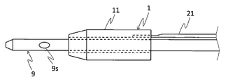
- the catheter 1 is roughly composed of a hollow shaft 11 and a core wire 21.
- a metal braid 31 for reinforcing the hollow shaft 11 and a coating 41 covering the braid 31 are aligned on the inner peripheral surface of the resin layer on the tip side of the tip of the core wire 21. Is illustrated.
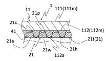
- the hollow shaft 11 is a hollow cylindrical member in which a plurality of resin layers including a first resin layer and a second resin layer are laminated. Specifically, for example, the hollow shaft 11 is provided on the inner circumference of the first resin layer 111 located at the outermost periphery and the first resin layer 111, and is inscribed in the first resin layer 111. It can be composed of two resin layers including the layer 112.
- the melt viscosity of the resin constituting the second resin layer 112 (hereinafter, also referred to as “second resin 112m”) is also referred to as the resin constituting the first resin layer 111 (hereinafter, also referred to as “first resin 111m”). ) Is configured to be smaller than the melt viscosity.
- the hardness of the resin constituting the first resin layer 111 is higher than the hardness of the resin constituting the second resin layer 112. As a result, the strength of the hollow shaft 11 is improved, the hollow shaft 11 is prevented from bending when the hollow shaft 11 is pushed by the core wire 21 (described later), and the pushability of the hollow shaft 11 can be further improved.
- the first and second resins 111m and 112m are related to the melt viscosity and hardness of the resin from, for example, polyamide, polyamide elastomer, polyolefin, polyester, polyester elastomer, polyurethane, silicone, fluororesin and the like, respectively. Can be selected to meet.
- the combination of the first and second resins 111m and 112m for example, two kinds of the above resins may be combined or the same kind of resin may be combined depending on the melt viscosity and hardness.
- the melt viscosity and hardness of the first and second resins can be adjusted by using resins of different grades.
- the core wire 21 is a member that is joined to the inner circumference of the hollow shaft 11 and has at least one through hole.
- the core wire 21 has, for example, a main body portion 21b having a substantially circular cross section and a thin plate-shaped tip portion 21t extending from the tip end of the main body portion 21b, and the tip portion 21t has a tip portion 21t. It can be configured to include a plurality of through holes 21h penetrating in the thickness direction (diameter direction of the hollow shaft 11).
- the core wire 21 can be arranged so that, for example, the main body portion 21b is located outside the base end side of the hollow shaft 11, and the tip end portion 21t is located in the middle of the hollow shaft 11 in the major axis direction. As shown in FIG.
- the tip portion 21t of the core wire 21 in the present embodiment is provided with two rows of through holes 21h along the long axis direction of the core wire 21.
- a handle (not shown) that can be gripped by the operator may be connected to the base end of the core wire 21.
- the material constituting the core wire 21 has a rigidity sufficient to securely push the hollow shaft 11 into the body cavity.
- the material constituting the core wire 21 include stainless steel such as SUS304, metal materials such as nickel titanium alloy and cobalt chromium alloy, and the like.
- second resin 112m a part of the above-mentioned second resin layer 112 (second resin 112m) is configured to penetrate into the through hole 21h. That is, the radial inner end 112a of the second resin layer 112 facing the through hole 21h is arranged so as to be closer to the central axis of the hollow shaft 11 than the radial outer end 21c of the through hole 21h. There is. It is preferable that a part of the second resin layer 112 penetrates into the inner wall 21w of the through hole 21h so as to adhere to the entire inner wall 21w of the through hole 21h. Is more preferable.
- the radial inner end 112a of the second resin layer 112 that has penetrated into the through hole 21h projects in the direction from the surface 21a of the core wire 21 (the surface closest to the central axis of the hollow shaft 11) toward the central axis. It is preferable that there is no such thing. Further, it is also preferable that the radial inner end portion 112a of the second resin layer 112 does not protrude from the surface 21a of the core wire 21 and has the same surface continuous with the surface 21a. Such a shape of the end portion 112a of the second resin layer 112 may allow the second resin layer 112 to penetrate into the through hole 21h, for example, with the end portion of the through hole 21h on the central axis side closed. , The second resin layer 112 can be obtained by invading the through hole 21h and then removing the protruding portion with a reamer or the like.
- a medical device for example, a guide wire or the like
- the medical device can be prevented from being caught in the through hole 21h.
- the opening area of the through hole 21h becomes smaller toward the inside in the radial direction of the hollow shaft 11.
- Examples of the shape of such a through hole 21h include a funnel shape and the like.
- the peripheral edge of the open end of the through hole 21h can be provided with a protruding portion 21p protruding toward the hollow shaft 11 side (diameterally outside of the hollow shaft 11).
- the protruding portion 21p bites into the hollow shaft 11 (for example, the second resin layer 112 or the like), so that the bonding strength between the hollow shaft 11 and the core wire 21 can be further increased.
- the protruding portion 21p can be formed in an annular shape over the entire peripheral edge of the open end of the through hole 21h, for example. As a result, the bonding strength between the hollow shaft 11 and the core wire 21 can be further increased by the amount that the protruding portion 21p bites into the hollow shaft 11.
- the catheter 1 can be manufactured, for example, by using a hollow shaft 11 and a core wire 21 molded into a predetermined shape and heat-bonding these members to each other.
- the heating temperature is preferably, for example, equal to or higher than the glass transition point from the viewpoint of improving the ease of penetration of the resin layers 111m and 112m into the through holes 21h.
- the pressure for crimping can be appropriately adjusted according to the state of penetration of the resin into the through hole 21h.
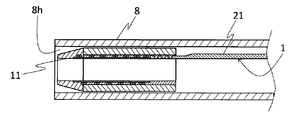
- the hollow shaft 11 of the catheter 1 is arranged in the lumen 8h of another catheter 8 (see FIG. 3A), and the core wire 21 is directed in the direction indicated by an arrow if necessary.
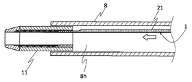
- the hollow shaft 11 is advanced from the tip of another catheter 8 by pushing it into the catheter 8 (see FIG. 3B), and the hollow shaft 11 is housed in the lumen 8h of the other catheter 8 by pulling the core wire 21.
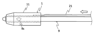
- the hollow shaft 11 is advanced by pushing the core wire 21 in the direction indicated by the arrow as necessary, and the opening 9s of the other medical device 9 is closed ( (See FIG. 4A), the hollow shaft 11 is retracted by pulling the core wire 21 to open the opening 9s of the other medical device 9 (see FIG. 4B).
- the catheter 1 can move the hollow shaft 11 back and forth in the body cavity by operating the core wire 21. Therefore, by using the catheter 1 in combination with another device (another catheter; another medical device such as a guide wire capture device, a stent delivery device, a balloon catheter, an endoscope), for example, of another catheter. It can be suitably used as an extension device whose tip can be substantially extended, and a coating device that covers the outer periphery of other medical devices in an openable and closable manner.
- another device another catheter; another medical device such as a guide wire capture device, a stent delivery device, a balloon catheter, an endoscope
- the catheter 1 since the catheter 1 has the above configuration, the second resin layer 112 can be easily and surely penetrated into the through hole 21h, and while maintaining good pushability in the body cavity, The bonding strength between the hollow shaft 11 and the core wire 21 can be improved.
- FIG. 5 is a schematic cross-sectional view showing a part of the second embodiment in an enlarged manner.
- the catheter 2 is roughly composed of a hollow shaft 12 and a core wire 21.
- the catheter 2 differs from the first embodiment in that it includes a hollow shaft 12. Since the core wire 21 has the same configuration as that of the first embodiment, the same parts are designated by the same reference numerals and detailed description thereof will be omitted. Further, since the configurations other than the configurations shown below are the same as those of the first embodiment, the description thereof will be omitted.
- the hollow shaft 12 is a hollow cylindrical member in which a plurality of resin layers including a first resin layer and a second resin layer provided on the inner circumference of the first resin layer are laminated.
- the melt viscosity of the resin constituting the second resin layer is configured to be smaller than the melt viscosity of the resin constituting the first resin layer. Further, a part of the second resin layer has penetrated into the through hole.
- the protruding portion 21p bites into the second resin layer 122 of the catheter 2. Therefore, the bonding strength between the hollow shaft 12 and the core wire 21 can be further increased.
- the catheter 2 since the catheter 2 has the above configuration, the amount of the first resin 121m having a melt viscosity larger than the melt viscosity of the second resin 122m invading the through hole 21h is contained in the body cavity.
- the pushability of the hollow shaft 12 of the above can be improved.
- the catheter (2) comprises a hollow shaft containing a resin layer and a core wire joined to the inner circumference of the hollow shaft and having at least one through hole, the opening area of the through hole being radially inward of the hollow shaft. It is characterized in that the resin layer becomes smaller toward the inside and a part of the resin layer penetrates into the through hole.
- the third and fourth embodiments relating to the catheter (2) will be described.
- FIG. 6 is a schematic cross-sectional view showing a part of the third embodiment in an enlarged manner.
- the catheter 3 is roughly composed of a hollow shaft 13 and a core wire 21.
- the catheter 3 differs from the first embodiment in that it includes a hollow shaft 13. Since the core wire 21 has the same configuration as that of the first embodiment, the same parts are designated by the same reference numerals and detailed description thereof will be omitted. Further, since the configurations other than the configurations shown below are the same as those of the first embodiment, the description thereof will be omitted.
- the hollow shaft 13 is a hollow cylindrical member including a resin layer.
- the hollow shaft 13 can be composed of, for example, one resin layer 131 made of one kind of resin.
- Examples of the resin 131 m constituting the resin layer 131 include polyamide, polyamide elastomer, polyolefin, polyester, polyester elastomer, polyurethane, silicone, and fluororesin.
- a part of the resin layer 131 (resin 131 m) is configured to penetrate into the through hole 21h of the core wire 21. That is, the radial inner end 131a of the resin layer 131 facing the through hole 21h is arranged so as to be closer to the central axis of the hollow shaft 13 than the radial outer end 21c of the through hole 21h.
- the protruding portion 21p bites into the resin layer 131 of the catheter 3. Therefore, the bonding strength between the hollow shaft 13 and the core wire 21 can be further increased.
- a part of the resin layer 131 penetrates so as to adhere to the inner wall 21w of the through hole 21h, and more preferably to penetrate the entire inner wall 21w of the through hole 21h.
- the radial inner end 131a of the resin layer 131 that has penetrated into the through hole 21h does not project in the direction from the surface 21a of the core wire 21 (the surface closest to the central axis of the hollow shaft 13) toward the central axis.
- the radial inner end 131a of the resin layer 131 constitutes the same surface continuous with the surface 21a of the core wire 21.
- the opening area of the through hole 21h becomes smaller toward the inside in the radial direction of the hollow shaft 13, so that a part of the resin 131m constituting the resin layer 131 is formed. Can be easily and surely penetrated into the through hole 21h, and the bonding strength between the hollow shaft 13 and the core wire 21 can be increased.
- FIG. 7 is a schematic cross-sectional view showing a part of the fourth embodiment in an enlarged manner.
- the catheter 4 is roughly composed of a hollow shaft 14 and a core wire 21.
- the catheter 4 differs from the third embodiment in that it includes a hollow shaft 14. Since the core wire 21 has the same configuration as that of the third embodiment, the same parts are designated by the same reference numerals and detailed description thereof will be omitted. Further, since the configurations other than the configurations shown below are the same as those of the third embodiment, the description thereof will be omitted.
- the hollow shaft 14 is a hollow cylindrical member including a resin layer.
- the resin layer of the catheter 4 is composed of a plurality of resin layers including a first resin layer 141 and a second resin layer 142 provided on the inner circumference of the first resin layer 141.
- the melt viscosity of the resin 142 m constituting the resin layer 142 of 2 is configured to be higher than the melt viscosity of the resin 141 m constituting the first resin layer 141.
- the melt viscosities of the resins satisfy the above relationship, respectively. You can choose.
- the combination of the first and second resins 141m and 142m for example, two kinds of the above resins may be combined or the same kind of resin may be combined depending on the melt viscosity.
- the melt viscosities of the first and second resins 141 m and 142 m can be adjusted by using different grade resins.
- second resin layer 142 (second resin 142m) is configured to penetrate into the through hole 21h. That is, the radial inner end 142a of the second resin layer 142 facing the through hole 21h is arranged so as to be closer to the central axis of the hollow shaft 14 than the radial outer end 21c of the through hole 21h. There is.
- the protruding portion 21p bites into the second resin layer 142 of the catheter 4. Therefore, the bonding strength between the hollow shaft 14 and the core wire 21 can be further increased.
- the second resin 142m existing in the through hole 21h is the through hole 21h because the melt viscosity of the resin 142m is larger than the melt viscosity of the first resin 141m. It is difficult to pull out from the hollow shaft 14, and the bonding strength between the hollow shaft 14 and the core wire 21 can be improved.
- the catheters 1 and 2 provided with the core wire 21 in which the opening area of the through hole 21h becomes smaller in the radial direction of the hollow shafts 11 and 12 have been described.
- the opening area of the through hole 210h may be constant over the entire thickness direction of the core wire 210 (see the catheter 101 in FIG. 8A).
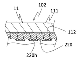
- the opening area of the through hole 220h may increase toward the inside in the radial direction of the hollow shaft 11 in the thickness direction of the core wire 220 (see the catheter 102 in FIG. 8B).
- the catheter provided with the braided body 31 and the coating 41 has been described.
- the catheter may not have the braided body 31 and the coating 41.
Landscapes
- Health & Medical Sciences (AREA)
- Life Sciences & Earth Sciences (AREA)
- Biophysics (AREA)
- Pulmonology (AREA)
- Engineering & Computer Science (AREA)
- Anesthesiology (AREA)
- Biomedical Technology (AREA)
- Heart & Thoracic Surgery (AREA)
- Hematology (AREA)
- Animal Behavior & Ethology (AREA)
- General Health & Medical Sciences (AREA)
- Public Health (AREA)
- Veterinary Medicine (AREA)
- Media Introduction/Drainage Providing Device (AREA)
Abstract
体腔内での良好な押し込み性を維持しつつ、中空シャフトとコアワイヤとの接合強度を向上させることが可能なカテーテルの提供を目的とする。 カテーテル1は、第1の樹脂層111と、第1の樹脂層111の内周に設けられた第2の樹脂層112と、を含む複数の樹脂層が積層された中空シャフト11と、中空シャフト11の内周に接合され、少なくとも1つの貫通孔21hを有するコアワイヤ21と、を備え、第2の樹脂層112を構成する樹脂112mの溶融粘度は、第1の樹脂層111を構成する樹脂111mの溶融粘度よりも小さく、第2の樹脂層112の一部が貫通孔21h内に侵入している。
Description
本発明は、カテーテルに関する。
コアワイヤの先端部に中空円筒形状の部材が取り付けられたカテーテルとして、例えば、ガイドエクステンションカテーテルなどが知られている(例えば、特許文献1参照)。
上述したカテーテルでは、コアワイヤとして基端シャフト、中空円筒形状の部材として先端シースが用いられ、先端シースは長さ方向に沿って硬さが異なるポリマーを用いて形成されている。上記基端シャフトと先端シースとは、穴が設けられた湾曲板状の結合部材を介して接合されている。
しかしながら、上述したような従来の技術では、先端シースの硬さが長さ方向に沿って異なっている。このため、先端シースの硬い部位では開口部へのポリマーの侵入不足により先端シースとコアワイヤとの接合強度が低下し、柔らかな部位では体腔内に押し込む際に先端シース自身が変形する(押し込み性が低下する)虞がある。
本発明は、以上のような事情に基づいてなされたものであり、その目的は、体腔内での良好な押し込み性を維持しつつ、中空シャフトとコアワイヤとの接合強度を向上させることが可能なカテーテルを提供することにある。
本開示のいくつかの態様は、
(1)第1の樹脂層と、前記第1の樹脂層の内周に設けられた第2の樹脂層と、を含む複数の樹脂層が積層された中空シャフトと、
前記中空シャフトの内周に接合され、少なくとも1つの貫通孔を有するコアワイヤと、を備え、
前記第2の樹脂層を構成する樹脂の溶融粘度は、前記第1の樹脂層を構成する樹脂の溶融粘度よりも小さく、
前記第2の樹脂層の一部が前記貫通孔内に侵入しているカテーテル、
(2)前記第1の樹脂層を構成する樹脂の硬さは、前記第2の樹脂層を構成する樹脂の硬さよりも大きい、前記(1)に記載のカテーテル、
(3)前記貫通孔の開口面積は、前記中空シャフトの径方向内側に向かって小さくなる、前記(1)または(2)に記載のカテーテル、および
(4)前記第1の樹脂層の一部が、前記貫通孔内に侵入している、前記(1)から(3)のいずれか一項に記載のカテーテル、である。
なお、本明細書において、「溶融粘度」とは、溶融した熱可塑性樹脂の流動性の指標であり、具体的には、JIS K7210-1(2014)に規定の「プラスチック-熱可塑性プラスチックのメルトマスフローレイト(MFR)及びメルトボリュームフローレイト(MVR)の求め方-第1部:標準的試験方法」を用いて測定したメルトマスフローレイト(MFR:Melt Mass-Flow Rate)を指す。「硬さ」とは、JIS Z2246(2000)に規定の「ショア硬さ試験-試験方法」を用いて測定したショアA硬さを意味する。
本発明は、体腔内での良好な押し込み性を維持しつつ、中空シャフトとコアワイヤとの接合強度を向上させることが可能なカテーテルを提供することができる。
以下、第1~第4の実施形態について図面を参照して説明するが、本発明は、当該図面に記載の実施形態にのみ限定されるものではない。なお、各図面に示したカテーテルの寸法は、実施内容の理解を容易にするために示した寸法であり、実際の寸法に対応するものではない。また、一部拡大概略的断面図は、中空シャフトとコアワイヤとの接合部を含む部位のみ図示している。
なお、本明細書において、「先端側」とは、体内に挿入される遠位方向を意味し、例えば、図1Aにおけるカテーテルの図示左方向を指す。「基端側」とは、先端側とは反対の方向を指す。
<カテーテル(1)>
カテーテル(1)は、第1の樹脂層と、上記第1の樹脂層の内周に設けられた第2の樹脂層と、を含む複数の樹脂層が積層された中空シャフトと、上記中空シャフトの内周に接合され、少なくとも1つの貫通孔を有するコアワイヤと、を備え、上記第2の樹脂層を構成する樹脂の溶融粘度は、上記第1の樹脂層を構成する樹脂の溶融粘度よりも小さく、上記第2の樹脂層の一部が上記貫通孔内に侵入していることを特徴とする。以下、カテーテル(1)に関する第1および第2の実施形態について説明する。
カテーテル(1)は、第1の樹脂層と、上記第1の樹脂層の内周に設けられた第2の樹脂層と、を含む複数の樹脂層が積層された中空シャフトと、上記中空シャフトの内周に接合され、少なくとも1つの貫通孔を有するコアワイヤと、を備え、上記第2の樹脂層を構成する樹脂の溶融粘度は、上記第1の樹脂層を構成する樹脂の溶融粘度よりも小さく、上記第2の樹脂層の一部が上記貫通孔内に侵入していることを特徴とする。以下、カテーテル(1)に関する第1および第2の実施形態について説明する。
[第1の実施形態]
図1は、カテーテルの第1の実施形態を示す概略的断面図である。当該カテーテル1は、図1A、図1Bに示すように、概略的に、中空シャフト11と、コアワイヤ21とにより構成されている。なお、図1Aには、コアワイヤ21の先端よりも先端側における樹脂層の内周面上に、中空シャフト11を補強するための金属製の編組体31、および編組体31を覆う被膜41が合わせて図示されている。
図1は、カテーテルの第1の実施形態を示す概略的断面図である。当該カテーテル1は、図1A、図1Bに示すように、概略的に、中空シャフト11と、コアワイヤ21とにより構成されている。なお、図1Aには、コアワイヤ21の先端よりも先端側における樹脂層の内周面上に、中空シャフト11を補強するための金属製の編組体31、および編組体31を覆う被膜41が合わせて図示されている。
中空シャフト11は、第1の樹脂層と第2の樹脂層とを含む複数の樹脂層が積層された中空円筒状の部材である。中空シャフト11は、具体的には、例えば、最も外周に位置する第1の樹脂層111と、第1の樹脂層111の内周に設けられ第1の樹脂層111に内接する第2の樹脂層112と、からなる2つの樹脂層で構成することができる。
第2の樹脂層112を構成する樹脂(以下、「第2の樹脂112m」ともいう)の溶融粘度は、第1の樹脂層111を構成する樹脂(以下、「第1の樹脂111m」ともいう)の溶融粘度よりも小さくなるように構成されている。
なお、第1の樹脂層111を構成する樹脂の硬度は、第2の樹脂層112を構成する樹脂の硬度よりも大きくなるように構成されていることが好ましい。これにより、中空シャフト11の強度が向上し、中空シャフト11をコアワイヤ21(後述)で押したときに中空シャフト11が曲がるのを防止し、中空シャフト11の押し込み性をより向上することができる。
第1および第2の樹脂111m,112mとしては、それぞれ、例えば、ポリアミド、ポリアミドエラストマー、ポリオレフィン、ポリエステル、ポリエステルエラストマー、ポリウレタン、シリコーン、フッ素樹脂等の中から、樹脂の溶融粘度や硬さが上記関係を満たすように選択することができる。
第1および第2の樹脂111m,112mの組み合わせとしては、溶融粘度や硬さに応じ、例えば、上記樹脂のうちの2種の樹脂を組み合わせてもよく、同種の樹脂を組み合わせてもよい。同種の樹脂を組み合わせる場合、グレードの異なる樹脂を使用することで、第1および第2の樹脂の溶融粘度や硬さを調整することができる。
コアワイヤ21は、中空シャフト11の内周に接合され、少なくとも1つの貫通孔を有する部材である。コアワイヤ21は、具体的には、例えば、断面が略円形な長手形状の本体部21bと、この本体部21bの先端から延設された薄板状の先端部21tとを有し、先端部21tがその厚み方向(中空シャフト11の径方向)に貫通する複数の貫通孔21hを具備するように構成することができる。コアワイヤ21は、例えば、本体部21bが中空シャフト11の基端側の外部に位置し、先端部21tの先端が中空シャフト11の長軸方向における中途に位置するように配置することができる。本実施形態におけるコアワイヤ21の先端部21tは、図2に示すように、コアワイヤ21の長軸方向に沿って2列の貫通孔21hが配設されている。コアワイヤ21の基端には、術者が把持可能なハンドル(不図示)が接続されていてもよい。
コアワイヤ21を構成する材料は、体腔内において中空シャフト11を確実に押し込める程度の剛性を有していることが好ましい。コアワイヤ21を構成する材料としては、例えば、SUS304などのステンレス鋼、ニッケルチタン合金、コバルトクロム合金などの金属材料等が挙げられる。
ここで、上述した第2の樹脂層112(第2の樹脂112m)の一部は、貫通孔21h内に侵入するように構成されている。すなわち、貫通孔21hに臨む第2の樹脂層112の径方向内側の端部112aは、貫通孔21hの径方向外側の端部21cよりも中空シャフト11の中心軸に近くなるように配置されている。なお、上記第2の樹脂層112の一部は、貫通孔21hの内壁21wに密着するように侵入していることが好ましく、貫通孔21hの内壁21w全体に密着するように侵入していることがより好ましい。
なお、貫通孔21hに侵入した第2の樹脂層112の径方向内側の端部112aは、コアワイヤ21の表面21a(中空シャフト11の中心軸に最も近い面)から上記中心軸に方向に突出していないことが好ましい。また、第2の樹脂層112の径方向内側の端部112aは、コアワイヤ21の表面21aから突出せず、かつ表面21aと連続する同一の面を構成されていることも好ましい。このような第2の樹脂層112の端部112aの形状は、例えば、貫通孔21hの上記中心軸側の端部を閉塞した状態で、貫通孔21hに第2の樹脂層112を侵入させたり、第2の樹脂層112を貫通孔21hに侵入させた後、突出した部位をリーマ等により除去することで得ることができる。
これにより、例えば、中空シャフト11の内腔をその長軸方向に沿って移動する医療用デバイス(例えば、ガイドワイヤなど)が、貫通孔21hに引っ掛かるのを防止することができ、上記医療用デバイスを円滑に進退させることができる。
貫通孔21hの開口面積は、中空シャフト11の径方向内側に向かって小さくなっていることが好ましい。このような貫通孔21hの形状としては、例えば、漏斗形状等が挙げられる。これにより、第2の樹脂層112の一部を貫通孔21hに容易かつ確実に侵入させることができ、中空シャフト11とコアワイヤ21との接合強度をより向上させることができる。
また、貫通孔21hの開口端周縁部の少なくとも一部には、中空シャフト11の側(中空シャフト11の径方向外側)に突き出る突出部21pを設けることができる。このように突出部21pを設けることで、突出部21pが中空シャフト11(例えば、第2の樹脂層112等)に食い込むため、中空シャフト11とコアワイヤ21との接合強度をより高めることができる。突出部21pは、例えば、貫通孔21hの開口端周縁部の全体に亘って環状に形成することができる。これにより、突出部21pが中空シャフト11により食い込む分、中空シャフト11とコアワイヤ21との接合強度をさらに高めることができる。
次に、当該カテーテル1の製造方法について説明する。当該カテーテル1は、例えば、所定形状に成形された中空シャフト11およびコアワイヤ21を用い、これらの部材どうしを加熱圧着することで製造することができる。加熱する温度は、貫通孔21hへの樹脂層111m,112mの侵入容易性向上の観点から、例えば、ガラス転移点以上であることが好ましい。圧着する圧力は、貫通孔21hへの樹脂の侵入状態に応じて適宜調整することができる。
次に、当該カテーテル1の使用態様について説明する。例えば、当該カテーテル1を延長用のデバイスとして用いる場合、当該カテーテル1の中空シャフト11を他のカテーテル8の内腔8h内に配置し(図3A参照)、必要に応じてコアワイヤ21を矢示方向に押し込むことで中空シャフト11を他のカテーテル8の先端から進出させたり(図3B参照)、コアワイヤ21を引っ張ることで中空シャフト11を他のカテーテル8の内腔8h内に収納させる。
また、当該カテーテル1を被覆用のデバイスとして用いる場合、必要に応じてコアワイヤ21を矢示方向に押し込むことで中空シャフト11を進出させて他の医療用デバイス9の開口部9sを閉塞したり(図4A参照)、コアワイヤ21を引っ張ることで中空シャフト11を後退させて上記他の医療用デバイス9の開口部9sを開放する(図4B参照)。
このように、当該カテーテル1は、コアワイヤ21を操作することで体腔内にて中空シャフト11を進退させることができる。このため、当該カテーテル1を他のデバイス(他のカテーテル;ガイドワイヤ捕獲デバイス、ステントデリバリーデバイス、バルーンカテーテル、内視鏡などの他の医療用デバイス)と併用することで、例えば、他のカテーテルの先端を実質的に延長可能な延長用のデバイス、他の医療用デバイスの外周を開閉可能に覆う被覆用のデバイスとして好適に用いることができる。
以上のように、当該カテーテル1は、上記構成であるので、第2の樹脂層112を貫通孔21hに容易かつ確実に侵入させることができ、体腔内での良好な押し込み性を維持しつつ、中空シャフト11とコアワイヤ21との接合強度を向上させることができる。
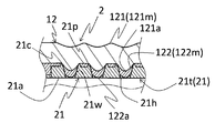
[第2の実施形態]
図5は、第2の実施形態の一部を拡大して示す概略的断面図である。当該カテーテル2は、図5に示すように、概略的に、中空シャフト12と、コアワイヤ21とにより構成されている。当該カテーテル2は、中空シャフト12を備えている点で、第1の実施形態と異なっている。なお、コアワイヤ21は、第1の実施形態のものと同様の構成であるため、同一部分には同一符号を付してその詳細な説明は省略する。また、以下に示す構成以外の構成は、第1の実施形態のものと同様であるのでその説明を省略する。
図5は、第2の実施形態の一部を拡大して示す概略的断面図である。当該カテーテル2は、図5に示すように、概略的に、中空シャフト12と、コアワイヤ21とにより構成されている。当該カテーテル2は、中空シャフト12を備えている点で、第1の実施形態と異なっている。なお、コアワイヤ21は、第1の実施形態のものと同様の構成であるため、同一部分には同一符号を付してその詳細な説明は省略する。また、以下に示す構成以外の構成は、第1の実施形態のものと同様であるのでその説明を省略する。
中空シャフト12は、第1の樹脂層と、第1の樹脂層の内周に設けられた第2の樹脂層と、を含む複数の樹脂層が積層された中空円筒状の部材である。第2の樹脂層を構成する樹脂の溶融粘度は、第1の樹脂層を構成する樹脂の溶融粘度よりも小さくなるように構成されている。また、第2の樹脂層の一部は、貫通孔内に侵入している。
本実施形態の中空シャフト12は、第2の樹脂層122(第2の樹脂122m)の一部と共に第1の樹脂層121(第1の樹脂121m)の一部が貫通孔21h内に侵入するように構成されている。すなわち、貫通孔21hに臨む第1の樹脂層121の径方向内側の端部121aは、貫通孔21hの径方向外側の端部21cよりも中空シャフト12の中心軸に近くなるように配置されている。
なお、当該カテーテル2の第2の樹脂層122には、突出部21pが食い込んでいる。このため、中空シャフト12とコアワイヤ21との接合強度をより高めることができる。
以上のように、当該カテーテル2は、上記構成であるので、第2の樹脂122mの溶融粘度よりも大きい溶融粘度を有する第1の樹脂121mが貫通孔21hに侵入している分、体腔内での中空シャフト12の押し込み性を向上することができる。
<カテーテル(2)>
カテーテル(2)は、樹脂層を含む中空シャフトと、中空シャフトの内周に接合され、少なくとも1つの貫通孔を有するコアワイヤと、を備え、貫通孔の開口面積は、中空シャフトの径方向内側に向かって小さくなっており、樹脂層の一部が貫通孔内に侵入していることを特徴とする。以下、カテーテル(2)に関する第3および第4の実施形態について説明する。
カテーテル(2)は、樹脂層を含む中空シャフトと、中空シャフトの内周に接合され、少なくとも1つの貫通孔を有するコアワイヤと、を備え、貫通孔の開口面積は、中空シャフトの径方向内側に向かって小さくなっており、樹脂層の一部が貫通孔内に侵入していることを特徴とする。以下、カテーテル(2)に関する第3および第4の実施形態について説明する。
[第3の実施形態]
図6は、第3の実施形態の一部を拡大して示す概略的断面図である。当該カテーテル3は、図6に示すように、概略的に、中空シャフト13と、コアワイヤ21とにより構成されている。当該カテーテル3は、中空シャフト13を備えている点で、第1の実施形態と異なっている。なお、コアワイヤ21は、第1の実施形態のものと同様の構成であるため、同一部分には同一符号を付してその詳細な説明は省略する。また、以下に示す構成以外の構成は、第1の実施形態のものと同様であるのでその説明を省略する。
図6は、第3の実施形態の一部を拡大して示す概略的断面図である。当該カテーテル3は、図6に示すように、概略的に、中空シャフト13と、コアワイヤ21とにより構成されている。当該カテーテル3は、中空シャフト13を備えている点で、第1の実施形態と異なっている。なお、コアワイヤ21は、第1の実施形態のものと同様の構成であるため、同一部分には同一符号を付してその詳細な説明は省略する。また、以下に示す構成以外の構成は、第1の実施形態のものと同様であるのでその説明を省略する。
中空シャフト13は、樹脂層を含む中空円筒状の部材である。中空シャフト13は、具体的には、例えば、1種類の樹脂で形成された1つの樹脂層131で構成することができる。
樹脂層131を構成する樹脂131mとしては、例えば、ポリアミド、ポリアミドエラストマー、ポリオレフィン、ポリエステル、ポリエステルエラストマー、ポリウレタン、シリコーン、フッ素樹脂等が挙げられる。
ここで、樹脂層131(樹脂131m)の一部は、コアワイヤ21の貫通孔21h内に侵入するように構成されている。すなわち、貫通孔21hに臨む樹脂層131の径方向内側の端部131aは、貫通孔21hの径方向外側の端部21cよりも中空シャフト13の中心軸に近くなるように配置されている。
また、当該カテーテル3の樹脂層131には、突出部21pが食い込んでいる。このため、中空シャフト13とコアワイヤ21との接合強度をより高めることができる。
なお、樹脂層131の一部は、貫通孔21hの内壁21wに密着するように侵入していることが好ましく、貫通孔21hの内壁21w全体に密着するように侵入していることがより好ましい。また、貫通孔21hに侵入した樹脂層131の径方向内側の端部131aは、コアワイヤ21の表面21a(中空シャフト13の中心軸に最も近い面)から上記中心軸に方向に突出していないことが好ましい。また、樹脂層131の径方向内側の端部131aは、コアワイヤ21の表面21aと連続する同一の面を構成することも好ましい。
以上のように、当該カテーテル3は、上記構成であるので、貫通孔21hの開口面積が中空シャフト13の径方向内側に向かって小さくなっている分、樹脂層131を構成する樹脂131mの一部を貫通孔21hに容易かつ確実に侵入させることができ、中空シャフト13とコアワイヤ21との接合強度を高めることができる。
[第4の実施形態]
図7は、第4の実施形態の一部を拡大して示す概略的断面図である。当該カテーテル4は、図7に示すように、概略的に、中空シャフト14と、コアワイヤ21とにより構成されている。当該カテーテル4は、中空シャフト14を備えている点で、第3の実施形態と異なっている。なお、コアワイヤ21は、第3の実施形態のものと同様の構成であるため、同一部分には同一符号を付してその詳細な説明は省略する。また、以下に示す構成以外の構成は、第3の実施形態のものと同様であるのでその説明を省略する。
図7は、第4の実施形態の一部を拡大して示す概略的断面図である。当該カテーテル4は、図7に示すように、概略的に、中空シャフト14と、コアワイヤ21とにより構成されている。当該カテーテル4は、中空シャフト14を備えている点で、第3の実施形態と異なっている。なお、コアワイヤ21は、第3の実施形態のものと同様の構成であるため、同一部分には同一符号を付してその詳細な説明は省略する。また、以下に示す構成以外の構成は、第3の実施形態のものと同様であるのでその説明を省略する。
中空シャフト14は、樹脂層を含む中空円筒状の部材である。当該カテーテル4の樹脂層は、第1の樹脂層141と、第1の樹脂層141の内周に設けられた第2の樹脂層142と、を含む複数の樹脂層から構成されており、第2の樹脂層142を構成する樹脂142mの溶融粘度は、第1の樹脂層141を構成する樹脂141mの溶融粘度よりも大きくなるように構成されている。
第1および第2の樹脂141m,142mとしては、それぞれ、例えば、第1の実施形態において例示した第1および第2の樹脂111m,112mの中から、樹脂の溶融粘度が上記関係を満たすように選択することができる。
第1および第2の樹脂141m,142mの組み合わせとしては、溶融粘度に応じ、例えば、上記樹脂のうちの2種の樹脂を組み合わせてもよく、同種の樹脂を組み合わせてもよい。同種の樹脂を組み合わせる場合、グレードの異なる樹脂を使用することで、第1および第2の樹脂141m,142mの溶融粘度を調整することができる。
また、上述した第2の樹脂層142(第2の樹脂142m)の一部は、貫通孔21h内に侵入するように構成されている。すなわち、貫通孔21hに臨む第2の樹脂層142の径方向内側の端部142aは、貫通孔21hの径方向外側の端部21cよりも中空シャフト14の中心軸に近くなるように配置されている。
また、当該カテーテル4の第2の樹脂層142には、突出部21pが食い込んでいる。このため、中空シャフト14とコアワイヤ21との接合強度をより高めることができる。
以上のように、当該カテーテル4は、上記構成であるので、樹脂142mの溶融粘度が第1の樹脂141mの溶融粘度よりも大きい分、貫通孔21h内に存する第2の樹脂142mが貫通孔21hから抜け難く、中空シャフト14とコアワイヤ21との接合強度を向上させることができる。
なお、本発明は、上述した実施形態の構成に限定されるものではなく、特許請求の範囲によって示され、特許請求の範囲と均等の意味および範囲内での全ての変更が含まれることが意図される。
例えば、上述した第1および第2の実施形態では、貫通孔21hの開口面積が中空シャフト11,12の径方向内側に向かって小さくなっているコアワイヤ21を備えたカテーテル1,2について説明した。しかしながら、カテーテル(1)においては、貫通孔210hの開口面積は、コアワイヤ210の厚み方向全体に亘って一定(貫通孔210hが円柱状)であってもよい(図8Aのカテーテル101参照)。また、貫通孔220hの開口面積は、コアワイヤ220の厚み方向における中空シャフト11の径方向内側に向かって大きくなっていてもよい(図8Bのカテーテル102参照)。
また、上述した実施形態では、編組体31および被膜41が設けられたカテーテルについて説明した。しかしながら、当該カテーテルは、編組体31および被膜41を有しないものであってもよい。
1~4,101,102 カテーテル
11~14 中空シャフト
111,121,131,141 第1の樹脂層
112,122,142 第2の樹脂層
21,210,220 コアワイヤ
21h,210h,220h 貫通孔
11~14 中空シャフト
111,121,131,141 第1の樹脂層
112,122,142 第2の樹脂層
21,210,220 コアワイヤ
21h,210h,220h 貫通孔
Claims (4)
- 第1の樹脂層と、前記第1の樹脂層の内周に設けられた第2の樹脂層と、を含む複数の樹脂層が積層された中空シャフトと、
前記中空シャフトの内周に接合され、少なくとも1つの貫通孔を有するコアワイヤと、を備え、
前記第2の樹脂層を構成する樹脂の溶融粘度は、前記第1の樹脂層を構成する樹脂の溶融粘度よりも小さく、
前記第2の樹脂層の一部が前記貫通孔内に侵入しているカテーテル。 - 前記第1の樹脂層を構成する樹脂の硬さは、前記第2の樹脂層を構成する樹脂の硬さよりも大きい、請求項1に記載のカテーテル。
- 前記貫通孔の開口面積は、前記中空シャフトの径方向内側に向かって小さくなる、請求項1または請求項2に記載のカテーテル。
- 前記第1の樹脂層の一部が、前記貫通孔内に侵入している、請求項1から請求項3のいずれか一項に記載のカテーテル。
Applications Claiming Priority (2)
| Application Number | Priority Date | Filing Date | Title |
|---|---|---|---|
| JP2020-000557 | 2020-01-06 | ||
| JP2020000557A JP2021108750A (ja) | 2020-01-06 | 2020-01-06 | カテーテル |
Publications (1)
| Publication Number | Publication Date |
|---|---|
| WO2021140883A1 true WO2021140883A1 (ja) | 2021-07-15 |
Family
ID=76787466
Family Applications (1)
| Application Number | Title | Priority Date | Filing Date |
|---|---|---|---|
| PCT/JP2020/047517 WO2021140883A1 (ja) | 2020-01-06 | 2020-12-18 | カテーテル |
Country Status (2)
| Country | Link |
|---|---|
| JP (1) | JP2021108750A (ja) |
| WO (1) | WO2021140883A1 (ja) |
Citations (2)
| Publication number | Priority date | Publication date | Assignee | Title |
|---|---|---|---|---|
| JP2001178826A (ja) * | 1999-12-27 | 2001-07-03 | Hirakawa Hewtech Corp | カテーテル用チューブ |
| JP2012510329A (ja) * | 2008-12-03 | 2012-05-10 | アンジオメト・ゲーエムベーハー・ウント・コンパニー・メディツィンテクニク・カーゲー | 伸縮自在なカテーテル |
Family Cites Families (1)
| Publication number | Priority date | Publication date | Assignee | Title |
|---|---|---|---|---|
| JP5818530B2 (ja) * | 2011-06-22 | 2015-11-18 | 株式会社グッドマン | カテーテル |
-
2020
- 2020-01-06 JP JP2020000557A patent/JP2021108750A/ja active Pending
- 2020-12-18 WO PCT/JP2020/047517 patent/WO2021140883A1/ja active Application Filing
Patent Citations (2)
| Publication number | Priority date | Publication date | Assignee | Title |
|---|---|---|---|---|
| JP2001178826A (ja) * | 1999-12-27 | 2001-07-03 | Hirakawa Hewtech Corp | カテーテル用チューブ |
| JP2012510329A (ja) * | 2008-12-03 | 2012-05-10 | アンジオメト・ゲーエムベーハー・ウント・コンパニー・メディツィンテクニク・カーゲー | 伸縮自在なカテーテル |
Also Published As
| Publication number | Publication date |
|---|---|
| JP2021108750A (ja) | 2021-08-02 |
Similar Documents
| Publication | Publication Date | Title |
|---|---|---|
| JP5225848B2 (ja) | マイクロカテーテル | |
| EP2015821B1 (en) | Removable valves and methods for making them | |
| US6210396B1 (en) | Guiding catheter with tungsten loaded band | |
| EP3632494A1 (en) | Catheter | |
| WO2013146673A1 (ja) | 医療機器および医療機器の製造方法 | |
| EP3546008A1 (en) | Catheter and method for manufacturing catheter | |
| US10695531B2 (en) | Balloon catheter and medical elongated body | |
| JP6248630B2 (ja) | バルーンカテーテルとその製造方法 | |
| WO2013100045A1 (ja) | ガイドワイヤ | |
| JPH10511871A (ja) | 軟質チップ形成方法 | |
| EP2928380B1 (en) | Reinforced catheter transition with flexible tip portion | |
| WO2013118649A1 (ja) | ガイドワイヤ | |
| WO2018092386A1 (ja) | カテーテルおよびカテーテルの製造方法 | |
| JP2016116814A (ja) | バルーンカテーテル | |
| JP2001178826A (ja) | カテーテル用チューブ | |
| WO2021140883A1 (ja) | カテーテル | |
| JP2013165926A (ja) | 医療機器 | |
| JP2013132432A (ja) | 医療機器および医療機器の製造方法 | |
| JP5124703B2 (ja) | 医療用ステントおよび医療用ステントの製造方法 | |
| JP2012045043A (ja) | 医療用器具 | |
| JP6319390B2 (ja) | 医療機器および医療機器の製造方法 | |
| JP6713418B2 (ja) | カテーテル | |
| JP2014188216A (ja) | 医療用機器および医療用機器の製造方法 | |
| JP7064816B2 (ja) | カテーテル | |
| JP2012020068A (ja) | チューブおよびカテーテル |
Legal Events
| Date | Code | Title | Description |
|---|---|---|---|
| 121 | Ep: the epo has been informed by wipo that ep was designated in this application |
Ref document number: 20912721 Country of ref document: EP Kind code of ref document: A1 |
|
| NENP | Non-entry into the national phase |
Ref country code: DE |
|
| 122 | Ep: pct application non-entry in european phase |
Ref document number: 20912721 Country of ref document: EP Kind code of ref document: A1 |