WO2021140829A1 - 吐出弁機構及びそれを備えた高圧燃料供給ポンプ - Google Patents
吐出弁機構及びそれを備えた高圧燃料供給ポンプ Download PDFInfo
- Publication number
- WO2021140829A1 WO2021140829A1 PCT/JP2020/046235 JP2020046235W WO2021140829A1 WO 2021140829 A1 WO2021140829 A1 WO 2021140829A1 JP 2020046235 W JP2020046235 W JP 2020046235W WO 2021140829 A1 WO2021140829 A1 WO 2021140829A1
- Authority
- WO
- WIPO (PCT)
- Prior art keywords
- valve
- discharge valve
- flow path
- hole
- valve body
- Prior art date
- Legal status (The legal status is an assumption and is not a legal conclusion. Google has not performed a legal analysis and makes no representation as to the accuracy of the status listed.)
- Ceased
Links
Images




Classifications
-
- F—MECHANICAL ENGINEERING; LIGHTING; HEATING; WEAPONS; BLASTING
- F02—COMBUSTION ENGINES; HOT-GAS OR COMBUSTION-PRODUCT ENGINE PLANTS
- F02M—SUPPLYING COMBUSTION ENGINES IN GENERAL WITH COMBUSTIBLE MIXTURES OR CONSTITUENTS THEREOF
- F02M59/00—Pumps specially adapted for fuel-injection and not provided for in groups F02M39/00 -F02M57/00, e.g. rotary cylinder-block type of pumps
- F02M59/44—Details, components parts, or accessories not provided for in, or of interest apart from, the apparatus of groups F02M59/02 - F02M59/42; Pumps having transducers, e.g. to measure displacement of pump rack or piston
- F02M59/46—Valves
- F02M59/462—Delivery valves
-
- F—MECHANICAL ENGINEERING; LIGHTING; HEATING; WEAPONS; BLASTING
- F02—COMBUSTION ENGINES; HOT-GAS OR COMBUSTION-PRODUCT ENGINE PLANTS
- F02M—SUPPLYING COMBUSTION ENGINES IN GENERAL WITH COMBUSTIBLE MIXTURES OR CONSTITUENTS THEREOF
- F02M63/00—Other fuel-injection apparatus having pertinent characteristics not provided for in groups F02M39/00 - F02M57/00 or F02M67/00; Details, component parts, or accessories of fuel-injection apparatus, not provided for in, or of interest apart from, the apparatus of groups F02M39/00 - F02M61/00 or F02M67/00; Combination of fuel pump with other devices, e.g. lubricating oil pump
- F02M63/0012—Valves
- F02M63/007—Details not provided for in, or of interest apart from, the apparatus of the groups F02M63/0014 - F02M63/0059
-
- F—MECHANICAL ENGINEERING; LIGHTING; HEATING; WEAPONS; BLASTING
- F02—COMBUSTION ENGINES; HOT-GAS OR COMBUSTION-PRODUCT ENGINE PLANTS
- F02M—SUPPLYING COMBUSTION ENGINES IN GENERAL WITH COMBUSTIBLE MIXTURES OR CONSTITUENTS THEREOF
- F02M63/00—Other fuel-injection apparatus having pertinent characteristics not provided for in groups F02M39/00 - F02M57/00 or F02M67/00; Details, component parts, or accessories of fuel-injection apparatus, not provided for in, or of interest apart from, the apparatus of groups F02M39/00 - F02M61/00 or F02M67/00; Combination of fuel pump with other devices, e.g. lubricating oil pump
- F02M63/0012—Valves
- F02M63/007—Details not provided for in, or of interest apart from, the apparatus of the groups F02M63/0014 - F02M63/0059
- F02M63/0071—Details not provided for in, or of interest apart from, the apparatus of the groups F02M63/0014 - F02M63/0059 characterised by guiding or centering means in valves including the absence of any guiding means, e.g. "flying arrangements"
-
- F—MECHANICAL ENGINEERING; LIGHTING; HEATING; WEAPONS; BLASTING
- F02—COMBUSTION ENGINES; HOT-GAS OR COMBUSTION-PRODUCT ENGINE PLANTS
- F02M—SUPPLYING COMBUSTION ENGINES IN GENERAL WITH COMBUSTIBLE MIXTURES OR CONSTITUENTS THEREOF
- F02M63/00—Other fuel-injection apparatus having pertinent characteristics not provided for in groups F02M39/00 - F02M57/00 or F02M67/00; Details, component parts, or accessories of fuel-injection apparatus, not provided for in, or of interest apart from, the apparatus of groups F02M39/00 - F02M61/00 or F02M67/00; Combination of fuel pump with other devices, e.g. lubricating oil pump
- F02M63/0012—Valves
- F02M63/007—Details not provided for in, or of interest apart from, the apparatus of the groups F02M63/0014 - F02M63/0059
- F02M63/0075—Stop members in valves, e.g. plates or disks limiting the movement of armature, valve or spring
-
- F—MECHANICAL ENGINEERING; LIGHTING; HEATING; WEAPONS; BLASTING
- F02—COMBUSTION ENGINES; HOT-GAS OR COMBUSTION-PRODUCT ENGINE PLANTS
- F02M—SUPPLYING COMBUSTION ENGINES IN GENERAL WITH COMBUSTIBLE MIXTURES OR CONSTITUENTS THEREOF
- F02M63/00—Other fuel-injection apparatus having pertinent characteristics not provided for in groups F02M39/00 - F02M57/00 or F02M67/00; Details, component parts, or accessories of fuel-injection apparatus, not provided for in, or of interest apart from, the apparatus of groups F02M39/00 - F02M61/00 or F02M67/00; Combination of fuel pump with other devices, e.g. lubricating oil pump
- F02M63/0012—Valves
- F02M63/007—Details not provided for in, or of interest apart from, the apparatus of the groups F02M63/0014 - F02M63/0059
- F02M63/0077—Valve seat details
-
- F—MECHANICAL ENGINEERING; LIGHTING; HEATING; WEAPONS; BLASTING
- F02—COMBUSTION ENGINES; HOT-GAS OR COMBUSTION-PRODUCT ENGINE PLANTS
- F02M—SUPPLYING COMBUSTION ENGINES IN GENERAL WITH COMBUSTIBLE MIXTURES OR CONSTITUENTS THEREOF
- F02M63/00—Other fuel-injection apparatus having pertinent characteristics not provided for in groups F02M39/00 - F02M57/00 or F02M67/00; Details, component parts, or accessories of fuel-injection apparatus, not provided for in, or of interest apart from, the apparatus of groups F02M39/00 - F02M61/00 or F02M67/00; Combination of fuel pump with other devices, e.g. lubricating oil pump
- F02M63/0012—Valves
- F02M63/007—Details not provided for in, or of interest apart from, the apparatus of the groups F02M63/0014 - F02M63/0059
- F02M63/0078—Valve member details, e.g. special shape, hollow or fuel passages in the valve member
Definitions
- the present invention relates to a discharge valve mechanism and a high-pressure fuel supply pump provided with the discharge valve mechanism.
- a high-pressure fuel supply pump for increasing the pressure of fuel is widely used.
- a discharge valve unit that constitutes a part of a high-pressure fuel supply pump, a seat member having a seat surface, a discharge valve member that comes into contact with and separates from the seat surface, and a discharge valve member that urges the discharge valve member toward the seat surface side.
- a simple configuration including a valve spring and a valve housing for accommodating these three members has been proposed (see, for example, Patent Document 1).
- the valve housing of the discharge valve unit slides at the maximum diameter position of the discharge valve member in order to suppress a severe displacement of the valve in the crossing direction of the stroke axis when the valve is opened and closed.
- the seat member is held on the inner diameter side so that the central axis of the seat surface of the seat member overlaps with the stroke axis of the discharge valve member, and the discharge valve unit further holds the discharge valve member.
- the seat member are held and unitized, and are press-fitted and fixed to the inner peripheral surface of the opening connected to the discharge valve unit formed in the pump housing.
- a valve housing discharge hole (passage) is provided in a portion of the valve housing on the discharge port side (discharge side tip) in the extending direction of the stroke axis.
- the valve is opened by moving the discharge valve member along the regulation part due to the fuel differential pressure before and after the stroke axis of the discharge valve member (the space on the pressurizing chamber side and the space on the discharge port side of the high-pressure fuel supply pump). To do.
- the discharge valve member is opened, the fuel in the pressurizing chamber passes through the valve housing discharge hole (passage) provided on the side surface of the valve housing on the upstream side of the regulation portion or in the middle portion of the regulation portion and is discharged. It is pumped to the outlet.
- a discharge valve unit having such a structure if the front-rear fuel differential pressure on the stroke axis is not sufficient when the discharge valve member is opened, the required lift amount of the discharge valve member cannot be secured or the valve is opened. There is concern that the movement will be slow.
- the high-pressure fuel supply pump is operating at a large flow rate or high speed, if the lift amount at the time of opening the discharge valve member is small and the valve opening operation is slow, the pressure in the pressurizing chamber rises more than necessary. In this case, various parts constituting the high-pressure fuel supply pump may be subjected to an unnecessarily high-pressure load, or the efficiency of the high-pressure fuel supply pump may be lowered.
- the discharge port of the pump is located in the extending direction of the stroke axis of the discharge valve unit.
- some high-pressure fuel supply pumps have a structure in which the discharge port is not in the extending direction of the stroke axis of the discharge valve unit and is provided at a position deviated from the discharge valve unit. In such a structure, the pressure on the discharge port side cannot be guided even if the valve housing discharge hole is provided in the extending direction of the stroke axis in the valve housing as in the discharge valve unit described in Patent Document 1, and therefore, it is usually used.
- a structure is provided to prevent the flow of fuel through the discharge hole of the valve housing.
- the fuel pressure on the secondary side of the discharge valve member in the valve housing rises with the movement of the discharge valve member on the stroke axis when the valve is opened. Therefore, it is particularly difficult to sufficiently secure the front and rear fuel differential pressure on the stroke axis of the discharge valve member.
- the present invention has been made to solve the above problems, and an object of the present invention is a discharge valve mechanism capable of improving the responsiveness when the discharge valve is opened and a high-pressure fuel supply pump provided with the discharge valve mechanism. Is to provide.
- a valve seat portion having a primary side flow path and a valve body capable of seating and leaving the valve seat portion.
- a guide portion that is formed so as to be slidable on the outer surface of the valve body and guides the movement of the valve body in the contacting / separating direction with respect to the valve seat portion, and the guide portion has a gap with the outer surface of the valve body.
- a first secondary flow path that includes a portion set to be equal to or less than a predetermined value and communicates an internal space upstream of the guide portion with an external flow path is lateral to the valve body in the moving direction.
- the second secondary flow path which is formed so as to allow the fluid to flow out and communicates the internal space downstream of the guide portion with the external flow path, fluids laterally in the moving direction of the valve body. It is characterized in that it is formed so as to let out.
- the guide portion functions as a flow throttle to cause a pressure drop of the fluid. Therefore, the internal space before and after the valve body in the moving direction (internal space on the upstream side and downstream side of the guide portion) is correspondingly large. The fluid differential pressure in the interior space) is further increased. Therefore, since the valve opening operation of the valve body becomes faster due to the increased fluid differential pressure, the responsiveness at the time of valve opening of the discharge valve mechanism can be improved. Issues, configurations and effects other than the above will be clarified by the following description of the embodiments.
- FIG. 2 is a cross-sectional view of the high-pressure fuel supply pump according to the first embodiment of the present invention shown in FIG. 2 as viewed from the arrow III-III.
- FIG. 3 is a cross-sectional view showing an enlarged state of the discharge valve mechanism according to the first embodiment of the present invention shown in FIG. It is a perspective view which shows the discharge valve mechanism which concerns on 1st Embodiment of this invention in the disassembled state.
- FIG. 5 is a cross-sectional view of the discharge valve mechanism according to the second embodiment of the present invention cut in a plane including a second through hole different from the cut surface shown in FIG. It is a perspective view which shows the discharge valve holder which constitutes a part of the discharge valve mechanism which concerns on 2nd Embodiment of this invention.
- FIG. 1 is a configuration diagram showing a fuel supply system of an internal combustion engine including a high-pressure fuel supply pump according to the first embodiment of the present invention.
- FIG. 1 is a diagram schematically showing the configuration of the fuel supply system, and the configuration of the high-pressure fuel supply pump shown in FIG. 1 is different from the configurations shown in FIGS. 2 and later described later.
- the fuel supply system of the internal combustion engine pressurizes, for example, a fuel tank 101 for storing fuel, a feed pump 102 for pumping and delivering fuel in the fuel tank 101, and fuel sent from the feed pump 102. It includes a high-pressure fuel supply pump 1 that discharges fuel, and a plurality of injectors 103 that inject high-pressure fuel pumped from the high-pressure fuel supply pump 1.
- the high-pressure fuel supply pump 1 is connected to the feed pump 102 via the suction pipe 104 and is connected to the injector 103 via the common rail 105.
- the injector 103 is mounted on the common rail 105 according to the number of cylinders of the engine.
- the common rail 105 is equipped with a pressure sensor 106 that detects the pressure of the fuel discharged from the high-pressure fuel supply pump 1.
- This system is a so-called direct injection engine system that injects fuel directly into the cylinder cylinder of the engine.
- the high-pressure fuel supply pump 1 includes a pump body 1a having a pressurizing chamber 3 for pressurizing fuel inside, a plunger 4, an electromagnetic suction valve mechanism 300, and a discharge valve mechanism 500 assembled to the pump body 1a. There is.
- the plunger 4 pressurizes the fuel in the pressurizing chamber 3 by reciprocating motion.
- the solenoid valve mechanism 300 functions as a capacity variable mechanism for adjusting the flow rate of fuel sucked into the pressurizing chamber 3.
- the discharge valve mechanism 500 discharges the fuel pressurized by the plunger 4 to the common rail 105 side.
- a damper 12 is provided as a pressure pulsation reducing mechanism for reducing the pressure pulsation generated in the high-pressure fuel supply pump 1 from spreading to the suction pipe 104.
- the feed pump 102, the solenoid valve mechanism 300 of the high-pressure fuel supply pump 1, and the injector 103 are electrically connected to an engine control unit (hereinafter referred to as an ECU) 107, and are controlled by a control signal output from the ECU 107.
- a detection signal from the pressure sensor 106 is input to the ECU 107.
- the fuel in the fuel tank 101 is pumped up by the feed pump 102 driven based on the control signal of the ECU 107.
- This fuel is pressurized to an appropriate feed pressure by the feed pump 102 and sent to the low pressure fuel suction port 2a of the high pressure fuel supply pump 1 through the suction pipe 104.
- the fuel that has passed through the low-pressure fuel suction port 2a reaches the suction port 31c of the solenoid valve mechanism 300 via the damper 12 and the suction passage 2d.
- the fuel that has flowed into the solenoid valve mechanism 300 passes through an opening that is opened and closed by the suction valve 30.
- This fuel is sucked into the pressurizing chamber 3 in the descending stroke of the reciprocating plunger 4, and is pressurized in the pressurizing chamber 3 in the ascending stroke of the plunger 4.
- the pressurized fuel is pumped to the common rail 105 via the discharge valve mechanism 500.
- the high-pressure fuel in the common rail 105 is injected into each cylinder cylinder of the engine by each injector 103 driven based on the control signal of the ECU 107.
- the high-pressure fuel supply pump 1 discharges a desired fuel flow rate in response to a control signal from the ECU 107 to the solenoid valve mechanism 300.
- FIG. 2 is a vertical cross-sectional view showing a high-pressure fuel supply pump according to the first embodiment of the present invention.
- FIG. 3 is a cross-sectional view of the high-pressure fuel supply pump according to the first embodiment of the present invention shown in FIG. 2 as viewed from the arrow III-III.
- the high-pressure fuel supply pump 1 includes a pump body 1a having a pressurizing chamber 3 for pressurizing fuel inside, a plunger 4 assembled to the pump body 1a, a solenoid valve mechanism 300, and a discharge valve mechanism 500 ( It is provided with a relief valve mechanism 600 (shown only in FIG. 3), a damper 12 as a pressure pulsation reduction mechanism (shown only in FIG. 2).
- the high-pressure fuel supply pump 1 is brought into close contact with the pump mounting portion 111 (shown only in FIG. 2) of the engine by using the mounting flange 1b (shown only in FIG. 3) provided on the pump body 1a, and is provided by a plurality of bolts (not shown). It is fixed.
- An O-ring 15 (shown in FIG. 2) is fitted on the outer peripheral surface of the pump body 1a that fits with the pump mounting portion 111.
- the O-ring 15 seals between the pump mounting portion 111 and the pump body 1a to prevent engine oil or the like from leaking to the outside of the engine.
- An insertion hole 1d extending in the longitudinal direction (vertical direction in FIG. 2) is formed in the central portion of the pump body 1a, and the cylinder 5 is press-fitted into the insertion hole 1d and attached.
- the cylinder 5 guides the reciprocating motion of the plunger 4, and forms a part of the pressurizing chamber 3 together with the pump body 1a.
- the cylinder 5 has a stepped fixing portion 5a on the outer peripheral portion. The opening edge of the insertion hole 1d of the pump body 1 is deformed to the inner peripheral side to press the fixing portion 5a of the cylinder 5 toward the pressurizing chamber 3.
- the end surface of the cylinder 5 on the pressurizing chamber 3 side is crimped to the bottom surface of the insertion hole portion 1d of the pump body 1a to seal the pressurized fuel in the pressurizing chamber 3 so as not to leak to the low pressure side. ..
- a tappet 6 is provided on the tip side (lower end side in FIG. 2) of the plunger 4.
- the tappet 6 converts the rotational motion of the cam 112 attached to the camshaft (not shown) of the engine into a linear reciprocating motion and transmits it to the plunger 4.
- the plunger 4 is crimped to the tappet 6 by the urging force of the spring 8 via the retainer 7. As a result, the plunger 4 reciprocates in the cylinder 5 with the rotational movement of the cam 112, and the volume of the pressurizing chamber 3 increases or decreases.
- a seal holder 9 having a bottomed tubular portion is fixed to the pump body 1a, and the plunger 4 penetrates the bottom portion of the seal holder 9.
- an auxiliary chamber 9a for storing fuel leaking from the pressurizing chamber 3 via a sliding portion of the plunger 4 and the cylinder 5 is formed inside the seal holder 9.
- the plunger seal 10 is held on the bottom side (lower end side in FIG. 2) inside the seal holder 9.
- the plunger seal 10 is installed so that the outer peripheral surface of the plunger 4 is slidably contacted.
- the plunger seal 10 prevents the fuel in the auxiliary chamber 9a from flowing out to the engine side during the reciprocating motion of the plunger 4. At the same time, it prevents the lubricating oil (including the engine oil) in the engine from flowing into the pump body 1a from the engine side.
- a suction joint 17 is attached to the side wall of the pump body 1a.
- a suction pipe 104 (see FIG. 1) is connected to the suction joint 17, and fuel from the fuel tank 101 (see FIG. 1) is supplied to the inside of the high-pressure fuel supply pump 1 via the low-pressure fuel suction port 2a of the suction joint 17. Will be done.
- a suction filter 18 is arranged in a suction passage 2b on the immediately downstream side of the low-pressure fuel suction port 2a provided in the pump body 1a. The suction filter 18 has a role of preventing foreign matter existing between the fuel tank 101 and the low pressure fuel suction port 2a from being absorbed into the high pressure fuel supply pump 1 by the flow of fuel.
- a cup-shaped damper cover 13 is attached to the tip end portion (upper end portion in FIG. 2) of the pump body 1a.
- a low-pressure fuel chamber 2c is formed by the tip of the pump body 1a and the damper cover 13.
- a damper 12 as a pressure pulsation reduction mechanism is arranged in the low pressure fuel chamber 2c.
- the side wall of the pump body 1a is provided with a first mounting hole 1f that communicates with the pressurizing chamber 3 via a suction passage 2e formed in the pump body 1a.
- An electromagnetic suction valve mechanism 300 is attached to the first mounting hole portion 1f.
- the electromagnetic suction valve mechanism 300 is roughly classified into a valve mechanism portion including a suction valve 30 and a solenoid mechanism portion including an electromagnetic coil 41, an anchor 45, and a rod 46.
- the valve mechanism portion includes, for example, a suction valve 30, a suction valve housing 31, a suction valve stopper 32, and a suction valve urging spring 33.
- the suction valve housing 31 is integrally formed with a valve seat portion 31a on which the suction valve 30 sits or leaves and a rod guide portion 31b that slidably supports the rod 46.
- the suction valve housing 31 is provided with a plurality of suction ports 31c communicating with the suction passage 2d formed in the pump body 1a on the downstream side of the low pressure fuel chamber 2c.
- the suction valve stopper 32 is fixed to the suction valve housing 31 and regulates the lift amount of the suction valve 30.
- a suction valve urging spring 33 is arranged between the suction valve 30 and the suction valve stopper 32, and the suction valve urging spring 33 urges the suction valve 30 toward the valve seat portion 31a (valve closing direction). There is.
- the solenoid mechanism unit includes, for example, an electromagnetic coil 41 and a connector connection terminal 42.
- the connection terminal 42 of the connector is configured so that one end side is electrically connected to the electromagnetic coil 41 and the other end side can be connected to the control line on the ECU 107 (see FIG. 1) side.
- the solenoid mechanism portion includes a magnetic core 44 of a fixed portion, an anchor 45 of a movable portion, and a rod 46.
- the magnetic core 44 of the fixed portion and the anchor 45 of the movable portion form a magnetic circuit around the electromagnetic coil 41.
- the magnetic core 44 and the anchor 45 are arranged so as to face each other, and the opposing end faces of the magnetic core 44 and the anchor 45 form a magnetic attraction surface on which a magnetic attraction force acts between them.
- the tip of the rod 46 on one side (right side in FIGS. 2 and 3) can be brought into contact with and detached from the suction valve 30, and the rod collar 46a is attached to the end on the other side (left side in FIGS. 2 and 3).
- the rod 46 is slidably held on the inner peripheral side of the rod guide portion 31b and the inner peripheral side of the anchor 45, and the reciprocating motion of the rod 46 is guided by the rod guide portion 31b.
- a rod urging spring 48 is arranged between the magnetic core 44 and the rod flange portion 46a.
- the rod urging spring 48 applies an urging force in the valve opening direction of the suction valve 30.
- An anchor urging spring 49 is arranged between the rod guide portion 31b of the suction valve housing 31 and the anchor 45.
- the anchor urging spring 49 urges the anchor 45 toward the magnetic core 44 side.
- the rod urging spring 48 is set so as to have a necessary and sufficient urging force against the anchor urging spring 49 to maintain the opening of the suction valve 30 when the coil 34 is not energized.
- a second mounting hole portion 1g is provided on the side wall of the pump body 1a.
- a discharge valve mechanism 500 is attached to the second mounting hole portion 1g.
- the discharge valve mechanism 500 includes, for example, a discharge valve seat 51, a valve body 52 capable of seating and leaving the discharge valve seat 51, and a discharge valve spring 53 that urges the valve body 52 toward the discharge valve seat 51.
- a discharge valve holder 54 for accommodating the valve body 52 and the discharge valve spring 53.
- a plug 55 for closing the opening is arranged in the opening of the second mounting hole 1g. The plug 55 is joined to the pump body 1a by welding or the like, and has a function of preventing fuel from leaking to the outside.
- the second mounting hole portion 1g in which the discharge valve mechanism 500 is arranged communicates with the pressurizing chamber 3 via the discharge passage 2f formed in the pump body 1a, and the discharge passage 2g formed in the pump body 1a. It communicates with the fuel discharge port 2h, which will be described later, via.
- the discharge valve mechanism 500 is a discharge valve in a state where there is no fuel differential pressure between the pressurizing chamber 3 (discharge passage 2f) and the internal space on the secondary side of the valve body 52 (internal space communicating with the discharge passage 2g).
- the valve body 52 is crimped to the discharge valve seat 51 by the urging force of the spring 53 to close the valve. Only when the fuel pressure in the pressurizing chamber 3 becomes higher than the fuel pressure in the internal space on the secondary side of the valve body 52, the valve body 52 is configured to open against the urging force of the discharge valve spring 53. ing.
- the discharge valve mechanism 500 having the above configuration functions as a check valve that limits the flow direction of fuel. Details of the structure of the discharge valve mechanism 500 will be described later.
- a third mounting hole portion 1h is provided on the opposite side of the first mounting hole portion 1f with the pressurizing chamber 3 in the pump body 1a interposed therebetween.
- a discharge joint 19 forming a fuel discharge port 2h is fixed to the opening of the third mounting hole portion 1h, and the accommodation formed by the third mounting hole portion 1h of the pump body 1a and the internal space of the discharge joint 19 is formed.
- a relief valve mechanism 600 is arranged in the space.
- the relief valve mechanism 600 attaches, for example, a relief valve seat 61, a relief valve 62 that comes into contact with and detaches from the relief valve seat 61, a relief valve holder 63 that holds the relief valve 62, and a relief valve 62 to the relief valve seat 61 side. It is composed of a reliever spring 64 that is urged and a relief valve housing 65 that includes these members 61, 62, 63, 64. The relief valve housing 65 also functions as a relief body that forms a relief valve chamber. After the relief spring 64, the relief valve holder 63, and the relief valve 62 are inserted in this order into the relief valve housing 65, the relief valve seat 61 is press-fitted and fixed.
- the relief valve mechanism 600 in the present embodiment communicates with the pressurizing chamber 3 via the relief passage 2i formed in the pump body 1a.
- the relief valve mechanism 600 can also be configured to communicate with the low-pressure fuel chamber 2c and the suction passage 2b.
- the relief valve mechanism 600 is a valve mechanism configured to operate when the common rail 105 (see FIG. 1) or a member beyond it has some problem and the common rail 105 becomes abnormally high pressure. That is, the relief valve mechanism 600 is configured so that the relief valve 62 opens against the urging force of the relief spring 64 when the differential pressure between the upstream side and the downstream side of the relief valve 62 exceeds the set pressure. Has been done.
- the relief valve mechanism 600 has a function of opening the valve when the pressure in the common rail 105 becomes high and returning the fuel to the pressurizing chamber 11 or the low pressure fuel chamber 2c or the like.
- the relief valve mechanism 600 in the present embodiment returns the fuel to the pressurizing chamber 3 when the valve is opened, it is necessary to maintain the valve closed state below a predetermined pressure, and the pressure in the pressurizing chamber 3 is high. Has a strong relief spring 64 to counteract.
- Plunger 4 turns to the ascending movement after the descent movement is completed.
- the electromagnetic coil 41 is still maintained in a non-energized state, and no magnetic urging force is generated.
- the suction valve 30 is maintained in the open state by the urging force of the rod urging spring 48.
- the volume of the pressurizing chamber 3 decreases with the ascending movement of the plunger 4, but when the suction valve 30 is opened, the fuel once sucked into the pressurizing chamber 3 passes through the opening of the suction valve 30 again and the suction passage 2d. Since it is returned to, the pressure in the pressurizing chamber 3 does not rise. This state is called a return process.
- the suction valve 30 is closed by the urging force of the suction valve urging spring 33 and the fluid force due to the flow of fuel into the suction passage 2d.
- the fuel pressure in the pressurizing chamber 3 rises in response to the ascending motion of the plunger 4, and when the pressure exceeds the pressure of the fuel discharge port 2h, the discharge valve 52 of the discharge valve mechanism 500 shown in FIG. Opens the valve.
- the high-pressure fuel in the pressurizing chamber 3 is discharged from the fuel discharge port 2h via the discharge passage 2f, the discharge valve mechanism 500, and the discharge passage 2g, and is supplied to the common rail 105 (see FIG. 1). This state is called a discharge stroke.
- the ascending motion from the lower start point to the upper start point of the plunger 4 shown in FIG. 2 consists of a return stroke and a discharge stroke.
- the flow rate of the discharged high-pressure fuel can be controlled. If the timing of energizing the electromagnetic coil 41 is advanced, the ratio of the return stroke during the ascending movement of the plunger 4 becomes small, and the ratio of the discharge stroke becomes large. That is, the amount of fuel returned to the suction passage 2d decreases, while the amount of fuel discharged at high pressure increases.
- the energization timing of the electromagnetic coil 41 is controlled by a command from the ECU 107.
- the relief valve 62 When the pressure of the fuel discharge port 2h becomes higher than the set pressure of the relief valve mechanism 600 due to some failure or the like, the relief valve 62 is opened and abnormally high pressure fuel is applied through the relief passage 2i. It is relieved to the pressure chamber 3.
- the amount of fuel discharged at high pressure can be controlled to the amount required by the engine by controlling the energization timing of the electromagnetic coil 41.
- the discharge valve mechanism 500 shown in FIG. 3 moves by the internal space of the discharge valve seat 51 on the primary side located in front of and behind the moving direction of the valve body 52 and the fuel differential pressure in the discharge valve holder 54 on the secondary side. This is what opens the valve. If the fuel differential pressure between the primary side and the secondary side of the valve body 52 is insufficient when the discharge valve mechanism 500 is opened, the required lift amount of the valve body 52 cannot be secured or the valve opening operation is slow. There is concern that it will become.
- the discharge valve mechanism 500 is provided with a structure capable of sufficiently securing the fuel differential pressure between the primary side and the secondary side of the valve body 52, so that the valve body 52 can be opened. It improves responsiveness.
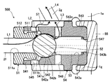
- FIG. 4 is a cross-sectional view showing an enlarged state of the discharge valve mechanism according to the first embodiment of the present invention shown in FIG.
- FIG. 5 is a perspective view showing a disassembled state of the discharge valve mechanism according to the first embodiment of the present invention.
- the discharge valve mechanism 500 includes a discharge valve seat 51, a valve body 52, a discharge valve spring 53, and a discharge valve holder 54.
- the discharge valve seat 51 is integrally provided on one side (left side in FIG. 4) in the axial direction of the tubular seat main body portion 511 whose internal space forms the primary side flow path 511a of the fuel and the diameter. It is composed of an annular flange portion 512 that protrudes outward in the direction.
- the discharge valve seat 51 has a seat surface 511b at the opening edge of the primary side flow path 511a on the other side (right side in FIG. 4) in the axial direction of the seat body 511.
- the seat surface 511b is configured so that the primary side flow path 511a is closed when the valve body 52 is seated.
- the seat surface 511b is a tapered surface that gradually expands in diameter toward the outer side in the axial direction of the primary side flow path 511a. Is formed in.
- the discharge valve sheet 51 is arranged so that the flange portion 512 side faces the pressurizing chamber 3 (discharge flow path 2f) side, and the outer peripheral surface of the flange portion 512 is press-fitted into the inner peripheral surface of the second mounting hole portion 1g. By doing so, it is fixed to the pump body 1a.
- the valve body 52 is arranged on the downstream side of the primary side flow path 511a of the discharge valve seat 51 while being held inside the discharge valve holder 54.
- the valve body 52 is composed of, for example, a ball valve capable of linear contact with the tapered seat surface 511b of the discharge valve seat 51.
- the discharge valve spring 53 is composed of, for example, a coil spring.
- the discharge valve spring 53 is housed inside the discharge valve holder 54 together with the valve body 52, and one end side (left end side in FIG. 4) abuts on the valve body 52 and the other end side (right end side in FIG. 4). ) Is in contact with the bottom portion 543b of the discharge valve holder 54, which will be described later.
- the natural length of the discharge valve spring 53 is set so that the entire valve body 52 and the discharge valve spring 53 can be accommodated in the discharge valve holder 54. As a result, the discharge valve spring 53 and the valve body 52 can be inserted into the discharge valve holder 54 in this order and then assembled, which improves the assemblability of the discharge valve mechanism 500.
- the discharge valve holder 54 is, for example, a bottomed tubular member that opens on one side, and is arranged so that the opening side faces the discharge valve seat 51 side and the bottom side faces the opening side of the second mounting hole portion 1g.
- the discharge valve holder 54 holds a first tubular portion 541 including a portion of the discharge valve seat 51 on the seat surface 511b side of the seat body portion 511 and a valve body 52 inside in this order from the opening side to the bottom side.
- the second tubular portion 542 and the third tubular portion 543 having an internal space forming a spring chamber 543a for accommodating the discharge valve spring 53 and having a bottom portion 543b are integrally formed.
- the end surface of the tip of the first tubular portion 541 is in contact with the end surface of the flange portion 512 of the discharge valve seat 51 on the seat surface 511b side, and the outer peripheral surface of the tip portion is the second mounting hole portion 1g. It is formed so as to be press-fitted into the inner peripheral surface.
- the internal space 541a of the first tubular portion 541 forms a flow path through which the fuel that has passed through the primary side flow path 511a of the discharge valve seat 51 flows in.
- the second tubular portion 542 is formed with a guide portion 542a that guides the movement of the valve body 52 in the direction of contact and separation with respect to the discharge valve seat 51.
- the guide portion 542a is formed of an inner peripheral surface having an inner diameter slightly larger than the outer diameter of the valve body 52, and is continuous with the inner peripheral surface of the first tubular portion 541. That is, the guide portion 542a is formed so as to be slidable with the outer surface of the valve body 52.
- the gap between the guide portion 542a and the outer surface of the valve body 52 is set to a size that functions as a flow throttle that causes a pressure drop of a predetermined value or more when the fluid passes through the gap.
- the guide portion 542a is formed so that the gap between the valve body 52 and the outer surface is equal to or less than a predetermined value obtained by analysis such as simulation or experiment.
- the gap between the guide portion 542a and the valve body 52 (the internal space formed at the position of the guide portion 542a of the second tubular portion 542) is on the downstream side of the internal space 541a (flow path) of the first tubular portion 541. It forms a located flow path.
- a specific example of a settable numerical range in which the gap between the guide portion 542a and the valve body 52 functions as a diaphragm is shown below.
- the following is a case where a ball valve is used as the valve body 52, and the gap is obtained by subtracting the diameter of the valve body 52 from the inner diameter of the guide portion 542a.
- the gap ⁇ 1 assumes a case where the moving speed of the valve body 52 is 1 [m / s].
- the gap ⁇ 1 for obtaining a desired pressure drop is, for example, when the diameter d of the valve body 52 is 4.76 [mm], the gap ⁇ 1 is 1.24 [. mm].
- the tolerance is ⁇ 0.05 [mm]
- the lower limit of the gap ⁇ 1 is 1.19 [mm]
- the upper limit is 1.29 [mm].
- the diameter d is set to 4.76 because it is a standard for the ball diameter that is well distributed in the market, but it is not necessary to limit it to this value.
- the mass of the valve body 52 is proportional to the cube of the diameter d.
- the differential pressure (driving force) acting on the valve body 52 is proportional to the square of the valve body diameter d and inversely proportional to the square of the gap ⁇ 1. Since physical acceleration is a driving force / mass, acceleration of the valve element 52 is proportional to the square root of the diameter d ( ⁇ d), it is inversely proportional to the square of the gap ⁇ 1 ( ⁇ 1 2).
- the diameter d and the gap ⁇ 1 may be selected so that the accelerations are the same. That is, the gap ⁇ 1 is proportional to the square root ( ⁇ d) of the diameter d.
- the range of the gap ⁇ 1 is as follows.
- the larger diameter d of the valve body 52 is assumed to be about 6 [mm].
- the moving speed of the valve body 52 has been described as a specific example of 1 m / s, but it may be slightly larger or smaller depending on the performance and specifications of the pump. Therefore, as a realistic example, the numerical values of the gap ⁇ 2 when the moving speeds are 0.5 m / s and 2 m / s will be described below.
- the acceleration is expected to be quadrupled.
- the gap ⁇ 2 may be halved.
- the gap ⁇ 2 may be doubled.
- the upper and lower limits of the gap ⁇ 2 when the diameter d of the valve body 52 is 3 mm are the following calculated values.
- the upper and lower limits of the gap ⁇ 2 when the diameter d of the valve body 52 is 6 mm are the following calculated values.
- the second tubular portion 542 is also formed with a stopper portion 542b that regulates the movement of the valve body 52 in the lift direction (valve opening direction).
- the stopper portion 542b is formed by an inner peripheral surface located closer to the third tubular portion 543 than the guide portion 542a, and is continuous with the guide portion 542a.
- the inner diameter of the inner peripheral surface of the second tubular portion 542 constituting the stopper portion 542b is smaller than the inner diameter of the guide portion 542a, and the diameter gradually decreases from the guide portion 542a side toward the third tubular portion 543 side. It is composed of tapered surfaces. That is, the stopper portion 542b is formed so as to be in contact with the outer surface of the valve body 52.
- the internal space formed at the position of the stopper portion 542b of the second tubular portion 542 is on the downstream side of the internal space (flow path) formed at the position of the guide portion 542a, and is on the downstream side of the third tubular portion 543.
- a flow path on the upstream side of the spring chamber 543a is formed. That is, the stopper portion 542b is formed at a position between the guide portion 542a and the spring chamber 543a.
- the first tubular portion 541 located closer to the discharge valve seat 51 than the guide portion 542a of the second tubular portion 542 has a plurality of first through holes 545 penetrating in the radial direction (for example, four in FIG. 5). ) Is formed. As shown in FIG. 5, the plurality of first through holes 545 are arranged at intervals in the circumferential direction of the discharge valve holder 54. The first through holes 545 are formed so as to have the same hole diameter, for example.
- the first through hole 545 constitutes a first secondary side flow path that communicates the internal space 541a of the first tubular portion 541 located upstream of the guide portion 542a with the discharge flow path 2g, which is an external flow path. This is to allow fuel to flow out to the side of the valve body 52 in the moving direction (contact / detachment direction) (outward in the radial direction of the discharge valve holder 54).
- a plurality of second through holes 546 penetrating in the radial direction are provided in the third tubular portion 543 located at a position farther from the discharge valve seat 51 than the guide portion 542a and the stopper portion 542b of the second tubular portion 542 (for example,). In FIG. 5, four) are formed. As shown in FIG. 5, for example, the plurality of second through holes 546 are arranged at intervals in the circumferential direction of the discharge valve holder 54, and are arranged in the axial direction with respect to the plurality of first through holes 545. Have been placed. The second through holes 546 are formed so as to have the same hole diameter, for example.
- the second through hole 546 constitutes a second secondary side flow path that allows the spring chamber 543a of the third tubular portion 543 located downstream of the guide portion 542a to communicate with the discharge flow path 2g, which is an external flow path. This is to allow fuel to flow out to the side of the valve body 52 in the moving direction (contact / detachment direction) (outward in the radial direction of the discharge valve holder 54).
- the first through hole 545 and the second through hole 546 can be formed so that, for example, both have the same hole diameter. In this case, it is not necessary to replace the drill for drilling the holes when processing the first through hole 545 and the second through hole 546. It is also possible to set the hole diameter of the first through hole 545 to be equal to or larger than the hole diameter of the second through hole 546. This reflects that the flow rate of the fluid that passes through the guide portion 542a that functions as a diaphragm and flows through the second through hole 546 is relatively smaller than that of the first through hole 545 due to the resistance of the diaphragm. Is.
- the inner surface of the bottom portion 543b of the third tubular portion 543 functions as a receiving seat for the discharge valve spring 53.
- a third through hole 547 that penetrates in the axial direction is formed in the bottom portion 543b of the third tubular portion 543.
- An annular flow path 57 is formed on the radial outer side of the discharge valve holder 54.
- the annular flow path 57 is formed as an outer peripheral surface of the discharge valve holder 54 and an inner peripheral surface of the second mounting hole portion 1g, and is connected to the discharge passage 2g.
- the first through hole 545 and the second through hole 546 of the discharge valve holder 54 are opened in the annular flow path 57.
- the plug 55 is inserted into the second mounting hole portion 1g separately from the discharge valve mechanism 500, and is arranged so as to come into contact with the bottom portion 543b of the discharge valve holder 54. As a result, the plug 55 has a function of preventing the discharge valve holder 54 from coming off.
- thick arrows L1, L2, L3, and L4 indicate fuel flows, respectively.
- the valve body 52 is crimped to the seat surface 511b of the discharge valve seat 51 by the urging force of the discharge valve spring 53, and the valve is closed.
- the fuel pressurized in the compression step of the high-pressure fuel supply pump 1 is introduced into the discharge valve mechanism 500 from the pressurizing chamber 3 (see FIG. 3) through the discharge flow path 2f.
- the gap When fuel passes through the gap between the guide portion 542a of the discharge valve holder 54 and the outer surface of the valve body 52 at the start of valve opening of the valve body 52, the gap functions as a flow throttle and thus flows into the spring chamber 543a.
- the fuel is in a state where the pressure is lower than that of the fuel in the internal space 541a of the first tubular portion 541.
- a further pressure difference is generated before and after the movement direction of the valve body 52, so that the force acting on the valve body 52 in the lift direction increases.
- the valve opening speed (lift speed) of the valve body 52 increases, so that the valve body 52 can reach a large lift amount in a shorter time. That is, the responsiveness of the valve body 52 when the valve is opened is improved.
- the fuel in the pressurizing chamber 3 smoothly flows out to the discharge valve mechanism side without being hindered, so that it is possible to prevent an excessive pressure rise in the pressurizing chamber 3. it can. Therefore, it is possible to improve the pump efficiency and reduce the load on the member strength.
- the fuel that has flowed into and merged with the annular flow path 57 through the first through hole 545 and the second through hole 546 forms a swirling flow in the annular flow path 57 and then flows out to the discharge flow path 2f.
- the swirling flow in the annular flow path 57 becomes faster than the fuel flowing through the internal space 541a and the spring chamber 543a of the first tubular portion 541, and the pressure drops by that amount.
- the influence of the pressure drop of the annular flow path 57 extends to the spring chamber 543a via the second through hole 546, and the pressure of the spring chamber 543a is further reduced.
- a further pressure difference is generated before and after the movement direction of the valve body 52, so that the responsiveness of the valve body 52 at the time of opening the valve is improved.
- the pressure distribution of the discharge valve mechanism 500 when the valve body 52 is opened is roughly as follows.
- the region where the fuel pressure is the highest is the primary side flow path 511a of the discharge valve seat 51, and the region where the fuel pressure is the highest is the internal space 541a (first tubular portion 541 and the discharge valve) of the first tubular portion 541 of the discharge valve holder 54. It is a space sandwiched between the seat body 511 of the seat 51 and the valve body 52). This is the effect of the pressure loss that occurs when the fuel passes through the gap between the valve body 52 that has been opened and the seat surface 511b of the discharge valve seat 51.
- the region where the fuel pressure is lower than the internal space 541a of the first tubular portion 541 is the spring chamber 543a of the discharge valve holder 54. This is the effect of the pressure drop that occurs when the fuel passes through the gap of the guide portion 542a of the discharge valve holder 54 that functions as a throttle located on the upstream side of the spring chamber 543a.
- the region where the fuel pressure is lower than the spring chamber 543a is the annular flow path 57 located on the downstream side of the first through hole 545 and the second through hole 546 of the discharge valve holder 54. This is because the swirling flow formed in the annular flow path 57 is faster than the flow in the internal space 541a and the spring chamber 543a of the first tubular portion 541, so that the pressure drops.
- the pressure distribution of the discharge valve mechanism 500 when the valve body 52 is opened is as follows: the primary side flow path 511a of the discharge valve seat 51, the internal space 541a of the first tubular portion 541 of the discharge valve holder 54, and the spring chamber 543a. , The annular flow path 57 decreases in this order.
- the discharge valve mechanism 500 has a discharge valve seat (valve seat portion) 51 having a primary side flow path 511a and a discharge valve seat (valve seat portion) 51.
- a valve body 52 that can be seated and released and a guide that is formed so as to be slidable on the outer surface of the valve body 52 and guides the movement of the valve body 52 in the contact / separation direction with respect to the discharge valve seat (valve seat portion) 51. It includes a portion 542a.
- the guide portion 542a includes a portion set so that the gap between the valve body 52 and the outer surface thereof is equal to or less than a predetermined value.
- the first through hole 545 as the first secondary side flow path for communicating the internal space 541a on the upstream side of the guide portion 542a with the discharge flow path (external flow path) 2g is lateral to the moving direction of the valve body 52. It is formed so as to allow the fluid to flow out, and also serves as a second secondary side flow path for communicating the spring chamber (internal space) 543a on the downstream side of the guide portion 542a with the discharge flow path (external flow path) 2g.
- the second through hole 546 is formed so as to allow the fluid to flow out to the side of the valve body 52 in the moving direction.
- the guide portion 542a functions as a flow throttle to cause a pressure drop of the fluid. Therefore, the internal space before and after the valve body 52 in the moving direction (internal space 541a on the upstream side of the guide portion 542a) is correspondingly large. And the fluid differential pressure in the internal space 543a) on the downstream side further increases. Therefore, since the valve opening operation of the valve body 52 becomes faster due to the increased fluid differential pressure, the responsiveness of the discharge valve mechanism 500 at the time of valve opening can be improved.
- the discharge valve mechanism 500 is further provided with a stopper portion 542b which is formed so as to come into contact with the outer surface of the valve body 52 and regulates the movement of the valve body 52 in the lift direction.
- a stopper portion 542b which is formed so as to come into contact with the outer surface of the valve body 52 and regulates the movement of the valve body 52 in the lift direction.
- the stopper portion 542b is formed at a position between the guide portion 542a and the second through hole (second secondary side flow path) 546. According to this configuration, by avoiding the stopper portion 542b as the forming position of the second through hole 546, it is possible to reduce the labor of manufacturing the second through hole 546. For example, when the stopper portion 542b is formed in a tapered shape, if the second through hole 546 is formed at the position of the stopper portion 542b, burrs are likely to occur when the second through hole 546 is manufactured. In this case, the deburring process is troublesome.
- the discharge valve mechanism 500 includes a tubular discharge valve holder (valve holder) 54 in which the valve body 52 is held inside and the guide portion 542a is formed. According to this configuration, since the discharge valve holder 54 also serves as a guide for the valve body 52, the discharge valve mechanism 500 can be simply configured.
- the discharge valve holder (valve holder) 54 is located at a position where the first secondary side flow path is closer to the discharge valve seat (valve seat portion) 51 than the guide portion 542a.
- the discharge valve holder (valve holder) is configured by a first through hole 545 that penetrates in the radial direction, and the second secondary side flow path is located farther from the discharge valve seat (valve seat portion) 51 than the guide portion 542a. It is composed of a second through hole 546 that penetrates 54 in the radial direction. According to this configuration, since the first through hole 545 and the second through hole 546 are formed in one discharge valve holder 54, the discharge valve mechanism 500 can be simply configured.
- annular flow path 57 is formed on the radial outer side of the discharge valve holder (valve holder) 54, and the first through hole 545 and the second through hole 546 are annular, respectively. It is open to the flow path 57.
- the fuel flowing into the annular flow path 57 through the first through hole 545 and the second through hole 546 forms a swirling flow, which is faster than the internal flow of the discharge valve holder (valve holder) 54. Therefore, a pressure drop occurs in the annular flow path 57 by that amount.
- a plurality of first through holes 545 are formed in the circumferential direction of the discharge valve holder (valve holder) 54, and the hole diameters of the first through holes 545 are all the same. According to this configuration, it is not necessary to replace the drill when machining the first through hole 545, and the first through hole 545 can be easily manufactured.
- a plurality of second through holes 546 are formed in the circumferential direction of the discharge valve holder (valve holder) 54, and the hole diameters of the second through holes 546 are all the same. According to this configuration, it is not necessary to replace the drill when machining the second through hole 546, and the second through hole 546 can be easily manufactured.
- the first through hole 545 and the second through hole 546 are formed so that the hole diameters of both are the same. According to this configuration, it is not necessary to replace the drill when machining the first through hole 545 and the second through hole 546, and it is possible to suppress an increase in man-hours in both steps of the first through hole 545 and the second through hole 546. it can.
- the discharge valve mechanism 500 it is possible to set the hole diameter of the first through hole 545 to be equal to or larger than the hole diameter of the second through hole 546. According to this configuration, by setting the hole diameter according to the flow rate ratio flowing through the first through hole 545 and the second through hole 546, excessive pressure is applied to the fuel passing through the first through hole 545 and the second through hole 546. It is possible to avoid the loss and to discharge the fuel in the high pressure state.
- the high-pressure fuel supply pump 1 includes the discharge valve mechanism 500 described above, it is possible to obtain the discharge valve mechanism 500 having improved responsiveness at the time of valve opening.
- FIG. 6 is a cross-sectional view of the discharge valve mechanism according to the second embodiment of the present invention cut in a plane including the first through hole.
- FIG. 7 is a cross-sectional view of the discharge valve mechanism according to the second embodiment of the present invention cut in a plane including a second through hole different from the cut surface shown in FIG.
- FIG. 8 is a perspective view showing a discharge valve holder constituting a part of the discharge valve mechanism according to the second embodiment of the present invention.
- those having the same reference numerals as those shown in FIGS. 1 to 5 have the same parts, and thus detailed description thereof will be omitted.
- the discharge valve mechanism 500A according to the second embodiment of the present invention shown in FIGS. 6 and 7 is different from the discharge valve mechanism 500 (see FIGS. 4 and 5) according to the first embodiment.
- the structures of the discharge valve seat 51A and the discharge valve holder 54A are different.
- the positions and relative arrangements of the first through hole 545A (shown only in FIG. 6) and the second through hole (shown only in FIG. 7) provided in the discharge valve holder 54A are different.
- the discharge valve seat 51A has a tubular seat body 511 whose internal space forms a primary side flow path 511a for fuel and one side in the axial direction of the seat body 511 (in FIGS. 6 and 7). It is composed of an annular flange portion 512A that is integrally provided on the right side) and projects outward in the radial direction.
- the discharge valve seat 51A has a seat surface 511b at the opening edge of the primary side flow path 511a on the flange portion 512A side of the seat body portion 511.
- the discharge valve seat 51A is arranged so that the flange portion 512A side faces the valve body 52 side, and the outer peripheral surface of the seat body portion 511 on the tip end side is on the inner peripheral surface of the discharge flow path 2f on the pressurizing chamber 3 side. It is fixed to the pump body 1a by being press-fitted.
- the discharge valve holder 54A has a valve body in which a first tubular portion 541A, a guide portion 542a, and a stopper portion 542b are formed in order from the opening side to the bottom side in contact with the end surface of the flange portion 512A of the discharge valve sheet 51A.
- a bottomed first embodiment having a second tubular portion 542 having a structure similar to that of the first embodiment, which holds the 52 inside, and a spring chamber 543a and a ridge portion 543c having a structure similar to that of the first embodiment.
- the three tubular portions 543 are integrally formed and configured.
- the inner diameter of the first tubular portion 541A (the portion of the second tubular portion 542 facing the discharge valve seat 51A side from the guide portion 542a side) is from the guide portion 542a side toward the discharge valve seat 51A side (to the tip side). It has an inner diameter expanding portion (inner peripheral surface) 541b formed so as to gradually expand the diameter (toward).
- the inner diameter expanding portion 541b forms an internal space 541a and is continuous with the guide portion 542a.
- the first through hole 545A is formed at a position from a portion of the first tubular portion 541A near the second tubular portion 542 to a part of the guide portion 542a of the second tubular portion 542. ing. That is, the first through hole 545A is opened in a part of the inner diameter expanding portion 541b of the first tubular portion 541A and a part of the guide portion 542a of the second tubular portion 542.
- the first through hole 545A is a first through hole 545A that allows the internal space 541a of the first tubular portion 541 located upstream of the guide portion 542a and the internal space formed at the position of the guide portion 542a to communicate with the discharge flow path 2g. It constitutes a secondary side flow path, and allows fuel to flow out to the side of the valve body 52 in the moving direction (outward in the radial direction of the discharge valve holder 54A).
- the second through hole 546A is formed at the position of the stopper portion 542b in the second tubular portion 542. That is, the second through hole 546A penetrates the discharge valve holder 54A in the radial direction at a position farther from the discharge valve seat 51A than the first through hole 545A, and opens in the stopper portion 542b of the second tubular portion 542. ..
- the second through hole 546A constitutes a second secondary side flow path for communicating the internal space formed at the position of the stopper portion 542b on the downstream side of the guide portion 542a with the discharge flow path 2g, and is a valve.
- the fuel flows out to the side of the body 52 in the moving direction (outward in the radial direction of the discharge valve holder 54A).
- a plurality of first through holes 545A are formed (four in FIG. 8) at intervals in the circumferential direction of the discharge valve holder 54A.
- the first through holes 545A are formed so as to have the same hole diameter, for example.
- a plurality of second through holes 546A (four in FIG. 8) are formed at intervals in the circumferential direction of the discharge valve holder 54A.
- the second through holes 546A are formed so as to have the same hole diameter, for example.
- the plurality of first through holes 545A and second through holes 546A are arranged so that their positions in the circumferential direction are staggered (in FIG. 8, they are displaced by 45 ° from each other), and the positions in the axial direction are first. It is arranged at a closer position than in the case of the embodiment of.
- the length of the discharge valve holder 54A having such a configuration can be made shorter than that of the discharge valve holder 54 of the first embodiment.
- FIGS. 6 and 7 thick arrows L1, L2, L3, and L4 indicate fuel flow, respectively.
- valve opening speed (lift speed) of the valve body 52 increases, so that the responsiveness of the valve body 52 at the time of valve opening is improved.
- the effect of narrowing the flow due to the gap between the guide portion 542a and the outer surface of the valve body 52 is the first effect. It is smaller than the case of the embodiment. That is, the pressure drop of the fuel that has passed through the gap becomes smaller, and the fuel differential pressure becomes smaller before and after the movement direction of the valve body 52.
- the plurality of first through holes 545A and the second through holes 546A are arranged so as to be staggered in the circumferential direction. Therefore, as shown in FIG. 7, the first through hole 545A is not arranged in the middle of the flow (see L3) from the gap between the guide portion 542a and the outer surface of the valve body 52 toward the second through hole 546A at the shortest distance. Therefore, it is possible to suppress a decrease in the effect of narrowing the flow due to the gap.
- the diameter of the first tubular portion 541A of the discharge valve holder 54A is gradually increased from the guide portion 542a side toward the discharge valve seat 51A side.
- the inner diameter enlarged portion 541b is formed.
- the pressure in the internal space 541a of the first tubular portion 541 increases. Therefore, since a further pressure difference is generated before and after the movement direction of the valve body 52, the force acting on the valve body 52 in the lift direction increases. As a result, the valve opening speed (lift speed) of the valve body 52 increases, so that the responsiveness of the valve body 52 at the time of valve opening is improved.
- the fuel that has flowed into and merged with the annular flow path 57 through the first through hole 545A and the second through hole 546A forms a high-speed swirling flow in the annular flow path 57 as in the first embodiment. Since it is formed, a pressure drop occurs accordingly. At this time, since the influence of the pressure drop of the annular flow path 57 extends to the spring chamber 543a via the second through hole 546A, the pressure of the spring chamber 543a is also further reduced. As a result, a further pressure difference is generated before and after the movement direction of the valve body 52, so that the force acting on the valve body 52 in the lift direction increases. As a result, the valve opening speed (lift speed) of the valve body 52 increases, so that the responsiveness of the valve body 52 at the time of valve opening is improved.
- the discharge valve mechanism 500A includes a discharge valve seat (valve seat portion) 51A having a primary side flow path 511a and a discharge valve seat (valve seat portion) 51A.
- a valve body 52 that can be seated and released and a guide that is formed so as to be slidable on the outer surface of the valve body 52 and guides the movement of the valve body 52 in the contact / separation direction with respect to the discharge valve seat (valve seat portion) 51A. It includes a portion 542a.
- the guide portion 542a includes a portion set so that the gap between the valve body 52 and the outer surface thereof is equal to or less than a predetermined value.
- the second through hole 546A as the secondary side flow path is formed so as to allow the fluid to flow out to the side in the moving direction of the valve body 52.
- the guide portion 542a functions as a flow throttle to cause a pressure drop of the fluid. Therefore, the internal space before and after the valve body 52 in the moving direction (internal space 541a on the upstream side of the guide portion 542a) is correspondingly large. And the fluid differential pressure in the internal space 543a) on the downstream side further increases. Therefore, since the valve opening operation of the valve body 52 becomes faster due to the increased fluid differential pressure, the responsiveness of the discharge valve mechanism 500A at the time of valve opening can be improved.
- the discharge valve mechanism 500A further includes a stopper portion 542b formed so as to be in contact with the outer surface of the valve body 52 and restricting the movement of the valve body 52 in the lift direction, and the stopper portion 542b is a guide.
- the internal space formed on the downstream side of the portion 542b and formed at the position of the stopper portion 542b by the second through hole 546A (second secondary side flow path) is communicated with the discharge flow path (external flow path) 2g. Is formed in.
- the axial positions of the first through hole 545A and the second through hole 546A are closer than those in the first embodiment, so that the axial length of the discharge valve holder 54A can be shortened. It is possible.
- a tubular discharge valve holder (valve holder) 54A for holding the valve body 52 inside is provided, and the first secondary side flow path is the discharge valve holder (valve holder).
- Valve holder) 54A is composed of a first through hole 545A penetrating in the radial direction, and the second secondary flow path is discharged at a position farther from the discharge valve seat (valve seat portion) 51A side than the first through hole 545A.
- first through hole 545A and the second through hole 546A are spaced apart from each other in the circumferential direction of the discharge valve holder (valve holder) 54A.
- the first through hole 545A and the second through hole 546A are arranged so that their positions in the circumferential direction do not overlap with each other. According to this configuration, since the first through hole 545A is not arranged in the middle of the flow (see L3) from the gap between the guide portion 542a and the outer surface of the valve body 52 toward the second through hole 546A, the flow due to the gap. It is possible to suppress a decrease in the effect of squeezing.
- the discharge valve mechanism 500A includes a cylindrical discharge valve holder (valve holder) 54A in which the valve body 52 is held inside and the guide portion 542a is formed, and the discharge valve holder (valve) is provided.
- the inner diameter of the portion (first tubular portion 541) of the holder) 54A from the guide portion 542a side toward the discharge valve seat (valve seat portion) 51A side gradually increases toward the discharge valve seat (valve seat portion) 51A side.
- a part of the first through hole (first secondary side flow path) 545A is provided on the inner peripheral surface of the inner diameter expanding portion 541b of the discharge valve holder (valve holder) 54A. It is open.
- the fuel flowing into the internal space 541a formed by the inner diameter expanding portion 541b on the upstream side of the guide portion 542a is caused by the shape of the inner diameter expanding portion 541b whose diameter is reduced with respect to the direction of the fuel flow. Since a part of the fuel stagnates in the internal space 541a, the flow velocity is greatly reduced, and the pressure is increased by that amount. Therefore, since a further pressure difference is generated before and after the movement direction of the valve body 52, the responsiveness at the time of opening the valve body 52 can be improved.
- the present invention is not limited to the above-described embodiment, and includes various modifications.
- the above-described embodiments have been described in detail in order to explain the present invention in an easy-to-understand manner, and are not necessarily limited to those having all the described configurations. It is possible to replace a part of the configuration of one embodiment with the configuration of another embodiment, and it is also possible to add the configuration of another embodiment to the configuration of one embodiment. It is also possible to add, delete, or replace a part of the configuration of each embodiment with another configuration.
- the discharge valve mechanism 500 includes the discharge valve spring 53
- the discharge valve mechanism may be configured by omitting the discharge valve spring 53.
- the discharge valve mechanism 500 having a configuration including the discharge valve spring 53 can obtain more stable valve body operation.
- the hole diameters of the first through hole 545 and the second through hole 546 are configured to be the same, but the hole diameters of the first through hole 545 and the second through hole 546 are the same. , It can be changed as appropriate according to the pump flow rate. Further, the number of the first through hole 545 and the second through hole 546 provided in the discharge valve holder 54 and the positions in the circumferential direction can be appropriately changed according to the pump flow rate.
- the solenoid suction valve mechanism 300 is composed of a normally open type solenoid valve.
- the suction valve mechanism is a solenoid valve that can be opened and closed electromagnetically, the effect on the low pressure portion of the high pressure fuel supply pump is substantially the same, and there is no effect on the application of the discharge valve structure of the present application.
Landscapes
- Engineering & Computer Science (AREA)
- Chemical & Material Sciences (AREA)
- Combustion & Propulsion (AREA)
- Mechanical Engineering (AREA)
- General Engineering & Computer Science (AREA)
- Fuel-Injection Apparatus (AREA)
Priority Applications (4)
| Application Number | Priority Date | Filing Date | Title |
|---|---|---|---|
| JP2021569782A JP7273196B2 (ja) | 2020-01-07 | 2020-12-11 | 吐出弁機構及びそれを備えた高圧燃料供給ポンプ |
| DE112020005427.6T DE112020005427T5 (de) | 2020-01-07 | 2020-12-11 | Auslassventilmechanismus und Hochdruck-Kraftstoffzufuhrpumpe, die ihn enthält |
| US17/784,560 US11781513B2 (en) | 2020-01-07 | 2020-12-11 | Discharge valve mechanism and high-pressure fuel supply pump including the same |
| CN202080084933.7A CN114787497B (zh) | 2020-01-07 | 2020-12-11 | 排出阀机构及具备该排出阀机构的高压燃料供给泵 |
Applications Claiming Priority (2)
| Application Number | Priority Date | Filing Date | Title |
|---|---|---|---|
| JP2020-001045 | 2020-01-07 | ||
| JP2020001045 | 2020-01-07 |
Publications (1)
| Publication Number | Publication Date |
|---|---|
| WO2021140829A1 true WO2021140829A1 (ja) | 2021-07-15 |
Family
ID=76788702
Family Applications (1)
| Application Number | Title | Priority Date | Filing Date |
|---|---|---|---|
| PCT/JP2020/046235 Ceased WO2021140829A1 (ja) | 2020-01-07 | 2020-12-11 | 吐出弁機構及びそれを備えた高圧燃料供給ポンプ |
Country Status (5)
| Country | Link |
|---|---|
| US (1) | US11781513B2 (https=) |
| JP (1) | JP7273196B2 (https=) |
| CN (1) | CN114787497B (https=) |
| DE (1) | DE112020005427T5 (https=) |
| WO (1) | WO2021140829A1 (https=) |
Cited By (1)
| Publication number | Priority date | Publication date | Assignee | Title |
|---|---|---|---|---|
| US20230029119A1 (en) * | 2020-01-07 | 2023-01-26 | Hitachi Astemo, Ltd. | Discharge valve mechanism and high-pressure fuel supply pump including the same |
Families Citing this family (2)
| Publication number | Priority date | Publication date | Assignee | Title |
|---|---|---|---|---|
| JP7504773B2 (ja) * | 2020-11-06 | 2024-06-24 | 日立Astemo株式会社 | 信号伝送装置、信号伝送システム、情報提供方法 |
| US12460612B2 (en) * | 2021-09-03 | 2025-11-04 | Hitachi Astemo, Ltd. | Fuel pump |
Citations (5)
| Publication number | Priority date | Publication date | Assignee | Title |
|---|---|---|---|---|
| DE102014212646A1 (de) * | 2014-04-15 | 2015-10-15 | Robert Bosch Gmbh | Kraftstoff-Hochdruckpumpe, mit einem Auslassventil mit einem Ventilkörper und einer Ventilkugel |
| WO2015163246A1 (ja) * | 2014-04-25 | 2015-10-29 | 日立オートモティブシステムズ株式会社 | 高圧燃料供給ポンプ |
| CN205446004U (zh) * | 2015-12-23 | 2016-08-10 | 飞思途(天津)科技发展有限公司 | 一种高压柱塞泵泵阀 |
| WO2019012970A1 (ja) * | 2017-07-14 | 2019-01-17 | 日立オートモティブシステムズ株式会社 | 高圧燃料ポンプ |
| JP2019031977A (ja) * | 2014-12-18 | 2019-02-28 | 日立オートモティブシステムズ株式会社 | 高圧燃料供給ポンプ |
Family Cites Families (24)
| Publication number | Priority date | Publication date | Assignee | Title |
|---|---|---|---|---|
| US3894556A (en) * | 1974-01-02 | 1975-07-15 | Lear Siegler Inc | Pressure limiting valve |
| US4706705A (en) * | 1986-04-01 | 1987-11-17 | The Lee Company | Check valve |
| DE68916267T2 (de) * | 1988-01-18 | 1994-10-13 | Diesel Kiki Co., Ltd., Tokio/Tokyo | Druckausgleichsventil. |
| US8397749B2 (en) * | 2007-09-07 | 2013-03-19 | Metaldyne Company Llc | Piston cooling jet with tracking ball orifice |
| JP4413260B2 (ja) * | 2007-10-12 | 2010-02-10 | 株式会社日本自動車部品総合研究所 | 高圧燃料ポンプ |
| JP4650851B2 (ja) * | 2008-07-03 | 2011-03-16 | 三菱電機株式会社 | 燃料圧力調整装置及びそれを備える燃料供給装置 |
| JP2010116979A (ja) * | 2008-11-13 | 2010-05-27 | Advics Co Ltd | 逆流防止装置 |
| JP5180365B2 (ja) * | 2009-02-20 | 2013-04-10 | 日立オートモティブシステムズ株式会社 | 高圧燃料供給ポンプ及びそれに用いる吐出弁ユニット |
| JP2012184820A (ja) * | 2011-03-07 | 2012-09-27 | Mikuni Corp | 流体通路を内部に備えたハウジングへのチェックバルブの取付け手段 |
| DE102011101258A1 (de) * | 2011-05-11 | 2012-11-15 | Voss Automotive Gmbh | "Druckbegrenzungsventil" |
| JP2013133753A (ja) * | 2011-12-27 | 2013-07-08 | Bosch Corp | 圧力調整弁 |
| DE102013215275A1 (de) * | 2013-08-02 | 2015-02-05 | Robert Bosch Gmbh | Kraftstoffhochdruckpumpe, mit einem Auslassventil |
| DE102014207194A1 (de) * | 2014-04-15 | 2015-10-15 | Robert Bosch Gmbh | Kraftstoff-Hochdruckpumpe, mit einem Auslassventil mit einer Ventilkugel und einem Ventilkörper |
| WO2018003415A1 (ja) * | 2016-06-27 | 2018-01-04 | 日立オートモティブシステムズ株式会社 | 高圧燃料供給ポンプ |
| JP6897173B2 (ja) * | 2017-03-07 | 2021-06-30 | 株式会社デンソー | 高圧ポンプ |
| GB2570648B (en) * | 2018-01-26 | 2020-10-14 | Delphi Tech Ip Ltd | Fuel Pump |
| GB2571933A (en) * | 2018-03-12 | 2019-09-18 | Delphi Automotive Systems Lux | Outlet metering valve for high pressure fuel pump |
| US10808667B2 (en) * | 2018-09-27 | 2020-10-20 | Delphi Technologies Ip Limited | Fuel pump and outlet valve thereof |
| JP7163802B2 (ja) * | 2019-02-01 | 2022-11-01 | トヨタ自動車株式会社 | 逆止弁 |
| US11015558B2 (en) * | 2019-02-15 | 2021-05-25 | Delphi Technologies Ip Limited | Combination outlet valve and pressure relief valve and fuel pump using the same |
| DE112020004456B4 (de) * | 2019-11-13 | 2024-03-14 | Hitachi Astemo, Ltd. | Kraftstoffzufuhrpumpe |
| WO2021140829A1 (ja) * | 2020-01-07 | 2021-07-15 | 日立Astemo株式会社 | 吐出弁機構及びそれを備えた高圧燃料供給ポンプ |
| US11280304B1 (en) * | 2020-11-16 | 2022-03-22 | Delphi Technologies Ip Limited | Fuel pressure regulator |
| US11352994B1 (en) * | 2021-01-12 | 2022-06-07 | Delphi Technologies Ip Limited | Fuel pump and combination outlet and pressure relief valve thereof |
-
2020
- 2020-12-11 WO PCT/JP2020/046235 patent/WO2021140829A1/ja not_active Ceased
- 2020-12-11 JP JP2021569782A patent/JP7273196B2/ja active Active
- 2020-12-11 DE DE112020005427.6T patent/DE112020005427T5/de active Pending
- 2020-12-11 CN CN202080084933.7A patent/CN114787497B/zh active Active
- 2020-12-11 US US17/784,560 patent/US11781513B2/en active Active
Patent Citations (5)
| Publication number | Priority date | Publication date | Assignee | Title |
|---|---|---|---|---|
| DE102014212646A1 (de) * | 2014-04-15 | 2015-10-15 | Robert Bosch Gmbh | Kraftstoff-Hochdruckpumpe, mit einem Auslassventil mit einem Ventilkörper und einer Ventilkugel |
| WO2015163246A1 (ja) * | 2014-04-25 | 2015-10-29 | 日立オートモティブシステムズ株式会社 | 高圧燃料供給ポンプ |
| JP2019031977A (ja) * | 2014-12-18 | 2019-02-28 | 日立オートモティブシステムズ株式会社 | 高圧燃料供給ポンプ |
| CN205446004U (zh) * | 2015-12-23 | 2016-08-10 | 飞思途(天津)科技发展有限公司 | 一种高压柱塞泵泵阀 |
| WO2019012970A1 (ja) * | 2017-07-14 | 2019-01-17 | 日立オートモティブシステムズ株式会社 | 高圧燃料ポンプ |
Cited By (2)
| Publication number | Priority date | Publication date | Assignee | Title |
|---|---|---|---|---|
| US20230029119A1 (en) * | 2020-01-07 | 2023-01-26 | Hitachi Astemo, Ltd. | Discharge valve mechanism and high-pressure fuel supply pump including the same |
| US11781513B2 (en) * | 2020-01-07 | 2023-10-10 | Hitachi Astemo, Ltd. | Discharge valve mechanism and high-pressure fuel supply pump including the same |
Also Published As
| Publication number | Publication date |
|---|---|
| CN114787497A (zh) | 2022-07-22 |
| JP7273196B2 (ja) | 2023-05-12 |
| JPWO2021140829A1 (https=) | 2021-07-15 |
| US11781513B2 (en) | 2023-10-10 |
| CN114787497B (zh) | 2023-11-24 |
| US20230029119A1 (en) | 2023-01-26 |
| DE112020005427T5 (de) | 2022-08-25 |
Similar Documents
| Publication | Publication Date | Title |
|---|---|---|
| CN104093969B (zh) | 具备电磁驱动型的吸入阀的高压燃料供给泵 | |
| WO2011108131A1 (ja) | 電磁式の流量制御弁及びそれを用いた高圧燃料供給ポンプ | |
| WO2021140829A1 (ja) | 吐出弁機構及びそれを備えた高圧燃料供給ポンプ | |
| JP6308921B2 (ja) | 高圧燃料供給ポンプ | |
| JP7198363B2 (ja) | 電磁吸入弁及び高圧燃料供給ポンプ | |
| CN110832188B (zh) | 高压燃料泵 | |
| JP2014105669A (ja) | 高圧燃料供給ポンプ | |
| US12085074B2 (en) | Electromagnetic valve mechanism and high-pressure fuel supply pump | |
| JP5211182B2 (ja) | 高圧ポンプ | |
| JP6649483B2 (ja) | 高圧燃料供給ポンプ | |
| JP2021188544A (ja) | 燃料ポンプ | |
| JP2019090365A (ja) | 燃料供給ポンプ | |
| JP2020133490A (ja) | 高圧燃料供給ポンプ及びリリーフ弁機構 | |
| WO2022091554A1 (ja) | 燃料ポンプ | |
| JP2019167897A (ja) | 燃料供給ポンプ | |
| JP7644684B2 (ja) | 燃料ポンプ | |
| JP7385750B2 (ja) | 燃料ポンプ | |
| JP6689153B2 (ja) | 燃料供給ポンプ | |
| CN113692487B (zh) | 高压燃料泵 | |
| WO2021229862A1 (ja) | 弁機構及びそれを備えた高圧燃料供給ポンプ | |
| JP2019203437A (ja) | 高圧燃料供給ポンプ | |
| WO2024084567A1 (ja) | 燃料ポンプ | |
| WO2025197059A1 (ja) | 燃料ポンプ | |
| WO2023062684A1 (ja) | 電磁吸入弁及び燃料供給ポンプ | |
| JP2021148043A (ja) | 燃料ポンプ |
Legal Events
| Date | Code | Title | Description |
|---|---|---|---|
| 121 | Ep: the epo has been informed by wipo that ep was designated in this application |
Ref document number: 20912480 Country of ref document: EP Kind code of ref document: A1 |
|
| ENP | Entry into the national phase |
Ref document number: 2021569782 Country of ref document: JP Kind code of ref document: A |
|
| 122 | Ep: pct application non-entry in european phase |
Ref document number: 20912480 Country of ref document: EP Kind code of ref document: A1 |