WO2021140598A1 - 変位拡大機構、アクチュエータ、研磨装置、電子部品処理装置、ディスペンサ、およびエアバルブ - Google Patents
変位拡大機構、アクチュエータ、研磨装置、電子部品処理装置、ディスペンサ、およびエアバルブ Download PDFInfo
- Publication number
- WO2021140598A1 WO2021140598A1 PCT/JP2020/000358 JP2020000358W WO2021140598A1 WO 2021140598 A1 WO2021140598 A1 WO 2021140598A1 JP 2020000358 W JP2020000358 W JP 2020000358W WO 2021140598 A1 WO2021140598 A1 WO 2021140598A1
- Authority
- WO
- WIPO (PCT)
- Prior art keywords
- longitudinal direction
- piezoelectric element
- displacement
- support member
- electronic component
- Prior art date
- Legal status (The legal status is an assumption and is not a legal conclusion. Google has not performed a legal analysis and makes no representation as to the accuracy of the status listed.)
- Ceased
Links
Images









Classifications
-
- H—ELECTRICITY
- H02—GENERATION; CONVERSION OR DISTRIBUTION OF ELECTRIC POWER
- H02N—ELECTRIC MACHINES NOT OTHERWISE PROVIDED FOR
- H02N2/00—Electric machines in general using piezoelectric effect, electrostriction or magnetostriction
- H02N2/02—Electric machines in general using piezoelectric effect, electrostriction or magnetostriction producing linear motion, e.g. actuators; Linear positioners ; Linear motors
- H02N2/04—Constructional details
- H02N2/043—Mechanical transmission means, e.g. for stroke amplification
-
- H—ELECTRICITY
- H02—GENERATION; CONVERSION OR DISTRIBUTION OF ELECTRIC POWER
- H02N—ELECTRIC MACHINES NOT OTHERWISE PROVIDED FOR
- H02N2/00—Electric machines in general using piezoelectric effect, electrostriction or magnetostriction
- H02N2/0005—Electric machines in general using piezoelectric effect, electrostriction or magnetostriction producing non-specific motion; Details common to machines covered by H02N2/02 - H02N2/16
-
- B—PERFORMING OPERATIONS; TRANSPORTING
- B24—GRINDING; POLISHING
- B24B—MACHINES, DEVICES, OR PROCESSES FOR GRINDING OR POLISHING; DRESSING OR CONDITIONING OF ABRADING SURFACES; FEEDING OF GRINDING, POLISHING, OR LAPPING AGENTS
- B24B31/00—Machines or devices designed for polishing or abrading surfaces on work by means of tumbling apparatus or other apparatus in which the work and/or the abrasive material is loose; Accessories therefor
- B24B31/003—Machines or devices designed for polishing or abrading surfaces on work by means of tumbling apparatus or other apparatus in which the work and/or the abrasive material is loose; Accessories therefor whereby the workpieces are mounted on a holder and are immersed in the abrasive material
-
- F—MECHANICAL ENGINEERING; LIGHTING; HEATING; WEAPONS; BLASTING
- F16—ENGINEERING ELEMENTS AND UNITS; GENERAL MEASURES FOR PRODUCING AND MAINTAINING EFFECTIVE FUNCTIONING OF MACHINES OR INSTALLATIONS; THERMAL INSULATION IN GENERAL
- F16K—VALVES; TAPS; COCKS; ACTUATING-FLOATS; DEVICES FOR VENTING OR AERATING
- F16K17/00—Safety valves; Equalising valves, e.g. pressure relief valves
- F16K17/02—Safety valves; Equalising valves, e.g. pressure relief valves opening on surplus pressure on one side; closing on insufficient pressure on one side
-
- F—MECHANICAL ENGINEERING; LIGHTING; HEATING; WEAPONS; BLASTING
- F16—ENGINEERING ELEMENTS AND UNITS; GENERAL MEASURES FOR PRODUCING AND MAINTAINING EFFECTIVE FUNCTIONING OF MACHINES OR INSTALLATIONS; THERMAL INSULATION IN GENERAL
- F16K—VALVES; TAPS; COCKS; ACTUATING-FLOATS; DEVICES FOR VENTING OR AERATING
- F16K31/00—Actuating devices; Operating means; Releasing devices
- F16K31/004—Actuating devices; Operating means; Releasing devices actuated by piezoelectric means
- F16K31/007—Piezoelectric stacks
-
- H—ELECTRICITY
- H02—GENERATION; CONVERSION OR DISTRIBUTION OF ELECTRIC POWER
- H02N—ELECTRIC MACHINES NOT OTHERWISE PROVIDED FOR
- H02N2/00—Electric machines in general using piezoelectric effect, electrostriction or magnetostriction
- H02N2/0005—Electric machines in general using piezoelectric effect, electrostriction or magnetostriction producing non-specific motion; Details common to machines covered by H02N2/02 - H02N2/16
- H02N2/005—Mechanical details, e.g. housings
- H02N2/0055—Supports for driving or driven bodies; Means for pressing driving body against driven body
-
- H—ELECTRICITY
- H02—GENERATION; CONVERSION OR DISTRIBUTION OF ELECTRIC POWER
- H02N—ELECTRIC MACHINES NOT OTHERWISE PROVIDED FOR
- H02N2/00—Electric machines in general using piezoelectric effect, electrostriction or magnetostriction
- H02N2/02—Electric machines in general using piezoelectric effect, electrostriction or magnetostriction producing linear motion, e.g. actuators; Linear positioners ; Linear motors
- H02N2/021—Electric machines in general using piezoelectric effect, electrostriction or magnetostriction producing linear motion, e.g. actuators; Linear positioners ; Linear motors using intermittent driving, e.g. step motors, piezoleg motors
- H02N2/025—Inertial sliding motors
-
- H—ELECTRICITY
- H02—GENERATION; CONVERSION OR DISTRIBUTION OF ELECTRIC POWER
- H02N—ELECTRIC MACHINES NOT OTHERWISE PROVIDED FOR
- H02N2/00—Electric machines in general using piezoelectric effect, electrostriction or magnetostriction
- H02N2/02—Electric machines in general using piezoelectric effect, electrostriction or magnetostriction producing linear motion, e.g. actuators; Linear positioners ; Linear motors
- H02N2/028—Electric machines in general using piezoelectric effect, electrostriction or magnetostriction producing linear motion, e.g. actuators; Linear positioners ; Linear motors along multiple or arbitrary translation directions, e.g. XYZ stages
-
- H—ELECTRICITY
- H02—GENERATION; CONVERSION OR DISTRIBUTION OF ELECTRIC POWER
- H02N—ELECTRIC MACHINES NOT OTHERWISE PROVIDED FOR
- H02N2/00—Electric machines in general using piezoelectric effect, electrostriction or magnetostriction
- H02N2/02—Electric machines in general using piezoelectric effect, electrostriction or magnetostriction producing linear motion, e.g. actuators; Linear positioners ; Linear motors
- H02N2/04—Constructional details
-
- H—ELECTRICITY
- H02—GENERATION; CONVERSION OR DISTRIBUTION OF ELECTRIC POWER
- H02N—ELECTRIC MACHINES NOT OTHERWISE PROVIDED FOR
- H02N2/00—Electric machines in general using piezoelectric effect, electrostriction or magnetostriction
- H02N2/10—Electric machines in general using piezoelectric effect, electrostriction or magnetostriction producing rotary motion, e.g. rotary motors
- H02N2/12—Constructional details
Definitions
- the present invention relates to a displacement expanding mechanism, an actuator, a polishing device, an electronic component processing device, a dispenser, and an air valve.
- a piezoelectric element (piezo element) has existed as an element that generates a required displacement at a relatively low voltage.
- the piezoelectric element is an element having a structure in which a substance having a piezoelectric effect and thin electrodes are alternately stacked, and has a function of converting a force into a voltage or converting a voltage into a force.
- the piezoelectric element can be slightly expanded and contracted by controlling the voltage, it is used in various fields such as an ink injection mechanism of an inkjet printer and a control mechanism such as an actuator.
- the piezoelectric element expands and contracts when a voltage is applied, but since the displacement that occurs is small, a displacement expansion mechanism that expands the displacement of the expanding and contracting piezoelectric element and acts on the object is used.
- Patent Document 1 discloses a displacement expansion mechanism capable of effectively expanding and outputting a displacement amount by displacement of two piezoelectric elements.
- an object of the present invention is to provide a displacement expanding mechanism, a polishing device, an actuator, an electronic component processing device, a dispenser, and an air valve capable of easily controlling a drive system.
- one end is connected to a base portion as a base and a mounting surface of the base portion, and one end portion is attached to the mounting surface alongside the piezoelectric element and a piezoelectric element extending in the first longitudinal direction.
- a support member extending in the second longitudinal direction intersecting the first longitudinal direction is connected to the other end of each of the piezoelectric element and the support member, and as the piezoelectric element expands and contracts, the support member extends in the first longitudinal direction and the second longitudinal direction, respectively. It includes an acting portion that is displaced in different directions of displacement, and a compression member that is connected to each of the base portion and the acting portion and compresses the piezoelectric element in the first longitudinal direction.
- the rigidity of the piezoelectric element in the first longitudinal direction may be less than or equal to the rigidity of the support member in the second longitudinal direction.
- a connecting member for connecting one end portion and the base portion of the piezoelectric element may be provided, and the connecting member may be formed of a material having a higher coefficient of thermal expansion than the support member.
- the connecting member may be formed integrally with the base portion.
- a connecting member for connecting the other end portion of the piezoelectric element and the acting portion may be provided, and the connecting member may be formed of a material having a higher coefficient of thermal expansion than the support member.
- the connecting member may be formed integrally with the working portion.
- the rigidity of the support member in the displacement direction may be less than or equal to the rigidity of the piezoelectric element in the displacement direction.
- the moment of inertia of area around the central axis orthogonal to the displacement direction and passing through the center of the displacement direction of the support member differs depending on the position in the second longitudinal direction. May be good.
- At least one end of the piezoelectric element in the first longitudinal direction and one end of the support member in the second longitudinal direction are provided with hinge members that promote deformation in the displacement direction of the piezoelectric element and the support member. You may.
- At least one of the other end of the piezoelectric element in the first longitudinal direction and the other end of the support member in the second longitudinal direction has a hinge member that promotes deformation of the piezoelectric element and the support member in the displacement direction. It may be provided.
- two compression members may be provided and may be arranged at positions sandwiching the piezoelectric element and the support member.
- the compression member extends in a third longitudinal direction intersecting each of the first longitudinal direction and the second longitudinal direction in a plan view including the first longitudinal direction and the second longitudinal direction, and the compression member has a third longitudinal direction.
- a stretchable portion may be formed in the stretchable portion.
- At least one of the compression members extends in the first longitudinal direction, and the compression member extending in the first longitudinal direction may be formed with a stretchable portion that can expand and contract in the first longitudinal direction.
- one end is connected to the base portion as a base and the mounting surface of the base portion, and one end portion is attached to the mounting surface along with the piezoelectric element and the piezoelectric element extending in the first longitudinal direction.
- a support member extending in the second longitudinal direction intersecting the first longitudinal direction is connected to the other end of each of the piezoelectric element and the support member, and as the piezoelectric element expands and contracts, the support member extends in the first longitudinal direction and the second longitudinal direction, respectively.
- An action part that is displaced in different directions of displacement, a compression member that is connected to each of the base part and the action part and compresses the piezoelectric element in the first longitudinal direction, and a surface to which the piezoelectric element and the support member are attached in the action part. It is provided with a polishing portion provided on the surface opposite to the above.
- one end is connected to the base portion as a base and the mounting surface of the base portion, and one end portion is attached to the mounting surface along with the piezoelectric element and the piezoelectric element extending in the first longitudinal direction.
- the support member extending in the second longitudinal direction intersecting the first longitudinal direction is connected to the other end of each of the piezoelectric element and the support member, and is different from the first longitudinal direction and the second longitudinal direction as the piezoelectric element expands and contracts.
- Piezoelectric by supplying voltage or current to the action part that is displaced in the displacement direction, which is the direction, the compression member that is connected to each of the base part and the action part and compresses the piezoelectric element in the first longitudinal direction, and the piezoelectric element and the support member. It includes a drive unit that expands and contracts the element.
- the actuator of the present invention may drive an actuator used for processing an electronic component in an electronic component device that processes a chip-shaped electronic component.
- the actuator of the present invention is a measuring device for the electronic component processing device to measure the characteristics of the electronic component, and the actuator is a measuring probe for measuring the characteristics in contact with the electronic component. May be good.
- the actuator of the present invention is a measuring device for the electronic component processing device to measure the characteristics of the electronic component
- the actuator is a suction nozzle for sucking the electronic component, and is sucked by the suction nozzle.
- Electronic components may be brought into contact with a measuring probe for measuring properties.
- the actuator of the present invention is an insertion device in which the electronic component processing device inserts the electronic component into the carrier tape when the electronic component is taped, and the actuator is a suction nozzle for sucking the electronic component.
- the electronic component sucked by the suction nozzle may be inserted into the tape.
- the dispenser of the present invention includes a liquid discharge member into which a liquid is introduced and discharges the introduced liquid, a valve for discharging and shutting off the liquid from the liquid discharge member, and the above-mentioned actuator for driving the valve. To be equipped with.
- the air valve of the present invention closes and opens an air pressure chamber into which compressed air is introduced, a valve body having an air discharge port that leads from the air pressure chamber to the outside, and an air discharge port inside the air pressure chamber. It includes a valve body that operates in such a manner and the above-mentioned actuator that is provided in the air pressure chamber and drives the valve body.
- the piezoelectric element and the support member are attached to the base portion, and the action portion is attached to these. Therefore, the piezoelectric element is displaced in the first longitudinal direction, so that the working portion can be displaced in the displacement direction.
- the drive system can be easily controlled as compared with the case where two piezoelectric elements are used.
- the displacement expansion mechanism is provided with a compression member, it is possible to apply a preload in the compression direction to the piezoelectric element. As a result, it is possible to make it difficult for the piezoelectric element, which is easily damaged by the load in the tensile direction, to be loaded in the tensile direction.
- FIG. 4A is a cross-sectional view taken along the line BB
- FIG. 4B is a cross-sectional view taken along the line CC.
- FIG. 1 It is a figure which shows the example of the measuring apparatus for measuring the electronic component using the actuator equipped with the suction nozzle. It is a figure which shows the example of the insertion device which inserts the electronic component which used the actuator equipped with the suction nozzle into a carrier tape. It is sectional drawing which shows the air valve which concerns on one Embodiment. It is a front view of the polishing apparatus which concerns on one Embodiment. It is a partial cross-sectional front view which shows the dispenser which concerns on one Embodiment. It is sectional drawing which shows the state which closed the liquid discharge member of the dispenser of FIG. It is sectional drawing which shows the state which opened the liquid discharge member of the dispenser of FIG.
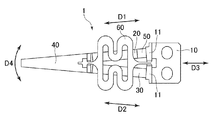
- FIG. 1 is a front view of the displacement expanding mechanism 1 according to the embodiment of the present invention.
- the displacement expanding mechanism 1 is a mechanism using a piezoelectric element 20 that expands the displacement of the piezoelectric element 20 that expands and contracts according to an applied voltage to act on an object.
- the displacement expansion mechanism 1 includes a base portion 10, a piezoelectric element 20, a support member 30, an action portion 40, a connecting member 50, and a compression member 60.
- the base 10 is a portion that serves as a base for the displacement expanding mechanism 1.
- the base 10 is attached to the device.
- a pair of mounting portions 11 for mounting the piezoelectric element 20 and the support member 30 are formed side by side on the base portion 10.
- the base portion 10 may have any shape or material as long as it can be installed in various devices provided with the mounting portion 11 and the displacement expanding mechanism 1.
- the base portion 10 can have a rectangular shape as shown in FIG.
- a metal having a certain rigidity such as stainless steel can be used.
- the piezoelectric element 20 is connected to the mounting surface of the base 10.
- the piezoelectric element 20 is formed in an elongated shape extending in the first longitudinal direction D1.
- the mounting surface of the base 10 is formed on the mounting portion 11.
- the piezoelectric element 20 is a member that expands and contracts according to an applied voltage.
- the piezoelectric element 20 is connected to the mounting portion 11 on one side via a connecting member 50 described later.
- the piezoelectric element 20 can be formed in a rectangular shape, for example, as shown in FIG.
- the piezoelectric element 20 may have a laminated structure in which thin electrodes and thin piezoelectric bodies are alternately stacked. With such a laminated structure, it is possible to realize a large displacement even at a low voltage.
- the piezoelectric element 20 is formed in a rectangular shape in this example, the piezoelectric element 20 is not particularly limited to a rectangular shape, and is not limited to a rectangular shape as long as it can efficiently displace the acting portion 40 by the piezoelectric effect. , Any shape may be used.
- the support member 30 is attached to the attachment surface along with the piezoelectric element 20.
- the support member 30 is formed in an elongated shape extending in the second longitudinal direction D2 which intersects the first longitudinal direction D1 in a plan view.
- the rigidity of the piezoelectric element 20 in the first longitudinal direction D1 is equal to or less than the rigidity of the support member 30 in the second longitudinal direction D2. That is, when the support member 30 is pulled in the second longitudinal direction D2 and the piezoelectric element 20 is pulled in the first longitudinal direction D1, the support member 30 is less likely to be deformed or has the same amount of deformation.
- the support member 30 when the piezoelectric element 20 expands and contracts, the support member 30 also deforms accordingly. Then, the tip of the acting portion 40 is displaced in the displacement direction D4. At this time, the piezoelectric element 20 and the support member 30 are also deformed along the displacement direction D4.
- the rigidity of the displacement direction D4 of the support member 30 is equal to or less than the rigidity of the displacement direction D4 of the piezoelectric element 20.
- the moment of inertia of area around the central axis M that is orthogonal to the displacement direction D4 and passes through the center of the displacement direction D4 of the support member 30 is the second longitudinal moment. It depends on the position of direction D2. This point will be described in detail with reference to FIG.
- FIG. 5 (a) is a cross-sectional view taken along the line BB in FIG. 4, and FIG. 5 (b) is a cross-sectional view taken along the line CC in FIG.
- the cross-sectional shape of the support member 30 differs depending on the position in the second longitudinal direction D2. Comparing the moments of inertia of area around the central axis M in each cross-sectional shape, the moment of inertia of area shown in FIG. 5 (a) is larger than that of the cross-sectional shape shown in FIG. 5 (b). ..
- the support member 30 can secure a degree of freedom in cross-sectional shape as compared with the piezoelectric element 20.
- the action unit 40 is connected to the other end of each of the piezoelectric element 20 and the support member 30.
- the working portion 40 is displaced in the displacement direction D4, which is a direction different from each of the first longitudinal direction D1 and the second longitudinal direction D2, as the piezoelectric element 20 expands and contracts.
- the support member 30 also deforms accordingly.
- the tip of the acting portion 40 is displaced in the displacement direction D4.
- the connecting member 50 connects one end of the piezoelectric element 20 with the mounting portion 11 of the base 10.
- the connecting member 50 is made of a material having a higher coefficient of thermal expansion than the supporting member 30.
- the connecting member 50 may be formed integrally with the mounting portion 11 of the base portion 10.
- the connecting member 50 may not be provided. In this case, one end of the piezoelectric element 20 is directly connected to the mounting portion 11.
- the connecting member 50 may be arranged at the other end of the piezoelectric element 20 instead of one end of the piezoelectric element 20. That is, the connecting member 50 may connect the other end portion of the piezoelectric element 20 and the acting portion 40. In this case, the connecting member 50 may be formed integrally with the working portion 40.
- the compression member 60 is connected to each of the base portion 10 and the acting portion 40, and compresses the piezoelectric element 20 in the first longitudinal direction D1. As shown in FIG. 2, two compression members 60 are provided. The two compression members 60 are arranged at positions sandwiching the piezoelectric element 20 and the support member 30, respectively.
- the compression member 60 extends in the third longitudinal direction D3 intersecting each of the first longitudinal direction D1 and the second longitudinal direction D2 in a plan view.
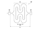
- the compression member 60 is formed with a telescopic portion 61 that can expand and contract in the third longitudinal direction D3.
- the telescopic portion 61 is formed in a bellows shape that extends in the third longitudinal direction D3 in a plan view and is repeatedly curved.
- the structure is curved at three points in the third longitudinal direction, but the structure is not limited to this example, and the shape can be arbitrarily changed.
- the expansion / contraction portion 61 is formed in the intermediate portion of the compression member 60 in the third longitudinal direction D3.
- fixing portions 62 having a large width dimension, which is a dimension in the direction orthogonal to the third longitudinal direction D3, are formed.
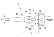
- a fixed slit 70 is formed in each of the acting portion 40 and the base portion 10.
- the compression member 60 is attached to the fixed slit 70. At this time, the compression member 60 is pulled and attached in a slightly stretched state. This content will be described in detail below.
- the dimension L1 of the third longitudinal direction D3 between the two fixing portions 62 shown in FIG. 3 is based on the dimension L2 of the third longitudinal direction D3 of the fixing slits 70 formed in each of the acting portion 40 and the base portion 10 shown in FIG. Is also getting shorter. Therefore, when the compression member 60 is attached to the fixed slit 70 of the action portion 40 and the base portion 10, the compression member 60 is pulled in the third longitudinal direction D3 and attached in a slightly stretched state and elastically deformed. As a result, after the compression member 60 is attached to the fixed slit 70, it is restored and deformed in the third longitudinal direction D3, so that the compressive force from the compression member 60 can be applied to the acting portion 40 and the base portion 10.
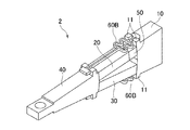
- FIG. 6 is a front view of the displacement expansion mechanism 2 according to the first modification
- FIG. 7 is a perspective view of the displacement expansion mechanism 2 according to the first modification
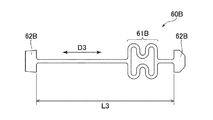
- FIG. 8 is compression in the displacement expansion mechanism 2 according to the first modification.
- the front view and FIG. 9 of the member 60B are side views of the displacement expanding mechanism 2 according to the first modification before mounting the compression member 60B.
- the position where the compression member 60B is attached is different from the displacement expanding mechanism according to the first embodiment. That is, one of the two compression members 60B extends in the first longitudinal direction D1 along the piezoelectric element 20, and the other extends in the second longitudinal direction D2 along the support member 30.
- the compression member 60B extending in the first longitudinal direction D1 is formed with a stretchable portion 61B that can be expanded and contracted in the first longitudinal direction D1.
- fixed portions 62B having a large width dimension, which is a dimension in the direction orthogonal to the first longitudinal direction D1, are formed.
- the dimension L3 of the third longitudinal direction D3 between the two fixing portions 62B shown in FIG. 8 is based on the dimension L4 of the third longitudinal direction D3 of the fixing slits 70 formed in each of the acting portion 40 and the base portion 10 shown in FIG. Is also getting shorter.
- the compression member 60B when the compression member 60B is attached to the fixed slit 70 of the action portion 40 and the base portion 10, the compression member 60B is pulled in the first longitudinal direction D1 and attached in a slightly stretched state and elastically deformed. As a result, after the compression member 60B is attached to the fixed slit 70, it is restored and deformed in the third longitudinal direction D3, so that the compressive force from the compression member 60B is applied to the piezoelectric element 20 via the acting portion 40 and the base portion 10. Can be given.
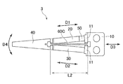
- FIG. 10 is a front view of the displacement expansion mechanism 3 according to the second modification
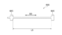
- FIG. 11 is a front view of the compression member 60 in the displacement expansion mechanism 3 according to the second modification.
- the shape of the compression member 60 is different from that of the displacement expanding mechanism according to the first embodiment. That is, the compression member 60 of the displacement expansion mechanism 3 according to this modification is not formed with the expansion / contraction portion 61, and the whole extends straight in the third longitudinal direction D3.
- the dimension L5 of the third longitudinal direction D3 between the two fixing portions 62 shown in FIG. 11 is from the dimension L2 of the third longitudinal direction D3 of the fixing slits 70 formed in each of the acting portion 40 and the base portion 10 shown in FIG. Is also getting shorter.
- the compression member 60 when the compression member 60 is attached to the fixed slit 70 of the action portion 40 and the base portion 10, the compression member 60 is pulled in the first longitudinal direction D1 and attached in a slightly stretched state and elastically deformed. As a result, after the compression member 60 is attached to the fixed slit 70, it is restored and deformed in the third longitudinal direction D3, so that the compressive force from the compression member 60 can be applied to the acting portion 40 and the base portion 10.
- At least one end of the first longitudinal direction D1 of the piezoelectric element 20 and one end of the second longitudinal direction D2 of the support member 30 at least one end of the first longitudinal direction D1 of the piezoelectric element 20 and one end of the second longitudinal direction D2 of the support member 30.
- a hinge member that promotes deformation in the displacement direction D4 may be provided.
- Such a hinge member may be provided at at least one of the other end of the first longitudinal direction D1 of the piezoelectric element 20 and the other end of the second longitudinal direction D2 of the support member 30.
- the piezoelectric element 20 and the support member 30 are attached to the base 10, and the acting portion 40 is attached to these. Therefore, the piezoelectric element 20 is displaced in the first longitudinal direction D1, so that the acting portion 40 can be displaced in the displacement direction D4.
- the drive system can be easily controlled as compared with the case where two piezoelectric elements 20 are used.
- the displacement expanding mechanisms 1 to 3 include the compression member 60, it is possible to apply a preload in the compression direction to the piezoelectric element 20. As a result, it is possible to make it difficult for the piezoelectric element 20 that is easily damaged by the load in the tensile direction to be loaded in the tensile direction.
- the rigidity of the first longitudinal direction D1 of the piezoelectric element 20 is equal to or less than the rigidity of the second longitudinal direction D2 of the support member 30, the energy when the piezoelectric element 20 expands and contracts in the first longitudinal direction D1 is the energy of the support member 30. Loss due to deformation can be suppressed. As a result, the energy efficiency of the displacement expansion mechanisms 1 to 3 can be increased.
- a connecting member 50 for connecting one end portion of the piezoelectric element 20 and the base portion 10 is provided, and the connecting member 50 is made of a material having a higher coefficient of thermal expansion than the support member 30. Therefore, even if the support member 30 causes a larger thermal expansion than the piezoelectric element 20, the connecting member 50 causes a larger thermal expansion than the support member 30 to connect the base portion 10 and the working portion 40. It is necessary to suppress a large difference between the total amount of thermal expansion of the piezoelectric element 20 and the connecting member 50 located on one side of the structure and the amount of thermal expansion of the support member 30 located on the other side. Can be done. As a result, it is possible to suppress a large change in the initial position of the displacement direction D4 of the working portion 40 due to the influence of heat. Further, when the connecting member 50 is integrally formed with the base portion 10, the number of parts can be reduced.
- the connecting member 50 is provided at a position where the other end portion of the piezoelectric element 20 and the acting portion 40 are connected, as described above, the amount of thermal expansion on the piezoelectric element 20 side and the support are provided. It is possible to suppress a large difference from the amount of thermal expansion on the member 30 side.
- the support member 30 is displaced in the displacement direction D4 as the piezoelectric element 20 expands and contracts. Can suppress the limitation of the displacement of the working portion 40 in the displacement direction D4.
- the moment of inertia of area around the central axis M that is orthogonal to the displacement direction D4 and passes through the center of the displacement direction D4 of the support member 30 is the second longitudinal moment. It depends on the position of direction D2. That is, unlike the piezoelectric element 20 formed by, for example, a laminated structure, the degree of freedom can be ensured in the shape of the support member 30. Therefore, it becomes easy to provide the support member 30 with a portion that is easily deformed locally, and the displacement characteristics of the entire displacement expansion mechanisms 1 to 3 can be adjusted by the shape of the support member 30.
- hinges that promote deformation of the displacement direction D4 with respect to the piezoelectric element 20 and the support member 30.
- the piezoelectric element 20 and the support member 30 can be easily deformed in the displacement direction D4 by the hinge member.
- the compression member 60 when the compression member 60 is formed with the expandable and contractible portion 61, the compression member 60 can be easily extended in the third longitudinal direction D3 when the compression member 60 is attached to the base portion 10 and the action portion 40. It becomes possible to do. Thereby, the assembling property of the compression member 60 can be ensured.
- FIG. 12 is a front view showing an example of the actuator 1000 using the displacement expanding mechanism 2 according to the first modification.
- the actuator 1000 is a control machine that is driven by an electric command and performs a predetermined motion.
- the actuator 1000 includes a displacement expanding mechanism 2 and a drive unit 80.
- the drive unit 80 supplies a voltage or current to the piezoelectric element 20 and the support member 30 to expand and contract the piezoelectric element 20.
- FIG. 13 is a front view showing an example in which the actuator of FIG. 12 is used to drive an actuator used for processing an electronic component.
- a measuring probe 1101 which is an actuator, is attached to the tip of the acting portion 40 of the actuator 1000 as an object. The actuator comes into contact with the electronic component on the chip and is used to evaluate the characteristics of the electronic component.
- the drive unit 80 supplies a voltage or current to the piezoelectric element 20 so that the piezoelectric element 20 is displaced by a predetermined amount. As a result, the expanded displacement can be transmitted to the measurement probe 1101 to displace the measurement probe 1101 in the displacement direction D4. Further, the drive unit 80 stops the supply of voltage or current to the piezoelectric element 20. As a result, the measurement probe 1101 can be restored to its original position.
- FIG. 14 is a diagram showing a state in which the electrical characteristics of the electronic component are measured by the measurement probe 1101.
- the turntable 1090 of the measuring device used together with the measuring probe 1101 is rotatably provided and has a plurality of storage grooves 1091 for accommodating the electronic component 1080 along the circumferential direction. Then, while rotating the turntable 1090, the drive unit 80 repeatedly displaces (moves up and down) the measurement probe 1101 as an actuator at high speed, whereby the electrical characteristics of the electronic component 1080 housed in the plurality of storage grooves 1091 and the like. Are sequentially measured.
- the measurement probe 1101 is displaced upward.
- the tip of the measurement probe 1101 is brought into contact with the electrode 1081 provided on the lower surface of the electronic component 1080 to measure the electrical characteristics of the electronic component 1080, and after the measurement, the measurement probe 1101 is displaced downward and retracted. Then, when the next electronic component 1080 reaches the measurement position, the same operation is performed again, and these operations are repeated at high speed.
- the measuring probe which is an actuator
- the measuring probe can be driven at high speed with a practical stroke. Further, it is possible to reduce the damage caused by the tension of the piezoelectric element 20 and the influence of thermal expansion and creep.
- the above has shown an example in which the measuring probe 1101 of the measuring device is used as the actuator, but the actuator is not limited to the measuring probe.
- FIG. 15 is a diagram showing a state in which an actuator 1000 equipped with a suction nozzle 1102 as an actuator is used in an electronic component processing device, and shows a case where the driven actuator is a suction nozzle that sucks electronic components.
- the structure shown in FIG. 15 is the same as the structure shown in FIG. 13 except that the actuator attached to the acting portion 40 of the actuator 1000 replaces the suction nozzle 1102.
- the suction nozzle 1102 is attached to the action unit 40 so as to extend in the vertical direction.
- the suction nozzle 1102 is connected to a suction mechanism (not shown). Then, by sucking by a suction mechanism such as a vacuum pump provided in the suction mechanism, the electronic component is sucked into the suction port 1104 at the lower end of the suction nozzle 1102.
- the actuator 1000 can be used as a measuring device for measuring electronic components.
- An example of the measuring device at that time is shown in FIG.
- This measuring device includes an actuator 1000 (see FIG. 15), a suction nozzle 1102, a suction mechanism, a turntable 1110, a base 1120, and a measuring jig 1130.
- the turntable 1110 is rotatably provided and has a plurality of storage grooves 1111 for storing electronic components 1080 along the circumferential direction.
- the storage groove 1111 is provided so as to penetrate the turntable 1110.
- the electronic component 1080 is housed in the storage groove 1111 so that the electrode 1081 is on the lower surface side.
- the base 1120 rotatably supports the turntable 1110, and its surface serves as a transport surface for electronic components 1080.
- a through hole 1121 is formed in the base 1120, a suction nozzle 1102 as an actuator is provided above the through hole 1121, and a measuring jig 1130 is provided below the through hole 1121.
- the measuring jig 1130 is attached to the gantry 1140, and a measuring terminal 1131 is provided on the upper surface of the measuring jig 1130 at a position corresponding to the electrode 1081 of the electronic component 1080.
- the turntable 1110 is rotated to transport the electronic component 1080 stored in the storage groove 1111 along the transport surface of the base 1120, and when the position corresponding to the through hole 1121 is reached, the electronic component 1080 is attracted. It is attracted to the nozzle 1102. Then, in this state, the suction nozzle 1102 is displaced downward to bring the electrode 1081 of the electronic component 1080 into contact with the measurement terminal 1131 of the measuring jig 1130, and the electrical characteristics of the electronic component 1080 are measured.
- the suction nozzle 1102 is displaced upward, and the electronic component 1080 sucked by the suction nozzle 1102 is returned to the transport surface to release the suction. Then, when the next electronic component 1080 reaches the position corresponding to the through hole 1121, the same operation is performed again, and these operations are repeated at high speed.
- the actuator 1000 equipped with the suction nozzle 1102 can also be used as an insertion device for charging electronic components into the carrier tape.
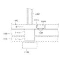
- An example of the insertion device at that time is shown in FIG.
- This insertion device includes an actuator 1000 (see FIG. 15), a suction nozzle 1102, a suction mechanism, a turntable 1150, a base 1160, and a magnet 1180.
- the turntable 1150 is rotatably provided and has a plurality of storage grooves 1151 for storing electronic components 1080 along the circumferential direction.
- the storage groove 1151 is provided so as to penetrate the turntable 1150.
- the base 1160 rotatably supports the turntable 1150, and its surface serves as a transport surface for electronic components 1080.
- a carrier tape 1170 is movably arranged below the base 1160.
- the carrier tape 1170 is provided with a plurality of cavities 1171 for accommodating electronic components 1080 at equal intervals.
- a through hole 1161 is formed in the base 1160, an suction nozzle 1102 as an actuator is provided above the through hole 1161, and a magnet 1180 is provided at a position corresponding to the through hole 1161 below the carrier tape 1170. ..
- the electronic component 1080 stored in the storage groove 1151 is conveyed along the conveying surface of the base 1160, and when the position corresponding to the through hole 1161 is reached, the electronic component 1080 is attracted to the suction nozzle 1102 and is sucked.
- the cavity 1171 is positioned at a position corresponding to the through hole 1161.
- the suction nozzle 1102 is displaced downward to release the suction of the suction nozzle 1102, and the electronic component 1080 is inserted into the cavity 1171.
- the suction nozzle 1102 is displaced upward and returned to the position shown in FIG. 17 through the through hole 1161 and the storage groove 1151.
- the next electronic component 1080 reaches the position corresponding to the through hole 1161, the same operation is performed again, and these operations are repeated at high speed.
- the magnet 1180 is for applying an electromagnetic attractive force to the electronic component 1080 in the cavity 1171 to stabilize the posture of the electronic component 1080. Even when the suction nozzle 1102 is used in the insertion device as described above, the same effect as when the measurement probe 1101 is used can be obtained.
- FIG. 18 is a cross-sectional view showing an air valve according to an embodiment.
- An air valve is a machine that arbitrarily seals and discharges the gas supplied to the inside.
- the air valve 3000 defines a pneumatic chamber 3101 into which compressed air is introduced, and has a housing 3102 in which an air discharge port 3103 leading from the air pressure chamber 3101 to the outside is formed, and an air discharge port 3103. It has a valve body 3200 that operates to close and open the valve body, and an actuator 3300 that drives the valve body 3200.
- the actuator 3300 has a configuration in which the displacement expanding mechanism 1 according to the first embodiment includes a drive unit 80.
- An air supply port 3104 is formed in the housing 3102 that defines the air pressure chamber 3101, and compressed air is introduced from an air pressure supply source (not shown) through the air supply port 3104.
- the air supply port 3104 and the base 10 of the displacement expansion mechanism 1 are arranged on different planes, respectively.
- the air discharge port 3103 is provided at one location on the wall of the housing 3102 so that gas can escape from the air pressure chamber 3101 to the outside of the air valve 3000.
- the valve body 3200 can be formed of, for example, a rubber sheet.
- the air supply port 3104 is provided at a position corresponding to the piezoelectric element 20, that is, a position where the air supplied from the air supply port 3104 can easily hit.
- the effect of cooling the piezoelectric element 20 can be expected by the flow of air supplied from the air supply port 3104.
- the air supply port 3104 is arranged so as to be aligned with the air discharge port 3103, the pressure loss from the air supply port 3104 to the air discharge port 3103 can be minimized.
- a resin material such as aluminum die-cast or PPS can be applied to the housing 3102 and the lid (not shown).
- the lid has the same shape as the housing 3102 in a plan view, and is joined to the housing 3102 to seal the inside of the housing 3102.
- the housing 3102 and the lid (not shown) can be joined by screwing to airtight with a sealing material appropriately sandwiched between them.
- ultrasonic welding, laser welding, or the like can be applied.
- the drive unit 80 of the actuator 3300 supplies a voltage or current to the piezoelectric element 20, and the piezoelectric element 20 expands and contracts, so that the displacement expanded from the acting unit 40 is generated. It is output.
- the valve body 3200 is displaced in the displacement direction D4, and a gap is created between the valve body 3200 and the air discharge port 3103.
- the compressed air supplied from the air supply port 3104 passes through the spaces on both sides of the actuator 3300 and is ejected from the air discharge port 3103 through the formed gap.
- the air discharge port 3103 is blocked by the valve body 3200, and the piezoelectric element 20 is contracted and displaced to cause the valve body 3200 to be separated from the air discharge port 3103. Then, the air discharge port 3103 may be opened and the compressed air may be normally closed so as to be ejected from the air discharge port 3103.
- the valve body 3200 is displaced and the air discharge port 3103 is displaced. It may be normally open to be closed. In this way, the piezoelectric element 20 can be extended and displaced to prevent air leakage and the like.
- the polishing device is a device that automatically polishes an object to be polished.
- FIG. 19 is a front view showing an example of the configuration of the polishing apparatus 900 using the displacement expanding mechanism 1 according to the first embodiment of the present invention.
- the polishing device 900 includes a displacement expanding mechanism 1 and a polishing unit 800 provided on a surface of the working unit 40 opposite to the surface in contact with the piezoelectric element 20.
- the polishing device 900 is attached to the working portion 40 of the displacement expansion mechanism 1, and the polishing portion 800 as a polishing tool is to be polished with its tip in contact with the object to be polished 901 or through the free abrasive grains 902. It is in contact with the object 901.
- the free abrasive grains 902 mixed with the liquid are provided at the polishing position, and the polishing portion 800 slides on the surface of the object to be polished 901 by expanding and contracting the piezoelectric element 20, and the object to be polished 901.
- a polishing method in which diamond abrasive grains or the like are directly fixed to the polishing portion 800 is also conceivable.
- polishing device 900 has a configuration in which the object to be polished 901 is attached to the working portion 40 and the polished portion 800 is fixed, the relative movement between the polished portion 800 and the object to be polished 901 does not change. Polishing can be performed.
- the tensile force applied to the piezoelectric element 20 can be efficiently eliminated, and the tensile force is applied to the piezoelectric element 20 to cause breakage or peeling of the connection portion. It is possible to provide a polishing apparatus 900 capable of efficiently preventing such problems.
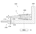
- FIG. 20 is a partial cross-sectional front view showing a dispenser according to an embodiment
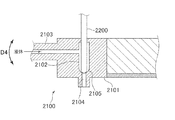
- FIG. 21 is a cross-sectional view showing a state in which the liquid discharge member of the dispenser of FIG. 20 is closed.
- FIG. 22 is a cross-sectional view showing a state in which the liquid discharge member of the dispenser of FIG. 20 is opened.
- the dispenser 2000 drives a liquid discharge member 2100 into which a liquid is introduced and discharges the introduced liquid, a valve 2200 for discharging and shutting off the liquid from the liquid discharge member 2100, and a valve 2200. It has an actuator 2300 and the like.
- the actuator 2300 has a configuration in which the displacement expanding mechanism 2 according to the first modification is provided with a drive unit 80.
- the liquid discharge member 2100 includes a main body portion 2101, a liquid chamber 2102 through which a valve 2200 formed in the main body portion 2101 is inserted, and a liquid introduction portion 2103 that introduces liquid into the liquid chamber 2102. It has a liquid discharge port 2104 that communicates with the bottom of the liquid chamber 2102, and a valve seat 2105 that is provided at the bottom of the liquid chamber 2102 and on which the tip of the valve 2200 is seated.
- the valve 2200 has a spherical rod-shaped tip and extends in the vertical direction, and the liquid chamber 2102 has a columnar shape corresponding to the shape of the valve 2200. As shown in FIG. 21, the valve 2200 usually has its tip seated on the valve seat 2105, and the liquid discharge port 2104 is closed. In this state, the liquid is not discharged.
- the valve 2200 is driven up and down in the displacement direction D4 by the actuator 2300.
- the liquid discharge port 2104 is opened as shown in FIG. 22, and the liquid is discharged from the liquid discharge port 2104.
- the actuator 2300 has the same structure as the actuator 1000 of FIG.
- a valve 2200 is attached to the working portion 40.
- the working portion 40 may be made of a high-strength aluminum material for weight reduction, and may be processed so that the central portion becomes a thin portion 501 as shown in the figure.
- the action unit 40 is driven upward, and the valve 2200 can be raised accordingly. Further, the valve 2200 can be lowered by releasing the application of the voltage to the piezoelectric element 20. Further, the valve 2200 may be moved up and down by causing the piezoelectric element 20 to contract and displace.
- the base 10 of the actuator 2300 is supported by the base 2400.
- the base 2400 also supports the liquid discharge member 2100.
- the liquid discharge port 2104 is closed by the valve 2200 in a state where no voltage is applied to the piezoelectric element 20, and the piezoelectric element 20 is extended to generate a displacement, which is shown in FIG.
- the valve 2200 may be raised to open the liquid discharge port 2104, and the liquid may be normally closed so that the liquid is discharged from the liquid discharge port 2104.
- valve 2200 when the voltage is not applied, the valve 2200 is in a state where the liquid discharge port 2104 is opened, and when the piezoelectric element 20 is contracted and displaced by the application of the voltage, the valve 2200 is lowered and the liquid discharge port is lowered. It may be a normal open in which the 2104 is closed.
- a plurality of displacement expansion mechanisms 1 may be arranged in series or in parallel and used in combination. At that time, it is also possible to connect a plurality of displacement expansion mechanisms 1 in series, that is, to connect the base 10 of the displacement expansion mechanism 1 and the action unit 40 of another displacement expansion mechanism 1. It is also possible to increase the displacement. In particular, such usage is effective in places where space is tightly restricted. Further, variations in the connection method such as connecting the two displacement expansion mechanisms 1 so that the connection angle is 90 ° can be considered.
- the piezoelectric element 20 is used as the expansion / contraction element, but the element is not particularly limited as long as it is an expansion / contraction element, and other elements having a contraction function such as a magnetostrictive element or a shape memory alloy. It is also possible to use.
- Displacement expansion mechanism 10 Base 11 Mounting part 20 Piezoelectric element 30 Supporting member 40 Acting part 50 Connecting member 70 Driving part 800 Polishing part 900 Polishing device 1000 Actuator 2000 Dispenser 3000 Air valve
Landscapes
- Engineering & Computer Science (AREA)
- Mechanical Engineering (AREA)
- General Engineering & Computer Science (AREA)
- General Electrical Machinery Utilizing Piezoelectricity, Electrostriction Or Magnetostriction (AREA)
- Locating Faults (AREA)
- Radiation Pyrometers (AREA)
- Measuring Temperature Or Quantity Of Heat (AREA)
- Grinding And Polishing Of Tertiary Curved Surfaces And Surfaces With Complex Shapes (AREA)
- Constituent Portions Of Griding Lathes, Driving, Sensing And Control (AREA)
Priority Applications (9)
| Application Number | Priority Date | Filing Date | Title |
|---|---|---|---|
| PCT/JP2020/000358 WO2021140598A1 (ja) | 2020-01-08 | 2020-01-08 | 変位拡大機構、アクチュエータ、研磨装置、電子部品処理装置、ディスペンサ、およびエアバルブ |
| JP2020550197A JP7001296B2 (ja) | 2020-01-08 | 2020-01-08 | 変位拡大機構、アクチュエータ、研磨装置、電子部品処理装置、ディスペンサ、およびエアバルブ |
| TW110100376A TWI891701B (zh) | 2020-01-08 | 2021-01-06 | 位移擴大機構、致動器、研磨裝置、電子零件處理裝置、分配器以及空氣閥 |
| CN202180008445.2A CN114930707B (zh) | 2020-01-08 | 2021-01-07 | 位移放大机构、致动器、抛光装置、电子零件处理装置、分配器及气阀 |
| JP2021570093A JP7633626B2 (ja) | 2020-01-08 | 2021-01-07 | 変位拡大機構、研磨装置、アクチュエータ、ディスペンサ、およびエアバルブ |
| KR1020227021191A KR20220122635A (ko) | 2020-01-08 | 2021-01-07 | 변위 확대 기구, 액추에이터, 연마 장치, 전자 부품 처리 장치, 디스펜서, 및 에어 밸브 |
| PCT/JP2021/000411 WO2021141095A1 (ja) | 2020-01-08 | 2021-01-07 | 変位拡大機構、アクチュエータ、研磨装置、電子部品処理装置、ディスペンサ、およびエアバルブ |
| US17/791,435 US12580499B2 (en) | 2020-01-08 | 2021-01-07 | Displacement magnifying mechanism, actuator, polishing device, electronic component processing apparatus, dispenser, and air valve |
| JP2021167612A JP7461058B2 (ja) | 2020-01-08 | 2021-10-12 | 変位拡大機構、研磨装置、アクチュエータ、ディスペンサ、およびエアバルブ |
Applications Claiming Priority (1)
| Application Number | Priority Date | Filing Date | Title |
|---|---|---|---|
| PCT/JP2020/000358 WO2021140598A1 (ja) | 2020-01-08 | 2020-01-08 | 変位拡大機構、アクチュエータ、研磨装置、電子部品処理装置、ディスペンサ、およびエアバルブ |
Publications (1)
| Publication Number | Publication Date |
|---|---|
| WO2021140598A1 true WO2021140598A1 (ja) | 2021-07-15 |
Family
ID=76788173
Family Applications (2)
| Application Number | Title | Priority Date | Filing Date |
|---|---|---|---|
| PCT/JP2020/000358 Ceased WO2021140598A1 (ja) | 2020-01-08 | 2020-01-08 | 変位拡大機構、アクチュエータ、研磨装置、電子部品処理装置、ディスペンサ、およびエアバルブ |
| PCT/JP2021/000411 Ceased WO2021141095A1 (ja) | 2020-01-08 | 2021-01-07 | 変位拡大機構、アクチュエータ、研磨装置、電子部品処理装置、ディスペンサ、およびエアバルブ |
Family Applications After (1)
| Application Number | Title | Priority Date | Filing Date |
|---|---|---|---|
| PCT/JP2021/000411 Ceased WO2021141095A1 (ja) | 2020-01-08 | 2021-01-07 | 変位拡大機構、アクチュエータ、研磨装置、電子部品処理装置、ディスペンサ、およびエアバルブ |
Country Status (6)
| Country | Link |
|---|---|
| US (1) | US12580499B2 (https=) |
| JP (3) | JP7001296B2 (https=) |
| KR (1) | KR20220122635A (https=) |
| CN (1) | CN114930707B (https=) |
| TW (1) | TWI891701B (https=) |
| WO (2) | WO2021140598A1 (https=) |
Families Citing this family (3)
| Publication number | Priority date | Publication date | Assignee | Title |
|---|---|---|---|---|
| DE102021121334A1 (de) * | 2021-04-27 | 2022-10-27 | Dürr Systems Ag | Piezo-Aktorvorrichtung |
| JP7741494B2 (ja) * | 2021-08-16 | 2025-09-18 | 株式会社サタケ | 圧電式バルブ |
| JP7720042B2 (ja) * | 2021-10-29 | 2025-08-07 | 株式会社サタケ | 圧電式バルブ |
Citations (5)
| Publication number | Priority date | Publication date | Assignee | Title |
|---|---|---|---|---|
| JPH11328890A (ja) * | 1998-05-15 | 1999-11-30 | Toshiba Corp | ヘッドアクチュエータ機構、およびこれを備えた磁気ディスク装置 |
| JP2007154965A (ja) * | 2005-12-02 | 2007-06-21 | Shimadzu Corp | 変位拡大機構 |
| JP2015177720A (ja) * | 2014-03-18 | 2015-10-05 | 並木精密宝石株式会社 | アクチュエータの駆動方法 |
| JP2016034225A (ja) * | 2014-07-28 | 2016-03-10 | 有限会社メカノトランスフォーマ | 圧電アクチュエータ |
| WO2019009035A1 (ja) * | 2017-07-07 | 2019-01-10 | 有限会社メカノトランスフォーマ | 変位拡大機構、研磨装置、アクチュエータ、ディスペンサ、及びエアバルブ |
Family Cites Families (13)
| Publication number | Priority date | Publication date | Assignee | Title |
|---|---|---|---|---|
| JP2864554B2 (ja) * | 1989-09-05 | 1999-03-03 | ブラザー工業株式会社 | 圧電素子の運動変換装置における圧電素子の組付方法 |
| JP3103467U (ja) * | 2004-02-18 | 2004-08-12 | 扇矢工事株式会社 | 管内面の研摩装置 |
| FR2959437B1 (fr) * | 2010-04-30 | 2012-06-08 | Centre Nat Rech Scient | Micro-actionneur et micro-pince |
| CN101913130B (zh) * | 2010-08-25 | 2012-10-10 | 清华大学 | 电致动夹持器 |
| JP5727781B2 (ja) | 2010-12-27 | 2015-06-03 | 有限会社メカノトランスフォーマ | 圧電素子の変位拡大機構 |
| FR2975935B1 (fr) * | 2011-06-06 | 2013-07-05 | Centre Nat Rech Scient | Outil pour pince microtechnique |
| US9640512B2 (en) * | 2014-07-24 | 2017-05-02 | Asm Technology Singapore Pte Ltd | Wire bonding apparatus comprising an oscillator mechanism |
| JP6475441B2 (ja) * | 2014-09-01 | 2019-02-27 | 株式会社フジキン | 圧電素子駆動式バルブ及び圧電素子駆動式バルブを備えた流量制御装置 |
| JP2018019529A (ja) * | 2016-07-28 | 2018-02-01 | セイコーエプソン株式会社 | 圧電アクチュエーター、圧電モーター、ロボットおよび電子部品搬送装置 |
| JP6955137B2 (ja) | 2016-11-14 | 2021-10-27 | シンフォニアテクノロジー株式会社 | 圧電式アクチュエータ及び圧電式バルブ |
| JP6918309B2 (ja) * | 2017-03-31 | 2021-08-11 | 有限会社メカノトランスフォーマ | 駆動装置および圧電アクチュエータ |
| JP6849217B2 (ja) | 2017-06-01 | 2021-03-24 | 有限会社メカノトランスフォーマ | ディスペンサ |
| JP2019103193A (ja) * | 2017-11-29 | 2019-06-24 | 国立大学法人秋田大学 | ベルクランク型駆動装置及び動力伝達型駆動装置 |
-
2020
- 2020-01-08 JP JP2020550197A patent/JP7001296B2/ja active Active
- 2020-01-08 WO PCT/JP2020/000358 patent/WO2021140598A1/ja not_active Ceased
-
2021
- 2021-01-06 TW TW110100376A patent/TWI891701B/zh active
- 2021-01-07 US US17/791,435 patent/US12580499B2/en active Active
- 2021-01-07 JP JP2021570093A patent/JP7633626B2/ja active Active
- 2021-01-07 KR KR1020227021191A patent/KR20220122635A/ko not_active Ceased
- 2021-01-07 WO PCT/JP2021/000411 patent/WO2021141095A1/ja not_active Ceased
- 2021-01-07 CN CN202180008445.2A patent/CN114930707B/zh active Active
- 2021-10-12 JP JP2021167612A patent/JP7461058B2/ja active Active
Patent Citations (5)
| Publication number | Priority date | Publication date | Assignee | Title |
|---|---|---|---|---|
| JPH11328890A (ja) * | 1998-05-15 | 1999-11-30 | Toshiba Corp | ヘッドアクチュエータ機構、およびこれを備えた磁気ディスク装置 |
| JP2007154965A (ja) * | 2005-12-02 | 2007-06-21 | Shimadzu Corp | 変位拡大機構 |
| JP2015177720A (ja) * | 2014-03-18 | 2015-10-05 | 並木精密宝石株式会社 | アクチュエータの駆動方法 |
| JP2016034225A (ja) * | 2014-07-28 | 2016-03-10 | 有限会社メカノトランスフォーマ | 圧電アクチュエータ |
| WO2019009035A1 (ja) * | 2017-07-07 | 2019-01-10 | 有限会社メカノトランスフォーマ | 変位拡大機構、研磨装置、アクチュエータ、ディスペンサ、及びエアバルブ |
Also Published As
| Publication number | Publication date |
|---|---|
| JP7633626B2 (ja) | 2025-02-20 |
| TWI891701B (zh) | 2025-08-01 |
| JP7001296B2 (ja) | 2022-01-19 |
| KR20220122635A (ko) | 2022-09-02 |
| JP2022009056A (ja) | 2022-01-14 |
| JPWO2021140598A1 (https=) | 2021-07-15 |
| TW202139494A (zh) | 2021-10-16 |
| JP7461058B2 (ja) | 2024-04-03 |
| JPWO2021141095A1 (https=) | 2021-07-15 |
| WO2021141095A1 (ja) | 2021-07-15 |
| CN114930707A (zh) | 2022-08-19 |
| US12580499B2 (en) | 2026-03-17 |
| US20230043346A1 (en) | 2023-02-09 |
| CN114930707B (zh) | 2025-08-26 |
Similar Documents
| Publication | Publication Date | Title |
|---|---|---|
| JP7217530B2 (ja) | 変位拡大機構、研磨装置、アクチュエータ、ディスペンサ、及びエアバルブ | |
| JP7461058B2 (ja) | 変位拡大機構、研磨装置、アクチュエータ、ディスペンサ、およびエアバルブ | |
| US6565333B2 (en) | Fluid discharge apparatus and fluid discharge method | |
| JP7058046B2 (ja) | ディスペンサ | |
| US8567921B2 (en) | Ink-jet apparatus | |
| CN112752618B (zh) | 液体涂敷装置 | |
| JP2022009056A5 (https=) | ||
| CN112752617B (zh) | 液体涂敷装置 | |
| JP6893710B1 (ja) | バルブ装置 | |
| JP2001271808A (ja) | エアベアリングシリンダ | |
| JP6918309B2 (ja) | 駆動装置および圧電アクチュエータ | |
| JP6892650B2 (ja) | 駆動装置 | |
| US20260001328A1 (en) | Inkjet device | |
| JP2022166778A (ja) | 圧電式バルブ | |
| JP2025138120A (ja) | 液吐出装置、及び液吐出方法 | |
| JPH0710185B2 (ja) | 積層形圧電セラミツクを駆動源としたアクチユエータ |
Legal Events
| Date | Code | Title | Description |
|---|---|---|---|
| ENP | Entry into the national phase |
Ref document number: 2020550197 Country of ref document: JP Kind code of ref document: A |
|
| 121 | Ep: the epo has been informed by wipo that ep was designated in this application |
Ref document number: 20912570 Country of ref document: EP Kind code of ref document: A1 |
|
| NENP | Non-entry into the national phase |
Ref country code: DE |
|
| 122 | Ep: pct application non-entry in european phase |
Ref document number: 20912570 Country of ref document: EP Kind code of ref document: A1 |