WO2021137271A1 - 飛行体 - Google Patents
飛行体 Download PDFInfo
- Publication number
- WO2021137271A1 WO2021137271A1 PCT/JP2020/000001 JP2020000001W WO2021137271A1 WO 2021137271 A1 WO2021137271 A1 WO 2021137271A1 JP 2020000001 W JP2020000001 W JP 2020000001W WO 2021137271 A1 WO2021137271 A1 WO 2021137271A1
- Authority
- WO
- WIPO (PCT)
- Prior art keywords
- frame
- flying object
- mounting portion
- air vehicle
- hovering
- Prior art date
- Legal status (The legal status is an assumption and is not a legal conclusion. Google has not performed a legal analysis and makes no representation as to the accuracy of the status listed.)
- Ceased
Links
Images


Classifications
-
- B—PERFORMING OPERATIONS; TRANSPORTING
- B64—AIRCRAFT; AVIATION; COSMONAUTICS
- B64C—AEROPLANES; HELICOPTERS
- B64C27/00—Rotorcraft; Rotors peculiar thereto
- B64C27/52—Tilting of rotor bodily relative to fuselage
-
- B—PERFORMING OPERATIONS; TRANSPORTING
- B64—AIRCRAFT; AVIATION; COSMONAUTICS
- B64C—AEROPLANES; HELICOPTERS
- B64C29/00—Aircraft capable of landing or taking-off vertically, e.g. vertical take-off and landing [VTOL] aircraft
- B64C29/0008—Aircraft capable of landing or taking-off vertically, e.g. vertical take-off and landing [VTOL] aircraft having its flight directional axis horizontal when grounded
-
- B—PERFORMING OPERATIONS; TRANSPORTING
- B64—AIRCRAFT; AVIATION; COSMONAUTICS
- B64D—EQUIPMENT FOR FITTING IN OR TO AIRCRAFT; FLIGHT SUITS; PARACHUTES; ARRANGEMENT OR MOUNTING OF POWER PLANTS OR PROPULSION TRANSMISSIONS IN AIRCRAFT
- B64D1/00—Dropping, ejecting, releasing or receiving articles, liquids, or the like, in flight
- B64D1/22—Taking-up articles from earth's surface
-
- B—PERFORMING OPERATIONS; TRANSPORTING
- B64—AIRCRAFT; AVIATION; COSMONAUTICS
- B64D—EQUIPMENT FOR FITTING IN OR TO AIRCRAFT; FLIGHT SUITS; PARACHUTES; ARRANGEMENT OR MOUNTING OF POWER PLANTS OR PROPULSION TRANSMISSIONS IN AIRCRAFT
- B64D9/00—Equipment for handling freight; Equipment for facilitating passenger embarkation or the like
-
- B—PERFORMING OPERATIONS; TRANSPORTING
- B64—AIRCRAFT; AVIATION; COSMONAUTICS
- B64U—UNMANNED AERIAL VEHICLES [UAV]; EQUIPMENT THEREFOR
- B64U10/00—Type of UAV
- B64U10/10—Rotorcrafts
- B64U10/13—Flying platforms
- B64U10/16—Flying platforms with five or more distinct rotor axes, e.g. octocopters
-
- B—PERFORMING OPERATIONS; TRANSPORTING
- B64—AIRCRAFT; AVIATION; COSMONAUTICS
- B64U—UNMANNED AERIAL VEHICLES [UAV]; EQUIPMENT THEREFOR
- B64U30/00—Means for producing lift; Empennages; Arrangements thereof
- B64U30/10—Wings
-
- B—PERFORMING OPERATIONS; TRANSPORTING
- B64—AIRCRAFT; AVIATION; COSMONAUTICS
- B64U—UNMANNED AERIAL VEHICLES [UAV]; EQUIPMENT THEREFOR
- B64U30/00—Means for producing lift; Empennages; Arrangements thereof
- B64U30/20—Rotors; Rotor supports
-
- B—PERFORMING OPERATIONS; TRANSPORTING
- B64—AIRCRAFT; AVIATION; COSMONAUTICS
- B64U—UNMANNED AERIAL VEHICLES [UAV]; EQUIPMENT THEREFOR
- B64U50/00—Propulsion; Power supply
- B64U50/10—Propulsion
- B64U50/19—Propulsion using electrically powered motors
-
- G—PHYSICS
- G05—CONTROLLING; REGULATING
- G05D—SYSTEMS FOR CONTROLLING OR REGULATING NON-ELECTRIC VARIABLES
- G05D1/00—Control of position, course, altitude or attitude of land, water, air or space vehicles, e.g. using automatic pilots
- G05D1/08—Control of attitude, i.e. control of roll, pitch, or yaw
- G05D1/0808—Control of attitude, i.e. control of roll, pitch, or yaw specially adapted for aircraft
- G05D1/0858—Control of attitude, i.e. control of roll, pitch, or yaw specially adapted for aircraft specially adapted for vertical take-off of aircraft
Definitions
- This disclosure relates to an air vehicle.
- flying objects such as drones or unmanned aerial vehicles (UAVs) (hereinafter collectively referred to as "flying objects") have become widespread.
- flying objects such as drones or unmanned aerial vehicles (UAVs) (hereinafter collectively referred to as "flying objects")
- UAVs unmanned aerial vehicles
- a multicopter type having a plurality of rotor blades can be mentioned (see, for example, Patent Document 1).
- one of the purposes of the present disclosure is to provide an air vehicle capable of efficiently improving speed performance and fuel efficiency.
- the aircraft according to this disclosure is An air vehicle capable of forward flight and hovering, Lift generator and A frame that holds the lift generating part and A mounting portion provided on the frame and for storing a mounting object is provided.
- the front projected area of the frame and the mounting portion during forward flight is smaller than the front projected area of the frame and the mounting portion during hovering.
- An air vehicle according to an embodiment of the present disclosure has, for example, the following configuration.
- An air vehicle capable of forward flight and hovering, Lift generator and A frame that holds the lift generating part and A mounting portion provided on the frame and for storing a mounting object is provided.
- the front projected area of the frame and the mounting portion during forward flight is smaller than the front projected area of the frame and the mounting portion during hovering.
- the lift generating part includes a rotary blade and includes a rotary blade.
- a support portion for supporting the rotor blade is further provided at the end portion of the frame.
- the support portion is an air vehicle that fixes the rotor blades in a non-rotatable manner.
- the support portion is a flying object that fixes the rotary wing so that the rotation axis of the rotary wing is in the forward direction of the flying object and in the direction of being inclined with respect to the frame.
- the lift generating section generates lift in the forward and upward directions.
- the air vehicle is an air vehicle in which the frame is in a horizontal posture.
- the mounting portion is an air vehicle having a frame and a connecting portion that is rotatably connected to the frame at least in the front-rear direction.
- the connecting portion is an air vehicle having an attitude control mechanism for controlling the attitude of the mounting portion.
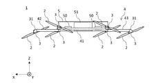
- FIG. 1 is a plan view of the flying object 1 according to the embodiment.
- FIG. 2 is a front view of the flying object 1 according to the present embodiment.
- FIG. 3 is a side view of the flying object 1 according to the present embodiment.
- the air vehicle 1 according to the present embodiment is, for example, an air vehicle capable of flying or hovering in the forward direction.
- the flying object 1 includes, for example, a rotary wing 2 (lift generating portion), a motor 3 for rotating the rotary wing 2, and a frame 4 for holding the rotary wing 2 and to which the motor 3 is attached. ..
- the front-rear direction of the flying object 1 is the Y-axis direction
- the left-right direction (or the horizontal direction) is the X-axis direction
- the vertical direction (or the vertical direction) is the Z-axis direction.
- the flying object 1 has the + Y direction as the forward direction.
- the rotor blade 2 rotates in response to the output from the motor 3.
- the rotation of the rotor 2 generates a propulsive force in the flying object 1.
- the rotor blade 2 is an example of a lift generating unit.
- each of the plurality of rotating blades is controlled to rotate clockwise or counterclockwise, or to stop, so that the flying object 1 moves in the vertical direction and the horizontal direction. , As well as swivel and yaw axis rotation is possible.
- the number of blades (rotors) of the rotary blade 2 of the present disclosure may be arbitrary (for example, 1, 2, 3, 4, or more blades).
- the shape of the blade can be any shape such as a flat shape, a bent shape, a twisted shape, a tapered shape, or a combination thereof.
- the shape of the blade may be fixed or may be variable. (For example, stretching, folding, folding, etc.).
- the blades may be symmetrical or asymmetrical (having differently shaped upper and lower surfaces).
- symmetric means that the upper and lower surface shapes are symmetric with respect to the chord line of the blade.
- Asymmetric means that it is not symmetrical as described above.
- the blades can be formed into an air foil, a wing, or a geometry suitable for generating dynamic aerodynamic forces (eg, lift, thrust) as the blades move through the air.
- the geometry of the blades can be appropriately selected to optimize the dynamic air characteristics of the blades, such as increasing lift and thrust and reducing drag.
- the rotary blade 2 may be a propulsion type (push type), a traction type (pull type), or a combination thereof.
- the motor 3 causes the rotary blade 2 to rotate. That is, the motor 3 is an example of a drive unit.
- the drive unit of the rotary blade 2 may be an engine or the like in addition to the motor.
- the vanes are driveable by the motor and rotate, for example, clockwise and / or counterclockwise, around the axis of rotation of the motor (eg, the major axis of the motor).
- the propeller (rotor blade 2) constituting the blade has a drive shaft whose output is transmitted from the power shaft of the motor via a pulley or the like, and the blade may rotate around the drive shaft.
- each blade can be controlled independently. For example, in a multicopter type air vehicle, some of the blades rotate in one direction and the other blades rotate in the other direction. The blades can all rotate at the same rotation speed, and can also rotate at different rotation speeds. The number of rotations can be determined automatically or manually based on the dimensions (for example, size, weight) or control state (speed, moving direction, etc.) of the moving body.
- the frame 4 is a member that supports the corresponding motor 3 and rotor blade 2, respectively.
- the frame 4 may be provided with a color-developing body such as an LED to indicate the flight state, flight direction, etc. of the rotary wing aircraft.
- the frame 4 according to the present embodiment can be formed of carbon, carbon fiber resin, glass fiber resin, stainless steel, aluminum, aluminum alloy, magnesium, magnesium alloy, or a material appropriately selected from a combination thereof. ..
- the frame 4 includes a first frame 40 and a second frame 41.
- the second frames 41 and 41 are horizontally laid side by side between the first frames 40 and 40 provided so as to be arranged substantially in parallel.
- the first frame 40 and the second frame 41 are connected by a known method such as a joint or caulking.
- the first frames 40, 40 are arranged at predetermined intervals along the X direction with the Y direction as the longitudinal direction.
- Rotor blades 2 are attached to both ends of the first frames 40, 40 via a motor 3.
- the second frames 41 and 41 are arranged at predetermined intervals along the Y direction with the X direction as the longitudinal direction.
- connection points between the two first frames 40 and 40 and the two second frames 41 and 41 are defined as V1 to V4.
- the frame 4 starts at a third frame 42 extending in the X direction from the first frame 40 starting from between the vertices V1 and V2 on the first frame 40, and between the vertices V3 and V4 on the first frame 40.
- a fourth frame 43 extending in the X direction from the first frame 40 is provided.
- a rotary blade 2 is attached to the end of the third frame 42 via a motor 3.
- a rotary blade 2 is attached to the end of the fourth frame 43 via a motor 3.
- a motor mount 31 that supports the rotor blade 2 and the motor 3 is provided at each end of the frame 4.
- the motor mount 31 is an example of a support portion.
- a motor mount 31 is provided so that the rotation axis RA of the rotary blade 2 is inclined in front of the flying object 1 and with respect to the frame 4.
- the motor mount 3 may have a tapered shape that narrows from the end of the frame 4 toward the longitudinal direction of the frame 4.
- the motor mount 31 according to the present embodiment is fixed at the end of the frame 4. That is, the motor mount 31 fixes the rotor blade 2 to the frame 4 so as not to rotate. That is, the rotor blade 2 itself does not rotate with respect to the frame 4.
- the mounting unit 5 is, for example, a mechanism for mounting and holding a load (loading object) 51.
- the battery 50 may be loaded on the mounting unit 5.
- the mounting portion 5 is provided on the frame 4 and stores the luggage 51.
- the batteries 50 are arranged side by side in the X direction with the luggage 51 in between.
- the number of batteries 50 to be loaded is not particularly limited.
- the mounting portion 5 may have not only a square portion having V1 to V4 as vertices but also a square portion protruding from the square portion in the ⁇ Y direction.
- the mounting portion 5 may be fixed to the frame 4 so as not to rotate. Further, the mounting portion 5 may have a mechanism that can rotate with respect to the frame 4.
- the mounting portion 5 has a hinge (connecting portion) 52 that connects the housing of the mounting portion 5 and the frame 4.
- the hinge 52 as a fulcrum, the mounting portion 5 is configured to be rotatable in the pitch direction with respect to the frame 4.
- the limit of the angle at which the mounting portion 5 rotates with respect to the frame 4 via the hinge 52 is not particularly limited.
- the orientation of the mounting portion 5 so that the luggage 51 does not tilt even when the flying object 1 is hovering from the ground Gr in a backward leaning posture. Can be kept horizontal.
- the cargo 51 can be held in a stable state even during flight and delivered to the destination.
- the hinge 52 according to the present embodiment rotates the mounting portion 5 only in the front-rear direction (that is, the pitch direction), which is the same direction as the traveling direction.
- the mounting portion 5 may be further rotated in the left-right direction (roll direction and / or yaw direction).
- the hinge 52 may have a mechanism such as a gimbal that actively controls the posture of the mounting portion 5 by a motor or the like. This makes it possible to control the attitude of the mounting unit 5 during flight. Then, the wobbling (natural vibration, etc.) of the mounting portion 5 is further reduced, and the package 51 can be delivered more stably.
- the hinge 52 may be configured to be connected to the luggage 51 instead of the mounting portion 5.
- the shape and / or mechanism of the mounting portion 5 is not particularly limited as long as the luggage 51 can be stored and held. Further, the mechanism for holding the position and inclination of the luggage 51 mounted on the mounting portion 5 may be, for example, a tilt mechanism for tilting the luggage 51. Further, as described above, the mounting portion 5 does not necessarily have a structure that can rotate with respect to the frame 4.
- the flying object 1 in the present embodiment does not have a landing gear in order to reduce the weight. Therefore, in the present embodiment, when the flying object 1 lands, the mounting portion 5 exerts the function of the landing gear.
- landing gears may be appropriately provided on the frame 4, the mounting portion 5, and the like.
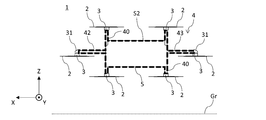
- FIG. 5 is a side view showing the flight state of the flying object 1 during hovering according to the present embodiment.
- FIG. 3 is also a side view showing the flight state of the flying object 1 during horizontal flight according to the present embodiment.
- the flying object 1 when the flying object 1 is hovering, the flying object 1 takes a backward leaning posture so that the lift obtained by the rotary blade 2 is upward.
- the frame 4 becomes horizontal, and the rotation axis RA of the rotor 2 faces in the Y-axis direction and diagonally upward.
- the lift obtained from the rotor 2 is composed of a front component and an upper component.
- the front projected area means the area of the projected area of the frame 4 and the mounting portion 5 when the flying object 1 is viewed from the front in the horizontal direction (that is, when viewed in the Y-axis direction).
- the front surface of the flying object 1 during horizontal flight and hovering is imaged from the horizontal direction, and the area occupied by the frame 4 and the mounting portion 5 in the captured image is the size of the actual flying object 1. It is obtained by calculating based on.
- the area surrounded by the thick broken line in FIG. 6 indicates the projected area S1 of the aircraft during forward flight.
- the area surrounded by the thick broken line in FIG. 7 indicates the projected area S2 of the airframe during hovering.
- the frame 4 and the mounting portion 5 occupy most of the components of the flying object 1, and are a major factor in air resistance during flight.
- the projection area S1 during forward flight is narrower than the projection area S2 during hovering. That is, in the flying object 1 in the present embodiment, the front projected area during forward flight is smaller than the front projected area during hovering.
- a conventional flying object when the rotor is fixed to the frame, the rotor faces upward when the frame becomes horizontal. Then, when flying forward, the air vehicle leans forward in the pitch direction. When the flying object tilts forward, the projection area from the front of the mounting portion and the frame of the flying object becomes large. That is, in the conventional flying object, the projected area is larger during forward flight than during hovering. In this case, the air resistance that the flying object receives from the front tends to increase.
- the flying object 1 according to the present embodiment has a smaller projected area from the front when flying forward than when hovering. Then, the air resistance received from the front of the airframe 1 is reduced. That is, the configuration of the flying object 1 according to the present embodiment can efficiently improve the speed performance and fuel efficiency during forward flight.
- the above-mentioned flying object 1 has, for example, the functional block shown in FIG.
- the functional block of FIG. 8 has a minimum reference configuration, and the functional block of the aircraft 1 according to the present embodiment is not limited to such an example.
- the flight controller is a so-called processing unit.
- the processing unit can have one or more processors, such as a programmable processor (eg, a central processing unit (CPU)).
- the processing unit has a memory (not shown), and the memory can be accessed.
- Memory stores logic, code, and / or program instructions that a processing unit can execute to perform one or more steps.
- the memory may include, for example, a separable medium such as an SD card or random access memory (RAM) or an external storage device.
- the data acquired from the cameras or sensors may be transmitted and stored directly in the memory. For example, still image / moving image data taken by a camera or the like is recorded in an internal memory or an external memory.
- the processing unit includes a control module configured to control the state of the aircraft.
- the control module adjusts the spatial placement, velocity, and / or acceleration of an air vehicle with six degrees of freedom (translational motion x, y and z, and rotational motion ⁇ x , ⁇ y and ⁇ z).
- the control module can control one or more of the states of the mounting unit and the sensors.
- the processing unit is capable of communicating with a transmitter / receiver configured to transmit and / or receive data from one or more external devices (eg, terminals, display devices, or other remote controls).
- the transmitter / receiver can use any suitable communication means such as wired communication or wireless communication.
- the transmitter / receiver uses one or more of local area network (LAN), wide area network (WAN), infrared, wireless, WiFi, point-to-point (P2P) network, telecommunications network, cloud communication, and the like. be able to.
- the transmitter / receiver can transmit and / or receive one or more of the data acquired by the sensors, the processing result generated by the processing unit, the predetermined control data, the user command from the terminal or the remote control, and the like. ..
- the sensors according to this embodiment may include an inertial sensor (accelerometer, gyro sensor), GPS sensor, proximity sensor (eg, rider), or vision / image sensor (eg, camera).
- an inertial sensor accelerelerometer, gyro sensor
- GPS sensor GPS sensor
- proximity sensor eg, rider
- vision / image sensor eg, camera
- the aircraft of the present disclosure can be expected to be used as an aircraft for physical distribution and as an industrial aircraft in warehouses and factories.
- the aircraft of the present disclosure can be used in airplane-related industries such as multicopter drones.
- the present disclosure can be suitably used as an aerial vehicle equipped with a camera or the like.
- the technology can also be used in various industries such as security, agriculture, and infrastructure monitoring.
- Aircraft Rotor (lift generator) 3 Motor 4 Frame 5 Mounting part 31 Motor mount (support part) 51 Luggage (object to be loaded) 52 Hinge (connection part) S1 Projection area on the front of the aircraft during forward flight S2 Projection area on the front of the aircraft during hovering
Landscapes
- Engineering & Computer Science (AREA)
- Aviation & Aerospace Engineering (AREA)
- Mechanical Engineering (AREA)
- Chemical & Material Sciences (AREA)
- Combustion & Propulsion (AREA)
- Remote Sensing (AREA)
- Radar, Positioning & Navigation (AREA)
- Physics & Mathematics (AREA)
- General Physics & Mathematics (AREA)
- Automation & Control Theory (AREA)
- Toys (AREA)
Priority Applications (9)
| Application Number | Priority Date | Filing Date | Title |
|---|---|---|---|
| JP2021568448A JP7137257B2 (ja) | 2020-01-01 | 2020-01-01 | 飛行体 |
| EP20910289.6A EP4086170A4 (en) | 2020-01-01 | 2020-01-01 | AIRCRAFT |
| US17/790,707 US20230033507A1 (en) | 2020-01-01 | 2020-01-01 | Aircraft |
| PCT/JP2020/000001 WO2021137271A1 (ja) | 2020-01-01 | 2020-01-01 | 飛行体 |
| CN202011539064.0A CN113060277A (zh) | 2020-01-01 | 2020-12-23 | 飞行体 |
| CN202023127824.5U CN214325365U (zh) | 2020-01-01 | 2020-12-23 | 飞行体 |
| JP2022134700A JP2022162125A (ja) | 2020-01-01 | 2022-08-26 | 飛行体 |
| JP2024099819A JP7726552B2 (ja) | 2020-01-01 | 2024-06-20 | 飛行体 |
| JP2025128512A JP2025156467A (ja) | 2020-01-01 | 2025-07-31 | 飛行体 |
Applications Claiming Priority (1)
| Application Number | Priority Date | Filing Date | Title |
|---|---|---|---|
| PCT/JP2020/000001 WO2021137271A1 (ja) | 2020-01-01 | 2020-01-01 | 飛行体 |
Publications (1)
| Publication Number | Publication Date |
|---|---|
| WO2021137271A1 true WO2021137271A1 (ja) | 2021-07-08 |
Family
ID=76559028
Family Applications (1)
| Application Number | Title | Priority Date | Filing Date |
|---|---|---|---|
| PCT/JP2020/000001 Ceased WO2021137271A1 (ja) | 2020-01-01 | 2020-01-01 | 飛行体 |
Country Status (5)
| Country | Link |
|---|---|
| US (1) | US20230033507A1 (https=) |
| EP (1) | EP4086170A4 (https=) |
| JP (4) | JP7137257B2 (https=) |
| CN (2) | CN214325365U (https=) |
| WO (1) | WO2021137271A1 (https=) |
Cited By (1)
| Publication number | Priority date | Publication date | Assignee | Title |
|---|---|---|---|---|
| JP2023086311A (ja) * | 2021-12-10 | 2023-06-22 | 株式会社エクセディ | ドローン用モータ |
Families Citing this family (5)
| Publication number | Priority date | Publication date | Assignee | Title |
|---|---|---|---|---|
| GB201802611D0 (en) * | 2018-02-17 | 2018-04-04 | Panelplane Ltd | Teleporter |
| US20230033507A1 (en) * | 2020-01-01 | 2023-02-02 | Aeronext Inc. | Aircraft |
| JP6952380B1 (ja) * | 2020-08-11 | 2021-10-20 | 株式会社エアロネクスト | 移動体 |
| EP4393819A4 (en) * | 2021-08-23 | 2025-07-30 | Aeronext Inc | Flying object |
| EP4711283A1 (en) * | 2024-09-13 | 2026-03-18 | Fuvex Civil, SL | Unmanned aerial vehicle for lineal infrastructure inspection |
Citations (5)
| Publication number | Priority date | Publication date | Assignee | Title |
|---|---|---|---|---|
| JP2013129301A (ja) | 2011-12-21 | 2013-07-04 | Ihi Aerospace Co Ltd | 小型無人機 |
| JP2013531573A (ja) * | 2010-05-26 | 2013-08-08 | エアロヴァイロンメント インコーポレイテッド | 再構成可能なバッテリ式の無人機システム |
| JP6086519B1 (ja) * | 2016-10-03 | 2017-03-01 | 株式会社0 | 配達用回転翼機 |
| JP2018203226A (ja) * | 2018-03-13 | 2018-12-27 | 株式会社エアロネクスト | 飛行体 |
| JP2019026233A (ja) * | 2017-07-27 | 2019-02-21 | 株式会社Mmラボ | 無人航空機 |
Family Cites Families (9)
| Publication number | Priority date | Publication date | Assignee | Title |
|---|---|---|---|---|
| US6824095B2 (en) * | 2001-11-29 | 2004-11-30 | Youbin Mao | VSTOL vehicle |
| US8733690B2 (en) | 2009-08-24 | 2014-05-27 | Joby Aviation, Inc. | Lightweight vertical take-off and landing aircraft and flight control paradigm using thrust differentials |
| US20140061376A1 (en) * | 2010-05-26 | 2014-03-06 | Aerovironment Inc | Reconfigurable battery-operated vehicle system |
| CN106043679B (zh) * | 2016-07-28 | 2018-09-07 | 易瓦特科技股份公司 | 多轴动力源无人飞行设备 |
| EP3366582B1 (en) | 2017-02-28 | 2019-07-24 | AIRBUS HELICOPTERS DEUTSCHLAND GmbH | A multirotor aircraft with an airframe and a thrust producing units arrangement |
| JP6707761B2 (ja) * | 2017-09-27 | 2020-06-10 | 株式会社石川エナジーリサーチ | エンジン搭載自立型飛行装置 |
| JP3217820U (ja) | 2018-04-27 | 2018-09-06 | 東光鉄工株式会社 | ドローン |
| JP6606648B1 (ja) * | 2018-07-17 | 2019-11-20 | 株式会社プロドローン | 無人航空機 |
| US20230033507A1 (en) * | 2020-01-01 | 2023-02-02 | Aeronext Inc. | Aircraft |
-
2020
- 2020-01-01 US US17/790,707 patent/US20230033507A1/en not_active Abandoned
- 2020-01-01 WO PCT/JP2020/000001 patent/WO2021137271A1/ja not_active Ceased
- 2020-01-01 JP JP2021568448A patent/JP7137257B2/ja active Active
- 2020-01-01 EP EP20910289.6A patent/EP4086170A4/en active Pending
- 2020-12-23 CN CN202023127824.5U patent/CN214325365U/zh active Active
- 2020-12-23 CN CN202011539064.0A patent/CN113060277A/zh active Pending
-
2022
- 2022-08-26 JP JP2022134700A patent/JP2022162125A/ja active Pending
-
2024
- 2024-06-20 JP JP2024099819A patent/JP7726552B2/ja active Active
-
2025
- 2025-07-31 JP JP2025128512A patent/JP2025156467A/ja active Pending
Patent Citations (5)
| Publication number | Priority date | Publication date | Assignee | Title |
|---|---|---|---|---|
| JP2013531573A (ja) * | 2010-05-26 | 2013-08-08 | エアロヴァイロンメント インコーポレイテッド | 再構成可能なバッテリ式の無人機システム |
| JP2013129301A (ja) | 2011-12-21 | 2013-07-04 | Ihi Aerospace Co Ltd | 小型無人機 |
| JP6086519B1 (ja) * | 2016-10-03 | 2017-03-01 | 株式会社0 | 配達用回転翼機 |
| JP2019026233A (ja) * | 2017-07-27 | 2019-02-21 | 株式会社Mmラボ | 無人航空機 |
| JP2018203226A (ja) * | 2018-03-13 | 2018-12-27 | 株式会社エアロネクスト | 飛行体 |
Cited By (1)
| Publication number | Priority date | Publication date | Assignee | Title |
|---|---|---|---|---|
| JP2023086311A (ja) * | 2021-12-10 | 2023-06-22 | 株式会社エクセディ | ドローン用モータ |
Also Published As
| Publication number | Publication date |
|---|---|
| JP2022162125A (ja) | 2022-10-21 |
| CN214325365U (zh) | 2021-10-01 |
| EP4086170A1 (en) | 2022-11-09 |
| JPWO2021137271A1 (https=) | 2021-07-08 |
| CN113060277A (zh) | 2021-07-02 |
| US20230033507A1 (en) | 2023-02-02 |
| JP7726552B2 (ja) | 2025-08-20 |
| EP4086170A4 (en) | 2023-09-27 |
| JP2025156467A (ja) | 2025-10-14 |
| JP7137257B2 (ja) | 2022-09-14 |
| JP2024111216A (ja) | 2024-08-16 |
Similar Documents
| Publication | Publication Date | Title |
|---|---|---|
| JP7726552B2 (ja) | 飛行体 | |
| JP6952389B1 (ja) | 飛行体 | |
| JP6384013B1 (ja) | 飛行体 | |
| JP6664822B1 (ja) | 飛行体 | |
| JP6578477B2 (ja) | 回転翼機 | |
| JP2021008270A (ja) | 飛行体 | |
| JP2024074891A (ja) | 回転翼機 | |
| JP7466217B2 (ja) | 離着陸システム | |
| US12246828B2 (en) | Aerial vehicle having a first wing and a second wing that tilt and rotate to form an inverted V-shape | |
| JP2019182390A (ja) | 飛行体 | |
| JP2021049965A (ja) | 飛行体 | |
| JP7779566B2 (ja) | 無人航空機用フレーム組立体及びこれを備える無人航空機 | |
| JP7006930B2 (ja) | 回転翼機 | |
| WO2021053829A1 (ja) | 飛行体 | |
| JP2020108997A (ja) | 有人飛行体 | |
| JP6767070B2 (ja) | 飛行体 | |
| JPWO2020021650A1 (ja) | プロペラ、モータ部品及びこれを備えた飛行体 | |
| JP2022075257A (ja) | アタッチメント及び飛行体 | |
| WO2021024370A1 (ja) | 飛行体 | |
| WO2021059323A1 (ja) | アタッチメント及び飛行体 |
Legal Events
| Date | Code | Title | Description |
|---|---|---|---|
| 121 | Ep: the epo has been informed by wipo that ep was designated in this application |
Ref document number: 20910289 Country of ref document: EP Kind code of ref document: A1 |
|
| ENP | Entry into the national phase |
Ref document number: 2021568448 Country of ref document: JP Kind code of ref document: A |
|
| NENP | Non-entry into the national phase |
Ref country code: DE |
|
| ENP | Entry into the national phase |
Ref document number: 2020910289 Country of ref document: EP Effective date: 20220801 |