WO2021132353A1 - 衣服用ファン装置及びファン付き衣服 - Google Patents
衣服用ファン装置及びファン付き衣服 Download PDFInfo
- Publication number
- WO2021132353A1 WO2021132353A1 PCT/JP2020/048210 JP2020048210W WO2021132353A1 WO 2021132353 A1 WO2021132353 A1 WO 2021132353A1 JP 2020048210 W JP2020048210 W JP 2020048210W WO 2021132353 A1 WO2021132353 A1 WO 2021132353A1
- Authority
- WO
- WIPO (PCT)
- Prior art keywords
- fan device
- wall surface
- rib
- clothing
- fan
- Prior art date
- Legal status (The legal status is an assumption and is not a legal conclusion. Google has not performed a legal analysis and makes no representation as to the accuracy of the status listed.)
- Ceased
Links
Images








Classifications
-
- A—HUMAN NECESSITIES
- A41—WEARING APPAREL
- A41D—OUTERWEAR; PROTECTIVE GARMENTS; ACCESSORIES
- A41D13/00—Professional, industrial or sporting protective garments, e.g. surgeons' gowns or garments protecting against blows or punches
- A41D13/002—Professional, industrial or sporting protective garments, e.g. surgeons' gowns or garments protecting against blows or punches with controlled internal environment
-
- F—MECHANICAL ENGINEERING; LIGHTING; HEATING; WEAPONS; BLASTING
- F04—POSITIVE - DISPLACEMENT MACHINES FOR LIQUIDS; PUMPS FOR LIQUIDS OR ELASTIC FLUIDS
- F04D—NON-POSITIVE-DISPLACEMENT PUMPS
- F04D25/00—Pumping installations or systems
- F04D25/02—Units comprising pumps and their driving means
- F04D25/08—Units comprising pumps and their driving means the working fluid being air, e.g. for ventilation
-
- F—MECHANICAL ENGINEERING; LIGHTING; HEATING; WEAPONS; BLASTING
- F04—POSITIVE - DISPLACEMENT MACHINES FOR LIQUIDS; PUMPS FOR LIQUIDS OR ELASTIC FLUIDS
- F04D—NON-POSITIVE-DISPLACEMENT PUMPS
- F04D29/00—Details, component parts, or accessories
- F04D29/40—Casings; Connections of working fluid
- F04D29/52—Casings; Connections of working fluid for axial pumps
- F04D29/54—Fluid-guiding means, e.g. diffusers
Definitions
- This disclosure relates to a clothing fan device.
- Patent Document 1 describes a technique related to a clothing fan device.
- the garment fan device is a garment fan device that is attached to the garment.
- the clothing fan device includes a mixed flow fan having a plurality of blades, a motor for rotating the mixed flow fan, and a housing for accommodating the mixed flow fan and the motor.
- the housing has a plurality of intake ports and an intake portion having a first rib structure that defines the plurality of intake ports.
- the first rib structure has a first rib extending along the direction of rotation of the mixed flow fan.
- the first rib has first and second wall surfaces. The first wall surface is located inside the first virtual line that passes through the first edge on the blade side of the first wall surface and extends along the axial direction of the mixed flow fan.
- the garment with a fan includes a garment and the above-mentioned garment fan device attached to the garment.
- FIG. 1 is a schematic view showing the appearance of the garment 1 with a fan.
- the garment 1 with a fan includes a garment 2 and a garment fan device 10 attached to the garment 2.
- FIG. 2 is a schematic view showing the appearance of the garment 2. 1 and 2 show the back side of the garment 2.
- the clothes fan device 10 is attached to, for example, the lower part of the back surface 3 of the clothes 2.
- a mounting hole 4 for mounting the garment fan device 10 to the garment 2 is provided in the lower portion of the back surface 3 of the garment 2.
- the clothing fan device 10 is mounted in the mounting hole 4.
- two mounting holes 4 arranged side by side are provided in the lower portion of the back surface 3 of the garment 2.
- a garment fan device 10 is attached to each attachment hole 4.
- the clothing fan device 10 may be simply referred to as a fan device 10.
- Each fan device 10 takes in air from one side and discharges the taken in air from the other side.
- Each fan device 10 is attached to the clothes 2 so that the side that takes in air (that is, the intake side) is located on the outside of the clothes 2 and the side that discharges air (that is, the exhaust side) is located inside the clothes 2.
- each fan device 10 takes in air from the outside to the inside of the garment 2 through the mounting holes 4.
- the air taken into the inside of the clothes 2 is discharged to the outside of the clothes 2 from the cuffs and the neck of the clothes 2 by the operation of each fan device 10. This makes it possible to cool the body of the person wearing the clothes 2.
- the mounting hole 4 of the garment 2 serves as an intake port for the cooling air
- the cuffs and neck of the garment 2 serve as an exhaust port for the cooling air.
- the number of fan devices 10 attached to the clothes 2 may be one or three or more. Further, the mounting position of the fan device 10 with respect to the clothes 2 is not limited to the examples of FIGS. 1 and 2. Further, in the above example, the garment 2 to which the fan device 10 is attached is a jacket, but it may be a garment other than the jacket. For example, the garment 2 may be trousers. In this case, the fan device 10 may be attached to the side surface of the trousers, for example.
- the structure of the fan device 10 will be described with the side on which the fan device 10 takes in air as the front side and the side on which the fan device 10 discharges air as the rear side.
- FIG. 3 to 5 are schematic views showing an example of the structure of the fan device 10.
- FIG. 3 shows a state in which the fan device 10 is viewed from the front side
- FIG. 4 shows a state in which the fan device 10 is viewed from the rear side.
- FIG. 5 shows the cross-sectional structure of the arrows A1-A1 of FIG.
- FIG. 5 shows the fan device 10 attached to the garment 2.
- the lower side of the garment 2 in FIG. 5 shows the inside 950 of the garment 2 (in other words, the human body side of the garment 2).
- the upper side of the garment 2 in FIG. 5 shows the outer side 951 of the garment 2.
- the upper side of FIGS. 3 and 4 will be referred to as the upper side of the fan device 10
- the lower side of FIGS. 3 and 4 will be referred to as the lower side of the fan device 10.
- the fan device 10 includes a main body portion 11 and a fixing member 90 for fixing the main body portion 11 to the clothes 2.
- the main body 11 includes a housing 12, a mixed flow fan 13, a motor 14, and a connector 15.
- the motor 14 is, for example, a DC motor.
- the housing 12 includes a housing body 12a and a cover member 12b.
- the cover member 12b is attached to the housing body 12a.
- the mixed flow fan 13, the motor 14, and the connector 15 are housed in the housing body 12a.
- the fixing member 90 is a member for fixing the housing 12 to the garment 2.
- the housing body 12a is made of, for example, resin.
- the outer shape of the housing body 12a is, for example, substantially circular when viewed from the front side or the rear side.
- the housing body 12a includes a front side portion 20 and a rear side portion 25.
- the outer shape of the front side portion 20 is substantially circular when viewed from the front side.
- the front side portion 20 includes a front surface portion 200, a tubular portion 210, and a flange portion 220.
- the front surface portion 200 includes a plurality of intake ports 201 and a rib structure 202 that defines the plurality of intake ports 201. It can be said that the front surface portion 200 is an intake portion that takes in the air outside the housing 12 into the housing 12.
- the central portion 205 of the front surface portion 200 is a closed region in which the intake port 201 is not provided when viewed from the intake side.
- the outer shape of the central portion 205 is, for example, a circle.
- the front surface portion 200 may be referred to as an intake portion 200.
- the tubular portion 210 is provided on the peripheral edge of the front surface portion 200 so as to project rearward from the peripheral edge while surrounding the peripheral edge of the front surface portion 200.
- the flange portion 220 is provided at the peripheral end portion of the tubular portion 210 on the intake side so as to surround the front surface portion 200.
- the flange portion 220 is provided at the peripheral end portion on the intake side of the outer peripheral surface of the tubular portion 210.
- the flange portion 220 projects in the radial direction of the front surface portion 200 from the peripheral end portion of the tubular portion 210 on the intake side.
- a male screw portion 211 that is screwed with the female screw portion 910 of the fixing member 90, which will be described later, is formed on the outer peripheral surface of the tubular portion 210.
- the rib structure 202 of the front surface portion 200 includes a plurality of linear ribs 203 extending along the radial direction of the front surface portion 200, and a plurality of circular ribs 204 extending along the circumferential direction of the front surface portion 200.
- the rib 203 may be referred to as a radial rib 203
- the rib 204 may be referred to as a circumferential rib 204.
- the plurality of radial ribs 203 extend radially from the central portion 205.
- the plurality of circumferential ribs 204 are arranged concentrically so as to surround the central portion 205.
- Each circumferential rib 204 is arranged so as to connect a plurality of ribs 203 extending radially.
- the rib structure 202 includes, for example, 13 radial ribs 203 and 3 circumferential ribs 204.
- the configuration of the rib structure 202 is not limited to the above example.
- the number of radial ribs 203 may be other than 13.
- the number of circumferential ribs 204 may be other than three.
- the outer shape of the rear side portion 25 is substantially circular when viewed from the rear side.
- the rear side portion 25 includes a back surface portion 250 and a tubular portion 260.
- the tubular portion 260 is provided on the peripheral edge so as to project from the peripheral edge to the front side while surrounding the peripheral edge of the back surface portion 250.
- a plurality of exhaust ports 270 are provided on the back surface portion 250 and the tubular portion 260.
- the plurality of exhaust ports 270 are provided so as to avoid the central portion of the back surface portion 250.
- the rear side portion 25 including the back surface portion 250 and the tubular portion 260 functions as an exhaust portion for exhausting the air inside the housing 12 to the outside of the housing 12.
- the rear side portion 25 includes a plurality of exhaust ports 270 and a rib structure 2800 that defines the plurality of exhaust ports 270.
- the rear side portion 25 may be referred to as an exhaust portion 25.
- the tubular portion 210 of the front side portion 20 and the tubular portion 260 of the rear side portion 25 are connected to each other, and form a tubular peripheral wall portion (in other words, a side surface portion) 29 of the entire housing 12.
- a tubular peripheral wall portion in other words, a side surface portion
- the central portion of the back surface portion 250 is recessed, and the accommodating recess 221 for accommodating the motor 14 and the connector 15 is formed in the central portion.
- the accommodating recess 221 has an opening surface 222 on the surface of the housing 12.
- the connector 15 is located below the motor 14 in the accommodating recess 221.
- the accommodating recess 221 has a motor accommodating portion 224 accommodating the motor 14 and a connector accommodating portion 225 accommodating the connector 15.
- the motor accommodating portion 224 is a tubular accommodating portion with one end closed. It can be said that the motor accommodating portion 224 is a tubular recess.
- the outer shape of the motor accommodating portion 224 is circular when viewed from the intake side.
- the motor 14 is fixed in the motor accommodating portion 224.
- the connector 15 is fixed in the connector accommodating portion 225.
- the connector accommodating portion 225 is located below the motor accommodating portion 224 and is connected to the motor accommodating portion 224.
- the cover member 12b is made of, for example, resin.
- the cover member 12b is attached to the back surface portion 250 and covers the opening surface 222 of the accommodating recess 221. As a result, the motor 14 and the connector 15 are covered with the cover member 12b.
- the cover member 12b is fixed to the back surface portion 250 by, for example, a screw 18. In this example, the cover member 12b is fixed to the back surface portion 250 by two screws 18. When the fan device 10 is viewed from the exhaust side, the cover member 12b is surrounded by the exhaust portion 25 as shown in FIG.
- the method of attaching the cover member 12b to the back surface portion 250 is not limited to this.
- connection cable extending from the battery device that generates the power supply for the fan device 10 is connected to the connector 15.
- the electric power output from the battery device is supplied to the connector 15 through the connection cable.
- a connector is provided at the end of the connection cable.
- the connector of the connection cable is connected to the connector 15.
- the electric power supplied to the connector 15 is supplied to the motor 14. As a result, the motor 14 can rotate the mixed flow fan 13 based on the electric power generated by the battery device.
- the lower portion of the connector accommodating portion 225 in the back surface portion 250 is recessed, and the recessed portion 251 is formed in the portion.
- the recess 251 extends downward and reaches the peripheral edge of the back surface 250.
- An insertion port into which the connector of the connection cable is inserted is provided in the lower wall portion of the connector accommodating portion 225 adjacent to the recess 251.
- the connector of the connection cable is connected to the connector 15 from the lower side after being inserted into the insertion slot.
- the recess 251 exists on the lower side of the connector 15, the connector of the connection cable can be easily connected to the connector 15 from the lower side.
- a plurality of rib structures 2800 included in the exhaust portion 25 extend from the back surface portion 250 toward the tubular portion 260 along the radial direction of the rear side portion 25 and reach the vicinity of the peripheral edge on the front side portion 20 side of the tubular portion 260.
- Ribs 280 are provided.
- the plurality of ribs 280 includes a plurality of ribs 281, a plurality of ribs 282, a rib 283, a rib 284, a rib 285, and a plurality of ribs 286.
- the rib structure 2800 includes a plurality of ribs 290 provided on the back surface portion 250 extending along the circumferential direction of the rear side portion 25.
- the plurality of ribs 290 include a plurality of ribs 291 and a plurality of ribs 292, ribs 293, and ribs 294.
- the ribs 280 to 286 may be referred to as radial ribs 280 to 286, respectively.
- the ribs 290 to 294 may be referred to as circumferential ribs 290 to 294, respectively.
- the plurality of radial ribs 281 extend radially from the accommodating recess 221.
- the plurality of ribs 281 are provided in addition to the recess 251 located below the housing recess 221.
- the rib structure 2800 includes, for example, 11 radial ribs 281.
- the plurality of circumferential ribs 291 have a substantially circular shape, and are arranged concentrically so as to substantially surround the accommodating recess 221.
- Each circumferential rib 291 is arranged so as to connect a plurality of radial ribs 281 extending radially.
- Each circumferential rib 291 has a circular shape with a part cut off, and is provided in addition to the recess 251 located below the accommodating recess 221.
- the rib structure 2800 includes, for example, two circumferential ribs 291.
- the plurality of radial ribs 282 extend radially from the outer circumferential rib 291 of the two circumferential ribs 291.
- the plurality of radial ribs 282 are provided in addition to the recess 251.
- the rib structure 2800 includes, for example, 10 radial ribs 282.
- the radial ribs 281 and the radial ribs 282 are alternately arranged in the circumferential direction of the rear portion 25.
- the radial rib 283 extends along the radial direction of the rear side portion 25 from the inner circumferential rib 291 of the two circumferential ribs 291 and passes through the recess 251 on the front side portion 20 side of the tubular portion 260. It reaches near the peripheral edge.
- the radial rib 284 extends from the accommodating recess 221 along the radial direction of the rear side portion 25, passes through the recess 251 and reaches the vicinity of the peripheral edge of the tubular portion 260 on the front side portion 20 side.
- the plurality of circumferential ribs 292 are located in the recesses 251 and connect the radial ribs 283 and the radial ribs 284.
- the rib structure 2800 includes, for example, two circumferential ribs 292.
- the radial rib 285 extends along the radial direction of the rear side portion 25 from the inner circumferential rib 292 of the two circumferential ribs 292.
- the plurality of radial ribs 286 extend along the radial direction of the rear portion 25 from the outer circumferential rib 292 of the two circumferential ribs 292.
- the rib structure 2800 includes, for example, two radial ribs 286. In the circumferential direction of the rear side portion 25, the radial rib 283, one radial rib 286, the radial rib 285, the other radial rib 286, and the radial rib 284 are arranged in this order. ..
- the circumferential rib 293 connects the radial rib 283 and the radial rib 281 located next to the radial rib 283.
- the circumferential rib 294 connects the radial rib 284 and the radial rib 281 located next to the radial rib 284.
- the structure of the rib structure 2800 is not limited to the above example.
- the number of radial ribs 281 may be other than 11.
- the number of radial ribs 282 may be other than 10.
- the number of circumferential ribs 291 may be other than two.
- the mixed flow fan 13 includes a boss 300 and a plurality of blades 350 attached to the boss 300.
- the mixed flow fan 13 has, for example, six blades 350. It can be said that the boss 300 is a connecting portion that connects a plurality of blades 350.
- the boss 300 has a tubular shape with one end substantially closed.
- the plurality of blades 350 project outward from the outer peripheral surface of the tubular boss 300, and are arranged along the circumferential direction of the outer peripheral surface. In this example, the mixed flow fan 13 rotates counterclockwise when viewed from the intake side.
- the boss 300 covers the outer tubular convex surface 224a of the motor accommodating portion 224.
- the boss 300 includes a tubular peripheral wall portion 310 and a flat plate portion 320 that closes one end of the peripheral wall portion 310.
- the flat plate portion 320 faces the central portion 205 of the intake portion 200.
- the peripheral wall portion 310 surrounds the motor accommodating portion 224 in the circumferential direction.
- the motor shaft 140 included in the motor 14 penetrates the flat plate portion 320 of the motor accommodating portion 224 and the boss 300 and is fixed to the flat plate portion 320.
- the flat plate portion 320 is provided with a metal fitting 330 in the central portion thereof.
- the motor shaft 140 penetrates the metal fitting 330 and is fixed to the metal fitting 330.
- the motor shaft 140 is fixed by being press-fitted into, for example, the metal fitting 330.
- the intake portion 200 of the housing 12 faces a plurality of blades 350.
- the circumferential rib 204 of the intake unit 200 extends along the rotation direction of the mixed flow fan 13.
- the back surface 250 of the housing 12 faces the plurality of blades 350.
- the circumferential rib 290 of the back surface portion 250 extends along the rotation direction of the mixed flow fan 13.
- the fixing member 90 is an annular member for fixing the main body 11 to the garment 2.
- the fixing member 90 includes an annular mounting portion 91 that is attached to the main body portion 11. As shown in FIG. 5, a female screw portion 910 screwed into the male screw portion 211 of the front side portion 20 of the housing body 12a is provided on the inner peripheral surface of the mounting portion 91. Further, the fixing member 90 includes a flange portion 92 protruding from the outer peripheral surface in the radial direction of the fixing member 90 so as to surround the outer peripheral surface of the mounting portion 91. The flange portion 92 is provided at the peripheral end portion on the front side of the outer peripheral surface of the mounting portion 91.
- the housing 12 of the main body 11 is first inserted into the attachment hole 4 from the outer side 951 of the garment 2. At this time, the housing 12 is inserted into the mounting hole 4 from the rear side portion 25 side.
- the flange portion 220 of the front side portion 20 does not pass through the mounting hole 4 and is 951 outside the peripheral edge portion 5 of the mounting hole 4 of the garment 2. It hits the face of.
- the fixing member 90 is attached to the housing 12 from the inner 950 of the garment 2 so that the flange portion 92 of the fixing member 90 abuts on the inner 950 surface of the peripheral edge 5 of the garment 2.
- the inner peripheral surface of the fixing member 90 is attached to the male screw portion 211 on the outer peripheral surface of the tubular portion 210 protruding from the inner 950 of the garment 2 while the flange portion 92 is in contact with the inner 950 surface of the peripheral edge portion 5.
- the fixing member 90 is attached to the front side portion 20 so that the female screw portion 910 of the above is screwed.
- the flange portion 220 of the front side portion 20 and the flange portion 92 of the fixing member 90 narrow the peripheral edge portion 5 of the garment 2.
- the fan device 10 is fixed to the clothes 2.
- the mixed flow fan 13 of the fan device 10 fixed to the clothes 2 rotates, the air on the outside 951 of the clothes 2 is taken into the inside 950 of the clothes 2 through the intake port 201 and the exhaust port 270.
- the fixing member 90 is rotated counterclockwise when viewed from the inside 950 of the garment 2, and the fixing member 90 is removed from the housing 12. Then, the housing 12 is taken out from the mounting hole 4.
- the fan device 10 is removable from the clothes 2, but the fan device 10 may be attached to the clothes 2 in a non-detachable manner.
- the front side of the mixed flow fan 13 means the intake side of the fan device 10 when the mixed flow fan 13 is incorporated in the fan device 10.
- the rear side of the mixed flow fan 13 means the exhaust side of the fan device 10 when the mixed flow fan 13 is incorporated in the fan device 10.
- the rotation direction simply means the rotation direction of the mixed flow fan 13
- the axial direction simply means the axial direction of the mixed flow fan 13.
- the axial direction is also called the rotation axis direction.
- FIGS. 6 to 11 are schematic views showing an example of the structure of the mixed flow fan 13.
- FIG. 6 is a perspective view showing the mixed flow fan 13.
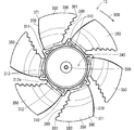
- FIG. 7 is a plan view of the oblique flow fan 13 when viewed from the front side thereof.
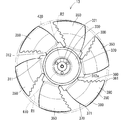
- FIG. 8 is a plan view of the oblique flow fan 13 when viewed from the rear side thereof.
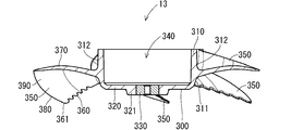
- FIG. 9 is a diagram showing a cross-sectional structure in arrow B1-B1 of FIG.
- FIG. 10 is a diagram showing a cross-sectional structure in arrow B2-B2 of FIG.
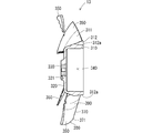
- FIG. 11 is a side view of the oblique flow fan 13 as viewed from the arrow B3 of FIG.
- the rotation direction 500 is shown in FIGS. 6 to 8.
- a plurality of blades 350 extend outward from the outer peripheral surface 311 of the peripheral wall portion 310 of the boss 300, and surround the outer peripheral surface 311 in the circumferential direction. There is. The front surface of the central portion of the flat plate portion 320 of the boss 300 is projected, and the convex portion 321 is formed in the central portion. The buried metal 330 is embedded in the convex portion 321. When the mixed flow fan 13 is viewed from the front side thereof, the mixed flow fan 13 rotates counterclockwise.
- the plurality of blades 350 and the boss 300 are integrally molded, but the manufacturing method of the mixed flow fan 13 is not limited to this.
- Each blade 350 has a substantially plate shape and has a shape in which two fan-shaped radii are curved in the rotation direction.
- Each blade 350 has a pair of main surfaces 390 facing each other, a front edge 360, a trailing edge 370, and an outer peripheral edge 380 connecting the front edge 360 and the trailing edge 370.
- the main surface 390 is inclined with respect to the axial direction so that the front edge 360 is located slightly forward and the trailing edge 370 is located slightly rearward.
- the shape of the front edge 360 is wavy as a measure against noise, but this is not the case.
- the inner space 340 of the boss 300 is, for example, a columnar shape.
- the outer shape of the boss 300 is generally a truncated cone shape in which a circle having a small diameter is located on the front side and a circle having a large diameter is located on the rear side.
- the outer peripheral surface 311 of the boss 300 has a truncated cone shape in which the diameter increases from the front side to the rear side.
- the outer peripheral surface 311 is partially recessed, so that it does not have a completely truncated cone shape.
- the portion of the outer peripheral surface 311 on the rear side (opening side of the boss 300) of the blade 350 is recessed, and the recess 312 is formed in the portion.
- the recess 312 prevents undercuts from occurring when the boss 300 and the plurality of blades 350 are molded using a mold.
- the recess 312 extends from the vicinity of the root of the blade 350 to the rear edge of the outer peripheral surface 311. A draft is formed on the wall surface 312a on the front edge 360 side of the recess 312.
- a plurality of recesses 313 are provided on the end surface on the opening side of the thick portion where the recesses 312 are not formed. These recesses 312 are so-called meat thefts and are provided to prevent sink marks from occurring during molding.
- FIG. 12 is a diagram showing a rotating surface 410 of the outer end 361 of the front edge 360 of the blade 350 and a rotating surface 420 of the outer end 371 of the outer end 370 of the trailing edge 370 of the blade 350. It can be said that the rotating surface 410 is the rotating surface at the front end of the outer peripheral edge 380 of the blade 350. It can be said that the rotating surface 420 is the rotating surface at the rear end of the outer peripheral edge 380. As shown in FIG. 12, the radius R1 of the rotating surface 410 is smaller than the radius R2 of the rotating surface 420. As a result, the wind pressure of the mixed flow fan 13 can be increased.
- the mixed flow fan 13 having the above structure draws air from the front side by rotating, and causes the drawn wind to flow backward. At this time, the mixed flow fan 13 causes the drawn wind to flow backward diagonally outward with respect to the axial direction.
- the fan device 10 of this example includes the mixed flow fan 13
- the wind pressure of the air exhausted from the fan device 10 can be improved.
- the fan device 10 can easily send the wind drawn into the inner 950 of the clothes 2 toward the exhaust ports (for example, cuffs and neck) of the clothes 2. Therefore, the body of the person wearing the clothes 2 can be appropriately cooled.
- the structure of the mixed flow fan 13 is not limited to the above example.
- the number of blades 350 may be other than six.
- the peripheral wall portion 310 of the boss 300 does not have to be provided with a plurality of recesses 313.
- the concave portion 312 is not formed on the outer peripheral surface 311 of the boss 300, and the outer shape of the boss 300 may be a completely truncated cone shape.
- the outer shape of the boss 300 may be cylindrical. Even in this case, by making the radius R1 of the rotating surface 410 smaller than the radius R2 of the rotating surface 420, the oblique flow fan 13 that sends the wind obliquely backward can be realized. Further, the radius R1 may be equal to or larger than the radius R2.
- the outer shape of the boss 300 of the oblique flow fan 13 is substantially truncated cone-shaped or completely truncated cone-shaped, the oblique flow fan 13 that sends wind diagonally backward is realized. Can be done.
- the fan device 10 has a plurality of wind pressure improving structures for improving the wind pressure in addition to the mixed flow fan 13. An example of each wind pressure improvement structure will be described below.
- the shape of the radial rib 280 on the exhaust side is set based on the air flow generated by the mixed flow fan 13.
- the radial direction rib 280 is slightly curved in the rotational direction from the peripheral end portion of the back surface portion 250 as shown in FIG. While reaching the tubular portion 260.
- the radial rib 280 extends along the axial direction in the tubular portion 260.
- each of the radial ribs 281,282 reaches the tubular portion 260 while being slightly curved in the rotational direction from the connection point with the outer circumferential rib 291.
- the radial rib 283 reaches the tubular portion 260 while being slightly curved in the rotational direction from the outer circumferential rib 292.
- Each of the radial ribs 283, 284, 285, 286 reaches the tubular portion 260 while being slightly curved in the rotational direction from the connection point with the outer circumferential rib 292.
- the radial rib 280 is curved in the rotational direction at the peripheral end portion of the back surface portion 250. As a result, when the air flowing along the rotation direction due to the rotation of the mixed flow fan 13 is exhausted from the vicinity of the peripheral end portion of the back surface portion 250, the radial rib 280 is less likely to obstruct the air flow. Therefore, the wind pressure of the air discharged from the fan device 10 can be improved.
- the shape of the peripheral wall portion 29 surrounding the mixed flow fan 13 in the housing 12 is set based on the air flow generated by the mixed flow fan 13.
- the inner corner of the peripheral wall portion 29 on the intake side has a chamfered shape. That is, the inner corner portion 212 on the intake side of the tubular portion 210 that forms a part of the peripheral wall portion 29 has a chamfered shape.
- the chamfered shape is a concept including a case where a slope is attached to a corner portion and a case where a corner portion is rounded.
- the inner corner portion 212 has a chamfered shape over the entire circumferential direction of the tubular portion 210. In this example, as shown in FIG. 5, a slope is provided on the inner corner portion 212 on the intake side of the tubular portion 210.
- the inner corner portion 212 may be rounded.
- the fan device 10 takes in air obliquely outside the outer diameter of the intake unit 200 (hereinafter, may be simply referred to as outside air) from the peripheral end portion 208 of the intake unit 200.
- outside air the outer air flow 600
- the peripheral wall portion 29 is less likely to obstruct the outer air flow 600 as shown in FIG. Therefore, the wind pressure of the air discharged from the fan device 10 can be improved.
- FIGS. 13 and 14 the cross-sectional structure of the fan device 10 is shown in a simplified manner. In FIGS. 13 and 14, the description of the fixing member 90 is omitted.
- the shape of the circumferential rib 204 of the intake portion 200 is set based on the air flow generated by the mixed flow fan 13.
- the three circumferential ribs 204 arranged concentrically may be referred to as the circumferential ribs 204a, 204b, and 204c in order from the inside.
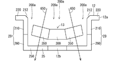
- FIG. 15 is a simplified view showing an example of the cross-sectional structure of the fan device 10 when the intake unit 200 does not have the rib structure 202 but is simply composed of openings.
- the description of the fixing member 90 is omitted.
- the intake portion 200 composed of the openings may be referred to as an intake opening 200a.
- the housing 12 is directed diagonally outward from the inner portion 209a of the intake opening 200a inside the peripheral end portion 208a, as shown by the arrow 650 in FIG. May go inside.
- the shape of the circumferential ribs 204a and 204b located inside the circumferential ribs 204c located at the peripheral end 208 of the intake portion 200 is housing from the intake portion 200 so as to be obliquely outward. It is set based on the flow of air entering the inside of 12. As a result, the air flow is less likely to be obstructed by the circumferential ribs 204a and 204b.
- the shapes of the circumferential ribs 204a and 204b will be described in detail below.
- FIG. 16 is an enlarged cross-sectional view of the portion A2 shown in FIG.
- each circumferential rib 204 has an outer wall surface 2041 and an inner wall surface 2042.
- the tip 2040 connected to the wall surfaces 2041 and 2042 is rounded.
- FIG. 17 is an enlarged view showing the cross-sectional shape of the circumferential rib 204a shown in FIG.
- FIG. 17 shows the cross-sectional shape of the circular rib 204a in the radial direction along the radial direction.
- the outer wall surface 2041 is located inside the virtual line 661.
- the wall surface 2041 is located closer to the central portion 205 of the intake portion 200 than the virtual line 661.
- the wall surface 2041 is gradually separated from the virtual line 661 from the edge 2041a toward the tip 2040. That is, the distance d1 between the wall surface 2041 and the virtual line 661 gradually increases from the edge 2041a toward the tip 2040.
- the inner wall surface 2042 is located outside the virtual line 662.
- the wall surface 2042 is located closer to the peripheral end portion 208 of the intake portion 200 than the virtual line 662.
- the wall surface 2042 is gradually separated from the virtual line 662 from the edge 2042a toward the tip 2040. That is, the distance between the wall surface 2042 and the virtual line 662 gradually increases from the edge 2042a toward the tip 2040.
- the wall surfaces 2041 and 2042 of the circumferential rib 204b have the same shape as the wall surfaces 2041 and 2042 of the circumferential rib 204a.
- the outer wall surface 2041 of the circumferential rib 204b is located inside the virtual line 661 extending along the axial direction passing through the end edge 2041a on the blade 350 side of the wall surface 2041.
- the wall surface 2041 of the circumferential rib 204b is gradually separated from the virtual line 661 from the edge 2041a toward the tip 2040.
- the wall surface 2042 inside the circumferential rib 204b is located outside the virtual line 662 extending along the axial direction passing through the end edge 2042a on the blade 350 side of the wall surface 2042.
- the wall surface 2042 of the circumferential rib 204b is gradually separated from the virtual line 662 from the edge 2042a toward the tip 2040.
- the wall surface 2041 of the circumferential rib 204a is located inside the virtual line 661.
- the circumferential rib 204a is less likely to obstruct the flow 651 of the air entering the housing 12 from the intake portion 200 so as to go diagonally outward. Therefore, the wind pressure of the air exhausted from the fan device 10 can be improved.
- the wall surface 2041 of the circumferential rib 204a is gradually separated from the virtual line 661 from the edge 2041a toward the tip 2040.
- the wall surface 2041 of the circumferential rib 204b is located inside the virtual line 661.
- the circumferential rib 204b is less likely to obstruct the flow 651 of the air entering the housing 12 from the intake portion 200 so as to go diagonally outward. Therefore, the wind pressure of the air exhausted from the fan device 10 can be improved.
- the wall surface 2041 of the circumferential rib 204b is gradually separated from the virtual line 661 from the edge 2041a toward the tip 2040, it is possible to realize the wall surface 2041 with small undulations or no undulations. Therefore, when the air is taken into the housing 12, the air pressure is less likely to decrease. As a result, the wind pressure of the air exhausted from the fan device 10 can be improved.
- the inner wall surface 2042 of the circumferential rib 204c located at the peripheral end portion 208 of the intake portion 200 has the same shape as the wall surface 2042 of the circumferential ribs 204a and 204b. Specifically, the wall surface 2042 of the circumferential rib 204c is located outside the virtual line 662 extending along the axial direction, passing through the edge of the wall surface 2042 on the blade 350 side, 2042a. The wall surface 2042 of the circumferential rib 204c is gradually separated from the virtual line 662 from the edge 2042a toward the tip 2040.
- the inner wall surface 2042 of the circumferential ribs 204a and 204b has the above-mentioned shape.
- the inner wall surface 2042 may have the same shape as the outer wall surface 2041.
- the outer wall surface 2042 of the circumferential rib 204a is located inside the virtual line 662.
- the wall surface 2042 is gradually separated from the virtual line 662 from the edge 2042a toward the tip 2040.
- the circumferential rib 204a is less likely to obstruct the flow 651 of the air entering the housing 12 from the intake portion 200 so as to go diagonally outward. Therefore, the wind pressure of the air exhausted from the fan device 10 can be further improved. Further, since the wall surface 2042 having small undulations or no undulations can be realized, the wind pressure of the air is less likely to decrease when the air is taken into the housing 12. As a result, the wind pressure of the air exhausted from the fan device 10 can be improved. Similarly, for the circumferential rib 204b, the inner wall surface 2042 may have the same shape as the outer wall surface 2041.
- the wall surface 2041 of the circumferential rib 204a is curved, but the shape of the wall surface 2041 of the circumferential rib 204a is not limited to this.
- the wall surface 2041 of the circumferential rib 204a may be an inclined plane that is inclined with respect to the axial direction 690.
- a wall surface 2041 having no undulations can be obtained.
- the wall surface 2041 of the circumferential rib 204a may be composed of a plurality of inclined planes 2041b that are inclined with respect to the axial direction 690. In the example of FIG.
- three inclined planes 2041b are arranged in order from the edge 2041a to the tip 2040.
- the inclination angles of the three inclined planes 2041b with respect to the axial direction 690 gradually decrease from the edge 2041a to the tip 2040.
- the shape of the wall surface 2041 of the circumferential rib 204b may be other than curved.
- the shape of the wall surface 2042 inside the circumferential rib 204a may be the same shape as the wall surface 2041 shown in FIG. 20, or may be the same shape as the wall surface 2041 shown in FIG. 21.
- the shape of the wall surface 2042 inside the circumferential rib 204b may be the same shape as the wall surface 2041 shown in FIG. 20, or may be the same shape as the wall surface 2041 shown in FIG. 21.
- the shapes of the wall surfaces 2041 of the circumferential ribs 204a and 204b are set based on the air flow generated by the oblique fan 13, but one of the wall surfaces 2041 of the circumferential ribs 204a and 204b. Only the shape may be set based on the air flow generated by the mixed flow fan 13. In this case, the other side of the wall surface 2041 of the circumferential ribs 204a and 204b may be a plane parallel to the axial direction 690.
- FIG. 22 is an enlarged cross-sectional view showing the portion A3 shown in FIG. FIG. 22 shows a cross section of the circumferential rib 291 included in the plurality of circumferential ribs 290.
- each circumferential rib 290 has an outer wall surface 2901 and an inner wall surface 2902.
- Each of the wall surfaces 2901 and 2902 is a plane that is substantially parallel to the axial direction.
- the tip 2900 connected to the wall surfaces 2901 and 2902 of each circumferential rib 290 is round.
- the shape of the circumferential rib 290 on the exhaust side may be set based on the air flow generated by the mixed flow fan 13, similarly to the shape of the circumferential rib 204 on the intake side.
- FIG. 23 is a diagram showing another example of the cross-sectional shape of the circumferential rib 290.
- FIG. 23 shows the cross-sectional shape of the circumferential rib 290 along the radial direction of the back surface portion 250.
- each of the outer wall surface 2901 and the inner wall surface 2902 of the circumferential rib 290 is set based on the air flow generated by the mixed flow fan 13.
- the outer wall surface 2901 is located outside the virtual line 665.
- the wall surface 2901 is located on the outer edge side of the back surface portion 250 with respect to the virtual line 665. Further, the wall surface 2901 is gradually separated from the virtual line 665 from the edge 2901a toward the tip 2900.
- FIG. 23 consider a virtual line 666 extending along the axial direction 690, passing through the edge 2902a on the blade 350 side of the inner wall surface 2902 of the circumferential rib 290.
- the inner wall surface 2902 is located outside the virtual line 666. Further, the wall surface 2902 is gradually separated from the virtual line 666 from the edge 2902a toward the tip 2900.
- the mixed flow fan 13 causes the drawn wind to flow diagonally outward with respect to the axial direction, air is discharged diagonally outward from the exhaust unit 25.
- the wall surface 2901 of the circumferential rib 290 is located outside the virtual line 665 along the axial direction 690, the air flow 652 discharged diagonally outward from the exhaust portion 25 is provided.
- the circumferential rib 290 is less likely to be blocked. Therefore, the wind pressure of the air exhausted from the fan device 10 can be improved.
- the wall surface 2902 of the circumferential rib 290 is located outside the virtual line 666, as shown in FIG. 23, the wall surface 2902 is circulated around the air flow 652 discharged diagonally outward from the exhaust portion 25.
- the directional rib 290 is less likely to be blocked. Therefore, the wind pressure of the air exhausted from the fan device 10 can be improved.
- the wall surface 2901 of the circumferential rib 290 is gradually separated from the virtual line 665 from the edge 2901a toward the tip 2900, it is possible to realize a wall surface 2901 with little undulations or no undulations. As a result, when the air flows along the wall surface 2901, the air flow is less likely to change. Therefore, when the air is discharged from the housing 12, the air pressure is less likely to decrease. As a result, the wind pressure of the air exhausted from the fan device 10 can be improved.
- the wall surface 2902 of the circumferential rib 290 is gradually separated from the virtual line 666 from the edge 2902a toward the tip 2900, it is possible to realize a wall surface 2902 with little undulations or no undulations. This makes it difficult for the air flow to change when the air flows along the wall surface 2902. Therefore, when the air is discharged from the housing 12, the air pressure is less likely to decrease. As a result, the wind pressure of the air exhausted from the fan device 10 can be improved.
- the shapes of the wall surfaces 2901 and 2902 of the circumferential rib 290 are set based on the air flow generated by the oblique flow fan 13, but the wall surfaces 2901 and 2902 of the circumferential rib 290 are set. Only one shape may be set based on the air flow generated by the mixed flow fan 13. In this case, the other of the wall surfaces 2901 and 2902 of the circumferential rib 290 may be a plane parallel to the axial direction 690, as shown in FIG.
- a part or all of the shapes of the plurality of circumferential ribs 290 included in the exhaust unit 25 may be set based on the air flow generated by the mixed flow fan 13.
- the wall surface 2901 is an inclined plane inclined with respect to the axial direction 690, but may have another shape.
- the wall surface 2901 may be curved in the same manner as the wall surface 2041 shown in FIG. 18 above.
- the wall surface 2901 may be composed of a plurality of inclined planes, similarly to the wall surface 2041 shown in FIG. 21 above.
- the wall surface 2902 may have a shape other than the shape shown in FIG. 23.
- the wall surface 2902 may be curved, similar to the wall surface 2041 shown in FIG.
- the wall surface 2902 may be composed of a plurality of inclined planes as in the wall surface 2041 shown in FIG.
- the fan device 10 is provided with the first to third wind pressure improving structures, but other wind pressure improving structures may be provided.
- the fan device 10 may include a fourth wind pressure improving structure described below.
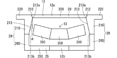
- the housing 12 has a truncated cone-shaped inner peripheral surface whose diameter on the intake side is smaller than the diameter on the exhaust side, which surrounds the plurality of blades 350 along the rotation direction.
- the peripheral wall portion 29 that surrounds the plurality of blades 350 along the rotation direction has a truncated cone-shaped inner peripheral surface whose diameter on the intake side is smaller than the diameter on the exhaust side.
- FIG. 24 is a simplified view showing an example of the cross-sectional structure of the fan device 10 according to this example.
- the description of the fixing member 90 is omitted.
- the tubular portion 210 forming a part of the peripheral wall portion 29 has a truncated cone-shaped inner peripheral surface 213 whose diameter on the intake side is smaller than the diameter on the exhaust side.
- the diameter of the circular edge 213a on the intake side of the inner peripheral surface 213 is smaller than the diameter of the circular edge 213b on the exhaust side of the inner peripheral surface 213.
- the edge 213a on the intake side is connected to the inner corner portion 212 having a chamfered shape.
- the inclination angle ⁇ of the truncated cone-shaped inner peripheral surface 213 is set within a predetermined range of the reference angle ⁇ described later, which is determined by the shape of the blade 350, for example.
- the inclination angle ⁇ is set within ⁇ 10% of the reference angle ⁇ , for example.
- FIG. 25 is a diagram for explaining the reference angle ⁇ .
- FIG. 25 schematically shows the mixed flow fan 13.
- the tilt angle ⁇ of the truncated cone 700 (specifically, the tilt angle ⁇ of the side surface of the truncated cone 700) is set as the reference angle ⁇ .
- the inclination angle ⁇ of the inner peripheral surface 213 of the housing 12 is set to, for example, 0.9 times or more the inclination angle ⁇ and 1.1 times or less the inclination angle ⁇ .
- the relationship between the tilt angle ⁇ and the reference angle ⁇ is not limited to this example.
- the housing 12 has a truncated cone-shaped inner peripheral surface 213 whose diameter on the intake side is smaller than the diameter on the exhaust side, which surrounds the plurality of blades 350 along the rotation direction. ..
- the inner peripheral surface of the housing 12 can be brought closer to the outer peripheral edge 380 of each blade 350, and the gap between the inner peripheral surface of the housing 12 and the plurality of blades 350 can be reduced.
- the wind pressure of the air exhausted from the fan device 10 can be improved.
- the fan device 10 may include only a part of the above-mentioned first to fourth wind pressure improving structures. That is, the fan device 10 may include at least one of the first to fourth wind pressure improving structures.
- the garment with a fan 1 and the fan device 10 have been described in detail, but the above description is an example in all aspects, and the disclosure is not limited thereto.
- the various examples described above can be applied in combination as long as they do not contradict each other. And it is understood that innumerable examples not illustrated can be assumed without departing from the scope of this disclosure.
Landscapes
- Engineering & Computer Science (AREA)
- Mechanical Engineering (AREA)
- General Engineering & Computer Science (AREA)
- Environmental & Geological Engineering (AREA)
- Health & Medical Sciences (AREA)
- General Health & Medical Sciences (AREA)
- Physical Education & Sports Medicine (AREA)
- Textile Engineering (AREA)
- Structures Of Non-Positive Displacement Pumps (AREA)
Priority Applications (1)
| Application Number | Priority Date | Filing Date | Title |
|---|---|---|---|
| JP2021567548A JPWO2021132353A1 (https=) | 2019-12-26 | 2020-12-23 |
Applications Claiming Priority (2)
| Application Number | Priority Date | Filing Date | Title |
|---|---|---|---|
| JP2019236587 | 2019-12-26 | ||
| JP2019-236587 | 2019-12-26 |
Publications (1)
| Publication Number | Publication Date |
|---|---|
| WO2021132353A1 true WO2021132353A1 (ja) | 2021-07-01 |
Family
ID=76576126
Family Applications (1)
| Application Number | Title | Priority Date | Filing Date |
|---|---|---|---|
| PCT/JP2020/048210 Ceased WO2021132353A1 (ja) | 2019-12-26 | 2020-12-23 | 衣服用ファン装置及びファン付き衣服 |
Country Status (2)
| Country | Link |
|---|---|
| JP (1) | JPWO2021132353A1 (https=) |
| WO (1) | WO2021132353A1 (https=) |
Citations (8)
| Publication number | Priority date | Publication date | Assignee | Title |
|---|---|---|---|---|
| JPH01159498A (ja) * | 1987-12-14 | 1989-06-22 | Mitsubishi Electric Corp | 送風装置 |
| JPH0640318U (ja) * | 1992-11-05 | 1994-05-27 | 株式会社小松製作所 | 吸い込みファン用ラジエータ冷却装置 |
| JPH11182487A (ja) * | 1997-12-18 | 1999-07-06 | Daikin Ind Ltd | 携帯型人体熱交換装置 |
| JPH11354964A (ja) * | 1998-06-10 | 1999-12-24 | Nec Corp | 電気機器 |
| JP2004183649A (ja) * | 2002-11-22 | 2004-07-02 | Nippon Densan Corp | ファンモータ、電子または電気機器の筐体、及び電子または電気機器 |
| JP2005054299A (ja) * | 2003-08-01 | 2005-03-03 | Seft Dev Lab Co Ltd | 冷却衣服 |
| JP2006018262A (ja) * | 2004-06-30 | 2006-01-19 | Taida Electronic Ind Co Ltd | ファン |
| WO2019142572A1 (ja) * | 2018-01-18 | 2019-07-25 | 株式会社マキタ | 送風装置および衣服 |
-
2020
- 2020-12-23 JP JP2021567548A patent/JPWO2021132353A1/ja active Pending
- 2020-12-23 WO PCT/JP2020/048210 patent/WO2021132353A1/ja not_active Ceased
Patent Citations (8)
| Publication number | Priority date | Publication date | Assignee | Title |
|---|---|---|---|---|
| JPH01159498A (ja) * | 1987-12-14 | 1989-06-22 | Mitsubishi Electric Corp | 送風装置 |
| JPH0640318U (ja) * | 1992-11-05 | 1994-05-27 | 株式会社小松製作所 | 吸い込みファン用ラジエータ冷却装置 |
| JPH11182487A (ja) * | 1997-12-18 | 1999-07-06 | Daikin Ind Ltd | 携帯型人体熱交換装置 |
| JPH11354964A (ja) * | 1998-06-10 | 1999-12-24 | Nec Corp | 電気機器 |
| JP2004183649A (ja) * | 2002-11-22 | 2004-07-02 | Nippon Densan Corp | ファンモータ、電子または電気機器の筐体、及び電子または電気機器 |
| JP2005054299A (ja) * | 2003-08-01 | 2005-03-03 | Seft Dev Lab Co Ltd | 冷却衣服 |
| JP2006018262A (ja) * | 2004-06-30 | 2006-01-19 | Taida Electronic Ind Co Ltd | ファン |
| WO2019142572A1 (ja) * | 2018-01-18 | 2019-07-25 | 株式会社マキタ | 送風装置および衣服 |
Also Published As
| Publication number | Publication date |
|---|---|
| JPWO2021132353A1 (https=) | 2021-07-01 |
Similar Documents
| Publication | Publication Date | Title |
|---|---|---|
| US20160290352A1 (en) | Impeller and blower | |
| JP3226224U (ja) | 過給式空調服 | |
| CN212803748U (zh) | 送风装置和衣服 | |
| US20160290358A1 (en) | Centrifugal fan | |
| JP3993118B2 (ja) | 二重反転式軸流送風機 | |
| JPWO2016068280A1 (ja) | 送風装置および掃除機 | |
| CN106062380B (zh) | 送风装置 | |
| BR102014024689A2 (pt) | conjunto de ventilação | |
| US7891942B2 (en) | Centrifugal blower | |
| JP6560433B1 (ja) | ファン付き衣服用ファンユニット | |
| JP2020020320A (ja) | インペラ、遠心ファン | |
| CN102536860A (zh) | 一种具有出风增压果的薄型横流式风扇 | |
| WO2021132353A1 (ja) | 衣服用ファン装置及びファン付き衣服 | |
| US10495114B2 (en) | Blower | |
| TWI401365B (zh) | An electric blower, an electric vacuum cleaner loaded with the electric blower, and a method of manufacturing the same | |
| JP6568707B2 (ja) | 送風装置および空気流通式衣服 | |
| CN113803291A (zh) | 非对称双出风口离心扇 | |
| CN107208662A (zh) | 送风装置 | |
| JP6686509B2 (ja) | 送風装置およびこれを備えた給湯装置 | |
| JP2019090342A (ja) | ブロワ装置 | |
| JPH09164014A (ja) | ヘアードライヤ | |
| JP6690603B2 (ja) | 遠心送風機 | |
| JP2701603B2 (ja) | 遠心送風機 | |
| CN216599192U (zh) | 后罩结构及电机 | |
| CN205225796U (zh) | 风扇 |
Legal Events
| Date | Code | Title | Description |
|---|---|---|---|
| 121 | Ep: the epo has been informed by wipo that ep was designated in this application |
Ref document number: 20905859 Country of ref document: EP Kind code of ref document: A1 |
|
| ENP | Entry into the national phase |
Ref document number: 2021567548 Country of ref document: JP Kind code of ref document: A |
|
| NENP | Non-entry into the national phase |
Ref country code: DE |
|
| 122 | Ep: pct application non-entry in european phase |
Ref document number: 20905859 Country of ref document: EP Kind code of ref document: A1 |