WO2021132041A1 - 支持体および表示装置 - Google Patents
支持体および表示装置 Download PDFInfo
- Publication number
- WO2021132041A1 WO2021132041A1 PCT/JP2020/047296 JP2020047296W WO2021132041A1 WO 2021132041 A1 WO2021132041 A1 WO 2021132041A1 JP 2020047296 W JP2020047296 W JP 2020047296W WO 2021132041 A1 WO2021132041 A1 WO 2021132041A1
- Authority
- WO
- WIPO (PCT)
- Prior art keywords
- base
- support
- display unit
- mounting portion
- installation state
- Prior art date
- Legal status (The legal status is an assumption and is not a legal conclusion. Google has not performed a legal analysis and makes no representation as to the accuracy of the status listed.)
- Ceased
Links
Images


Classifications
-
- G—PHYSICS
- G02—OPTICS
- G02F—OPTICAL DEVICES OR ARRANGEMENTS FOR THE CONTROL OF LIGHT BY MODIFICATION OF THE OPTICAL PROPERTIES OF THE MEDIA OF THE ELEMENTS INVOLVED THEREIN; NON-LINEAR OPTICS; FREQUENCY-CHANGING OF LIGHT; OPTICAL LOGIC ELEMENTS; OPTICAL ANALOGUE/DIGITAL CONVERTERS
- G02F1/00—Devices or arrangements for the control of the intensity, colour, phase, polarisation or direction of light arriving from an independent light source, e.g. switching, gating or modulating; Non-linear optics
- G02F1/01—Devices or arrangements for the control of the intensity, colour, phase, polarisation or direction of light arriving from an independent light source, e.g. switching, gating or modulating; Non-linear optics for the control of the intensity, phase, polarisation or colour
- G02F1/13—Devices or arrangements for the control of the intensity, colour, phase, polarisation or direction of light arriving from an independent light source, e.g. switching, gating or modulating; Non-linear optics for the control of the intensity, phase, polarisation or colour based on liquid crystals, e.g. single liquid crystal display cells
- G02F1/133—Constructional arrangements; Operation of liquid crystal cells; Circuit arrangements
- G02F1/1333—Constructional arrangements; Manufacturing methods
- G02F1/133308—Support structures for LCD panels, e.g. frames or bezels
-
- G—PHYSICS
- G09—EDUCATION; CRYPTOGRAPHY; DISPLAY; ADVERTISING; SEALS
- G09F—DISPLAYING; ADVERTISING; SIGNS; LABELS OR NAME-PLATES; SEALS
- G09F9/00—Indicating arrangements for variable information in which the information is built-up on a support by selection or combination of individual elements
-
- H—ELECTRICITY
- H04—ELECTRIC COMMUNICATION TECHNIQUE
- H04N—PICTORIAL COMMUNICATION, e.g. TELEVISION
- H04N5/00—Details of television systems
- H04N5/64—Constructional details of receivers, e.g. cabinets or dust covers
-
- H—ELECTRICITY
- H05—ELECTRIC TECHNIQUES NOT OTHERWISE PROVIDED FOR
- H05K—PRINTED CIRCUITS; CASINGS OR CONSTRUCTIONAL DETAILS OF ELECTRIC APPARATUS; MANUFACTURE OF ASSEMBLAGES OF ELECTRICAL COMPONENTS
- H05K5/00—Casings, cabinets or drawers for electric apparatus
- H05K5/0017—Casings, cabinets or drawers for electric apparatus with operator interface units
- H05K5/0018—Casings, cabinets or drawers for electric apparatus with operator interface units having an electronic display
-
- H—ELECTRICITY
- H05—ELECTRIC TECHNIQUES NOT OTHERWISE PROVIDED FOR
- H05K—PRINTED CIRCUITS; CASINGS OR CONSTRUCTIONAL DETAILS OF ELECTRIC APPARATUS; MANUFACTURE OF ASSEMBLAGES OF ELECTRICAL COMPONENTS
- H05K5/00—Casings, cabinets or drawers for electric apparatus
- H05K5/02—Details
- H05K5/0204—Mounting supporting structures on the outside of casings
-
- H—ELECTRICITY
- H05—ELECTRIC TECHNIQUES NOT OTHERWISE PROVIDED FOR
- H05K—PRINTED CIRCUITS; CASINGS OR CONSTRUCTIONAL DETAILS OF ELECTRIC APPARATUS; MANUFACTURE OF ASSEMBLAGES OF ELECTRICAL COMPONENTS
- H05K5/00—Casings, cabinets or drawers for electric apparatus
- H05K5/02—Details
- H05K5/0217—Mechanical details of casings
- H05K5/0234—Feet; Stands; Pedestals, e.g. wheels for moving casing on floor
Definitions
- the present disclosure relates to a support that supports the display unit, and a display device including the display unit and the support.
- a support capable of selecting the support form of the display unit according to the user's application, preference, installation environment, etc., and a display device provided with such a support and the display unit.
- the support according to the embodiment of the present disclosure has a display surface extending in the horizontal direction and the vertical direction, respectively, and has a center position in the horizontal direction and a first end located on opposite sides of the center position in the horizontal direction.
- a display unit having an edge and a second edge edge is supported so as to be erected on a mounting surface, and has a first support unit and a second support unit.
- the first support unit is detachably provided with respect to the display unit.
- the second support unit is removable from the display unit and is provided as a separate body from the first support unit.
- the support as one embodiment of the present disclosure is configured so that the first form and the second form can be selected.
- the first support unit is attached to the first position between the center position in the horizontal direction and the first edge of the display unit, and the center position in the horizontal direction of the display unit.
- a second support unit is mounted in a second position between the and the second edge.
- the second support unit is attached to the first position or the third position between the center position in the horizontal direction and the first edge of the display unit, and the display unit is of the display unit.
- the first support unit is mounted at a second position or at a fourth position between the center position in the horizontal direction and the second edge.
- FIG. 3 is a top view of the display device shown in FIG. 1A as viewed from above. It is a front view which shows the whole structure example in the 2nd installation state of the display device which concerns on 1st Embodiment of this disclosure. It is a top view of the display device shown in FIG. 2A as viewed from above. It is a rear view which represented the back surface of the display unit shown in FIG. 1A schematically. It is a 1st rear view which shows the example of the structure of the main part of the back surface in the display device shown in FIG. 1A.
- FIG. 3 is a top view of the display device shown in FIG. 1A as viewed from above. It is a front view which shows the whole structure example in the 2nd installation state of the display device which concerns on 1st Embodiment of this disclosure. It is a top view of the display device shown in FIG. 2A as viewed from above. It is a rear view which represented the back surface of the display unit shown in FIG. 1A schematically. It is a 1
- FIG. 2 is a second rear view showing an example of a configuration of a main part on the back surface of the display device shown in FIG. 1A.
- FIG. 2 is a first rear view showing an example of a configuration of a main part on the back surface of the display device shown in FIG. 2A.
- 2 is a second rear view showing an example of a configuration of a main part on the back surface of the display device shown in FIG. 2A.
- It is a perspective view which shows the detail of the 2nd support unit shown in FIG. 4B.
- 6 is a first schematic view showing the postures of the first support unit and the second support unit shown in FIGS. 6A and 6B with respect to the mounting surface.
- FIG. 6 is a second schematic view showing the postures of the first support unit and the second support unit shown in FIGS. 6A and 6B with respect to the mounting surface. It is a front view which shows the whole structure example in the 1st installation state of the display device which concerns on 2nd Embodiment of this disclosure.
- FIG. 8 is a top view of the display device shown in FIG. 8A as viewed from above. It is a front view which shows the whole structure example in the 2nd installation state of the display device which concerns on 1st Embodiment of this disclosure.
- 9 is a top view of the display device shown in FIG. 9A as viewed from above. It is a perspective view which shows the detail of the 1st support unit shown in FIG. 8A.
- FIG. 8A It is a perspective view which shows the detail of the 2nd support unit shown in FIG. 8A. It is a front view which shows the whole structure example in the 1st installation state of the display device which concerns on 3rd Embodiment of this disclosure. It is a top view of the display device shown in FIG. 11A as viewed from above. It is a front view which shows the whole structure example in the 2nd installation state of the display device which concerns on 3rd Embodiment of this disclosure. It is the top view which looked at the display device shown in FIG. 12A from above.
- FIG. 11A is an enlarged rear view showing an enlarged view of a first mounting portion provided on the back surface of the display unit shown in FIG. 11A.
- FIG. 11A is an enlarged rear view showing an enlarged view of a first mounting portion provided on the back surface of the display unit shown in FIG. 11A.
- FIG. 11A is an enlarged rear view showing an enlarged view of a second mounting portion provided on the back surface of the display unit shown in FIG. 11A.
- FIG. 11A is a rear view showing an enlarged view of the first support unit and its vicinity in the display device of the first installation state shown in FIG. 11A.
- FIG. 12A is a rear view showing an enlarged view of the first support unit and its vicinity in the display device of the second installed state shown in FIG. 12A.
- FIG. 11A is a rear view showing an enlarged view of the second support unit in the first installation state display device shown in FIG. 11A and its vicinity. It is a rear view which enlarges and shows the 2nd support unit in the 2nd installation state display device shown in FIG. 12A, and the vicinity thereof.
- FIG. 14A It is an exploded perspective view of the 1st support unit shown in FIG. 14A. It is an exploded perspective view of the 2nd support unit shown in FIG. 15A. It is a front view which shows the whole structure example in the 1st installation state of the display device which concerns on 4th Embodiment of this disclosure. It is a top view of the display device shown in FIG. 17A as viewed from above. It is a front view which shows the whole structure example in the 2nd installation state of the display device which concerns on 4th Embodiment of this disclosure.
- FIG. 8 is a top view of the display device shown in FIG. 18A as viewed from above. It is a perspective view of the display device shown in FIG. 17A viewed obliquely from the front.
- FIG. 17A is a rear view of the first support unit shown in FIG. 17A as viewed from the rear.
- FIG. 18A is a rear view of the first support unit shown in FIG. 18A as viewed from the rear.
- FIG. 17A is a partially enlarged perspective view showing a positional relationship between a part of the first support unit and the neck shown in FIG. 17A.
- FIG. 8 is a partially enlarged perspective view showing a positional relationship between a part of the first support unit and the neck shown in FIG. 18A.
- FIG. 18A is a partially enlarged perspective view showing a positional relationship between a part of the first support unit and the neck shown in FIG. 18A.
- FIG. 17A is a rear view of the second support unit shown in FIG. 17A as viewed from the rear. It is a rear view which looked at the 2nd support unit shown in FIG. 18A from the back. It is a rear view which looked at the 2nd support unit shown in FIG. 18A from the back. It is an exploded perspective view which shows the detail of the 2nd support unit shown in FIG. 18A.
- FIG. 17A is a partially enlarged perspective view showing a positional relationship between a part of the second support unit and the neck shown in FIG. 17A.
- FIG. 8 is a partially enlarged perspective view showing a positional relationship between a part of the second support unit and the neck shown in FIG. 18A.
- FIG. 6 is a top view of the display device shown in FIG. 26A as viewed from above. It is a front view which shows the whole structure example in the 4th installation state of the display device which concerns on 4th Embodiment of this disclosure. It is a top view of the display device shown in FIG. 27A as viewed from above.
- FIG. 26A is a rear view of the first support unit shown in FIG. 26A as viewed from the rear.
- FIG. 26B is a rear view of the second support unit shown in FIG. 26B as viewed from the rear. It is a rear view which looked at the 2nd support unit shown in FIG. 27A from the back.
- FIG. 27B is a rear view of the first support unit shown in FIG. 27B as viewed from the rear.
- First Embodiment A first example of a display device comprising a stand having a pair of support units capable of varying horizontal spacing. 2.
- Second Embodiment A second example of a display device comprising a stand with a pair of support units capable of varying horizontal spacing. 3.
- Third Embodiment A first example of a display device including a stand having a pair of support units capable of changing the height position of the display unit in the vertical direction. 4.
- FIG. 1A and 1B show an example of the overall configuration of the display device 100 as the first embodiment of the present disclosure in the first installation state.
- FIG. 1A is a front view of the display device 100 in the first installed state as viewed from the front (viewer side)
- FIG. 1B is a top view of the display device 100 in the first installed state as viewed from above. ..
- FIG. 2A and 2B show an example of the overall configuration of the display device 100 in the second installation state.
- FIG. 2A is a front view of the display device 100 in the second installed state as viewed from the front (viewer side)
- FIG. 2B is a top view of the display device 100 in the second installed state as viewed from above. ..
- the display device 100 includes a display unit 1 and a stand 2 as a support for supporting the display unit 1 on the mounting surface FS. It is also a so-called stationary display device.
- the mounting surface FS is a horizontal surface such as a floor surface, a shelf surface, or a top surface of a table.
- the display unit 1 includes, for example, a display panel 11 including a display surface 1A for displaying an image toward the front, and a main body 12 holding the display panel 11.
- the display surface 1A is a horizontally long rectangular screen that spreads in the horizontal direction and the vertical direction, respectively, and has a first edge 1R and a second edge 1L located on opposite sides of the center position CP in the horizontal direction.
- the horizontal direction is the X-axis direction
- the vertical direction is the Y-axis direction
- the front-rear direction intersecting the display surface 1A is the Z-axis direction.
- the display panel 11 is, for example, a liquid crystal display device including a liquid crystal layer, an organic EL display device including an organic EL element, or the like.
- the main body 12 is a housing that holds, for example, a display panel 11 and a circuit board provided with a drive circuit, an image processing circuit, or the like for driving the display panel 11.
- the main body 12 includes a back surface 1B on the opposite side of the display surface 1A, and two mounting portions on the left and right sides are provided on the lower portion of the back surface 1B, for a total of four mounting portions.
- the main body 12 has outer mounting portions 13L and 13R provided near the horizontal ends of the display panel 11, and inner mounting portions 14L and 14L provided between the outer mounting portions 13L and 13R, respectively. It has 14R.
- FIG. 3 is a rear view schematically showing the back surface 1B of the display unit 1. In FIG. 3, the stand 2 is not shown.
- the stand 2 has a first support unit 2A and a second support unit 2B.
- the first support unit 2A and the second support unit 2B are provided as separate bodies from each other, and both are provided detachably from the display unit 1.
- the first support unit 2A In the first installation state (FIGS. 1A and 1B), the first support unit 2A has an outer mounting portion 13R (of the display unit 1) between the center position CP in the X-axis direction and the first edge 1R. It can be attached to the first position).
- the first support unit 2A In the second installation state (FIGS. 2A and 2B), the first support unit 2A has an inner mounting portion 14L (inside mounting portion 14L) between the center position CP in the X-axis direction and the second edge 1L of the display unit 1. It can be attached to the 4th position). More specifically, as shown in FIGS. 4A and 5A, the first support unit 2A includes a neck 20A as a first mounting portion detachably formed on the display unit 1 and a mounting surface FS.
- the neck 20A, the arm 22A, and the plate-shaped member 23A of the first support unit 2A can be manufactured by bending one sheet metal member such as stainless steel or by casting.
- the first support unit 2A may be formed by individually molding a plurality of members and then joining them by welding or the like.
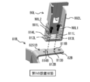
- FIG. 4A is an enlarged perspective view showing the first support unit 2A attached to the outer attachment portion 13R and its vicinity in an enlarged manner in the first installation state.
- FIG. 5A is an enlarged perspective view showing the first support unit 2A attached to the inner mounting portion 14L and its vicinity in an enlarged manner in the second installation state.
- the second support unit 2B In the first installation state (FIGS. 1A and 1B), the second support unit 2B has an outer mounting portion 13L (of the display unit 1) between the center position CP in the X-axis direction and the second edge 1L. It can be attached to the second position). In the second installation state (FIGS. 2A and 2B), the second support unit 2B has an inner mounting portion 14R (inside mounting portion 14R) between the center position CP in the X-axis direction and the first edge 1R of the display unit 1. It can be attached to the third position). Therefore, in the first installation state and the second installation state, the positional relationship between the first support unit 2A and the second support unit 2B in the left-right direction is opposite. More specifically, as shown in FIGS.
- the second support unit 2B includes a neck 20B as a second mounting portion detachably formed on the display unit 1 and a mounting surface FS. It has a base 21B as a second base to be in contact with the neck 20B and an arm 22B connecting the neck 20B and the base 21B.
- the neck 20B and the plate-shaped member 23B (described later) of the base 21B are integrally formed via the arm 22B.
- the neck 20B, the arm 22B, and the plate-shaped member 23B of the second support unit 2B can be manufactured by bending one sheet metal member such as stainless steel or by casting.
- the second support unit 2B may be formed by individually molding a plurality of members and then joining them by welding or the like.
- the elastic member 24B and the cover 25B which will be described later, may be manufactured separately from the plate-shaped member 23B and attached to the plate-shaped member 23B in a separate process.
- FIG. 4B is an enlarged perspective view showing the second support unit 2B mounted on the outer mounting portion 13L in the first installation state and its vicinity in an enlarged manner.
- FIG. 5B is an enlarged perspective view showing the second support unit 2B mounted on the inner mounting portion 14R and its vicinity in an enlarged manner in the second installation state.
- the first installation posture of the base 21A and the base 21B in the first installation state (FIGS. 4A and 4B) with respect to the mounting surface FS and the second installation posture and the second The second installation postures of the base 21A and the base 21B in the installation state (FIGS. 5A and 5B) with respect to the mounting surface FS are different. That is, in the display device 100, the first support unit 2A and the second support unit 2B in the first installation state can be changed to the second installation state by rotating each of them by approximately 90 °. On the contrary, in the display device 100, the first support unit 2A and the second support unit 2B in the second installation state can be changed to the first installation state by rotating each of them by approximately 90 °.
- the distance D1A (FIG. 1B) between the base 21A and the center position CP in the first installation state is longer than the distance D2A (FIG. 2B) between the base 21A and the center position CP in the second installation state. ..
- the distance D1B (FIG. 1B) between the base 21B and the center position CP in the first installation state is longer than the distance D2B (FIG. 2B) between the base 21B and the center position CP in the second installation state. That is, in the first installation state, the base 21A and the base 21B are located farther from the center position CP in the X-axis direction as compared with the second installation state. From the viewpoint of improving support stability, it is desirable that the distance D1A and the distance D1B are equal in the first installation state, and it is desirable that the distance D2A and the distance D2B are equal in the second installation state.
- the neck 20A is mounted on the outside so that at least a part of the base 21A protrudes to the side opposite to the center position CP (that is, outside the display surface 1A) when viewed from the first edge 1R.
- the neck 20B is attached to the outer attachment portion 13L so that at least a part of the base 21B protrudes from the second end edge 1L on the side opposite to the center position CP (that is, outside the display surface 1A).
- the neck 20A is attached to the inner mounting portion 14L so that the base 21A fits between the first edge 1R and the center position CP, and the base 21B is centered with the second edge 1L.
- the neck 20B is attached to the inner attachment portion 14R so as to fit between the position CP and the position CP.
- FIG. 6A shows an overall configuration example of the first support unit 2A.
- the neck 20A has holes 261A to 263A through which the screws NA1 to NA3 (see FIGS. 4A and 5A) are inserted at positions at the vertices of the triangles, respectively.
- the neck 20A is fastened to the outer mounting portion 13R or the inner mounting portion 14L by screws NA1 to NA3 (see FIGS. 4A and 5A).
- FIG. 6B shows an overall configuration example of the second support unit 2B. As shown in FIG. 6B, the neck 20B has holes 261B to 263B through which the screws NB1 to NB3 (see FIGS.
- the neck 20B is fastened to the outer mounting portion 13L or the inner mounting portion 14R by screws NB1 to NB3 (see FIGS. 4B and 5B).
- the neck 20A In the first installation state, the neck 20A is fixed to the outer mounting portion 13R in a posture in which the screws NA1 and NA3 and the screws NA2 are separated from each other in the Y-axis direction (FIG. 4A). In the second installation state, the neck 20A is fixed to the inner mounting portion 14L in a posture in which the screws NA2 and NA3 and the screws NA1 are separated from each other in the Y-axis direction (FIG. 5A). In the first installation state, the neck 20B is fixed to the outer mounting portion 13L in a posture in which the screws NB1 and NB3 and the screws NB2 are separated from each other in the Y-axis direction (FIG. 4B).
- the neck 20B is fixed to the inner mounting portion 14R in a posture in which the screws NB2 and NB3 and the screws NB1 are separated from each other in the Y-axis direction (FIG. 5B). Therefore, even when the stand 2 is miniaturized, it is possible to prevent the display unit 1 from tilting in the front-rear direction (Z-axis direction) in both the first installation state and the second installation state.
- the necks 20A and 20B may be fixed to the display unit 1 at four or more locations.
- the neck 20A is provided with an opening 27A1 including a round hole portion 271A and a long hole portion 272A, and a notch 27A2.
- two screws 15R1 and 15R2 are erected on the outer mounting portion 13R.
- the screw 15R1 engages with the elongated hole portion 272A of the opening 27A1 and the screw 15R2 engages with the notch 27A2, so that the first support unit 2A is attached to the outside in the stage before fastening the neck 20A with the screws NA1 to NA3. It is temporarily fixed to the portion 13R.
- the screw 15R1 is inserted into the round hole portion 271A of the opening 27A1 and then slides into and engages with the elongated hole portion 272A.
- two screws 16L1 and 16L2 are erected on the inner mounting portion 14L.
- the screw 16L1 engages with the elongated hole portion 272A of the opening 27A1, and the screw 16L2 engages with the notch 27A2, so that the first support unit 2A is internally mounted in the stage before fastening the neck 20A with the screws NA1 to NA3. It is temporarily fixed to the portion 14L.
- the screw 16L1 is inserted into the round hole portion 271A of the opening 27A1 and then slides into and engages with the elongated hole portion 272A.
- the neck 20B is provided with an opening 27B1 including a round hole portion 271B and a long hole portion 272B, and a notch 27B2.
- two screws 15L1 and 15L2 are erected on the outer mounting portion 13L.
- the screw 15L1 engages with the elongated hole portion 272B of the opening 27B1 and the screw 15LR2 engages with the notch 27B2, so that the second support unit 2B is attached to the outside in the stage before fastening the neck 20B with the screws NB1 to NB3. It is temporarily fixed to the portion 13L.
- the screw 15L1 is inserted into the round hole portion 271B of the opening 27B1 and then slides into and engages with the elongated hole portion 272B.
- two screws 16R1 and 16R2 are erected on the inner mounting portion 14R.
- the screw 16R1 engages with the elongated hole portion 272B of the opening 27B1 and the screw 16R2 engages with the notch 27B2, so that the second support unit 2B is internally mounted in the stage before fastening the neck 20B with the screws NB1 to NB3. It is temporarily fixed to the portion 14R.
- the screw 16R1 is inserted into the round hole portion 271B of the opening 27B1 and then slides into and engages with the elongated hole portion 272B.
- the base 21A of the first support unit 2A extends in the Z-axis direction intersecting the display surface 1A, for example, and includes the plate-shaped member 23A and the elastic member 24A. , With a cover 25A.
- the plate-shaped member 23A is made of a high-strength material such as stainless steel, and is connected to the end of the arm 22A opposite to the neck 20A.
- the elastic member 24A is made of an elastic material such as rubber, and is attached to the plate-shaped member 23A on the side opposite to the arm 22A.
- the elastic member 24A has, for example, a flat plate shape, and is, for example, adhesively fixed to the plate-shaped member 23A.
- the elastic member 24A comes into contact with the mounting surface FS in both the first installation state (FIGS. 1A and 1B) and the second installation state (FIGS. 2A and 2B).
- the cover 25A is a member that covers the elastic member 24A, and is provided to be detachably attached to the elastic member 24A.
- the cover 25A is attached so as to cover the elastic member 24A in the first installation state, and is removed in the second installation state.
- the base 21B of the second support unit 2B extends in the Z-axis direction, for example, and has a plate-shaped member 23B, an elastic member 24B, and a cover 25B. And have.
- the plate-shaped member 23B is made of a high-strength material such as stainless steel, and is connected to the end of the arm 22B opposite to the neck 20B.
- the elastic member 24B is made of an elastic material such as rubber, and is attached to the plate-shaped member 23B on the side opposite to the arm 22B.
- the elastic member 24B has, for example, a flat plate shape, and is, for example, adhesively fixed to the plate-shaped member 23B.
- the elastic member 24B comes into contact with the mounting surface FS in both the first installation state (FIGS. 1A and 1B) and the second installation state (FIGS. 2A and 2B).
- the cover 25B is a member that covers the elastic member 24B, and is provided to be detachably attached to the elastic member 24B.
- the cover 25B is attached so as to cover the elastic member 24B in the first installation state, and is removed in the second installation state.
- FIG. 7A is a schematic view showing an enlarged positional relationship between the bases 21A and 21B and the mounting surface FS in the first installation state.
- FIG. 7B is a schematic view showing an enlarged positional relationship between the bases 21A and 21B and the mounting surface FS in the second installation state.
- the elastic members 24A and 24B come into contact with the mounting surface FS in both the first installation state (FIGS. 1A and 1B) and the second installation state (FIGS. 2A and 2B). It is designed to do.
- the contact portions of the elastic members 24A and 24B with respect to the mounting surface FS in the first installation state and the contact portions of the elastic members 24A and 24B with respect to the mounting surface FS in the second installation state are different.
- the bases 21A and 21B are erected with respect to the mounting surface FS. Therefore, in the first installation state (FIG. 7A), the end surface 24TA of the elastic member 24A and the end surface 24TB of the elastic member 24B are in contact with the mounting surface FS, respectively.
- the bases 21A and 21B are in a posture in which the main surfaces of the bases 21A and 21B spread along the mounting surface FS. Therefore, in the second installation state (FIG. 7B), the main surface 24SA of the elastic member 24A and the main surface 24SB of the elastic member 24B are in contact with the mounting surface FS, respectively.
- the ratio (W21A / T21A) of the dimension W21A in the Y-axis direction to the dimension T21A in the X-axis direction of the base 21A in the first installation state is Y with respect to the dimension W21A in the X-axis direction of the base 21A in the second installation state. It is larger than the ratio of the axial dimensions T21A (T21A / W21A).
- the ratio of the Y-axis dimension W21B to the X-axis dimension T21B of the base 21B in the first installation state (W21B / T21B) is relative to the X-axis dimension W21B of the base 21B in the second installation state. It is larger than the ratio of the dimensions T21B in the Y-axis direction (T21B / W21B).
- the contact area between the mounting surface FS and the elastic member 24A in the second installation state is wider than the contact area between the mounting surface FS and the elastic member 24A in the first installation state.
- the contact area between the mounting surface FS and the elastic member 24B in the second installation state is wider than the contact area between the mounting surface FS and the elastic member 24B in the first installation state.
- the display unit 1 is stably supported by the stand 2 as a support. Further, in the display device 100, the first installation state and the second installation state can be selected by rearranging the first support unit 2A and the second support unit 2B with respect to the display unit 1. Two viewing positions can be realized. Therefore, it is possible to select the support form of the display unit 1 according to the user's application, preference, installation environment, and the like.
- the first installation state can be selected in an environment where a sufficiently large mounting surface FS can be secured.
- the distance between the base 21A of the first support unit 2A and the base 21B of the second support unit 2B is widened, for example, even if the bases 21A and 21B are erected with respect to the mounting surface FS, it is sufficient. Support stability can be ensured.
- the second installation state can be selected. In the second installation state, the distance between the base 21A and the base 21B is narrower than that in the first installation state. For example, the base 21A and the base 21B are in a posture in which their main surfaces and the mounting surface FS face each other. By taking this, sufficient support stability can be ensured.
- the mounting portions (inner mounting portions 14L and 14R) of the support unit 2B are separately provided. Therefore, the installation postures of the first support unit 2A and the second support unit 2B with respect to the mounting surface FS in the first installation state, and the first support unit 2A and the first support unit 2A with respect to the mounting surface FS in the second installation state.
- the installation posture of the second support unit 2B is different, the height of the display unit 1 from the mounting surface FS can be substantially matched between the first installation state and the second installation state.
- the first support unit 2A and the second support unit 2B which are common to the first installation state and the second installation state, are used, respectively.
- the elastic members 24A and 24B are both provided so as to be in contact with the mounting surface FS in both the first installation state and the second installation state. For this reason, the number of parts is reduced as compared with the case where separate stands are used for the first installation state and the second installation state, which is advantageous for cost reduction, and the user does not need complicated work such as storage. And there is no risk of loss.
- the display device 100 since the first support unit 2A and the second support unit 2B are integrated, the number of parts can be reduced, which is advantageous for cost reduction. In addition, it is easy for the user to rearrange the first installation state and the second installation state.
- the neck 20A in the first installation state, is attached to the outer mounting portion 13R so that at least a part of the base 21A protrudes to the outside of the display surface 1A, and at least a part of the base 21B is displayed.
- the neck 20B is attached to the outer attachment portion 13L so as to protrude to the outside of the surface 1A. Therefore, in the first installation state, it is possible to prevent the bases 21A and 21B from being reflected on the display surface 1A, and the visibility of the image is improved.
- the base 21A fits between the first edge 1R and the center position CP, and the base 21B fits between the second edge 1L and the center position CP. There is. Therefore, in the second installation state, it can be mounted on the narrower mounting surface FS as compared with the first installation state, and the degree of freedom of the installation location is improved.
- the bases 21A and 21B are erected with respect to the mounting surface FS in the first installation state. That is, the dimensional ratio W21A / T21A of the base 21A in the first installation state is larger than the dimensional ratio T21A / W21A of the base 21A in the second installation state, and the dimensional ratio W21B / T21B of the base 21B in the first installation state. Is larger than the dimensional ratio T21B / W21B of the base 21B in the second installation state. Therefore, the amount of protrusion of the base 21A from the display unit 1 and the amount of protrusion of the base 21B from the display unit 1 in the first installation state can be reduced, which is excellent in aesthetics.
- the area of the surfaces of the bases 21A and 21B facing the mounting surface FS is larger than that in the first installation state, so that the support stability is improved.
- the contact portions of the elastic members 24A and 24B with respect to the mounting surface FS in the first installation state and the contact portions of the elastic members 24A and 24B with respect to the mounting surface FS in the second installation state are different. Therefore, the degree of freedom in design selection is improved.
- the contact area between the mounting surface FS and the elastic members 24A and 24B in the second installation state on the bases 21A and 21B is the contact area between the mounting surface FS and the elastic member 24A in the first installation state. It is wider than the contact area with 24B. Therefore, even in the second installation state where the distance between the base 21A and the base 21B is narrowed, the support stability of the display unit 1 by the stand 2 is further improved.
- the neck 20A and the neck 20B are provided so as to be fixed to the display unit 1 at a plurality of locations including three locations which are the vertices of the triangles, respectively. Therefore, the support stability in both the X-axis direction and the Y-axis direction is further improved.
- FIG. 8A and 8B show an example of the overall configuration of the display device 200 as the second embodiment of the present disclosure in the first installation state.
- FIG. 8A is a front view of the display device 200 in the first installed state as viewed from the front (viewer side)
- FIG. 8B is a top view of the display device 200 in the first installed state as viewed from above. ..
- FIG. 9A and 9B show an example of the overall configuration of the display device 200 in the second installation state.
- FIG. 9A is a front view of the display device 200 in the second installed state as viewed from the front (viewer side)
- FIG. 9B is a top view of the display device 200 in the second installed state as viewed from above. ..
- the display device 200 includes a display unit 3 and a stand 4 as a support for supporting the display unit 3 on the mounting surface FS. It is also a so-called stationary display device.
- the display unit 3 has basically the same configuration as the display unit 1 of the first embodiment.
- the display unit 3 has, for example, a display panel 31 including a display surface 3A for displaying an image toward the front, and a main body 32 holding the display panel 31.
- the display surface 3A is a horizontally long rectangular screen that spreads in the X-axis direction and the Y-axis direction, respectively, and the first edge 3R and the second edge 3R and the second edge are located on opposite sides of the center position CP in the X-axis direction. It has 3L and.
- the display panel 31 is, for example, a liquid crystal display device including a liquid crystal layer, an organic EL display device including an organic EL element, or the like.
- the main body 32 is a housing that holds, for example, a display panel 31 and a circuit board provided with a drive circuit, an image processing circuit, or the like for driving the display panel 31.
- the main body 32 includes a back surface 3B opposite to the display surface 3A.
- mounting holes 33L and 33R are provided one on each side.
- the mounting holes 33L and 33R each have an opening facing downward and extend in the Y-axis direction.
- the mounting hole 33R is provided at a position (first position) between the center position CP in the X-axis direction and the first edge 3R
- the mounting hole 33L is the center in the X-axis direction. It is provided at a position (second position) between the position CP and the second edge 3L.
- the stand 4 has a first support unit 4A and a second support unit 4B.
- the first support unit 4A and the second support unit 4B are provided as separate bodies from each other, and both are provided detachably from the display unit 3.
- the first installation state and the second installation state are obtained by exchanging the mounting position of the first support unit 4A with respect to the display unit 3 and the mounting position of the second support unit 4B with respect to the display unit 3. It is possible to switch between.
- the first support unit 4A can be mounted in the mounting hole 33R of the display unit 3 in the first installation state (FIGS. 8A and 8B).
- the first support unit 4A is adapted to be mounted in the mounting hole 33L of the display unit 3 in the second installation state (FIGS. 9A and 9B).
- the first support unit 4A is in contact with the neck 40A as the first mounting portion detachably formed on the display unit 3 and the mounting surface FS. It has a base 41A as a first base, and a beam 42A connecting the neck 40A and the base 41A.
- FIG. 10A is a perspective view showing the overall configuration of the first support unit 4A.
- the neck 40A is a portion extending in the Y-axis direction in the first installation state and the second installation state, and has a shape that can be inserted into both the mounting holes 33R and the mounting holes 33L.
- the first support unit 4A By inserting the neck 40A into the mounting hole 33R or the mounting hole 33L, the first support unit 4A is held by the display unit 3 with such strength that it does not fall off due to its own weight. Further, the first support unit 4A can be removed from the display unit 3 by strongly pulling the first support unit 4A.
- the beam 42A is a portion extending in the X-axis direction, for example, in the first installation state and the second installation state.
- the base 41A includes legs 41A1 and legs 41A2 extending in opposite directions in the plan view shown in FIGS. 8B and 9B. The legs 41A1 and the legs 41A2 extend downward as they move away from the connection point with the beam 42A in the first installation state and the second installation state.
- An elastic member 43A1 is attached to the tip of the leg 41A1, and an elastic member 43A2 is attached to the tip of the leg 41A2.
- the neck 40A and the base 41A are integrally formed via the beam 42A.
- the second support unit 4B has a symmetrical configuration with the first support unit 4A.
- the neck 40B as a second mounting portion formed detachably on the display unit 3 and the base as a second base that comes into contact with the mounting surface FS. It has a 41B and a beam 42B connecting the neck 40B and the base 41B.
- FIG. 10B is a perspective view showing the overall configuration of the second support unit 4B.
- the neck 40B is a portion extending in the Y-axis direction in the first installation state and the second installation state, and has a shape that can be inserted into both the mounting holes 33R and the mounting holes 33L.
- the second support unit 4B By inserting the neck 40B into the mounting hole 33R or the mounting hole 33L, the second support unit 4B is held by the display unit 3 with such strength that it does not fall off due to its own weight. Further, the second support unit 4B can be removed from the display unit 3 by strongly pulling the second support unit 4B.
- the beam 42B is a portion extending in the X-axis direction, for example, in the first installation state and the second installation state.
- the base 41B includes legs 41B1 and legs 41B2 extending in opposite directions in the plan view shown in FIGS. 8B and 9B. In the first installation state and the second installation state, the leg portion 41B1 and the leg portion 41B2 extend downward as the distance from the connection point with the beam 42B increases.
- An elastic member 43B1 is attached to the tip of the leg 41B1, and an elastic member 43B2 is attached to the tip of the leg 41B2.
- the neck 40B and the base 41B are integrally formed via the beam 42B.
- the distance D3A (FIG. 8B) between the base 41A and the center position CP in the first installation state is longer than the distance D4A (FIG. 9B) between the base 41A and the center position CP in the second installation state. ..
- the distance D3B (FIG. 8B) between the base 41B and the center position CP in the first installation state is longer than the distance D3B (FIG. 9B) between the base 41B and the center position CP in the second installation state. That is, in the first installation state, the base 41A and the base 41B are located farther from the central position CP in the X-axis direction as compared with the second installation state. From the viewpoint of improving support stability, it is desirable that the distance D3A and the distance D3B are equal in the first installation state, and it is desirable that the distance D4A and the distance D4B are equal in the second installation state.
- the postures of the first support unit 4A and the second support unit 4B in the first installation state and the postures of the first support unit 4A and the second support unit 4B in the second installation state. Is substantially the same. Therefore, in the display device 200, the contact portions of the elastic members 43A1 and 43A2 with respect to the mounting surface FS in the first installation state and the elastic members 43A1 and 43A2 with respect to the mounting surface FS in the second embodiment, respectively. The part is the same. Similarly, the respective contact portions of the elastic members 43B1 and 43B2 with respect to the mounting surface FS in the first installation state and the respective contact portions of the elastic members 43B1 and 43B2 with respect to the mounting surface FS in the second form are the same. is there.
- the neck 40A in the first installation state, the neck 40A is inserted into the mounting hole 33R so that the first support unit 4A is attached to the display unit 3 and the neck 40B is inserted into the mounting hole 33L.
- the second support unit 4B can be attached to the display unit 3 at the above. Further, in the second installation state, the second support unit 4B is attached to the display unit 3 by inserting the neck 40B into the mounting hole 33R, and the neck 40A is inserted into the mounting hole 33L to attach the display unit.
- the first support unit 4A can be attached to the third.
- FIGS. 8A and 8B exemplify a state in which the position of the base 41A substantially coincides with the position of the first edge 3R in the X-axis direction.
- the neck 40B is mounted in the mounting hole 33L so that the base 41B fits between the second edge 3L and the center position CP.
- FIGS. 8A and 8B exemplify a state in which the position of the base 41B substantially coincides with the position of the second edge 3L in the X-axis direction.
- FIGS. 9A and 9B exemplify a state in which the position of the base 41A is inside the mounting hole 33L in the X-axis direction.
- the neck 40B is mounted in the mounting hole 33R so that the base 41B fits between the first edge 3R and the center position CP.
- FIGS. 9A and 9B exemplify a state in which the position of the base 41B is inside the mounting hole 33R in the X-axis direction.
- the display unit 3 is stably supported by the stand 4 as a support. Further, in the display device 200, the first installation state and the second installation are performed by exchanging the attachment position of the first support unit 4A with respect to the display unit 3 and the attachment position of the second support unit 4B with respect to the display unit 3.
- the state and the state are configured to be selectable. Therefore, the display device 200 can realize two viewing positions. Therefore, it is possible to select the support form of the display unit 3 according to the user's application, preference, installation environment, and the like.
- the first installation state can be selected in an environment where a sufficiently large mounting surface FS can be secured.
- the second installation state can be selected in an environment where a sufficiently large mounting surface FS cannot be secured.
- the first support unit 4A and the second support unit 4B have a structure in which the necks 40A and 40B and the bases 41A and 41B are connected by beams 42A and 42B extending in the X-axis direction. Therefore, the mounting holes 33L and 33R for mounting the necks 40A and 40B are shared between the first installation state and the second installation state, and the contact positions of the bases 41A and 41B with the mounting surface FS are set. It can be changed between the first installation state and the second installation state. Therefore, it is not necessary to form an extra mounting hole in the display unit 3, and a simple configuration can be maintained.
- the postures of the first support unit 4A and the second support unit 4B in the first installation state, and the postures of the first support unit 4A and the second support unit 4B in the second installation state are substantially the same. That is, in the display device 200, when switching between the first installation state and the second installation state, the first support unit 4A and the second support unit 4B are moved in parallel without rotating, respectively, to the left and right. All you have to do is change the mounting position. Therefore, the height of the display unit 3 from the mounting surface FS can be substantially matched between the first installation state and the second installation state.
- the first support unit 4A and the second support unit 4B which are common to the first installation state and the second installation state, are used, respectively. For this reason, the number of parts is reduced as compared with the case where separate stands are used for the first installation state and the second installation state, which is advantageous for cost reduction, and the user does not need complicated work such as storage. And there is no risk of loss.
- the display device 200 since the first support unit 4A and the second support unit 4B are integrated, the number of parts can be reduced, which is advantageous for cost reduction. In addition, it is easy for the user to rearrange the first installation state and the second installation state.
- the contact portions of the elastic members 43A1 and 43A2 with respect to the mounting surface FS in the first installation state and the respective contact portions of the elastic members 43A1 and 43A2 with respect to the mounting surface FS in the second form Is the same.
- the respective contact portions of the elastic members 43B1 and 43B2 with respect to the mounting surface FS in the first installation state and the respective contact portions of the elastic members 43B1 and 43B2 with respect to the mounting surface FS in the second form are the same. is there. Therefore, the dimensions of the elastic members 43A1, 43A2 and the elastic members 43B1, 43B2 can be easily reduced, and various designs can be easily supported.
- the display device 200 in both the first installation state and the second installation state, by inserting the necks 40A and 40B into the mounting holes 33L or the mounting holes 33R, the first support unit 4A and the first support unit 4A and the display unit 3 are inserted. A second support unit 4B can be attached. Therefore, the rearrangement work between the first installation state and the second installation state can be easily performed.
- FIG. 11A and 11B show an example of the overall configuration of the display device 300 as the third embodiment of the present disclosure in the first installation state.
- FIG. 11A is a front view of the display device 300 in the first installed state as viewed from the front (viewer side)
- FIG. 11B is a top view of the display device 300 in the first installed state as viewed from above. ..
- FIG. 12A and 12B show an example of the overall configuration of the display device 300 in the second installation state.
- FIG. 12A is a front view of the display device 300 in the second installed state as viewed from the front (viewer side)
- FIG. 12B is a top view of the display device 300 in the second installed state as viewed from above. ..
- the display device 300 includes a display unit 5 and a stand 6 as a support for supporting the display unit 5 on the mounting surface FS. It is also a so-called stationary display device.
- the first height H1 in the Y-axis direction from the mounting surface FS in the first installation state to the lower end of the display unit 5 is from the mounting surface FS in the second installation state to the display unit 5. It is higher than the second height H2 in the Y-axis direction to the lower end. That is, the first installation state is the high position state in which the display unit 5 is installed at a relatively high position, and the second installation state is the low position state in which the display unit 5 is installed at a relatively low position. is there.
- the display unit 5 has basically the same configuration as the display unit 1 of the first embodiment.
- the display unit 5 includes, for example, a display panel 51 including a display surface 5A for displaying an image toward the front, and a main body 52 holding the display panel 51.
- the display surface 5A is a horizontally long rectangular screen that spreads in the X-axis direction and the Y-axis direction, respectively, and the first edge 5R and the second edge 5R and the second edge are located on opposite sides of the center position CP in the X-axis direction. It has 5L and.
- the display panel 51 is, for example, a liquid crystal display device including a liquid crystal layer, an organic EL display device including an organic EL element, or the like.
- the main body 52 is a housing that holds, for example, a display panel 51 and a circuit board provided with a drive circuit, an image processing circuit, or the like for driving the display panel 51.
- the main body 52 includes a back surface 5B opposite to the display surface 5A.
- a mounting portion 53R is provided near the first edge 5R
- a mounting portion 53L is provided near the second edge 5L.
- the mounting portion 53R has a plurality of screw holes 54R (541R to 544R) arranged along the first straight line LN1.
- the mounting portion 53L has a plurality of screw holes 54L (541L to 544L) arranged along the second straight line LN2.
- FIG. 13A is an enlarged view showing the mounting portion 53R and its vicinity on the back surface 5B of the display unit 5.
- FIG. 13B is an enlarged view showing the mounting portion 53L and its vicinity on the back surface 5B of the display unit 5.
- the stand 6 has a first support unit 6A and a second support unit 6B.
- the first support unit 6A and the second support unit 6B are provided as separate bodies from each other, and both are provided detachably from the display unit 5.
- the first installation state and the second installation state can be switched by the following rearrangement operations. Specifically, first, the mounting position of the first support unit 6A with respect to the display unit 5 and the mounting position of the second support unit 6B with respect to the display unit 5 are exchanged.
- the mounting posture of the first support unit 6A with respect to the display unit 5 and the mounting posture of the second support unit 6B with respect to the display unit 5 are changed, respectively.
- the display device 300 switches between the high position state and the low position state.
- the first support unit 6A In the first installation state (FIGS. 11A and 11B), the first support unit 6A has a mounting portion 53R (first) of the display units 5 between the center position CP in the X-axis direction and the first edge 5R. It can be attached to the position of 1).
- the first support unit 6A In the second installation state (FIGS. 12A and 12B), the first support unit 6A has a mounting portion 53L (second) of the display units 5 between the center position CP in the X-axis direction and the second edge 5L. It can be attached to the position of 2).
- the second support unit 6B In the first installation state (FIGS. 11A and 11B), the second support unit 6B has a mounting portion 53L (second) of the display units 5 between the center position CP in the X-axis direction and the second edge 5L.
- the second support unit 6B In the second installation state (FIGS. 12A and 12B), the second support unit 6B has a mounting portion 53R (the first) of the display units 5 between the center position CP in the X-axis direction and the first edge 5R. It can be attached to the position of 1).
- FIG. 14A is a partially enlarged rear view showing the first support unit 6A attached to the attachment portion 53R and its vicinity of the display device 300 in the first installation state in an enlarged manner.
- FIG. 14B is a partially enlarged rear view showing the first support unit 6A attached to the attachment portion 53L and the vicinity thereof of the display device 300 in the second installation state in an enlarged manner.
- FIG. 15A is a partially enlarged rear view showing the second support unit 6B attached to the attachment portion 53L and the vicinity thereof of the display device 300 in the first installation state in an enlarged manner.
- FIG. 15B is a partially enlarged rear view showing the second support unit 6B attached to the attachment portion 53R and the vicinity thereof of the display device 300 in the second installation state in an enlarged manner.
- FIG. 16A is an exploded perspective view of the first support unit 6A
- FIG. 16B is an exploded perspective view of the second support unit 6B.
- the first support unit 6A includes, for example, a neck 60A as a first mounting portion, a base 61A as a first base portion, and a connecting portion 62A connecting them. And have.
- the neck 60A is detachably formed on both the mounting portion 53R and the mounting portion 53L of the display unit 5.
- the base 61A includes a plate-shaped member 63A and an elastic member 64A.
- the plate-shaped member 63A has a main body 631A and a cover 632A that covers a surface of the main body 631A other than the contact surface with the elastic member 64A.
- the neck 60A and the base 61A are integrally formed via the connecting portion 62A.
- a cover 65A may be further provided so as to cover the neck 60A and the connecting portion 62A.
- the main body 631A of the plate-shaped member 63A is made of a material having high strength such as stainless steel, and is connected to the tip end portion of the connecting portion 62A opposite to the connecting portion with the neck 60A.
- the elastic member 64A is made of an elastic material such as rubber, and is attached to the main body 631A on the side opposite to the connecting portion 62A.
- the elastic member 64A has, for example, a flat plate shape, and is, for example, adhesively fixed to the main body 631A of the plate-shaped member 63A.
- the elastic member 64A is in contact with the mounting surface FS in both the first installation state and the second installation state.
- the second support unit 6B includes, for example, a neck 60B as a first mounting portion, a base 61B as a first base portion, and a connecting portion 62B connecting them. And have.
- the neck 60B is detachably formed on both the mounting portion 53R and the mounting portion 53L of the display unit 5.
- the base 61B includes a plate-shaped member 63B and an elastic member 64B.
- the plate-shaped member 63B has a main body 631B and a cover 632B of the main body 631B that covers a surface other than the contact surface with the elastic member 64B.
- the neck 60B and the base 61B are integrally formed via the connecting portion 62B.
- a cover 65B may be further provided so as to cover the neck 60B and the connecting portion 62B.
- the main body 631B of the plate-shaped member 63B is made of a material having high strength such as stainless steel, and is connected to the tip end portion of the connecting portion 62B opposite to the connecting portion with the neck 60B.
- the elastic portion 64B is made of an elastic material such as rubber, and is attached to the main body 631B on the opposite side of the connecting portion 62B.
- the elastic member 64B has, for example, a flat plate shape, and is, for example, adhesively fixed to the main body 631B of the plate-shaped member 63B.
- the elastic member 64B is in contact with the mounting surface FS in both the first installation state and the second installation state.
- the second installation postures of the base 61A and the base 61B with respect to the mounting surface FS in the installation state (14B, 15B) are different. That is, in the display device 300, the first support unit 6A and the second support unit 6B in the first installation state can be changed to the second installation state by rotating each of them by approximately 90 °. On the contrary, in the display device 300, the first support unit 2A and the second support unit 2B in the second installation state can be changed to the first installation state by rotating each of them by approximately 90 °.
- the neck 60A has a plurality of holes 641A to 644A through which the screws NR1 to NR4 are inserted in the first installation state, and screw holes 541R to 544R arranged along the first straight line LN1, respectively. It has a corresponding position.
- the neck 60A is fastened to the mounting portion 53R by screws NR1 to NR4 (see FIG. 14A).
- the holes 641A to 644A in the neck 60A are provided at positions corresponding to the screw holes 541L to 544L arranged along the second straight line LN2 in the second installation state.
- the screws NL1 to NL4 are inserted into the holes 641A to 644A in the second installation state, and the neck 60A is fastened to the mounting portion 53L by the screws NL1 to NL4 (see FIG. 14B).
- the neck 60A may be fixed to the display unit 5 at three locations or at five or more locations. Further, the neck 60A may be fixed to the display unit 5 by a fastener other than a screw.
- the neck 60B has a plurality of holes 641B to 644B through which the screws NL1 to NL4 are inserted in the first installation state, and screw holes 541L to 544L arranged along the second straight line LN2, respectively. It has a corresponding position.
- the neck 60B is fastened to the mounting portion 53L by screws NL1 to NL4 (see FIG. 15A).
- the holes 641B to 644B in the neck 60B are provided at positions corresponding to the screw holes 541R to 544R arranged along the first straight line LN1 in the first installation state.
- the screws NR1 to NR4 are inserted into the holes 641B to 644B in the first installation state, and the neck 60B is fastened to the mounting portion 53R by the screws NR1 to NR4 (see FIG. 15B).
- the neck 60B may be fixed to the display unit 5 at three locations or at five or more locations. Further, the neck 60B may be fixed to the display unit 5 by a fastener other than a screw.
- the contact portions of the elastic members 64A and 64B with respect to the mounting surface FS in the first installation state and the contact portions of the elastic members 64A and 64B with respect to the mounting surface FS in the second installation state are different. .. Specifically, in the first installation state, the bases 61A and 61B are erected with respect to the mounting surface FS as shown in FIGS. 14A and 15A. Therefore, in the first installation state, the end surface 64TB of the elastic member 64A and the end surface 64TB of the elastic member 64B are in contact with the mounting surface FS, respectively. On the other hand, in the second installation state, as shown in FIGS.
- the bases 61A and 61B are in a posture in which the main surfaces of the bases 61A and 61B spread along the mounting surface FS. Therefore, in the second installation state, the main surface 64SA of the elastic member 64A and the main surface 64SB of the elastic member 64B are in contact with the mounting surface FS, respectively.
- the contact area between the mounting surface FS and the elastic member 64A in the first installation state is smaller than the contact area between the mounting surface FS and the elastic member 64A in the second installation state.
- the contact area between the mounting surface FS and the elastic member 64B in the first installation state is smaller than the contact area between the mounting surface FS and the elastic member 24B in the second installation state.
- the display unit 5 is stably supported by the stand 6 as a support. Further, in the display device 300, the first installation state and the second installation state can be selected by rearranging the first support unit 6A and the second support unit 6B with respect to the display unit 5. Two viewing positions can be realized. Therefore, the support form of the display unit 5 can be selected according to the user's application, preference, installation environment, and the like.
- the high position state which is the first installation state
- the high position state it is possible to prevent the display surface 5A of the display unit 5 from being obstructed by other devices such as the sound bar SB.
- the low position state may be selected as shown in FIG. 12A. In that case, since the display unit 5 can be brought closer to the mounting surface FS, the aesthetics can be enhanced.
- the neck 60A can be fastened to the mounting portion 53R by the four screws NR1 to NR4 and the screw holes 541R to 544R arranged along the first straight line LN1 in the first installation state. In the installation state of 2, it can be fastened to the mounting portion 53L by four screws NL1 to NL4 and screw holes 541L to 544L arranged along the second straight line LN2.
- the neck 60B can be fastened to the mounting portion 53L by the four screws NL1 to NL4 and the screw holes 541L to 544L arranged along the second straight line LN2 in the first installation state, and is also fastened to the mounting portion 53L in the first installation state.
- the mounting portion 53R Can be fastened to the mounting portion 53R by four screws NR1 to NR4 and screw holes 541R to 544R arranged along the first straight line LN1. Therefore, the mounting portion 53R, the screws NR1 to NR4 and the screw holes 541R to 544R, and the mounting portion 53L, the screws NL1 to NL4 and the screw holes 541L to 544L can be shared between the first installation state and the second installation state. .. Therefore, it is not necessary to form an extra mounting portion on the display unit 5, and a simple configuration can be maintained.
- the first support unit 6A and the second support unit 6B which are common in the first installation state and the second installation state, are used by exchanging the mounting positions, respectively. ..
- the elastic members 64A and 64B are both provided so as to be in contact with the mounting surface FS in both the first installation state and the second installation state. For this reason, the number of parts is reduced as compared with the case where separate stands are used for the first installation state and the second installation state, which is advantageous for cost reduction, and the user does not need complicated work such as storage. And there is no risk of loss.
- the display device 300 since the first support unit 6A and the second support unit 6B are integrated, the number of parts can be reduced, which is advantageous for cost reduction. In addition, it is easy for the user to rearrange the first installation state and the second installation state.
- the contact portions of the elastic members 64A and 64B with respect to the mounting surface FS in the first installation state and the contact portions of the elastic members 64A and 64B with respect to the mounting surface FS in the second installation state are different. Therefore, the degree of freedom in design selection is improved.
- the contact area between the mounting surface FS and the elastic members 64A and 64B in the first installation state on the bases 61A and 61B is the contact area between the mounting surface FS and the elastic member 24A in the second installation state. It is smaller than the contact area with 24B. Therefore, in the high position state, which is the first installation state, it is unlikely to interfere with the installation of other devices such as the sound bar.
- a plurality of other screw holes arranged in a direction different from that of the first straight line LN1 may be further provided in the mounting portion 53R.
- the mounting portion 53L may be further provided with a plurality of other screw holes arranged in a direction different from that of the second straight line LN2.
- FIG. 17A and 17B show an example of the overall configuration of the display device 400 as the fourth embodiment of the present disclosure in the first installation state.
- FIG. 17A is a front view of the display device 400 in the first installation state as viewed from the front (viewer side)
- FIG. 17B is a top view of the display device 400 in the first installation state as viewed from above. ..
- FIG. 18A and 18B show an example of the overall configuration of the display device 400 in the second installation state.
- FIG. 18A is a front view of the display device 400 in the second installed state as viewed from the front (viewer side)
- FIG. 18B is a top view of the display device 400 in the second installed state as viewed from above. ..
- FIG. 19A is a perspective view showing a state in which the display device 400 in the first installation state is viewed from diagonally forward
- FIG. 19B is a perspective view showing a state in which the display device 400 in the second installation state is viewed from diagonally forward. It is a figure.
- the display device 400 is a so-called stationary type including a display unit 7 and a stand 8 as a support for supporting the display unit 7 on the mounting surface FS. It is a display device.
- the first height H1 (FIG. 17A) in the Y-axis direction from the mounting surface FS in the first installation state to the lower end of the display unit 7 is from the mounting surface FS in the second installation state. It is higher than the second height H2 (FIG. 18A) in the Y-axis direction to the lower end of the display unit 7. That is, the first installation state is the high position state in which the display unit 7 is installed at a relatively high position, and the second installation state is the low position state in which the display unit 7 is installed at a relatively low position. is there.
- the display unit 7 has basically the same configuration as the display unit 1 of the first embodiment.
- the display unit 7 has, for example, a display panel 71 including a display surface 7A for displaying an image toward the front, and a main body 72 holding the display panel 71.
- the display surface 7A is a horizontally long rectangular screen that spreads in the X-axis direction and the Y-axis direction, respectively, and the first edge 7R and the second edge 7R and the second edge are located on opposite sides of the center position CP in the X-axis direction. It has 7L and.
- the display panel 71 is, for example, a liquid crystal display device including a liquid crystal layer, an organic EL display device including an organic EL element, or the like.
- the main body 72 is a housing that holds, for example, a display panel 71 and a circuit board provided with a drive circuit, an image processing circuit, or the like for driving the display panel 71.
- the main body 72 includes a back surface 7B opposite to the display surface 7A.
- mounting holes 73L and 73R are provided, one on each side.
- the mounting holes 73L and 73R each have an opening facing downward and extend in the Y-axis direction.
- the mounting hole 73R is provided at a position (first position) between the center position CP in the X-axis direction and the first edge 7R
- the mounting hole 73L is the center in the X-axis direction. It is provided at a position (second position) between the position CP and the second edge 7L.
- the stand 8 has a first support unit 8A and a second support unit 8B.
- the stand 8 is detachably formed in the mounting hole 73R (first position) of the display unit 7 and is attached to and detached from the neck 80R as the first mounting portion and the mounting hole 73L (second position) in the display unit 7. It further has a neck 80L as a possibly formed second mounting portion.
- the first support unit 8A and the second support unit 8B are provided as separate bodies from each other, and both are provided detachably from both the neck 80R and the neck 80L.
- the first installation state and the second installation state are obtained by exchanging the mounting position of the first support unit 8A with respect to the display unit 7 and the mounting position of the second support unit 8B with respect to the display unit 7. It is possible to switch between.
- the first support unit 8A has a base 81A connected to the neck 80R in the first installation state and connected to the neck 80L in the second installation state.
- the second support unit 8B has a base 81B that is connected to the neck 80L in the first installation state and is connected to the neck 80R in the second installation state.
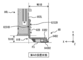
- FIG. 20A is a rear view showing details of the first support unit 8A in the first installation state (high position state), and FIG. 20B is a rear view showing the details of the first support unit 8A in the first installation state (high position state), and FIG. 20B is a first support unit in the second installation state (low position state). It is a rear view which shows the detail of 8A.
- FIG. 21 is an exploded perspective view of the base 81A. However, in FIG. 20A, the neck 80R is also shown, and in FIGS. 20B and 21, the neck 80L is also shown.
- FIG. 22A is a partially enlarged perspective view showing a positional relationship between a part of the first support unit 8A and the neck 80R in the first installation state, and FIG. 22B is a first view in the second installation state. It is a partially enlarged perspective view which shows the positional relationship between a part of a support unit 8A and a neck 80L.
- the base 81A includes a connecting portion 82A as a first connecting portion, leg portions 83A1, 83A2, and elastic members 84A1, 84A2.
- the base 81A can be attached to the neck 80R in the first posture and can be attached to the neck 80L in the second posture.
- the first posture referred to in the present embodiment is a posture in which the legs 83A1 and 83A2 are erected with respect to the mounting surface FS.
- the second posture referred to in the present embodiment is a posture in which the legs 83A1 and 83A2 are laid down so as to extend along the mounting surface FS.
- the connecting portion 82A of the base 81A can be connected to the neck 80R in the first posture and can be connected to the neck 80L in the second posture.
- the legs 83A and 83A2 are connected to the connecting portions 82A, respectively, and extend along the Z axis so as to be away from each other in the top view shown in FIGS. 17B and 18B, for example.
- the elastic member 84A1 is attached to the end of the leg 83A1 on the opposite side of the connecting portion 82A with an adhesive or the like
- the elastic member 84A2 is attached to the end of the leg 83A2 on the opposite side of the connecting portion 82A. It is attached to the door with an adhesive or the like.
- the first support unit 8A further includes, for example, a frame stand 85A as a first reinforcing member, a clamper 86A, and a cover 87A in addition to the base 81A.
- the frame stand 85A is attached so as to stand upright on the main surface of the leg 83A2 as the first plate-shaped member of the base 81A.
- the frame stand 85A is made of a high-rigidity material such as stainless steel, and is designed to prevent the legs 83A1 and 83A2 from being deformed by the load of the display unit 7 in the second installation state.
- the clamper 86A is a member that clamps a part of a power cable that supplies power to the main body 72 of the display unit 7, and a part of various signal cables that carry out signal transmission between the main body 72 and an external device, for example. ..
- the cover 87A is detachably provided so as to cover the frame stand 85A and the clamper 86A in order to enhance the appearance.
- the connecting portion 82A is provided with two screw holes 811A and 812A penetrating from the first surface 82S1A to the second surface 82S2A. Further, the first surface 82S1A of the connecting portion 82A is provided with two protrusions 813A and 814A (FIG. 22A), and the second surface 82S2A of the connecting portion 82A is provided with two protrusions 815A and 816A. (Fig. 22B).
- the neck 80R has a bottom plate portion 801R and a side plate portion 802R (FIG. 22A). The bottom plate portion 801R is provided with four holes 811R to 814R, respectively (FIG.
- the neck 80R and the base 81A are fastened by the two screws N8R1 and N8R2.
- the lower surface of the bottom plate portion 801R and the first surface 82S1A of the connecting portion 82A come into contact with each other, the screw N8R1 is screwed into the screw hole 811A via the hole 811R, and the screw N8R2 is screwed into the screw hole 812A via the hole 812R. It is designed to be screwed with.
- the base 81A can be easily positioned with respect to the neck 80R.
- the neck 80L has a bottom plate portion 801L and a side plate portion 802L.
- the side plate portion 802L is provided with four holes 821L, 822L, 825L, and 826L that penetrate through the side plate portion 802L, respectively.
- the neck 80L and the base 81A are fastened by the two screws N8L1 and N8L2.
- the outer surface of the side plate portion 802L and the second surface 82S2A of the connecting portion 82A come into contact with each other, the screw N8L1 is screwed into the screw hole 811A via the hole 821L, and the screw N8L2 is screwed into the screw hole 812A via the hole 822L.
- the base 81A can be easily positioned with respect to the neck 80L.
- the elastic members 84A1 and 84A2 are configured to be in contact with the mounting surface FS in both the first installation state (FIG. 20A) and the second installation state (FIG. 20B), respectively.
- the contact portion of the elastic members 84A1, 84A2 with respect to the mounting surface FS in the first installation state is different from the contact portion of the elastic members 84A1, 84A2 with respect to the mounting surface FS in the second installation state.
- the legs 83A1 and 83A2 are erected with respect to the mounting surface FS. Therefore, in the first installation state (FIG.
- the end surface 84TA1 of the elastic member 84A1 and the end surface 84TA2 of the elastic member 84A2 are in contact with the mounting surface FS, respectively.
- the legs 83A1, 83A2 are in a posture in which the main surfaces of the legs 83A1, 83A2 spread along the mounting surface FS. Therefore, in the second installation state (FIG. 20B), the main surface 84SA1 of the elastic member 84A1 and the main surface 84SA2 of the elastic member 84A2 are in contact with the mounting surface FS, respectively.
- the contact area between the mounting surface FS and the elastic members 84A1, 84A2 in the first installation state is based on the contact area between the mounting surface FS and the elastic members 84A1, 84A2 in the second installation state. Is also getting narrower.
- the ratio (W81A / T81A) of the dimension W81A in the Y-axis direction to the dimension T81A in the X-axis direction of the portion of the base 81A below the neck 80R in the first installation state is the second. It is larger than the ratio of the dimension T81A in the Y-axis direction to the dimension W81A in the X-axis direction (T81A / W81A) of the portion of the base 81A below the neck 80L in the installed state.
- FIG. 23A is a rear view showing details of the second support unit 8B in the first installation state (high position state), and FIG. 23B is a second support unit in the second installation state (low position state). It is a rear view which shows the detail of 8B.
- FIG. 24 is an exploded perspective view of the base 81B. However, in FIG. 23A, the neck 80L is also shown, and in FIGS. 23B and 24, the neck 80L is also shown.
- FIG. 25A is a partially enlarged perspective view showing a positional relationship between a part of the second support unit 8B and the neck 80L in the first installed state
- FIG. 25B is a second enlarged perspective view showing the positional relationship between the part of the second support unit 8B and the neck 80L. It is a partially enlarged perspective view which shows the positional relationship between a part of a support unit 8B and a neck 80R.
- the base 81B includes a connecting portion 82B as a second connecting portion, leg portions 83B1, 83B2, and elastic members 84B1, 84B2.
- the base 81B can be attached to the neck 80R in the third posture and can be attached to the neck 80L in the fourth posture.
- the third posture referred to in the present embodiment is a posture in which the legs 83B1 and 83B2 are laid down so as to extend along the mounting surface FS.
- the fourth posture referred to in the present embodiment is a posture in which the legs 83B1 and 83B2 are erected with respect to the mounting surface FS.
- the connecting portion 82B of the base 81B can be connected to the neck 80R in the third posture and can be connected to the neck 80L in the fourth posture.
- the legs 83B1 and 83B2 are connected to the connecting portions 82B, respectively, and extend along the Z axis so as to be away from each other in the top view shown in FIGS. 17B and 18B, for example.
- the elastic member 84B1 is attached to the end of the leg 83B1 on the opposite side of the connecting portion 82B with an adhesive or the like
- the elastic member 84B2 is attached to the end of the leg 83B2 on the opposite side of the connecting portion 82B. It is attached to the door with an adhesive or the like.
- the second support unit 8B further includes, for example, a frame stand 85B as a second reinforcing member, a clamper 86B, and a cover 87B in addition to the base 81B.
- the frame stand 85B is attached so as to stand upright on the main surface of the leg 83B2 as the second plate-shaped member of the base 81B.
- the frame stand 85B is made of a high-rigidity material such as stainless steel, and is designed to prevent the legs 83B1 and 83B2 from being deformed by the load of the display unit 7 in the second installation state.
- the clamper 86B is a member that clamps a part of a power cable that supplies power to the main body 72 of the display unit 7, and a part of various signal cables that carry out signal transmission between the main body 72 and an external device, for example. ..
- the cover 87B is detachably provided so as to cover the frame stand 85B and the clamper 86B in order to enhance the appearance.
- the connecting portion 82B is provided with two screw holes 811B and 812B penetrating from the first surface 82S1B to the second surface 82S2B. Further, the first surface 82S1B of the connecting portion 82B is provided with two protrusions 813B and 814B (FIG. 25A), and the second surface 82S2B of the connecting portion 82B is provided with two protrusions 815B and 816B. (Fig. 25B).
- the neck 80L has a bottom plate portion 801L and a side plate portion 802L (FIG. 25A).
- the bottom plate portion 801L is provided with four holes 811L to 814L, each of which penetrates (FIG. 25A).
- the neck 80L and the base 81B are fastened by the two screws N8L1 and N8L2.
- the lower surface of the bottom plate portion 801L and the first surface 82S1B of the connecting portion 82B are in contact with each other, the screw N8L1 is screwed into the screw hole 811B via the hole 811L, and the screw N8L2 is screwed into the screw hole 812B via the hole 812L. It is designed to be screwed with.
- the base 81L can be easily positioned with respect to the neck 80L.
- the neck 80R has a bottom plate portion 801R and a side plate portion 802R.
- the side plate portion 802R is provided with four holes 821R, 822R, 825R, and 826R, respectively, which penetrate through the side plate portion 802R.
- the neck 80R and the base 81B are fastened by the two screws N8R1 and N8R2.
- the outer surface of the side plate portion 802R and the second surface 82S2B of the connecting portion 82B are in contact with each other, the screw N8R1 is screwed into the screw hole 811B via the hole 821R, and the screw N8R2 is screwed into the screw hole 812B via the hole 822R.
- the base 81B can be easily positioned with respect to the neck 80R.
- the elastic members 84B1 and 84B2 are configured to be in contact with the mounting surface FS in both the first installation state (FIG. 23A) and the second installation state (FIG. 23B), respectively.
- the contact portion of the elastic members 84B1 and 84B2 with respect to the mounting surface FS in the first installation state and the contact portion of the elastic members 84B1 and 84B2 with respect to the mounting surface FS in the second installation state are different.
- the legs 83B1 and 83B2 are erected with respect to the mounting surface FS. Therefore, in the first installation state (FIG.
- the end surface 84TB1 of the elastic member 84B1 and the end surface 84TB2 of the elastic member 84B2 are in contact with the mounting surface FS, respectively.
- the legs 83B1 and 83B2 are in a posture in which the main surfaces of the legs 83B1 and 83B2 spread along the mounting surface FS. Therefore, in the second installation state (FIG. 23B), the main surface 84SB1 of the elastic member 84B1 and the main surface 84SB2 of the elastic member 84B2 are in contact with the mounting surface FS, respectively.
- the contact area between the mounting surface FS and the elastic members 84B1, 84B2 in the first installation state is based on the contact area between the mounting surface FS and the elastic members 84B1, 84B2 in the second installation state. Is also getting narrower.
- the ratio (W81B / T81B) of the dimension W81B in the Y-axis direction to the dimension T81B in the X-axis direction of the portion of the base 81B below the neck 80L in the first installation state is the second. It is larger than the ratio of the dimension T81B in the Y-axis direction to the dimension W81B in the X-axis direction (T81B / W81B) of the portion of the base 81B below the neck 80R in the installed state.
- the base 81A is mounted on the neck 80R in the first posture, and the base 81B is mounted on the neck 80L in the fourth posture. It has become. Further, in the second installation state, the base 81B is mounted on the neck 80R in the third posture, and the base 81A is mounted on the neck 80L in the second posture. That is, in the display device 400, the first support unit 8A and the second support unit 8B in the first installation state are rotated by approximately 90 °, respectively, and the left and right of the first support unit 8A and the second support unit 8B are rotated. It is possible to change to the second installation state by exchanging the installation position of.
- the first support unit 8A and the second support unit 8B in the second installation state are rotated by approximately 90 °, respectively, and the first support unit 8A and the second support unit 8A and the second support unit are rotated. It is possible to change to the first installation state by exchanging the left and right mounting positions of 8B.
- the display device 400 of the present embodiment by rearranging the first support unit 2A and the second support unit 2B with respect to the display unit 7, in addition to the above-described first installation state and second installation state, A third installation state and a fourth installation state can also be selected. That is, the display device 400 of the present embodiment can realize four viewing positions.
- FIG. 26A and 26B show an example of the overall configuration of the display device 400 in the third installation state.
- FIG. 26A is a front view of the display device 400 in the third installed state as viewed from the front (viewer side)
- FIG. 26B is a top view of the display device 400 in the third installed state as viewed from above. ..
- FIG. 27A and 27B show an example of the overall configuration of the display device 400 in the fourth installation state.
- FIG. 27A is a front view of the display device 400 in the fourth installed state as viewed from the front (viewer side)
- FIG. 27B is a top view of the display device 400 in the fourth installed state as viewed from above. ..
- the third height H3 (FIG. 26A) in the Y-axis direction from the mounting surface FS to the lower end of the display unit 7 is from the mounting surface FS in the fourth installation state to the display unit 7. It is higher than the fourth height H4 (FIG. 27A) in the Y-axis direction to the lower end. That is, the third installation state is the high position state in which the display unit 7 is installed at a relatively high position as in the first installation state, and the fourth installation state is the same as the second installation state. In addition, the display unit 7 is in a low position where it is installed at a relatively low position.
- the third height H3 is substantially the same as, for example, the first height H1 (FIG. 17A), and the fourth height H3 is substantially the same as, for example, the second height H2 (FIG. 18A). It is the same.
- the first support unit 8A is mounted in the mounting hole 73L (second position) of the display unit 7 via the neck 80L, and the second support unit 8B is mounted via the neck 80R.
- the display unit 7 is mounted in the mounting hole 73R (first position).
- the first support unit 8A is mounted in the mounting hole 73R (first position) of the display unit 7 via the neck 80R, and the second support unit 8B is mounted via the neck 80L. It is designed to be mounted in the mounting hole 73L (second position) of the display unit 7.
- FIG. 28A is a rear view showing the details of the neck 80L and the first support unit 8A in the third installation state
- FIG. 28B shows the details of the neck 80R and the second support unit 8B in the third installation state. It is a rear view showing.
- FIG. 29A is a rear view showing details of the neck 80L and the second support unit 8B in the fourth installation state
- FIG. 29B is a rear view of the neck 80R and the first support unit 8A in the fourth installation state. It is a rear view showing the details.
- the base 81A can be attached to the neck 80R in the fifth posture as shown in FIG. 29B, and can be attached to the neck 80L in the sixth posture as shown in FIG. 28A.
- the fifth posture referred to in the present embodiment is a posture in which the legs 83A1 and 83A2 are laid down so as to extend along the mounting surface FS.
- the connecting portion 82A of the base 81A is connected to the neck 80R, but is screwed so that the first surface 82S1A of the connecting portion 82A and the outer surface of the side plate portion 802R are in contact with each other. Will be done.
- the legs 83A1 and 83A2 are located on the opposite side of the neck 80R when viewed from the connecting portion 82A.
- the sixth posture referred to in the present embodiment is a posture in which the legs 83A1 and 83A2 are erected with respect to the mounting surface FS.
- the connecting portion 82A of the base 81A is connected to the neck 80L, but the legs 83A1 and 83A2 are connected to the inside of the neck 80L, that is, between the neck 80L and the center position CP. Connected to 82A.
- the base 81B can be attached to the neck 80R in the seventh posture as shown in FIG. 28B, and can be attached to the neck 80L in the eighth posture as shown in FIG. 29A.
- the seventh posture referred to in the present embodiment is a posture in which the legs 83B1 and 83B2 are erected with respect to the mounting surface FS.
- the connecting portion 82B of the base 81B is connected to the neck 80R, but the legs 83B1 and 83B2 are connected to the inside of the neck 80R, that is, between the neck 80R and the center position CP. Connected to 82B.
- the eighth posture referred to in the present embodiment is a posture in which the legs 83B1 and 83B2 are laid down so as to extend along the mounting surface FS.
- the connecting portion 82B of the base 81B is connected to the neck 80L, but is screwed so that the first surface 82S1B of the connecting portion 82B and the outer surface of the side plate portion 802L are in contact with each other. Will be done. Therefore, the legs 83B1 and 83B2 are located on the opposite side of the neck 80L when viewed from the connecting portion 82B.
- the display unit 7 is stably supported by the stand 8 as a support. Further, in the display device 400, the first installation state and the second installation state can be selected by rearranging the first support unit 8A and the second support unit 8B with respect to the display unit 7. Two viewing positions can be realized. Therefore, the support form of the display unit 7 can be selected according to the user's application, preference, installation environment, and the like.
- the high position state which is the first installation state
- the high position state it is possible to prevent the display surface 7A of the display unit 7 from being obstructed by other devices such as the sound bar SB.
- the low position state may be selected as shown in FIG. 18A. In that case, since the display unit 7 can be brought closer to the mounting surface FS, the aesthetics can be enhanced.
- the base 81A and the base 81B which are common in the first installation state and the second installation state, are used by exchanging the mounting positions, respectively.
- the elastic members 84A1, 84A2, 84B1, 84B2 are all provided so as to be in contact with the mounting surface FS in both the first installation state and the second installation state. For this reason, the number of parts is reduced as compared with the case where separate stands are used for the first installation state and the second installation state, which is advantageous for cost reduction, and the user does not need complicated work such as storage. And there is no risk of loss.
- the contact portion of the elastic member 84A1, 84A2, 84B1, 84B2 with respect to the mounting surface FS in the first installation state and the elastic member 84A1, 84A2, 84B1 with respect to the mounting surface FS in the second installation state. , 84B2 is different from the contact part, so the degree of freedom in design selection is improved.
- the contact area between the mounting surface FS in the first installation state and the elastic members 84A1, 84A2, 84B1, 84B2 in the bases 81A and 81B is the same as the mounting surface FS in the second installation state. It is smaller than the contact area with the elastic members 84A1, 84A2, 84B1, 84B2. Therefore, in the high position state, which is the first installation state, it is unlikely to interfere with the installation of other devices such as the sound bar.
- the dimensional ratios W81A / T81A and W81B / T81B in the first installation state are set to be larger than the dimensional ratios T81A / W81A and T81B / W81B in the second installation state, respectively. Therefore, the height difference between the first height H1 in the first installation state and the second height H2 in the second installation state can be further widened.
- the connecting portion 82A in the base 81A can be connected to the neck 80R by using the screws N8R1 and N8R2 in the first posture, and is connected to the neck 80L by using the screws N8L1 and N8L2 in the second posture. It is connectable, and the connecting portion 82B in the base 81B can be connected to the screw N8L1, N8L2 neck 80L in the fourth posture, and can be connected to the neck 80R using the screws N8R1 and N8R2 in the third posture. Therefore, the base 81A and the base 81B can be attached using the same screws N8L1, N8L2, N8L1, N8L2 in both the first installation state and the second installation state, respectively. Therefore, the number of parts is reduced, the configuration is simplified, and it is advantageous for cost reduction.
- the first support unit 8A and the second support unit 8B are provided with the frame stands 85A and 85B, respectively, they are based on the load of the display unit 7 especially in the second installation state. It is possible to prevent the 81A and 81B from being deformed. Therefore, the support stability of the display unit 7 by the stand 8 is further improved.
- the first contact member and the elastic member as the second contact member are placed on the mounting surface in both the first installation state and the second installation state. Contact is made, but the disclosure is not limited to this.
- the elastic member that contacts the mounting surface in the first installation state and the elastic member that contacts the mounting surface in the second installation state may be separated and provided only at necessary locations. ..
- the distance between the first support unit and the second support unit is changed or the height of the display unit is changed is exemplified in the first mode and the second mode.
- this disclosure is not limited to this.
- the elevation angle of the display surface of the display unit may be different between the first form and the second form.
- the display device described in the above embodiment is not limited to the case where all the components described above are provided, and some components may be omitted, or other components may be included. You may also have more.
- the first form and the second form can be selected by rearranging the first support unit and the second support unit. It is configured in. Therefore, it is possible to select the support form of the display unit according to the user's application and preference, installation environment, and the like.
- the present technology can have the following configurations. (1) It has a display surface that extends in the horizontal direction and the vertical direction, respectively, and has a center position in the horizontal direction and a first edge and a second edge that are located on opposite sides of the center position in the horizontal direction. A support that supports the display unit so that it stands upright on the mounting surface. A first support unit that is detachably provided to the display unit and It has a second support unit that is removable from the display unit and is provided as a separate body from the first support unit.
- the first support unit is attached to the first position between the center position and the first edge of the display unit in the horizontal direction, and the display unit is said to have the horizontal direction.
- the second form in which the first support unit is attached to the second position or the fourth position between the center position and the second edge in the horizontal direction is selectively configured. Support that is.
- the first support unit is a first mounting portion that is detachably formed on the display unit and a first that can come into contact with the above-mentioned mounting surface in both the first form and the second form. It has a first base that includes a contact member and The second support unit has a second mounting portion that is detachably formed on the display unit and a second mounting surface that can come into contact with the above-mentioned mounting surface in both the first form and the second form.
- the support according to (1) above which has a second base including a contact member.
- the first mounting portion and the first base portion are integrally formed.
- the support according to (2) or (3) above, wherein the second mounting portion and the second base portion are integrally formed.
- the distance between the first base and the center position in the first embodiment is longer than the distance between the first base and the center position in the second embodiment.
- the distance between the second base and the center position in the first form is longer than the distance between the second base and the center position in the second form (2) to (4).
- the ratio of the vertical dimension to the horizontal dimension of the first base in the first embodiment is the vertical dimension of the first base to the horizontal dimension in the second embodiment. Greater than the dimensional ratio of The ratio of the vertical dimension to the horizontal dimension of the second base in the first embodiment is the vertical dimension of the first base to the horizontal dimension in the second embodiment.
- the first mounting portion is attached to the first position so that at least a part of the first base portion protrudes to the side opposite to the center position when viewed from the first edge.
- the second mounting portion is attached to the second position so that at least a part of the second base portion protrudes to the side opposite to the center position when viewed from the second edge.
- the first mounting portion is attached to the fourth position and the second mounting portion is attached so that the first base portion fits between the first edge and the center position.
- the contact portion of the first contact member with respect to the previously described mounting surface in the first embodiment and the contact portion of the first contact member with respect to the previously described mounting surface in the second form are different.
- the support according to any one of (7).
- the contact area between the previously described mounting surface and the first contact member in the second embodiment is wider than the contact area between the previously described mounting surface and the first contact member in the first embodiment.
- the contact area between the previously described mounting surface and the second contact member in the second form is wider than the contact area between the previously described mounting surface and the first contact member in the first form (5).
- the first mounting portion and the second mounting portion are provided so as to be fixed to the display unit at a plurality of locations including three locations that are positions that are the vertices of a triangle, respectively (2).
- the first support unit further includes a first mounting portion and a first beam portion extending in the horizontal direction and connecting the first base portion.
- the support according to (2) above, wherein the second support unit further includes a second mounting portion and a second beam portion extending in the horizontal direction and connecting the second base portion.
- the contact portion of the first contact member with respect to the previously described mounting surface in the first embodiment and the contact portion of the first contact member with respect to the previously described mounting surface in the second form are the same.
- the contact portion of the second contact member with respect to the previously described mounting surface in the first embodiment and the contact portion of the second contact member with respect to the previously described mounting surface in the second form are the same (2).
- the display unit has a first hole provided at the first position and a second hole provided at the second position. In the first embodiment, the first mounting portion is inserted into the first hole to attach the first support unit to the display unit, and the second mounting portion is the second mounting portion. The second support unit is attached to the display unit by being inserted into the hole of 2.
- the second mounting portion is inserted into the first hole to attach the second support unit to the display unit, and the first mounting portion is the first.
- the first mounting portion is attached to the first position so that the first base portion fits between the first edge and the center position, and the second mounting portion is attached to the first position.
- the second mounting portion is attached to the second position so that the base is fitted between the second edge and the center position.
- the first mounting portion is attached to the second position so that the first base portion fits between the second edge and the center position, and the second mounting portion is attached to the second position.
- the first height in the vertical direction from the previously described mounting surface in the first embodiment to the lower end of the display unit is the vertical direction from the previously described mounting surface in the second form to the lower end of the display unit.
- the first mounting portion can be fixed to the first position by three or more first fasteners aligned on the first straight line in the first form, and the second mounting portion in the second form. It is provided so that it can be fixed to the second position by three or more second fasteners arranged in a straight line.
- the second mounting portion can be fixed to the second position by the three or more second fasteners arranged on the second straight line in the first form, and in the second form, the second mounting portion is described.
- the contact portion of the first contact member with respect to the previously described mounting surface in the first embodiment and the contact portion of the first contact member with respect to the previously described mounting surface in the second form are different from the above (15) or.
- (16) The support according to the above.
- the contact area between the previously described mounting surface and the first contact member in the first embodiment is narrower than the contact area between the previously described mounting surface and the first contact member in the second form.
- the contact area between the previously described mounting surface and the second contact member in the first embodiment is narrower than the contact area between the previously described mounting surface and the first contact member in the second form (15). )-(17).
- the support according to any one of (17). (19) A first mounting portion detachably formed at the first position of the display unit, It further has a second mounting portion that is detachably formed at the second position of the display unit.
- the first support unit has a first base that is connected to the first mounting portion in the first form and is connected to the second mounting portion in the second form.
- the second support unit has a second base that is connected to the second mounting portion in the first form and is connected to the first mounting portion in the second form (1).
- the first base includes a first contact member capable of contacting the above-mentioned mounting surface in both the first form and the second form.
- the first base portion can be mounted in a first posture with respect to the first mounting portion detachably provided at the first position of the display unit, and the second base portion of the display unit can be mounted.
- the second base can be mounted in a third posture with respect to the first mounting portion detachably provided at the first position of the display unit, and the second base of the display unit can be mounted.
- the second base is mounted on the first mounting portion in the third posture
- the first base is mounted on the second mounting portion in the third posture.
- the support according to (21) above which is mounted in the posture of 2.
- the first height in the vertical direction from the previously described mounting surface in the first embodiment to the lower end of the display unit is the vertical direction from the previously described mounting surface in the second form to the lower end of the display unit.
- the ratio of the vertical dimension to the horizontal dimension of the portion of the first base portion below the first mounting portion in the first embodiment is the ratio of the vertical dimension to the horizontal dimension in the second embodiment.
- the ratio of the vertical dimension to the horizontal dimension of the portion of the base 1 below the second mounting portion is the ratio of the vertical dimension to the horizontal dimension in the second embodiment.
- the first base includes a first connecting portion that is connectable to the first mounting portion in the first posture and is connectable to the second mounting portion in the second posture.
- the second base includes a second connecting portion that can be connected to the second mounting portion in the fourth posture and can be connected to the first mounting portion in the third posture.
- the contact portion of the first contact member with respect to the previously described mounting surface in the first embodiment is different from the contact portion of the first contact member with respect to the previously described mounting surface in the second form (20).
- Support. The contact area between the previously described mounting surface and the first contact member in the first embodiment is narrower than the contact area between the previously described mounting surface and the first contact member in the second form.
- the contact area between the previously described mounting surface and the second contact member in the first embodiment is narrower than the contact area between the previously described mounting surface and the first contact member in the second form (20).
- the first base portion includes a first plate-shaped member including a first surface intersecting the vertical direction in the second posture, and a first reinforcing member erected on the first surface.
- the second base has a second plate-shaped member including a second surface intersecting the vertical direction in the third posture, and a second reinforcing member erected on the second surface.
- the support according to any one of (19) to (27) above. (29) It has a display surface that extends in the horizontal direction and the vertical direction, respectively, and has a center position in the horizontal direction and a first edge and a second edge that are located on opposite sides of the center position in the horizontal direction.
- Display unit and A support that supports the display unit so as to stand on the mounting surface, and With The support A first support unit that is detachably provided to the display unit and It has a second support unit that is removable from the display unit and is provided as a separate body from the first support unit.
- the first support unit is attached to the first position between the center position and the first edge of the display unit in the horizontal direction, and the display unit is said to have the horizontal direction.
- the second form in which the first support unit is attached to the second position or the fourth position between the center position and the second edge in the horizontal direction is selectively configured. Display device.
Landscapes
- Physics & Mathematics (AREA)
- Engineering & Computer Science (AREA)
- Microelectronics & Electronic Packaging (AREA)
- Nonlinear Science (AREA)
- General Physics & Mathematics (AREA)
- Crystallography & Structural Chemistry (AREA)
- Mathematical Physics (AREA)
- Chemical & Material Sciences (AREA)
- Optics & Photonics (AREA)
- Signal Processing (AREA)
- Multimedia (AREA)
- Theoretical Computer Science (AREA)
- Devices For Indicating Variable Information By Combining Individual Elements (AREA)
Priority Applications (5)
| Application Number | Priority Date | Filing Date | Title |
|---|---|---|---|
| US17/757,905 US12075581B2 (en) | 2019-12-26 | 2020-12-17 | Supporting body and display apparatus |
| CN202080087009.4A CN114830635B (zh) | 2019-12-26 | 2020-12-17 | 支撑主体和显示设备 |
| JP2021567377A JP7684911B2 (ja) | 2019-12-26 | 2020-12-17 | 支持体および表示装置 |
| US18/772,388 US20250024616A1 (en) | 2019-12-26 | 2024-07-15 | Support body and display apparatus |
| JP2025082876A JP2025109880A (ja) | 2019-12-26 | 2025-05-16 | 支持体および表示装置 |
Applications Claiming Priority (4)
| Application Number | Priority Date | Filing Date | Title |
|---|---|---|---|
| JP2019-235743 | 2019-12-26 | ||
| JP2019235743 | 2019-12-26 | ||
| JP2020-169449 | 2020-10-06 | ||
| JP2020169449 | 2020-10-06 |
Related Child Applications (2)
| Application Number | Title | Priority Date | Filing Date |
|---|---|---|---|
| US17/757,905 A-371-Of-International US12075581B2 (en) | 2019-12-26 | 2020-12-17 | Supporting body and display apparatus |
| US18/772,388 Continuation US20250024616A1 (en) | 2019-12-26 | 2024-07-15 | Support body and display apparatus |
Publications (1)
| Publication Number | Publication Date |
|---|---|
| WO2021132041A1 true WO2021132041A1 (ja) | 2021-07-01 |
Family
ID=76574640
Family Applications (1)
| Application Number | Title | Priority Date | Filing Date |
|---|---|---|---|
| PCT/JP2020/047296 Ceased WO2021132041A1 (ja) | 2019-12-26 | 2020-12-17 | 支持体および表示装置 |
Country Status (4)
| Country | Link |
|---|---|
| US (2) | US12075581B2 (https=) |
| JP (2) | JP7684911B2 (https=) |
| CN (1) | CN114830635B (https=) |
| WO (1) | WO2021132041A1 (https=) |
Families Citing this family (1)
| Publication number | Priority date | Publication date | Assignee | Title |
|---|---|---|---|---|
| CN116324942A (zh) * | 2020-10-08 | 2023-06-23 | 索尼集团公司 | 支撑体和显示装置 |
Citations (3)
| Publication number | Priority date | Publication date | Assignee | Title |
|---|---|---|---|---|
| JP2013030499A (ja) * | 2011-07-26 | 2013-02-07 | Sony Corp | スタンド及び機器ユニット |
| WO2017098711A1 (ja) * | 2015-12-07 | 2017-06-15 | パナソニックIpマネジメント株式会社 | 映像表示装置 |
| JP2019120709A (ja) * | 2017-12-28 | 2019-07-22 | パナソニックIpマネジメント株式会社 | 画像表示装置 |
Family Cites Families (12)
| Publication number | Priority date | Publication date | Assignee | Title |
|---|---|---|---|---|
| US6676113B2 (en) * | 1997-04-22 | 2004-01-13 | Off The Wall Products, Llc | Control barrier with rotatable legs |
| JP3717876B2 (ja) | 2002-08-28 | 2005-11-16 | シャープ株式会社 | 液晶表示装置 |
| JP4396726B2 (ja) * | 2007-05-23 | 2010-01-13 | ソニー株式会社 | 表示装置 |
| JP2010015098A (ja) | 2008-07-07 | 2010-01-21 | Panasonic Corp | 映像表示装置 |
| WO2012057734A1 (en) * | 2010-10-25 | 2012-05-03 | Hewlett-Packard Development Company, L.P. | Touch-enabled video wall support system, apparatus, and method |
| JP2012120125A (ja) * | 2010-12-03 | 2012-06-21 | Sony Corp | 表示装置 |
| JP2012141385A (ja) | 2010-12-28 | 2012-07-26 | Jfe Steel Corp | 液晶表示装置のバックライトシャーシ |
| WO2015186603A1 (ja) * | 2014-06-06 | 2015-12-10 | シャープ株式会社 | 表示装置、及びテレビジョン受信機 |
| CN205750637U (zh) * | 2016-03-01 | 2016-11-30 | 鸿富锦精密电子(重庆)有限公司 | 电子设备 |
| KR102508214B1 (ko) * | 2018-08-30 | 2023-03-09 | 삼성전자주식회사 | 디스플레이 장치 |
| US20210267078A1 (en) * | 2020-02-26 | 2021-08-26 | ShenZhen Hongfei Precision Technology Co.,Ltd. | Electronic device and stand thereof |
| KR20220078900A (ko) * | 2020-12-04 | 2022-06-13 | 삼성전자주식회사 | 디스플레이 장치 |
-
2020
- 2020-12-17 CN CN202080087009.4A patent/CN114830635B/zh active Active
- 2020-12-17 WO PCT/JP2020/047296 patent/WO2021132041A1/ja not_active Ceased
- 2020-12-17 JP JP2021567377A patent/JP7684911B2/ja active Active
- 2020-12-17 US US17/757,905 patent/US12075581B2/en active Active
-
2024
- 2024-07-15 US US18/772,388 patent/US20250024616A1/en active Pending
-
2025
- 2025-05-16 JP JP2025082876A patent/JP2025109880A/ja active Pending
Patent Citations (3)
| Publication number | Priority date | Publication date | Assignee | Title |
|---|---|---|---|---|
| JP2013030499A (ja) * | 2011-07-26 | 2013-02-07 | Sony Corp | スタンド及び機器ユニット |
| WO2017098711A1 (ja) * | 2015-12-07 | 2017-06-15 | パナソニックIpマネジメント株式会社 | 映像表示装置 |
| JP2019120709A (ja) * | 2017-12-28 | 2019-07-22 | パナソニックIpマネジメント株式会社 | 画像表示装置 |
Also Published As
| Publication number | Publication date |
|---|---|
| US20250024616A1 (en) | 2025-01-16 |
| JP7684911B2 (ja) | 2025-05-28 |
| US12075581B2 (en) | 2024-08-27 |
| JPWO2021132041A1 (https=) | 2021-07-01 |
| CN114830635A (zh) | 2022-07-29 |
| JP2025109880A (ja) | 2025-07-25 |
| US20230030565A1 (en) | 2023-02-02 |
| CN114830635B (zh) | 2026-03-20 |
Similar Documents
| Publication | Publication Date | Title |
|---|---|---|
| JP2025109880A (ja) | 支持体および表示装置 | |
| KR20090104135A (ko) | 로봇 제어 디스플레이 | |
| KR20080102763A (ko) | 평판 디스플레이 및 이를 갖는 평판 디스플레이장치 | |
| JP2007132474A (ja) | 空間構造体 | |
| JP3182513B2 (ja) | パネル状家具 | |
| JP6473383B2 (ja) | ビューファインダ支持機構及びこれを備えたカメラ拡張装置 | |
| JP7805943B2 (ja) | 支持体および表示装置 | |
| JP2017112948A (ja) | 作業車両の操縦部 | |
| JP6937445B1 (ja) | モバイル用スタンド | |
| JP7312982B2 (ja) | ショーケース | |
| JP5542572B2 (ja) | プロジェクションユニットのキャビネット、プロジェクションユニット、及び、マルチビジョン装置 | |
| JP6920724B2 (ja) | Vr用メガネ | |
| JP2013010461A (ja) | カーナビゲーション装置及びそのディスプレイチルト調整部品 | |
| JP5079662B2 (ja) | 空間構造体 | |
| JP2012055466A (ja) | 商品陳列台 | |
| JP2019220912A (ja) | スタンド及び表示装置 | |
| JP6820620B1 (ja) | ゲーム機 | |
| JP5306893B2 (ja) | 測定装置 | |
| JP2004329402A (ja) | 陳列棚 | |
| JP4241313B2 (ja) | 棚装置 | |
| JP2019010381A (ja) | ショーケース | |
| JP2011232548A (ja) | 表示装置 | |
| WO2022059568A1 (ja) | 支持体および表示装置 | |
| JP3069785B2 (ja) | テーブル | |
| JP4899381B2 (ja) | 置き台およびテレビジョン受像機 |
Legal Events
| Date | Code | Title | Description |
|---|---|---|---|
| 121 | Ep: the epo has been informed by wipo that ep was designated in this application |
Ref document number: 20906845 Country of ref document: EP Kind code of ref document: A1 |
|
| ENP | Entry into the national phase |
Ref document number: 2021567377 Country of ref document: JP Kind code of ref document: A |
|
| NENP | Non-entry into the national phase |
Ref country code: DE |
|
| 122 | Ep: pct application non-entry in european phase |
Ref document number: 20906845 Country of ref document: EP Kind code of ref document: A1 |