WO2021124390A1 - 熱交換器、熱交換器ユニット、及び冷凍サイクル装置 - Google Patents
熱交換器、熱交換器ユニット、及び冷凍サイクル装置 Download PDFInfo
- Publication number
- WO2021124390A1 WO2021124390A1 PCT/JP2019/049152 JP2019049152W WO2021124390A1 WO 2021124390 A1 WO2021124390 A1 WO 2021124390A1 JP 2019049152 W JP2019049152 W JP 2019049152W WO 2021124390 A1 WO2021124390 A1 WO 2021124390A1
- Authority
- WO
- WIPO (PCT)
- Prior art keywords
- header
- heat exchange
- exchange member
- heat exchanger
- heat
- Prior art date
- Legal status (The legal status is an assumption and is not a legal conclusion. Google has not performed a legal analysis and makes no representation as to the accuracy of the status listed.)
- Ceased
Links
Images







Classifications
-
- F—MECHANICAL ENGINEERING; LIGHTING; HEATING; WEAPONS; BLASTING
- F28—HEAT EXCHANGE IN GENERAL
- F28D—HEAT-EXCHANGE APPARATUS, NOT PROVIDED FOR IN ANOTHER SUBCLASS, IN WHICH THE HEAT-EXCHANGE MEDIA DO NOT COME INTO DIRECT CONTACT
- F28D1/00—Heat-exchange apparatus having stationary conduit assemblies for one heat-exchange medium only, the media being in contact with different sides of the conduit wall, in which the other heat-exchange medium is a large body of fluid, e.g. domestic or motor car radiators
- F28D1/02—Heat-exchange apparatus having stationary conduit assemblies for one heat-exchange medium only, the media being in contact with different sides of the conduit wall, in which the other heat-exchange medium is a large body of fluid, e.g. domestic or motor car radiators with heat-exchange conduits immersed in the body of fluid
- F28D1/04—Heat-exchange apparatus having stationary conduit assemblies for one heat-exchange medium only, the media being in contact with different sides of the conduit wall, in which the other heat-exchange medium is a large body of fluid, e.g. domestic or motor car radiators with heat-exchange conduits immersed in the body of fluid with tubular conduits
- F28D1/053—Heat-exchange apparatus having stationary conduit assemblies for one heat-exchange medium only, the media being in contact with different sides of the conduit wall, in which the other heat-exchange medium is a large body of fluid, e.g. domestic or motor car radiators with heat-exchange conduits immersed in the body of fluid with tubular conduits the conduits being straight
- F28D1/0535—Heat-exchange apparatus having stationary conduit assemblies for one heat-exchange medium only, the media being in contact with different sides of the conduit wall, in which the other heat-exchange medium is a large body of fluid, e.g. domestic or motor car radiators with heat-exchange conduits immersed in the body of fluid with tubular conduits the conduits being straight the conduits having a non-circular cross-section
- F28D1/05366—Assemblies of conduits connected to common headers, e.g. core type radiators
- F28D1/05383—Assemblies of conduits connected to common headers, e.g. core type radiators with multiple rows of conduits or with multi-channel conduits
-
- F—MECHANICAL ENGINEERING; LIGHTING; HEATING; WEAPONS; BLASTING
- F28—HEAT EXCHANGE IN GENERAL
- F28D—HEAT-EXCHANGE APPARATUS, NOT PROVIDED FOR IN ANOTHER SUBCLASS, IN WHICH THE HEAT-EXCHANGE MEDIA DO NOT COME INTO DIRECT CONTACT
- F28D1/00—Heat-exchange apparatus having stationary conduit assemblies for one heat-exchange medium only, the media being in contact with different sides of the conduit wall, in which the other heat-exchange medium is a large body of fluid, e.g. domestic or motor car radiators
- F28D1/02—Heat-exchange apparatus having stationary conduit assemblies for one heat-exchange medium only, the media being in contact with different sides of the conduit wall, in which the other heat-exchange medium is a large body of fluid, e.g. domestic or motor car radiators with heat-exchange conduits immersed in the body of fluid
- F28D1/04—Heat-exchange apparatus having stationary conduit assemblies for one heat-exchange medium only, the media being in contact with different sides of the conduit wall, in which the other heat-exchange medium is a large body of fluid, e.g. domestic or motor car radiators with heat-exchange conduits immersed in the body of fluid with tubular conduits
- F28D1/053—Heat-exchange apparatus having stationary conduit assemblies for one heat-exchange medium only, the media being in contact with different sides of the conduit wall, in which the other heat-exchange medium is a large body of fluid, e.g. domestic or motor car radiators with heat-exchange conduits immersed in the body of fluid with tubular conduits the conduits being straight
-
- F—MECHANICAL ENGINEERING; LIGHTING; HEATING; WEAPONS; BLASTING
- F28—HEAT EXCHANGE IN GENERAL
- F28F—DETAILS OF HEAT-EXCHANGE AND HEAT-TRANSFER APPARATUS, OF GENERAL APPLICATION
- F28F1/00—Tubular elements; Assemblies of tubular elements
- F28F1/02—Tubular elements of cross-section which is non-circular
- F28F1/025—Tubular elements of cross-section which is non-circular with variable shape, e.g. with modified tube ends, with different geometrical features
-
- F—MECHANICAL ENGINEERING; LIGHTING; HEATING; WEAPONS; BLASTING
- F28—HEAT EXCHANGE IN GENERAL
- F28F—DETAILS OF HEAT-EXCHANGE AND HEAT-TRANSFER APPARATUS, OF GENERAL APPLICATION
- F28F1/00—Tubular elements; Assemblies of tubular elements
- F28F1/10—Tubular elements and assemblies thereof with means for increasing heat-transfer area, e.g. with fins, with projections, with recesses
- F28F1/12—Tubular elements and assemblies thereof with means for increasing heat-transfer area, e.g. with fins, with projections, with recesses the means being only outside the tubular element
- F28F1/14—Tubular elements and assemblies thereof with means for increasing heat-transfer area, e.g. with fins, with projections, with recesses the means being only outside the tubular element and extending longitudinally
- F28F1/16—Tubular elements and assemblies thereof with means for increasing heat-transfer area, e.g. with fins, with projections, with recesses the means being only outside the tubular element and extending longitudinally the means being integral with the element, e.g. formed by extrusion
-
- F—MECHANICAL ENGINEERING; LIGHTING; HEATING; WEAPONS; BLASTING
- F28—HEAT EXCHANGE IN GENERAL
- F28F—DETAILS OF HEAT-EXCHANGE AND HEAT-TRANSFER APPARATUS, OF GENERAL APPLICATION
- F28F9/00—Casings; Header boxes; Auxiliary supports for elements; Auxiliary members within casings
- F28F9/02—Header boxes; End plates
- F28F9/0246—Arrangements for connecting header boxes with flow lines
-
- F—MECHANICAL ENGINEERING; LIGHTING; HEATING; WEAPONS; BLASTING
- F28—HEAT EXCHANGE IN GENERAL
- F28F—DETAILS OF HEAT-EXCHANGE AND HEAT-TRANSFER APPARATUS, OF GENERAL APPLICATION
- F28F1/00—Tubular elements; Assemblies of tubular elements
- F28F1/02—Tubular elements of cross-section which is non-circular
- F28F1/022—Tubular elements of cross-section which is non-circular with multiple channels
-
- F—MECHANICAL ENGINEERING; LIGHTING; HEATING; WEAPONS; BLASTING
- F28—HEAT EXCHANGE IN GENERAL
- F28F—DETAILS OF HEAT-EXCHANGE AND HEAT-TRANSFER APPARATUS, OF GENERAL APPLICATION
- F28F1/00—Tubular elements; Assemblies of tubular elements
- F28F1/10—Tubular elements and assemblies thereof with means for increasing heat-transfer area, e.g. with fins, with projections, with recesses
- F28F1/12—Tubular elements and assemblies thereof with means for increasing heat-transfer area, e.g. with fins, with projections, with recesses the means being only outside the tubular element
- F28F1/14—Tubular elements and assemblies thereof with means for increasing heat-transfer area, e.g. with fins, with projections, with recesses the means being only outside the tubular element and extending longitudinally
- F28F1/16—Tubular elements and assemblies thereof with means for increasing heat-transfer area, e.g. with fins, with projections, with recesses the means being only outside the tubular element and extending longitudinally the means being integral with the element, e.g. formed by extrusion
- F28F1/18—Tubular elements and assemblies thereof with means for increasing heat-transfer area, e.g. with fins, with projections, with recesses the means being only outside the tubular element and extending longitudinally the means being integral with the element, e.g. formed by extrusion the element being built-up from finned sections
-
- F—MECHANICAL ENGINEERING; LIGHTING; HEATING; WEAPONS; BLASTING
- F28—HEAT EXCHANGE IN GENERAL
- F28F—DETAILS OF HEAT-EXCHANGE AND HEAT-TRANSFER APPARATUS, OF GENERAL APPLICATION
- F28F2275/00—Fastening; Joining
- F28F2275/04—Fastening; Joining by brazing
- F28F2275/045—Fastening; Joining by brazing with particular processing steps, e.g. by allowing displacement of parts during brazing or by using a reservoir for storing brazing material
Definitions
- the present invention relates to a heat exchanger, a heat exchanger unit provided with the heat exchanger, and a refrigeration cycle device, and particularly to a structure of a portion inserted into a header of a heat exchange member.
- a heat exchanger having a heat exchange member provided with fins and a heat transfer tube so as to extend the fins along the tube axis direction of the heat transfer tube is known.
- the end of the heat exchange member is inserted into the header, and the entire end face of the fin is in contact with the header, or the entire end face of the fin is arranged apart from the header.
- the heat exchange member of Patent Document 1 has a long length in which the fin and the header are in contact or joined.
- the brazing material flows into the gap between the fin and the header due to the capillary force. Therefore, when the length of contact or bonding between the fin and the header is long, it is necessary to increase the amount of brazing material supplied between the fin and the header. As a result, the heat exchanger has a problem that the heat exchange member is damaged due to erosion or the like.
- the present invention is for solving the above-mentioned problems, and provides a heat exchanger, a heat exchanger unit, and a refrigeration cycle device capable of suppressing damage to a heat transfer tube due to a joint between a heat exchange member and a header.
- the purpose is.
- the heat exchanger includes a heat exchange member extending in the first direction and a header to which the heat exchange member is connected, and the heat exchange member is at least one transfer extending in the first direction.
- a heat tube and fins formed on a part of the edge of the at least one heat transfer tube in the second direction intersecting the first direction are provided, and the end portion of the heat exchange member in the first direction is provided. It includes an insertion portion to be inserted inside the header, a contact portion that comes into contact with the header at a portion other than the insertion portion, and a separation portion that is separated from the header at a portion other than the insertion portion.
- the heat exchanger unit according to the present invention includes the above heat exchanger.
- the refrigeration cycle device includes the above heat exchanger unit.
- the fins of the heat exchange member and the header are joined with an appropriate joining length.
- the heat exchanger suppresses the amount of brazing material used when joining the heat exchange member and the header, and can perform proper joining, so that damage to the heat exchange member can be suppressed.
- FIG. 3 is a three-view view of the heat exchange member 10 according to the first embodiment.
- FIG. 3 is a three-view view of the first header 30 of the heat exchanger 100 according to the first embodiment.
- FIG. 5 is an enlarged view of a connection portion between the heat exchange member 10 of the heat exchanger 100 and the first header 30 according to the first embodiment.
- It is a top view which shows the modification of the structure of the fin 12 of the heat exchange member 10 which concerns on Embodiment 1.
- FIG. 10A shows the modification of the structure of the fin 12 of the heat exchange member 10 which concerns on Embodiment 1.
- FIG. It is a three-view view of the heat exchange member 10A which is a modification of the heat exchange member 10 which concerns on Embodiment 1.
- FIG. It is an enlarged view of the connection part between the heat exchange member 10A of FIG. 8 and the first header 30.
- It is a three-view view of the heat exchange member 10B which is a modification of the heat exchange member 10 which concerns on Embodiment 1.
- FIG. FIG. 5 is an enlarged view of a connection portion between the heat exchange member 10B and the first header 30 in FIG.
- FIG. 3 is a three-view view of the heat exchange member 210A according to the second embodiment.
- FIG. 5 is an enlarged view of a connection portion between the heat exchange member 210A of the heat exchanger 200 and the first header 30 according to the second embodiment.
- FIG. 3 is a three-view view of the heat exchange member 210B according to the second embodiment.
- FIG. 5 is an enlarged view of a connection portion between the heat exchange member 210B of the heat exchanger 200 and the first header 30 according to the second embodiment.
- 3 is a three-view view of the header 302 of the heat exchanger 300 according to the third embodiment.
- FIG. 5 is an enlarged view of a connection portion between the heat exchange member 310 and the first header 330 of the heat exchanger 300 according to the third embodiment.
- FIG. 5 is an enlarged view of a connection portion between the heat exchange member 310 of the heat exchanger 300 according to the third embodiment and the first header 330B which is a modification of the first header 330.
- FIG. 5 is an enlarged view of a connection portion between the heat exchange member 310 of the heat exchanger 300 according to the third embodiment and the first header 330C which is a modification of the first header 330.
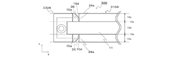
- FIG. 5 is an enlarged view of a connection portion between a heat exchange member 310A which is a modification of the heat exchange member 310 of the heat exchanger 300 according to the third embodiment and a first header 330A which is a modification of the first header 330.
- FIG. 5 is an enlarged view of a connection portion between a heat exchange member 310A which is a modification of the heat exchange member 310 of the heat exchanger 300 according to the third embodiment and a first header 330B which is a modification of the first header 330.
- FIG. 5 is an enlarged view of a connection portion between a heat exchange member 310A which is a modification of the heat exchange member 310 of the heat exchanger 300 according to the third embodiment and a first header 330C which is a modification of the first header 330.
- FIG. 5 is an enlarged view of a connection portion between a heat exchange member 310B which is a modification of the heat exchange member 310 of the heat exchanger 300 according to the third embodiment and a first header 330A which is a modification of the first header 330.
- FIG. 3 is a three-view view of the heat exchange member 410 according to the fourth embodiment. It is a three-view view of the heat exchange member 510 of the heat exchange member 510 according to the fifth embodiment.
- FIG. 1 is a refrigerant circuit diagram showing a configuration of a refrigeration cycle device 50 including the heat exchanger 100 according to the first embodiment.
- the arrow indicated by the dotted line indicates the direction in which the refrigerant flows in the refrigerant circuit 110 during the cooling operation
- the arrow indicated by the solid line indicates the direction in which the refrigerant flows during the heating operation. ..
- the refrigeration cycle apparatus 50 provided with the heat exchanger 100 will be described with reference to FIG.
- the air conditioner is illustrated as the refrigerating cycle device 50, but the refrigerating cycle device 50 is used for refrigerating applications such as refrigerators or freezers, vending machines, air conditioners, refrigerating devices, and water heaters. Or used for air conditioning.
- the illustrated refrigerant circuit 110 is an example, and the configuration of circuit elements and the like is not limited to the contents described in the embodiment, and can be appropriately changed within the scope of the technique according to the embodiment. ..
- the refrigeration cycle device 50 has a refrigerant circuit 110 in which a compressor 101, a flow path switching device 102, an indoor heat exchanger 103, a decompression device 104, and an outdoor heat exchanger 105 are connected in a ring shape via a refrigerant pipe. ..
- a heat exchanger 100 which will be described later, is used for at least one of the outdoor heat exchanger 105 and the indoor heat exchanger 103.
- the refrigeration cycle device 50 has an outdoor unit 106 and an indoor unit 107.
- a device having a heat exchanger inside, such as the outdoor unit 106 and the indoor unit 107, may be referred to as a heat exchanger unit.
- the outdoor unit 106 includes a compressor 101, a flow path switching device 102, an outdoor heat exchanger 105 and a decompression device 104, and an outdoor blower 108 that supplies outdoor air to the outdoor heat exchanger 105.
- the indoor unit 107 includes an indoor heat exchanger 103 and an indoor blower 109 that supplies air to the indoor heat exchanger 103.
- the outdoor unit 106 and the indoor unit 107 are connected via two extension pipes 111 and 112 which are a part of the refrigerant pipe.
- the compressor 101 is a fluid machine that compresses and discharges the sucked refrigerant.
- the flow path switching device 102 is, for example, a four-way valve, and is a device that switches the flow path of the refrigerant between the cooling operation and the heating operation by controlling the control device (not shown).
- the indoor heat exchanger 103 is a heat exchanger that exchanges heat between the refrigerant circulating inside and the indoor air supplied by the indoor blower 109.
- the indoor heat exchanger 103 functions as a condenser during the heating operation and as an evaporator during the cooling operation.
- the pressure reducing device 104 is, for example, an expansion valve, which is a device for reducing the pressure of the refrigerant.
- an electronic expansion valve whose opening degree is adjusted by the control of the control device can be used.
- the outdoor heat exchanger 105 is a heat exchanger that exchanges heat between the refrigerant circulating inside and the air supplied by the outdoor blower 108.
- the outdoor heat exchanger 105 functions as an evaporator during the heating operation and as a condenser during the cooling operation.
- the low-pressure gas-liquid two-phase refrigerant flows into the outdoor heat exchanger 105 and evaporates by heat exchange with the air supplied by the outdoor blower 108.
- the evaporated refrigerant becomes a low-pressure gas state and is sucked into the compressor 101.
- the refrigerant flowing through the refrigerant circuit 110 flows in the opposite direction to that during the heating operation. That is, during the cooling operation of the refrigeration cycle device 50, the high-pressure and high-temperature gas-state refrigerant discharged from the compressor 101 flows into the outdoor heat exchanger 105 via the flow path switching device 102 and is supplied by the outdoor blower 108. It exchanges heat with the air and condenses.
- the condensed refrigerant is in a high-pressure liquid state, flows out of the outdoor heat exchanger 105, and is in a low-pressure gas-liquid two-phase state by the decompression device 104.
- the low-pressure gas-liquid two-phase refrigerant flows into the indoor heat exchanger 103 and evaporates by heat exchange with the air supplied by the indoor blower 109.
- the evaporated refrigerant becomes a low-pressure gas state and is sucked into the compressor 101.
- FIG. 2 is a three-view view showing a configuration of a main part of the heat exchanger 100 according to the first embodiment.
- 2A is a front view of the heat exchanger 100
- FIG. 2B is a side view of the heat exchanger 100
- FIG. 2C is a bottom view of the heat exchanger 100.
- the arrow RF indicates the flow of the refrigerant flowing into or out of the heat exchanger 100.
- the heat exchanger 100 includes a plurality of heat exchange members 10 and a first header 30 and a second header 40 connected to both ends of the plurality of heat exchange members 10 in the y direction.
- a plurality of heat exchange members 10 are arranged in the x direction. Further, the plurality of heat exchange members 10 are extended in the y direction, and the pipe axes are arranged along the y direction.
- the y direction is parallel to the gravity direction. However, the arrangement of the heat exchanger 100 is not limited to this, and the y direction may be inclined with respect to the gravity direction. Further, the intervals of the plurality of heat exchange members 10 are equal to each other, and are arranged at predetermined intervals in the x direction.
- the tube axis direction of the plurality of heat exchange members 10, that is, the y direction is the first direction
- the width direction of the plurality of heat exchange members 10, that is, the z direction is the second direction
- the plurality of heat exchange members 10 are arranged.
- the direction, that is, the x direction may be referred to as a third direction.
- One end 13a of the plurality of heat exchange members 10 in the pipe axial direction is connected to the first header 30. Further, the other end 13b of the plurality of heat exchange members 10 in the pipe axial direction is connected to the second header 40.
- the first header 30 and the second header 40 are arranged so that the plurality of heat exchange members 10 are oriented in the longitudinal direction in the parallel direction.
- the longitudinal directions of the first header 30 and the second header 40 are parallel to each other.
- the first header 30 and the second header 40 may be collectively referred to as the header 2.
- a part of the ends 13a and 13b of the plurality of heat exchange members 10 is inserted into the header 2 and joined by brazing or a joining means such as an adhesive.
- a portion of the heat exchange member 10 other than the portion inserted in the header 2 is referred to as a heat exchange portion 10f.
- the plurality of heat exchange members 10 position the heat exchange portion 10f between the lower surface of the first header 30 and the upper surface of the second header 40.
- the heat exchanger 100 is a so-called finless heat exchanger that does not have a corrugated fin or the like that connects the side surfaces 11a of the heat transfer tube 11 of the heat exchange member 10 between each of the plurality of heat exchange members 10. That is, the plurality of heat exchange members 10 are connected to each other only by the header 2, and a space is formed between the side surfaces of the plurality of adjacent heat exchange members 10. The distance between the side surfaces of the plurality of heat exchange members 10 is set to be narrow in order to improve the heat exchange efficiency.
- FIG. 3 is a three-view view of the heat exchange member 10 according to the first embodiment.
- 3A is a front view of the heat exchange member 10
- FIG. 3B is a side view of the heat exchange member 10
- FIG. 3C is a top view of the heat exchange member 10.
- each of the plurality of heat exchange members 10 includes a heat transfer tube 11 which is a flat tube extending in the y direction, and fins 12 so as to extend in the z direction from a part of the end edge 14 of the heat transfer tube 11. ..
- the heat transfer tube 11 is formed with a refrigerant flow path 18, and allows the refrigerant to flow inside.
- Each of the plurality of heat exchange members 10 extends between the first header 30 and the second header 40.
- the plurality of heat exchange members 10 are arranged so as to face each other on the side surfaces 11a.
- a gap which is an air flow path, is formed between two adjacent heat exchange members 10 among the plurality of heat exchange members 10.
- the parallel direction of the plurality of heat exchange members 10 is the horizontal direction.
- the parallel direction of the plurality of heat exchange members 10 is not limited to the horizontal direction, and may be a vertical direction or a direction inclined with respect to the vertical direction.
- the pipe axis direction of the plurality of heat exchange members 10 is the vertical direction.
- the stretching direction of the plurality of heat exchange members 10 is not limited to the vertical direction, and may be a horizontal direction or a direction inclined with respect to the vertical direction.
- the heat exchanger 100 When the heat exchanger 100 functions as an evaporator of the refrigeration cycle device 50, in each of the plurality of heat exchange members 10, the refrigerant inside the heat exchange member 10 from one end face 19a in the y direction toward the other end face 19b. Flows. Further, when the heat exchanger 100 functions as a condenser of the refrigeration cycle device 50, in each of the plurality of heat exchange members 10, the inside of the heat exchange member 10 is directed from the other end surface 19b in the y direction to one end surface 19a. Refrigerant flows.
- the heat exchange member 10 includes a heat transfer tube 11 and fins 12.
- the heat transfer tube 11 of the heat exchange member 10 is a flat multi-hole tube having a flat cross-sectional shape in one direction such as an oval shape.
- fins 12 extend from a part of the end edge 14 in the long axis direction of the heat transfer tube 11 in a cross section perpendicular to the y direction.
- the heat exchange member 10 has a portion where the fin 12 is not installed at the end edge 14 of the heat transfer tube 11. The portion of the heat exchange member 10 where the fin 12 is not installed at the end edge 14 of the heat transfer tube 11 is inserted inside the first header 30 and the second header 40.
- the heat exchange member 10 communicates the first header 30 and the second header 40 by inserting a part of each of the end portions 13a and 13b into the first header 30 and the second header 40.
- the ends 13a and 13b of the heat exchange member 10 are composed of a plurality of parts defined by being separated in the z direction.
- the plurality of portions are a non-insertion portion 10a and an insertion portion 10b defined by being separated by a virtual line along the pipe axis of the heat exchange member 10. Further, the boundary between the non-insertion portion 10a and the insertion portion 10b is referred to as a switching portion 10c.
- the portion of the heat transfer tube 11 corresponds to the insertion portion 10b
- the portion of the fin 12 corresponds to the non-insertion portion 10a.
- the insertion portion 10b is a portion of the end portion of the heat exchange member 10 in the y direction to be inserted into the header 2.
- the non-insertion portion 10a refers to a portion of the end portion of the heat exchange member 10 in the y direction other than the insertion portion 10b.
- the fin 12 which is the non-insertion portion 10a includes a separation portion 10d and a contact portion 10e on the end surface in the y direction.
- the contact portion 10e comes into contact with the header 2 at a portion other than the insertion portion 10b.
- the separating portion 10d is separated from the header 2 in a portion other than the insertion portion 10b.
- the separating portion 10d and the contact portion 10e form an end surface of the fin 12 in the y direction, but the contact portion 10e is located closer to the end faces 19a and 19b of the heat exchange member 10 than the separating portion 10d.
- the contact portion 10e is located closer to the header 2 than the separation portion 10d, and is located between the insertion portion 10b and the separation portion 10d in the z direction.
- FIG. 4 is a three-view view of the first header 30 of the heat exchanger 100 according to the first embodiment.
- 4A is a front view of the first header 30
- FIG. 4B is a side view of the first header 30
- FIG. 4C is a top view of the first header 30. ..
- Each of the first header 30 and the second header 40 extends in the x direction, is configured so that the refrigerant flows inside, and the heat exchange member 10 is connected to the first header 30 and the second header 40.
- the refrigerant flows in from one end of the first header 30 in the direction of arrow RF, and the refrigerant is distributed to each of the plurality of heat exchange members 10.
- the refrigerants that have passed through the plurality of heat exchange members 10 merge at the second header 40 and flow out from one end of the second header 40.
- the outer shape of the header 2 is a rectangular parallelepiped, but the shape is not limited.
- the outer shape of the header 2 may be, for example, a cylinder or an elliptical pillar, and the cross-sectional shape can be changed as appropriate.
- a tubular body with both ends closed, a plate-shaped body having slits formed therein, and the like can be adopted as the structure of the header 2, for example, a tubular body with both ends closed, a plate-shaped body having slits formed therein, and the like can be adopted.
- the first header 30 is formed with a refrigerant flow port 33 through which the refrigerant can flow in and out
- the second header 40 is formed with a refrigerant flow port 43 through which the refrigerant can flow in and out.
- the first header 30 is formed in a rectangular parallelepiped shape by combining the first outer member 31 forming the upper surface 34a of the header and the second outer member 32 forming the bottom.
- a refrigerant flow port 33 is provided at the end of the second outer member 32 in the x-reverse direction.
- a plurality of insertion holes 31a are formed in the header upper surface 34a of the first header 30.
- the plurality of insertion holes 31a correspond to the plurality of heat exchange members 10 and are arranged in parallel in the x direction.
- the plurality of insertion holes 31a are holes into which the respective insertion portions 10b of the plurality of heat exchange members 10 are inserted, and penetrate the first outer member 31 in the surface direction.
- the second header 40 has the same structure as the first header 30.
- FIG. 5 is an enlarged view of a connection portion between the heat exchange member 10 and the first header 30 of the heat exchanger 100 according to the first embodiment.
- the heat transfer tube 11 which is the insertion portion 10b of the end portions 13a and 13b of the heat exchange member 10 is inserted into the insertion hole 31a of the first header 30.
- the insertion hole 31a has a shape that follows the shape of the outer peripheral surface of the insertion portion 10b.
- the insertion portion 10b and the insertion hole 31a are joined by, for example, brazing so that the refrigerant flowing inside the heat exchanger 100 does not flow out.
- the contact portion 10e of the fin 12 which is the non-insertion portion 10a is in contact with the header upper surface 34a of the first header 30, and the separation portion 10d of the fin 12 which is the non-insertion portion 10a is the first header 30. It is located away from the top surface 34a of the header. It is sufficient that at least a part of the surface of the contact portion 10e facing the header upper surface 34a of the first header 30 is in contact with the header upper surface 34a of the first header 30. Further, the separating portion 10d may be formed on a part of the surface of the first header 30 facing the header upper surface 34a in the y direction. In FIG.
- the tip of the fin 12 is aligned with the end surface 35 of the header 2, but the fin 12 has a structure such that the tip of the fin 12 protrudes from the end surface 35 of the header 2.
- the separation portion 10d is formed at a position facing the first header 30 in the y direction.
- the heat exchanger 100 uniquely determines the positional relationship between the heat exchange member 10 and the header 2, and facilitates the positioning of the heat exchange member 10 with respect to the header 2.
- the position can be easily determined only by combining the heat exchange member 10 and the header 2 without particularly providing a process for positioning the heat exchange member 10 and the header 2 and a jig. , Easy to manufacture. Therefore, the length of contact between the heat exchange member 10 and the header 2, that is, the length of contact between the fins 12 of the heat exchange member 10 and the header upper surface 34a of the header 2 becomes shorter, so that the heat exchange member 10 and the header 2 become The amount of brazing material can be reduced when brazing and joining.
- the heat exchanger 100 can suppress the manufacturing cost while ensuring the sealing property and strength of the joint portion between the heat exchange member 10 and the header 2. Further, the heat exchanger 100 can suppress damage to the heat transfer tube due to erosion by reducing the amount of brazing material that joins the heat exchange member 10 and the header 2.
- the non-insertion portion 10a is composed of a part of the fins 12.
- the contact portion 10e is an end surface of the fin 12 in the y direction, and is located on the header 2 side of the separation portion 10d.
- FIG. 6 and 7 are top views showing a modified example of the structure of the fin 12 of the heat exchange member 10 according to the first embodiment.
- FIG. 6 is a diagram corresponding to FIG. 3 (c).
- the fins 12 of the heat exchange member 10 are not limited to those integrally molded with the heat transfer tube 11, and have, for example, a structure in which fins 12 formed by bending a plate-shaped member into a flat multi-hole tube are joined later. You may.
- the heat exchange member 10 shown in FIG. 6 is configured by sandwiching a heat transfer tube 11 which is a flat multi-hole tube with plate-shaped members from side surfaces 11a on both sides of the heat transfer tube 11.
- the plate-shaped members are arranged along the outer peripheral surface of the heat transfer tube 11. Then, in the plate-shaped member, the portions protruding from the heat transfer tube 11 in the z direction are joined to form the fin 12.
- the heat exchange member 10 shown in FIG. 7 is formed by joining a plate-shaped member to a side surface 11a on one side of the heat transfer tube 11.
- the plate-shaped member is bent along an arc shape at one side surface 11a of the heat transfer tube 11 and at the end of the heat transfer tube 11 in the z direction, and is joined along the shape of the heat transfer tube 11.
- a portion of the plate-shaped member protruding from the heat transfer tube 11 in the z direction forms the fin 12.
- the plate-shaped member is not limited to the one bent along the shape of the heat transfer tube 11, and may have a form in which a flat plate is joined to the side surface 11a of the heat transfer tube 11.
- FIG. 8 is a three-view view of the heat exchange member 10A, which is a modification of the heat exchange member 10 according to the first embodiment.
- the shape of the fin 12 which is the non-insertion portion 10a is changed with respect to the heat exchange member 10.
- the contact portion 10e is provided on the heat transfer tube 11 side of the fin 12 like the heat exchange member 10
- the separation portion 10d is provided on the tip end side of the fin 12. It is common with the heat exchange member 10 in that the contact portion is located between the insertion portion 10b and the separation portion 10d in the z direction.
- the separating portion 10d is an inclined surface that is inclined so as to be separated from the header 2 toward the tip end side of the fin 12.
- FIG. 9 is an enlarged view of the connection portion between the heat exchange member 10A of FIG. 8 and the first header 30.
- the heat transfer tube 11 which is the insertion portion 10b of the end portions 13a and 13b of the heat exchange member 10A is inserted into the insertion hole 31a of the first header 30.
- the contact portion 10e of the fin 12 which is the non-insertion portion 10a is in contact with the header upper surface 34a of the first header 30. It is sufficient that at least a part of the surface of the contact portion 10e facing the header upper surface 34a of the first header 30 is in contact with the header upper surface 34a of the first header 30.
- the separating portion 10d of the fin 12 which is the non-insertion portion 10a extends inclined from the end of the contact portion 10e on the side far from the heat transfer tube 11.
- the separating portion 10d is inclined so as to be separated from the header upper surface 34a of the first header 30 as the distance from the heat transfer tube 11 is increased, and is located away from the header upper surface 34a of the first header 30.
- the heat exchanger 100 having the heat exchange member 10A can obtain the same effect as when the heat exchange member 10 is used.
- the heat exchange member 10A can form the shape of the tip 12c of the end portion of the fin 12 in the y direction at an obtuse angle, the shape of the fin 12 is simpler and the strength is higher than that of the heat exchange member 10. be able to.
- FIG. 10 is a three-view view of the heat exchange member 10B, which is a modification of the heat exchange member 10 according to the first embodiment.
- FIG. 11 is an enlarged view of a connection portion between the heat exchange member 10B of FIG. 10 and the first header 30. Similar to the heat exchange member 10, the heat transfer tube 11 which is the insertion portion 10b of the end portions 13a and 13b of the heat exchange member 10B is inserted into the insertion hole 31a of the first header 30. In the heat exchange member 10B, the contact portion 10e of the fin 12 which is the non-insertion portion 10a is in contact with the header upper surface 34a of the first header 30. The contact portion 10e is arranged on the side farther from the heat transfer tube 11 than the separation portion 10d in the z direction.
- the separation portion 10d is located between the insertion portion 10b and the contact portion 10e in the z direction. Further, the separating portion 10d is provided adjacent to the heat transfer tube 11 in the z direction. That is, the non-insertion portion 10a includes a separating portion 10d that is separated from the first header 30 at a part of the end surface of the fin 12 on the heat transfer tube 11 side.
- the fins 12 extend from the two end edges 14 of the heat transfer tube 11 in the z direction, respectively, and the contact portion 10e is arranged on the tip end side of the two fins 12, that is, on the side away from the heat transfer tube 11.
- the heat exchanger 100 having the heat exchange member 10B can obtain the same effect as when the heat exchange member 10 is used. Further, the heat exchange member 10B is provided with a contact portion 10e on the tip end 12c side of the end portion of the fin 12 in the y direction. Therefore, in the heat exchange member 10B, the distance between the two contact portions 10e in contact with the header upper surface 34a of the first header 30 is longer in the z direction than in the heat exchange member 10. Therefore, the heat exchanger 100 has an advantage that the positioning accuracy between the heat exchange member 10B and the header 2 is improved at the time of manufacture.
- Embodiment 2 The heat exchanger 200 according to the second embodiment will be described.
- a heat exchange member 210A having a modified shape is applied instead of the heat exchange member 10 of the heat exchanger 100 according to the first embodiment.
- the components having the same functions and functions as those in the first embodiment are designated by the same reference numerals, and the description thereof will be omitted.
- FIG. 12 is a three-view view of the heat exchange member 210A according to the second embodiment.
- 12A is a front view of the heat exchange member 210A
- FIG. 12B is a side view of the heat exchange member 210A
- FIG. 12C is a top view of the heat exchange member 210A.
- each of the plurality of heat exchange members 210A is provided with fins 12 so as to extend in the z direction from a part of the end edge 14 of the heat transfer tube 11 which is a flat tube.
- the heat transfer tube 11 is formed with a refrigerant flow path 18, and allows the refrigerant to flow inside.
- Each of the plurality of heat exchange members 210A extends between the first header 30 and the second header 40.
- the plurality of heat exchange members 210A are arranged so as to face each other on the side surfaces 11a.
- a gap which is an air flow path, is formed between two adjacent heat exchange members 210A among the plurality of heat exchange members 210A.
- the heat exchange member 210A has a portion where the fin 12 is not installed at the end edge 14 of the heat transfer tube 11. A part of the portion of the heat exchange member 210A in which the fin 12 is not installed at the end edge 14 of the heat transfer tube 11 is inserted into the first header 30 and the second header 40.
- the heat exchange member 210A communicates the first header 30 and the second header 40 by inserting a part of each of the ends 13a and 13b into the first header 30 and the second header 40.
- the portion of the heat transfer tube 11 of the end portion 13a of the heat exchange member 210A in which the fin 12 is not installed at the end edge 14 is inclined so that the width of the heat transfer tube 11 in the z direction narrows toward the end surface 19a of the heat transfer tube 11.
- the inclined portion 14a is formed.
- the insertion portion 10b has a tapered shape that tapers toward the end surface of the heat transfer tube 11 of the heat exchange member 210A in the y direction.
- the end portion 13b of the heat exchange member 210A has the same structure as the end portion 13a.
- FIG. 13 is an enlarged view of a connection portion between the heat exchange member 210A of the heat exchanger 200 and the first header 30 according to the second embodiment.
- the ends 13a and 13b of the heat exchange member 210A are composed of a plurality of portions defined by being separated in the z direction.
- the plurality of portions are a non-insertion portion 10a and an insertion portion 10b defined by being separated by a virtual line along the pipe axis of the heat exchange member 210A.
- the boundary between the non-insertion portion 10a and the insertion portion 10b is referred to as a switching portion 10c.
- the central portion of the heat transfer tube 11 is the insertion portion 10b, and the end portion of the heat transfer tube 11 in the z direction and the portion of the fin 12 are the non-insertion portions 10a.
- the insertion portion 10b is a portion of the inclined portion 14a on the central side with a portion on the way from the fin 12 side to the end surface 19a as a boundary.
- a contact portion 10e is formed in the middle of the inclined portion 14a, and the portion of the inclined portion 14a on the fin 12 side and the end surface of the fin 12 become the separating portion 10d. ing. That is, the contact portion 10e is located between the insertion portion 10b and the separation portion 10d in the z direction.
- the heat exchange member 210A according to the second embodiment has a contact portion 10e formed on the heat transfer tube 11.
- the heat exchanger 200 has a structure in which the header 2 and the heat transfer tube 11 are in contact with each other and positioned.
- the heat exchanger 200 according to the second embodiment has the same effect as the heat exchanger 100 according to the first embodiment.
- the heat exchange member 210A is positioned by bringing the heat transfer tube 11 having a relatively high rigidity among the heat exchange members 210A into contact with the header 2. Therefore, the heat exchanger 200 can firmly position the heat exchange member 210A, and the positioning accuracy is further improved. Further, since the end edge 14 of the insertion portion 10b in the z direction of the heat exchange member 210A is an inclined portion 14a, the heat exchange member 210A can be easily inserted into the insertion hole 31a of the header 2 to improve the manufacturability of the heat exchanger 200. Can be done.
- FIG. 14 is a three-view view of the heat exchange member 210B according to the second embodiment.
- 14 (a) is a front view of the heat exchange member 210B
- FIG. 14 (b) is a side view of the heat exchange member 210B
- FIG. 14 (c) is a top view of the heat exchange member 210B.
- the heat exchange member 210B is a modification of the heat exchange member 210A of the second embodiment, in which the shapes of the non-insertion portion 10a and the insertion portion 10b of the heat exchange member 210A are changed.
- the heat exchange member 210B has a portion where the fin 12 is not installed on the end edge 14 of the heat transfer tube 11.
- a part of the portion of the heat exchange member 210B in which the fin 12 is not installed at the end edge 14 of the heat transfer tube 11 is inserted into the first header 30 and the second header 40.
- the heat exchange member 210B communicates the first header 30 and the second header 40 by inserting a part of each of the end portions 13a and 13b into the first header 30 and the second header 40.
- the portion where the fin 12 is not installed at the end edge 14 is formed with a step on the way from the end surface 19a of the heat transfer tube 11 to the fin 12, and faces the header 2 side.
- the contact portion 10e which is the stepped surface, is formed.
- the portion of the heat transfer tube 11 on the end surface 19a side is thinner than the portion on the side where the fins 12 are installed. That is, the portion of the end portion 13a of the heat exchange member 10 in which the fin 12 is not installed is as follows.
- the width of the heat transfer tube 11 in the z direction from the separation portion 10d formed on the end face of the fin 12 to the middle of the end face 19a of the heat transfer tube 11 is the transfer of the portion where the fin 12 of the heat transfer tube 11 is installed. It is formed to be the same as the width of the heat tube 11 in the z direction.
- the portion of the heat transfer tube 11 on the end surface 19a side is narrower than the width of the heat transfer tube 11 in the z direction of the portion where the fins 12 of the heat transfer tube 11 are installed.
- the end portion 13b of the heat exchange member 210B has the same structure as the end portion 13a.
- FIG. 15 is an enlarged view of a connection portion between the heat exchange member 210B of the heat exchanger 200 and the first header 30 according to the second embodiment.
- the ends 13a and 13b of the heat exchange member 210B are also composed of a plurality of portions defined by being separated in the z direction.
- the plurality of portions are a non-insertion portion 10a and an insertion portion 10b defined by being separated by a virtual line along the pipe axis of the heat exchange member 210B. Further, the boundary between the non-insertion portion 10a and the insertion portion 10b is referred to as a switching portion 10c.
- the central portion of the heat transfer tube 11 corresponds to the insertion portion 10b, and the end portion of the heat transfer tube 11 in the z direction and the portion of the fin 12 are non-insertion portions.
- the insertion portion 10b includes a narrowed portion of the heat transfer tube 11.
- the end edge 14 of the narrowed portion of the heat transfer tube 11 in the z direction is the end surface 15 of the end portion facing the z direction.
- the end end face 15 is formed in a predetermined range from the end face 19a and fits into the insertion hole 31a of the header 2.
- the heat exchange member 210B As shown in FIG. 15, in the heat exchange member 210B, contact portions 10e are formed at the ends 13a and 13b, and the portion of the inclined portion 14a on the fin 12 side and the end surface of the fin 12 are separated portions 10d. ing. Unlike the heat exchange member 10 according to the first embodiment, the heat exchange member 210B according to the second embodiment has a contact portion 10e formed on the heat transfer tube 11.
- the heat exchanger 200 has a structure in which the header 2 and the heat transfer tube 11 are in contact with each other and positioned. With this configuration, the heat exchanger 200 according to the second embodiment has the same effect as the heat exchanger 100 according to the first embodiment.
- the heat exchange member 210B is positioned by bringing the heat transfer tube 11 having a relatively high rigidity among the heat exchange members 210B into contact with the header 2. Therefore, the heat exchanger 200 can firmly position the heat exchange member 210, and the positioning accuracy is further improved.
- the heat exchange member 210B may be inclined so that the end end face 15 becomes thinner toward the end faces 19a and 19b. With this configuration, the heat exchange member 210B is inclined so that the end end surface 15 of the insertion portion 10b becomes thinner toward the end faces 19a and 19b, so that the heat exchange member 210B can be easily inserted into the insertion hole 31a of the header 2 and heat is generated. The manufacturability of the exchanger 200 can be improved.
- Embodiment 3 The heat exchanger 300 according to the third embodiment will be described.
- the heat exchanger 300 is obtained by applying a header 302 having a modified shape instead of the header 2 of the heat exchanger 100 according to the first embodiment.
- the components having the same functions and functions as those in the first embodiment are designated by the same reference numerals, and the description thereof will be omitted.
- FIG. 16 is a three-view view of the header 302 of the heat exchanger 300 according to the third embodiment.
- 16 (a) is a front view of the header 302
- FIG. 16 (b) is a side view of the header 302
- FIG. 16 (c) is a top view of the header 302.
- the header 302 is used as the first header 330 or the second header 340 in the heat exchanger 300.
- Each of the first header 330 and the second header 340 extends in the x direction, and is configured so that the refrigerant flows inside.
- the header 302 is used in place of the first header 30 or the second header 40 shown in FIG. 2.
- the refrigerant flows in from one end of the first header 330 in the direction of arrow RF to exchange a plurality of heats.
- the refrigerant is distributed to each of the members 310.
- the refrigerant that has passed through the plurality of heat exchange members 310 merges at the second header 340 and flows out from one end of the second header 340.
- the outer shape of the header 2 is a rectangular parallelepiped, but the shape is not limited.
- inclined surfaces 36 are provided at both corners of the upper surface 34a of the header on the side where the insertion hole 31a into which the heat exchange member 310 is inserted is provided. There is.
- the inclined surface 36 is a surface that inclines away from the heat exchange member 310 in the z-direction or the opposite direction in the z-direction.
- FIG. 17 is an enlarged view of a connection portion between the heat exchange member 310 and the first header 330 of the heat exchanger 300 according to the third embodiment.
- the first header 330 has inclined surfaces 36 formed at both ends of the header upper surface 34a in the z direction. Therefore, for example, unlike the heat exchange member 10A shown in FIG. 8, the fin 12 and the header 2 are separated from each other without providing an inclined portion at the end of the fin 12 on the header 2 side so as to be separated from the header 2. can do. Therefore, the heat exchange member 310 can suppress a decrease in the heat transfer area by reducing the notch amount of the fins 12 when viewed from the x direction.
- FIG. 18 is an enlarged view of a connection portion between the heat exchange member 310 of the heat exchanger 300 according to the third embodiment and the first header 330B, which is a modified example of the first header 330.
- the header upper surface 34a is not limited to the shape of the header upper surface 34a of the header 302 shown in FIGS. 16 and 17.
- the first header 330B has a plurality of uneven shapes formed on the upper surface 34a of the header.
- the contact portion 10e of the heat exchange member 310 is in contact with the convex portion 37a located closest to the heat transfer tube 11 in the z direction.
- the convex portion 37b formed at a position farther from the heat transfer tube 11 than the convex portion 37a is located away from the separating portion 10d which is a part of the end surface of the fin 12. That is, the uneven shape formed on the header upper surface 34a of the header 302 forms a space between the header 302 and the separating portion 10d.
- FIG. 19 is an enlarged view of a connection portion between the heat exchange member 310 of the heat exchanger 300 according to the third embodiment and the first header 330C which is a modification of the first header 330.
- the first header 330C has a fine uneven shape formed on the upper surface 34a of the header.
- the contact portion 10e of the heat exchange member 310 is in contact with the apex of the concave-convex-shaped convex portion formed on the upper surface 34a of the header.
- the separating portion 10d is located at a position away from the apex of the convex portion having a concave-convex shape.
- the first headers 330B and 330C according to the modified example can also suppress a decrease in the heat transfer area by reducing the notch amount of the fin 12 when viewed from the x direction, and also have a joint area between the fin 12 and the header upper surface 34a. Can be changed as needed, so that the joint strength between the heat exchange member 310 and the header 320 can be ensured.
- FIG. 20 is an enlarged view of a connection portion between the heat exchange member 310A, which is a modification of the heat exchange member 310 of the heat exchanger 300 according to the third embodiment, and the first header 330A, which is a modification of the first header 330. is there.
- the heat exchange member 310A which is a modified example, has no notch in the fin 12 of the heat exchange member 310.
- the fin 12 of the heat exchange member 310A has a contact portion 10e at a portion facing the upper surface 34a of the header, and a separating portion 10d at a portion facing the inclined surface 36 of the header 330A in the y direction.
- the separation portion 10d can be formed by providing the inclined surface 36 as in the header 330A.
- the heat exchanger 300 secures the separation portion 10d between the fin 12 and the header 2 while ensuring the maximum heat transfer area of the fin 12, and the fin 12 and the header upper surface 34a.
- the joint area and the positioning accuracy of the heat exchange member 310A can also be ensured.
- the contact portion 10e does not have to be in contact with the header upper surface 34a at all, and even if a part of the contact portion 10e is in contact with the contact portion 10e according to the dimensional accuracy and the position accuracy of each member. good.
- FIG. 21 is an enlarged view of a connection portion between the heat exchange member 310A, which is a modification of the heat exchange member 310 of the heat exchanger 300 according to the third embodiment, and the first header 330B, which is a modification of the first header 330. is there.
- the first header 330B has a plurality of concave-convex shapes formed on the header upper surface 34a
- the fin 12 of the heat exchange member 310A has a portion that faces the convex portion 37a formed on the header upper surface 34a in the y direction.
- the contact portion 10e, and the portion facing the recess of the header upper surface 34a in the y direction is the separation portion 10d.
- FIG. 22 is an enlarged view of a connection portion between the heat exchange member 310A, which is a modification of the heat exchange member 310 of the heat exchanger 300 according to the third embodiment, and the first header 330C, which is a modification of the first header 330. is there. Since the first header 330B has a fine uneven shape formed on the header upper surface 34a, the fin 12 of the heat exchange member 310A has a portion facing the apex of the convex portion formed on the header upper surface 34a in the y direction. The contact portion 10e, and the portion facing the recess of the header upper surface 34a in the y direction is the separation portion 10d.
- the same effect as the combination shown in FIG. 20 can be obtained.
- the joint area between the fin 12 and the header upper surface 34a can be changed as needed, so that the heat exchanger 300 includes the heat exchange member 310 and the header 320. Sufficient joint strength can be secured.
- FIG. 23 is an enlarged view of a connection portion between the heat exchange member 310B, which is a modification of the heat exchange member 310 of the heat exchanger 300 according to the third embodiment, and the first header 330A, which is a modification of the first header 330. is there.
- the heat exchange member 310B which is a modified example, has a different shape from the heat exchange member 310A shown in FIG. 20, and the heat transfer tube 11 is also removed by press working together with the fins 12.
- the heat exchange member 310B has end end faces 15 formed at both ends of the insertion portion 10b in the z direction. Further, the contact portion 10e of the heat exchange member 310B is composed of an end surface of the fin 12 and a stepped surface 11b formed on the heat transfer tube 11.
- the heat exchanger 300 secures the separation portion 10d between the fin 12 and the header 2 while ensuring the maximum heat transfer area of the fin 12, and the fin 12 and the header upper surface 34a. It is also possible to secure the joint area of. Further, since the contact portion 10e is composed of not only the fins 12 but also the stepped surface 11d of the heat transfer tube 11, the rigidity of the contact portion 10e is improved and the positioning accuracy is also improved.
- the heat exchanger 400 according to the fourth embodiment will be described.
- the heat exchange member 410 of the heat exchanger 400 includes a plurality of heat transfer tubes 411 in which the quantity and shape of the heat transfer tubes 11 of the heat exchange member 10 of the heat exchanger 100 according to the first embodiment are changed, and a plurality of heat transfer tubes are provided.
- the 411s are connected by fins 412.
- the components having the same functions and functions as those in the first embodiment are designated by the same reference numerals, and the description thereof will be omitted.
- FIG. 24 is a three-view view of the heat exchange member 410 according to the fourth embodiment.
- 24 (a) is a front view of the heat exchange member 410
- FIG. 24 (b) is a side view of the heat exchange member 410
- FIG. 24 (c) is a top view of the heat exchange member 410.
- the heat exchange member 410 includes three heat transfer tubes 411 arranged in parallel in the z direction.
- the heat transfer tube 411 has a circular cross-sectional shape in any cross section in the y direction.
- fins 412 are provided between adjacent heat transfer tubes 411.
- the heat transfer tube 411 is an insertion portion 10b, and the fins 12 and 412 are non-insertion portions 10a.
- the end faces of the fins 12 and the fins 412 on the header 2 side, which are the non-insertion portions 10a, are provided with a separation portion 10d and a contact portion 10e, similarly to the end faces of the fins 12 of the heat exchange member 10 according to the first embodiment.
- the heat exchange member 410 may use the heat transfer tube 411 having a circular cross section instead of the heat transfer tube 11 which is a flat multi-hole tube.
- the insertion hole 31a has a circular shape in accordance with the heat transfer tube 411.
- the heat transfer tube 411 is not limited to the flat multi-hole tube, and the heat exchanger 100 according to the first embodiment can be used for heat transfer tubes having various shapes. The same effect as
- the heat exchanger 500 according to the fifth embodiment will be described.
- the heat exchange member 510 of the heat exchanger 500 includes a plurality of heat transfer tubes 511 in which the quantity and shape of the heat transfer tubes 11 of the heat exchange member 210 of the heat exchanger 200 according to the second embodiment are changed, and the plurality of heat transfer tubes It is connected between 511 by fins 512.
- the components having the same functions and functions as those in the second embodiment are designated by the same reference numerals, and the description thereof will be omitted.
- FIG. 25 is a three-view view of the heat exchange member 510 of the heat exchange member 510 according to the fifth embodiment.
- 25 (a) is a front view of the heat exchange member 510
- FIG. 25 (b) is a side view of the heat exchange member 510
- FIG. 25 (c) is a top view of the heat exchange member 510.
- the heat exchange member 510 has a circular cross section like the heat exchange member 410 according to the fourth embodiment, but a step is formed at the end of the heat transfer tube 511. That is, similarly to the heat exchange member 210 according to the second embodiment, the non-insertion portion 10a of the heat exchange member 510 has a configuration including fins 12 and 512 and a part of the heat transfer tube 511.
- the heat exchanger 500 according to the fifth embodiment can bring the heat transfer tube 511 having a relatively high rigidity into contact with the header 2. Therefore, the heat exchanger 500 can firmly position the heat exchange member 510 and the header 2 in the same manner as the heat exchanger 200 according to the second embodiment, and can improve the positioning accuracy and the manufacturability.
Landscapes
- Engineering & Computer Science (AREA)
- Physics & Mathematics (AREA)
- Thermal Sciences (AREA)
- Mechanical Engineering (AREA)
- General Engineering & Computer Science (AREA)
- Geometry (AREA)
- Heat-Exchange Devices With Radiators And Conduit Assemblies (AREA)
- Details Of Heat-Exchange And Heat-Transfer (AREA)
Priority Applications (4)
| Application Number | Priority Date | Filing Date | Title |
|---|---|---|---|
| US17/769,949 US20220373264A1 (en) | 2019-12-16 | 2019-12-16 | Heat exchanger, heat exchanger unit, and refrigeration cycle apparatus |
| JP2021565162A JP7330294B2 (ja) | 2019-12-16 | 2019-12-16 | 熱交換器、熱交換器ユニット、及び冷凍サイクル装置 |
| EP19956213.3A EP4080150A4 (en) | 2019-12-16 | 2019-12-16 | HEAT EXCHANGER, HEAT EXCHANGE UNIT, AND REFRIGERATION CYCLE DEVICE |
| PCT/JP2019/049152 WO2021124390A1 (ja) | 2019-12-16 | 2019-12-16 | 熱交換器、熱交換器ユニット、及び冷凍サイクル装置 |
Applications Claiming Priority (1)
| Application Number | Priority Date | Filing Date | Title |
|---|---|---|---|
| PCT/JP2019/049152 WO2021124390A1 (ja) | 2019-12-16 | 2019-12-16 | 熱交換器、熱交換器ユニット、及び冷凍サイクル装置 |
Publications (1)
| Publication Number | Publication Date |
|---|---|
| WO2021124390A1 true WO2021124390A1 (ja) | 2021-06-24 |
Family
ID=76478580
Family Applications (1)
| Application Number | Title | Priority Date | Filing Date |
|---|---|---|---|
| PCT/JP2019/049152 Ceased WO2021124390A1 (ja) | 2019-12-16 | 2019-12-16 | 熱交換器、熱交換器ユニット、及び冷凍サイクル装置 |
Country Status (4)
| Country | Link |
|---|---|
| US (1) | US20220373264A1 (https=) |
| EP (1) | EP4080150A4 (https=) |
| JP (1) | JP7330294B2 (https=) |
| WO (1) | WO2021124390A1 (https=) |
Citations (7)
| Publication number | Priority date | Publication date | Assignee | Title |
|---|---|---|---|---|
| JPH0387085A (ja) * | 1989-06-30 | 1991-04-11 | Matsushita Electric Ind Co Ltd | 超短光パルス発生装置 |
| JPH0396574A (ja) * | 1989-09-09 | 1991-04-22 | Matsushita Electric Works Ltd | 浴室ユニット |
| JPH10113731A (ja) * | 1996-10-11 | 1998-05-06 | Showa Alum Corp | 偏平多孔管の端部絞り加工方法 |
| JP2000081294A (ja) * | 1998-09-07 | 2000-03-21 | Denso Corp | 熱交換器 |
| US20030094260A1 (en) * | 2001-11-19 | 2003-05-22 | Whitlow Gregory Alan | Heat exchanger tube with stone protection appendage |
| JP2003314987A (ja) * | 2002-02-19 | 2003-11-06 | Denso Corp | 熱交換器 |
| JP2018155479A (ja) | 2017-03-16 | 2018-10-04 | ダイキン工業株式会社 | 伝熱管ユニットを有する熱交換器 |
Family Cites Families (15)
| Publication number | Priority date | Publication date | Assignee | Title |
|---|---|---|---|---|
| US3391732A (en) * | 1966-07-29 | 1968-07-09 | Mesabi Cores Inc | Radiator construction |
| AT335672B (de) * | 1974-08-07 | 1977-03-25 | Iwet Anstalt | Aus aluminium gefertigter gliederradiator fur zentralheizungsanlagen |
| US5048602A (en) * | 1989-05-22 | 1991-09-17 | Showa Aluminum Kabushiki Kaisha | Heat exchangers |
| JP2506076Y2 (ja) * | 1989-12-21 | 1996-08-07 | 昭和アルミニウム株式会社 | 熱交換器 |
| JP2517872Y2 (ja) * | 1989-12-29 | 1996-11-20 | 昭和アルミニウム株式会社 | 熱交換器 |
| JPH08327276A (ja) * | 1995-05-30 | 1996-12-13 | Sanden Corp | 多管式熱交換器 |
| JP2001059692A (ja) * | 1999-06-17 | 2001-03-06 | Marunaka:Kk | 熱交換器用パイプと、熱交換器用パイプとチューブとの連結構造 |
| US7422054B2 (en) * | 1999-07-16 | 2008-09-09 | Dierbeck Robert F | Heat exchanger assembly for a charge air cooler |
| KR20040099497A (ko) * | 2003-05-19 | 2004-12-02 | 한라공조주식회사 | 자동차 공조장치용 열교환기 |
| WO2015037097A1 (ja) * | 2013-09-12 | 2015-03-19 | 三菱電機株式会社 | 積層型ヘッダー、熱交換器、及び、ヒートポンプ装置 |
| WO2015136501A1 (en) * | 2014-03-14 | 2015-09-17 | Fondital S.P.A. | Connection device for connecting a heating radiator to a plumbing system |
| JP2016099096A (ja) * | 2014-11-26 | 2016-05-30 | サンデンホールディングス株式会社 | 熱交換器 |
| JP6514996B2 (ja) * | 2015-09-04 | 2019-05-15 | 株式会社ケーヒン・サーマル・テクノロジー | 熱交換器 |
| JP7068574B2 (ja) * | 2017-03-16 | 2022-05-17 | ダイキン工業株式会社 | 伝熱管ユニットを有する熱交換器 |
| CN108592663B (zh) * | 2018-02-12 | 2020-02-21 | 深圳易信科技股份有限公司 | 一种气液热交换装置 |
-
2019
- 2019-12-16 JP JP2021565162A patent/JP7330294B2/ja active Active
- 2019-12-16 WO PCT/JP2019/049152 patent/WO2021124390A1/ja not_active Ceased
- 2019-12-16 EP EP19956213.3A patent/EP4080150A4/en not_active Withdrawn
- 2019-12-16 US US17/769,949 patent/US20220373264A1/en not_active Abandoned
Patent Citations (7)
| Publication number | Priority date | Publication date | Assignee | Title |
|---|---|---|---|---|
| JPH0387085A (ja) * | 1989-06-30 | 1991-04-11 | Matsushita Electric Ind Co Ltd | 超短光パルス発生装置 |
| JPH0396574A (ja) * | 1989-09-09 | 1991-04-22 | Matsushita Electric Works Ltd | 浴室ユニット |
| JPH10113731A (ja) * | 1996-10-11 | 1998-05-06 | Showa Alum Corp | 偏平多孔管の端部絞り加工方法 |
| JP2000081294A (ja) * | 1998-09-07 | 2000-03-21 | Denso Corp | 熱交換器 |
| US20030094260A1 (en) * | 2001-11-19 | 2003-05-22 | Whitlow Gregory Alan | Heat exchanger tube with stone protection appendage |
| JP2003314987A (ja) * | 2002-02-19 | 2003-11-06 | Denso Corp | 熱交換器 |
| JP2018155479A (ja) | 2017-03-16 | 2018-10-04 | ダイキン工業株式会社 | 伝熱管ユニットを有する熱交換器 |
Also Published As
| Publication number | Publication date |
|---|---|
| EP4080150A1 (en) | 2022-10-26 |
| EP4080150A4 (en) | 2022-12-28 |
| JPWO2021124390A1 (https=) | 2021-06-24 |
| JP7330294B2 (ja) | 2023-08-21 |
| US20220373264A1 (en) | 2022-11-24 |
Similar Documents
| Publication | Publication Date | Title |
|---|---|---|
| US11713926B2 (en) | Heat exchanger and refrigeration cycle apparatus | |
| CN105164489B (zh) | 层叠型集管、热交换器以及空调装置 | |
| US9546823B2 (en) | Heat exchanger, method of manufacturing same, and refrigeration cycle apparatus | |
| US20200309427A1 (en) | Distributor, layered header, heat exchanger, and air-conditioning apparatus | |
| US11788799B2 (en) | Heat exchanger and air conditioner | |
| CN107532867A (zh) | 层叠型集管、热交换器、及空气调节装置 | |
| WO2018189892A1 (ja) | 分配器、熱交換器、及び、冷凍サイクル装置 | |
| JP2019052784A (ja) | 熱交換器及び空気調和機 | |
| JPWO2020090015A1 (ja) | 冷媒分配器、熱交換器および空気調和装置 | |
| WO2021124390A1 (ja) | 熱交換器、熱交換器ユニット、及び冷凍サイクル装置 | |
| WO2024089927A1 (ja) | 熱交換器およびこの熱交換器を備えた冷凍サイクル装置 | |
| WO2022208733A1 (ja) | 熱交換器 | |
| CN113785168B (zh) | 热交换器及制冷循环装置 | |
| JP7475496B2 (ja) | 熱交換器およびその製造方法ならびに冷凍サイクル装置 | |
| JP7496832B2 (ja) | 熱交換器、熱交換器ユニット、冷凍サイクル装置、及び熱交換部材の製造方法 | |
| WO2020178966A1 (ja) | ガスヘッダ、熱交換器及び冷凍サイクル装置 | |
| WO2024189823A1 (ja) | 熱交換器およびそれを備えた空気調和装置 | |
| WO2022215164A1 (ja) | 熱交換器及び空気調和装置 | |
| WO2020230268A1 (ja) | 熱交換器及び冷凍サイクル装置 | |
| JP6797304B2 (ja) | 熱交換器及び空気調和機 | |
| CN223204577U (zh) | 分配器、换热器及制冷循环装置 | |
| CN223077172U (zh) | 空调器 | |
| JP7630622B2 (ja) | 熱交換器および冷凍サイクル装置 | |
| WO2024089798A1 (ja) | 熱交換器及びこの熱交換器を備えた冷凍サイクル装置 | |
| JP2025163891A (ja) | 熱交換器、熱交換器の製造方法、および熱交換器を備えた冷凍サイクル装置 |
Legal Events
| Date | Code | Title | Description |
|---|---|---|---|
| 121 | Ep: the epo has been informed by wipo that ep was designated in this application |
Ref document number: 19956213 Country of ref document: EP Kind code of ref document: A1 |
|
| ENP | Entry into the national phase |
Ref document number: 2021565162 Country of ref document: JP Kind code of ref document: A |
|
| NENP | Non-entry into the national phase |
Ref country code: DE |
|
| ENP | Entry into the national phase |
Ref document number: 2019956213 Country of ref document: EP Effective date: 20220718 |