WO2021124389A1 - 巻上機及びエレベーター - Google Patents
巻上機及びエレベーター Download PDFInfo
- Publication number
- WO2021124389A1 WO2021124389A1 PCT/JP2019/049142 JP2019049142W WO2021124389A1 WO 2021124389 A1 WO2021124389 A1 WO 2021124389A1 JP 2019049142 W JP2019049142 W JP 2019049142W WO 2021124389 A1 WO2021124389 A1 WO 2021124389A1
- Authority
- WO
- WIPO (PCT)
- Prior art keywords
- hoisting machine
- support member
- stators
- rotating body
- rotors
- Prior art date
Links
Images


Classifications
-
- B—PERFORMING OPERATIONS; TRANSPORTING
- B66—HOISTING; LIFTING; HAULING
- B66B—ELEVATORS; ESCALATORS OR MOVING WALKWAYS
- B66B11/00—Main component parts of lifts in, or associated with, buildings or other structures
- B66B11/04—Driving gear ; Details thereof, e.g. seals
- B66B11/08—Driving gear ; Details thereof, e.g. seals with hoisting rope or cable operated by frictional engagement with a winding drum or sheave
Definitions
- the present invention relates to a hoisting machine that raises and lowers an elevating body such as a car and a counterweight, and an elevator equipped with this hoisting machine.
- Patent Document 1 describes that a support shaft is projected from a recess opened in the front surface of the housing, and a rotating body is pivotally attached to the support shaft so as to be arranged in a fitted state in the recess of the housing. Further, in Patent Document 1, a brake is provided in the recess of the rotating body opened on the same side as the opening side of the recess in the housing, and a drive sheave is provided at the protruding end of the support shaft, that is, on the front side of the housing. Is described.
- the purpose of this purpose is to provide a hoisting machine and an elevator that can be miniaturized in consideration of the above problems.
- the hoisting machine includes a spindle and a hoisting machine unit that is detachably attached to the spindle.
- the hoisting machine unit has a shaft portion, a support member, a plurality of stators, a rotating body, a plurality of rotors, and a sheave.
- the shaft portion has a tubular hole into which the main shaft is inserted and is fixed to the main shaft.
- the support member extends radially outward from the outer peripheral surface of the shaft portion.
- the plurality of stators are fixed to the support member.
- the rotating body is rotatably supported by the shaft portion.
- the plurality of rotors are fixed to the rotating body and face the plurality of stators.
- the sheave is attached to the rotating body.
- the elevator is equipped with an elevating body that moves up and down in the hoistway, a main rope that is connected to the elevating body, and a hoisting machine that raises and lowers the elevating body by winding the main rope. Further, as the hoisting machine, the hoisting machine described above is used.
- FIG. 1 is a cross-sectional view showing a hoisting machine
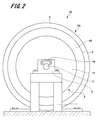
- FIG. 2 is a side view showing a hoisting machine.
- the device shown in FIG. 1 is a hoisting machine used for the elevator 100 (see FIG. 4).
- the hoisting machine 10 has a pair of pedestals 1, 1 and a spindle 3, and a hoisting machine unit 50.
- the hoisting machine 10 includes a plurality of first stators 14A constituting the first motor 7, a plurality of first rotors 15A, and a plurality of second stators 14B constituting the second motor 8.
- the second rotor 15B and the like.
- the pair of pedestals 1 and 1 are arranged so as to face one end and the other end of the spindle 3 in the axial direction. Further, the gantry 1 is provided with a support portion 4 for supporting the main shaft 3.
- the support portion 4 supports the axial end portion of the spindle 3. Further, the support portion 4 is provided with a key plate 4a for fixing the main shaft 3. The rotation and axial movement of the spindle 3 are restricted by the key plate 4a.
- a hoisting machine unit 50 is detachably attached to the spindle 3 via a fixing member 17.
- the hoisting machine unit 50 includes a housing 2, a sheave 5, and a rotating body 6.
- the housing 2 has a first support member 11, a second support member 12, and a shaft portion 13.
- the first support member 11 and the shaft portion 13 are integrally formed.
- the shaft portion 13 is formed in a substantially cylindrical shape.
- the spindle 3 is inserted into the tubular hole 13a of the shaft portion 13.
- a mounting recess 22 is formed at one end of the shaft portion 13 in the axial direction, and a second support member 12 is fixed to the other end of the shaft portion 13 in the axial direction via a fixing bolt 16.
- the mounting recess 22 is a recess formed in a substantially cylindrical shape, and one end side of the main shaft 3 in the axial direction is open.
- the outer diameter of the mounting recess 22 is formed to be larger than the outer diameter of the shaft portion 13.
- the mounting recess 22 surrounds the outer peripheral surface at one end of the spindle 3 in the axial direction.
- a fixing member 17 is interposed between the mounting recess 22 and one end of the spindle 3 in the axial direction.
- the fixing member 17 is composed of two cylindrical portions 17a having a wedge-shaped cross section and a fastening bolt 17b. Then, by tightening the fastening bolt 17b, the outer peripheral surface of the cylindrical portion 17a is pressed against the inner surface 22a of the mounting recess 22, and the inner peripheral surface of the cylindrical portion 17a is pressed against the outer peripheral surface of the main shaft 3. As a result, the housing 2 and the spindle 3 are firmly connected via the fixing member 17, and rotation and axial movement of the housing 2 are restricted.
- the fixing member 17 is not limited to the above-mentioned configuration, and various other fixing members are applied.
- first support member 11 is continuously formed on the outer peripheral surfaces of the shaft portion 13 and the mounting recess 22.
- the first support member 11 has a side surface portion 23 and a first stator support portion 24.
- the side surface portion 23 extends substantially vertically from one end in the axial direction of the mounting recess 22 toward the radial direction. Further, the side surface portion 23 is formed in a substantially disk shape.
- a first stator support portion 24 is formed at an end portion of the side surface portion 23 opposite to the mounting recess 22.
- the first stator support portion 24 has a mounting portion 25 and a side wall portion 26.
- the mounting portion 25 is formed in a substantially cylindrical shape, and projects substantially vertically from the side surface portion 23 toward the other end portion of the main shaft 3 in the axial direction.
- the mounting portion 25 is arranged concentrically with the shaft portion 13 and the mounting recess 22.
- a plurality of first stators 14A are fixed to the outer peripheral surface 25a of the mounting portion 25.
- the plurality of first stators 14A are composed of an iron core and a stator coil wound around the iron core. Then, the plurality of first stators 14A are arranged in an annular shape along the circumferential direction of the mounting portion 25.
- the side wall portion 26 projects substantially perpendicularly from one end in the axial direction on the outer peripheral surface 25a of the mounting portion 25 toward the outside in the radial direction. Further, the side wall portion 26 is formed in a substantially disk shape and covers one end portion in the axial direction of the plurality of first stators 14A fixed to the mounting portion 25.
- the second support member 12 has a side surface portion 33 and a second stator support portion 34.
- the side surface portion 33 is formed in a substantially disk shape.
- a circular opening 33a is formed at the center of the side surface portion 33 in the radial direction. The other end of the spindle 3 in the axial direction and the other end of the shaft 13 in the axial direction are inserted into the opening 33a.
- the side surface portion 33 extends outward in the radial direction from the outer peripheral surface 13b of the shaft portion 13.
- the side surface portion 33 of the second support member 12 faces the side surface portion 23 of the first support member 11 at a distance. Then, a storage space is formed by the side surface portion 23 of the first support member 11 and the side surface portion 33 of the second support member 12. In this storage space, the bearing housing 41 of the rotating body 6 described later is arranged.
- a second stator support portion 34 is formed at the end portion of the side surface portion 33 opposite to the shaft portion 13.
- the second stator support portion 34 has a mounting portion 35 and a side wall portion 36.
- the mounting portion 35 is formed in a substantially cylindrical shape, and projects substantially vertically from the side surface portion 33 toward one end portion of the main shaft 3 in the axial direction.
- the mounting portion 35 is arranged concentrically with the shaft portion 13.
- a plurality of second stators 14B are fixed to the outer peripheral surface 35a of the mounting portion 35.
- the plurality of second stators 14B are composed of an iron core and a stator coil wound around the iron core. Then, the plurality of second stators 14B are arranged in an annular shape along the circumferential direction of the mounting portion 35.
- the side wall portion 36 projects substantially vertically outward from one end in the axial direction on the outer peripheral surface 35a of the mounting portion 35 toward the outside in the radial direction.
- the side wall portion 36 is formed in a substantially disk shape and covers one end portion in the axial direction of the plurality of second stators 14B fixed to the mounting portion 35. Further, the side wall portion 36 of the second support member 12 faces the side wall portion 26 of the first support member 11 at a distance.
- a rotating body 6 is arranged between the side wall portion 36 of the second support member 12 and the side wall portion 26 of the first support member 11.
- the rotating body 6 is formed in a substantially disk shape.
- the rotating body 6 has a bearing housing 41, a connecting portion 42, and a rotor supporting portion 43.
- the bearing housing 41 is formed at the center of the rotating body 6 in the radial direction.
- the bearing housing 41 is formed in a cylindrical shape, and a support hole 41a penetrating from one end to the other end in the axial direction is formed.
- a bearing 46 is provided on the inner wall of the support hole 41a. Further, the bearing housing 41 is arranged in a storage space formed between the side surface portion 23 of the first support member 11 and the side surface portion 33 of the second support member 12.
- the rotating body 6 is rotatably supported on the outer peripheral surface 13b of the shaft portion 13 of the housing 2 via the bearing 46.
- the connecting portion 42 projects substantially vertically from the outer peripheral surface of the bearing housing 41.
- the connecting portion 42 is formed in a substantially disk shape.
- the connecting portion 42 is arranged between the first support member 11 and the second support member 12.
- the end portion of the connecting portion 42 opposite to the bearing housing 41, that is, the outer end portion in the radial direction is fixed to the plurality of first stators 14A and the second support member 12 fixed to the first support member 11. It is arranged radially outside the plurality of second stators 14B.
- the radial outer end of the connecting portion 42 is arranged between the side wall portion 26 of the first support member 11 and the side wall portion 36 of the second support member 12.
- a rotor support portion 43 is provided at the outer end portion of the connecting portion 42 in the radial direction.
- the rotor support portion 43 is formed in a substantially cylindrical shape, and protrudes from the end portion of the connecting portion 42 toward both sides in the axial direction. Further, the rotor support portion 43 is arranged on the first support member 11 and the second support member 12 on the outer side in the radial direction from the mounting portions 25 and 35.
- the inner wall surface 43a of the rotor support portion 43 faces the outer peripheral surface 25a of the mounting portion 25 of the first support member 11 and the outer peripheral surface 35a of the mounting portion 35 of the second support member 12.
- a plurality of first rotors 15A and a plurality of second rotors 15B are fixed to the inner wall surface 43a of the rotor support portion 43.
- the plurality of first rotors 15A are arranged on one end side in the axial direction of the rotor support portion 43 and face the plurality of first stators 14A.
- the plurality of second rotors 15B are arranged on the other end side in the axial direction of the rotor support portion 43 and face the plurality of second stators 14B.
- the first rotor 15A and the second rotor 15B are composed of magnets.
- the plurality of first rotors 15A and the plurality of second rotors 15B are fixed at predetermined intervals along the circumferential direction of the rotor support portion 43, respectively. Further, in the plurality of first rotors 15A and the plurality of second rotors 15B, north poles and south poles are alternately arranged along the circumferential direction of the rotor support portion 43, respectively.
- the outer peripheral surface 43b of the rotor support portion 43 is arranged outside the housing 2 in the radial direction.
- a sheave 5 is fixed to the outer peripheral surface 43b of the rotor support portion 43.
- the sheave 5 is formed in an annular shape.
- a rope connected to an elevating body such as a car or a counterweight in an elevator is wound around the sheave 5. Then, when the hoisting machine 10 is driven, the sheave 5 rotates, and the rope wound around the sheave 5 moves.
- the rotating body 6 to which the rotors 15A and 15B are fixed is rotatably supported by the housing 2.
- the axial length of the spindle 3 that supports the load applied to the hoisting machine 10 can be shortened, and the entire hoisting machine 10 can be miniaturized.
- two motors a first motor 7 and a second motor 8, can be configured in one hoisting machine 10, and a thin and large torque can be obtained.
- FIG. 3 is a cross-sectional view showing a disassembled state of the hoisting machine 10.
- first stators 14A are fixed to the attachment portion 25 of the first support member 11, and a plurality of second stators 14B are fixed to the attachment portion 35 of the second support member 12. Further, a plurality of first rotors 15A and a plurality of second rotors 15B are fixed to the rotor support portion 43 of the rotating body 6, and the bearing 46 is attached to the bearing housing 41. Further, the sheave 5 is fixed to the rotor support portion 43 of the rotating body 6.
- the rotating body 6 is rotatably attached to the shaft portion 13.
- the plurality of first stators 14A and the plurality of first rotors 15A face each other to form the first motor 7.
- the second support member 12 is fixed to the other end of the shaft portion 13 in the axial direction by the fixing bolt 16.
- the plurality of second stators 14B and the plurality of second rotors 15B face each other to form the second motor 8.
- the hoisting machine unit 50 in which the housing 2 to which the stators 14A and 14B are fixed and the rotating body 6 to which the rotors 15A and 15B are fixed can be assembled can be assembled.
- the spindle 3 is inserted into the tubular hole 13a of the shaft portion 13.
- the cylindrical portion 17a of the fixing member 17 is inserted between the mounting recess 22 of the first support member 11 and the main shaft 3, and the fastening bolt 17b is tightened.
- the outer peripheral surface of the cylindrical portion 17a is in pressure contact with the inner surface 22a of the mounting recess 22, and the inner peripheral surface of the cylindrical portion 17a is in pressure contact with the outer peripheral surface of the main shaft 3.
- the housing 2 and the spindle 3 are firmly connected via the fixing member 17. Then, by attaching the spindle 3 to the support portion 4 of the gantry 1, the assembly work of the hoisting machine 10 is completed.
- the spindle 3 can be attached / detached while the stators 14A and 14B and the rotors 15A and 15B face each other, and the hoisting machine 10 can be easily assembled.
- first support member 11 and the second support member 12 in the housing 2 which is a fixed element are arranged on both sides in the axial direction of the rotating body 6 which is a rotating element of the hoisting machine unit 50.
- the rotational operation of the rotating body 6 is not affected.
- the hoisting machine unit 50 can be easily conveyed with the spindle 3 removed from the hoisting machine unit 50.
- FIG. 4 is a schematic configuration diagram showing an elevator.
- the elevator 100 includes a car 110 that goes up and down in the hoistway 150, a hoisting machine 10, a balance weight 130, and a main rope 140.
- One end of the main rope 140 is connected to a car 110 showing an example of an elevating body, and the other end of the main rope 140 is connected to a counterweight 130 showing another example of the elevating body.
- the main rope 140 is wound around the sheave 5 (see FIG. 1) of the hoisting machine 10.
- the hoisting machine 10 is driven, the main rope 140 moves, and the car 110 and the balance weight 130 move up and down in the hoistway 150.
- the hoisting machine 10 is installed in the machine room 151 provided at the top of the hoistway 150. Further, in the machine room 151, a plurality of (two in this example) brake mechanisms 160 for braking the rotation of the sheave 5 in the hoisting machine 10 and a speed sensor 170 for detecting the rotation speed of the sheave 5 are arranged. Has been done.
- the brake mechanisms 160, 160 and the speed sensor 170 are arranged on the outer peripheral portion of the sheave 5 in the hoisting machine 10. Further, in the example shown in FIG. 4, one of the two brake mechanisms 160 and 160 is arranged on one side of the gantry 1, and the other brake mechanism 160 is arranged on the other side of the gantry 1. There is. Further, the speed sensor 170 is arranged at the lower end portion in the vertical direction on the outer peripheral portion of the sheave 5. Then, the speed sensor 170 comes into contact with the outer peripheral portion of the sheave 5 and detects the rotational speed of the sheave 5.
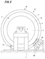
- FIG. 5 is a side view showing another example of the installation position of the brake mechanism. As shown in FIG. 5, the two brake mechanisms 160 and 160 may be arranged together on one side of the gantry 1. Further, in the example shown in FIG. 5, the speed sensor 170 contacts the rotating body 6 in the hoisting machine 10 and detects the rotating speed of the sheave 5 from the rotating speed of the rotating body 6.
- the brake mechanism 160 and the speed sensor 170 can be installed at arbitrary positions on the outer peripheral portions of the sheave 5 and the rotating body 6.
- the brake mechanism 160 and the speed sensor 170 are preferably arranged below the main shaft 3 of the hoisting machine 10 in the vertical direction.
- FIG. 6 and 7 show the brake mechanism 160, FIG. 6 shows the state before the brake mechanism operates, and FIG. 7 shows the state in which the brake mechanism operates.
- the brake mechanism 160 has an electromagnetic core 161 provided with an electromagnetic coil, an amateur 162, and a pair of brake levers 163A and 163B.
- the electromagnetic core 161 and the amateur 162 are arranged on the outer side in the radial direction from the sheave 5.
- the magnetic attraction surface of the electromagnetic core 161 faces the axial direction of the sheave 5.
- the amateur 162 is arranged so as to face the magnetic attraction surface of the electromagnetic core 161.
- the amateur 162 is urged in a direction away from the electromagnetic core 161 by an urging member (not shown).
- the first brake lever 163A is connected to the electromagnetic core 161 and the second brake lever 163B is connected to the amateur 162.
- One end of the first brake lever 163A is connected to a surface of the electromagnetic core 161 opposite to the magnetic attraction surface.
- One end of the second brake lever 163B is connected to a surface of the amateur 162 opposite to the surface facing the magnetic attraction surface.
- the first brake lever 163A protrudes from the electromagnetic core 161 toward the sheave 5, and the second brake lever 163B protrudes from the amateur 162 toward the sheave 5.
- the other end of the first brake lever 163A faces the first braking surface 5a, which is a side surface portion of the sheave 5 on one end side in the axial direction.
- the other end of the second brake lever 163B faces the second braking surface 5b, which is a side surface portion of the sheave 5 on the other end side in the axial direction.
- brake shoes 164 are provided at the other ends of the first brake lever 163A and the second brake lever 163B at positions facing the side surface of the sheave 5. Further, the first brake lever 163A and the second brake lever 163B are rotatably supported by the rotation shaft 165, respectively. The rotating shaft 165 is provided at an intermediate portion between the first brake lever 163A and the second brake lever 163B.
- the electromagnetic coil of the electromagnetic core 161 is energized, and the amateur 162 is attracted to the magnetic attraction surface of the electromagnetic core 161 against the urging force of the urging member. Further, the first brake lever 163A and the second brake lever 163B rotate about the rotation shaft 165. Then, the two brake shoes 164 and 164 are separated from the first braking surface 5a and the second braking surface 5b of the sheave 5.
- the energization of the electromagnetic coil is stopped and the magnetism of the electromagnetic core 161 is erased. Therefore, as shown in FIG. 7, the electromagnetic core 161 and the amateur 162 are urged by the urging member and move in a direction away from each other. Further, the first brake lever 163A and the second brake lever 163B rotate about the rotation shaft 165. Then, the two brake shoes 164 and 164 are pressed against the first braking surface 5a and the second braking surface 5b of the sheave 5. That is, the sheave 5 is sandwiched by the first brake lever 163A and the second brake lever 163B. As a result, the rotational operation of the sheave 5 and the rotating body 6 of the hoisting machine 10 is braked.
- the brake mechanism is not limited to the above-mentioned configuration, and various other configurations can be applied.
- FIG. 8 is a schematic configuration diagram showing an elevator according to the second embodiment
- FIG. 9 is a plan view showing the elevator according to the second embodiment.
- the elevator according to the second embodiment is a so-called multi-car elevator in which a car, which is a plurality of elevating bodies, moves in the same hoistway.
- the parts common to the elevator 100 and the hoisting machine 10 according to the first embodiment are designated by the same reference numerals, and duplicate description will be omitted.
- the elevator 200 includes a plurality of pairs (3 pairs in this example) of the car 210A, 210B, 210C indicating an elevating body, a first hoisting machine 220, and a second hoisting machine. It includes a machine 230, a first lower pulley 240, and a second lower pulley 250. Further, the elevator 200 includes three first main ropes 260A, 260B, 260C and second main ropes 270A, 270B, and 270C according to the pair of the car 210.
- first lower pulley 240 and the second lower pulley 250 are also provided in three sets according to the pair of the car 210.
- the first hoisting machine 220 and the second hoisting machine 230 have three hoisting machine units 50A, 50B, and 50C, respectively, corresponding to the number of the first main rope 260 and the second main rope 270. ..
- the first hoisting machine 220 and the second hoisting machine 230 are arranged at the top of the hoistway 280, and the first lower pulley 240 and the second lower pulley 250 are arranged at the lower part of the hoistway 280. Further, the first hoisting machine 220 and the first lower pulley 240 face each other in the elevating direction, and the second hoisting machine 230 and the second lower pulley 250 face each other in the elevating direction.
- the first main rope 260A, 260B, 260C and the second main rope 270A, 270B, 270C are formed in an endless shape in which both ends are connected.
- the first main rope 260 is stretched on the first hoisting machine 220 and the first lower pulley 240, and the second main rope 270 is stretched on the second hoisting machine 230 and the second lower pulley 250. There is.
- the car 210A is connected to the first main rope 260A and the second main rope 270A
- the car 210B is connected to the first main rope 260B and the second main rope 270B
- the car 210C is connected to the first main rope 260C and the second main rope 270C.
- the first hoisting machine 220 and the second hoisting machine 230 By driving the first hoisting machine 220 and the second hoisting machine 230, the first main rope 260A, 260B, 260C and the second main rope 270A, 270B, 270C move, and three pairs of car 210A, 210B. , 210C move in the hoistway 280. Further, when the three pairs of cars 210A, 210B and 210C pass through the first hoisting machine 220, the second hoisting machine 230, the first lower pulley 240 and the second lower pulley 250, their moving directions are reversed. To do. As a result, the three pairs of cars 210A, 210B, and 210C move on the hoistway 280.
- FIG. 10 is a cross-sectional view showing the first hoisting machine 220.
- the hoisting machine 220 has a pair of mounts 221 and 221, a spindle 223, and three hoisting machine units 50A, 50B, and 50C.
- the three hoisting machine units 50A, 50B, and 50C each have the same configuration as the hoisting machine unit 50 according to the first embodiment.
- the pair of pedestals 221 and 221 are arranged so as to face one end and the other end of the spindle 223 in the axial direction.
- the gantry 1 is provided with a support portion 224 for supporting the main shaft 223.
- the support portion 224 supports the axial end portion of the spindle 223.
- the support portion 224 is provided with a key plate 224a for fixing the main shaft 223. The rotation and axial movement of the spindle 223 are restricted by the key plate 224a.
- the first hoisting machine unit 50A is arranged on one end side of the spindle 223 in the axial direction
- the third hoisting machine unit 50C is arranged on the other end side of the spindle 223 in the axial direction.
- the second hoisting machine unit 50B is arranged between the first hoisting machine unit 50A and the third hoisting machine unit 50C.
- the tubular holes 13a of the shaft portion 13 of each hoisting machine unit 50A, 50B, 50C are parallel to the axial direction of the spindle 223. It communicates linearly with.
- the spindle 223 is inserted into the cylinder hole 13a of the shaft portion 13 of the three hoisting machine units 50A, 50B, and 50C. Then, the housing 2 of the hoisting machine units 50A, 50B, 50C is fixed to one main shaft 223 common to the fixing members 17A, 17B, 17C.
- the rotating body 6 which is a rotating element is sandwiched between the first support member 11 and the second support member 12 in the housing 2 which is a fixed element. Since both sides of the hoisting machine unit 50 in the axial direction are the first support member 11 and the second support member 12 which are fixing elements, other members are arranged on both sides of the hoisting machine unit 50 in the axial direction. However, it does not affect the rotational operation of the rotating body 6.
- the first hoisting machine unit 50A and the second hoisting machine unit 50B can be arranged close to each other, and the second hoisting machine unit 50B and the third hoisting machine unit 50C can be arranged close to each other. Can be done.
- the axial length of the spindle 223 penetrating the three hoisting machine units 50A, 50B, and 50C can be shortened, and the entire hoisting machine 220 can be miniaturized.
- the three hoisting machine units 50A, 50B, and 50C can be driven independently.
- the three pairs of cars 210A, 210B, and 210C can be moved up and down independently.
- the number of hoisting machine units 50 is not limited to three, but is appropriately set according to the number of car 210s.
- the elevator 200 and the hoisting machine 220 having such a configuration can also obtain the same effects as the elevator 100 and the hoisting machine 10 according to the first embodiment described above.
- FIG. 11 is a cross-sectional view showing the hoisting machine according to the third embodiment.
- a plurality of hoisting machine units are arranged, and a plurality of hoisting machine units are further arranged. It is a combination.
- the parts common to the hoisting machine 10 according to the first embodiment and the hoisting machine 220 according to the second embodiment are designated by the same reference numerals, and duplicate description will be omitted.
- the hoisting machine 310 has a pair of mounts 221 and 221, a spindle 223, and three hoisting machine units 50A, 50B, and 50C.
- the three hoisting machine units 50A, 50B, and 50C each have the same configuration as the hoisting machine unit 50 according to the first embodiment.
- the first hoisting machine unit 50A is arranged on one end side of the spindle 223 in the axial direction
- the third hoisting machine unit 50C is arranged on the other end side of the spindle 223 in the axial direction.
- the second hoisting machine unit 50B is arranged between the first hoisting machine unit 50A and the third hoisting machine unit 50C. Then, the main shaft 223 is inserted into the tubular hole 13a of the shaft portion 13 of the three hoisting machine units 50A, 50B, 50C, and the housing 2 of the hoisting machine units 50A, 50B, 50C has the fixing members 17A, 17B. , 17C fixed to the spindle 223.
- the second support member 12 of the first hoisting machine unit 50A and the first support member 11 of the second hoisting machine unit 50B are connected by the housing connecting member 311. Then, the rotating body 6 of the first hoisting machine unit 50A and the rotating body 6 of the second hoisting machine unit 50B are connected by the rotating body coupling member 312 at the rotor support portion 43 exposed from the housing 2. Has been done.
- the second support member 12 of the second hoisting machine unit 50B and the first support member 11 of the third hoisting machine unit 50C are connected by the housing connecting member 313.
- the rotating body 6 of the second hoisting machine unit 50B and the rotating body 6 of the third hoisting machine unit 50C are connected by the rotating body coupling member 314 at the rotor support portion 43 exposed from the housing 2. Has been done. As a result, the rotating bodies 6 of the three hoisting machine units 50A, 50B, and 50C rotate together.
- the torque of the hoisting machine 310 can be easily increased.
- the number of hoisting machine units 50 is not limited to three, and is appropriately set according to the required torque, the load capacity of the elevating body, and the load.
- the hoisting machine 310 having such a configuration can also obtain the same operation and effect as the hoisting machine 10 according to the first embodiment described above.
- FIG. 12 is a cross-sectional view showing the hoisting machine according to the fourth embodiment.
- the hoisting machine 410 according to the fourth embodiment is different from the hoisting machine 310 according to the third embodiment in that the configuration of the hoisting machine unit is changed and a braking disc is provided. It is a thing.
- the parts common to the hoisting machine 10 according to the first embodiment and the hoisting machine 310 according to the third embodiment are designated by the same reference numerals, and duplicate description will be omitted.
- the hoisting machine 410 has a pair of mounts 221 and 221, a spindle 223, three hoisting machine units 60A, 60B, 60C, and a braking disc 412.
- the hoisting machine units 60A, 60B, and 60C each have a housing 62 and a rotating body 66. Then, each housing 62 and the rotating body 66 are connected by a coupling member 311, 312, 313, 314.
- the housing 62 has a first support member 71, a second support member 72, and a shaft portion 73. Since the configuration of the second support member 72 is the same as that of the second support member 12 according to the first embodiment, the description thereof will be omitted.
- the first support member 71 is fixed to one end of the shaft portion 73 in the axial direction via a fixing bolt 18. That is, in the hoisting machine unit 60 according to the fourth embodiment, the shaft portion 73 and the first support member 71 are configured as separate members. Since the other configurations are the same as those of the shaft portion 13 and the first support member 11 according to the first embodiment, the description thereof will be omitted.
- a sheave 75 is integrally formed with the rotor support portion 74 of the rotating body 66 in the first hoisting machine unit 60A and the second hoisting machine unit 60B.
- a sheave is not formed on the rotor support portion 74 of the rotating body 66 in the third winding machine unit 60C. In this way, the width of the sheave and the number of grooves can be freely combined according to the required torque and the number of main ropes.
- a braking disc 412 is fixed to the rotor support portion 74 of the third winding machine unit 60C by a mounting bolt 19.
- the braking disc 412 is formed in a substantially disk shape. Then, the braking disc 412 is sandwiched by a brake mechanism (not shown), so that the rotational operation of the rotating bodies 66 of the three hoisting machine units 60A, 60B, and 60C is braked.
- the hoisting machine 410 having such a configuration also obtains the same effects as those of the hoisting machine 10 according to the first embodiment and the hoisting machine 310 according to the third embodiment described above. Can be done.
- FIG. 13 is a cross-sectional view showing the hoisting machine according to the fifth embodiment.
- the hoisting machine 510 according to the fifth embodiment is different from the hoisting machine 10 according to the first embodiment in the installation position of the housing and the sheave. Therefore, the same reference numerals are given to the parts common to the hoisting machine 10 according to the first embodiment, and duplicate description will be omitted.
- the hoisting machine 510 has a pair of pedestals 1, 1 and a spindle 3, and a hoisting machine unit 550. Further, the hoisting machine 510 has a plurality of stators 14 and a plurality of rotors 15. The hoisting machine unit 550 is attached to the spindle 3 by a fixing member 17.
- the hoisting machine unit 550 includes a housing 502, a sheave 505, a rotating body 506, and a braking disc 512.
- the housing 502 has a support member 511 and a shaft portion 513.
- the support member 511 and the shaft portion 513 are integrally formed.
- a plurality of stators 14 are fixed to the support member 511. Since the support member 511 and the shaft portion 513 have the same configuration as the first support member 11 and the shaft portion 13 according to the first embodiment, the description thereof will be omitted. That is, the housing 502 according to the fifth embodiment has a configuration in which the second support member 12 is removed from the housing 2 according to the first embodiment.
- a rotating body 506 is rotatably supported on the outer peripheral surface 513b of the shaft portion 513 via a bearing 46.
- the rotating body 506 includes a bearing housing 541 provided with a bearing 46, a connecting portion 542, and a rotor supporting portion 543. Since the structure of the bearing housing 541 has the same structure as that of the bearing housing 41 according to the first embodiment, the description thereof will be omitted.
- the connecting portion 542 projects substantially vertically from the outer peripheral surface of the bearing housing 541.
- the connecting portion 542 is formed in a substantially disk shape.
- a rotor support portion 543 is provided at the outer end portion of the connecting portion 542 in the radial direction.
- the rotor support portion 543 is formed in a substantially cylindrical shape, and protrudes from the end portion of the connecting portion 542 toward one end portion in the axial direction.
- a plurality of rotors 15 are fixed to the inner wall surface 543a of the rotor support portion 543. Then, the plurality of rotors 15 face the plurality of stators 14 fixed to the support member 511.
- a sheave 505 is arranged on one surface of the connecting portion 542 on the other end side of the main shaft 3 in the axial direction. Further, a disc-shaped braking disc 512 is arranged at an end of the sheave 505 opposite to the connecting portion 542. The sheave 505 and the braking disc 512 are fixed to the connecting portion 542 by mounting bolts 518.
- the hoisting machine unit 550 can be detachably attached to the spindle 3, and assembly and transfer work can be easily performed.
- the hoisting machine 510 having such a configuration can also obtain the same operation and effect as the hoisting machine 10 according to the first embodiment described above.
Abstract
巻上機は、主軸と、巻上機ユニットと、を備えている。巻上機ユニットは、軸部と、支持部材と、複数の固定子と、回転体と、複数の回転子と、綱車と、を有している。軸部は、主軸が挿入される筒孔を有し、主軸に固定される。支持部材は、軸部の外周面から半径方向の外側に向けて延在する。複数の固定子は、支持部材に固定される。回転体は、軸部に回転可能に支持される。複数の回転子は、回転体に固定される。
Description
本発明は、乗りかごや釣合おもり等の昇降体を昇降動作させる巻上機及び、この巻上機を備えたエレベーターに関するものである。
従来の巻上機としては、例えば、特許文献1に記載されているようなものがある。特許文献1には、ハウジングの前面に開口した凹所に支持軸を突設し、支持軸に回転体を枢着してハウジングの凹所に嵌合状態に配置することが記載されている。また、特許文献1には、ハウジングの凹所の開口側と同側に開口した回転体の凹部に制動機を設け、また支持軸の突出端、すなわちハウジングの前面側に駆動綱車を設けることが記載されている。
しかしながら、特許文献1に記載された技術では、主軸を示す支持軸の軸方向の一端部にステータを支持するハウジングを固定し、支持軸の軸方向の他端部に回転子を支持する回転体を回転可能に支持している。そのため、特許文献1に記載された技術では、主軸の軸方向の長さが長くなり、巻上機全体の小型化を図ることが困難なものとなっていた。
本目的は、上記の問題点を考慮し、小型化を図ることができる巻上機及びエレベーターを提供することにある。
上記課題を解決し、目的を達成するため、巻上機は、主軸と、主軸に着脱可能に取り付けられる巻上機ユニットと、を備えている。
巻上機ユニットは、軸部と、支持部材と、複数の固定子と、回転体と、複数の回転子と、綱車と、を有している。
軸部は、主軸が挿入される筒孔を有し、主軸に固定される。支持部材は、軸部の外周面から半径方向の外側に向けて延在する。複数の固定子は、支持部材に固定される。回転体は、軸部に回転可能に支持される。複数の回転子は、回転体に固定され、複数の固定子と対向する。綱車は、回転体に取り付けられる。
巻上機ユニットは、軸部と、支持部材と、複数の固定子と、回転体と、複数の回転子と、綱車と、を有している。
軸部は、主軸が挿入される筒孔を有し、主軸に固定される。支持部材は、軸部の外周面から半径方向の外側に向けて延在する。複数の固定子は、支持部材に固定される。回転体は、軸部に回転可能に支持される。複数の回転子は、回転体に固定され、複数の固定子と対向する。綱車は、回転体に取り付けられる。
また、エレベーターは、昇降路内を昇降する昇降体と、昇降体に接続される主ロープと、主ロープを巻き掛けることにより昇降体を昇降させる巻上機と、を備えている。また、巻上機は、上述した巻上機が用いられる。
上記構成の巻上機及びエレベーターによれば、小型化を図ることができる。
以下、巻上機及びエレベーターの実施の形態例について、図1~図13を参照して説明する。なお、各図において共通の部材には、同一の符号を付している。
1.第1の実施の形態例
1-1.巻上機の構成
まず、第1の実施の形態例(以下、「本例」という。)にかかる巻上機の構成について、図1及び図2を参照して説明する。
図1は、巻上機を示す断面図、図2は、巻上機を示す側面図である。
1-1.巻上機の構成
まず、第1の実施の形態例(以下、「本例」という。)にかかる巻上機の構成について、図1及び図2を参照して説明する。
図1は、巻上機を示す断面図、図2は、巻上機を示す側面図である。
図1に示す装置は、エレベーター100(図4参照)に用いられる巻上機である。図1に示すように、巻上機10は、一対の架台1、1と、主軸3と、巻上機ユニット50と、を有している。また、巻上機10は、第1モータ7を構成する複数の第1固定子14Aと、複数の第1回転子15Aと、第2モータ8を構成する複数の第2固定子14Bと、複数の第2回転子15Bと、を有している。
図1及び図2に示すように、一対の架台1、1は、主軸3の軸方向の一端部と他端部に対向して配置されている。また、架台1には、主軸3を支持する支持部4が設けられている。
支持部4は、主軸3の軸方向の端部を支持する。また、支持部4には、主軸3を固定するキープレート4aが設けられている。主軸3は、キープレート4aにより回転及び軸方向への移動が規制される。主軸3には、固定部材17を介して巻上機ユニット50が着脱可能に取り付けられる。
[巻上機ユニット]
巻上機ユニット50は、筐体2と、綱車5と、回転体6と、を有している。筐体2は、第1支持部材11と、第2支持部材12と、軸部13と、を有している。第1支持部材11と軸部13は、一体に形成されている。軸部13は、略円筒状に形成されている。軸部13の筒孔13aには、主軸3が挿入される。軸部13の軸方向の一端部には、取付凹部22が形成され、軸部13の軸方向の他端部には、第2支持部材12が固定ボルト16を介して固定されている。
巻上機ユニット50は、筐体2と、綱車5と、回転体6と、を有している。筐体2は、第1支持部材11と、第2支持部材12と、軸部13と、を有している。第1支持部材11と軸部13は、一体に形成されている。軸部13は、略円筒状に形成されている。軸部13の筒孔13aには、主軸3が挿入される。軸部13の軸方向の一端部には、取付凹部22が形成され、軸部13の軸方向の他端部には、第2支持部材12が固定ボルト16を介して固定されている。
取付凹部22は、略円筒状に形成された凹部であり、主軸3の軸方向の一端部側が開口している。取付凹部22の外径は、軸部13の外径よりも大きく形成されている。そして、取付凹部22は、主軸3の軸方向の一端部における外周面を囲む。
取付凹部22と主軸3の軸方向の一端部との間には、固定部材17が介在される。固定部材17は、断面形状がくさび状に形成された2つの円筒部17aと、締結ボルト17bから構成されている。そして、締結ボルト17bを締め付けることで、円筒部17aの外周面が取付凹部22の内面22aに圧接し、円筒部17aの内周面が主軸3の外周面に圧接する。これにより、筐体2と主軸3が固定部材17を介して強固に結合され、筐体2における回転及び軸方向への移動が規制される。
固定部材17としては、上述した構成に限定されるものではなく、その他各種の固定部材が適用される。
また、軸部13及び取付凹部22の外周面には、第1支持部材11が連続して形成されている。第1支持部材11は、側面部23と、第1固定子支持部24と、を有している。側面部23は、取付凹部22の軸方向の一端部から略垂直に半径方向のに向けて延在している。また、側面部23は、略円板状に形成されている。側面部23における取付凹部22とは反対側の端部には、第1固定子支持部24が形成されている。
第1固定子支持部24は、取付部25と、側壁部26とを有している。取付部25は、略円筒状に形成されており、側面部23から主軸3の軸方向の他端部に向けて略垂直に突出している。取付部25は、軸部13及び取付凹部22と同心円状に配置される。取付部25の外周面25aには、複数の第1固定子14Aが固定される。複数の第1固定子14Aは、鉄芯とこの鉄芯に巻回されたステータコイルにより構成される。そして、複数の第1固定子14Aは、取付部25の周方向に沿って環状に配置される。
側壁部26は、取付部25の外周面25aにおける軸方向の一端部から略垂直に半径方向の外側に向けて突出している。また、側壁部26は、略円板状に形成され、取付部25に固定された複数の第1固定子14Aにおける軸方向の一端部を覆う。
第2支持部材12は、側面部33と、第2固定子支持部34と、を有している。側面部33は、略円板状に形成されている。側面部33の半径方向の中心には、円形の開口部33aが形成されている。開口部33aには、主軸3の軸方向の他端部及び軸部13の軸方向の他端部が挿入される。そして、側面部33は、軸部13の外周面13bから半径方向の外側に向けて延在している。
また、第2支持部材12の側面部33は、第1支持部材11の側面部23と間隔を空けて対向する。そして、第1支持部材11の側面部23と第2支持部材12の側面部33により、収納空間が形成される。この収納空間には、後述する回転体6の軸受ハウジング41が配置される。
側面部33における軸部13とは反対側の端部には、第2固定子支持部34が形成されている。第2固定子支持部34は、取付部35と、側壁部36とを有している。取付部35は、略円筒状に形成されており、側面部33から主軸3の軸方向の一端部に向けて略垂直に突出している。取付部35は、軸部13と同心円状に配置される。取付部35の外周面35aには、複数の第2固定子14Bが固定される。複数の第2固定子14Bは、第1固定子14Aと同様に、鉄芯とこの鉄芯に巻回されたステータコイルにより構成される。そして、複数の第2固定子14Bは、取付部35の周方向に沿って環状に配置される。
側壁部36は、取付部35の外周面35aにおける軸方向の一端部から略垂直に半径方向の外側に向けて突出している。側壁部36は、略円板状に形成され、取付部35に固定された複数の第2固定子14Bにおける軸方向の一端部を覆う。また、第2支持部材12の側壁部36は、第1支持部材11の側壁部26と間隔を空けて対向する。この第2支持部材12の側壁部36と第1支持部材11の側壁部26との間には、回転体6が配置される。
次に、回転体6について説明する。回転体6は、略円板状に形成されている。回転体6は、軸受ハウジング41と、接続部42と、回転子支持部43とを有している。
軸受ハウジング41は、回転体6の半径方向の中心部に形成されている。軸受ハウジング41は、円筒状に形成されており、軸方向の一端から他端にかけて貫通する支持孔41aが形成されている。支持孔41aの内壁には、軸受46が設けられている。また、軸受ハウジング41は、第1支持部材11の側面部23と第2支持部材12の側面部33の間に形成された収納空間に配置される。そして、回転体6は、軸受46を介して筐体2の軸部13の外周面13bに回転可能に支持されている。
接続部42は、軸受ハウジング41の外周面から略垂直に突出している。接続部42は、略円板状に形成されている。接続部42は、第1支持部材11と第2支持部材12の間に配置される。接続部42における軸受ハウジング41とは反対側の端部、すなわち半径方向の外側の端部は、第1支持部材11に固定された複数の第1固定子14A及び第2支持部材12に固定された複数の第2固定子14Bよりも半径方向の外側に配置される。そして、接続部42の半径方向の外側の端部は、第1支持部材11の側壁部26と第2支持部材12の側壁部36の間に配置される。この接続部42の半径方向の外側の端部には、回転子支持部43が設けられている。
回転子支持部43は、略円筒状に形成されており、接続部42の端部から軸方向の両側に向けて突出している。また、回転子支持部43は、第1支持部材11及び第2支持部材12に取付部25、35よりも半径方向の外側に配置される。そして、回転子支持部43の内壁面43aは、第1支持部材11の取付部25の外周面25a及び第2支持部材12の取付部35の外周面35aと対向する。
また、回転子支持部43の内壁面43aには、複数の第1回転子15Aと複数の第2回転子15Bが固定されている。複数の第1回転子15Aは、回転子支持部43における軸方向の一端部側に配置されて、複数の第1固定子14Aと対向する。複数の第2回転子15Bは、回転子支持部43における軸方向の他端部側に配置されて、複数の第2固定子14Bと対向する。
第1回転子15A及び第2回転子15Bは、磁石により構成されている。複数の第1回転子15Aと複数の第2回転子15Bは、それぞれ回転子支持部43の周方向に沿って所定の間隔を空けて固定されている。また、複数の第1回転子15Aと複数の第2回転子15Bは、それぞれ回転子支持部43の周方向に沿ってN極とS極が交互に配置される。
回転子支持部43の外周面43bは、筐体2よりも半径方向の外側に配置されている。回転子支持部43の外周面43bには、綱車5が固定されている。綱車5は、円環状に形成されている。この綱車5には、エレベーターにおける乗りかごや釣合おもり等の昇降体に接続されたロープが巻き掛けられる。そして、巻上機10が駆動することで、綱車5が回転し、綱車5に巻き掛けられたロープが移動する。
本例の巻上機10によれば、回転子15A、15Bが固定された回転体6を筐体2によって回転可能に支持している。これにより、巻上機10に加わる荷重を支持する主軸3の軸方向の長さを短くすることができ、巻上機10全体の小型化を図ることができる。
さらに、1つの巻上機10に第1モータ7と第2モータ8の2つのモータを構成することができ、薄型で大きなトルクを得ることができる。
1-2.巻上機の組立作業例
次に、上述した構成を有する巻上機10の組立作業例について図3を参照して説明する。
図3は、巻上機10の分解状態を示す断面図である。
次に、上述した構成を有する巻上機10の組立作業例について図3を参照して説明する。
図3は、巻上機10の分解状態を示す断面図である。
まず、第1支持部材11の取付部25に複数の第1固定子14Aを固定すると共に、第2支持部材12の取付部35に複数の第2固定子14Bを固定する。また、回転体6の回転子支持部43に複数の第1回転子15A及び複数の第2回転子15Bを固定し、軸受ハウジング41に軸受46を取り付ける。さらに、回転体6の回転子支持部43に綱車5を固定する。
次に、回転体6を軸部13に回転可能に取り付ける。これにより、複数の第1固定子14Aと複数の第1回転子15Aが対向し、第1モータ7が構成される。そして、軸部13の軸方向の他端部に第2支持部材12を固定ボルト16により固定する。これにより、複数の第2固定子14Bと複数の第2回転子15Bが対向し、第2モータ8が構成される。その結果、固定子14A、14Bが固定された筐体2と、回転子15A、15Bが固定された回転体6が一体となった巻上機ユニット50を組み立てることができる。
図3に示すように、軸部13の筒孔13aに主軸3を挿入する。そして、第1支持部材11の取付凹部22と主軸3の間に固定部材17の円筒部17aを挿入し、締結ボルト17bを締め込む。これにより、円筒部17aの外周面が取付凹部22の内面22aに圧接し、円筒部17aの内周面が主軸3の外周面に圧接する。その結果、筐体2と主軸3が固定部材17を介して強固に結合される。そして、主軸3を架台1の支持部4に取り付けることで、巻上機10の組立作業が完了する。
ここで、従来の巻上機では、筐体及び回転体を主軸から取り外すと、筐体と回転体が分離し、固定子と回転子も分離していた。そのため、従来の巻上機では、固定子と回転子との位置合わせ作業が煩雑なものとなっていた。さらに、分解状態での搬送作業が困難なものとなっていた。
これに対して、本例の巻上機10では、筐体2から主軸3を分解しても、筐体2と回転体6は分離しない。そのため、固定子14A、14Bと回転子15A、15Bが対向した状態で主軸3の着脱作業を行うことができ、巻上機10の組立作業を容易に行うことができる。
また、巻上機ユニット50の回転要素である回転体6における軸方向の両側には、固定要素である筐体2における第1支持部材11と第2支持部材12が配置されている。これにより、巻上機ユニット50の軸方向の両側に他の部材を配置しても、回転体6の回転動作に影響を与えることがない。その結果、巻上機ユニット50から主軸3を取り外した状態で、巻上機ユニット50を容易に搬送することができる。
1-3.エレベーターの構成例
次に、上述した構成を有する巻上機10を備えたエレベーターの一例について図4から図6を参照して説明する。
図4は、エレベーターを示す概略構成図である。
次に、上述した構成を有する巻上機10を備えたエレベーターの一例について図4から図6を参照して説明する。
図4は、エレベーターを示す概略構成図である。
図4に示すように、エレベーター100は、昇降路150内を昇降する乗りかご110と、巻上機10と、釣合おもり130と、主ロープ140とを備えている。主ロープ140の一端は、昇降体の一例を示す乗りかご110に接続され、主ロープ140の他端は、昇降体の他の例を示す釣合おもり130に接続される。そして、主ロープ140は、巻上機10の綱車5(図1参照)に巻き掛けられる。巻上機10が駆動することで、主ロープ140が移動し、乗りかご110及び釣合おもり130が昇降路150内を昇降する。
巻上機10は、昇降路150の頂部に設けられた機械室151に設置される。また、機械室151には、巻上機10における綱車5の回転を制動する複数(本例では、2つ)のブレーキ機構160と、綱車5の回転速度を検出する速度センサ170が配置されている。
ブレーキ機構160、160及び速度センサ170は、巻上機10における綱車5の外周部に配置されている。また、図4に示す例では、2つのブレーキ機構160、160のうち一つのブレーキ機構160は、架台1の一側に配置され、他方のブレーキ機構160は、架台1の他側に配置されている。また、速度センサ170は、綱車5の外周部において上下方向の下端部に配置されている。そして、速度センサ170は、綱車5の外周部に当接し、綱車5の回転速度を検出する。
なお、2つのブレーキ機構160、160の配置は、これに限定されるものではない。図5は、ブレーキ機構の設置位置の他の例を示す側面図である。図5に示すように、2つのブレーキ機構160、160を架台1の一側にまとめて配置してよい。また、図5に示す例では、速度センサ170は、巻上機10における回転体6に接触し、回転体6の回転速度から綱車5の回転速度を検出する。
このように、ブレーキ機構160及び速度センサ170は、綱車5及び回転体6の外周部において任意の位置に設置できるものである。なお、ブレーキ機構160及び速度センサ170は、巻上機10の主軸3よりも上下方向の下方に配置されることが好ましい。
[ブレーキ機構]
図6及び図7は、ブレーキ機構160を示すもので、図6は、ブレーキ機構が作動する前の状態を示し、図7は、ブレーキ機構が作動した状態を示している。
図6に示すように、ブレーキ機構160は、電磁コイルが設けられた電磁コア161と、アマチュア162と、一対のブレーキレバー163A、163Bとを有している。
図6及び図7は、ブレーキ機構160を示すもので、図6は、ブレーキ機構が作動する前の状態を示し、図7は、ブレーキ機構が作動した状態を示している。
図6に示すように、ブレーキ機構160は、電磁コイルが設けられた電磁コア161と、アマチュア162と、一対のブレーキレバー163A、163Bとを有している。
電磁コア161及びアマチュア162は、綱車5よりも半径方向の外側に配置されている。電磁コア161の磁気吸着面は、綱車5の軸方向を向いている。また、アマチュア162は、電磁コア161の磁気吸着面に対向して配置されている。アマチュア162は、不図示の付勢部材により、電磁コア161から離反する向きに付勢されている。
一対のブレーキレバー163A、163Bのうち第1ブレーキレバー163Aは、電磁コア161に接続され、第2ブレーキレバー163Bは、アマチュア162に接続されている。第1ブレーキレバー163Aの一端は、電磁コア161における磁気吸着面とは反対側の面に接続されている。第2ブレーキレバー163Bの一端は、アマチュア162における磁気吸着面と対向する面とは反対側の面に接続されている。
第1ブレーキレバー163Aは、電磁コア161から綱車5に向けて突出し、第2ブレーキレバー163Bは、アマチュア162から綱車5に向けて突出している。また、第1ブレーキレバー163Aの他端は、綱車5における軸方向の一端側の側面部である第1制動面5aと対向している。そして、第2ブレーキレバー163Bの他端は、綱車5における軸方向の他端側の側面部である第2制動面5bと対向している。
さらに、第1ブレーキレバー163A及び第2ブレーキレバー163Bの他端における綱車5の側面部と対向する箇所には、それぞれブレーキシュー164が設けられている。また、第1ブレーキレバー163A及び第2ブレーキレバー163Bは、それぞれ回動軸165により回動可能に支持されている。回動軸165は、第1ブレーキレバー163A及び第2ブレーキレバー163Bにおける中間部に設けられている。
巻上機10の運転時には、電磁コア161の電磁コイルが通電されて、アマチュア162は、付勢部材の付勢力に抗して電磁コア161の磁気吸着面に吸着される。また、第1ブレーキレバー163A及び第2ブレーキレバー163Bは、回動軸165を中心に回動する。そして、2つのブレーキシュー164、164は、綱車5の第1制動面5a及び第2制動面5bから離間する。
巻上機10の停止時には、電磁コイルへの通電が停止し、電磁コア161の磁性が消去される。そのため、図7に示すように、電磁コア161及びアマチュア162は、付勢部材に付勢されて、互いに離反する方向に移動する。また、第1ブレーキレバー163A及び第2ブレーキレバー163Bは、回動軸165を中心に回動する。そして、2つのブレーキシュー164、164は、綱車5の第1制動面5a及び第2制動面5bに圧される。すなわち、綱車5は、第1ブレーキレバー163A及び第2ブレーキレバー163Bによって挟持される。これにより、巻上機10の綱車5及び回転体6の回転動作が制動される。
なお、ブレーキ機構としては、上述した構成に限定されるものではなく、その他各種の構成が適用できるものである。
2.第2の実施の形態例
次に、図8から図10を参照して第2の実施の形態例にかかるエレベーター及び巻上機について説明する。
図8は、第2の実施の形態例にかかるエレベーターを示す概略構成図、図9は、第2の実施の形態例にかかるエレベーターを示す平面図である。
次に、図8から図10を参照して第2の実施の形態例にかかるエレベーター及び巻上機について説明する。
図8は、第2の実施の形態例にかかるエレベーターを示す概略構成図、図9は、第2の実施の形態例にかかるエレベーターを示す平面図である。
この第2の実施の形態例にかかるエレベーターは、複数の昇降体である乗りかごが同一の昇降路内を移動する、いわゆるマルチカーエレベーターである。なお、第1の実施の形態例にかかるエレベーター100及び巻上機10と共通する部分には、同一の符号を付して重複した説明を省略する。
図8及び図9に示すように、エレベーター200は、昇降体を示す複数対(本例では、3対)の乗りかご210A、210B、210Cと、第1巻上機220と、第2巻上機230と、第1下部プーリ240と、第2下部プーリ250を備えている。また、エレベーター200は、乗りかご210の対に合わせて3つの第1主ロープ260A、260B、260Cと、第2主ロープ270A、270B、270Cとを備えている。
さらに、第1下部プーリ240及び第2下部プーリ250も乗りかご210の対に合わせて3組設けられている。第1巻上機220及び第2巻上機230は、第1主ロープ260及び第2主ロープ270の数に対応させて、それぞれ3つの巻上機ユニット50A、50B、50Cを有している。
第1巻上機220及び第2巻上機230は、昇降路280の頂部に配置されており、第1下部プーリ240及び第2下部プーリ250は、昇降路280の下部に配置されている。また、第1巻上機220と第1下部プーリ240は、昇降方向において対向し、第2巻上機230と第2下部プーリ250は、昇降方向において対向している。
第1主ロープ260A、260B、260C及び第2主ロープ270A、270B、270Cは、それぞれ両端が接続された無端状に形成されている。第1主ロープ260は、第1巻上機220と第1下部プーリ240に張架されており、第2主ロープ270は、第2巻上機230と第2下部プーリ250に張架されている。
乗りかご210Aは、第1主ロープ260Aと第2主ロープ270Aに接続されており、乗りかご210Bは、第1主ロープ260Bと第2主ロープ270Bに接続されている。そして、乗りかご210Cは、第1主ロープ260Cと第2主ロープ270Cに接続されている。
第1巻上機220及び第2巻上機230が駆動することで、第1主ロープ260A、260B、260C及び第2主ロープ270A、270B、270Cが移動し、3対の乗りかご210A、210B、210Cは、昇降路280内を移動する。また、3対の乗りかご210A、210B、210Cは、第1巻上機220、第2巻上機230、第1下部プーリ240、第2下部プーリ250を通過する際に、その移動方向が反転する。これにより、3対の乗りかご210A、210B、210Cは、昇降路280を移動する。
次に、図10を参照して第2の実施の形態例にかかる巻上機の構成について説明する。なお、第1巻上機220と第2巻上機230の構成は、同一であるため、ここでは第1巻上機220について説明する。以下、第1巻上機220を単に巻上機220と称す。
図10は、第1巻上機220を示す断面図である。
図10は、第1巻上機220を示す断面図である。
図10に示すように、巻上機220は、一対の架台221、221と、主軸223と、3つの巻上機ユニット50A、50B、50Cとを有している。なお、3つの巻上機ユニット50A、50B、50Cは、それぞれ第1の実施の形態例にかかる巻上機ユニット50と同一の構成を有している。
一対の架台221、221は、主軸223の軸方向の一端部と他端部に対向して配置されている。また、架台1には、主軸223を支持する支持部224が設けられている。支持部224は、主軸223の軸方向の端部を支持する。また、支持部224には、主軸223を固定するキープレート224aが設けられている。主軸223は、キープレート224aにより回転及び軸方向への移動が規制される。
第1巻上機ユニット50Aは、主軸223の軸方向の一端部側に配置され、第3巻上機ユニット50Cは、主軸223の軸方向の他端部側に配置されている。そして、第2巻上機ユニット50Bは、第1巻上機ユニット50Aと第3巻上機ユニット50Cの間に配置されている。
3つの巻上機ユニット50A、50B、50Cを主軸223の軸方向に沿って並べて配置した際、各巻上機ユニット50A、50B、50Cの軸部13の筒孔13aが主軸223の軸方向と平行に直線状に連通する。主軸223は、3つの巻上機ユニット50A、50B、50Cの軸部13の筒孔13aに挿入される。そして、巻上機ユニット50A、50B、50Cの筐体2は、固定部材17A、17B、17Cにより共通する一つの主軸223に固定される。
ここで、上述したように、巻上機ユニット50は、回転要素である回転体6は、固定要素である筐体2における第1支持部材11と第2支持部材12で挟まれている。そして、巻上機ユニット50の軸方向の両側は、固定要素である第1支持部材11及び第2支持部材12であるため、巻上機ユニット50の軸方向の両側に他の部材を配置しても、回転体6の回転動作に影響を与えることがない。
これにより、第1巻上機ユニット50Aと第2巻上機ユニット50Bを近接して配置することができ、第2巻上機ユニット50Bと第3巻上機ユニット50Cを近接して配置することができる。これにより、3つの巻上機ユニット50A、50B、50Cを貫通する主軸223の軸方向の長さを短くすることができ、巻上機220全体の小型化を図ることができる。
上述した構成を有する巻上機220によれば、3つの巻上機ユニット50A、50B、50Cをそれぞれ独立して駆動させることができる。これにより、3対の乗りかご210A、210B、210Cをそれぞれ独立して昇降移動させることができる。
なお、巻上機ユニット50の数は、3つに限定されるものではなく、乗りかご210の数に応じて適宜設定されるものである。
その他の構成は、第1の実施の形態例にかかるエレベーター100及び巻上機10と同様であるため、それらの説明は省略する。このような構成を有するエレベーター200及び巻上機220によっても、上述した第1の実施の形態例にかかるエレベーター100及び巻上機10と同様の作用効果を得ることができる。
3.第3の実施の形態例
次に、図11を参照して第3の実施の形態例にかかる巻上機について説明する。
図11は、第3の実施の形態例にかかる巻上機を示す断面図である。
次に、図11を参照して第3の実施の形態例にかかる巻上機について説明する。
図11は、第3の実施の形態例にかかる巻上機を示す断面図である。
この第3の実施の形態例にかかる巻上機310は、第2の実施の形態例にかかる巻上機220と同様に、巻上機ユニットを複数配置し、さらに複数の巻上機ユニットを結合したものである。なお、第1の実施の形態例にかかる巻上機10及び第2の実施の形態例にかかる巻上機220と共通する部分には、同一の符号を付して重複した説明を省略する。
図11に示すように、巻上機310は、一対の架台221、221と、主軸223と、3つの巻上機ユニット50A、50B、50Cとを有している。なお、3つの巻上機ユニット50A、50B、50Cは、それぞれ第1の実施の形態例にかかる巻上機ユニット50と同一の構成を有している。
第1巻上機ユニット50Aは、主軸223の軸方向の一端部側に配置され、第3巻上機ユニット50Cは、主軸223の軸方向の他端部側に配置されている。第2巻上機ユニット50Bは、第1巻上機ユニット50Aと第3巻上機ユニット50Cの間に配置されている。そして、3つの巻上機ユニット50A、50B、50Cの軸部13の筒孔13aには、主軸223が挿入され、巻上機ユニット50A、50B、50Cの筐体2は、固定部材17A、17B、17Cにより主軸223に固定されている。
また、第1巻上機ユニット50Aの第2支持部材12と第2巻上機ユニット50Bの第1支持部材11は、筐体結合部材311により結合されている。そして、第1巻上機ユニット50Aの回転体6と、第2巻上機ユニット50Bの回転体6は、筐体2から露出している回転子支持部43において、回転体結合部材312により結合されている。
さらに、第2巻上機ユニット50Bの第2支持部材12と第3巻上機ユニット50Cの第1支持部材11は、筐体結合部材313により結合されている。そして、第2巻上機ユニット50Bの回転体6と、第3巻上機ユニット50Cの回転体6は、筐体2から露出している回転子支持部43において、回転体結合部材314により結合されている。これにより、3つの巻上機ユニット50A、50B、50Cの回転体6は、一体となって回転する。
3つの巻上機ユニット50A、50B、50Cの回転体6を結合することで、巻上機310のトルクを容易に増加させることができる。さらに、巻上機ユニット50の数は、3つに限定されるものではなく、要求されるトルクや昇降体の積載量、荷重に応じて適宜設定される。
その他の構成は、第1の実施の形態例にかかる巻上機10と同様であるため、それらの説明は省略する。このような構成を有する巻上機310によっても、上述した第1の実施の形態例にかかる巻上機10と同様の作用効果を得ることができる。
4.第4の実施の形態例
次に、図12を参照して第4の実施の形態例にかかる巻上機について説明する。
図12は、第4の実施の形態例にかかる巻上機を示す断面図である。
次に、図12を参照して第4の実施の形態例にかかる巻上機について説明する。
図12は、第4の実施の形態例にかかる巻上機を示す断面図である。
この第4の実施の形態例にかかる巻上機410が、第3の実施の形態例にかかる巻上機310と異なる点は、巻上機ユニットの構成を変更し、かつ制動ディスクを設けたものである。なお、第1の実施の形態例にかかる巻上機10及び第3の実施の形態例にかかる巻上機310と共通する部分には、同一の符号を付して重複した説明を省略する。
図12に示すように、巻上機410は、一対の架台221、221と、主軸223と、3つの巻上機ユニット60A、60B、60Cと、制動ディスク412と、を有している。
巻上機ユニット60A、60B、60Cは、それぞれ筐体62と、回転体66と、を有している。そして、各筐体62と回転体66は、結合部材311、312、313、314によって結合されている。
筐体62は、第1支持部材71と、第2支持部材72と、軸部73と、を有している。第2支持部材72の構成は、第1の実施の形態例にかかる第2支持部材12と同一であるため、その説明は省略する。
第1支持部材71は、軸部73の軸方向の一端部に固定ボルト18を介して固定されている。すなわち、第4の実施の形態例にかかる巻上機ユニット60では、軸部73と第1支持部材71が別部材として構成されている。なお、その他の構成は、第1の実施の形態例にかかる軸部13及び第1支持部材11と同様であるため、その説明は省略する。
第1巻上機ユニット60A及び第2巻上機ユニット60Bにおける回転体66の回転子支持部74には、綱車75が一体に形成されている。なお、第3巻上機ユニット60Cにおける回転体66の回転子支持部74には、綱車は形成されていない。このように、要求されるトルクや、主ロープ本数に応じて、綱車の幅及び溝本数を自在に組み合わせることができる。
さらに、第3巻上機ユニット60Cの回転子支持部74には、制動ディスク412が取付ボルト19により固定されている。制動ディスク412は、略円板状に形成されている。そして、制動ディスク412が不図示のブレーキ機構により挟持されることで、3つの巻上機ユニット60A、60B、60Cの回転体66の回転動作が制動される。
その他の構成は、第1の実施の形態例にかかる巻上機10及び第3の実施の形態例にかかる巻上機310と同様であるため、それらの説明は省略する。このような構成を有する巻上機410によっても、上述した第1の実施の形態例にかかる巻上機10及び第3の実施の形態例にかかる巻上機310と同様の作用効果を得ることができる。
5.第5の実施の形態例
次に、図13を参照して第5の実施の形態例にかかる巻上機について説明する。
図13は、第5の実施の形態例にかかる巻上機を示す断面図である。
次に、図13を参照して第5の実施の形態例にかかる巻上機について説明する。
図13は、第5の実施の形態例にかかる巻上機を示す断面図である。
この第5の実施の形態例にかかる巻上機510が、第1の実施の形態例にかかる巻上機10と異なる点は、筐体及び綱車の設置位置である。そのため、第1の実施の形態例にかかる巻上機10と共通する部分には、同一の符号を付して重複した説明を省略する。
図13に示すように、巻上機510は、一対の架台1、1と、主軸3と、巻上機ユニット550と、を有している。また、巻上機510は、複数の固定子14と、複数の回転子15と、を有している。巻上機ユニット550は、固定部材17によって主軸3に取り付けられている。巻上機ユニット550は、筐体502と、綱車505と、回転体506と、制動ディスク512と、を有している。
筐体502は、支持部材511と、軸部513とを有している。支持部材511と軸部513は、一体に形成されている。支持部材511には、複数の固定子14が固定されている。なお、支持部材511及び軸部513は、第1の実施の形態例にかかる第1支持部材11及び軸部13と同様の構成を有しているため、その説明は省略する。すなわち、第5の実施の形態例にかかる筐体502は、第1の実施の形態例にかかる筐体2から第2支持部材12を除いた構成である。
軸部513の外周面513bには、回転体506が軸受46を介して回転可能に支持されている。回転体506は、回転体506は、軸受46が設けられた軸受ハウジング541と、接続部542と、回転子支持部543と、を有している。軸受ハウジング541の構成は、第1の実施の形態例にかかる軸受ハウジング41と同様の構成を有しているため、その説明は省略する。
接続部542は、軸受ハウジング541の外周面から略垂直に突出している。接続部542は、略円板状に形成されている。接続部542の半径方向の外側の端部には、回転子支持部543が設けられている。回転子支持部543は、略円筒状に形成され、接続部542の端部から軸方向の一端部に向けて突出している。回転子支持部543の内壁面543aには、複数の回転子15が固定されている。そして、複数の回転子15は、支持部材511に固定された複数の固定子14と対向する。
また、接続部542における主軸3の軸方向の他端部側の一面には、綱車505が配置されている。また、綱車505における接続部542とは反対側の端部には、円板状の制動ディスク512が配置されている。そして、綱車505と制動ディスク512は、取付ボルト518により接続部542に固定されている。
この第5の実施の形態例にかかる巻上機510においても、巻上機ユニット550を主軸3に対して着脱可能に取り付けることができ、組立及び搬送作業を容易に行うことができる。
その他の構成は、第1の実施の形態例にかかる巻上機10と同様であるため、それらの説明は省略する。このような構成を有する巻上機510によっても、上述した第1の実施の形態例にかかる巻上機10と同様の作用効果を得ることができる。
なお、上述しかつ図面に示した実施の形態に限定されるものではなく、請求の範囲に記載した発明の要旨を逸脱しない範囲内で種々の変形実施が可能である。
なお、本明細書において、「平行」及び「直交」等の単語を使用したが、これらは厳密な「平行」及び「直交」のみを意味するものではなく、「平行」及び「直交」を含み、さらにその機能を発揮し得る範囲にある、「略平行」や「略直交」の状態であってもよい。
1…架台、 2…筐体、 3…主軸、 4…支持部、 4a…キープレート、 5…綱車、 5a…第1制動面、 5b…第2制動面、 6…回転体、 7…第1モータ、 8…第2モータ、 10…巻上機、 11…第1支持部材、 12…第2支持部材、 13…軸部、 13a…筒孔、 13b…外周面、 14、14A…固定子、 15、15B…回転子、 16…固定ボルト、 17…固定部材、 22…取付凹部、 22a…内面、 23、33…側面部、 24…第1固定子支持部、 25、35…取付部、 25a、35a…外周面、 26…側壁部、 34…第2固定子支持部、 41…軸受ハウジング、 41a…支持孔、 42…接続部、 43…回転子支持部、 43a…内壁面、 43b…外周面、 46…軸受、 50、50A、50B、50C…巻上機ユニット、 100、200…エレベーター、 110…乗りかご(昇降体)、 130…釣合おもり(昇降体)、 140…主ロープ、 160…ブレーキ機構、 161…電磁コア、 162…アマチュア、 163A、163B…ブレーキレバー、 164…ブレーキシュー、 165…回動軸、 170…速度センサ、 311、313…筐体結合部材、 312、314…回転体結合部材、 412、512…制動ディスク
Claims (10)
- 主軸と、
前記主軸に着脱可能に取り付けられる巻上機ユニットと、を備え、
前記巻上機ユニットは、
前記主軸が挿入される筒孔を有し、前記主軸に固定される軸部と、
前記軸部の外周面から半径方向の外側に向けて延在する支持部材と、
前記支持部材に固定された複数の固定子と、
前記軸部に回転可能に支持される回転体と、
前記回転体に固定され、前記複数の固定子と対向する複数の回転子と、
前記回転体に取り付けられる綱車と、
を有する巻上機。 - 前記支持部材は、前記複数の固定子が取り付けられる取付部を有し、
前記回転体は、前記取付部よりも半径方向の外側に配置され、前記複数の回転子が取り付けられる回転子支持部を有する
請求項1に記載の巻上機。 - 前記回転子支持部は、円筒状に形成され、
前記複数の回転子は、前記回転子支持部の内壁面に固定され、
前記綱車は、前記回転子支持部の外周面に取り付けられる
請求項2に記載の巻上機。 - 前記支持部材は、
前記軸部の軸方向の一端部に配置される第1支持部材と、
前記軸部の軸方向の他端部に配置される第2支持部材と、を有し、
前記回転体は、前記第1支持部材と前記第2支持部材の間に配置される
請求項1に記載の巻上機。 - 前記複数の固定子は、
前記第1支持部材に固定される複数の第1固定子と、
前記第2支持部材に固定される複数の第2固定子と、を有し、
前記複数の回転子は、
前記複数の第1固定子と対向する複数の第1回転子と、
前記複数の第2固定子と対向する複数の第2回転子と、を有し、
前記複数の第1固定子と前記複数の第1回転子により第1モータが構成され、
前記複数の第2固定子と前記複数の第2回転子により第2モータが構成される
請求項4に記載の巻上機。 - 前記第1支持部材は、前記軸部と一体に形成され、
前記第2支持部材は、前記軸部の他端部に取り付けられる
請求項5に記載の巻上機。 - 前記主軸には、その軸方向に沿って複数の前記巻上機ユニットが取り付けられ、
前記主軸は、複数の前記巻上機ユニットにおける前記軸部の前記筒孔を貫通する
請求項1に記載の巻上機。 - 複数の前記巻上機ユニットのうち隣り合う前記巻上機ユニットの前記支持部材を結合する筐体結合部材と、
複数の前記巻上機ユニットのうち隣り合う前記巻上機ユニットの前記回転体を結合する回転体結合部材と、を備えた
請求項7に記載の巻上機。 - 前記綱車は、複数の前記巻上機ユニットのうち少なくとも1つの前記巻上機ユニットの前記回転体に取り付けられる
請求項8に記載の巻上機。 - 昇降路を昇降する昇降体と、
前記昇降体に接続される主ロープと、
前記主ロープを巻き掛けることにより前記昇降体を昇降させる巻上機と、を備え、
前記巻上機は、
主軸と、
前記主軸に着脱可能に取り付けられる巻上機ユニットと、を備え、
前記巻上機ユニットは、
前記主軸が挿入される筒孔を有し、前記主軸に固定される軸部と、
前記軸部の外周面から半径方向の外側に向けて延在する支持部材と、
前記支持部材に固定された複数の固定子と、
前記軸部に回転可能に支持される回転体と、
前記回転体に固定され、前記複数の固定子と対向する複数の回転子と、
前記回転体に取り付けられ、前記主ロープが巻き掛けられる綱車と、
を有するエレベーター。
Priority Applications (2)
| Application Number | Priority Date | Filing Date | Title |
|---|---|---|---|
| PCT/JP2019/049142 WO2021124389A1 (ja) | 2019-12-16 | 2019-12-16 | 巻上機及びエレベーター |
| JP2021565161A JP7261320B2 (ja) | 2019-12-16 | 2019-12-16 | 巻上機及びエレベーター |
Applications Claiming Priority (1)
| Application Number | Priority Date | Filing Date | Title |
|---|---|---|---|
| PCT/JP2019/049142 WO2021124389A1 (ja) | 2019-12-16 | 2019-12-16 | 巻上機及びエレベーター |
Publications (1)
| Publication Number | Publication Date |
|---|---|
| WO2021124389A1 true WO2021124389A1 (ja) | 2021-06-24 |
Family
ID=76478542
Family Applications (1)
| Application Number | Title | Priority Date | Filing Date |
|---|---|---|---|
| PCT/JP2019/049142 WO2021124389A1 (ja) | 2019-12-16 | 2019-12-16 | 巻上機及びエレベーター |
Country Status (2)
| Country | Link |
|---|---|
| JP (1) | JP7261320B2 (ja) |
| WO (1) | WO2021124389A1 (ja) |
Citations (8)
| Publication number | Priority date | Publication date | Assignee | Title |
|---|---|---|---|---|
| JPH0710434A (ja) * | 1993-06-28 | 1995-01-13 | Kone Oy | トラクションシーブエレベータ |
| JPH0840676A (ja) * | 1994-06-23 | 1996-02-13 | Kone Oy | エレベータ機械装置 |
| JP2000153973A (ja) * | 1998-11-19 | 2000-06-06 | Nippon Elevator Mfg Co Ltd | エレベ−タ装置 |
| WO2004035450A1 (ja) * | 2002-10-18 | 2004-04-29 | Mitsubishi Denki Kabushiki Kaisha | エレベータの駆動装置 |
| JP2006027803A (ja) * | 2004-07-15 | 2006-02-02 | Mitsubishi Electric Corp | エレベータ用巻上機 |
| WO2006033152A1 (ja) * | 2004-09-24 | 2006-03-30 | Mitsubishi Denki Kabushiki Kaisha | エレベータ装置 |
| JP2009528815A (ja) * | 2006-04-28 | 2009-08-06 | ジェゼック,ジョルジオ | 少数の回転を有する、特にリフト装置を駆動するための電気モータ |
| CN205602987U (zh) * | 2016-04-26 | 2016-09-28 | 江门市蒙德电气股份有限公司 | 一种永磁同步曳引机 |
-
2019
- 2019-12-16 WO PCT/JP2019/049142 patent/WO2021124389A1/ja active Application Filing
- 2019-12-16 JP JP2021565161A patent/JP7261320B2/ja active Active
Patent Citations (8)
| Publication number | Priority date | Publication date | Assignee | Title |
|---|---|---|---|---|
| JPH0710434A (ja) * | 1993-06-28 | 1995-01-13 | Kone Oy | トラクションシーブエレベータ |
| JPH0840676A (ja) * | 1994-06-23 | 1996-02-13 | Kone Oy | エレベータ機械装置 |
| JP2000153973A (ja) * | 1998-11-19 | 2000-06-06 | Nippon Elevator Mfg Co Ltd | エレベ−タ装置 |
| WO2004035450A1 (ja) * | 2002-10-18 | 2004-04-29 | Mitsubishi Denki Kabushiki Kaisha | エレベータの駆動装置 |
| JP2006027803A (ja) * | 2004-07-15 | 2006-02-02 | Mitsubishi Electric Corp | エレベータ用巻上機 |
| WO2006033152A1 (ja) * | 2004-09-24 | 2006-03-30 | Mitsubishi Denki Kabushiki Kaisha | エレベータ装置 |
| JP2009528815A (ja) * | 2006-04-28 | 2009-08-06 | ジェゼック,ジョルジオ | 少数の回転を有する、特にリフト装置を駆動するための電気モータ |
| CN205602987U (zh) * | 2016-04-26 | 2016-09-28 | 江门市蒙德电气股份有限公司 | 一种永磁同步曳引机 |
Also Published As
| Publication number | Publication date |
|---|---|
| JPWO2021124389A1 (ja) | 2021-06-24 |
| JP7261320B2 (ja) | 2023-04-19 |
Similar Documents
| Publication | Publication Date | Title |
|---|---|---|
| JP2000016727A (ja) | エレベーター装置 | |
| JP2016037336A (ja) | エレベータ装置およびエレベータ装置用巻上機 | |
| CN101175686A (zh) | 用于传动皮带轮的附装制动器 | |
| JP2010235266A (ja) | 薄型巻上機及び薄型巻上機用駆動モータ | |
| JP4178075B2 (ja) | エレベータ用巻上機 | |
| JP6636470B2 (ja) | 巻上機及びエレベーター | |
| WO2005080251A1 (ja) | エレベータ用巻上機 | |
| WO2021124389A1 (ja) | 巻上機及びエレベーター | |
| JP5048802B2 (ja) | エレベータ用薄型巻上機、及びエレベータ装置 | |
| JP4476809B2 (ja) | エレベータの駆動装置 | |
| JP2008308312A (ja) | エレベータ用巻上機 | |
| JP5032723B2 (ja) | エレベータ用巻上機 | |
| JP4499496B2 (ja) | エレベータ用巻上機 | |
| CA2217299A1 (en) | Compact drive for lifts | |
| JP3617771B2 (ja) | エレベータ用巻上機 | |
| WO2005019085A1 (ja) | エレベータ用薄形巻上機 | |
| KR20070105150A (ko) | 엘리베이터 권상기 | |
| WO2015125342A1 (ja) | エレベータ用巻上機 | |
| KR100784923B1 (ko) | 엘리베이터 권상기 | |
| JP2016182015A (ja) | 埋込磁石型電動機、及びこの埋込磁石型電動機を用いたエレベータ用巻上機、及びこのエレベータ用巻上機を用いたエレベータ、及びこの埋込磁石型電動機を用いたインホイールモータ装置 | |
| KR200421632Y1 (ko) | 엘리베이터 권상기 | |
| KR100824493B1 (ko) | 엘리베이터용 권상기 | |
| KR100790654B1 (ko) | 엘리베이터용 권상기 | |
| JP2004299910A (ja) | エレベータ装置 | |
| JP2002154773A (ja) | エレベータ装置および巻上機 |
Legal Events
| Date | Code | Title | Description |
|---|---|---|---|
| 121 | Ep: the epo has been informed by wipo that ep was designated in this application |
Ref document number: 19956923 Country of ref document: EP Kind code of ref document: A1 |
|
| ENP | Entry into the national phase |
Ref document number: 2021565161 Country of ref document: JP Kind code of ref document: A |
|
| NENP | Non-entry into the national phase |
Ref country code: DE |
|
| 122 | Ep: pct application non-entry in european phase |
Ref document number: 19956923 Country of ref document: EP Kind code of ref document: A1 |