WO2021111708A1 - 電動機及びそれを用いた圧縮機 - Google Patents
電動機及びそれを用いた圧縮機 Download PDFInfo
- Publication number
- WO2021111708A1 WO2021111708A1 PCT/JP2020/035765 JP2020035765W WO2021111708A1 WO 2021111708 A1 WO2021111708 A1 WO 2021111708A1 JP 2020035765 W JP2020035765 W JP 2020035765W WO 2021111708 A1 WO2021111708 A1 WO 2021111708A1
- Authority
- WO
- WIPO (PCT)
- Prior art keywords
- stator
- plate
- compressor
- motor
- electric motor
- Prior art date
- Legal status (The legal status is an assumption and is not a legal conclusion. Google has not performed a legal analysis and makes no representation as to the accuracy of the status listed.)
- Ceased
Links
Images








Classifications
-
- F—MECHANICAL ENGINEERING; LIGHTING; HEATING; WEAPONS; BLASTING
- F04—POSITIVE - DISPLACEMENT MACHINES FOR LIQUIDS; PUMPS FOR LIQUIDS OR ELASTIC FLUIDS
- F04C—ROTARY-PISTON, OR OSCILLATING-PISTON, POSITIVE-DISPLACEMENT MACHINES FOR LIQUIDS; ROTARY-PISTON, OR OSCILLATING-PISTON, POSITIVE-DISPLACEMENT PUMPS
- F04C23/00—Combinations of two or more pumps, each being of rotary-piston or oscillating-piston type, specially adapted for elastic fluids; Pumping installations specially adapted for elastic fluids; Multi-stage pumps specially adapted for elastic fluids
- F04C23/02—Pumps characterised by combination with, or adaptation to, specific driving engines or motors
-
- F—MECHANICAL ENGINEERING; LIGHTING; HEATING; WEAPONS; BLASTING
- F04—POSITIVE - DISPLACEMENT MACHINES FOR LIQUIDS; PUMPS FOR LIQUIDS OR ELASTIC FLUIDS
- F04D—NON-POSITIVE-DISPLACEMENT PUMPS
- F04D25/00—Pumping installations or systems
- F04D25/02—Units comprising pumps and their driving means
- F04D25/06—Units comprising pumps and their driving means the pump being electrically driven
-
- F—MECHANICAL ENGINEERING; LIGHTING; HEATING; WEAPONS; BLASTING
- F04—POSITIVE - DISPLACEMENT MACHINES FOR LIQUIDS; PUMPS FOR LIQUIDS OR ELASTIC FLUIDS
- F04D—NON-POSITIVE-DISPLACEMENT PUMPS
- F04D29/00—Details, component parts, or accessories
-
- H—ELECTRICITY
- H02—GENERATION; CONVERSION OR DISTRIBUTION OF ELECTRIC POWER
- H02K—DYNAMO-ELECTRIC MACHINES
- H02K1/00—Details of the magnetic circuit
- H02K1/02—Details of the magnetic circuit characterised by the magnetic material
-
- H—ELECTRICITY
- H02—GENERATION; CONVERSION OR DISTRIBUTION OF ELECTRIC POWER
- H02K—DYNAMO-ELECTRIC MACHINES
- H02K1/00—Details of the magnetic circuit
- H02K1/06—Details of the magnetic circuit characterised by the shape, form or construction
- H02K1/12—Stationary parts of the magnetic circuit
- H02K1/18—Means for mounting or fastening magnetic stationary parts on to, or to, the stator structures
-
- H—ELECTRICITY
- H02—GENERATION; CONVERSION OR DISTRIBUTION OF ELECTRIC POWER
- H02K—DYNAMO-ELECTRIC MACHINES
- H02K15/00—Processes or apparatus specially adapted for manufacturing, assembling, maintaining or repairing of dynamo-electric machines
- H02K15/02—Processes or apparatus specially adapted for manufacturing, assembling, maintaining or repairing of dynamo-electric machines of stator or rotor bodies
Definitions
- the present invention relates to an electric motor and a compressor using the electric motor.
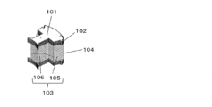
- Patent Document 1 shows a part of a stator used in a conventional electric motor, that is, one of the split stator blocks.
- the stator of this motor is formed into an annular shape by magnetically connecting a plurality of split stator blocks.
- the individual partition stator blocks are formed by sandwiching the second laminate 104 between the first laminate 102.
- the first laminated body 102 is configured by laminating a plurality of stator plates 101 made of electromagnetic steel plates
- the second laminated body 104 is configured by laminating a plurality of stator plates 103 made of amorphous thin plates.
- the first laminated body 102 and the second laminated body 104 are each composed of a plurality of individual stator plates 101 and 103 that are scattered and separated from each other.
- the stator plate 103 made of the amorphous thin plate is formed by separately forming and joining the yoke portion 105 and the teeth portion 106.
- the present disclosure provides an electric motor and a compressor using the same, which simplifies the laminating process of the stator plates constituting the above-mentioned divider block and reduces the manufacturing cost.
- the electric motor in the present disclosure is an electric motor in which a stator is formed by connecting a stator block, and the stator block is a stator formed by continuously connecting a plurality of the stator blocks so as to have a yoke portion and a teeth portion integrally. It has a structure formed by folding and stacking plates.
- the motor according to the present disclosure can reduce the complicated and time-consuming process of matching the shapes of the individual stator plates that are scattered and separated when laminating the stator plates, and can reduce the complicated and time-consuming process, and the yoke portion when forming the stator plates. There is no need for the process of joining the teeth and the teeth. Therefore, the laminating process can be significantly simplified, the manufacturing cost can be reduced, and an inexpensive electric motor and a compressor using the same can be provided.
- FIG. 1 A perspective view showing a stator of an electric motor (motor unit) according to the first embodiment.
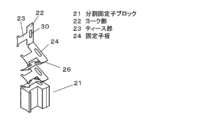
- Enlarged perspective view of the split stator block of the motor unit Perspective view of the stator plate constituting the split stator block of the motor unit
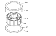
- Perspective view showing the state before mounting the motor unit on the compressor An exploded perspective view of FIG.
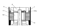
- Sectional drawing which shows the fixed structure of the electric motor part with respect to the closed container in Embodiment 2.
- Perspective view of the split stator block that constitutes the stator of a conventional motor An exploded perspective view showing a yoke portion and a teeth portion of a split stator block constituting a stator of a conventional motor.
- both the first laminated body 102 and the second laminated body 104 constituting the split stator block are formed by individually separating the stator plates constituting the first laminated body 102 and the second laminated body 104. Therefore, when the stator plates 101 and 103 are laminated to form the first laminated body 102 or the second laminated body 104, the shapes of the scattered and separated stator plates 101 and 103 are aligned and laminated. A complicated process is required. Specifically, the amorphous thin plate constituting the second laminated body 104 is extremely thin as compared with the electrical steel sheet.
- stator plate 103 constituting the second laminated body 104 uses an amorphous thin plate having a small iron loss, high efficiency can be achieved.
- the manufacturing cost increases more and more because the process of separately forming and joining the yoke portion 105 and the teeth portion 106 is also required.
- the present disclosure provides an inexpensive electric motor and a compressor using the same, which simplifies the laminating process of the stator plates constituting the split stator block and reduces the manufacturing cost.
- a rotary compressor using an electric motor will be described as an example.
- the motor of the present invention and the compressor using the same are the motors and the rotary compressor described in the following embodiments. It is not limited to the configuration, and includes the configuration of the motor and the compressor equivalent to the technical idea described in the following embodiments.
- FIG. 1 is a vertical cross-sectional view of a compressor using an electric motor according to the embodiment of the present disclosure.
- the compressor of the present embodiment is configured by providing an electric motor unit (motor) 2 and a compression mechanism unit 3 in a closed container 1.
- the closed container 1 is composed of a cylindrical housing 5, an upper cover 6 for closing the opening of the housing 5, and a lower cover 7.
- the compression mechanism portion 3 is arranged at the lower part of the housing 5. Further, the motor unit 2 is arranged on the compression mechanism unit 3 inside the housing 5, and is connected to the compression mechanism unit 3 by the drive shaft 4.
- the upper cover 6 is provided with a terminal 8 for supplying electric power to the motor unit 2.
- An oil sump 9 for holding the lubricating oil is formed at the bottom of the closed container 1.
- the motor unit 2 is composed of a stator 10 and a rotor 11.
- the rotor 11 is fixed to the drive shaft 4 and rotates together with the drive shaft 4. Both ends of the drive shaft 4 are rotatably supported by the upper bearing member 12 and the lower bearing member 13.
- the compression mechanism portion 3 is composed of an upper bearing member 12, a lower bearing member 13, a cylinder 15, a rolling piston 16, and a vane (not shown).
- a discharge pipe 17 is provided on the upper part of the closed container 1.
- the discharge pipe 17 penetrates the upper part of the upper cover 6 and opens toward the internal space of the closed container 1 to guide the refrigerant gas compressed by the compression mechanism 3 to the outside of the closed container 1. It plays a role as a flow path.
- the internal space of the closed container 1 is filled with the compressed refrigerant.
- a suction connecting pipe 19 for supplying a refrigerant to the compression mechanism portion 3 is provided in the lower part of the closed container 1, and an accumulator 18 for gas-liquid separation of the refrigerant gas is connected to the suction connecting pipe 19.
- the accumulator 18 is configured by connecting a refrigerant gas introduction pipe 20 at the upper part and a refrigerant gas outlet pipe connected to the suction connection pipe 19 at the lower part.
- the stator 10 is arranged on the outer circumference of the rotor 11, and the stator 10 is configured by arranging the respective divider blocks 21 in a circular shape as shown in FIG.
- both side portions 21a in the circumferential direction of each partition stator block 21 are connected in an annular shape to form a circular shape.
- each of the above-mentioned split stator blocks 21 is composed of a yoke portion 22 that is in contact with another split stator block 21 in a circular shape to form an outer peripheral circular portion, and a teeth portion 23 that protrudes radially from the yoke portion 22. ing.
- each of the split stator blocks 21 is connected by welding both side portions 21a of the yoke portion 22 on the outer circumference of the stator in the circumferential direction, or fitting of the convex portion and the concave portion as described in Patent Document 1. It is magnetically connected via a coupling means by.
- the stator plate 24 constituting the individual stator blocks 21 is formed by forming the stator block 21 having a laminated height dimension H (see FIG. 4) from the strip-shaped stator material plate 25. It is press-molded in a continuously connected state.
- the yoke portion 22 and the teeth portion 23 are integrally press-molded in the stator plate portion 24a in the connected state, and as shown in FIG. 7, the stator plate portions 24a adjacent to each other, that is, the connecting portion 26, that is, As shown in FIG. 6, both side portions of the yoke portion 22 are folded back to form the split stator block 21.
- the inner and outer edges of the connecting portion (hereinafter referred to as the folded portion) 26 between the adjacent stator plate portions 24a have a width M narrower than the width L of the yoke portion 22 to facilitate folding.
- an acute-angled recess 27 and an obtuse-angled recess 28 are formed.
- a plurality of concave grooves 29 are formed in order to return the oil separated from the refrigerant by the adjacent obtuse angle recesses 28 to the lower part of the closed container.
- the yoke portion 22 of the stator plate 24 is provided with an elongated hole 30 in the folding direction of the stator plate to serve as a guide pin (not shown) insertion hole during the folding stroke.
- the stator material plate 25 which is the material of the stator plate 24, has a thickness of 0.1 mm or less.
- it is a sheet-like thin plate made of an amorphous alloy material having a thickness of several tens of microns or a nanocrystalline soft magnetic material having further improved characteristics of the amorphous alloy.
- the nanocrystalline soft magnetic material is subjected to appropriate heat treatment on a non-uniform amorphous alloy containing ⁇ -Fe nuclei obtained by rapidly solidifying a molten Fe—Si—BP—Cu alloy.
- crystal control at the 10 nanoscale (1 / 100,000 mm) level is performed to improve the soft magnetic properties.
- the stator plate 24 is made of a thin plate made of an amorphous alloy material or a nanocrystal soft magnetic material having a thickness of 0.1 mm or less and a thinner thickness of about several tens of microns in the present embodiment.
- the stator 10 may be formed of electromagnetic steel plates having the same shape as the stator plate 24 on both the upper and lower surfaces of the stator blocks 21 at both ends in the stacking direction in the stacking direction in the state shown in FIG.
- the functional reinforcing plates 31 are laminated to reinforce and protect the surface of the stator 10, and the winding 33 is wound around the insulating material 32 (see FIG. 2).
- the winding 33 of the stator 10 is connected to an inverter circuit (not shown) outside the compressor via a terminal 8 (see FIG. 1), generates a magnetic field by energization, and rotates at a predetermined rotation speed. To drive.
- the motor unit 2 is provided with annular members 34a and 34b for sandwiching the stator 10 in the reinforcing plate 31 portions on both the upper and lower sides of the stator 10.
- the annular members 34a and 34b are fixed to the inner peripheral surface of the closed container 1 by shrink-fitting. That is, the stator 10 of the motor unit 2 is sandwiched and fixed by the upper and lower annular members 34a and 34b which are shrink-fitted and fixed to the closed container 1 without being shrink-fitted or welded to the closed container 1.
- the stator 10 is placed in the closed container 1 by shrinking the stator 10 into the closed container 1 while lightly pressing the stator 10 with the annular members 34a and 34b from above and below.
- the reinforcing plate 31 may be shrink-fitted to be fixed.
- the stator 10 of the motor unit 2 has an outer diameter of the stator plate 24 smaller than the outer diameter of the annular members 34a and 34b that sandwich and fix the stator 10. Further, in this embodiment, the linear expansion coefficient of the annular members 34a and 34b is smaller than the linear expansion coefficient of the closed container 1.
- the annular members 34a and 34b have a pin shaft 36 formed on one of the annular members 34a.
- the pin shaft 36 is a detent portion that fits into the concave groove 29 on the outer circumference of the stator 10 to prevent the rotor 11 from rotating.
- the other annular member 34b is provided with a hole 37 into which the pin shaft 36 is fitted.
- the fixing of the annular members 34a and 34b to the closed container 1 is not limited to shrink-fitting, and may be welded by a laser or the like, or may be lightly shrink-fitted and then welded. is there.
- a stator plate 24 of each of the stator blocks 21 constituting the stator 10 is formed by press molding in a state where a plurality of stator plates 24 are connected, and this is formed by a folding portion 26. It is constructed by stacking while folding back. As a result, the stator plates 24 are automatically laminated in the same shape. Therefore, it is possible to reduce the complicated and time-consuming process of laminating and adhering the individual stator plates 24 that are scattered and separated when laminating the stator plates 24. That is, it is possible to eliminate the complicated and time-consuming process of laminating and adhering the stator plates while aligning their shapes as in the conventional one in which the stator plates are individually separated and scattered, and the stator plate laminating process can be simplified.
- the stator plate 24 is provided with the elongated hole 30 in the folding direction of the stator plate, the elongated hole 30 can be fitted to the guide pin (not shown) during the folding stroke. it can. Therefore, it is possible to reliably suppress a slight displacement of the stacking position of each stator plate 24, which is a concern at the time of folding back, and it is possible to improve the stacking accuracy.
- stator plate 24 is press-molded into a shape having the yoke portion 22 and the teeth portion 23 integrally, the process of joining the yoke portion 22 and the teeth portion 23 as in the conventional stator plate is also reduced. This makes it possible to further simplify the stator plate laminating process.
- stator plate 24 having the yoke portion 22 and the teeth portion 23 integrally has the characteristics of an amorphous alloy material or an amorphous alloy having an extremely thin plate thickness of about several tens of microns and a small iron loss. Since a thin plate made of an improved nanocrystalline soft magnetic material is used, the efficiency of the motor can be improved.
- stator plate 24 having a complicated shape composed of a yoke portion 22 and a teeth portion 23 with a thin plate made of the above-mentioned amorphous alloy material or nanocrystal soft magnetic material, the applicant has made this possible and the yoke.
- the stator plate 24 having the portion 22 and the teeth portion 23 is press-molded.
- reinforcing plates 31 are laminated and arranged on both end faces of the stator block 21 formed by laminating the stator plate 24 made of the above amorphous alloy material or nanocrystal soft magnetic material to reinforce the surface of the stator 10. It protects and winds the winding 33 through the insulating material 32. Therefore, it is possible to prevent deformation and cracking of the stator plate 24 made of an amorphous alloy material or a nanocrystal soft magnetic material which is fragile and thin as about several tens of microns.
- the motor unit 2 arranges annular members 34a and 34b at both ends of the stator 10 formed by connecting the split stator blocks 21 and sandwiches and fixes the annular members 34a and 34b, and the annular members 34a and 34b are closed containers of the compressor. Since the stator 10 is welded or shrink-fitted to 1, the stator 10 is not subjected to the strong compressive stress as when the stator 10 is directly fixed to the closed container 1 by welding or shrink-fitting.
- stator plate 24 of the stator 10 of the motor 2 is made of a fragile amorphous alloy material or a nanocrystal soft magnetic material and the thickness is a sheet-like thin plate having a thickness of about several tens of microns, the stator plate 24 Can be prevented from being distorted and causing a decrease in efficiency of the motor 2. Further, it is not necessary to adjust the laser irradiation time and the amount of heat by welding, and it is possible to prevent the efficiency from being lowered due to the variation in these adjustments.
- the outer diameter of the stator 10 is smaller than the outer diameter of the annular members 34a and 34b that sandwich and fix the stator 10. Therefore, the annular members 34a and 34b receive the compressive stress in the radial direction caused by the heat shrinkage of the closed container 1, and the compressive stress applied to the stator 10 of the motor unit 2 can be suppressed or eliminated.
- stator material plate 25 made of the above-mentioned amorphous alloy material or nanocrystalline soft magnetic material is expensive, but as is clear from FIG. 7, the teeth portions 23 are press-molded so as to face each other to form a strip shape.
- the stator plate 24 can be removed from the stator material plate 25 without waste.
- the stator 10 is continuous in one annular shape without being composed of the split stator block 21, the stator plate 24 constituting the stator 10 becomes an annular shape (ring shape) and is a material of the central portion of the ring. Is discarded, which causes a great waste in material removal.
- stator 10 is a connecting body of the dividing stator blocks 21, the stator plate 24 constituting the stator 10 is press-molded by arranging the teeth portions 23 of the stator plate 24 so as to face each other as described above. As a result, waste of material removal can be almost eliminated, and an increase in the manufacturing cost of the stator 10 can be greatly suppressed.
- the pin shaft 36 provided in one of the annular members 34a of the compressor is fitted into the concave groove 29 on the outer circumference of the stator 10. Therefore, even if the stator 10 of the motor unit 2 is not fixed by shrink fitting or welding, the rotation of the stator 10 can be prevented, and the decrease in efficiency can be suppressed to obtain a high-performance compressor. it can.
- the motor disclosed in the present embodiment includes a rotor 11 and a stator 10 for rotating the rotor 11, and the stator 10 is configured by connecting a plurality of divider blocks 21. Further, the partition stator block 21 is formed by folding and laminating a plurality of stator plates 24 which are continuously connected and formed so as to have the yoke portion 22 and the teeth portion 23 integrally.
- stator plates 24 when laminating the stator plates 24, it is possible to reduce the complicated and time-consuming process of matching the shapes of the individual stator plates 24 that are scattered and separated, and laminating and adhering them, and also to form the stator plates 24. At this time, the step of joining the yoke portion 22 and the teeth portion 23 is also unnecessary. Therefore, the laminating process can be greatly simplified, the manufacturing cost can be reduced, and an inexpensive electric motor and a compressor using the same can be obtained.
- stator plate 24 or all of the stator plate 24 constituting the split stator block 21 is formed of a thin plate of an amorphous alloy material or a nanocrystal material, and the manufacturing cost is high. It is possible to use an inexpensive and high-performance electric motor and a compressor using it while trying to reduce the amount of
- the stator plate 24 has a configuration in which elongated holes 30 are provided at appropriate positions of the individual stator plates 24 in the direction in which the stator plates are folded back. Therefore, it is possible to suppress the stacking deviation of the stator plate by a simple method.
- FIG. 11 is a vertical cross-sectional view showing the electric motor portion of the compressor according to the second embodiment.
- the compressor of the present embodiment has a configuration in which at least one of the annular members 34a and 34b is substituted by a step portion integrally formed on the inner peripheral surface of the closed container 1.
- annular step portion 1a is integrally formed at the lower part of the closed container 1, a lower end portion of the stator 10 of the motor portion 2 is placed on the step portion 1a, and an annular member 34a is further placed on the upper end side of the stator 10. Is inserted and the stator 10 is lightly pressed against the step portion 1a, and the stator 10 is shrink-fitted and fixed in the closed container 1.
- stator 10 of the motor unit 2 is sandwiched and fixed by the step portion 1a provided on the inner peripheral surface of the closed container and the annular member 34a fixed to the inner peripheral surface. Therefore, one of the annular members fixed to the closed container 1 can be abolished, and the productivity can be further improved and the manufacturing cost can be further reduced.
- FIG. 12 is a plan view of the stator material plate forming the stator of the compressor according to the third embodiment
- FIG. 13 is formed by laminating the stator plates press-molded from the stator material plate according to the third embodiment.
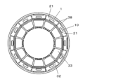
- a perspective view of the stator, FIG. 14, is a plan view showing a state in which the stator according to the third embodiment is shrink-fitted and fixed in a closed container of a compressor.
- stator 10 is directly shrink-fitted and fixed in the closed container 1 without using the annular members 34a and 34b.
- microprojections 38 projecting outward from the outermost peripheral edge of the yoke portion 22 are formed, and the stator plate 24 is formed.
- the micro-projections 38 protruding from the outer peripheral surface of the split stator block 21 shown in FIG. 13 when laminated are formed by shrink-fitting and fixing to the closed container 1.
- the microprojections 38 may be formed not in all the dividing stator blocks 21 but in some dividing stator blocks 21.
- the compressor of the present embodiment configured as described above does not need to use the annular members 34a and 34b described in the first embodiment. Further, since the strength of the microprojections 38 provided in the folded-back portion 26 is improved by work hardening, deformation and the like are suppressed even when the compression pressure from the closed container 1 is applied. Moreover, since the microprojections 38 are located on a part of both side portions of the yoke portion 22, even if there is some deformation or the like, the influence on the magnetic characteristics of the entire yoke portion is small. Therefore, the deterioration of the magnetic characteristics due to the compression pressure from the closed container 1 is small, and the simplification of the configuration can be promoted while suppressing the decrease in the efficiency of the motor.
- Embodiments 1, 2 and 3 have been described as examples of the techniques disclosed in this application. However, the technique in the present disclosure is not limited to this, and can be applied to embodiments in which changes, replacements, additions, omissions, etc. have been made.
- the electric motor has been described as an inner rotor type motor, but it may be an outer rotor type motor.
- stator plate 24 of the divider block 21 constituting the stator 10 is made of an amorphous alloy material or a nano-crystal soft magnetic material, but this may be a stator plate formed of an electromagnetic steel plate or the like. Often, a stator plate made of an electromagnetic steel plate or the like can be folded back and laminated to simplify the laminating process.
- a stator plate 24 made of an electromagnetic steel plate is folded and laminated on both end faces of a stator plate made of an amorphous alloy material or a nano-crystalline soft magnetic material, that is, an amorphous alloy material or a nano.
- a stator plate 24 made of an electromagnetic steel plate is folded and laminated on both end faces of a stator plate made of an amorphous alloy material or a nano-crystalline soft magnetic material, that is, an amorphous alloy material or a nano.
- the combination of 24 layers of a stator plate made of a crystalline soft magnetic material and a stator plate 24 made of an electromagnetic steel plate has been described.
- the stator 10 may be formed only by the stator plate 24 made of an amorphous alloy material or a nanocrystalline soft magnetic material.
- stator plate 24 made of electromagnetic steel plate When the stator plate 24 made of electromagnetic steel plate is used in combination, the stator plate 24 made of electromagnetic steel plate may be laminated in the middle of laminating the stator plate 24 made of an amorphous alloy material or a nanocrystalline soft magnetic material. It's a good one.
- the compressor has been described as having a rotary type compression mechanism, it may be a compressor of a scroll type, a reciprocating type, a screw type, etc., and can be applied to a compressor of various compression types.
- the present invention can greatly simplify the laminating process of the split stator blocks constituting the stator, it is possible to reduce the manufacturing cost, and to reduce the manufacturing cost, an inexpensive electric motor and a compressor using the same. Can be provided. Therefore, it can be used as a compressor for a refrigerating system of various devices such as an air conditioner, a refrigerator, a blower, and a water heater, and as an electric motor for driving the compressor.
Landscapes
- Engineering & Computer Science (AREA)
- Mechanical Engineering (AREA)
- General Engineering & Computer Science (AREA)
- Power Engineering (AREA)
- Manufacturing & Machinery (AREA)
- Iron Core Of Rotating Electric Machines (AREA)
- Manufacture Of Motors, Generators (AREA)
- Applications Or Details Of Rotary Compressors (AREA)
- Structures Of Non-Positive Displacement Pumps (AREA)
Priority Applications (2)
| Application Number | Priority Date | Filing Date | Title |
|---|---|---|---|
| CN202080083207.3A CN114731073B (zh) | 2019-12-04 | 2020-09-23 | 电动机和使用它的压缩机 |
| JP2021562466A JP7486082B2 (ja) | 2019-12-04 | 2020-09-23 | 電動機及びそれを用いた圧縮機 |
Applications Claiming Priority (2)
| Application Number | Priority Date | Filing Date | Title |
|---|---|---|---|
| JP2019219215 | 2019-12-04 | ||
| JP2019-219215 | 2019-12-04 |
Publications (1)
| Publication Number | Publication Date |
|---|---|
| WO2021111708A1 true WO2021111708A1 (ja) | 2021-06-10 |
Family
ID=76220999
Family Applications (1)
| Application Number | Title | Priority Date | Filing Date |
|---|---|---|---|
| PCT/JP2020/035765 Ceased WO2021111708A1 (ja) | 2019-12-04 | 2020-09-23 | 電動機及びそれを用いた圧縮機 |
Country Status (3)
| Country | Link |
|---|---|
| JP (1) | JP7486082B2 (https=) |
| CN (1) | CN114731073B (https=) |
| WO (1) | WO2021111708A1 (https=) |
Citations (5)
| Publication number | Priority date | Publication date | Assignee | Title |
|---|---|---|---|---|
| JPS62129276U (https=) * | 1986-02-05 | 1987-08-15 | ||
| JPH0819196A (ja) * | 1993-11-08 | 1996-01-19 | Mitsubishi Electric Corp | 回転電動機並びにその製造方法並びに積層コア並びにその製造方法 |
| JP2014155347A (ja) * | 2013-02-08 | 2014-08-25 | Mitsubishi Electric Corp | 分割鉄心、及びこの分割鉄心を用いた固定子、並びにこの固定子を備えた回転電機 |
| JP2015053806A (ja) * | 2013-09-06 | 2015-03-19 | 株式会社デンソー | 回転電機の固定子鉄心の製造方法 |
| JP2017005980A (ja) * | 2015-05-27 | 2017-01-05 | ジョンソン エレクトリック ソシエテ アノニム | 電気モータのための磁気コア |
Family Cites Families (3)
| Publication number | Priority date | Publication date | Assignee | Title |
|---|---|---|---|---|
| JP3730218B2 (ja) * | 2000-08-29 | 2005-12-21 | 三菱電機株式会社 | 積重ステータコアとその製造方法および回転電動機とその製造方法 |
| JP4856999B2 (ja) * | 2006-03-24 | 2012-01-18 | 日立アプライアンス株式会社 | モータ |
| WO2015056364A1 (ja) * | 2013-10-15 | 2015-04-23 | パナソニックIpマネジメント株式会社 | 圧縮機 |
-
2020
- 2020-09-23 JP JP2021562466A patent/JP7486082B2/ja active Active
- 2020-09-23 WO PCT/JP2020/035765 patent/WO2021111708A1/ja not_active Ceased
- 2020-09-23 CN CN202080083207.3A patent/CN114731073B/zh active Active
Patent Citations (5)
| Publication number | Priority date | Publication date | Assignee | Title |
|---|---|---|---|---|
| JPS62129276U (https=) * | 1986-02-05 | 1987-08-15 | ||
| JPH0819196A (ja) * | 1993-11-08 | 1996-01-19 | Mitsubishi Electric Corp | 回転電動機並びにその製造方法並びに積層コア並びにその製造方法 |
| JP2014155347A (ja) * | 2013-02-08 | 2014-08-25 | Mitsubishi Electric Corp | 分割鉄心、及びこの分割鉄心を用いた固定子、並びにこの固定子を備えた回転電機 |
| JP2015053806A (ja) * | 2013-09-06 | 2015-03-19 | 株式会社デンソー | 回転電機の固定子鉄心の製造方法 |
| JP2017005980A (ja) * | 2015-05-27 | 2017-01-05 | ジョンソン エレクトリック ソシエテ アノニム | 電気モータのための磁気コア |
Also Published As
| Publication number | Publication date |
|---|---|
| JP7486082B2 (ja) | 2024-05-17 |
| CN114731073A (zh) | 2022-07-08 |
| CN114731073B (zh) | 2025-12-05 |
| JPWO2021111708A1 (https=) | 2021-06-10 |
Similar Documents
| Publication | Publication Date | Title |
|---|---|---|
| AU2008336853B2 (en) | Armature core, armature, rotary electric machine and compressor | |
| CN110603716B (zh) | 转子、电动机、压缩机及空调装置 | |
| CN101796707B (zh) | 轴向间隙型旋转电机和旋转驱动装置 | |
| CN108028557B (zh) | 永磁铁嵌入式电动机、压缩机以及制冷空调装置 | |
| CN101461119B (zh) | 分割型定子铁心及其制造方法、定子铁心 | |
| JP5478461B2 (ja) | 電動機及び圧縮機 | |
| WO2018138864A1 (ja) | 固定子、電動機、圧縮機、および冷凍空調装置 | |
| CN102195381A (zh) | 电动机、电动机的制造方法、压缩机 | |
| WO2007114079A1 (ja) | 電機子コア、それを用いたモータおよびその製造方法 | |
| JP2008228363A (ja) | 電機子用磁芯、電機子、回転電機、圧縮機 | |
| JP2004096978A (ja) | 永久磁石埋め込み型電動機及び回転式圧縮機 | |
| JP2005151648A (ja) | モータ及びモータの製造方法並びに駆動装置、圧縮機、移動体 | |
| WO2018138866A1 (ja) | 固定子、電動機、圧縮機、および冷凍空調装置 | |
| KR100675549B1 (ko) | 전동 콤프레서 | |
| CN112601890B (zh) | 压缩机 | |
| JP7012264B2 (ja) | 圧縮機 | |
| WO2021111708A1 (ja) | 電動機及びそれを用いた圧縮機 | |
| JP5003425B2 (ja) | 回転子及びその製造方法、回転電機、圧縮機 | |
| JP3615014B2 (ja) | 磁石回転子及びその製造方法 | |
| WO2019064403A1 (ja) | 回転子、電動機、密閉型圧縮機および回転子の製造方法 | |
| JP7150175B2 (ja) | 固定子鉄心、固定子、電動機、及び、圧縮機 | |
| JP5365109B2 (ja) | ティース、電機子用磁芯 | |
| JPWO2020208777A1 (ja) | 圧縮機、及び、圧縮機用電動機 | |
| CN216356120U (zh) | 定子、电机、压缩机和电器设备 | |
| JP2009136134A (ja) | 電機子用磁芯及びその製造方法、電機子、回転電機、圧縮機 |
Legal Events
| Date | Code | Title | Description |
|---|---|---|---|
| 121 | Ep: the epo has been informed by wipo that ep was designated in this application |
Ref document number: 20895806 Country of ref document: EP Kind code of ref document: A1 |
|
| ENP | Entry into the national phase |
Ref document number: 2021562466 Country of ref document: JP Kind code of ref document: A |
|
| NENP | Non-entry into the national phase |
Ref country code: DE |
|
| 122 | Ep: pct application non-entry in european phase |
Ref document number: 20895806 Country of ref document: EP Kind code of ref document: A1 |