WO2021111589A1 - 光コネクタおよび光接続構造 - Google Patents
光コネクタおよび光接続構造 Download PDFInfo
- Publication number
- WO2021111589A1 WO2021111589A1 PCT/JP2019/047636 JP2019047636W WO2021111589A1 WO 2021111589 A1 WO2021111589 A1 WO 2021111589A1 JP 2019047636 W JP2019047636 W JP 2019047636W WO 2021111589 A1 WO2021111589 A1 WO 2021111589A1
- Authority
- WO
- WIPO (PCT)
- Prior art keywords
- optical
- optical fiber
- optical connector
- magnet
- component
- Prior art date
Links
Images


Classifications
-
- G—PHYSICS
- G02—OPTICS
- G02B—OPTICAL ELEMENTS, SYSTEMS OR APPARATUS
- G02B6/00—Light guides; Structural details of arrangements comprising light guides and other optical elements, e.g. couplings
- G02B6/24—Coupling light guides
- G02B6/36—Mechanical coupling means
- G02B6/38—Mechanical coupling means having fibre to fibre mating means
- G02B6/3807—Dismountable connectors, i.e. comprising plugs
- G02B6/389—Dismountable connectors, i.e. comprising plugs characterised by the method of fastening connecting plugs and sockets, e.g. screw- or nut-lock, snap-in, bayonet type
-
- G—PHYSICS
- G02—OPTICS
- G02B—OPTICAL ELEMENTS, SYSTEMS OR APPARATUS
- G02B6/00—Light guides; Structural details of arrangements comprising light guides and other optical elements, e.g. couplings
- G02B6/24—Coupling light guides
- G02B6/36—Mechanical coupling means
- G02B6/38—Mechanical coupling means having fibre to fibre mating means
- G02B6/3807—Dismountable connectors, i.e. comprising plugs
- G02B6/3873—Connectors using guide surfaces for aligning ferrule ends, e.g. tubes, sleeves, V-grooves, rods, pins, balls
- G02B6/3886—Magnetic means to align ferrule ends
-
- G—PHYSICS
- G02—OPTICS
- G02B—OPTICAL ELEMENTS, SYSTEMS OR APPARATUS
- G02B6/00—Light guides; Structural details of arrangements comprising light guides and other optical elements, e.g. couplings
- G02B6/24—Coupling light guides
- G02B6/36—Mechanical coupling means
- G02B6/38—Mechanical coupling means having fibre to fibre mating means
- G02B6/3807—Dismountable connectors, i.e. comprising plugs
- G02B6/3873—Connectors using guide surfaces for aligning ferrule ends, e.g. tubes, sleeves, V-grooves, rods, pins, balls
- G02B6/3885—Multicore or multichannel optical connectors, i.e. one single ferrule containing more than one fibre, e.g. ribbon type
-
- G—PHYSICS
- G02—OPTICS
- G02B—OPTICAL ELEMENTS, SYSTEMS OR APPARATUS
- G02B6/00—Light guides; Structural details of arrangements comprising light guides and other optical elements, e.g. couplings
- G02B6/24—Coupling light guides
- G02B6/42—Coupling light guides with opto-electronic elements
- G02B6/4201—Packages, e.g. shape, construction, internal or external details
- G02B6/4219—Mechanical fixtures for holding or positioning the elements relative to each other in the couplings; Alignment methods for the elements, e.g. measuring or observing methods especially used therefor
- G02B6/4228—Passive alignment, i.e. without a detection of the degree of coupling or the position of the elements
- G02B6/423—Passive alignment, i.e. without a detection of the degree of coupling or the position of the elements using guiding surfaces for the alignment
- G02B6/4231—Passive alignment, i.e. without a detection of the degree of coupling or the position of the elements using guiding surfaces for the alignment with intermediate elements, e.g. rods and balls, between the elements
-
- G—PHYSICS
- G02—OPTICS
- G02B—OPTICAL ELEMENTS, SYSTEMS OR APPARATUS
- G02B6/00—Light guides; Structural details of arrangements comprising light guides and other optical elements, e.g. couplings
- G02B6/24—Coupling light guides
- G02B6/36—Mechanical coupling means
- G02B6/38—Mechanical coupling means having fibre to fibre mating means
- G02B6/3807—Dismountable connectors, i.e. comprising plugs
- G02B6/381—Dismountable connectors, i.e. comprising plugs of the ferrule type, e.g. fibre ends embedded in ferrules, connecting a pair of fibres
- G02B6/3818—Dismountable connectors, i.e. comprising plugs of the ferrule type, e.g. fibre ends embedded in ferrules, connecting a pair of fibres of a low-reflection-loss type
-
- G—PHYSICS
- G02—OPTICS
- G02B—OPTICAL ELEMENTS, SYSTEMS OR APPARATUS
- G02B6/00—Light guides; Structural details of arrangements comprising light guides and other optical elements, e.g. couplings
- G02B6/24—Coupling light guides
- G02B6/36—Mechanical coupling means
- G02B6/38—Mechanical coupling means having fibre to fibre mating means
- G02B6/3807—Dismountable connectors, i.e. comprising plugs
- G02B6/381—Dismountable connectors, i.e. comprising plugs of the ferrule type, e.g. fibre ends embedded in ferrules, connecting a pair of fibres
- G02B6/3825—Dismountable connectors, i.e. comprising plugs of the ferrule type, e.g. fibre ends embedded in ferrules, connecting a pair of fibres with an intermediate part, e.g. adapter, receptacle, linking two plugs
-
- G—PHYSICS
- G02—OPTICS
- G02B—OPTICAL ELEMENTS, SYSTEMS OR APPARATUS
- G02B6/00—Light guides; Structural details of arrangements comprising light guides and other optical elements, e.g. couplings
- G02B6/24—Coupling light guides
- G02B6/36—Mechanical coupling means
- G02B6/38—Mechanical coupling means having fibre to fibre mating means
- G02B6/3807—Dismountable connectors, i.e. comprising plugs
- G02B6/389—Dismountable connectors, i.e. comprising plugs characterised by the method of fastening connecting plugs and sockets, e.g. screw- or nut-lock, snap-in, bayonet type
- G02B6/3891—Bayonet type
-
- G—PHYSICS
- G02—OPTICS
- G02B—OPTICAL ELEMENTS, SYSTEMS OR APPARATUS
- G02B6/00—Light guides; Structural details of arrangements comprising light guides and other optical elements, e.g. couplings
- G02B6/24—Coupling light guides
- G02B6/36—Mechanical coupling means
- G02B6/40—Mechanical coupling means having fibre bundle mating means
- G02B6/403—Mechanical coupling means having fibre bundle mating means of the ferrule type, connecting a pair of ferrules
Definitions
- the present invention relates to an optical fiber connection component, and more particularly to an optical connector and an optical connection structure which are miniaturized by holding and pressing fibers with each other by a magnet.
- the pluggable transceiver various optical components such as an optical transceiver, an electric circuit component for controlling them, a printed circuit board, and the like are housed in the metal housing.
- the housing is provided with a guide structure that allows the optical connector to be inserted and removed from the outside, and by inserting an optical connector that matches the guide structure, it is optically coupled to the optical transmitter / receiver inside the housing. It is possible to do.
- the size of the pluggable transceiver has been reduced year by year in response to the need for an increase in communication capacity, and the housing has been reduced to the same extent as the guide structure for the optical connector. Therefore, in order to further reduce the size of the housing in the future, it is required to reduce the size of the guide mechanism, that is, to further reduce the size of the optical connector that fits the guide mechanism. Further, there is also an application of connecting optical fibers to each other in the small housing, and an optical connector as small as possible is required in this application as well.
- optical connectors for connecting optical fibers are known as SC connectors and LC connectors
- SC connectors and LC connectors are known as SC connectors and LC connectors
- single-core connectors using cylindrical ferrules are known.
- MT connector and MPO connector based on the MT connector are known.
- the multi-core connector is used as an interface of a pluggable transceiver like the single-core connector, and is widely used especially for multi-channel parallel transmission applications.
- positioning is performed by accommodating and aligning fibers in a cylindrical ferrule component and connecting them facing each other via a split sleeve. That is, independent parts are used for the optical fiber alignment part (single-core ferrule) and the high-precision alignment part (split sleeve) between the ferrules.
- the multi-core connector a plurality of fibers are adhered and fixed to a resin-molded ferrule having a plurality of holes for accommodating the fibers and two guide holes for accommodating / inserting the guide pin, and one ferrule is used.
- the fibers are connected to each other by fitting the guide pins provided in the above to the other ferrule.
- high-precision positioning between the fibers is realized by the high hole diameter accuracy of each of the fiber accommodating hole and the guide pin hole and the high hole positioning accuracy. That is, in the multi-core connector, the high-precision alignment structure (guide pin) between the ferrules is integrated with the optical fiber alignment component (multi-core ferrule) itself.
- connection end face of the fiber and the ferrule is polished.
- the MT connector of the multi-core connector has a right-angled end face
- the MPO connector has an oblique end face.
- the end face of the fiber is often polished so that it slightly protrudes from the end face of the ferrule.
- the ferrules are pressed against each other by a clip, and the matching oil whose refractive index is matched to the connection end face. Is dropped.
- physical contact (PC) connection which is a close connection between cores, is realized by pressing diagonally end faces with each other and pressing them against each other by a coil spring provided behind each other's ferrules. This prevents the Fresnel reflection.
- the multi-core optical connector having the above structure uses a spring component such as a clip or a coil spring and a mechanical fastening structure for constantly applying the pressing force of this spring component to the connection end face, there is a limit to miniaturization. ..
- a spring component such as a clip or a coil spring
- a mechanical fastening structure for constantly applying the pressing force of this spring component to the connection end face
- the present invention has been made to solve the above problems, and to provide a multi-core compact optical connector capable of realizing a PC connection without using mechanical fastening parts or spring parts. The purpose.
- the optical connector according to the present invention is an optical connector for connecting optical fibers having a waveguide having a waveguide surrounded by a clad so as to face each other, and the optical connector is described above.
- the fiber, the optical fiber alignment component having a hole for accommodating the optical fiber, and the optical fiber alignment component are arranged around a part of at least one side surface in the outer peripheral direction or near a part of the end surface on the connecting side.
- the optical fiber alignment component is provided with a fitting structure for aligning optical fibers with each other, including at least one pair of connecting components including a magnet or a metallic magnetic material, and at least one of the connecting components including a magnet. It is characterized in that an attractive force acts between the connecting parts.
- a physical contact connection can be realized, and a smaller optical connector can be realized.
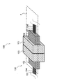
- FIG. 1A is a perspective view of the optical connector according to the first embodiment of the present invention before connection.
- FIG. 1B is a perspective view of the optical connector according to the first embodiment of the present invention after connection.
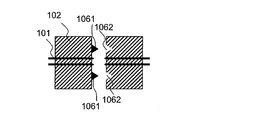
- FIG. 2A is a top sectional view of the optical connector according to the first embodiment of the present invention before connection.
- FIG. 2B is a top sectional view of the optical connector according to the first embodiment of the present invention after connection.
- FIG. 3A is a top sectional view of the fitting structure of the optical connector according to the first embodiment of the present invention.
- FIG. 3B is a top sectional view of the fitting structure of the optical connector according to the first embodiment of the present invention.
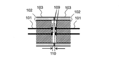
- FIG. 4A is a top sectional view of an optical fiber connection portion of the optical connector according to the first embodiment of the present invention.
- FIG. 4B is a top sectional view of the optical fiber connection portion of the optical connector according to the first embodiment of the present invention.
- FIG. 5A is a top sectional view before connecting the optical connector according to the modified example of the first embodiment of the present invention.
- FIG. 5B is a top sectional view of the optical connector according to the modified example of the first embodiment of the present invention after connection.
- FIG. 6A is a top sectional view of the optical connector according to the second embodiment of the present invention.
- FIG. 6B is a side sectional view of the optical connector according to the second embodiment of the present invention.
- FIG. 7A is a top sectional view of the optical connector according to the third embodiment of the present invention before connection.
- FIG. 7B is a top sectional view of the optical connector according to the third embodiment of the present invention after connection.
- FIG. 7C is an enlarged cross-sectional view of the upper surface of the optical fiber joint portion after the connection of the optical connector according to the third embodiment of the present invention.
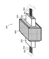
- FIG. 8A is a perspective view of the optical connector according to the fourth embodiment of the present invention.
- FIG. 8B is a top sectional view of the optical connector according to the fourth embodiment of the present invention.
- FIG. 9A is a perspective view of an optical connection structure according to a fifth embodiment of the present invention.
- FIG. 9B is a top sectional view of the optical connection structure according to the fifth embodiment of the present invention.
- FIG. 10A is a perspective view of an optical connection structure according to a sixth embodiment of the present invention.
- FIG. 10B is a top sectional view of the optical connection structure according to the sixth embodiment of the present invention.
- FIG. 11 is a top sectional view of a fitting portion of the optical connection structure according to the sixth embodiment of the present invention.
- FIG. 12 is a top sectional view of an optical connection structure according to a modified example of the sixth embodiment of the present invention.
- FIG. 13 is a top sectional view of an optical connection structure according to a modified example of the sixth embodiment of the present invention.
- FIG. 14A is a top sectional view of the optical connector according to the seventh embodiment of the present invention before connection.
- FIG. 14A is a top sectional view of the optical connector according to the seventh embodiment of the present invention before connection.
- FIG. 14B is a top sectional view of the optical connector according to the seventh embodiment of the present invention after connection.
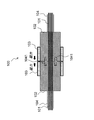
- FIG. 15A is a side sectional view of the optical connection structure according to the eighth embodiment of the present invention before connection.
- FIG. 15B is a side sectional view of the optical connection structure according to the eighth embodiment of the present invention after connection.
- FIG. 16A is a side sectional view of the optical connection structure according to the modified example of the eighth embodiment of the present invention before connection.
- FIG. 16B is a side sectional view of the optical connection structure according to the modified example of the eighth embodiment of the present invention after connection.
- FIGS. 1A and 1B are perspective views before and after connecting the optical connector 100 according to the first embodiment of the present invention.
- the plane A in the figure is a horizontal plane including the central axis of the optical connector 100.
- 2A and 2B are cross-sectional views (hereinafter, referred to as “top cross-sectional view”) with a plane A as a cross section before and after the connection of the optical connector 100.
- top cross-sectional view cross-sectional views
- optical fiber longitudinal direction the direction of the optical fiber housed in the optical connector according to the present invention.
- a cross-sectional view including the central axis of the optical connector according to the present invention in the longitudinal direction of the optical fiber and having a plane perpendicular to the plane A as a cross section is referred to as a “side cross-sectional view”.
- the optical connector 100 includes an optical fiber 101 and an optical fiber alignment component 102, and the optical fibers 101 are aligned with each other by a fitting structure provided in the optical fiber alignment component 102 so as to face each other. It is a structure in which the connection is made.
- the optical fiber alignment component 102 is provided with at least a plurality of microholes having an inner diameter slightly larger than the outer diameter of the optical fiber 101 in the optical fiber alignment component 102, and the optical fiber 101 having the coating removed in the microholes. Is housed, and the optical fiber 101 and the optical fiber aligning component 102 are fixed by an adhesive. Note that the adhesive is not shown in the drawings.
- optical fibers 101 are attached to the optical fiber tape 104.
- connection end faces 105 of the optical fiber 101 and the optical fiber alignment component 102 are substantially the same surface (plane polishing is performed so as to be the same.
- connection component 103 capable of accommodating the optical fiber alignment component 102 is optical fiber alignment. It is arranged so as to surround the periphery of the component 102 in the outer peripheral direction.
- the outer peripheral direction of the optical fiber aligned component means a direction along the outer periphery of the optical fiber aligned component on a plane perpendicular to the longitudinal direction of the optical fiber.
- the connecting component 103 in the present embodiment is an opening capable of accommodating an optical fiber aligning component 102 (for example, in the case of MT ferrule, the width is about 2 to 10 mm, the height is about 1 to 5 mm, and the length is about 2 to 10 mm).
- the size of the connecting component 103 is about 3 to 15 mm in width, about 2 to 10 mm in height, and about 3 to 10 mm in length.
- the optical fiber alignment component 102 has a fitting structure, and two metal guide pins 1041 used in a known multi-core ferrule are used for guide pins provided in the optical fiber alignment component (ferrule) 102. By inserting it into the hole 1042, the pins are fitted and aligned. While being fitted by these guide pins, the connecting component 103 is further composed of a magnet, and an attractive force acts to attract the connecting end faces to each other.
- the optical fiber may be a quartz fiber or a plastic fiber.
- the MT ferrule is used for the optical fiber alignment component 102
- a known multi-core ferrule can also be used.
- any of general-purpose plastics, engineering plastics, super engineering plastics, etc., which are often used for multi-core ferrules may be used.
- a glass material, a semiconductor material such as silicon, or ceramic may be used with the same structure as the multi-core ferrule.
- the optical fiber is positioned and arranged with high accuracy, the same effect can be obtained.
- the fiber is accommodated in a glass V-groove, and the fiber is accommodated from above.
- a structure in which a lid component is covered and fixed with an adhesive may be used.
- a known tube, nylon coating, or the like may be further provided around the coating in two or more layers.
- a known tape fiber that is taped and bundled may be used.
- the guide pin 1041 and the guide pin hole 1042 are used in the fitting structure in the present embodiment.
- the fitting structure is not limited to the above, and as shown in FIG. 3A, for example, as in the fitting of the notch 1111 and the groove 1112, a protrusion or the like is formed or attached to one ferrule end face, and the other.
- a guide groove or the like that fits the protrusion may be provided on the end face of the ferrule.
- an external fitting guide structure 107 or the like may be used, and can be applied to any other fitting structure as long as the same accuracy can be guaranteed.
- one ferrule has an insertion hole
- the other ferrule has an outer shape that matches the shape of the insertion hole.
- the connecting part 103 is made of a permanent magnet.
- any known magnet may be used depending on the magnetic force to be expressed.
- a neodymium magnet a magnet that is magnetized to N pole and S pole along the longitudinal direction of the optical fiber.
- ferrite magnets, alnico magnets, samarium-cobalt magnets, KS steel, MK steel, neodymium iron boron magnets, and the like can be used.
- the connecting component 103 made of a permanent magnet is magnetized to N pole and S pole along the longitudinal direction of the optical fiber.
- the other connecting component 103 may be a metal magnetic material.
- SUS430 As an inexpensive material excellent in machining, SUS430, iron, nickel, cobalt, or a material having magnetism of stainless steel (SUS), which is an iron-based alloy, can be used.
- the optical fiber alignment component 102 and the connecting component 103 are pre-integrated by any method such as bonding, mechanical fitting, or various joining techniques. Further, in the first embodiment, as shown in FIGS. 1A and 1B, an example is shown in which the outer shapes of the optical fiber aligning parts 102 and the connecting parts 103 are rectangular / rectangular, but of course, any shape can be used for the outer shapes. it can. For example, the outer shape may be circular, elliptical, polygonal, or the like. The above is the same for the following other embodiments.
- the optical fiber 101 is polished so as to slightly protrude from the optical fiber alignment component 102 with respect to the optical fiber longitudinal direction of the connection end face, and the connection end face of the connection component 103 and the optical fiber alignment component 102.
- the connection end faces are positioned and integrated so as to be substantially flush with each other.
- a pressing force is applied by a coil spring or a clip in order to hold the gap between the opposing optical fibers 101 so as to be eliminated, and in the MPO connector or the like, the pressing force of the coil spring is applied.
- It has a housing structure that provides a mechanical fastening structure for always adding to the connection end face.
- PC physical contact
- the connection 108 can be realized.
- a refractive index matching agent may be provided between them as described later in another embodiment.
- the end face of the optical fiber alignment component 102 and the end face of the optical fiber 101 may be polished at a constant angle with respect to the direction orthogonal to the longitudinal direction of the optical fiber.
- the facing surfaces of the connecting component 103 are preferably parallel to each other in order to stabilize the vector of the attractive force by the magnet in the longitudinal direction of the optical fiber.
- the parallelism is not perfect, the decrease in optical coupling loss can be ignored unless the butt angles of the ferrules in the longitudinal direction deviate significantly. That is, good optical characteristics can be achieved even with parallelism that can be ensured with practical machining accuracy.
- connecting component 103 is arranged so as to cover the outer periphery of the optical fiber alignment component 102 in the present embodiment, it is not necessary to completely cover the connecting component 103, and the connecting component 103 is arranged on only one surface or two surfaces of the outer periphery. You may.
- the connecting component 103 is arranged so as to surround a part of four surfaces of the side wall in the outer peripheral direction of the optical fiber aligning component 102, but the present invention is not limited to this. It may be arranged so as to surround the entire outer circumference of the side wall of the fiber alignment component 102. Further, the optical fiber alignment component 102 may be arranged so as to surround only a part of the side wall of the optical fiber alignment component 102 instead of all four surfaces thereof, and at least one of the side surfaces of the optical fiber alignment component 102 in the outer peripheral direction. It may be arranged around the part.
- this optical connector can be arranged in multiple rows due to the nature of a magnet. That is, it is also possible to provide a multi-core optical connector without a gap by arranging the multi-core optical connectors side by side.
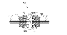
- 5A and 5B are top sectional views before and after connecting the optical connector according to the modified example of the first embodiment of the present invention.
- the connecting component (magnet) 123 is appropriately arranged in the vicinity of the connecting end face 125 of the optical fiber aligning component 122, the size of the magnet and the like can be appropriately set. It is possible to obtain the same effect as that of the embodiment of.
- the connecting component (magnet) 123 may be arranged in a line (surrounding) in the outer peripheral direction of the optical fiber alignment component 122 in the vicinity of the connection end surface 125 of the optical fiber alignment component 122, or the connection end surface 125 may be arranged. It may be arranged in a part of the vicinity of the above, that is, in one or more places.
- the connecting component 123 may have a structure including a magnet as a part thereof.
- FIG. 6A shows a top sectional view of the optical connector 200 according to the second embodiment of the present invention
- FIG. 6B shows a side sectional view thereof.
- FIG. 6A also shows an enlarged view of the peripheral portion B of the optical fiber 201 in the connection end surface 205 of the optical fiber aligning component 202.
- FIG. 6B also shows an enlarged view of the peripheral portion C of the optical fiber 201 in the connection end surface 205 of the optical fiber aligning component 102.
- the configuration of the optical connector 200 according to the present embodiment is the same as that of the first embodiment, but the multi-core ferrule 202 for the MT connector is used as the optical fiber alignment component.
- the optical fiber 201 single mode fibers having a core diameter of about 10 ⁇ m are arranged.
- connection end face when the connection end face is viewed from the side surface, the diagonal end face is polished to about 8 degrees.
- the angle may be an angle other than 8 degrees, and may be 5 degrees or 10 degrees.
- the end face of the optical fiber 201 is slightly projected and polished when viewed from the end face of the ferrule 202, and the tip of the fiber is polished so as to have a convex spherical surface.
- the connecting component 103 uses a neodymium magnet, and its poles are magnetized in the longitudinal direction of the optical fiber and are arranged so as to face each other so as to be a combination that exerts an attractive force with the north pole (S pole) of the connecting component. .. All the fiber cores are brought into close contact with each other by the pressing force of the magnet, and the PC connection is realized as shown in FIG. 4A.
- a compact PC-connected multi-core optical connector can be realized by eliminating the structure.
- FIGS. 6A and 6B are defined by arranging the poles of the magnet in the longitudinal direction of the optical fiber, it is better than using one of them as a metallic magnetic material.
- the attractive force of the magnet can be expressed more, and a smaller optical connector and optical connection structure can be provided.
- ⁇ Third embodiment> 7A and 7B show top sectional views of the optical connector 300 according to the third embodiment of the present invention before and after the connection. Further, FIG. 7C shows an enlarged view of the connection portion of the optical fiber 301.
- the configuration of the optical connector 300 according to the present embodiment is almost the same as that of the second embodiment, but each fiber end face is projected and polished so as to be a right-angled end face when viewed from the side surface. Further, one of the connecting parts is SUS430. Further, a refractive index matching agent 305 is interposed between the connection end faces of the optical fibers 301 to be connected.
- a compact multi-core optical connector can be realized by eliminating the structure.
- the attractive force of the magnet is reduced by using metal on one side, it is possible to connect without specifying a pair of male and female.
- one connecting part contains a metallic magnetic material and the other connecting part contains a magnet
- the attractive force of the magnet is reduced, but the polarity of the magnet of the other connecting part is not determined. It has the effect that the degree of freedom in selecting the polarity is not restricted.
- the refractive index matching agent 305 since the refractive index matching agent 305 is used, Fresnel reflection can be prevented without connecting to a PC, and as a result, sufficient characteristics can be realized even with a small pressing force. It is possible to provide an optical connection structure.
- any known matching agent such as gel, liquid, or film may be used as long as the same effect can be obtained.
- FIG. 8A shows a perspective view of the optical connector 400 according to the fourth embodiment of the present invention
- FIG. 8B shows a top sectional view thereof.
- the configuration of the optical connector 400 according to the present embodiment is substantially the same as that of the first embodiment, but the connecting component 403 has a shape in which two magnets 4031 and 4032 are divided and overlapped.
- the connecting parts on the opposite side are arranged with north and south poles so that an attractive force acts.
- the optical connector 400 has a pair of connecting parts 403A and 403B.
- the connecting part 403A is composed of the divided portions 4031A and 4032A.
- the portion 4031A faces the portion 4032A on two surfaces (upper and lower sides of the optical fiber alignment component 402 in FIG. 8A), and one surface (for example, the upper side of the optical fiber alignment component 402 in FIG. 8A) is N.
- the pole and the other surface are magnetized to the S pole and magnetized in the outer peripheral direction of the optical fiber alignment component 402.
- the portion 4032A faces the portion 4031A on two surfaces (upper side and lower side of the optical fiber alignment component 402 in FIG. 8A), and one surface (for example, the upper side of the optical fiber alignment component 402 in FIG. 8A). Is magnetized to the south pole, and the other surface (for example, the lower side of the optical fiber alignment component 402 in FIG. 8A) is magnetized to the north pole and magnetized in the outer peripheral direction of the optical fiber alignment component 402.
- connecting part 403B has the same configuration as the connecting part 403A, but the north and south poles of the 4031B and 4032B are arranged so as to have opposite polarities to the connecting part 403A.
- 4031B has the opposite polarity to 4032A, which is in contact with the optical fiber in the longitudinal direction.
- 4032A is magnetized on one surface (eg, above the fiber optic alignment component 402 in FIG. 8A) to the north pole and the other surface (eg, below FIG. 8A, below the fiber optic alignment component 402) to the south pole.
- one surface for example, the upper side of the optical fiber alignment component 402 in FIG. 8A
- the other surface for example, the lower side of the optical fiber alignment component 402 in FIG. 8A
- the connecting parts 403A and 403B are each divided into two parts (4031A and 4032A, 4031B and 4032B), but the configuration may be divided into a plurality of parts, and each of them is divided. It is sufficient that the portions (magnets) are magnetized in the outer peripheral direction of the optical fiber alignment component 402 and have opposite polarities on the opposing surfaces. Further, it is sufficient that the connecting parts (403A and 403B) have opposite polarities on the facing surfaces.
- each portion divided into a plurality of parts may be magnetized in the longitudinal direction of the optical fiber. It suffices that the surfaces facing each other have opposite polarities. Further, it is sufficient that the connecting parts (403A and 403B) have opposite polarities on the facing surfaces.
- the connecting component 403 may have a portion including a plurality of magnets in the outer peripheral direction of the optical fiber aligning component 402, and the surfaces facing each other may have opposite polarities. Further, at least one pair of connecting parts (403A and 403B) may have opposite polarities on the facing surfaces.
- the other connecting part when one connecting part is a magnet, the other connecting part may be a metal magnetic material.
- 4031A and 4031B may be magnets and 4032A and 4032B may be metal magnetic materials, or 4031A and 4031B may be metal magnetic materials and 4032A and 4032B may be magnets.
- the portion adjacent to the portion made of the magnetic material of the metal may be a magnet.
- the surface of the portion facing the surface of the portion made of the magnetic material of metal may be a magnet.
- the magnetic material of the metal for example, as an inexpensive and excellent material for machining, SUS430, iron, nickel, cobalt, or a material having the magnetism of stainless steel (SUS), which is an iron-based alloy, is used. Can be done.
- FIG. 9A shows a perspective view of the optical connection structure 500 according to the fifth embodiment of the present invention
- FIG. 9B shows a top sectional view thereof.
- the configuration of the optical connector in the optical connection structure 500 according to the present embodiment may be any combination of the first to fourth embodiments.
- a plate 505 that surrounds each of the pair of connected connecting parts 503 is provided.
- the plate 505 is made of metal or other magnetic material.
- a plate of SUS430 for example, a plate of SUS430.
- the plate 505 is arranged so as to surround the outer peripheral direction of the connecting component 503.
- the outer peripheral direction of the connecting component 503 means a direction along the outer peripheral direction of the connecting component 503 on a plane perpendicular to the longitudinal direction of the optical fiber.
- a small optical connection structure can be realized as in the first to fourth embodiments, and the magnetic field lines can be confined through the plate 505, so that the attractive force by the magnet can be further increased. It can be enhanced, making it possible to provide smaller optical connectors and optical connection structures.
- the plate 505 as a magnetic material, the influence of the magnetic force on the outside can be reduced, the adsorption of the magnet to the surrounding member can be prevented, and the adverse effect of the magnetic field can be eliminated, which is a secondary effect. Also plays.
- the shape of the plate 505 is arbitrary, and may be larger or smaller than the two outer circumferences of the connecting parts, if necessary. Further, one large plate may be provided so as to be in contact with the periphery thereof in accordance with the multiple multi-core connector.
- FIG. 10A shows a perspective view of the optical connection structure 600 according to the sixth embodiment of the present invention
- FIG. 10B shows a top sectional view thereof.
- the configuration of the optical connector in the optical connection structure 600 according to the present embodiment may be any combination of the first to fourth embodiments, but it is preferable that both of the connecting parts 603 are permanent magnets.
- the plate 605 is provided so as to be in contact with one surface of each of the pair of connected connecting parts 603.
- the plate 605 is made of metal or other magnetic material. For example, a plate of SUS430.
- a small optical connection structure can be realized as in the first to fourth embodiments, and the magnetic field lines can be confined via the plate 605. Similar to the form, the attractive force of the magnet can be further increased, and it becomes possible to provide a smaller optical connector and optical connection structure.
- the plate 605 as a magnetic material, it is possible to reduce the influence of the magnetic force on the outside, prevent the magnet from sticking to the surrounding members, and eliminate the adverse effect of the magnetic field, which is a secondary effect. Also plays.
- the connecting part (permanent magnet) 603 is pulled by one plate 605. As a result, the positioning accuracy at the time of fitting the fitting parts can be further improved.
- the fitting portion is moved in one direction of the gap 606 by the attractive force (arrow 607 in the figure) that pulls the optical fiber alignment component 602 by the magnet. Therefore, if the relative positions of the respective fibers and the guide pin 6041 are adjusted in advance so as to be the optimum positions in the biased directions, the positioning accuracy of the fibers can be improved, which is a further effect.
- FIG. 12 and 13 show a top sectional view of an optical connection structure according to a modified example of the sixth embodiment of the present invention.
- the effect of the sixth embodiment can also be realized by the structure shown in FIG. That is, by making the arrangement of the two connecting parts 613 facing each other asymmetric with respect to the direction orthogonal to the longitudinal direction of the optical fiber with the longitudinal direction of the optical fiber 611 as the center, the attractive force by the magnet (arrow in the figure).
- the vector of 617) is slightly added not only in the longitudinal direction of the optical fiber but also in one direction orthogonal to it as shown in the figure. Therefore, similarly, the fitting portion is in one direction of the gap due to the attractive force that pulls the optical fiber alignment component 612 by the magnet. This has the additional effect of increasing the positioning accuracy of the fiber.
- ⁇ 7th embodiment> 14A and 14B show top sectional views of the optical connector 700 according to the seventh embodiment of the present invention before and after the connection.
- the form 71 before the connection and the form 72 after the connection of the optical connector 700 according to the present embodiment are shown.
- the configuration of the optical connector 700 according to the present embodiment is almost the same as that of the second embodiment, but a metal foil 705 made of a magnetic material is inserted between the opposing connecting parts 703.
- a metal leaf of SUS430 with an opening for an optical fiber alignment component is inserted.
- ⁇ Eighth Embodiment> 15A and 15B show side sectional views of the optical connection structure 800 according to the eighth embodiment of the present invention before and after the connection.
- the configuration of the optical connector in the optical connection structure 800 according to the present embodiment is almost the same as that of the second embodiment, but the fiber extraction side of one of the optical connectors is via the optical waveguide device 810 and the adhesive 815.
- the optical waveguide core 813 of the optical waveguide device 810 and the core of the short fiber 805 are connected and integrated so as to be optically coupled with low loss.
- the optical waveguide device 810 includes an optical waveguide layer 812 on the optical waveguide substrate 811 and an optical waveguide core 813 in the optical waveguide layer 812. Further, the optical waveguide device 810 is provided with a reinforcing plate 814 at a connection portion with the optical connector.
- the optical waveguide device 810 includes a plane light wave circuit (Planar Lightwave Circuit) having a light propagation mechanism, a light emitting element, a light receiving element, an optical modulation element, and an optical functional element (for example, a splitter, a wavelength combiner / demultiplexer). , Optical switch, polarization control element, optical filter), etc.
- Materials for optical waveguide devices include, for example, semiconductors such as silicon and germanium, group III-V semiconductors typified by indium phosphide (InP), gallium arsenide (GaAs), indium gallium arsenide (InGaAs), and lithium niobate. It is a strong dielectric, a polymer, quartz glass, etc.
- a small optical connection structure can be realized as in the first to seventh embodiments, and by using a short fiber, the optical waveguide device and the optical fiber are pseudo-small.
- a multi-core optical connector connection can be provided.
- any of the methods described in the first to seventh embodiments may be used.
- ⁇ Modified example of the eighth embodiment> 16A and 16B show side sectional views of the optical connection structure 820 according to the modified example of the eighth embodiment of the present invention before and after the connection.
- the optical fiber connecting component 802 is directly adhered and fixed to the end face of the optical waveguide device 810, but as in the optical connection structure 820 shown in FIGS. 16A and 16B, from glass or the like.
- the short fiber 825 and the optical waveguide layer 832 are connected via a connection block 836 such as a fiber array, and the optical fiber alignment component 822 and the connecting component 823 are attached and connected to the destination of constant length transmission by the short fiber 825. May be good.
- the present invention is not limited to the two guide pins, and a plurality of guide pins may be used.
- permanent magnets are used for connecting parts, flanges, and plates, but the present invention is not limited to permanent magnets. Even if it is not a permanent magnet, it suffices if it can retain its magnetic force for a predetermined period of time.
- a magnet capable of holding a magnetic force of about 1N or more may be used for at least 10 years as described above.
- the connecting parts, the flanges, and the plates are all made of magnets or magnetic materials, but the present invention is not limited to this. Even if each component contains a magnet or a magnetic material, the same effect can be obtained as long as the attractive or repulsive force of the magnet or the magnetic material acts and functions in each component.
- the dimensions of the components, parts, etc. of the optical connector and the optical connection structure are described, but the dimensions are not limited to these dimensions, and any dimension may be used as long as each component, parts, etc. function. ..
- the present invention relates to a small optical connector and an optical connection structure, and can be applied to devices and systems such as optical communication.
Landscapes
- Physics & Mathematics (AREA)
- General Physics & Mathematics (AREA)
- Optics & Photonics (AREA)
- Mechanical Coupling Of Light Guides (AREA)
- Optical Couplings Of Light Guides (AREA)
Abstract
本発明の光コネクタ(100)は、光ファイバ(101)同士を対向して接続し、光ファイバ(101)と、光ファイバ(101)を収容するガイド孔を有する光ファイバ整列部品(102)と、光ファイバ整列部品(102)の外周方向の側面の少なくとも1面の周囲の一部または接続側の端面の一部の近傍に配置され、磁石あるいは金属性磁性材料を含む、少なくとも1対の連結部品(103)を備え、連結部品(103)の少なくとも一方は磁石を含み、光ファイバ整列部品(102)に、光ファイバ同士を位置合わせするための嵌合構造(1041、1042)を備え、連結部品(103)の間に引力が働く。 これにより、本発明の光コネクタ(100)は、フィジカルコンタクト接続を実現することができ、より小型な光コネクタを実現することができる。
Description
本発明は、光ファイバ接続部品であって、特に、磁石によりファイバ同士を保持押圧することで小型化を図った光コネクタおよび光接続構造に関する。
近年、動画サービスや、IoT(Internet of Things)、クラウドサービスなどによるトラフィックの増加に伴い、データセンタ内やデータセンタ間の通信容量の大幅な拡大が求められている。通信容量の拡大を実現するために、従来の電気信号を用いた短距離通信方式に代わり、光通信で用いられる光伝送技術などを用いた光インタコネクション技術の導入が進んでいる。この光インタコネクション技術においては、プラガブルトランシーバと呼ばれる光トランシーバ形態が良く用いられる。
前記プラガブルトランシーバにおいては、その金属筐体内に光送受信器をはじめとする各種光部品と、それらを制御するための電気回路部品およびプリント基板などが収容されている。また、筐体には外部から光コネクタを挿抜することが可能なガイド構造が備えてあり、前記ガイド構造に適合する光コネクタを挿入することで、前記筐体内の光送受信器と光学的に結合することが可能となっている。
前述のように、通信容量増大のニーズに伴い、前記プラガブルトランシーバのサイズは年々小型化しており、前記光コネクタのためのガイド構造と同等程度までに筐体が小型化している。そのため、今後の更なる筐体の小型化に向けては、ガイド機構も小型化する、すなわち、ガイド機構に適合する光コネクタのサイズを、さらに小型化していくことが求められている。また、前記小型筐体内で、光ファイバ同士を接続する用途もあり、本用途においても極力小型な光コネクタが求められている。
さらには、筐体を排したボード上での光インタコネクションの導入が今後進展していくと考えられ、その際にも、ボード上での光接続部の専有面積を低減するため、小型な光コネクタの需要が高まっている。
一般的にプラガブルトランシーバ用の光コネクタをはじめとする、光ファイバ同士を接続する光コネクタとしては、SCコネクタやLCコネクタに代表される、単心系コネクタとしては円筒フェルールを用いたものが知られている。また、多心系コネクタとしては、MTコネクタやMTコネクタをベースとしたMPOコネクタが知られている。
多心系コネクタは、単心系コネクタと同様にプラガブルトランシーバのインタフェースとして用いられ、特に多chのパラレル伝送用途に広く用いられる。非特許文献1に示すように、単心系コネクタでは、円筒形のフェルール部品にファイバを収容・整列させ、これらを対向して割スリーブを介して接続することで位置決めがなされる。すなわち、光ファイバ整列部品(単心フェルール)と、フェルール同士の高精度位置合わせ部品(割スリーブ)は独立した部品が用いられる。
一方、多心系コネクタでは、ファイバを収容するための複数の孔とガイドピンを収容/挿入するための2つのガイド孔を有する樹脂成型のフェルールに、複数のファイバを接着固定し、一方のフェルールに備えたガイドピンが他方のフェルールに嵌合することでファイバ同士の接続が行われる。このとき、ファイバ収容孔とガイドピン用孔それぞれの高い孔径精度と高い孔の位置決め精度により、ファイバ同士の高精度な位置決めが実現される。すなわち、多心系コネクタでは、光ファイバ整列部品(多心フェルール)自体に、フェルール同士の高精度位置合わせ構造(ガイドピン)が一体化されている。
また、各々の光コネクタにおいて、ファイバとフェルールの接続端面は研磨加工が施されており、例えば、多心系コネクタのMTコネクタでは直角端面に、MPOコネクタでは斜め端面などが形成されている。
また、多心系コネクタでは、ファイバの端面の方がわずかにフェルールの端面よりも突き出るように研磨加工されることが多い。ここで、接続端面において、ファイバと空気層とのフレネル反射を安定して防止するために、MTコネクタでは、クリップによりお互いのフェルール同士を押し付け合せ、さらに、接続端面に屈折率が整合したマッチングオイルが滴下される。また、MPOコネクタでは、斜め端面同士とし、かつ、お互いのフェルール後方に備えたコイルばねによって、押し付け合せるように押圧することで、コア同士の密着接続であるフィジカルコンタクト(PC)接続を実現させ、これにより上記フレネル反射が防止される。
長瀬亮、保刈和男、"光コネクタ" NTT技術ジャーナル、2007年12月号, pp.74-78.
しかしながら、上述の構造の多心系光コネクタはクリップやコイルバネなどのバネ部品や、このバネ部品の押圧力を常に接続端面に加えるための機械的な締結構造を用いるため、小型化に限界がある。特に、非特許文献1に示すようにコイルばねを用いるMPOコネクタは、コイルばねを収容し、かつ、手作業によるプッシュプル接続を実現するために、大きなハウジング構造を要し、小型化の阻害要因となっている。
本発明は、上記課題を解決するためになされたもので、機械的な締結部品やばね部品などを用いることなく、PC接続を実現することが可能な多心系小型光コネクタを提供することを目的とする。
上述したような課題を解決するために、本発明に係る光コネクタは、周囲をクラッドに囲まれた導波コアを有する光ファイバ同士を対向して接続するための光コネクタであって、前記光ファイバと、前記光ファイバを収容する孔を有する光ファイバ整列部品と、前記光ファイバ整列部品の外周方向の側面の少なくとも1面の一部の周囲または接続側の端面の一部の近傍に配置され、磁石又は金属性磁性材料を含む、少なくとも1対の連結部品を備え、前記連結部品の少なくとも一方は磁石を含み、前記光ファイバ整列部品に、光ファイバ同士を位置合わせするための嵌合構造を備え、前記連結部品の間に引力が働くことを特徴とする。
本発明によれば、フィジカルコンタクト接続を実現することができ、より小型な光コネクタを実現することができる。
<第1の実施の形態>
以下、第1の実施の形態について、図面を用いて詳細に説明する。
以下、第1の実施の形態について、図面を用いて詳細に説明する。
図1A、Bは、本発明の第1の実施の形態に係る光コネクタ100の接続前、接続後における斜視図である。図中の平面Aは、光コネクタ100の中心軸を含む水平面である。図2A、Bは、光コネクタ100の接続前、接続後における、平面Aを断面とする断面図(以下、「上面断面図」という。)である。また、以下、本発明に係る光コネクタ内に収納される光ファイバの方向を「光ファイバ長手方向」という。また、以下、本発明に係る光コネクタの光ファイバ長手方向における中心軸を含み、平面Aに垂直な面を断面とする断面図を「側面断面図」という。
図に示すように、本光コネクタ100は光ファイバ101と光ファイバ整列部品102を備え、これらを対向して光ファイバ整列部品102に備える嵌合構造によって位置合わせを実現させて、光ファイバ101同士の接続がなされる構造である。
ここで、光ファイバ整列部品102には光ファイバ101の外径よりわずかに大きい内径のマイクロホールを光ファイバ整列部品102内に少なくとも複数備えており、同マイクロホール内に被覆を除去した光ファイバ101が収容され、光ファイバ101と光ファイバ整列部品102は接着剤によって固定されている。なお、図面上では、接着剤の図示は省略している。
また、複数の光ファイバ101が光ファイバテープ104に装着されている。
光ファイバ101及び光ファイバ整列部品102の接続端面105は、ほぼ同一面(になるよう平面研磨加工されている。さらに、光ファイバ整列部品102を収容することが可能な連結部品103が光ファイバ整列部品102の外周方向の周囲を囲むように配置されている。ここで、光ファイバ整列部品の外周方向は、光ファイバ長手方向に垂直な面における光ファイバ整列部品の外周に沿う方向をいう。
本実施の形態における連結部品103は、光ファイバ整列部品102(例えば、MTフェルールの場合、幅が2~10mm程度、高さが1~5mm程度、長さが2~10mm程度)を収容できる開口部を有し、連結部品103の大きさは、幅が3~15mm程度、高さが2~10mm程度、長さが3~10mm程度である。
また、光ファイバ整列部品102は嵌合構造を備えており、公知の多心フェルールで用いられる金属製の2本のガイドピン1041を、光ファイバ整列部品(フェルール)102に設けられたガイドピン用孔1042に挿入することで、ピンを嵌合させて位置合わせをしている。これらのガイドピンにより嵌合されつつ、さらに、連結部品103は磁石からなり、接続端面同士を引き付けるように引力が働いている。
なお、本発明においては、光ファイバの種類や材質、光ファイバ整列部品102の種類や材質は公知のいずれでも適用できる。例えば、光ファイバは、石英系ファイバやプラスチックファイバでもよい。
また、光ファイバ整列部品102には、MTフェルールを用いているが、公知の多心フェルールを用いることもできる。この場合、多芯フェルールによく用いられる汎用プラスチック、エンジニアリングプラスチック、スーパーエンジニアリングプラスチックなどいずれを用いてもよい。また、多芯フェルールと同様の構造で、ガラス材料やシリコン等の半導体材料、セラミックを用いてもよい。ほかにも、光ファイバを高精度に位置決めし、配置するものであれば同様の効果を奏することができ、例えば、公知のファイバアレイのように、ガラスV溝にファイバを収容し、その上から、リッド部品をかぶせて接着剤で固定した構造を用いてもよい。
また、光ファイバ101の周囲には被覆が施されているが、さらにその周囲に公知のチューブやナイロン被覆などを2重以上に設けてもよい。さらに多心ファイバの場合は、テープ化して束ねた公知のテープファイバとしてもよい。
また、本実施の形態における嵌合構造には、ガイドピン1041とガイドピン用孔1042を用いている。嵌合構造としては上記に限定するものでなく、例えば図3Aに示すように、ノッチ1111と溝1112の嵌合のように、突起等を一方のフェルール端面に形成し、又は、取り付け、他方のフェルール端面にその突起に適合するガイド溝などを設けてもよい。
また、図3Bに示すように、外形嵌合ガイド構造107などを用いてもよく、同様の精度を担保できるものであれば、その他にもいずれの嵌合構造にも適用できる。形態14の外形嵌合ガイド構造107では、一方のフェルールが挿入孔を備え、他方のフェルールがその挿入孔の形状に適合する外形を有する。
ここで、連結部品103は、永久磁石からなる。永久磁石の材料としては、発現させたい磁力に応じて、公知の磁石のいずれを用いてもよい。例えば、ネオジム磁石である。ほかに、フェライト磁石、アルニコ磁石、サマリウムコバルト磁石、KS鋼、MK鋼、ネオジウム鉄ボロン磁石などを用いることができる。このとき、永久磁石からなる連結部品103は光ファイバ長手方向に沿ってN極とS極に磁化されている。
なお、双方を永久磁石とせずとも、一方の連結部品103を磁石とした場合は、他方の連結部品103を金属の磁性材料としてもよい。例えば、安価で機械加工に優れた材料としては、SUS430や、鉄、ニッケル、コバルト、或いは、鉄系の合金であるステンレス(SUS)の磁性を有するものなどを用いることができる。
光ファイバ整列部品102と連結部品103は、接着や機械嵌合や各種接合技術などいずれかの方法で予め一体化されている。また、第1の実施の形態では、図1A、Bのように光ファイバ整列部品102および連結部品103の外形を矩形/長方形の例を示したが、その外形は当然任意の形状を用いることができる。例えば、外形が円形、楕円形、多角形などとしてもよい。上記は、以下の他の実施の形態でも同様である。
ここで、接続端面の光ファイバ長手方向に対して、光ファイバ101はわずかに光ファイバ整列部品102よりも突き出るように研磨されており、また、連結部品103の接続端面と光ファイバ整列部品102の接続端面はほぼ同一面になるように位置決めされて一体化されている。
このような構造とすることで、以下のような効果を奏する。すなわち、従来の多心系光コネクタでは、対向する光ファイバ101間のギャップをなくすように保持するために、コイルばねやクリップなどで押圧力を加え、さらにMPOコネクタなどでは、コイルバネの押圧力を常に接続端面に加えるための機械的な締結構造を実現するハウジング構造を備えている。
本構造とすることで、バネ要素を加えることなく、磁石による引力によって、光ファイバ101同士を接続させるための押圧力を加えることが可能となる。また、磁石による引力が部材を保持する効果も発現するため、従来のようにバネの反力にあらがうための機械的な締結部品を要することなく、安定的な光接続を保つことができる。すなわち、部材点数を少なくすることができ、結果的により小型な多心系光コネクタを実現することが可能となる。
ここで、図4Aに示すように、光ファイバ101端面の光ファイバ整列部品102端面からの突出しを適切に設定し、磁石による押圧力を加えることで、全ての光ファイバ101でフィジカルコンタクト(PC)接続108を実現させることができる。なお、他の実施の形態で後述するように間に屈折率整合剤を設けてもよい。
また、図4Bに示すように、光ファイバ101端面にマイクロレンズ109などを設けて、敢えて光ファイバ101間に空気ギャップ110を設けた状態で接続することも可能である。また、マイクロレンズ109を設けずに、敢えて空気ギャップ110を設けてもよい。さらに、必要に応じて、光ファイバ101接続端面に反射防止コートなどを施してもよい。さらに、第2の実施の形態で後述するように、光ファイバ長手方向に直交する方向に対して光ファイバ整列部品102端面および光ファイバ101端面を一定の角度を設けて研磨してもよい。
ここで、連結部品103の対向する面同士は、磁石による引力のベクトルを光ファイバ長手方向に安定させるために、平行であることが好ましい。しかしながら、上記平行性が完全ではなくても、フェルール同士の長手方向の突合せ角度は大幅にずれなければ、光学的な結合損失の低下は無視できる。すなわち、実用的な機械加工精度で担保できる平行度でも良好な光学特性は達成できる。
また、連結部品103は本実施の形態では光ファイバ整列部品102の外周を覆うように配置した例を示したが、当然完全に覆う必要はなく、外周の1面のみ或いは2面のみに配置してもよい。
詳細には、本実施の形態では、連結部品103は、光ファイバ整列部品102の外周方向の側壁の4面の一部の周囲を囲むように配置されているが、これに限ることなく、光ファイバ整列部品102の側壁の外周の全てを囲むように配置されてもよい。また、光ファイバ整列部品102の側壁の4面全てではなく、1面のみの一部の周囲を囲むように配置されてもよく、光ファイバ整列部品102の外周方向の側面の少なくとも1面の一部の周囲に配置されればよい。
光ファイバ整列部品102の外周方向の側壁の4面を囲まない場合には、磁石の接触面積の低下に伴い、引力が低下することが懸念されるが、必要に応じて接触面積のサイズを大きく設定すればよい。
なお、本光コネクタは磁石という性質から多連に並べることも可能である。すなわち、本多心系光コネクタをならべて配置することで隙間のない多連多心光コネクタを提供することもできる。
<第1の実施の形態の変形例>
以下、第1の実施の形態の変形例について、図5A、Bを参照にして説明する。
以下、第1の実施の形態の変形例について、図5A、Bを参照にして説明する。
図5A、Bに、本発明の第1の実施の形態の変形例に係る光コネクタの接続前、接続後における上面断面図である。本実施の形態の変形例において、連結部品(磁石)123は、光ファイバ整列部品122の接続端面125の近傍に適切に配置しても、磁石のサイズなどを適切に設定することで、第1の実施の形態と同様の効果を奏することができる。
ここで、連結部品(磁石)123は、光ファイバ整列部品122の接続端面125の近傍において、光ファイバ整列部品122の外周方向に連ねて(囲むように)配置してもよいし、接続端面125の近傍の一部、すなわち1箇所又は複数の箇所に配置してもよい。連結部品123は、その一部に磁石を含む構造であればよい。
<第2の実施の形態>
図6Aに本発明の第2の実施の形態に係る光コネクタ200の上面断面図、図6Bにその側面断面図を示す。ここで、図6Aには、光ファイバ整列部品202の接続端面205における光ファイバ201周辺部Bの拡大図も示す。また、図6Bには、光ファイバ整列部品102の接続端面205における光ファイバ201周辺部Cの拡大図も示す。
図6Aに本発明の第2の実施の形態に係る光コネクタ200の上面断面図、図6Bにその側面断面図を示す。ここで、図6Aには、光ファイバ整列部品202の接続端面205における光ファイバ201周辺部Bの拡大図も示す。また、図6Bには、光ファイバ整列部品102の接続端面205における光ファイバ201周辺部Cの拡大図も示す。
本実施の形態に係る光コネクタ200の構成は、第1の実施の形態と同じであるが、光ファイバ整列部品として、MTコネクタ用の多心フェルール202を用いている。光ファイバ201はコア径約10μm程度のシングルモードファイバを並べている。
また、接続端面を側面から見たときに、約8度の斜め端面に研磨加工している。このように斜め斜面を有することにより、光ファイバを導波する光の反射光の影響を防止することができる。角度は8度以外の角度でもよく、5度でも10度でもよい。
さらに、光ファイバ201の端面はフェルール202の端面からみてわずかに突出し研磨されており、また、ファイバ先端が凸球面になるよう研磨されている。
さらに、光ファイバ201の端面はフェルール202の端面からみてわずかに突出し研磨されており、また、ファイバ先端が凸球面になるよう研磨されている。
また、連結部品103はネオジム磁石を用い、その極は、光ファイバ長手方向に磁化されており、連結部品のN極(S極)と引力を及ぼしあう組合せとなるよう対向して配置している。磁石による引力による押圧ですべてのファイバコア同士が密着して図4Aに示すようにPC接続が実現されている。
このような構造により、第1の実施の形態での効果と同様に、従来のMTコネクタで用いていたクリップやMPOコネクタで用いていたコイルばねと複数のハウジング部品などの機械的な押圧・保持構造を排して小型なPC接続多心光コネクタを実現できる。
また、光ファイバ長手方向に磁石の極を配置することで図6A、Bの右手側、左手側の雄雌が規定されてしまうことにはなるものの、一方を金属性磁性材料とするよりも、磁石による引力をより大きく発現させることができ、より小型な光コネクタおよび光接続構造を提供することが可能となる。
換言すれば、光ファイバ長手方向に磁石の極を配置することにより、それぞれの磁石の間での極性が確定してしまうので、磁石の極性の選択の自由度が制約されてしまう。その反面、磁石による引力をより大きく発現させることができるという効果を奏する。
<第3の実施の形態>
図7A、Bに本発明の第3の実施の形態に係る光コネクタ300の接続前、接続後における上面断面図を示す。また、図7Cに、光ファイバ301の接続部の拡大図を示す。
図7A、Bに本発明の第3の実施の形態に係る光コネクタ300の接続前、接続後における上面断面図を示す。また、図7Cに、光ファイバ301の接続部の拡大図を示す。
本実施の形態に係る光コネクタ300の構成は第2の実施の形態とほぼ同じであるが、各々のファイバ端面は側面から見たときも直角端面となるよう突出し研磨されている。また、一方の連結部品はSUS430としている。さらに、接続する光ファイバ301の接続端面間に屈折率整合剤305を介している。
このような構造により、第1の実施の形態での効果と同様に、従来のMTコネクタで用いていたクリップやMPOコネクタで用いていたコイルばねと複数のハウジング部品などの機械的な押圧・保持構造を排して小型な多心光コネクタを実現できる。
また、一方を金属とすることで磁石による引力が減少するものの、雌雄のペアを規定することなく接続ができる。 換言すれば、一方の連結部品が金属性磁性材料を含み、他方の連結部品が磁石を含む構成において、磁石による引力が減少する反面、他方の連結部品の磁石の極性が確定されないので、磁石の極性の選択の自由度が制約されることはないという効果を奏する。
このとき、屈折率整合剤305を介しているため、PC接続をせずとも、フレネル反射を防止することができ、結果、小さい押圧力でも十分な特性を実現できることから、より小型な光コネクタおよび光接続構造を提供することが可能となる。なお、屈折率整合剤305としては同様の効果を得るものであれば、ゲル状や、液状、フィルム状など公知の任意の整合剤を用いてもよい。
<第4の実施の形態>
図8Aに本発明の第4の実施の形態に係る光コネクタ400の斜視図、図8Bにその上面断面図を示す。本実施の形態に係る光コネクタ400の構成は第1の実施の形態とほぼ同じであるが、連結部品403において、2つの磁石4031、4032が分割された構造を重ねた形をしている。対向側の連結部品は引力が働くようにN極とS極が配置されている。
図8Aに本発明の第4の実施の形態に係る光コネクタ400の斜視図、図8Bにその上面断面図を示す。本実施の形態に係る光コネクタ400の構成は第1の実施の形態とほぼ同じであるが、連結部品403において、2つの磁石4031、4032が分割された構造を重ねた形をしている。対向側の連結部品は引力が働くようにN極とS極が配置されている。
詳細には、本実施の形態に係る光コネクタ400は、1対の連結部品403Aと403Bとを有する。連結部品403Aは分割された部分4031Aと4032Aからなる。部分4031Aは、部分4032Aと2つの面で対向し(図8Aにおいて、光ファイバ整列部品402の上側と下側)、一方の面(例えば、図8Aにおいて、光ファイバ整列部品402の上側)がN極、他方の面(例えば、図8Aにおいて、光ファイバ整列部品402の下側)がS極に磁化され、光ファイバ整列部品402の外周方向に磁化されている。
また、部分4032Aは、部分4031Aと2つの面で対向し(図8Aにおいて、光ファイバ整列部品402の上側と下側)、一方の面(例えば、図8Aにおいて、光ファイバ整列部品402の上側)がS極、他方の面(例えば、図8Aにおいて、光ファイバ整列部品402の下側)がN極に磁化され、光ファイバ整列部品402の外周方向に磁化されている。
したがって、部分4031Aと部分4032Aは、対向する面では反対の極性を有するので、部分4031Aと部分4032Aとの間には引力が働く。
また、連結部品403Bも連結部品403Aと同様の構成を有するが、4031Bと4032BにおけるN極とS極が連結部品403Aと反対の極性になるように配置される。
その結果、4031Bが光ファイバ長手方向で接触する4032Aと、対向する面で反対の極性を有する。4032Aが一方の面(例えば、図8Aにおいて、光ファイバ整列部品402の上側)がN極、他方の面(例えば、図8Aにおいて、光ファイバ整列部品402の下側)がS極に磁化されるのに対して、4032Bは一方の面(例えば、図8Aにおいて、光ファイバ整列部品402の上側)がS極、他方の面(例えば、図8Aにおいて、光ファイバ整列部品402の下側)がN極に磁化される。
したがって、部分4031Bと部分4032Aは、対向する面では反対の極性を有するので、部分4031Bと部分4032Aとの間には引力が働く。
同様に、部分4032Bと部分4031Aは、対向する面では反対の極性を有するので、部分4032Bと部分4031Aとの間には引力が働く。
このような構造とすることで、第1の実施の形態での効果と同様に、機械的な押圧・保持構造を排して小型なPC接続の光コネクタを実現できるほか、磁石による引力をより大きく発現させることができる。これにより、連結部品のサイズをより小さくしても、十分な押圧力を発現させることが可能となり、より小型な光コネクタおよび光接続構造を提供することが可能となる。
ここで、本実施の形態では、連結部品403A、403Bそれぞれを2つの部分に分割した構成(4031Aと4032A、4031Bと4032B)としたが、複数に分割した部分からなる構成でよく、それぞれ分割した部分(磁石)が、光ファイバ整列部品402の外周方向に磁化されており、それぞれ対向する面で反対の極性を有すればよい。さらに、連結部品間(403Aと403B)で、対向する面で反対の極性を有すればよい。
また、本実施の形態において、複数に分割された、それぞれの部分は、光ファイバ長手方向に磁化されていてもよい。それぞれ対向する面で反対の極性を有すればよい。さらに、連結部品間(403Aと403B)で、対向する面で反対の極性を有すればよい。
すなわち、連結部品403は、光ファイバ整列部品402の外周方向に複数の磁石を含む部分を有し、それぞれの部分間で対向する面が反対の極性を有すればよい。また、少なくとも1対の連結部品(403Aと403B)間において、対向する面で反対の極性を有すればよい。
なお、1対の連結部品403A、403Bの双方を永久磁石とせずとも、一方の連結部品を磁石とした場合は、他方の連結部品を金属の磁性材料としてもよい。また、4031Aと4031Bとが磁石で4032Aと4032Bが金属の磁性材料である場合、又は、4031Aと4031Bとが金属の磁性材料で4032Aと4032Bが磁石である場合でもよい。このように、1対の連結部品において、金属の磁性材料からなる部分と隣接する部分が磁石であればよい。換言すれば、金属の磁性材料からなる部分の面と対向する部分の面が磁石であればよい。金属の磁性材料としては、例えば、安価で機械加工に優れた材料としては、SUS430や、鉄、ニッケル、コバルト、或いは、鉄系の合金であるステンレス(SUS)の磁性を有するものなどを用いることができる。
<第5の実施の形態>
図9Aに本発明の第5の実施の形態に係る光接続構造500の斜視図、図9Bにその上面断面図を示す。本実施の形態に係る光接続構造500における光コネクタの構成は第1~第4の実施の形態のいずれの組み合わせでもよい。ここでは、接続された一対の連結部品503の各々の周囲を囲むプレート505を備えている。プレート505は、金属や他の磁性材料からなる。例えばSUS430のプレートである。
図9Aに本発明の第5の実施の形態に係る光接続構造500の斜視図、図9Bにその上面断面図を示す。本実施の形態に係る光接続構造500における光コネクタの構成は第1~第4の実施の形態のいずれの組み合わせでもよい。ここでは、接続された一対の連結部品503の各々の周囲を囲むプレート505を備えている。プレート505は、金属や他の磁性材料からなる。例えばSUS430のプレートである。
本実施の形態では、プレート505は連結部品503の外周方向を囲むように配置される。ここで、連結部品503の外周方向は、光ファイバ長手方向に垂直な面における連結部品503の外周に沿う方向をいう。
このような構造とすることで、第1~第4の実施の形態と同様に小型の光接続構造を実現できるほか、磁力線の閉じ込めを、プレート505を介することでできることから、磁石による引力をさらに高めることができ、より小型な光コネクタおよび光接続構造を提供することが可能となる。
また、プレート505を磁性材料とすることで、外部への磁力の影響を低減することができ、周囲部材への磁石の吸着防止や、磁場による悪影響を排することができるという副次的な効果も奏する。ここでプレート505の形状は任意であり、必要に応じて連結部品の2つの外周よりも大きく、或いは小さくしてもよい。また、多連多心コネクタに合わせて、その周囲と接するような大きな1つのプレートを設けてもよい。
<第6の実施の形態>
図10Aに本発明の第6の実施の形態に係る光接続構造600の斜視図、図10Bにその上面断面図を示す。本実施の形態に係る光接続構造600における光コネクタの構成は第1~第4の実施の形態のいずれの組み合わせでもよいが、連結部品603は双方とも永久磁石であることが好ましい。ここでは、接続された一対の連結部品603の各々の1面に接するようにプレート605を備えている。プレート605は、金属や他の磁性材料からなる。例えばSUS430のプレートである。
図10Aに本発明の第6の実施の形態に係る光接続構造600の斜視図、図10Bにその上面断面図を示す。本実施の形態に係る光接続構造600における光コネクタの構成は第1~第4の実施の形態のいずれの組み合わせでもよいが、連結部品603は双方とも永久磁石であることが好ましい。ここでは、接続された一対の連結部品603の各々の1面に接するようにプレート605を備えている。プレート605は、金属や他の磁性材料からなる。例えばSUS430のプレートである。
このような構造とすることで、第1~第4の実施の形態と同様に小型の光接続構造を実現できるほか、磁力線の閉じ込めを、プレート605を介することでできることから、第5の実施の形態と同様に磁石による引力をさらに高めることができ、より小型な光コネクタおよび光接続構造を提供することが可能となる。
また、プレート605を磁性材料とすることで、外部への磁力の影響を低減することができ、周囲部材への磁石のくっつき防止や、磁場による悪影響を排することができるという副次的な効果も奏する。
また、この構造においては、連結部品(永久磁石)603が一方のプレート605に引っ張られることになる。その結果、嵌合部品の嵌合時の位置決め精度をより高めることができる。
詳細には、図11に示すように、ガイドピン6041などで嵌合する際は、ガイドピン6041とガイドピン用孔6042の間にわずかな隙間606を設ける必要があり、この隙間606が位置決め精度を悪化させる原因となりえる。
しかしながら、本構造とすれば、嵌合部が、磁石による光ファイバ整列部品602を引っ張る引力(図中、矢印607)によって、隙間606の一方向に寄ることになる。したがって、予め偏った方向で最適な位置となるように各々のファイバとガイドピン6041の相対位置を調整しておけば、ファイバの位置決め精度を高めることができるというさらなる効果を奏することができる。
<第6の実施の形態の変形例>
以下、第6の実施の形態の変形例について、図12、13を参照にして説明する。
以下、第6の実施の形態の変形例について、図12、13を参照にして説明する。
図12、13に、本発明の第6の実施の形態の変形例に係る光接続構造の上面断面図を示す。図12に示す構造によっても、第6の実施の形態の効果を実現できる。すなわち、光ファイバ611の長手方向を中心にみて、その光ファイバ長手方向と直交する方向に対して、対向する2つの連結部品613の配置を非対称にすることにより、磁石による引力(図中の矢印617)のベクトルが、光ファイバ長手方向以外にも図のようにそれと直交する一方向にもわずかに加わることになる。そのため、同様に、嵌合部が、磁石による光ファイバ整列部品612を引っ張る引力によって、隙間の一方向によることになる。これによって、ファイバの位置決め精度を高めることができるという追加の効果を奏することができる。
また、図13に示すように、連結部品623を光ファイバ整列部品622の周囲の、いずれかの1面側に配置して、ガイドピン6241を金属性磁性材料としても、ガイドピン6241に引力(図中の矢印628)が働き、上記と同様の効果を奏することができる。
<第7の実施の形態>
図14A、Bに本発明の第7の実施の形態に係る光コネクタ700の接続前、接続後における上面断面図を示す。図中に、本実施の形態に係る光コネクタ700における接続前の形態71と接続後の形態72を示す。
図14A、Bに本発明の第7の実施の形態に係る光コネクタ700の接続前、接続後における上面断面図を示す。図中に、本実施の形態に係る光コネクタ700における接続前の形態71と接続後の形態72を示す。
本実施の形態に係る光コネクタ700の構成は第2の実施の形態とほぼ同様であるが、対向する連結部品703の間に磁性材料からなる金属箔705が挿入されている。例えば、光ファイバ整列部品用の開口の空いたSUS430の金属箔が挿入されている。このような構造とすることで、第2の実施の形態と同様に小型の光コネクタを実現できるほか、連結部品703の間の空隙に磁性材料が埋まることになるため、実効的に空隙を小さくする、すなわち、空隙が大きい場合でも引力の低下を減少させることができ、磁力の効果を高めた小型な多心光コネクタを実現できる。
<第8の実施の形態>
図15A、Bに本発明の第8の実施の形態に係る光接続構造800の接続前、接続後の側面断面図を示す。
図15A、Bに本発明の第8の実施の形態に係る光接続構造800の接続前、接続後の側面断面図を示す。
本実施の形態に係る光接続構造800における光コネクタの構成は第2の実施の形態とほぼ同じであるが、一方の光コネクタのファイバ引出側は光導波路デバイス810と接着剤815を介して、光導波路デバイス810の光導波路コア813と短尺ファイバ805のコアが低損失に光結合するように接続、一体化されている。
光導波路デバイス810は、光導波路基板上811に光導波路層812を備え、光導波路層812内に光導波路コア813を有する。また、光導波路デバイス810は、光コネクタとの接続部に補強版814を備える。
ここで、光導波路デバイス810としては、光の伝搬機構を有する平面光波回路(Planar Lightwave Circuit)や、光発光素子、光受光素子、光変調素子、光機能素子(例えばスプリッタ、波長合分波器、光スイッチ、偏波制御素子、光フィルタ)などである。光導波路デバイスの材料として例えば、シリコンやゲルマニウムなどの半導体や、インジウムリン(InP)やガリウムヒ素(GaAs)、インジウムガリウムヒ素(InGaAs)等に代表されるIII-V族半導体、ニオブ酸リチウムなどの強誘電体やポリマー、石英ガラスなどである。
このような構造とすることで、第1~第7の実施の形態と同様に小型の光接続構造を実現できるほか、短尺ファイバを介することで、疑似的に光導波路デバイスと光ファイバの小型な多心光コネクタ接続を提供することができる。なお、連結部品の材料と構造は、第1~第7の実施の形態で述べたいずれの方法を用いてもよい。
<第8の実施の形態の変形例>
図16A、Bに本発明の第8の実施の形態の変形例に係る光接続構造820の接続前、接続後の側面断面図を示す。
図16A、Bに本発明の第8の実施の形態の変形例に係る光接続構造820の接続前、接続後の側面断面図を示す。
図15A、Bに示す光接続構造800では光ファイバ連結部品802が直接、光導波路デバイス810の端面と接着固定されているが、図16A、Bに示す光接続構造820のように、ガラスなどからなるファイバアレイ等の接続ブロック836を介して短尺ファイバ825と光導波路層832を接続し、短尺ファイバ825で一定長伝送した先に、光ファイバ整列部品822と連結部品823を取り付けて、接続してもよい。
本発明に係る実施の形態では、2本のガイドピンを用いる構成を示したが、2本のガイドピンに限らず、複数のガイドピンであればよい。
本発明に係る実施の形態では、連結部品、フランジ、プレートに永久磁石が用いられたが、永久磁石に限らない。永久磁石ではない磁石ではなくても、所定の期間、磁力を保持できればよい。本発明に係る光コネクタが主に光通信システム等に適用されることを考慮すれば、少なくとも10年間、上述の通り、1N以上程度の磁力を保持できる磁石であればよい。
本発明に係る実施の形態では、連結部品、フランジ、プレートに各部品全体が磁石又は磁性材料からなる構成を示したが、これに限らない。各部品の一部に磁石又は磁性材料を含む構成であっても、各部品において磁石又は磁性材料による引力又は斥力が働き機能する構成であれば、同様の効果を奏する。
本発明に係る実施の形態では、光コネクタおよび光接続構造の構成部、部品などの寸法を記載したが、この寸法に限ることはなく、各構成部、部品などが機能する寸法であればよい。
本発明は、小型の光コネクタおよび光接続構造に関するものであり、光通信等の機器・システムに適用することができる。
100 光コネクタ
101 光ファイバ
102 光ファイバ整列部品
103 連結部品
1041 ガイドピン
1042 ガイドピン用孔
101 光ファイバ
102 光ファイバ整列部品
103 連結部品
1041 ガイドピン
1042 ガイドピン用孔
Claims (8)
- 周囲をクラッドに囲まれた導波コアを有する光ファイバ同士を対向して接続するための光コネクタであって、
前記光ファイバと、
前記光ファイバを収容する孔を有する光ファイバ整列部品と、
前記光ファイバ整列部品の外周方向の側面の少なくとも1面の一部の周囲または接続側の端面の一部の近傍に配置され、磁石又は金属性磁性材料を含む、少なくとも一対の連結部品を備え、
前記連結部品の少なくとも一方は磁石を含み、
前記光ファイバ整列部品に、光ファイバ同士を位置合わせするための嵌合構造を備え、
前記連結部品の間に引力が働くことを特徴とする光コネクタ。 - 請求項1記載の光コネクタであって、
前記嵌合構造は、
複数のガイドピンと、
前記ガイドピンが挿入される複数のガイドピン用孔とを備え、
前記ガイドピンが、対向する前記ガイドピン用孔に収容され、対向する光ファイバ整列部品同士が接続されることを特徴とする光コネクタ。 - 請求項1又は請求項2に記載の光コネクタであって、
前記連結部品の一方は、前記光ファイバの長手方向に沿ってN極とS極を有する磁石を含み、
前記連結部品の他方は、金属性磁性材料を含むことを特徴とする光コネクタ。 - 請求項1又は請求項2に記載の光コネクタであって、
全ての前記連結部品が、前記光ファイバの長手方向に沿ってN極とS極を有する磁石を含み、
前記連結部品の一方と他方の間に引力が働くよう、前記磁石のN極とS極が対向するように配置されていることを特徴とする光コネクタ。 - 請求項1又は請求項2に記載の光コネクタであって、
一対の前記連結部品は、前記光ファイバ整列部品の外周方向に分割された部分からなり、
前記部分のうち一部の部分は、金属性磁性材料を含み、
前記一部の部分は、磁石を含む部分と隣接していることを特徴とする光コネクタ。 - 請求項1又は請求項2に記載の光コネクタであって、
一対の前記連結部品は、前記光ファイバ整列部品の外周方向に分割された部分からなり、
前記部分は磁石を含み、前記光ファイバ整列部品の外周方向に磁化されており、
それぞれの前記部分の間で対向する面が反対の極性を有し、
前記一対の連結部品の間で対向する面が反対の極性を有することを特徴とする光コネクタ。 - 請求項1から6のいずれか一項に記載の光コネクタであって、
前記連結部品の少なくとも一方の接続端面に、金属性磁性材料を含む箔部品が固定されていることを特徴とする光コネクタ。 - 請求項1から7のいずれか一項に記載の光コネクタを備え、
前記連結部品の外周方向の側面の少なくとも1面以上と接するように設置されたプレートを備え、
前記プレートは、金属性磁性材料を含むことを特徴とする光接続構造。
Priority Applications (7)
| Application Number | Priority Date | Filing Date | Title |
|---|---|---|---|
| PCT/JP2019/047636 WO2021111589A1 (ja) | 2019-12-05 | 2019-12-05 | 光コネクタおよび光接続構造 |
| JP2021562501A JPWO2021111773A1 (ja) | 2019-12-05 | 2020-10-28 | |
| CN202080083389.4A CN114761849A (zh) | 2019-12-05 | 2020-10-28 | 光学连接部件和光学连接结构 |
| US17/782,475 US20230003950A1 (en) | 2019-12-05 | 2020-10-28 | Optical Connecting Component and Optical Connecting Structure |
| PCT/JP2020/040440 WO2021111773A1 (ja) | 2019-12-05 | 2020-10-28 | 光接続部品および光接続構造 |
| EP20896826.3A EP4071528A4 (en) | 2019-12-05 | 2020-10-28 | OPTICAL CONNECTION COMPONENT AND OPTICAL CONNECTION STRUCTURE |
| JP2023188633A JP2024010167A (ja) | 2019-12-05 | 2023-11-02 | 光接続部品および光接続構造 |
Applications Claiming Priority (1)
| Application Number | Priority Date | Filing Date | Title |
|---|---|---|---|
| PCT/JP2019/047636 WO2021111589A1 (ja) | 2019-12-05 | 2019-12-05 | 光コネクタおよび光接続構造 |
Publications (1)
| Publication Number | Publication Date |
|---|---|
| WO2021111589A1 true WO2021111589A1 (ja) | 2021-06-10 |
Family
ID=76221827
Family Applications (2)
| Application Number | Title | Priority Date | Filing Date |
|---|---|---|---|
| PCT/JP2019/047636 WO2021111589A1 (ja) | 2019-12-05 | 2019-12-05 | 光コネクタおよび光接続構造 |
| PCT/JP2020/040440 WO2021111773A1 (ja) | 2019-12-05 | 2020-10-28 | 光接続部品および光接続構造 |
Family Applications After (1)
| Application Number | Title | Priority Date | Filing Date |
|---|---|---|---|
| PCT/JP2020/040440 WO2021111773A1 (ja) | 2019-12-05 | 2020-10-28 | 光接続部品および光接続構造 |
Country Status (5)
| Country | Link |
|---|---|
| US (1) | US20230003950A1 (ja) |
| EP (1) | EP4071528A4 (ja) |
| JP (2) | JPWO2021111773A1 (ja) |
| CN (1) | CN114761849A (ja) |
| WO (2) | WO2021111589A1 (ja) |
Cited By (5)
| Publication number | Priority date | Publication date | Assignee | Title |
|---|---|---|---|---|
| WO2023053211A1 (ja) * | 2021-09-28 | 2023-04-06 | 日本電信電話株式会社 | 光コネクタ接続構造 |
| WO2023053210A1 (ja) * | 2021-09-28 | 2023-04-06 | 日本電信電話株式会社 | 光コネクタ接続構造 |
| WO2023053209A1 (ja) * | 2021-09-28 | 2023-04-06 | 日本電信電話株式会社 | ツール |
| WO2024059647A1 (en) * | 2022-09-13 | 2024-03-21 | US Conec, Ltd | Optical assembly with adapter for intermating different multi-fiber ferrule formats |
| WO2024101381A1 (ja) * | 2022-11-09 | 2024-05-16 | 株式会社白山 | 光コネクタ着脱治具及び着脱方法 |
Families Citing this family (2)
| Publication number | Priority date | Publication date | Assignee | Title |
|---|---|---|---|---|
| JP7178457B1 (ja) * | 2021-06-22 | 2022-11-25 | 古河電気工業株式会社 | 光コネクタ用フェルール |
| WO2023209862A1 (ja) * | 2022-04-27 | 2023-11-02 | 日本電信電話株式会社 | コネクタ接続構造 |
Citations (7)
| Publication number | Priority date | Publication date | Assignee | Title |
|---|---|---|---|---|
| JPS6170817U (ja) * | 1984-10-16 | 1986-05-14 | ||
| JPH0333929U (ja) * | 1989-08-14 | 1991-04-03 | ||
| JPH09318852A (ja) * | 1996-05-29 | 1997-12-12 | Kyushu Hitachi Maxell Ltd | 赤外線通信用アダプタ |
| JP2001215362A (ja) * | 2000-01-31 | 2001-08-10 | Nec Eng Ltd | 光ファイバコネクタ |
| US20060093273A1 (en) * | 2004-11-03 | 2006-05-04 | Fenwick David M | Optical connections and methods of forming optical connections |
| JP2017090500A (ja) * | 2015-11-02 | 2017-05-25 | 住友電気工業株式会社 | 光通信装置を作製する方法、光接続部品、光通信装置 |
| US9869826B1 (en) * | 2017-03-22 | 2018-01-16 | Hua Shang | Magnetic optical fiber coupling device |
Family Cites Families (10)
| Publication number | Priority date | Publication date | Assignee | Title |
|---|---|---|---|---|
| IT1107327B (it) * | 1978-04-26 | 1985-11-25 | Cselt Centro Studi Lab Telecom | Onnettore magnetico per cavi ottici |
| AT383898B (de) * | 1985-07-05 | 1987-09-10 | Gebauer & Griller | Einrichtung zur loesbaren kupplung zweier lichtleiter |
| JPH0333929A (ja) * | 1989-03-10 | 1991-02-14 | Nec Corp | マイクロプログラム制御装置 |
| US5555332A (en) * | 1995-06-08 | 1996-09-10 | Siecor Corporation | Applicator and associated method for inserting guide pins in a fiber optic connector |
| JP2000275464A (ja) * | 1999-03-26 | 2000-10-06 | Sony Corp | 光コネクタ装置 |
| US20020154871A1 (en) * | 2001-04-19 | 2002-10-24 | Autonetworks Technologies, Ltd. | Optical connector, shield casing, optical connector device |
| JP2007272047A (ja) * | 2006-03-31 | 2007-10-18 | Japan Aviation Electronics Industry Ltd | 光部品 |
| US8757893B1 (en) * | 2013-01-29 | 2014-06-24 | Corning Cable Systems Llc | Optical connector assemblies having alignment components |
| JP6830759B2 (ja) * | 2016-03-18 | 2021-02-17 | 三菱鉛筆株式会社 | 光コネクタ |
| JP6842633B2 (ja) * | 2016-04-12 | 2021-03-17 | 日東電工株式会社 | 光導波路用コネクタ部材およびそれを用いた光コネクタキット、並びにそれによって得られる光配線 |
-
2019
- 2019-12-05 WO PCT/JP2019/047636 patent/WO2021111589A1/ja active Application Filing
-
2020
- 2020-10-28 CN CN202080083389.4A patent/CN114761849A/zh active Pending
- 2020-10-28 US US17/782,475 patent/US20230003950A1/en active Pending
- 2020-10-28 EP EP20896826.3A patent/EP4071528A4/en active Pending
- 2020-10-28 WO PCT/JP2020/040440 patent/WO2021111773A1/ja unknown
- 2020-10-28 JP JP2021562501A patent/JPWO2021111773A1/ja active Pending
-
2023
- 2023-11-02 JP JP2023188633A patent/JP2024010167A/ja active Pending
Patent Citations (7)
| Publication number | Priority date | Publication date | Assignee | Title |
|---|---|---|---|---|
| JPS6170817U (ja) * | 1984-10-16 | 1986-05-14 | ||
| JPH0333929U (ja) * | 1989-08-14 | 1991-04-03 | ||
| JPH09318852A (ja) * | 1996-05-29 | 1997-12-12 | Kyushu Hitachi Maxell Ltd | 赤外線通信用アダプタ |
| JP2001215362A (ja) * | 2000-01-31 | 2001-08-10 | Nec Eng Ltd | 光ファイバコネクタ |
| US20060093273A1 (en) * | 2004-11-03 | 2006-05-04 | Fenwick David M | Optical connections and methods of forming optical connections |
| JP2017090500A (ja) * | 2015-11-02 | 2017-05-25 | 住友電気工業株式会社 | 光通信装置を作製する方法、光接続部品、光通信装置 |
| US9869826B1 (en) * | 2017-03-22 | 2018-01-16 | Hua Shang | Magnetic optical fiber coupling device |
Cited By (5)
| Publication number | Priority date | Publication date | Assignee | Title |
|---|---|---|---|---|
| WO2023053211A1 (ja) * | 2021-09-28 | 2023-04-06 | 日本電信電話株式会社 | 光コネクタ接続構造 |
| WO2023053210A1 (ja) * | 2021-09-28 | 2023-04-06 | 日本電信電話株式会社 | 光コネクタ接続構造 |
| WO2023053209A1 (ja) * | 2021-09-28 | 2023-04-06 | 日本電信電話株式会社 | ツール |
| WO2024059647A1 (en) * | 2022-09-13 | 2024-03-21 | US Conec, Ltd | Optical assembly with adapter for intermating different multi-fiber ferrule formats |
| WO2024101381A1 (ja) * | 2022-11-09 | 2024-05-16 | 株式会社白山 | 光コネクタ着脱治具及び着脱方法 |
Also Published As
| Publication number | Publication date |
|---|---|
| JPWO2021111773A1 (ja) | 2021-06-10 |
| US20230003950A1 (en) | 2023-01-05 |
| JP2024010167A (ja) | 2024-01-23 |
| CN114761849A (zh) | 2022-07-15 |
| EP4071528A1 (en) | 2022-10-12 |
| WO2021111773A1 (ja) | 2021-06-10 |
| EP4071528A4 (en) | 2023-11-29 |
Similar Documents
| Publication | Publication Date | Title |
|---|---|---|
| WO2021111589A1 (ja) | 光コネクタおよび光接続構造 | |
| US9851521B2 (en) | Connectorized optical chip assembly | |
| US9791632B2 (en) | Optical assembly | |
| US20200341211A1 (en) | Optical coupling device with waveguide assisted registration | |
| US11105981B2 (en) | Optical connectors and detachable optical connector assemblies for optical chips | |
| US20050018967A1 (en) | Plug-in module for providing bi-directional data transmission | |
| TW201533485A (zh) | 光學通訊總成 | |
| WO2022153354A1 (ja) | 光モジュールの実装構造および光実装ボード | |
| JP2024019552A (ja) | 光コネクタおよび光接続構造 | |
| WO2022029930A1 (ja) | 光コネクタおよび光接続構造 | |
| JP7472987B2 (ja) | 光コネクタおよび光接続構造 | |
| WO2023053210A1 (ja) | 光コネクタ接続構造 | |
| JP3517010B2 (ja) | 光コネクタ | |
| WO2023053211A1 (ja) | 光コネクタ接続構造 | |
| JPH10274721A (ja) | 光ファイバ接続方法、光ファイバコネクタ及び光ファイバ研磨方法 | |
| US11480732B2 (en) | Optical connection structure | |
| EP3553577B1 (en) | Optical device assembly comprising a single-mode optical device secured on a holder and method of securing the same | |
| Coenning et al. | Passive Devices | |
| WO2020255379A1 (ja) | 光接続構造 | |
| JPH08184727A (ja) | 光コネクタ | |
| JP2023180815A (ja) | 光接続デバイス、複合光接続デバイス及び光接続デバイスの製造方法 | |
| KR20210043350A (ko) | 광 어댑터 | |
| Azadeh et al. | Light Coupling and Passive Optical Devices | |
| JP2004177903A (ja) | フォトニック結晶ファイバ接続用光コネクタプラグの組立方法 | |
| JPH054110U (ja) | 光フアイバと光導波路の接続構造 |
Legal Events
| Date | Code | Title | Description |
|---|---|---|---|
| 121 | Ep: the epo has been informed by wipo that ep was designated in this application |
Ref document number: 19955064 Country of ref document: EP Kind code of ref document: A1 |
|
| NENP | Non-entry into the national phase |
Ref country code: DE |
|
| 122 | Ep: pct application non-entry in european phase |
Ref document number: 19955064 Country of ref document: EP Kind code of ref document: A1 |
|
| NENP | Non-entry into the national phase |
Ref country code: JP |