WO2021111550A1 - 空調システム - Google Patents
空調システム Download PDFInfo
- Publication number
- WO2021111550A1 WO2021111550A1 PCT/JP2019/047441 JP2019047441W WO2021111550A1 WO 2021111550 A1 WO2021111550 A1 WO 2021111550A1 JP 2019047441 W JP2019047441 W JP 2019047441W WO 2021111550 A1 WO2021111550 A1 WO 2021111550A1
- Authority
- WO
- WIPO (PCT)
- Prior art keywords
- air
- fan
- room
- chamber
- clean room
- Prior art date
Links
Images


Classifications
-
- F—MECHANICAL ENGINEERING; LIGHTING; HEATING; WEAPONS; BLASTING
- F24—HEATING; RANGES; VENTILATING
- F24F—AIR-CONDITIONING; AIR-HUMIDIFICATION; VENTILATION; USE OF AIR CURRENTS FOR SCREENING
- F24F7/00—Ventilation
- F24F7/04—Ventilation with ducting systems, e.g. by double walls; with natural circulation
- F24F7/06—Ventilation with ducting systems, e.g. by double walls; with natural circulation with forced air circulation, e.g. by fan positioning of a ventilator in or against a conduit
-
- F—MECHANICAL ENGINEERING; LIGHTING; HEATING; WEAPONS; BLASTING
- F24—HEATING; RANGES; VENTILATING
- F24F—AIR-CONDITIONING; AIR-HUMIDIFICATION; VENTILATION; USE OF AIR CURRENTS FOR SCREENING
- F24F11/00—Control or safety arrangements
- F24F11/70—Control systems characterised by their outputs; Constructional details thereof
- F24F11/72—Control systems characterised by their outputs; Constructional details thereof for controlling the supply of treated air, e.g. its pressure
- F24F11/74—Control systems characterised by their outputs; Constructional details thereof for controlling the supply of treated air, e.g. its pressure for controlling air flow rate or air velocity
-
- F—MECHANICAL ENGINEERING; LIGHTING; HEATING; WEAPONS; BLASTING
- F24—HEATING; RANGES; VENTILATING
- F24F—AIR-CONDITIONING; AIR-HUMIDIFICATION; VENTILATION; USE OF AIR CURRENTS FOR SCREENING
- F24F3/00—Air-conditioning systems in which conditioned primary air is supplied from one or more central stations to distributing units in the rooms or spaces where it may receive secondary treatment; Apparatus specially designed for such systems
- F24F3/001—Air-conditioning systems in which conditioned primary air is supplied from one or more central stations to distributing units in the rooms or spaces where it may receive secondary treatment; Apparatus specially designed for such systems in which the air treatment in the central station takes place by means of a heat-pump or by means of a reversible cycle
-
- F—MECHANICAL ENGINEERING; LIGHTING; HEATING; WEAPONS; BLASTING
- F24—HEATING; RANGES; VENTILATING
- F24F—AIR-CONDITIONING; AIR-HUMIDIFICATION; VENTILATION; USE OF AIR CURRENTS FOR SCREENING
- F24F7/00—Ventilation
- F24F7/003—Ventilation in combination with air cleaning
-
- F—MECHANICAL ENGINEERING; LIGHTING; HEATING; WEAPONS; BLASTING
- F24—HEATING; RANGES; VENTILATING
- F24F—AIR-CONDITIONING; AIR-HUMIDIFICATION; VENTILATION; USE OF AIR CURRENTS FOR SCREENING
- F24F7/00—Ventilation
- F24F7/007—Ventilation with forced flow
-
- F—MECHANICAL ENGINEERING; LIGHTING; HEATING; WEAPONS; BLASTING
- F24—HEATING; RANGES; VENTILATING
- F24F—AIR-CONDITIONING; AIR-HUMIDIFICATION; VENTILATION; USE OF AIR CURRENTS FOR SCREENING
- F24F8/00—Treatment, e.g. purification, of air supplied to human living or working spaces otherwise than by heating, cooling, humidifying or drying
- F24F8/10—Treatment, e.g. purification, of air supplied to human living or working spaces otherwise than by heating, cooling, humidifying or drying by separation, e.g. by filtering
- F24F8/108—Treatment, e.g. purification, of air supplied to human living or working spaces otherwise than by heating, cooling, humidifying or drying by separation, e.g. by filtering using dry filter elements
-
- F—MECHANICAL ENGINEERING; LIGHTING; HEATING; WEAPONS; BLASTING
- F24—HEATING; RANGES; VENTILATING
- F24F—AIR-CONDITIONING; AIR-HUMIDIFICATION; VENTILATION; USE OF AIR CURRENTS FOR SCREENING
- F24F3/00—Air-conditioning systems in which conditioned primary air is supplied from one or more central stations to distributing units in the rooms or spaces where it may receive secondary treatment; Apparatus specially designed for such systems
- F24F2003/003—Air-conditioning systems in which conditioned primary air is supplied from one or more central stations to distributing units in the rooms or spaces where it may receive secondary treatment; Apparatus specially designed for such systems with primary air treatment in the central station and subsequent secondary air treatment in air treatment units located in or near the rooms
- F24F2003/005—Air-conditioning systems in which conditioned primary air is supplied from one or more central stations to distributing units in the rooms or spaces where it may receive secondary treatment; Apparatus specially designed for such systems with primary air treatment in the central station and subsequent secondary air treatment in air treatment units located in or near the rooms with a single air duct for transporting treated primary air from the central station to air treatment units located in or near the rooms
-
- F—MECHANICAL ENGINEERING; LIGHTING; HEATING; WEAPONS; BLASTING
- F24—HEATING; RANGES; VENTILATING
- F24F—AIR-CONDITIONING; AIR-HUMIDIFICATION; VENTILATION; USE OF AIR CURRENTS FOR SCREENING
- F24F2110/00—Control inputs relating to air properties
- F24F2110/40—Pressure, e.g. wind pressure
-
- F—MECHANICAL ENGINEERING; LIGHTING; HEATING; WEAPONS; BLASTING
- F24—HEATING; RANGES; VENTILATING
- F24F—AIR-CONDITIONING; AIR-HUMIDIFICATION; VENTILATION; USE OF AIR CURRENTS FOR SCREENING
- F24F3/00—Air-conditioning systems in which conditioned primary air is supplied from one or more central stations to distributing units in the rooms or spaces where it may receive secondary treatment; Apparatus specially designed for such systems
- F24F3/12—Air-conditioning systems in which conditioned primary air is supplied from one or more central stations to distributing units in the rooms or spaces where it may receive secondary treatment; Apparatus specially designed for such systems characterised by the treatment of the air otherwise than by heating and cooling
- F24F3/16—Air-conditioning systems in which conditioned primary air is supplied from one or more central stations to distributing units in the rooms or spaces where it may receive secondary treatment; Apparatus specially designed for such systems characterised by the treatment of the air otherwise than by heating and cooling by purification, e.g. by filtering; by sterilisation; by ozonisation
- F24F3/167—Clean rooms, i.e. enclosed spaces in which a uniform flow of filtered air is distributed
-
- Y—GENERAL TAGGING OF NEW TECHNOLOGICAL DEVELOPMENTS; GENERAL TAGGING OF CROSS-SECTIONAL TECHNOLOGIES SPANNING OVER SEVERAL SECTIONS OF THE IPC; TECHNICAL SUBJECTS COVERED BY FORMER USPC CROSS-REFERENCE ART COLLECTIONS [XRACs] AND DIGESTS
- Y02—TECHNOLOGIES OR APPLICATIONS FOR MITIGATION OR ADAPTATION AGAINST CLIMATE CHANGE
- Y02B—CLIMATE CHANGE MITIGATION TECHNOLOGIES RELATED TO BUILDINGS, e.g. HOUSING, HOUSE APPLIANCES OR RELATED END-USER APPLICATIONS
- Y02B30/00—Energy efficient heating, ventilation or air conditioning [HVAC]
- Y02B30/70—Efficient control or regulation technologies, e.g. for control of refrigerant flow, motor or heating
Definitions
- the present invention relates to an air conditioning system.
- Patent Document 1 In addition to regenerative medicine and pharmaceutical manufacturing, clean rooms with high air cleanliness are often used in semiconductor and precision machinery manufacturing. Regarding the adjustment of the room pressure of such a clean room, for example, the technique described in Patent Document 1 is known. That is, in Patent Document 1, "a desired amount of air supplied to the ceiling chambers 12a to e by providing an air volume adjusting damper 20a in the duct leading from the ceiling-embedded air conditioner 13 to the ceiling chambers 12a to e". Achieve the distribution of ".
- an object of the present invention is to provide an air conditioning system that maintains the room pressure of a clean room with high accuracy with a simple configuration.
- the air conditioning system comprises a first unit having a first fan for supplying air to the clean room from a chamber including a space behind the ceiling of the clean room, and air in the clean room.
- a second unit having a second fan for returning air through the chamber and exhausting at least one of the clean rooms is provided, and a pressure sensor provided in the clean room and a detection value of the pressure sensor are provided.
- a control unit that controls at least one of the first fan and the second fan is provided.
- FIG. 1 is an explanatory diagram showing the floor plan of each room of the air conditioning system S according to the embodiment.
- the direction in which air flows when a predetermined door (for example, door Dm) is opened is indicated by a white dashed arrow.
- the adjustment of the room pressure of each room will be mainly described, but the case of adjusting the temperature and humidity of air in addition to the room pressure is also included in "air conditioning”. In addition, the adjustment of only the room pressure shall be included in "air conditioning".
- the air conditioning system S is a system that adjusts the room pressure and the like of a plurality of rooms such as the pretreatment room R3 (clean room) and the preparation room R7 (clean room), and is provided in, for example, a regenerative medicine facility.
- a plurality of rooms having different air cleanliness are often provided. Then, in order to suppress air leakage from a room with low cleanliness to a room with high cleanliness, a difference is provided in the room pressures of adjacent rooms.
- the pretreatment room R3 shown in FIG. 1 has a higher degree of air cleanliness than the primary changing room R2, and its chamber pressure is also higher. Therefore, when the worker opens the door De when entering the pretreatment room R3 from the primary changing room R2, as shown by the broken line arrow in FIG. 1, the primary changing room on the low pressure side from the pretreatment room R3 on the high pressure side While air flows into R2, there is almost no reverse flow. As a result, the intrusion of dust from the primary changing room R2 into the pretreatment room R3 is suppressed, and the cleanliness of the pretreatment room R3 is maintained at a predetermined level.
- the attachment / detachment room R1, the primary changing room R2, the pretreatment room R3, the dressing room R10, and the front room R11 are provided adjacent to each other in this order.
- the pretreatment chamber R3 is provided with a biohazard cabinet BSC1 for handling a predetermined sample.
- the sample used in the biohazard cabinet BSC1 is carried in sequentially through the anterior chamber R4 and the pass box PB1.
- the products (cell processed products, etc.) produced in the biohazard cabinet BSC1 are sequentially carried out through the pass box PB2 and the anterior chamber R5.
- the pass boxes PB1 and PB2 are spaces for suppressing contamination (sample contamination).
- the detachable room R1, the primary changing room R2, the secondary changing room R6, the airlock AL1, the preparation room R7, the airlock AL2, the dressing room R10, and the anterior room R11 are provided adjacent to each other in this order. There is. When a worker performs a predetermined work in the preparation room R7, he / she passes through each room in the above-mentioned order.
- the airlocks AL1 and AL2 are spaces for suppressing the intrusion of dust into the highly clean preparation room R7, and the room pressure is higher than that of other rooms.
- the preparation chamber R7 and the pretreatment chamber R3 it is possible to put in and take out processed cell products and the like via the pass box PB5.
- the cleanliness of the preparation chamber R7 is higher than that of the pretreatment chamber R3, and the chamber pressure is also higher than that of the pretreatment chamber R3. As a result, contamination when the door Dx or the door Dy is opened can be suppressed.
- the preparation chamber R7 is provided with biohazard cabinets BSC2 and BSC3 for handling a predetermined sample.
- the products (cell processed products, etc.) produced by the biohazard cabinets BSC2 and BSC3 are sequentially carried out through the pass box PB3 and the anterior chamber R8.
- the waste and the like are sequentially carried out through the pass box PB4 and the anterior chamber R9.
- the air handling unit 50 will be described later.
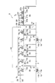
- FIG. 2 is an explanatory diagram showing the arrangement and the like of a plurality of fan filter units.
- the air flow is indicated by a solid arrow.
- FIG. 2 shows a part of each room in FIG. 1 (floor plan), and
- FIG. 5 shows the remaining rooms.
- FIGS. 2 and 5 are schematic cross-sectional views focusing on the flow of air, for example, air is guided from the preparation chamber R7 to the chamber C via the duct shaft DS2.
- the duct shaft DS1 shown in FIG. 2 is a space for guiding air from the preparation chamber R7 to the chamber C. Further, although not shown in FIG. 1, the duct shafts DS2 to DS5 are also spaces for guiding air from a predetermined room to the chamber C. These duct shafts DS1 to DS5 are formed by wind conduits (not shown) provided in a gap or the like between adjacent rooms.
- the air conditioning system S includes an air handling unit 50, fan filter units 1 to 11, and pressure sensors 31 to 36.
- the air handling unit 50 is a device that adjusts the temperature of air and the like.
- the air handling unit 50 includes a filter 51, a cooling coil 52, a fan 53, and an inverter 54.
- the filter 51 removes dust from the air sucked from the preparation chamber R7 via the duct shaft DS1.
- the cooling coil 52 is a heat exchanger in which heat exchange is performed between the air that has passed through the filter 51 and the refrigerant that passes through a heat transfer tube (not shown).
- the fan 53 is a blower that pumps the air heat-exchanged by the cooling coil 52 to the chamber C via the duct D1.
- the inverter 54 controls a motor (not shown) that is a drive source of the fan 53.
- the outlet side of the fan 53 and the chamber C are connected via a duct D1.
- the duct D1 is a wind conduit that guides air whose temperature and the like have been adjusted by the air handling unit 50 to the chamber C.
- a damper B1 is provided in the duct D1. Then, for example, the damper B1 is set to a predetermined opening degree during the trial run of the air conditioning system S, and is maintained at the predetermined opening degree during the subsequent air conditioning operation.
- the chamber C shown in FIG. 2 is a space provided between the downstream ends of the ducts D1 and D2 and each room such as the preparation room R7. Specifically, the chamber C is formed by the ceiling G of each room such as the preparation room R7, the upper plate Ta, and the side plates Tb and Tc.
- the upper plate Ta is provided at a position higher than the ceiling G, and the plate surface of the upper plate Ta is substantially parallel to the surface of the ceiling G.
- a side plate Tb is provided so as to connect the ceiling G and the edge of the upper plate Ta on one side in the lateral direction (left side of the paper surface).
- the side plate Tc is provided so as to connect the ceiling G and the edge of the upper plate Ta on the other side in the lateral direction (right side of the paper surface).
- the vertical distance between the ceiling G and the upper plate Ta is appropriately set at the design stage so as not to hinder the flow of air through the chamber C.
- the fan filter unit 1 (first unit) is a device that supplies air from the chamber C including the space behind the ceiling of the preparation room R7 (clean room) to the preparation room R7, and is embedded in the ceiling G.
- the fan filter unit 1 includes a control device (not shown) in addition to the air supply fan 1a (first fan) and the filter 1b (first filter) shown in FIG.
- the air supply fan 1a is a blower that supplies air from the chamber C to the preparation chamber R7, and is provided with a fan body and a fan motor, although not shown.
- a fan body of the air supply fan 1a for example, an axial fan such as a propeller fan is used.
- the fan motor of the air supply fan 1a for example, a DC motor is used.
- the DC motor described above may be a brushless DC motor or a DC motor with a brush.
- the filter 1b is a filter that removes dust from the air blown from the air supply fan 1a to the preparation chamber R7, and is provided on the blowing side of the air supply fan 1a.
- a filter 1b for example, HEPA (High Efficiency Particulate Air Filter) or ULPA (Ultra Low Penetration Air Filter) is used.
- the housing (not shown) accommodating the air supply fan 1a and the filter 1b is fitted into the opening (not shown) of the ceiling G of the preparation chamber R7 and fixed with metal fittings or the like.
- Another fan filter unit 2 provided on the ceiling G of the preparation chamber R7 has the same configuration as the fan filter unit 1 described above.
- the fan filter unit 3 (second unit) is a device that returns air through the chamber C of the preparation chamber R7 and exhausts the air from the preparation chamber R7.
- the "returning air” of the preparation chamber R7 means that at least a part of the air in the preparation chamber R7 is returned to the preparation chamber R7.
- the fan filter unit 3 is shown on the lower side of the floor F of the preparation chamber R7, but as shown in FIG. 1, a space adjacent to the preparation chamber R7 via the door Dp.
- a fan filter unit 3 is provided on the outside of the wall of R12.
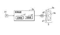
- the fan filter unit 3 includes a return air fan 3a (second fan) and a filter 3b (second filter), and also includes a control device 3c (not shown in FIG. 2, see FIG. 3). ) Is provided.
- FIG. 3 is a configuration diagram relating to the control of the fan filter unit 3.
- the return air fan 3a shown in FIG. 3 is a blower that returns air through the air chamber C (see FIG. 2) of the preparation chamber R7 and exhausts the air from the preparation chamber R7, and is a fan main body a1 and a fan motor. It is equipped with a2.
- As the fan body a1 of such a return air fan 3a for example, an axial fan such as a propeller fan is used.
- the fan motor a2 of the return air fan 3a for example, a DC motor is used.
- the control device 3c is a device that controls the fan motor a2 based on the detected value of the pressure sensor 31, and is arranged near the fan motor a2, for example.
- the control device 3c includes electronic circuits such as a CPU (Central Processing Unit), a ROM (Read Only Memory), a RAM (Random Access Memory), and various interfaces. Then, the program stored in the ROM is read out and expanded in the RAM, and the CPU executes various processes.
- a CPU Central Processing Unit
- ROM Read Only Memory
- RAM Random Access Memory
- the control device 3c includes a storage unit c1 and a control unit c2.
- a predetermined program is stored in advance in the storage unit c1.
- the control unit c2 predeterminedly controls the fan motor a2 of the return air fan 3a based on the detected value of the pressure sensor 31.
- a PLC Programmable Logic Controller: not shown
- connected to the control device 3c may be provided. Then, even if the control device 3c changes the upper limit value and the lower limit value of the rotation speed of the return air fan 3a to predetermined values based on the values input to the PLC (not shown) from other devices and sensors. Good.
- the filter 3b removes dust from the air sucked into the return air fan 3a from the preparation chamber R7 (see also FIG. 2), and is provided on the suction side of the return air fan 3a.
- a filter 3b for example, HEPA (High Efficiency Particulate Air Filter) or ULPA (Ultra Low Penetration Air Filter) is used. Since the filter 3b also functions as a resistor (air resistance) when air flows out from the preparation chamber R7, there is an advantage that the chamber pressure of the preparation chamber R7 can be easily maintained at a relatively high value.
- the housing (not shown) accommodating the return air fan 3a and the filter 3b is opened in the wall opening (not shown in FIG. 1) forming the space R12 (see FIG. 1). It is fitted and fixed with metal fittings or the like.
- the pressure sensor 31 shown in FIG. 3 is a sensor that detects the pressure in the preparation chamber R7 (see FIG. 2), and is provided in the preparation chamber R7. The detected value of the pressure sensor 31 is output to the control device 3c.
- the reference pressure for detecting the room pressure of the preparation room R7 the room pressure of a predetermined general room (not shown) provided outside each room of the air conditioning system S may be used.
- the rotation speed of the air supply fans 1a and 2a shown in FIG. 2 is a predetermined value (fixed value), while the rotation speed of the return air fan 3a is based on the detection value of the pressure sensor 31. , The case where it is changed as appropriate will be described.
- the air supply fans 1a and 2a and the return air fan 3a shown in FIG. 2 are often always driven during the air conditioning operation.
- the air volume (that is, rotation speed) of the air supply fans 1a and 2a is preset so that the air in the preparation chamber R7 is ventilated a predetermined number of times per unit time. The higher the ventilation rate per unit time, the higher the cleanliness of the preparation chamber R7.
- the return air fan 3a maintains the air taken in by the air supply fans 1a and 2a so as to exit from the preparation chamber R7, and the chamber pressure of the preparation chamber R7 is maintained at a predetermined set pressure (target value of the chamber pressure).
- the rotation speed is adjusted as appropriate.
- the gaps k1 and k2 shown in FIG. 2 are ventilation passages when air exits from the preparation chamber R7.
- One gap k1 is, for example, between the packing (not shown) at the lower end of the door Dq (see FIG. 1) that separates the preparation chamber R7 and the space R13 (see FIG. 1) and the floor surface of the preparation chamber R7. It is a gap of.
- the space R13 shown in FIG. 1 communicates with the suction side of the air handling unit 50 via the duct shaft DS1 (see FIG. 2). Further, the height position of the lower end of the packing of the door Dq can be adjusted so that the size of the gap k1 can be adjusted appropriately.
- the other gap k2 shown in FIG. 2 is, for example, between the packing (not shown) at the lower end of the door Dp that separates the preparation chamber R7 and the space R12 (see FIG. 1) and the floor surface of the preparation chamber R7. There is a gap.
- the space R12 shown in FIG. 1 communicates with the chamber C (see FIG. 2) via the duct shaft DS2 (see FIG. 2) and also communicates with the suction side of the return air fan 3a. Then, the height position of the packing of the door Dp can be adjusted so that the size of the gap k2 can be adjusted.
- the size (aperture ratio) of the gaps k1 and k2 is appropriately adjusted at the time of design and trial run based on the volume of the preparation chamber R7 as well as the target values such as the ventilation frequency and the chamber pressure.
- a thin plate h2 having a plurality of holes is provided at the upper end of the duct shaft DS2. Then, while the return air fan 3a is being driven, a part of the air guided from the preparation chamber R7 to the duct shaft DS2 through the gap k2 is returned to the chamber C through the plurality of holes of the thin plate h2 (that is,). It is supposed to be repatriated). In this way, by returning the air in the preparation chamber R7 through the chamber C, the highly clean air is reused for air conditioning in each chamber.
- the fan filter unit 2 (second unit) sucks air through a predetermined gap k2 provided in the wall W2 (or floor F) of the preparation chamber R7, and a part of the sucked air is used as the duct shaft DS2. It is arranged to evacuate the remaining air while returning it to chamber C via.
- the preparation chamber R7 communicates with and returns to the chamber C via the suction side of the air supply fans 1a and 2a. It communicates with the chamber C via the suction side of the air fan 3a. Then, as will be described next, the chamber pressure of the preparation chamber R7 is adjusted by controlling the return air fan 3a.
- the airlock AL1 has a higher chamber pressure than the preparation chamber R7, so that air flows from the airlock AL1 into the preparation chamber R7 and the chamber pressure of the preparation chamber R7. Rise slightly.
- the control unit c2 (see FIG. 3) is subjected to the fan motor a2 (see FIG. 3). Increase the rotation speed to a predetermined level.
- the increase width (and decrease width) of the rotation speed of the fan motor a2 is predeterminedly calculated based on a program stored in advance in the storage unit c1 (see FIG. 3).
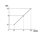
- FIG. 4 is a characteristic diagram showing the relationship between the rotation speed of the return air fan and the air volume.
- the horizontal axis of FIG. 4 is the rotation speed of the return air fan 3a (that is, the rotation speed of the fan motor a2), and the vertical axis is the air volume of the return air fan 3a.
- the higher the rotation speed of the return air fan 3a the larger the air volume.
- the rotation speed of the return air fan 3a and the air volume have a linear relationship (proportional relationship). Therefore, there is an advantage that the air volume can be finely adjusted by the return air fan 3a as compared with the case where the air volume is adjusted by using a damper (not shown) having a non-linear relationship between the opening degree and the air volume characteristic.
- the air supply fans 1a, 2a and the like have the same characteristics as those in FIG.
- the return air fan 3a is preset with a lower limit value N1 of its rotation speed and a lower limit value Q1 of an air volume corresponding thereto based on a predetermined specification.
- the upper limit value N2 of the rotation speed of the return air fan 3a and the upper limit value Q2 of the corresponding air volume are also set in advance.
- a specific numerical example thereof is 50 [m 3 / h]
- the air volume is adjusted by the return air fan 3a, which has a linear rotation speed-air volume characteristic, the air volume can be finely adjusted even near the upper and lower limits of the rotation speed.
- the chamber pressure of the preparation chamber R7 can be maintained with high accuracy while driving the air supply fans 1a and 2a (see FIG. 2) and the return air fans 3a (see FIG. 2) with a low air volume.
- the control unit c2 (see FIG. 3) is a fan motor.
- the rotation speed of a2 (see FIG. 3) is increased to a predetermined value.
- the air supply fan 2a is driven at a predetermined rotation speed (fixed value).
- the air volume of the return air fan 3a can be finely adjusted even in the vicinity of the lower limit value Q1 shown in FIG. 4, the chamber pressure of the preparation chamber R7 can be maintained with high accuracy even at a low air volume.
- the control unit c2 (see FIG. 3) is subjected to the fan motor a2 (see FIG. 3). Decrease the rotation speed to a predetermined level. As a result, in the preparation chamber R7, the temporarily lowered chamber pressure is returned to a predetermined target value. By such control, the fluctuation of the chamber pressure of the preparation chamber R7 is suppressed, and the chamber pressure is maintained near a predetermined target value.
- the pressure of the chamber C fluctuates slightly due to the return air to the chamber C by the return air fans 7a, 9a, 11a described later, but it adversely affects the maintenance of the chamber pressure in each chamber. It's almost nonexistent.
- a fan filter unit 4 is embedded in the ceiling G of the front chamber R9. Further, a pressure sensor 32 is provided in the front chamber R9. Then, based on the detected value of the pressure sensor 32, the rotation speed of the air supply fan 4a is controlled so as to maintain the chamber pressure of the front chamber R9 at a predetermined target value. Since the configuration and control of the air supply fan 4a are the same as those of the return air fan 3a described above, the description thereof will be omitted.
- FIG. 2 shows an arrow so as to pass from the floor F of the front chamber R9 to the lower side of the paper surface.
- the packing (not shown) at the lower end of the door Dw (see FIG. 1) and the front The air in the front chamber R9 is exhausted through the gap between the floor surface of the chamber R9 and the floor surface.
- the other anterior chamber R8 is not particularly provided on the exhaust side of the air from the front chamber R9.
- An air supply fan 6a (first fan) is embedded in the ceiling G of the airlock AL2 shown in FIG.
- a return air fan 7a (second fan) is embedded in the side wall of the airlock AL2.
- the airlock AL2 is provided with a pressure sensor 34 for detecting the chamber pressure. Then, while the air supply fan 6a is driven at a predetermined rotation speed (fixed value), the rotation speed of the return air fan 7a is controlled (changed) so as to maintain the chamber pressure of the airlock AL2 at a predetermined target value. It is supposed to be done.
- the air blown out from the return air fan 7a is returned to the chamber C through the duct shaft DS3 and the plurality of holes of the thin plate h3 in sequence.
- the airlock AL2 passes through the suction side of the air supply fan 6a (first fan) to the chamber. It communicates with C and also communicates with chamber C via the outlet side of the return air fan 7a (second fan).
- the configuration and control of the return air fan 7a are the same as those of the return air fan 3a used for air conditioning in the preparation room R7. Is.
- the room pressure of the airlock AL2 can be maintained with high accuracy, and air having a relatively high degree of cleanliness can be reused for air conditioning in each room.
- control of the room pressure of the airlock AL1 and the secondary changing room R6 is the same as the control of the room pressure of the preparation room R7. Therefore, detailed description of these will be omitted.
- the air conditioning of the remaining rooms not shown in FIG. 2 will be described.
- FIG. 5 is an explanatory diagram showing the arrangement and the like of a plurality of fan filter units.
- the ceiling G shown in FIG. 5 is the same as that shown in FIG. Further, the chamber C shown in FIG. 5 is also the same as that shown in FIG.
- the fan filter unit 12 (first unit) is a device that supplies air from the chamber C to the primary changing room R2, and is embedded in the ceiling G. Since the configuration of the fan filter unit 12 is the same as that of the fan filter unit 1 and the like (see FIG. 2) in the preparation chamber R7, the description thereof will be omitted.
- the fan filter unit 13 (second unit) is a device that exhausts air from the primary changing room R2. As described above, the example of FIG. 5 is different from the above-mentioned fan filter units 3, 7, 9, 11 (see FIG. 2) in that the fan filter unit 13 is not used for return air. Further, in FIG. 5, the fan filter unit 13 is shown on the lower side of the floor F of the primary changing room R2 for simplification, but as shown in FIG. 1, the primary changing room R2 and the outside are separated from each other. The fan filter unit 13 is embedded in the wall.
- the fan filter unit 13 includes a control device (not shown) in addition to the exhaust fan 13a (second fan) and the filter 13b (second filter) shown in FIG. Further, the primary changing room R2 is provided with a pressure sensor 37 for detecting the room pressure. Then, the control device (not shown) controls the rotation speed of the exhaust fan 13a so that the chamber pressure of the primary changing room R2 is set to a predetermined target value based on the detection value of the pressure sensor 37. There is.
- the fan filter unit 3 and 3 are included in the "second unit” having the “second fan” that returns air through the chamber C of the "clean room” and exhausts at least one of the exhaust from the "clean room".
- fan filter units 18, 22 are also included.
- the air conditioning of the detachable chamber R1, the anterior chambers R4, R5, and R11 shown in FIG. 5 is the same as that of the anterior chamber R9 (see FIG. 2), and thus the description thereof will be omitted.
- Fan filter units 20 to 22 are embedded in the ceiling G of the pretreatment chamber R3 shown in FIG.
- the suction sides of the air supply fans 20a and 21a of the fan filter units 20 and 21 communicate with the chamber C.
- the outlet side of the exhaust fan 22a of the fan filter unit 22 is open to the outside.
- a pressure sensor 43 is provided in the pretreatment chamber R3. Then, based on the detected value of the pressure sensor 43, the rotation speed of the exhaust fan 22a is controlled so as to maintain the chamber pressure of the pretreatment chamber R3 at a predetermined target value.
- a part of the air supplied to the pretreatment chamber R3 by driving the air supply fans 20a and 21a is discharged by the exhaust fan 22a. Further, the remaining air is guided to the suction side of the air handling unit (not shown) through the predetermined gap k3, the duct shaft DS6, and the duct D3 in this order.
- the duct D3 is a wind duct that guides air from the chamber C to the air handling unit (not shown). Further, the above-mentioned air handling unit (not shown) is a device that supplies air whose temperature and the like are adjusted through the duct D3.
- the opening degree of the damper B3 provided in the duct D3 is maintained in a predetermined state during a trial run or the like.
- the chamber pressure of the preparation chamber R7 (see FIG. 2) to which air is supplied from the air supply fans 1a and 2a (see FIG. 2) is maintained at a predetermined level by the control of the return air fan 3a.
- the configuration of the air conditioning system S can be simplified. Further, it becomes easy to provide a predetermined gas pipe (not shown) in the chamber C, or to route a communication line or a power line.
- the construction period when installing the air conditioning system S can be shortened, and the cost required for the installation can be reduced. It also makes it easier to handle cases where the installation space is limited, such as in a building with multiple facilities.
- the chamber pressure of the preparation chamber R7 (see FIG. 2) is adjusted by the return air fan 3a, the above-mentioned pressure loss and response delay hardly occur. Further, since the rotation speed-air volume characteristics of the return air fan 3a and the like are linear (see FIG. 4), the chamber pressure of the preparation chamber R7 can be maintained with high accuracy. The same can be said for each of the other rooms.
- the air conditioning system S can be applied.
- the structure and control for adjusting the room pressure are independent (completed). Therefore, the degree of freedom in designing the air conditioning system S is high, and expansion is easy. As described above, according to the present embodiment, it is possible to provide the air conditioning system S that maintains the room pressure of the clean room (preparation room R7, etc.) with high accuracy with a simple configuration, and contribute to social contribution.
- the air conditioning system S according to the present invention has been described above by embodiment, the present invention is not limited to these descriptions, and various modifications can be made.
- the chamber pressure of the preparation room R7 (see FIG. 2) is adjusted by the return air fan 3a
- the chamber pressure of the primary changing room R2 (see FIG. 5) is adjusted by the exhaust fan 13a, and the like.
- the exhaust fan 13a is adjusted by the exhaust fan 13a, and the like.
- the rotation speed may be changed), and the rotation speed of the "second fan” may be kept constant.
- the “control unit” reduces the rotation speed of the "first fan” to a predetermined value.
- the “control unit” increases the rotation speed of the "first fan” to a predetermined value. Even with such a configuration, the room pressure of the clean room can be maintained with high accuracy.
- control unit may control both the “first fan” and the “second fan” described above.
- the "control unit” rotates the “second fan” while reducing (or maintaining) the rotation speed of the "first fan", for example. Increase speed.
- the "control unit” increases (or maintains) the rotation speed of the "first fan” while decreasing the rotation speed of the "second fan”. In this way, the “control unit” may control the rotation speed of at least one of the "first fan” and the "second fan”. Even with such a configuration, the room pressure of the clean room can be maintained with high accuracy.
- the set pressure (target value of the room pressure) of any of the plurality of clean rooms adjacent to the self is set.
- There may be a predetermined clean room for example, the airlocks AL1 and AL2 shown in FIG. 1) having a pressure lower than the set pressure of.
- the filter 7b of the fan filter unit 7 on the return air side of the airlock AL2 also functions as a resistor in the air flow, so that the chamber pressure of the airlock AL2 is increased. It has the advantage of being easy to maintain at a relatively high value.
- three or more clean rooms separated by a wall provided with a door are provided, and among the three or more clean rooms, the set pressure (target value of the room pressure) of any of the plurality of clean rooms adjacent to the self is set.
- the set pressure target value of the room pressure
- the room pressure of each clean room is controlled independently, such a room arrangement is also possible.
- a clean room in which both return air and exhaust are performed by a "second fan” (for example, return air fan 3a: see FIG. 2) and another "second fan” (see FIG. 2).
- a clean room airlock AL2: see FIG. 2) in which the return air is returned by the return air fan 7a (see FIG. 2) may be mixed.
- exhausting is also performed by the return air fans 3a, 7a, etc., so that the pressure fluctuation of the chamber C is suppressed, and by extension, the chamber pressure of each chamber is further increased. Can be maintained with high accuracy.
- highly clean air can be reused.
- a clean room in which both return air and exhaust are performed by a "second fan” (for example, return air fan 3a: see FIG. 2) and another "second fan” (see FIG. 2).
- a clean room primary changing room R2: see FIG. 5 in which exhaust is performed by the exhaust fan 13a (see FIG. 5) may be mixed.
- the ventilation rate per unit time of the clean room where both return air and exhaust are performed is the clean room where only exhaust is performed (for example, primary changing). It may be set to be higher than the ventilation frequency of the chamber R2: see FIG. 5).
- a clean room in which air is returned by a "second fan” (for example, return air fan 7a: see FIG. 2) and another "second fan” (for example, exhaust fan 13a).
- a clean room primary changing room R2: see FIG. 5) in which exhaust is performed by (see FIG. 5) may be mixed.
- the pressure fluctuation of the chamber C is suppressed, and the chamber pressure of each chamber can be maintained with higher accuracy.
- each fan including the air supply fans 1a and 2a and the return air fan 3a has been described, but the present invention is not limited to this. That is, as each fan including the air supply fans 1a and 2a and the return air fan 3a, a centrifugal fan or the like may be used in addition to the mixed flow fan and the cross flow fan.
- each fan including the air supply fans 1a and 2a and the return air fan 3a is a DC motor
- an AC motor such as a synchronous motor may be used as a drive source for each fan including the air supply fans 1a and 2a and the return air fan 3a.
- HEPA or ULPA is used as the filter 1b included in the fan filter unit 1
- the present invention is not limited to this.
- other types of filters such as a filter using PTFE (ethylene tetrafluoride resin) may be used.
- the control device of the air supply fans 1a and 2a (not shown) and the control device 3c of the return air fan 3a are separately provided.
- the chamber pressure of the pretreatment chamber R3 (see FIG. 1) and the preparation chamber R7 (see FIG. 1) in which the sample is handled is the chamber pressure of each chamber other than the airlock AL1 and AL2 (see FIG. 1).
- higher pressure that is, positive pressure
- the embodiment can be applied even when a clean room having a lower room pressure (that is, negative pressure) than other rooms is provided as a work space for a production process such as a medical facility or a laboratory animal facility.
- the air conditioning system S is used in the regenerative medicine facility has been described as an example, but the present invention is not limited to this. That is, the embodiment can be applied to various other fields such as manufacturing of industrial products, food industry, and manufacturing of pharmaceutical products.
- each embodiment is described in detail in order to explain the present invention in an easy-to-understand manner, and is not necessarily limited to the one including all the configurations described. Further, it is possible to add / delete / replace a part of the configuration of the embodiment with another configuration.
- the above-mentioned mechanism and configuration show what is considered necessary for explanation, and do not necessarily show all the mechanisms and configurations in the product.
- Fan filter unit 3,7,9,11,13,18,22 Fan filter unit (second unit) 1a, 2a, 4a, 5a, 6a, 8a, 10a, 12a, 14a, 15a, 16a, 17a, 19a, 20a, 21a Air supply fan (first fan) 1b, 2b, 4b, 5b, 6b, 8b, 10b, 12b, 14b, 15b, 16b, 17b, 19b, 20b, 21b filters (first filter) 3a, 7a, 9a, 11a Return air fan (second fan) 3b, 7b, 9b, 11b filter (second filter) 13a, 18a, 22a Exhaust fan (second fan) 13b, 18b, 22b filter (second filter) 31, 32, 33, 34, 35, 36, 37, 38, 39, 40, 41, 42, 43 Pressure sensor 3c Control device a1 Fan body a2 Fan motor (DC)
Landscapes
- Engineering & Computer Science (AREA)
- Chemical & Material Sciences (AREA)
- Combustion & Propulsion (AREA)
- Mechanical Engineering (AREA)
- General Engineering & Computer Science (AREA)
- Physics & Mathematics (AREA)
- Fluid Mechanics (AREA)
- Ventilation (AREA)
- Air Conditioning Control Device (AREA)
- Central Air Conditioning (AREA)
- Sorption Type Refrigeration Machines (AREA)
Abstract
Description
図1は、実施形態に係る空調システムSの各部屋の間取りを示す説明図である。
なお、図1では、所定のドア(例えば、ドアDm)が開かれた場合に空気が流れる向きを白抜きの破線矢印で示している。本実施形態では、主に、各部屋の室圧の調整について説明するが、室圧の他に空気の温度や湿度を調整する場合も「空調」に含まれるものとする。また、室圧のみの調整も「空調」に含まれるものとする。
なお、図2では、空気の流れを実線矢印で示している。また、図2には、図1(間取り図)の各部屋のうちの一部を図示し、残りの部屋については図5に示している。これらの図2、図5は、例えば、調製室R7からダクトシャフトDS2を介して、チャンバCに空気が導かれるといったように、空気の流れに着目した模式的な断面図になっている。
エアハンドリングユニット50は、空気の温度等を調整する装置である。図2に示すように、エアハンドリングユニット50は、フィルタ51と、冷却コイル52と、ファン53と、インバータ54と、を備えている。
図3に示す還気ファン3aは、調製室R7の空気のチャンバC(図2参照)を介した還気、及び、調製室R7からの排気を行う送風機であり、ファン本体a1と、ファンモータa2と、を備えている。このような還気ファン3aのファン本体a1として、例えば、プロペラファンといった軸流ファンが用いられる。また、還気ファン3aのファンモータa2として、例えば、直流モータが用いられる。
なお、制御装置3cに接続されるPLC(Programmable Logic Controller:図示せず)を設けるようにしてもよい。そして、他の機器やセンサ類からPLC(図示せず)に入力される値に基づき、制御装置3cが、還気ファン3aの回転速度の上限値・下限値を所定に変更するようにしてもよい。
そして、還気ファン3a及びフィルタ3bを収容する筐体(図示せず)が、前記した空間R12(図1参照)を形成している壁の開口部(図1では符号を図示せず)に嵌め込まれて、金具等で固定されている。
なお、図4の横軸は、還気ファン3aの回転速度(つまり、ファンモータa2の回転速度)であり、縦軸は、還気ファン3aの風量である。図4に示すように、還気ファン3aの回転速度が高いほど、その風量も大きくなる。また、還気ファン3aの回転速度と風量とは、線形の関係(比例関係)になっている。したがって、開度-風量特性が非線形の関係であるダンパ(図示せず)を用いて風量を調整する場合に比べて、還気ファン3aによって風量の微調整を行いやすいという利点がある。なお、還気ファン3aの他、給気ファン1a,2a等も図4と同様の特性を有している。
なお、図5に示す天井Gは、図2に示したものと同一である。また、図5に示すチャンバCも、図2に示したものと同一である。
ファンフィルタユニット12(第1ユニット)は、チャンバCから1次更衣室R2への給気を行う機器であり、天井Gに埋設されている。なお、ファンフィルタユニット12の構成は、調製室R7のファンフィルタユニット1等(図2参照)と同様であるから、説明を省略する。
本実施形態によれば、例えば、給気ファン1a,2a(図2参照)から空気を供給される調製室R7(図2参照)の室圧が、還気ファン3aの制御によって所定に維持される。したがって、調製室R7に空気を導くダクト(図示せず)や、調製室R7から外部に空気を導くダクト(図示せず)を特に設ける必要がなく、空調システムSの構成を簡素化できる。また、チャンバCに所定のガス配管(図示せず)を設けたり、通信線や電力線を引き回したりすることが容易になる。
以上、本発明に係る空調システムSについて実施形態により説明したが、本発明はこれらの記載に限定されるものではなく、種々の変更を行うことができる。
例えば、実施形態では、調製室R7(図2参照)の室圧を還気ファン3aで調整する場合や、1次更衣室R2(図5参照)の室圧を排気ファン13aで調整する場合等について説明したが、これに限らない。
すなわち、クリーンルームへの給気を行う「第1ファン」と、クリーンルームの還気及び排気のうち少なくとも一方を行う「第2ファン」と、が設けられる構成において、前記した「第1ファン」を制御し(回転速度を変化させ)、「第2ファン」の回転速度を一定にしてもよい。このような構成において、クリーンルームの室圧が目標値を超えた場合、「制御部」は、「第1ファン」の回転速度を所定に低下させる。一方、クリーンルームの室圧が目標値を下回った場合、「制御部」は、「第1ファン」の回転速度を所定に上昇させる。このような構成でも、クリーンルームの室圧を高精度に維持できる。
さらに、このような構成において、還気及び排気の両方が行われるクリーンルーム(例えば、調製室R7:図2参照)の単位時間当たりの換気回数が、排気のみが行われるクリーンルーム(例えば、1次更衣室R2:図5参照)の換気回数よりも多いようにしてもよい。これによって、例えば、清浄度の高い調製室R7の空気の一部を各室の空調に再利用できる。
また、前記した機構や構成は説明上必要と考えられるものを示しており、製品上必ずしも全ての機構や構成を示しているとは限らない。
3,7,9,11,13,18,22 ファンフィルタユニット(第2ユニット)
1a,2a,4a,5a,6a,8a,10a,12a,14a,15a,16a,17a,19a,20a,21a 給気ファン(第1ファン)
1b,2b,4b,5b,6b,8b,10b,12b,14b,15b,16b,17b,19b,20b,21b フィルタ(第1フィルタ)
3a,7a,9a,11a 還気ファン(第2ファン)
3b,7b,9b,11b フィルタ(第2フィルタ)
13a,18a,22a 排気ファン(第2ファン)
13b,18b,22b フィルタ(第2フィルタ)
31,32,33,34,35,36,37,38,39,40,41,42,43 圧力センサ
3c 制御装置
a1 ファン本体
a2 ファンモータ(直流モータ)
c1 記憶部
c2 制御部
AL1,AL2 エアロック(クリーンルーム)
C チャンバ
Da,Db,Dc,Dd,De,Df,Dg,Dh,Di,Dj,Dk,Dm,Dn,Do,Dp,Dq,Dr,Ds,Dt,Du,Dv,Dw,Dx,Dy,Dz,Dα,Dβ,Dγ ドア
DS1,DS2,DS3,DS4,DS5,DS6 ダクトシャフト
F 床
G 天井
k2 隙間
R1 着脱室(クリーンルーム)
R2 1次更衣室(クリーンルーム)
R3 前処理室(クリーンルーム)
R4,R5,R8,R9,R11 前室(クリーンルーム)
R6 2次更衣室(クリーンルーム)
R7 調製室(クリーンルーム)
R10 脱衣室(クリーンルーム)
S 空調システム
W1 壁
Claims (8)
- クリーンルームの天井裏の空間を含むチャンバから前記クリーンルームへの給気を行う第1ファンを有する第1ユニットと、
前記クリーンルームの空気の前記チャンバを介した還気、及び、前記クリーンルームからの排気のうち少なくとも一方を行う第2ファンを有する第2ユニットと、を備えるとともに、
前記クリーンルームに設けられる圧力センサと、
前記圧力センサの検出値に基づいて、前記第1ファン及び前記第2ファンのうち少なくとも一方を制御する制御部と、を備えること
を特徴とする空調システム。 - 前記第2ファンが、前記クリーンルームの還気及び排気の両方を行う場合において、
前記第2ユニットは、前記クリーンルームの壁又は床に設けられた所定の隙間を介して空気を吸い込み、吸い込んだ空気の一部をダクトシャフトを介して前記チャンバに戻し、残りの空気を排気するように配置され、
前記クリーンルームは、前記第1ファンの吸込側を介して、前記チャンバに連通するとともに、前記第2ファンの吸込側を介して、前記チャンバに連通していること
を特徴とする請求項1に記載の空調システム。 - 前記第2ファンが、前記クリーンルームの還気を行う場合において、
前記クリーンルームは、前記第1ファンの吸込側を介して、前記チャンバに連通するとともに、前記第2ファンの吹出側を介して、前記チャンバに連通していること
を特徴とする請求項1に記載の空調システム。 - 前記第1ユニットは、前記第1ファンから前記クリーンルームに吹き出される空気から塵埃を除去する第1フィルタを備え、
前記第2ユニットは、前記クリーンルームから前記第2ファンに吸い込まれる空気から塵埃を除去する第2フィルタを備えること
を特徴とする請求項1に記載の空調システム。 - ドアが設けられた壁で仕切られる3つ以上の前記クリーンルームが設けられ、
3つ以上の前記クリーンルームのうち、自身に隣り合う複数のクリーンルームのいずれの設定圧力も、自身の設定圧力よりも低い所定のクリーンルームが存在していること
を特徴とする請求項4に記載の空調システム。 - ドアが設けられた壁で仕切られる3つ以上の前記クリーンルームが設けられ、
3つ以上の前記クリーンルームのうち、自身に隣り合う複数のクリーンルームのいずれの設定圧力も、自身の設定圧力よりも高い所定のクリーンルームが存在していること
を特徴とする請求項4に記載の空調システム。 - 前記第1フィルタ及び前記第2フィルタは、それぞれ、HEPA(High Efficiency Particulate Air Filter)、又は、ULPA(Ultra Low Penetration Air Filter)であること
を特徴とする請求項4に記載の空調システム。 - 前記第1ファン及び前記第2ファンの駆動源は、それぞれ、直流モータであること
を特徴とする請求項1に記載の空調システム。
Priority Applications (9)
| Application Number | Priority Date | Filing Date | Title |
|---|---|---|---|
| PCT/JP2019/047441 WO2021111550A1 (ja) | 2019-12-04 | 2019-12-04 | 空調システム |
| CA3209498A CA3209498A1 (en) | 2019-12-04 | 2019-12-04 | Air conditioning system |
| US17/760,708 US11649975B2 (en) | 2019-12-04 | 2019-12-04 | Air conditioning system |
| JP2021562255A JP7181425B2 (ja) | 2019-12-04 | 2019-12-04 | 空調システム |
| CA3150088A CA3150088C (en) | 2019-12-04 | 2019-12-04 | Air conditioning system |
| CN201980099880.3A CN114341559A (zh) | 2019-12-04 | 2019-12-04 | 空气调节系统 |
| EP19954717.5A EP4071415A4 (en) | 2019-12-04 | 2019-12-04 | CLIMATE CONTROL SYSTEM |
| JP2022183115A JP7482195B2 (ja) | 2019-12-04 | 2022-11-16 | 空調システム |
| US18/125,819 US20230228433A1 (en) | 2019-12-04 | 2023-03-24 | Air Conditioning System |
Applications Claiming Priority (1)
| Application Number | Priority Date | Filing Date | Title |
|---|---|---|---|
| PCT/JP2019/047441 WO2021111550A1 (ja) | 2019-12-04 | 2019-12-04 | 空調システム |
Related Child Applications (2)
| Application Number | Title | Priority Date | Filing Date |
|---|---|---|---|
| US17/760,708 A-371-Of-International US11649975B2 (en) | 2019-12-04 | 2019-12-04 | Air conditioning system |
| US18/125,819 Continuation US20230228433A1 (en) | 2019-12-04 | 2023-03-24 | Air Conditioning System |
Publications (1)
| Publication Number | Publication Date |
|---|---|
| WO2021111550A1 true WO2021111550A1 (ja) | 2021-06-10 |
Family
ID=76221157
Family Applications (1)
| Application Number | Title | Priority Date | Filing Date |
|---|---|---|---|
| PCT/JP2019/047441 WO2021111550A1 (ja) | 2019-12-04 | 2019-12-04 | 空調システム |
Country Status (6)
| Country | Link |
|---|---|
| US (2) | US11649975B2 (ja) |
| EP (1) | EP4071415A4 (ja) |
| JP (2) | JP7181425B2 (ja) |
| CN (1) | CN114341559A (ja) |
| CA (2) | CA3150088C (ja) |
| WO (1) | WO2021111550A1 (ja) |
Cited By (2)
| Publication number | Priority date | Publication date | Assignee | Title |
|---|---|---|---|---|
| CN114919726A (zh) * | 2022-06-02 | 2022-08-19 | 江南造船(集团)有限责任公司 | 船舶空调通风系统及船舶 |
| WO2023170808A1 (ja) * | 2022-03-09 | 2023-09-14 | 日立グローバルライフソリューションズ株式会社 | クリーンルーム施設 |
Families Citing this family (1)
| Publication number | Priority date | Publication date | Assignee | Title |
|---|---|---|---|---|
| US11674709B2 (en) * | 2020-03-19 | 2023-06-13 | Fh Alliance Inc. | Air conditioning system |
Citations (6)
| Publication number | Priority date | Publication date | Assignee | Title |
|---|---|---|---|---|
| JP2000337675A (ja) * | 1999-05-25 | 2000-12-08 | Takasago Thermal Eng Co Ltd | 低露点のクリーンルーム装置 |
| JP2009058191A (ja) * | 2007-08-31 | 2009-03-19 | Hitachi Plant Technologies Ltd | バイオ処理施設の空調システム |
| JP2013240358A (ja) * | 2013-08-26 | 2013-12-05 | Regene Pharm:Kk | ユニット型細胞培養施設 |
| JP2016117003A (ja) * | 2014-12-19 | 2016-06-30 | 日本エアーテック株式会社 | アイソレータ |
| JP2017048941A (ja) * | 2015-08-31 | 2017-03-09 | 株式会社日立製作所 | クリーンルーム用空調システム及びそれに用いられる排気ユニット |
| JP2017125641A (ja) * | 2016-01-13 | 2017-07-20 | 株式会社日立製作所 | クリーンルーム用排気ユニット及びそれを備えるクリーンルーム用空調システム |
Family Cites Families (28)
| Publication number | Priority date | Publication date | Assignee | Title |
|---|---|---|---|---|
| US3122201A (en) * | 1960-05-05 | 1964-02-25 | Carrier Corp | Air conditioning system |
| JPS6172947A (ja) * | 1984-09-18 | 1986-04-15 | Takasago Thermal Eng Co Ltd | クリ−ンル−ムの形成法およびこの方法に使用する空気調和設備ユニツト |
| JPS625031A (ja) | 1985-06-28 | 1987-01-12 | Kajima Corp | 部分的に清浄度の異なるクリ−ンル−ム |
| JPH03291436A (ja) * | 1990-04-05 | 1991-12-20 | N M B Semiconductor:Kk | 半導体製造工場のクリーンルーム |
| JPH05149605A (ja) * | 1991-11-30 | 1993-06-15 | Toshiba Corp | 空気調和機 |
| JPH05322248A (ja) * | 1992-05-21 | 1993-12-07 | Matsushita Electric Ind Co Ltd | クリーンルーム与圧調整方法 |
| US6159421A (en) * | 1995-10-17 | 2000-12-12 | Ebara Corporation | Method of cleaning gases |
| JPH1096332A (ja) | 1996-09-20 | 1998-04-14 | Mitsubishi Electric Corp | クリーンルーム |
| JP3090088B2 (ja) * | 1997-02-07 | 2000-09-18 | 富士電機株式会社 | クリーンルームのファンフィルタユニット |
| JP3832612B2 (ja) * | 1997-07-16 | 2006-10-11 | 忠弘 大見 | クリーンルームにおける消火方法及びその装置 |
| CN1241701A (zh) * | 1998-06-25 | 2000-01-19 | 日本电气株式会社 | 减少循环空气压力损失来减少耗电量的空调装置和方法 |
| JP3287337B2 (ja) * | 1999-07-14 | 2002-06-04 | 日本電気株式会社 | ファン・フィルタ・ユニット |
| JP2001056140A (ja) | 1999-08-18 | 2001-02-27 | Takenaka Komuten Co Ltd | クリーンルーム |
| JP3476395B2 (ja) * | 1999-09-24 | 2003-12-10 | Necエレクトロニクス株式会社 | クリーンルーム及びクリーンルームの空調方法 |
| JP2001298068A (ja) * | 2000-04-18 | 2001-10-26 | Natl Inst Of Advanced Industrial Science & Technology Meti | 局所清浄化法及び局所清浄化加工処理装置 |
| JP4221539B2 (ja) | 2000-06-23 | 2009-02-12 | 株式会社日立プラントテクノロジー | クリーンルーム設備 |
| JP2002147811A (ja) | 2000-11-08 | 2002-05-22 | Sharp Corp | クリーンルーム |
| US8827780B1 (en) * | 2001-12-28 | 2014-09-09 | Huntair, Inc. | Fan coil block and grid configuration system |
| DE102004005342B4 (de) | 2004-02-04 | 2006-01-26 | Khs Maschinen- Und Anlagenbau Ag | Anlage zum aseptischen Abfüllen eines flüssigen Füllgutes |
| JP2006125812A (ja) | 2004-09-29 | 2006-05-18 | Matsushita Electric Ind Co Ltd | クリーンルーム設備及びクリーンルームの室圧制御方法 |
| JP4632806B2 (ja) * | 2005-02-18 | 2011-02-16 | 三洋電機株式会社 | 細胞培養施設 |
| SG136834A1 (en) * | 2006-04-28 | 2007-11-29 | Kyodo Allied Ind Ltd | A method and apparatus for maintaining air characteristics in an air ventilated facility using fan filter units |
| JP2011047561A (ja) | 2009-08-26 | 2011-03-10 | Shimizu Corp | クリーンルーム施設及び外調機 |
| JP5498863B2 (ja) | 2010-06-05 | 2014-05-21 | 株式会社竹中工務店 | クリーンルーム施設及びそのゾーンニング方法 |
| WO2012112775A2 (en) * | 2011-02-16 | 2012-08-23 | Fiorita John L Jr | Clean room control system and method |
| CN108019855B (zh) * | 2017-11-15 | 2020-12-29 | 同济大学 | 全解耦式净化空调系统 |
| US11131467B2 (en) * | 2019-04-11 | 2021-09-28 | Gene Osheroff | HVAC system with volume modulating valve |
| CN113692516B (zh) * | 2019-04-15 | 2023-04-04 | 大金工业株式会社 | 供气系统 |
-
2019
- 2019-12-04 US US17/760,708 patent/US11649975B2/en active Active
- 2019-12-04 WO PCT/JP2019/047441 patent/WO2021111550A1/ja unknown
- 2019-12-04 CA CA3150088A patent/CA3150088C/en active Active
- 2019-12-04 EP EP19954717.5A patent/EP4071415A4/en active Pending
- 2019-12-04 JP JP2021562255A patent/JP7181425B2/ja active Active
- 2019-12-04 CA CA3209498A patent/CA3209498A1/en active Pending
- 2019-12-04 CN CN201980099880.3A patent/CN114341559A/zh active Pending
-
2022
- 2022-11-16 JP JP2022183115A patent/JP7482195B2/ja active Active
-
2023
- 2023-03-24 US US18/125,819 patent/US20230228433A1/en active Pending
Patent Citations (6)
| Publication number | Priority date | Publication date | Assignee | Title |
|---|---|---|---|---|
| JP2000337675A (ja) * | 1999-05-25 | 2000-12-08 | Takasago Thermal Eng Co Ltd | 低露点のクリーンルーム装置 |
| JP2009058191A (ja) * | 2007-08-31 | 2009-03-19 | Hitachi Plant Technologies Ltd | バイオ処理施設の空調システム |
| JP2013240358A (ja) * | 2013-08-26 | 2013-12-05 | Regene Pharm:Kk | ユニット型細胞培養施設 |
| JP2016117003A (ja) * | 2014-12-19 | 2016-06-30 | 日本エアーテック株式会社 | アイソレータ |
| JP2017048941A (ja) * | 2015-08-31 | 2017-03-09 | 株式会社日立製作所 | クリーンルーム用空調システム及びそれに用いられる排気ユニット |
| JP2017125641A (ja) * | 2016-01-13 | 2017-07-20 | 株式会社日立製作所 | クリーンルーム用排気ユニット及びそれを備えるクリーンルーム用空調システム |
Cited By (2)
| Publication number | Priority date | Publication date | Assignee | Title |
|---|---|---|---|---|
| WO2023170808A1 (ja) * | 2022-03-09 | 2023-09-14 | 日立グローバルライフソリューションズ株式会社 | クリーンルーム施設 |
| CN114919726A (zh) * | 2022-06-02 | 2022-08-19 | 江南造船(集团)有限责任公司 | 船舶空调通风系统及船舶 |
Also Published As
| Publication number | Publication date |
|---|---|
| US20220349594A1 (en) | 2022-11-03 |
| JP7482195B2 (ja) | 2024-05-13 |
| CA3209498A1 (en) | 2021-06-10 |
| JP7181425B2 (ja) | 2022-11-30 |
| US20230228433A1 (en) | 2023-07-20 |
| CN114341559A (zh) | 2022-04-12 |
| JPWO2021111550A1 (ja) | 2021-06-10 |
| EP4071415A4 (en) | 2023-08-02 |
| EP4071415A1 (en) | 2022-10-12 |
| JP2023015305A (ja) | 2023-01-31 |
| CA3150088C (en) | 2023-10-10 |
| US11649975B2 (en) | 2023-05-16 |
| CA3150088A1 (en) | 2021-06-10 |
Similar Documents
| Publication | Publication Date | Title |
|---|---|---|
| JP7482195B2 (ja) | 空調システム | |
| KR102128654B1 (ko) | 음압형 특수시설의 공기조화시스템 | |
| US20150011153A1 (en) | Ventilation device for clean room applications | |
| CN112739958B (zh) | 空调装置以及送风风扇的转速调节方法 | |
| JP6505551B2 (ja) | クリーンルーム用排気ユニット | |
| WO2013073165A1 (ja) | 給排型換気装置 | |
| CN113465073A (zh) | 通风系统的控制方法及通风系统 | |
| JP7046642B2 (ja) | クリーンルーム及びクリーンルームの排気量調整方法 | |
| WO2022254705A1 (ja) | 空調システム | |
| KR101311181B1 (ko) | 공기조화시스템 | |
| JP5785633B2 (ja) | 給気装置 | |
| JP2014070748A (ja) | クリーンルームの区画方法、クリーンルーム | |
| JP2012102999A (ja) | 室圧制御装置 | |
| JP2005326093A (ja) | 簡易型バイオクリーンルーム | |
| JP2017003223A (ja) | ダクト型空気調和機の室内機 | |
| JP3516507B2 (ja) | クリーンルームシステム | |
| JP2010025516A (ja) | 空調機 | |
| JP2018066550A (ja) | 空調機送風口の割当て可変構造 | |
| WO2023170808A1 (ja) | クリーンルーム施設 | |
| JP2023089847A (ja) | 空調システム | |
| JP7332290B2 (ja) | クリーンルームシステム及び空気排出方法 | |
| JP7454842B2 (ja) | 空調箱及び空調システム | |
| CN114556028B (zh) | 用于配置hvac系统的改进的方法和系统 | |
| Zaki et al. | Overview of HVAC system: operational significance of HVAC provision for pharmaceutical facilities | |
| JP2022052815A (ja) | 空調ユニット |
Legal Events
| Date | Code | Title | Description |
|---|---|---|---|
| 121 | Ep: the epo has been informed by wipo that ep was designated in this application |
Ref document number: 19954717 Country of ref document: EP Kind code of ref document: A1 |
|
| ENP | Entry into the national phase |
Ref document number: 2021562255 Country of ref document: JP Kind code of ref document: A |
|
| ENP | Entry into the national phase |
Ref document number: 3150088 Country of ref document: CA |
|
| NENP | Non-entry into the national phase |
Ref country code: DE |
|
| ENP | Entry into the national phase |
Ref document number: 2019954717 Country of ref document: EP Effective date: 20220704 |