WO2021106914A1 - 樹脂発泡体 - Google Patents
樹脂発泡体 Download PDFInfo
- Publication number
- WO2021106914A1 WO2021106914A1 PCT/JP2020/043763 JP2020043763W WO2021106914A1 WO 2021106914 A1 WO2021106914 A1 WO 2021106914A1 JP 2020043763 W JP2020043763 W JP 2020043763W WO 2021106914 A1 WO2021106914 A1 WO 2021106914A1
- Authority
- WO
- WIPO (PCT)
- Prior art keywords
- resin foam
- resin
- polyolefin
- weight
- foam
- Prior art date
- Legal status (The legal status is an assumption and is not a legal conclusion. Google has not performed a legal analysis and makes no representation as to the accuracy of the status listed.)
- Ceased
Links
Images
Classifications
-
- C—CHEMISTRY; METALLURGY
- C08—ORGANIC MACROMOLECULAR COMPOUNDS; THEIR PREPARATION OR CHEMICAL WORKING-UP; COMPOSITIONS BASED THEREON
- C08J—WORKING-UP; GENERAL PROCESSES OF COMPOUNDING; AFTER-TREATMENT NOT COVERED BY SUBCLASSES C08B, C08C, C08F, C08G or C08H
- C08J9/00—Working-up of macromolecular substances to porous or cellular articles or materials; After-treatment thereof
- C08J9/04—Working-up of macromolecular substances to porous or cellular articles or materials; After-treatment thereof using blowing gases generated by a previously added blowing agent
- C08J9/12—Working-up of macromolecular substances to porous or cellular articles or materials; After-treatment thereof using blowing gases generated by a previously added blowing agent by a physical blowing agent
- C08J9/122—Hydrogen, oxygen, CO2, nitrogen or noble gases
-
- B—PERFORMING OPERATIONS; TRANSPORTING
- B32—LAYERED PRODUCTS
- B32B—LAYERED PRODUCTS, i.e. PRODUCTS BUILT-UP OF STRATA OF FLAT OR NON-FLAT, e.g. CELLULAR OR HONEYCOMB, FORM
- B32B27/00—Layered products comprising a layer of synthetic resin
- B32B27/32—Layered products comprising a layer of synthetic resin comprising polyolefins
-
- B—PERFORMING OPERATIONS; TRANSPORTING
- B32—LAYERED PRODUCTS
- B32B—LAYERED PRODUCTS, i.e. PRODUCTS BUILT-UP OF STRATA OF FLAT OR NON-FLAT, e.g. CELLULAR OR HONEYCOMB, FORM
- B32B5/00—Layered products characterised by the non- homogeneity or physical structure, i.e. comprising a fibrous, filamentary, particulate or foam layer; Layered products characterised by having a layer differing constitutionally or physically in different parts
- B32B5/18—Layered products characterised by the non- homogeneity or physical structure, i.e. comprising a fibrous, filamentary, particulate or foam layer; Layered products characterised by having a layer differing constitutionally or physically in different parts characterised by features of a layer of foamed material
-
- C—CHEMISTRY; METALLURGY
- C08—ORGANIC MACROMOLECULAR COMPOUNDS; THEIR PREPARATION OR CHEMICAL WORKING-UP; COMPOSITIONS BASED THEREON
- C08J—WORKING-UP; GENERAL PROCESSES OF COMPOUNDING; AFTER-TREATMENT NOT COVERED BY SUBCLASSES C08B, C08C, C08F, C08G or C08H
- C08J9/00—Working-up of macromolecular substances to porous or cellular articles or materials; After-treatment thereof
- C08J9/0014—Use of organic additives
- C08J9/0023—Use of organic additives containing oxygen
-
- C—CHEMISTRY; METALLURGY
- C08—ORGANIC MACROMOLECULAR COMPOUNDS; THEIR PREPARATION OR CHEMICAL WORKING-UP; COMPOSITIONS BASED THEREON
- C08J—WORKING-UP; GENERAL PROCESSES OF COMPOUNDING; AFTER-TREATMENT NOT COVERED BY SUBCLASSES C08B, C08C, C08F, C08G or C08H
- C08J9/00—Working-up of macromolecular substances to porous or cellular articles or materials; After-treatment thereof
- C08J9/0061—Working-up of macromolecular substances to porous or cellular articles or materials; After-treatment thereof characterized by the use of several polymeric components
-
- C—CHEMISTRY; METALLURGY
- C08—ORGANIC MACROMOLECULAR COMPOUNDS; THEIR PREPARATION OR CHEMICAL WORKING-UP; COMPOSITIONS BASED THEREON
- C08J—WORKING-UP; GENERAL PROCESSES OF COMPOUNDING; AFTER-TREATMENT NOT COVERED BY SUBCLASSES C08B, C08C, C08F, C08G or C08H
- C08J9/00—Working-up of macromolecular substances to porous or cellular articles or materials; After-treatment thereof
- C08J9/0066—Use of inorganic compounding ingredients
-
- C—CHEMISTRY; METALLURGY
- C08—ORGANIC MACROMOLECULAR COMPOUNDS; THEIR PREPARATION OR CHEMICAL WORKING-UP; COMPOSITIONS BASED THEREON
- C08J—WORKING-UP; GENERAL PROCESSES OF COMPOUNDING; AFTER-TREATMENT NOT COVERED BY SUBCLASSES C08B, C08C, C08F, C08G or C08H
- C08J9/00—Working-up of macromolecular substances to porous or cellular articles or materials; After-treatment thereof
- C08J9/0095—Mixtures of at least two compounding ingredients belonging to different one-dot groups
-
- C—CHEMISTRY; METALLURGY
- C08—ORGANIC MACROMOLECULAR COMPOUNDS; THEIR PREPARATION OR CHEMICAL WORKING-UP; COMPOSITIONS BASED THEREON
- C08J—WORKING-UP; GENERAL PROCESSES OF COMPOUNDING; AFTER-TREATMENT NOT COVERED BY SUBCLASSES C08B, C08C, C08F, C08G or C08H
- C08J9/00—Working-up of macromolecular substances to porous or cellular articles or materials; After-treatment thereof
- C08J9/04—Working-up of macromolecular substances to porous or cellular articles or materials; After-treatment thereof using blowing gases generated by a previously added blowing agent
- C08J9/12—Working-up of macromolecular substances to porous or cellular articles or materials; After-treatment thereof using blowing gases generated by a previously added blowing agent by a physical blowing agent
-
- C—CHEMISTRY; METALLURGY
- C09—DYES; PAINTS; POLISHES; NATURAL RESINS; ADHESIVES; COMPOSITIONS NOT OTHERWISE PROVIDED FOR; APPLICATIONS OF MATERIALS NOT OTHERWISE PROVIDED FOR
- C09J—ADHESIVES; NON-MECHANICAL ASPECTS OF ADHESIVE PROCESSES IN GENERAL; ADHESIVE PROCESSES NOT PROVIDED FOR ELSEWHERE; USE OF MATERIALS AS ADHESIVES
- C09J7/00—Adhesives in the form of films or foils
- C09J7/20—Adhesives in the form of films or foils characterised by their carriers
- C09J7/22—Plastics; Metallised plastics
- C09J7/26—Porous or cellular plastics
-
- C—CHEMISTRY; METALLURGY
- C08—ORGANIC MACROMOLECULAR COMPOUNDS; THEIR PREPARATION OR CHEMICAL WORKING-UP; COMPOSITIONS BASED THEREON
- C08J—WORKING-UP; GENERAL PROCESSES OF COMPOUNDING; AFTER-TREATMENT NOT COVERED BY SUBCLASSES C08B, C08C, C08F, C08G or C08H
- C08J2323/00—Characterised by the use of homopolymers or copolymers of unsaturated aliphatic hydrocarbons having only one carbon-to-carbon double bond; Derivatives of such polymers
-
- C—CHEMISTRY; METALLURGY
- C08—ORGANIC MACROMOLECULAR COMPOUNDS; THEIR PREPARATION OR CHEMICAL WORKING-UP; COMPOSITIONS BASED THEREON
- C08J—WORKING-UP; GENERAL PROCESSES OF COMPOUNDING; AFTER-TREATMENT NOT COVERED BY SUBCLASSES C08B, C08C, C08F, C08G or C08H
- C08J2323/00—Characterised by the use of homopolymers or copolymers of unsaturated aliphatic hydrocarbons having only one carbon-to-carbon double bond; Derivatives of such polymers
- C08J2323/02—Characterised by the use of homopolymers or copolymers of unsaturated aliphatic hydrocarbons having only one carbon-to-carbon double bond; Derivatives of such polymers not modified by chemical after treatment
- C08J2323/10—Homopolymers or copolymers of propene
- C08J2323/12—Polypropene
-
- C—CHEMISTRY; METALLURGY
- C08—ORGANIC MACROMOLECULAR COMPOUNDS; THEIR PREPARATION OR CHEMICAL WORKING-UP; COMPOSITIONS BASED THEREON
- C08J—WORKING-UP; GENERAL PROCESSES OF COMPOUNDING; AFTER-TREATMENT NOT COVERED BY SUBCLASSES C08B, C08C, C08F, C08G or C08H
- C08J2423/00—Characterised by the use of homopolymers or copolymers of unsaturated aliphatic hydrocarbons having only one carbon-to-carbon double bond; Derivatives of such polymers
-
- C—CHEMISTRY; METALLURGY
- C08—ORGANIC MACROMOLECULAR COMPOUNDS; THEIR PREPARATION OR CHEMICAL WORKING-UP; COMPOSITIONS BASED THEREON
- C08J—WORKING-UP; GENERAL PROCESSES OF COMPOUNDING; AFTER-TREATMENT NOT COVERED BY SUBCLASSES C08B, C08C, C08F, C08G or C08H
- C08J2423/00—Characterised by the use of homopolymers or copolymers of unsaturated aliphatic hydrocarbons having only one carbon-to-carbon double bond; Derivatives of such polymers
- C08J2423/02—Characterised by the use of homopolymers or copolymers of unsaturated aliphatic hydrocarbons having only one carbon-to-carbon double bond; Derivatives of such polymers not modified by chemical after treatment
- C08J2423/10—Homopolymers or copolymers of propene
- C08J2423/12—Polypropene
Definitions
- the present invention relates to a resin foam.
- Resin foam is often used as a cushioning material for screen protection of electronic devices and protection of substrates.
- the cushion material is required to exhibit high shock absorption even if it is arranged in a place having a narrow clearance, in accordance with the tendency of electronic devices to become thinner.
- a touch panel type liquid crystal display device such as a smartphone or a mobile terminal
- the orientation of the liquid crystal molecules in the liquid crystal panel is disturbed due to the deflection generated when the user presses the screen, resulting in uneven display (ripple-like bleeding). Patterns; so-called pooling) may occur.
- Such a phenomenon has become a particular problem with the recent tendency of devices to become thinner.
- Cited Document 1 discloses a foamed sheet having good shock absorption and having a pooling resistance property that can eliminate the generated pooling at an early stage. However, it is difficult to prevent the occurrence of pooling itself even with this technique. Further, Patent Document 2 discloses a foam that improves stress dispersibility and is less likely to cause display unevenness on the panel, but does not disclose shock absorption at all.
- An object of the present invention is to provide a resin foam which is thin, has excellent shock absorption, and can prevent display unevenness due to pressing when applied to an image display device.
- the polyolefin-based resin is a mixture of a polyolefin other than the polyolefin-based elastomer and a polyolefin-based elastomer.
- the resin foam has a hot melt layer on one or both sides.
- a foamed member is provided. This foamed member has a resin foamed layer and an adhesive layer arranged on at least one side of the resin foamed layer, and the resin foamed layer is the resin foam.
- the resin foam of the present invention has a bubble structure (cell structure).
- the cell structure (cell structure) include a closed cell structure, an open cell structure, and a semi-continuous semi-closed cell structure (a bubble structure in which a closed cell structure and an open cell structure are mixed).
- the cell structure of the resin foam is preferably a continuous cell structure or a semi-continuous semi-closed cell structure, and more preferably a semi-continuous semi-closed cell structure.
- the resin foam of the present invention is obtained by foaming the resin composition.
- the resin composition is a composition containing at least the resin constituting the resin foam.
- 50% compressive load of the resin foam of the present invention is 5N / cm 2 ⁇ 30N / cm 2.
- a resin foam having an appropriate hardness which is less likely to undergo compressive deformation even when subjected to a high impact force, and has excellent impact absorption.
- the 50% compression load is within the above range, resin foaming that can prevent display unevenness due to pressing when applied to an image display device, for example, color unevenness due to disorder of liquid crystal orientation when a liquid crystal display device is touch-operated. You can get a body.
- the 50% compressive load is less than 5 N / cm 2 , compression deformation is likely to occur, and there is a possibility that display unevenness due to pressing when applied to an image display device cannot be prevented.
- 50% compressive load of the resin foam is preferably 7N / cm 2 ⁇ 30N / cm 2, more preferably 10N / cm 2 ⁇ 30N / cm 2, more preferably 10N / cm 2 ⁇ 25N / cm It is 2 , and particularly preferably 10 N / cm 2 to 20 N / cm 2 . Within such a range, the above effect becomes remarkable.
- the compressive stress retention after 6 hours is the compressive stress (N1) immediately after compressing a 30 mm ⁇ 30 mm size test piece at a compression rate of 10 mm / min until the compressibility reaches 50%, and 50% compression for 6 hours. From the compressive stress (N2) after maintenance, it is obtained by the formula of N2 / N1 ⁇ 100.
- the compressive stress retention rate of the resin foam of the present invention after 12 hours is 50% or more. Within such a range, it is possible to obtain a resin foam that is not easily deformed and can be preferably recovered even if it is deformed. Such a resin foam can prevent display unevenness due to pressing when applied to an image display device, for example, color unevenness due to disorder of liquid crystal orientation when a liquid crystal display device is touch-operated.
- the compressive stress retention rate of the resin foam after 12 hours is preferably 60% or more, more preferably 70% or more, and further preferably 80% or more. Within such a range, the above effect becomes remarkable.
- the upper limit of the compressive stress retention rate after 12 hours is, for example, 95% (preferably 98%).
- the compressive stress retention after 12 hours is the compressive stress (N1) immediately after compressing a 30 mm ⁇ 30 mm size test piece at a compression rate of 10 mm / min until the compressibility reaches 50%, and 50% compression for 12 hours. From the compressive stress (N2) after maintenance, it is obtained by the formula of N2 / N1 ⁇ 100.
- the resin foam of the present invention has a characteristic that it has a predetermined hardness, is hard to be deformed, and is easily recovered even if it is deformed, by setting the 50% compressive load and the compressive stress retention rate within the above ranges.
- Such a resin foam has excellent shock absorption and can prevent color unevenness due to disorder of liquid crystal orientation when the liquid crystal display device is touch-operated.
- the apparent density of the resin foam of the present invention is preferably 0.02 g / cm 3 to 0.50 g / cm 3 . Within such a range, a resin foam having excellent flexibility and stress dispersibility can be obtained.
- the apparent density of the resin foam of the present invention is more preferably 0.04 g / cm 3 to 0.4 g / cm 3 , still more preferably 0.06 g / cm 3 to 0.3 g / cm 3 , and further. It is preferably 0.08 g / cm 3 to 0.25 g / cm 3 , particularly preferably 0.1 g / cm 3 to 0.2 g / cm 3 , and most preferably 0.13 g / cm 3 to 0.2 g. / Cm 3 . Within such a range, the above effect becomes remarkable. The method for measuring the apparent density will be described later.
- the 25% compressive load of the resin foam is preferably 3 N / cm 2 or more. Within such a range, the effect of the present invention becomes remarkable.
- 25% compressive load of the resin foam is preferably 3.2 N / cm 2 or more, more preferably 3.5 N / cm 2 or more, still more preferably 4N / cm 2 or more.
- the upper limit of the 25% compressive load of the resin foam is, for example, 10 N / cm 2 (preferably 20 N / cm 2 ).
- the method for measuring the 25% compressive load conforms to the method for measuring the compressive hardness of the foam described in JIS K 6767.
- the compressive elastic modulus of the resin foam is preferably 200 kPa or more. Within such a range, it is possible to obtain a resin foam that is less likely to undergo compressive deformation even when subjected to a high impact force and is not easily crushed.
- the compressive elastic modulus of the resin foam is preferably 220 kPa or more, more preferably 250 kPa or more, and further preferably 300 kPa or more. Within such a range, the above effect becomes remarkable.
- the upper limit of the compressive elastic modulus of the resin foam is preferably 1000 kPa, more preferably 800 kPa, and even more preferably 600 kPa.
- the compressibility of the resin foam is determined by measuring the compressibility (%) and compressibility (kPa) of the resin foam based on the section of the compression test of JIS K 6767, and the compressibility when the compressibility is 5%. Read F (5%) and the repulsive force F (15%) at the time of compression when the compression ratio is 15%, and from F (5%) and F (15%), (F (15%) -F (5). %))) / (15-5) ⁇ 100 is calculated by the formula.
- the elastic strain energy of the resin foam of the present invention during compression is preferably 10 kPa or more.
- “Elastic strain energy during compression” means the total amount of compression repulsive force when the resin foam is compressed by 10%. Specifically, the “elastic strain energy during compression” was determined by a compression test (test temperature: 23 ° C., sample size: 10 mm x 10 mm, compression rate: 10 mm / min) according to JIS K 6767. When the compression rate (%) and the compression repulsive force (kPa) are measured, it is obtained from the compression ss curve with the x-axis as the compression rate (%) and the y-axis as the compression repulsive force (kPa), and the compression rate is 0%.
- the elastic strain energy of the resin foam of the present invention at the time of compression is more preferably 20 kPa or more, further preferably 30 kPa or more, still more preferably 50 kPa or more, still more preferably 60 kPa or more, still more preferably.
- the upper limit of the elastic strain energy during compression of the resin foam of the present invention is, for example, 500 kPa (preferably 800 kPa).
- the non-foaming bending stress of the resin foam of the present invention is preferably 5 MPa or more, more preferably 6 MPa or more, further preferably 9 MPa or more, and particularly preferably 10 MPa or more. Within such a range, a large amount of energy is required to deform the bubble wall (cell wall) of the resin foam, and a resin foam having excellent shock absorption can be obtained.
- the resin foam of the present invention can improve impact resistance (impact absorption) by appropriately reducing the flexibility, which has been regarded as important in cushioning materials, and balancing it with other characteristics. ..
- the resin foam of the present invention that exhibits shock absorption due to an action different from the conventional one is particularly useful in a configuration in which the impact propagates in a narrow range (a configuration in which the impact does not easily spread in the plane direction), for example. , Especially useful when applied to flexible members (eg, members made of resin).
- the upper limit of the non-foam bending stress is preferably 20 MPa, more preferably 15 MPa. Within such a range, a resin foam having more excellent flexibility and stress dispersibility can be obtained.
- the “non-foaming bending stress” means the bending stress of the resin molded product a that has been returned to the non-foaming state (bulk) without bubbles by heat-pressing the resin foam.
- the density of the resin molded body a can be made equal to the density of the resin molded body b before foaming formed by the resin composition described later.
- the bending stress of the resin molded body a (non-foamed bending stress of the resin foam) can be the same as that of the resin molded body b. The method for measuring the bending stress will be described later.
- the impact absorption rate of the resin foam is preferably 25% or more, more preferably 30% or more, still more preferably 35% or more.
- the shock absorption rate is measured as follows. -A resin foam, double-sided tape (product number: No. 5603W, manufactured by Nitto Denko), and PET film (product number: diamond foil MRF75, manufactured by Mitsubishi resin) were arranged in this order on the impact force sensor to form a test body. From a height of 50 cm above the PET film, 66 g of an iron ball is dropped onto the test piece, and the impact force F1 is measured. -In addition, the impact force F0 of the blank is measured by dropping the iron ball directly onto the impact force sensor as described above. -From F1 and F0, the shock absorption rate (%) is calculated by the formula (F0-F1) / F0 ⁇ 100.
- the thickness recovery rate of the resin foam is preferably 75% or more, more preferably 80% or more, and further preferably 85% or more.
- the thickness recovery rate of the foamed layer is defined by the following formula.
- the thickness recovery rate of this foam layer is a recovery rate measured by applying a load to a foam sheet with a certain area and compressing it, and is a so-called dent recovery rate measured by locally applying a load and denting only a part of the foam sheet. Is different.
- Thickness recovery rate (%) ⁇ (thickness 0.5 seconds after decompression) / (initial thickness) ⁇ x 100
- Initial thickness The thickness of the resin foam before applying a load.
- Thickness 0.5 seconds after decompression Maintained for 120 seconds with a load of 1000 g / cm 2 applied to the resin foam, decompressed, 0.5 seconds after decompression Thickness of resin foam.
- the rate of change in thickness of the resin foam of the present invention due to repeated compression is preferably 10% or less. Within such a range, it is difficult to be crushed, a gap with a peripheral member can be prevented when used as a cushioning material, and a resin foam having excellent dust resistance can be obtained.
- the thickness change rate due to repeated compression of the resin foam is more preferably 8% or less, further preferably 5% or less, particularly preferably 3% or less, and most preferably 1% or less. Within such a range, the above effect becomes remarkable.
- the smaller the rate of change in thickness due to repeated compression of the resin foam the more preferable, but the lower limit thereof is, for example, 0.5% (preferably 0.3%, more preferably 0.1%, still more preferably 0.05%). Is.
- the rate of change in thickness due to repeated compression of the resin foam is such that a disk jig with a flat tip (contact area: 4.9 cm 2 ) is pressed against the resin foam, and 50% compression / 10% compression (thickness standard) cycles are performed 5000 times. It means the rate of change in thickness when performed.
- the rate of change is calculated by the formula ⁇ (thickness before test)-(thickness after test) ⁇ / (thickness before test) x 100.
- the elongation at break of the resin foam at 25 ° C. is preferably 120% or less, more preferably 110% or less, further preferably 100% or less, and particularly preferably 90% or less. Within such a range, a resin foam having excellent flexibility and stress dispersibility can be obtained. If the elongation at break is small, the deformation of the cell wall of the resin foam becomes small when a load is applied to the resin foam. For example, when a filler is added, the resin foam constitutes the resin foam. Slip is likely to occur at the interface between the resin and the filler, and the load can be further relaxed. On the other hand, if the breaking elongation is too large, the deformation of the cell wall of the resin foam becomes large, and it may be difficult to relax the load. The elongation at break can be measured according to JIS K 6767.
- the tensile stress retention rate of the resin foam is preferably 60% or more, more preferably 63% to 100%, and further preferably 63% to 95%. Within such a range, it is possible to obtain a resin foam having excellent stress dispersibility and capable of exhibiting excellent shock absorption even in a thin film.
- the tensile stress retention rate refers to the tensile strength immediately after stretching and 12 after stretching by stretching a resin foam (width 10 mm ⁇ length 100 mm) at a speed of 300 m / min in the length direction. The ratio to the tensile strength after holding for a time (tensile strength after 12 hours / tensile strength immediately after stretching ⁇ 100).
- the thickness of the resin foam is preferably 30 ⁇ m to 5000 ⁇ m, more preferably 35 ⁇ m to 4000 ⁇ m, further preferably 40 ⁇ m to 3000 ⁇ m, further preferably 45 ⁇ m to 2000 ⁇ m, and particularly preferably 50 ⁇ m to 1000 ⁇ m. Most preferably, it is 55 ⁇ m to 500 ⁇ m.
- the resin foam of the present invention exhibits excellent impact resistance even though it is a thin layer. Further, when the thickness of the resin foam is within the above range, a fine and uniform bubble structure can be formed, which is advantageous in that excellent shock absorption can be exhibited.
- the average cell diameter (average cell diameter) of the resin foam is preferably 10 ⁇ m to 200 ⁇ m, more preferably 15 ⁇ m to 180 ⁇ m, still more preferably 20 ⁇ m to 150 ⁇ m, still more preferably 23 ⁇ m to 120 ⁇ m. It is particularly preferably 25 ⁇ m to 100 ⁇ m, and most preferably 30 ⁇ m to 80 ⁇ m. Within such a range, it is possible to obtain a resin foam that can exhibit high shock absorption without being excessively deformed when subjected to a shock. Further, it can be a resin foam having an appropriate hardness and suitable as a cushioning material for filling a gap. The method for measuring the average cell diameter will be described later.
- the aspect ratio of bubbles contained in the resin foam is preferably 1.5 or more. Within such a range, a resin foam having excellent thickness recovery can be obtained.
- the aspect ratio of the bubbles constituting the resin foam is preferably 2.0 or more, and more preferably 2.5 or more. Within such a range, the above effect becomes remarkable.
- the upper limit of the aspect ratio of the bubbles constituting the resin foam is preferably 5, more preferably 4, and even more preferably 3.5. Within such a range, a resin foam having excellent shock absorption can be obtained.
- the "aspect ratio of bubbles contained in the resin foam” is the aspect ratio of individual bubbles existing in a predetermined area (3 mm 2) in the cross section of the resin foam at randomly selected locations. Means the average value.
- the specific method for obtaining the "aspect ratio of bubbles contained in the resin foam” is as follows. -The resin foam is cut using a razor blade in the TD (direction orthogonal to the flow direction) and in the direction perpendicular to the main surface of the resin foam (thickness direction), and within a predetermined area (3 mm 2 ). Is observed at a magnification of 100 times. The length of one bubble in the thickness direction and the length of TD are measured.
- the coefficient of variation of the bubble diameter (cell diameter) of the resin foam of the present invention is preferably 0.5 or less, more preferably 0.48 or less, still more preferably 0.45 or less, and particularly preferably 0.45 or less. It is 0.43 or less, most preferably less than 0.4. Within such a range, it is possible to obtain a resin foam in which deformation due to impact becomes uniform, local stress load is prevented, stress dispersibility is excellent, and impact resistance is particularly excellent.
- the bubble ratio (cell ratio) of the resin foam of the present invention is preferably 30% or more, more preferably 50% or more. Within such a range, a resin foam having a small repulsive stress during compression can be obtained. Such a resin foam can reduce the stress applied to other members when the resin foam is applied by compressing it to a place having a narrow clearance. For example, when the resin foam is applied to the display member, the stress applied to the display member can be relaxed and dispersed, which is useful from the viewpoint of reducing color unevenness and protecting the member.
- the upper limit of the bubble ratio is preferably 99% or less, more preferably 95% or less, and further preferably 90% or less. Within such a range, a resin foam having an appropriate hardness and a small amount of deformation when subjected to an impact can be obtained, and therefore a resin foam having high impact absorption can be obtained. The method for measuring the bubble ratio will be described later.
- the thickness of the bubble wall (cell wall) of the resin foam of the present invention is preferably 0.1 ⁇ m to 10 ⁇ m, more preferably 0.3 ⁇ m to 8 ⁇ m, still more preferably 0.5 ⁇ m to 5 ⁇ m, and particularly. It is preferably 0.7 ⁇ m to 4 ⁇ m, and most preferably 1 ⁇ m to 3 ⁇ m. Within such a range, it is possible to obtain a resin foam that can exhibit high shock absorption without being excessively deformed when subjected to a shock. Further, it can be a resin foam having an appropriate hardness and suitable as a cushioning material for filling a gap. The method for measuring the thickness of the bubble wall will be described later.
- the ratio of the closed cell structure in the cell structure is preferably 40% or less, more preferably 30% or less. Within such a range, a resin foam having an appropriate hardness and suitable as a cushioning material for filling a gap can be obtained.
- the self-foaming ratio of the resin foam is, for example, in an environment of a temperature of 23 ° C. and a humidity of 50%, the object to be measured is submerged in water, the mass thereof is measured thereafter, and then in an oven at 80 ° C. After sufficiently drying, the mass is measured again to obtain the determination. Further, since open cells can retain water, the mass thereof can be measured and obtained as open cells.
- any appropriate shape can be adopted depending on the purpose.
- Such a shape is typically a sheet shape.
- the resin foam of the present invention may have a hot melt layer on one side or both sides thereof.
- the resin foam having the hot melt layer is, for example, a resin foam (or a precursor of the resin foam) using a pair of heating rolls heated to a temperature equal to or higher than the melting temperature of the resin composition constituting the resin foam. Can be obtained by rolling.
- the resin foam of the present invention can be formed by any suitable method as long as the effects of the present invention are not impaired.
- a typical example of such a method is a method of foaming a resin composition containing a resin material (polymer).
- the resin foam of the present invention can be typically obtained by foaming a resin composition.
- the resin composition comprises any suitable resin material (polymer).
- polymer examples include acrylic resin, silicone resin, urethane resin, polyolefin resin, ester resin, rubber resin and the like.
- the polymer may be used alone or in combination of two or more.
- the content ratio of the polymer is preferably 30 parts by weight to 95 parts by weight, more preferably 35 parts by weight to 90 parts by weight, and further preferably 40 parts by weight to 80 parts by weight with respect to 100 parts by weight of the resin composition. It is a part, particularly preferably 40 parts by weight to 60 parts by weight. Within such a range, a resin foam having more excellent flexibility and stress dispersibility can be obtained.
- a polyolefin resin is used as the polymer.
- the content ratio of the polyolefin resin is preferably 50 parts by weight to 100 parts by weight, more preferably 70 parts by weight to 100 parts by weight, and further preferably 90 parts by weight to 100 parts by weight with respect to 100 parts by weight of the polymer. It is a part by weight, particularly preferably 95 parts by weight to 100 parts by weight, and most preferably 100 parts by weight.
- the polyolefin-based resin preferably includes at least one selected from the group consisting of polyolefins and polyolefin-based elastomers, and more preferably, polyolefins and polyolefin-based elastomers are used in combination.
- polyolefins and polyolefin-based elastomers are used in combination.
- the polyylene and the polyolefin-based elastomer only one type may be used alone, or two or more types may be used in combination.
- the term "polyolefin” does not include "polyolefin-based elastomer”.
- the weight ratio of the polyolefin and the polyolefin-based elastomer is preferably 1/99 to 99/1, more preferably 10/90 to It is 90/10, more preferably 20/80 to 80/20, and particularly preferably 30/70 to 70/30. Within such a range, the effect of the present invention becomes remarkable.
- any suitable polyolefin can be adopted as long as the effect of the present invention is not impaired.
- examples of such polyolefins include linear polyolefins and branched-chain (branched-chain) polyolefins.
- a branched-chain polyolefin is used as the polyolefin-based resin.
- the polyolefin only the branched polyolefin may be used, or the branched polyolefin and the linear polyolefin may be used in combination.
- the content ratio of the branched polyolefin is preferably 30 parts by weight to 100 parts by weight, and more preferably 80 parts by weight to 120 parts by weight with respect to 100 parts by weight of the polyolefin.
- polystyrene resin examples include polymers containing a structural unit derived from ⁇ -olefin.
- the polyolefin may be composed of only a structural unit derived from an ⁇ -olefin, or may be composed of a structural unit derived from an ⁇ -olefin and a structural unit derived from a monomer other than the ⁇ -olefin.
- any suitable copolymerization form can be adopted as the copolymerization form thereof. For example, random copolymers, block copolymers and the like can be mentioned.
- ⁇ -olefins examples include ⁇ -olefins having 2 to 8 carbon atoms (preferably 2 to 6, more preferably 2 to 4) (for example, ethylene, propylene, 1-butene, 1-pentene). , 1-Hexene, 4-methyl-1-pentene, 1-heptene, 1-octene, etc.) are preferred.
- the ⁇ -olefin may be only one kind or two or more kinds.
- Examples of the monomer other than the ⁇ -olefin constituting the polyolefin include ethylenically unsaturated monomers such as vinyl acetate, acrylic acid, acrylic acid ester, methacrylic acid, methacrylic acid ester, and vinyl alcohol.
- the monomer other than the ⁇ -olefin may be only one kind or two or more kinds.
- a polypropylene-based polymer having a propylene-derived structural unit is used as the polyolefin.
- the polypropylene-based polymer include polypropylene (propylene homopolymer), a copolymer of ethylene and propylene, a copolymer of propylene and an ⁇ -olefin other than propylene, and preferably polypropylene (propylene homopolymer). ).
- the polypropylene-based polymer only one type may be used alone, or two or more types may be used in combination.
- the melt flow rate (MFR) of the polyolefin at a temperature of 230 ° C. is preferably 0.2 g / 10 min to 10 g / 10 min, and more preferably 0.25 g / 10 in that the effects of the present invention can be more exhibited. Minutes to 5 g / 10 minutes, more preferably 0.3 g / 10 minutes to 3 g / 10 minutes, and particularly preferably 0.35 g / 10 minutes to 1.5 g / 10 minutes.
- the melt flow rate (MFR) refers to an MFR measured at a temperature of 230 ° C. and a load of 2.16 kgf based on ISO1133 (JIS-K-7210).
- the melt flow rate (MFR) at a temperature of 230 ° C. is preferably 0.
- the polyolefin of 2 g / 10 minutes or more and less than 0.7 g / 10 minutes (more preferably 0.2 g / 10 minutes to 0.65 g / 10 minutes) and the melt flow rate (MFR) at a temperature of 230 ° C. are preferably 0.7 g.
- the weight ratio of 10 minutes to 1.5 g / 10 minutes, most preferably 0.7 g / 10 minutes to 1.3 g / 10 minutes) with the polyolefin is preferably 1/99 to 99/1. , More preferably 10/90 to 90/10, further preferably 20/80 to 80/20, particularly preferably 30/70 to 70/30, and most preferably 40/60 to 60/40. Is.
- polystyrene resin As the polyolefin, a commercially available product may be used, for example, “E110G” (manufactured by Prime Polymer Co., Ltd.), “EA9” (manufactured by Japan Polypropylene Corporation), “EA9FT” (manufactured by Japan Polypropylene Corporation), “E-”. Examples thereof include “185G” (manufactured by Prime Polymer Co., Ltd.), "WB140HMS” (manufactured by Borealis), and "WB135HMS” (manufactured by Borealis).
- any suitable polyolefin-based elastomer can be adopted as long as the effects of the present invention are not impaired.
- examples of such polyolefin-based elastomers include ethylene-propylene copolymers, ethylene-propylene-diene copolymers, ethylene-vinyl acetate copolymers, polybutene, polyisobutylene, chlorinated polyethylene, and polyolefin components and rubber components.
- thermoplastic olefin-based elastomer such as an elastomer in which is physically dispersed, or an elastomer having a structure in which a polyolefin component and a rubber component are microphase-separated; a resin component A (olefin) forming a matrix.
- a mixture containing a system resin component A) and a rubber component B forming a domain is dynamically heat-treated in the presence of a cross-linking agent, and cross-linked rubber particles are contained in the resin component A which is a matrix (sea phase).
- TPV dynamically crosslinked thermoplastic olefin-based elastomer
- TPV dynamically crosslinked thermoplastic olefin-based elastomer
- the elastomer having a structure in which the polyolefin component and the olefin rubber component are microphase-separated include polypropylene resin (PP) and an elastomer composed of polypropylene resin (PP) and ethylene-propylene rubber (EPM). Examples thereof include an elastomer composed of ethylene-propylene-diene rubber (EPDM).
- the weight ratio of the polyolefin component and the olefin rubber component is preferably 90/10 to 10/90, and more preferably 80/20 to 20/80.
- the dynamically crosslinked thermoplastic olefin elastomer generally has a higher elastic modulus and a smaller compression set than the non-crosslinked thermoplastic olefin elastomer (TPO). As a result, the recoverability is good, and when a foam is used, excellent recoverability can be exhibited.
- the dynamically crosslinked thermoplastic olefin elastomer is a cross-linking agent containing a mixture containing a resin component A (olefin resin component A) forming a matrix and a rubber component B forming a domain. It is a multiphase polymer having a sea-island structure in which crosslinked rubber particles are finely dispersed as domains (island phases) in the resin component A which is a matrix (sea phase) obtained by dynamically heat-treating in the presence. ..
- thermoplastic olefin elastomer examples include JP-A-2000-007858, JP-A-2006-052277, JP-A-2012-072306, JP-A-2012-057068, and Japanese Patent Application Laid-Open No. 2012-057068. Examples thereof include those described in Japanese Patent Application Laid-Open No. 2010-2418997, Japanese Patent Application Laid-Open No. 2009-067969, and Re-Table 03/002654.
- thermoplastic olefin elastomer a commercially available product may be used, for example, “Zeotherm” (manufactured by Zeon Corporation), “Thermoran” (manufactured by Mitsubishi Chemical Corporation), “Sarlink 3245D”. (Manufactured by Toyobo Corporation) and the like.
- the melt flow rate (MFR) of the polyolefin-based elastomer at a temperature of 230 ° C. is preferably 2 g / 10 min to 15 g / 10 min, more preferably 3 g / 10 min to 10 g / 10 min, and even more preferably 3. It is 5 g / 10 minutes to 9 g / 10 minutes, particularly preferably 4 g / 10 minutes to 8 g / 10 minutes, and most preferably 4.5 g / 10 minutes to 7.5 g / 10 minutes.
- the melt tension (190 ° C., at break) of the polyolefin-based elastomer is preferably less than 10 cN, and more preferably 5 cN to 9.5 cN.
- the JIS A hardness of the polyolefin-based elastomer is preferably 30 ° to 95 °, more preferably 35 ° to 90 °, further preferably 40 ° to 88 °, and particularly preferably 45 ° to 85 °. Yes, most preferably 50 ° to 83 °.
- the JIS A hardness is measured based on ISO7619 (JIS K6253).
- the resin foam (ie, the resin composition) may further comprise a filler.
- a filler By containing the filler, it is possible to form a resin foam that requires a large amount of energy to deform the bubble wall (cell wall), and the resin foam exhibits excellent shock absorption. Further, by containing the filler, a fine and uniform bubble structure can be formed, which is also advantageous in that excellent shock absorption can be exhibited.
- the filler only one kind may be used alone, or two or more kinds may be used in combination.
- the content ratio of the filler is preferably 10 parts by weight to 150 parts by weight, more preferably 30 parts by weight to 130 parts by weight, still more preferably, with respect to 100 parts by weight of the polymer constituting the resin foam. It is 50 parts by weight to 100 parts by weight. Within such a range, the above effect becomes remarkable.
- a flame retardant may be used as the filler.
- the flame retardant include a bromine-based flame retardant, a chlorine-based flame retardant, a phosphorus-based flame retardant, an antimony-based flame retardant, and the like.
- a non-halogen-non-antimony flame retardant is used.
- non-halogen-non-antimony flame retardant examples include compounds containing aluminum, magnesium, calcium, nickel, cobalt, tin, zinc, copper, iron, titanium, boron and the like.
- examples of such a compound (inorganic compound) include hydrated metal compounds such as aluminum hydroxide, magnesium hydroxide, magnesium oxide / nickel oxide hydrate, and magnesium oxide / zinc oxide hydrate. ..
- the bulk density of the filler is preferably 0.8 g / cm 3 or less, more preferably 0.6 g / cm 3 or less, still more preferably 0.4 g / cm 3 or less, and particularly preferably 0. .3 g / cm 3 or less.
- the filler can be contained with good dispersibility, and the effect of adding the filler can be sufficiently exhibited while reducing the content of the filler.
- a resin foam having a low filler content is advantageous in that it is highly foamed, flexible, and has excellent stress dispersibility and appearance.
- the lower limit of the bulk density of the filler is, for example, 0.01 g / cm 3, preferably 0.05 g / cm 3, more preferably 0.1 g / cm 3.
- the number average particle size (primary particle size) of the filler is preferably 5 ⁇ m or less, more preferably 3 ⁇ m or less, and further preferably 1 ⁇ m or less. Within such a range, the filler can be contained with good dispersibility and a uniform bubble structure can be formed. As a result, a resin foam having excellent stress dispersibility and appearance can be obtained.
- the lower limit of the number average particle size of the filler is, for example, 0.1 ⁇ m.
- the number average particle size of the filler can be measured using a particle size distribution meter (MicrotracII, Microtrac Bell Co., Ltd.) using a suspension prepared by mixing 100 g of water with 1 g of the filler as a sample. ..
- the specific surface area of the filler is preferably 2 m 2 / g or more, more preferably 4 m 2 / g or more, and further preferably 6 m 2 / g or more. Within such a range, the filler can be contained with good dispersibility and a uniform bubble structure can be formed. As a result, a resin foam having excellent stress dispersibility and appearance can be obtained.
- the upper limit of the specific surface area of the filler is, for example, 20 m 2 / g.
- the specific surface area of the filler can be measured by the BET method, that is, by adsorbing a molecule having a known adsorption area to the surface of the filler at a low temperature of liquid nitrogen and measuring the adsorption amount.
- the resin composition may contain any suitable other components as long as the effects of the present invention are not impaired.
- Such other components may be only one kind or two or more kinds.
- Such other components include, for example, rubber, resins other than polymers blended as resin materials, softeners, aliphatic compounds, antioxidants, antioxidants, light stabilizers, weather resistant agents, and ultraviolet absorption.
- Agents dispersants, plastics, carbons, antistatic agents, surfactants, cross-linking agents, thickeners, rust preventives, silicone compounds, tension modifiers, shrinkage inhibitors, fluidity modifiers, gelling Agents, hardeners, reinforcing agents, foaming agents, foaming nucleating agents, coloring agents (pigments, dyes, etc.), pH adjusting agents, solvents (organic solvents), thermal polymerization initiators, photopolymerization initiators, lubricants, crystal nucleating agents, Examples thereof include crystallization accelerators, solubilizers, surface treatment agents, and dispersion aids.
- the resin foam of the present invention is typically obtained by foaming a resin composition.
- foaming method bubble forming method
- a method usually used for foam molding such as a physical method or a chemical method
- the resin foam of the present invention may be typically a foam (physical foam) formed by foaming by a physical method, or may be foamed by a chemical method. It may be a body (chemical foam).
- the physical method is generally one in which a gas component such as air or nitrogen is dispersed in a polymer solution to form bubbles by mechanical mixing (mechanical foam).
- the chemical method is generally a method of forming a cell by a gas generated by thermal decomposition of a foaming agent added to a polymer base to obtain a foam.
- the resin composition to be subjected to foam molding can be, for example, a component of any suitable melt-kneading device, for example, an open mixing roll, a non-open Banbury mixer, a single-screw extruder, a twin-screw extruder, or a continuous type. It may be prepared by mixing using any suitable means such as a kneader and a pressure kneader.
- ⁇ Embodiment 1 for forming the resin foam of the present invention for example, a step of mechanically foaming an emulsion resin composition (an emulsion containing a resin material (polymer) or the like) to foam (step A).
- a step in which a resin foam is formed through the above can be mentioned.
- the foaming device include a high-speed shearing device, a vibration device, a pressurized gas discharge device, and the like.
- a high-speed shearing device is preferable from the viewpoint of reducing the bubble diameter and producing a large capacity.
- This one embodiment 1 for forming the resin foam of the present invention can be applied to the formation from any resin composition.
- the solid content concentration of the emulsion is preferably high from the viewpoint of film forming property.
- the solid content concentration of the emulsion is preferably 30% by weight or more, more preferably 40% by weight or more, still more preferably 50% by weight or more.
- the bubbles when foamed by mechanical stirring are those in which a gas is incorporated into the emulsion.
- a gas any suitable gas can be adopted as long as it is inert to the emulsion, as long as the effects of the present invention are not impaired. Examples of such a gas include air, nitrogen, carbon dioxide and the like.
- the resin foam of the present invention can be obtained by subjecting the emulsion resin composition foamed by the above method (bubble-containing emulsion resin composition) to a substrate and drying it (step B). it can.
- the base material include a peel-treated plastic film (peeling-treated polyethylene terephthalate film and the like), a plastic film (polyethylene terephthalate film and the like), and the like.
- Step B any appropriate method can be adopted as the coating method and the drying method as long as the effects of the present invention are not impaired.
- Step B includes a preliminary drying step B1 in which the bubble-containing emulsion resin composition coated on the substrate is dried at 50 ° C. or higher and lower than 125 ° C., and then a main drying step B2 in which the bubble-containing emulsion resin composition is further dried at 125 ° C. or higher and 200 ° C. or lower. It is preferable to have.
- the pre-drying step B1 and the main drying step B2 it is possible to prevent the coalescence of bubbles and the bursting of bubbles due to a rapid temperature rise.
- bubbles are united and burst due to a rapid rise in temperature, so it is of great significance to provide the pre-drying step B1.
- the temperature in the pre-drying step B1 is preferably 50 ° C. to 100 ° C.
- the time of the pre-drying step B1 is preferably 0.5 minutes to 30 minutes, more preferably 1 minute to 15 minutes.
- the temperature in the main drying step B2 is preferably 130 ° C. to 180 ° C. or lower, and more preferably 130 ° C. to 160 ° C.
- the time of the main drying step B2 is preferably 0.5 minutes to 30 minutes, more preferably 1 minute to 15 minutes.
- any suitable inert gas can be adopted as long as it is inert to the resin composition and can be impregnated.
- examples of such an inert gas include carbon dioxide, nitrogen gas, and air. These gases may be mixed and used. Of these, carbon dioxide is preferable from the viewpoint of a large amount of impregnation into the resin material (polymer) and a high impregnation rate.
- the inert gas is preferably in a supercritical state. That is, it is particularly preferable to use carbon dioxide in a supercritical state. In the supercritical state, the solubility of the inert gas in the resin composition is further increased, a high concentration of the inert gas can be mixed, and the inert gas becomes high concentration at the time of a sudden pressure drop. Since the number of nuclei generated increases and the density of bubbles formed by the growth of the bubble nuclei becomes higher than in other states even if the porosity is the same, fine bubbles can be obtained.
- the critical temperature of carbon dioxide is 31 ° C.
- the critical pressure is 7.4 MPa.
- a preformed unfoamed molded product may be impregnated with an inert gas, or the molten resin composition is impregnated with an inert gas under a pressurized state and then subjected to molding when the pressure is reduced.
- You may.
- These steps may be performed by either a batch method or a continuous method. That is, after the resin composition is previously molded into an appropriate shape such as a sheet to form an unfoamed resin molded product, the unfoamed resin molded product is impregnated with a high-pressure gas to release the pressure for foaming. It may be a batch method in which the resin composition is kneaded together with a high-pressure gas under pressure, and the pressure is released at the same time as molding, and molding and foaming may be performed at the same time.
- a resin sheet for foam molding is produced by extruding the resin composition using an extruder such as a single-screw extruder or a twin-screw extruder.
- the resin composition is uniformly kneaded using a kneader equipped with blades such as a roller, a cam, a kneader, and a bambari type, and pressed to a predetermined thickness using a hot plate press or the like.
- a hot plate press or the like.
- the unfoamed resin molded body thus obtained is placed in a high-pressure container, and a high-pressure inert gas (carbon dioxide or the like in a supercritical state) is injected to impregnate the unfoamed resin molded body with the inert gas.
- a high-pressure inert gas carbon dioxide or the like in a supercritical state
- the pressure is released (usually up to atmospheric pressure) to generate bubble nuclei in the resin.
- the bubble nuclei may be grown as they are at room temperature, but in some cases, they may be grown by heating.
- known or conventional methods such as a water bath, an oil bath, a hot roll, a hot air oven, far infrared rays, near infrared rays, and microwaves can be adopted.
- the amount of the gas mixed when the resin composition is foam-molded is, for example, preferably 2% by weight to 10% by weight, based on the total amount of the resin composition, in that a highly foamed foam can be obtained. It is preferably 2.5% by weight to 8% by weight, more preferably 3% by weight to 6% by weight.
- the pressure when the resin composition is impregnated with the inert gas can be appropriately selected in consideration of operability and the like.
- a pressure is, for example, preferably 6 MPa or more (for example, 6 MPa to 100 MPa), more preferably 8 MPa or more (for example, 8 MPa to 50 MPa).
- the pressure when carbon dioxide in the supercritical state is used is preferably 7.4 MPa or more from the viewpoint of maintaining the supercritical state of carbon dioxide.
- the pressure is lower than 6 MPa, the bubble growth during foaming is remarkable, the bubble diameter becomes too large, and a preferable average cell diameter (average cell diameter) may not be obtained.
- the decompression rate is preferably 5 MPa / sec to 300 MPa / sec in order to obtain uniform fine bubbles.
- the heating temperature in the heating step is preferably 40 ° C. to 250 ° C., more preferably 60 ° C. to 250 ° C.
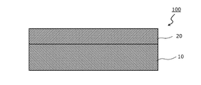
- FIG. 1 is a schematic cross-sectional view of a foaming member according to one embodiment of the present invention.
- the foaming member 100 has a resin foaming layer 10 and an adhesive layer 20 arranged on at least one side of the resin foaming layer 10.
- the resin foam layer 10 is composed of the resin foam.
- the thickness of the pressure-sensitive adhesive layer is preferably 5 ⁇ m to 300 ⁇ m, more preferably 6 ⁇ m to 200 ⁇ m, further preferably 7 ⁇ m to 100 ⁇ m, and particularly preferably 8 ⁇ m to 50 ⁇ m.
- the foamed member of the present invention can exhibit excellent shock absorption.
- the pressure-sensitive adhesive layer a layer made of any suitable pressure-sensitive adhesive can be adopted.
- the pressure-sensitive adhesive constituting the pressure-sensitive adhesive layer include rubber-based pressure-sensitive adhesives (synthetic rubber-based pressure-sensitive adhesives, natural rubber-based pressure-sensitive adhesives, etc.), urethane-based pressure-sensitive adhesives, acrylic urethane-based pressure-sensitive adhesives, acrylic-based pressure-sensitive adhesives, and silicone-based pressure-sensitive adhesives.
- examples thereof include pressure-sensitive adhesives, polyester-based pressure-sensitive adhesives, polyamide-based pressure-sensitive adhesives, epoxy-based pressure-sensitive adhesives, vinyl alkyl ether-based pressure-sensitive adhesives, fluorine-based pressure-sensitive adhesives, and rubber-based pressure-sensitive adhesives.
- the pressure-sensitive adhesive constituting the pressure-sensitive adhesive layer is preferably at least one selected from an acrylic pressure-sensitive adhesive, a silicone-based pressure-sensitive adhesive, and a rubber-based pressure-sensitive adhesive. Such an adhesive may be only one kind or two or more kinds.
- the pressure-sensitive adhesive layer may be one layer or two or more layers.
- the pressure-sensitive adhesive constituting the pressure-sensitive adhesive layer may contain any suitable other component as long as the effect of the present invention is not impaired.
- Other components include, for example, other polymer components, softeners, antioxidants, hardeners, plasticizers, fillers, antioxidants, thermal polymerization initiators, photopolymerization initiators, UV absorbers, light stabilizers.
- Colorants pigments, dyes, etc.
- solvents organic solvents
- surfactants eg, ionic surfactants, silicone-based surfactants, fluorine-based surfactants, etc.
- cross-linking agents eg, polyisocyanate-based
- Cross-linking agents silicone-based cross-linking agents, epoxy-based cross-linking agents, alkyl etherified melamine-based cross-linking agents, etc.
- the thermal polymerization initiator and the photopolymerization initiator may be included in the material for forming the polymer component.
- the foamed member of the present invention can be produced by any suitable method.
- the foamed member of the present invention is produced, for example, by laminating a resin foam layer and a pressure-sensitive adhesive layer, or by laminating a material for forming a pressure-sensitive adhesive layer and a resin foam layer and then forming a pressure-sensitive adhesive layer by a curing reaction or the like. And the method of manufacturing.
- the density (apparent density) of the resin foam was calculated as follows.
- VHX-2000 Keyence's "VHX-2000” was used to observe a predetermined area (3 mm 2 ) range at a magnification of 100 times, and the length of one bubble in the thickness direction and the length of TD were measured. -Similar measurements were made for all bubbles present within a predetermined area. The aspect ratio of the bubbles was calculated by dividing the length of the TD by the length in the thickness direction, and the same calculation was performed for all the bubbles, and the average value was taken as the "aspect ratio of the bubbles of the resin foam".
- ⁇ Bubble ratio (cell ratio)> The measurement was carried out in an environment of a temperature of 23 ° C. and a humidity of 50%. Resin foam obtained in Examples and Comparative Examples with a 100 mm x 100 mm punching blade type (two processing blades (trade name "NCA07", thickness 0.5 mm, cutting edge angle 45 °, manufactured by Nakayama Co., Ltd.)) was punched out, and the dimensions of the punched sample were measured. Further, the thickness was measured with a 1/100 dial gauge having a diameter ( ⁇ ) of 20 mm of the measurement terminal. From these values, the volumes of the resin foams obtained in Examples and Comparative Examples were calculated. Next, the weight of the resin foams obtained in Examples and Comparative Examples was measured with a precision balance having a minimum scale of 0.01 g or more. From these values, the bubble ratio (cell ratio) of the resin foams obtained in Examples and Comparative Examples was calculated.
- ⁇ Thickness of bubble wall (cell wall)> Using a razor blade, the resin foam is cut in the TD (direction orthogonal to the flow direction) and in the direction perpendicular to the main surface of the resin foam (thickness direction), and a digital microscope (commodity) is used as a measuring instrument. Using the name "VHX-500" (manufactured by Keyence Co., Ltd.), an enlarged image of the bubble part of the resin foam is captured, and the image is analyzed using the analysis software of the same measuring instrument to analyze the bubble wall (cell wall). Thickness ( ⁇ m) was determined. The number of bubbles in the captured enlarged image was about 400.
- Non-foam bending stress The resin foam is pressed for 5 minutes at a temperature of (melting point + 70 ° C.) and a pressure of 15 MPa using a vacuum press molding machine (IVM-70: Iwaki Kogyo Co., Ltd.). Got The resin molded body a was cut into a sample having a width of 6 mm and a length of 50 mm, and this sample was placed on a three-point bending tool having a distance between fulcrums of 25 mm. A pushing test (manufactured by Shimadzu Corporation, trade name "AG-Xplus”) was performed at 5 mm / min, and the load (g) when the sample was pushed 5 mm was defined as a non-foam bending stress.
- Thickness recovery rate ⁇ (thickness 0.5 seconds after decompression) / (initial thickness) ⁇ x 100
- ⁇ Shock absorption rate> A resin foam, double-sided tape (product number: No. 5603W, manufactured by Nitto Denko), and PET film (product number: diamond foil MRF75, manufactured by Mitsubishi resin) were arranged in this order on the impact force sensor to form a test body. From a height of 50 cm above the PET film, a 66 g iron ball was dropped onto the test piece, and the impact force F1 was measured. Further, the impact force F0 of the blank was measured by dropping the iron ball directly onto the impact force sensor as described above. From F1 and F0, the shock absorption rate (%) was calculated by the formula (F0-F1) / F0 ⁇ 100.
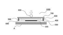
- FIG. 2 is a schematic cross-sectional view of the stress relaxation tester 1000 used for measuring the stress dispersion degree.
- a polycarbonate plate (200 mm ⁇ 300 mm ⁇ thickness 1 mm) 200 is placed on an iron support A, and a stress measurement film 300 (trade name “prescale” (trade name “prescale” (two sheets, for fine pressure (4 LW)), A sheet manufactured by FUJIFILM Corporation, which has a surface on which the pressurized portion develops color, 50 mm ⁇ 50 mm ⁇ thickness 0.16 mm) was placed.
- the obtained resin foam structure (150 mm ⁇ 200 mm ⁇ thickness 0.5 mm) 400 is placed, and a double-sided adhesive tape (No.
- the spacer 600 was arranged, and the ABS plate (200 mm ⁇ 300 mm ⁇ thickness 3 mm) 700 was placed on the uppermost part. 12 hours after the assembly, the steel ball SUS304 ( ⁇ 25 mm) 800 was placed on the center part from above, and 20N. The load of 1 min was applied. After that, the color change of the stress measurement film 300 is observed, and the one in which the color does not spread from the center of the stress measurement film 300 and is in a dot shape is C, and the one in which the color spreads from the center of the stress measurement film 300 to 25 mm is B.
- A is a film in which the color spreads widely from the center of the stress measurement film 300 to the end of 50 mm.
- Example 1 Polypropylene (melt flow rate (MFR) (230 ° C): 0.40 g / 10 min) 65 parts by weight, polyolefin-based elastomer (melt flow rate (MFR): 6 g / 10 min, JIS A hardness: 79 °) 35 parts by weight, water 80 parts by weight of magnesium oxide (trade name "KISUMA 5P” manufactured by Kyowa Chemical Industry Co., Ltd.), 10 parts by weight of carbon (trade name "Asahi # 35" manufactured by Asahi Carbon Co., Ltd.), and 1 part by weight of stearate monoglyceride It was kneaded at a temperature of 200 ° C.
- the sheet-shaped molded product was thinned using a slicer to obtain a foamed structure a1 having a thickness of 0.3 mm. Further, the resin foam a1 is passed between the rolls (the gap between the rolls) in the pair of rolls in which one roll is heated to 200 ° C. to form the resin foam A having a thickness of 0.1 mm. Obtained. The gap between the rolls was set so that the resin foam A having a thickness of 0.1 mm could be obtained. The obtained resin foam A was subjected to the above evaluation. The results are shown in Table 1.
- Example 2 Polypropylene (melt flow rate (MFR) (230 ° C): 0.40 g / 10 min) 65 parts by weight, polyolefin-based elastomer (melt flow rate (MFR): 6 g / 10 min, JIS A hardness: 79 °) 35 parts by weight, water 100 parts by weight of magnesium oxide (trade name "KISUMA 5P” manufactured by Kyowa Chemical Industry Co., Ltd.), 10 parts by weight of carbon (trade name "Asahi # 35" manufactured by Asahi Carbon Co., Ltd.), and 1 part by weight of stearate monoglyceride It was kneaded at a temperature of 200 ° C.
- the sheet-shaped molded product was thinned using a slicer to obtain a foamed structure b1 having a thickness of 0.3 mm. Further, the resin foam b1 is passed between the rolls (the gap between the rolls) in the pair of rolls in which one roll is heated to 200 ° C. to obtain the resin foam B having a thickness of 0.1 mm. Obtained. The gap between the rolls was set so that the resin foam B having a thickness of 0.1 mm could be obtained. The obtained resin foam B was subjected to the above evaluation. The results are shown in Table 1.
- the sheet-shaped molded product was thinned using a slicer to obtain a foamed structure c1 having a thickness of 0.3 mm. Further, the resin foam c1 is passed between the rolls (the gap between the rolls) in the pair of rolls in which one roll is heated to 200 ° C. to obtain the resin foam C having a thickness of 0.1 mm. Obtained. The gap between the rolls was set so that the resin foam C having a thickness of 0.1 mm could be obtained. The obtained resin foam C was subjected to the above evaluation. The results are shown in Table 1.
- the sheet-shaped molded product was thinned using a slicer to obtain a foamed structure d1 having a thickness of 0.4 mm. Further, the resin foam d1 is passed between the rolls (gap between the rolls) in the pair of rolls in which one roll is heated to 200 ° C. to form a resin foam D having a thickness of 0.1 mm. Obtained. The gap between the rolls was set so that the resin foam D having a thickness of 0.1 mm could be obtained. The obtained resin foam D was subjected to the above evaluation. The results are shown in Table 1.
- the sheet-shaped molded product was thinned using a slicer to obtain a foamed structure e1 having a thickness of 0.4 mm. Further, the resin foam e1 is passed between the rolls (gap between the rolls) in the pair of rolls in which one roll is heated to 200 ° C. to form a resin foam E having a thickness of 0.1 mm. Obtained. The gap between the rolls was set so that the resin foam E having a thickness of 0.1 mm could be obtained. The obtained resin foam E was subjected to the above evaluation. The results are shown in Table 1.
- the sheet-shaped molded product was thinned using a slicer to obtain a foamed structure f1 having a thickness of 0.3 mm. Further, the resin foam f1 is passed between the rolls (the gap between the rolls) in the pair of rolls in which one roll is heated to 200 ° C. to obtain the resin foam F having a thickness of 0.1 mm. Obtained. The gap between the rolls was set so that the resin foam F having a thickness of 0.1 mm could be obtained. The obtained resin foam F was subjected to the above evaluation. The results are shown in Table 1.
- the resin foam of the present invention is excellent in "stress dispersibility". Such a resin foam is advantageous in that it can prevent display unevenness due to pressing when applied to an image display device.
- Foam member 10 Resin foam layer 20 Adhesive layer 1000 Stress relaxation tester A Iron support 200 Polycarbonate plate 300 Stress measurement film 400 Resin foam structure 500 Double-sided adhesive tape 600 Spacer 700 ABS plate 800 Iron ball
Landscapes
- Chemical & Material Sciences (AREA)
- Organic Chemistry (AREA)
- Engineering & Computer Science (AREA)
- Materials Engineering (AREA)
- Health & Medical Sciences (AREA)
- Chemical Kinetics & Catalysis (AREA)
- Medicinal Chemistry (AREA)
- Polymers & Plastics (AREA)
- Inorganic Chemistry (AREA)
- Emergency Medicine (AREA)
- Manufacture Of Porous Articles, And Recovery And Treatment Of Waste Products (AREA)
Abstract
Description
1つの実施形態においては、上記樹脂発泡体は、50%圧縮荷重が10N/cm2~30N/cm2である。
1つの実施形態においては、上記樹脂発泡体は、圧縮弾性率が、200kPa以上である。
1つの実施形態においては、上記樹脂発泡体は、非発泡曲げ応力が、5MPa以上である。
1つの実施形態においては、上記樹脂発泡体は、繰り返し圧縮による厚み変化率が、10%以下である。
1つの実施形態においては、上記樹脂発泡体は、みかけ密度が、0.02g/cm3~0.50g/cm3である。
1つの実施形態においては、上記樹脂発泡体は、厚み回復率が、75%以上である。
1つの実施形態においては、上記樹脂発泡体が有する気泡のアスペクト比が、1.5以上である。
1つの実施形態においては、上記樹脂発泡体は、平均気泡径が10μm~200μmである。
1つの実施形態においては、上記樹脂発泡体は、気泡率が、30%以上である。
1つの実施形態においては、上記樹脂発泡体は、気泡径の変動係数が、0.5以下である。
1つの実施形態においては、上記樹脂発泡体は、気泡壁の厚みが、0.1μm~10μmである。
1つの実施形態においては、上記樹脂発泡体は、ポリオレフィン系樹脂を含む。
1つの実施形態においては、上記ポリオレフィン系樹脂が、ポリオレフィン系エラストマー以外のポリオレフィンとポリオレフィン系エラストマーの混合物である。
1つの実施形態においては、上記樹脂発泡体は、片面または両面に、熱溶融層を有する。
本発明の別の局面によれば、発泡部材が提供される。この発泡部材は、樹脂発泡層と、該樹脂発泡層の少なくとも一方の側に配置された粘着剤層を有し、該樹脂発泡層が、上記樹脂発泡体である。
本発明の樹脂発泡体は、50%圧縮荷重が5N/cm2~30N/cm2であり、6時間後の圧縮応力保持率が50%以上であり、12看護の圧縮応力保持率が50%以上である。本発明の樹脂発泡体は、気泡構造(セル構造)を有する。気泡構造(セル構造)としては、独立気泡構造、連続気泡構造、半連続半独立気泡構造(独立気泡構造と連続気泡構造が混在している気泡構造)などが挙げられる。樹脂発泡体の気泡構造は、連続気泡構造、または半連続半独立気泡構造が好ましく、半連続半独立気泡構造がより好ましい。本発明の樹脂発泡体は、樹脂組成物を発泡させることにより得られる。上記樹脂組成物は、樹脂発泡体を構成する樹脂を少なくとも含有する組成物である。
・衝撃力センサー上に、樹脂発泡体、両面テープ(品番:No.5603W、日東電工製)、PETフィルム(品番:ダイヤホイルMRF75、三菱樹脂製)をこの順に配置して試験体を形成した。PETフィルム上方50cmの高さから、66gの鉄球を試験体に落下させて、衝撃力F1を測定する。
・また、衝撃力センサーに直接、上記のように鉄球を落下させて、ブランクの衝撃力F0を測定する。
・F1、F0から、(F0-F1)/F0×100の式により、衝撃吸収率(%)を算出する。
厚み回復率(%)={(圧縮状態を解除してから0.5秒後の厚み)/(初期厚み)}×100
初期厚み:荷重を加える前の樹脂発泡体の厚み。
圧縮状態を解除してから0.5秒後の厚み:樹脂発泡体に1000g/cm2の荷重を加えた状態で120秒間維持し、圧縮を解除し、解除してから0.5秒後の樹脂発泡体の厚み。
・樹脂発泡体を、カミソリ刃を用いて、TD(流れ方向に直交する方向)、かつ、樹脂発泡体の主面に対して垂直方向(厚み方向)に切断し、所定面積(3mm2)範囲を倍率100倍で観察する。気泡一個の厚み方向の長さとTDの長さを測定する。
・同様の測定を所定面積内に存在する全ての気泡に対して行う。
・気泡のアスペクト比は、TDの長さ÷厚み方向の長さで計算され、全ての気泡で同様の計算を行い、平均した値を「樹脂発泡体が有する気泡のアスペクト比」とする。
本発明の樹脂発泡体は、代表的には、樹脂組成物を発泡させて得られ得る。樹脂組成物は、任意の適切な樹脂材料(ポリマー)を含む。
本発明の樹脂発泡体は、代表的には、樹脂組成物を発泡させて得られる。発泡の方法(気泡の形成方法)としては、物理的方法や化学的方法など、発泡成形に通常用いられる方法が採用できる。すなわち、本発明の樹脂発泡体は、代表的には、物理的方法により発泡して形成された発泡体(物理発泡体)であってもよいし、化学的方法により発泡して形成された発泡体(化学発泡体)であってもよい。物理的方法は、一般的に、空気や窒素等のガス成分をポリマー溶液に分散させて、機械的混合により気泡を形成させるもの(機械発泡体)である。化学的方法は、一般的に、ポリマーベースに添加された発泡剤の熱分解により生じたガスによりセルを形成し、発泡体を得る方法である。
本発明の樹脂発泡体を形成させる一つの実施形態1としては、例えば、エマルション樹脂組成物(樹脂材料(ポリマー)などを含むエマルション)を機械的に発泡させて起泡化させる工程(工程A)を経て樹脂発泡体を形成する形態が挙げられる。起泡装置としては、例えば、高速せん断方式の装置、振動方式の装置、加圧ガスの吐出方式の装置などが挙げられる。これらの起泡装置の中でも、気泡径の微細化、大容量作製の観点から、高速せん断方式の装置が好ましい。本発明の樹脂発泡体を形成させるこの一つの実施形態1は、どのような樹脂組成物からの形成にも適用可能である。
本発明の樹脂発泡体を形成させる一つの実施形態2としては、樹脂組成物を発泡剤により発泡させて発泡体を形成する形態が挙げられる。発泡剤としては、発泡成形に通常用いられるものを使用でき、環境保護及び被発泡体に対する低汚染性の観点から、高圧の不活性ガスを用いることが好ましい。
図1は、本発明の1つの実施形態による発泡部材の概略断面図である。発泡部材100は、樹脂発泡層10と、樹脂発泡層10の少なくとも一方の側に配置された粘着剤層20とを有する。樹脂発泡層10は、上記樹脂発泡体により構成される。
<50%圧縮荷重>
JIS K 6767に記載されている発泡体の圧縮硬さ測定方法に準じて測定した。具体的には、実施例・比較例で得られた樹脂発泡体を30mm×30mmサイズに切り出して試験片とし、圧縮速度10mm/minで圧縮率が50%となるまで圧縮したときの応力(N)を単位面積(1cm2)当たりに換算して、25%圧縮荷重(N/cm2)、50%圧縮荷重(N/cm2)、とした。
精密万能試験機(オートグラフ AG-X plus、島津製作所製)を用いて実施例・比較例で得られた樹脂発泡体を30mm×30mmサイズに切り出して試験片とし、圧縮速度10mm/minで圧縮率が50%となるまで圧縮した直後の応力(N1)とし、圧縮率が50%に到達した後に、変位を保持し、所定時間(6時間、12時間)経過後の応力(N2)とした。そして、圧縮応力保持率[%]=N2/N1×100の式により算出した。
樹脂発泡体の密度(見かけ密度)は、以下のように算出した。実施例・比較例で得られた樹脂発泡体を20mm×20mmサイズに打ち抜いて試験片とし、試験片の寸法をノギスで測定した。次に、試験片の重量を電子天秤にて測定した。そして、次式により算出した。
見かけ密度(g/cm3)=試験片の重量/試験片の体積
樹脂発泡体を、カミソリ刃を用いて、TD(流れ方向に直交する方向)、かつ、樹脂発泡体の主面に対して垂直方向(厚み方向)に切断し、計測器としてデジタルマイクロスコープ(商品名「VHX-500」、キーエンス株式会社製)を用い、樹脂発泡体の気泡部の拡大画像を取り込み、同計測器の解析ソフトを用いて、画像解析することにより、数平均気泡径(平均セル径)(μm)を求めた。なお、取り込んだ拡大画像の気泡数は400個程度であった。また、セル径の全データから標準偏差を計算し、以下の式を用いて変動係数を算出した。
変動係数=標準偏差/平均気泡径(平均セル径)
計測器としてデジタルマイクロスコープ(商品名「VHX-2000、キーエンス株式会社製)を用い、下記の方法で、実施例・比較例で得られた樹脂発泡体が有する気泡のスペクト比を測定した。
・樹脂発泡体を、カミソリ刃を用いて、TD(流れ方向に直交する方向)、かつ、樹脂発泡体の主面に対して垂直方向(厚み方向)に切断し、切断面をマイクロスコープ(例えば、キーエンス製「VHX-2000」)を用いて、所定面積(3mm2)範囲を倍率100倍で観察し、気泡一個の厚み方向の長さとTDの長さを測定した。
・同様の測定を所定面積内に存在する全ての気泡に対して行った。
・気泡のアスペクト比は、TDの長さ÷厚み方向の長さで計算され、全ての気泡で同様の計算を行い、平均した値を「樹脂発泡体が有する気泡のアスペクト比」とした。
温度23℃、湿度50%の環境下で測定を行った。100mm×100mmの打抜き刃型(2枚の加工刃(商品名「NCA07」、厚さ0.5mm、刃先角度45°、ナカヤマ社製))にて実施例・比較例で得られた樹脂発泡体を打抜き、打抜いた試料の寸法を測定した。また、測定端子の直径(φ)20mmである1/100ダイヤルゲージにて厚みを測定した。これらの値から実施例・比較例で得られた樹脂発泡体の体積を算出した。次に、実施例・比較例で得られた樹脂発泡体の重量を最小目盛り0.01g以上の上皿天秤にて測定した。これらの値より、実施例・比較例で得られた樹脂発泡体の気泡率(セル率)を算出した。
樹脂発泡体を、カミソリ刃を用いて、TD(流れ方向に直交する方向)、かつ、樹脂発泡体の主面に対して垂直方向(厚み方向)に切断し、計測器としてデジタルマイクロスコープ(商品名「VHX-500」、キーエンス株式会社製)を用いて、樹脂発泡体の気泡部の拡大画像を取り込み、同計測器の解析ソフトを用いて、画像解析することにより、気泡壁(セル壁)の厚み(μm)を求めた。なお、取り込んだ拡大画像の気泡数は400個程度であった。
樹脂発泡体を、真空プレス成型機(IVM-70:岩城工業社)を用いて、(融点+70℃)の温度、15MPaの圧力で5分間、プレスすることにより、非発泡状態の樹脂成形体aを得た。
樹脂成形体aを、幅6mm、長さ50mmに切り出してサンプルとし、このサンプルを支点間距離25mmの3点曲げ冶具の上に置き、23℃×50%RHの環境下で、押し込み速度0.5mm/minで押し込み試験(島津製作所社製、商品名「AG-Xplus」)を行い、当該サンプルを5mm押し込んだときの荷重(g)を非発泡曲げ応力とした。
JIS K 6767の圧縮試験の項に基づいて、樹脂発泡体の圧縮率(%)、圧縮反発力(kPa)を測定し、圧縮率5%の時の圧縮反発力F(5%)と圧縮率15%の時の圧縮j反発力F(15%)をそれぞれ読み取り、F(5%)、F(15%)から、(F(15%)-F(5%))/(15-5)×100の式により、圧縮弾性率を算出した。
樹脂発泡体に、樹脂発泡体に1000g/cm2の荷重を加えた状態で120秒間維持し、圧縮を解除し、解除してから0.5秒後の樹脂発泡体の厚み(圧縮状態を解除してから0.5秒後の厚み)を測定した。「圧縮状態を解除してから0.5秒後の厚み」と、荷重を加える前の樹脂発泡体の厚み(初期厚み)とから、下記の式により、厚み回復率を求めた。
厚み回復率(%)={(圧縮状態を解除してから0.5秒後の厚み)/(初期厚み)}×100
マイクロサーボ(MMT-250NV-10、島津製作所製)を用いて、先端が平坦の円盤治具(圧縮用アタッチメント円盤型圧縮治具 PC-5040、接触面積:4.9cm2、株式会社イマダ)を発泡体に50%圧縮、10%圧縮となるように繰り返し治具を変位させ、5000回繰り返し圧縮を行った(初期荷重0.15N、ダウンスピード5min/mm、アップスピード5min/mm)。試験後の厚みをデジタルマイクロスコープ(商品名「VHX-500」、キーエンス株式会社製)を用いて測定した。試験前の厚みZ0、試験後の厚みをZ1とし、(Z0-Z1)/Zo×100 の式により、繰り返し圧縮による厚み変化率を算出した。
衝撃力センサー上に、樹脂発泡体、両面テープ(品番:No.5603W、日東電工製)、PETフィルム(品番:ダイヤホイルMRF75、三菱樹脂製)をこの順に配置して試験体を形成した。PETフィルム上方50cmの高さから、66gの鉄球を試験体に落下させて、衝撃力F1を測定した。
また、衝撃力センサーに直接、上記のように鉄球を落下させて、ブランクの衝撃力F0を測定した。
F1、F0から、(F0-F1)/F0×100の式により、衝撃吸収率(%)を算出した。
図2は、応力分散度の測定に用いる応力緩和試験機1000の概略断面図である。
図2に示すように、鉄製の支持体Aにポリカーボネート板(200mm×300mm×厚み1mm)200を置き、その上に応力測定フィルム300(商品名「プレスケール」(ツーシート、微圧用(4LW)、富士フイルム株式会社製、加圧した部分が発色する面を有するシート、50mm×50mm×厚み0.16mm)を置いた。次に、応力測定フィルム300の上に測定対象の実施例・比較例で得られた樹脂発泡構造体(150mm×200mm×厚み0.5mm)400を置き、その上に両面接着テープ(No.5603、日東電工製、厚み0.03mm)500を貼り、厚み0.05mmのスペーサー600を配置させて、最上部にABS板(200mm×300mm×厚み3mm)700を置いた。組付け後、12時間後にその上から、中心部に鋼球SUS304(φ25mm)800を置き、20Nの荷重を1min加えた。
その後、応力測定フィルム300の色の変化を観察し、色が応力測定フィルム300の中心から広がらず点状になっているものをC,色が応力測定フィルム300の中心から25mmまで広がるものをB,色が応力測定フィルム300の中心から50mm端部まで大きく広がっているものをAとした。
ポリプロピレン(メルトフローレート(MFR)(230℃):0.40g/10min)65重量部、ポリオレフィン系エラストマー(メルトフローレート(MFR):6g/10min、JIS A硬度:79°)35重量部、水酸化マグネシウム(商品名「KISUMA 5P」協和化学工業製)80重量部、カーボン(商品名「旭♯35」旭カーボン株式会社製)10重量部、およびステアリン酸モノグリセリド1重量部を、日本製鋼所(JSW)社製の二軸混練機にて、200℃の温度で混練した後、ストランド状に押出し、水冷後ペレット状に成形した。このペレットを、日本製鋼所社製の単軸押出機に投入し、220℃の雰囲気下、13MPa(注入後12MPa)の圧力で、二酸化炭素ガスを注入した。二酸化炭素ガスは、樹脂100重量部に対して4.5重量部の割合で注入した。二酸化炭素ガスを十分飽和させた後、発泡に適した温度まで冷却後、ダイから押出して、シート状成形体を得た。当該シート状成形体をスライサーを用いて薄膜化し、厚みが0.3mmの発泡構造体a1を得た。
さらに、一方のロールが200℃に加熱された一対のロールにおけるロール間(ロールとロールの間の隙間)に、上記樹脂発泡体a1を通過させて、厚みが0.1mmの樹脂発泡体Aを得た。なお、ロール間のギャップ(隙間)は、厚みが0.1mmの樹脂発泡体Aが得られるように設定した。
得られた樹脂発泡体Aを上記評価に供した。結果を表1に示す。
ポリプロピレン(メルトフローレート(MFR)(230℃):0.40g/10min)65重量部、ポリオレフィン系エラストマー(メルトフローレート(MFR):6g/10min、JIS A硬度:79°)35重量部、水酸化マグネシウム(商品名「KISUMA 5P」協和化学工業製)100重量部、カーボン(商品名「旭♯35」旭カーボン株式会社製)10重量部、およびステアリン酸モノグリセリド1重量部を、日本製鋼所(JSW)社製の二軸混練機にて、200℃の温度で混練した後、ストランド状に押出し、水冷後ペレット状に成形した。このペレットを、日本製鋼所社製の単軸押出機に投入し、220℃の雰囲気下、13MPa(注入後12MPa)の圧力で、二酸化炭素ガスを注入した。二酸化炭素ガスは、樹脂100重量部に対して3.5重量部の割合で注入した。二酸化炭素ガスを十分飽和させた後、発泡に適した温度まで冷却後、ダイから押出して、シート状成形体を得た。当該シート状成形体をスライサーを用いて薄膜化し、厚みが0.3mmの発泡構造体b1を得た。
さらに、一方のロールが200℃に加熱された一対のロールにおけるロール間(ロールとロールの間の隙間)に、上記樹脂発泡体b1を通過させて、厚みが0.1mmの樹脂発泡体Bを得た。なお、ロール間のギャップ(隙間)は、厚みが0.1mmの樹脂発泡体Bが得られるように設定した。
得られた樹脂発泡体Bを上記評価に供した。結果を表1に示す。
ポリプロピレン(メルトフローレート(MFR)(230℃):0.40g/10min)65重量部、ポリオレフィン系エラストマー(メルトフローレート(MFR):6g/10min、JIS A硬度:79°)35重量部、水酸化マグネシウム(商品名「KISUMA 5P」協和化学工業製)120重量部、カーボン(商品名「旭♯35」旭カーボン株式会社製)10重量部、およびステアリン酸モノグリセリド1重量部を、日本製鋼所(JSW)社製の二軸混練機にて、200℃の温度で混練した後、ストランド状に押出し、水冷後ペレット状に成形した。このペレットを、日本製鋼所社製の単軸押出機に投入し、220℃の雰囲気下、13MPa(注入後12MPa)の圧力で、二酸化炭素ガスを注入した。二酸化炭素ガスは、樹脂100重量部に対して3.0重量部の割合で注入した。二酸化炭素ガスを十分飽和させた後、発泡に適した温度まで冷却後、ダイから押出してシート状成形体を得た。当該シート状成形体をスライサーを用いて薄膜化し、厚みが0.3mmの発泡構造体c1を得た。
さらに、一方のロールが200℃に加熱された一対のロールにおけるロール間(ロールとロールの間の隙間)に、上記樹脂発泡体c1を通過させて、厚みが0.1mmの樹脂発泡体Cを得た。なお、ロール間のギャップ(隙間)は、厚みが0.1mmの樹脂発泡体Cが得られるように設定した。
得られた樹脂発泡体Cを上記評価に供した。結果を表1に示す。
ポリプロピレン(メルトフローレート(MFR)(230℃):0.40g/10min)15重量部、ポリプロピレン(メルトフローレート(MFR)(230℃):1.1g/10min)15重量部、ポリオレフィン系エラストマー(メルトフローレート(MFR):6g/10min、JIS A硬度:79°)75重量部、水酸化マグネシウム(商品名「KISUMA 5P」協和化学工業製)80重量部、カーボン(商品名「旭♯35」旭カーボン株式会社製)10重量部、およびステアリン酸モノグリセリド1重量部を、日本製鋼所(JSW)社製の二軸混練機にて、200℃の温度で混練した後、ストランド状に押出し、水冷後ペレット状に成形した。このペレットを、日本製鋼所社製の単軸押出機に投入し、220℃の雰囲気下、13MPa(注入後12MPa)の圧力で、二酸化炭素ガスを注入した。二酸化炭素ガスは、樹脂100重量部に対して2.8重量部の割合で注入した。二酸化炭素ガスを十分飽和させた後、発泡に適した温度まで冷却後、ダイから押出して、シート状成形体を得た。当該シート状成形体をスライサーを用いて薄膜化し、厚みが0.4mmの発泡構造体d1を得た。
さらに、一方のロールが200℃に加熱された一対のロールにおけるロール間(ロールとロールの間の隙間)に、上記樹脂発泡体d1を通過させて、厚みが0.1mmの樹脂発泡体Dを得た。なお、ロール間のギャップ(隙間)は、厚みが0.1mmの樹脂発泡体Dが得られるように設定した。
得られた樹脂発泡体Dを上記評価に供した。結果を表1に示す。
ポリプロピレン(メルトフローレート(MFR)(230℃):0.40g/10min)15重量部、ポリプロピレン(メルトフローレート(MFR)(230℃):1.1g/10min)15重量部、ポリオレフィン系エラストマー(メルトフローレート(MFR):6g/10min、JIS A硬度:79°)75重量部、水酸化マグネシウム(商品名「KISUMA 5P」協和化学工業製)60重量部、カーボン(商品名「旭♯35」旭カーボン株式会社製)10重量部、およびステアリン酸モノグリセリド1重量部を、日本製鋼所(JSW)社製の二軸混練機にて、200℃の温度で混練した後、ストランド状に押出し、水冷後ペレット状に成形した。このペレットを、日本製鋼所社製の単軸押出機に投入し、220℃の雰囲気下、13MPa(注入後12MPa)の圧力で、二酸化炭素ガスを注入した。二酸化炭素ガスは、樹脂100重量部に対して2.6重量部の割合で注入した。二酸化炭素ガスを十分飽和させた後、発泡に適した温度まで冷却後、ダイから押出して、シート状成形体を得た。当該シート状成形体をスライサーを用いて薄膜化し、厚みが0.4mmの発泡構造体e1を得た。
さらに、一方のロールが200℃に加熱された一対のロールにおけるロール間(ロールとロールの間の隙間)に、上記樹脂発泡体e1を通過させて、厚みが0.1mmの樹脂発泡体Eを得た。なお、ロール間のギャップ(隙間)は、厚みが0.1mmの樹脂発泡体Eが得られるように設定した。
得られた樹脂発泡体Eを上記評価に供した。結果を表1に示す。
ポリプロピレン(メルトフローレート(MFR)(230℃):0.40g/10min)45重量部、ポリオレフィン系エラストマー(メルトフローレート(MFR):6g/10min、JIS A硬度:79°)55重量部、水酸化マグネシウム(商品名「KISUMA 5P」協和化学工業製)10重量部、カーボン(商品名「旭♯35」旭カーボン株式会社製)10重量部、およびステアリン酸モノグリセリド1重量部を、日本製鋼所(JSW)社製の二軸混練機にて、200℃の温度で混練した後、ストランド状に押出し、水冷後ペレット状に成形した。このペレットを、日本製鋼所社製の単軸押出機に投入し、220℃の雰囲気下、13MPa(注入後12MPa)の圧力で、二酸化炭素ガスを注入した。二酸化炭素ガスは、樹脂100重量部に対して5.5重量部の割合で注入した。二酸化炭素ガスを十分飽和させた後、発泡に適した温度まで冷却後、ダイから押出して、シート状成形体を得た。当該シート状成形体をスライサーを用いて薄膜化し、厚みが0.3mmの発泡構造体f1を得た。
さらに、一方のロールが200℃に加熱された一対のロールにおけるロール間(ロールとロールの間の隙間)に、上記樹脂発泡体f1を通過させて、厚みが0.1mmの樹脂発泡体Fを得た。なお、ロール間のギャップ(隙間)は、厚みが0.1mmの樹脂発泡体Fが得られるように設定した。
得られた樹脂発泡体Fを上記評価に供した。結果を表1に示す。
ポリプロピレン(メルトフローレート(MFR)(230℃):0.40g/10min)15重量部、ポリプロピレン(メルトフローレート(MFR)(230℃):1.1g/10min)15重量部、ポリオレフィン系エラストマー(メルトフローレート(MFR):6g/10min、JIS A硬度:79°)75重量部、水酸化マグネシウム(商品名「KISUMA 5P」協和化学工業製)80重量部、カーボン(商品名「旭♯35」旭カーボン株式会社製)10重量部、およびステアリン酸モノグリセリド1重量部を、日本製鋼所(JSW)社製の二軸混練機にて、200℃の温度で混練した後、ストランド状に押出し、水冷後ペレット状に成形した。このペレットを、日本製鋼所社製の単軸押出機に投入し、220℃の雰囲気下、13MPa(注入後12MPa)の圧力で、二酸化炭素ガスを注入した。二酸化炭素ガスは、樹脂100重量部に対して2.8重量部の割合で注入した。二酸化炭素ガスを十分飽和させた後、発泡に適した温度まで冷却後、ダイから押出して、シート状成形体を得た。当該シート状成形体をスライサーを用いて薄膜化し、厚みが0.1mmの樹脂発泡体Gを得た。
得られた樹脂発泡体Gを上記評価に供した。結果を表1に示す。

10 樹脂発泡層
20 粘着剤層
1000 応力緩和試験機
A 鉄製の支持体
200 ポリカーボネート板
300 応力測定フィルム
400 樹脂発泡構造体
500 両面接着テープ
600 スペーサー
700 ABS板
800 鉄球
Claims (16)
- 50%圧縮荷重が5N/cm2~30N/cm2であり、
6時間後の圧縮応力保持率が50%以上であり、
12時間後の圧縮応力保持率が50%以上であり、
気泡構造を有する、
樹脂発泡体。 - 50%圧縮荷重が10N/cm2~30N/cm2である、請求項1に記載の樹脂発泡体。
- 圧縮弾性率が、200kPa以上である、請求項1または2に記載の樹脂発泡体。
- 非発泡曲げ応力が、5MPa以上である、請求項1から3のいずれかに記載の樹脂発泡体。
- 繰り返し圧縮による厚み変化率が、10%以下である、請求項1から4のいずれかに記載の樹脂発泡体。
- みかけ密度が、0.02g/cm3~0.50g/cm3である、請求項1から5のいずれかに記載の樹脂発泡体。
- 厚み回復率が、75%以上である、請求項1から6のいずれかに記載の樹脂発泡体。
- 前記樹脂発泡体が有する気泡のアスペクト比が、1.5以上である、請求項1から7のいずれかに記載の樹脂発泡体。
- 平均気泡径が10μm~200μmである、請求項1から8のいずれかに記載の樹脂発泡体。
- 気泡率が、30%以上である、請求項1から9のいずれかに記載の樹脂発泡体。
- 気泡径の変動係数が、0.5以下である、請求項1から10のいずれかに記載の樹脂発泡体。
- 気泡壁の厚みが、0.1μm~10μmである、請求項1から11のいずれかに記載の樹脂発泡体。
- ポリオレフィン系樹脂を含む、請求項1から12のいずれかに記載の樹脂発泡体。
- 前記ポリオレフィン系樹脂が、ポリオレフィン系エラストマー以外のポリオレフィンとポリオレフィン系エラストマーの混合物である、請求項13に記載の樹脂発泡体。
- 片面または両面に、熱溶融層を有する、請求項1から14のいずれかに記載の樹脂発泡体。
- 樹脂発泡層と、該樹脂発泡層の少なくとも一方の側に配置された粘着剤層を有し、
該樹脂発泡層が、請求項1から15のいずれかに記載の樹脂発泡体である、
発泡部材。
Priority Applications (2)
| Application Number | Priority Date | Filing Date | Title |
|---|---|---|---|
| CN202080081924.2A CN114761473B (zh) | 2019-11-25 | 2020-11-25 | 树脂发泡体 |
| JP2021561445A JP7611853B2 (ja) | 2019-11-25 | 2020-11-25 | 樹脂発泡体 |
Applications Claiming Priority (2)
| Application Number | Priority Date | Filing Date | Title |
|---|---|---|---|
| JP2019212436 | 2019-11-25 | ||
| JP2019-212436 | 2019-11-25 |
Publications (1)
| Publication Number | Publication Date |
|---|---|
| WO2021106914A1 true WO2021106914A1 (ja) | 2021-06-03 |
Family
ID=76129410
Family Applications (5)
| Application Number | Title | Priority Date | Filing Date |
|---|---|---|---|
| PCT/JP2020/043762 Ceased WO2021106913A1 (ja) | 2019-11-25 | 2020-11-25 | 樹脂発泡体 |
| PCT/JP2020/043760 Ceased WO2021106911A1 (ja) | 2019-11-25 | 2020-11-25 | 樹脂発泡体 |
| PCT/JP2020/043759 Ceased WO2021106910A1 (ja) | 2019-11-25 | 2020-11-25 | 樹脂発泡体 |
| PCT/JP2020/043761 Ceased WO2021106912A1 (ja) | 2019-11-25 | 2020-11-25 | 樹脂発泡体 |
| PCT/JP2020/043763 Ceased WO2021106914A1 (ja) | 2019-11-25 | 2020-11-25 | 樹脂発泡体 |
Family Applications Before (4)
| Application Number | Title | Priority Date | Filing Date |
|---|---|---|---|
| PCT/JP2020/043762 Ceased WO2021106913A1 (ja) | 2019-11-25 | 2020-11-25 | 樹脂発泡体 |
| PCT/JP2020/043760 Ceased WO2021106911A1 (ja) | 2019-11-25 | 2020-11-25 | 樹脂発泡体 |
| PCT/JP2020/043759 Ceased WO2021106910A1 (ja) | 2019-11-25 | 2020-11-25 | 樹脂発泡体 |
| PCT/JP2020/043761 Ceased WO2021106912A1 (ja) | 2019-11-25 | 2020-11-25 | 樹脂発泡体 |
Country Status (4)
| Country | Link |
|---|---|
| JP (5) | JP7722927B2 (ja) |
| KR (1) | KR20220106752A (ja) |
| CN (5) | CN114761473B (ja) |
| WO (5) | WO2021106913A1 (ja) |
Cited By (1)
| Publication number | Priority date | Publication date | Assignee | Title |
|---|---|---|---|---|
| WO2023176984A1 (ja) * | 2022-03-18 | 2023-09-21 | 積水化学工業株式会社 | 発泡体シート及び粘着テープ |
Families Citing this family (5)
| Publication number | Priority date | Publication date | Assignee | Title |
|---|---|---|---|---|
| JP7820084B2 (ja) * | 2020-10-08 | 2026-02-25 | 日東電工株式会社 | 樹脂発泡体 |
| KR20240134894A (ko) * | 2022-01-18 | 2024-09-10 | 닛토덴코 가부시키가이샤 | 발포 부재 |
| KR20240133982A (ko) * | 2022-01-18 | 2024-09-05 | 닛토덴코 가부시키가이샤 | 발포 부재 |
| JP2024033676A (ja) * | 2022-08-31 | 2024-03-13 | 日東電工株式会社 | 両面粘着シート |
| CN120813639A (zh) * | 2023-03-03 | 2025-10-17 | 埃克森美孚技术与工程公司 | 发泡的基于丙烯的弹性体组合物,其制备方法和由其制成的产品 |
Citations (3)
| Publication number | Priority date | Publication date | Assignee | Title |
|---|---|---|---|---|
| JP2001348452A (ja) * | 2000-06-05 | 2001-12-18 | Nitto Denko Corp | ポリオレフィン系樹脂発泡体及びその製造方法 |
| WO2015146756A1 (ja) * | 2014-03-26 | 2015-10-01 | 日東電工株式会社 | 樹脂発泡体、発泡部材、及び、タッチパネル搭載機器 |
| JP2016088977A (ja) * | 2014-10-31 | 2016-05-23 | 日東電工株式会社 | 樹脂発泡体及び発泡部材 |
Family Cites Families (12)
| Publication number | Priority date | Publication date | Assignee | Title |
|---|---|---|---|---|
| US5670102A (en) | 1993-02-11 | 1997-09-23 | Minnesota Mining And Manufacturing Company | Method of making thermoplastic foamed articles using supercritical fluid |
| JP5701508B2 (ja) * | 2009-03-04 | 2015-04-15 | 日東電工株式会社 | 導電性を有する樹脂発泡体 |
| JP2010242061A (ja) * | 2009-03-19 | 2010-10-28 | Nitto Denko Corp | 難燃性樹脂発泡体及び難燃性発泡部材 |
| JP5914141B2 (ja) * | 2011-07-29 | 2016-05-11 | 日東電工株式会社 | ポリオレフィン系樹脂発泡体用樹脂組成物、ポリオレフィン系樹脂発泡体、発泡体製造方法、及び発泡シール材 |
| JP2013253241A (ja) * | 2012-05-11 | 2013-12-19 | Nitto Denko Corp | 樹脂発泡体及び発泡シール材 |
| JP6358825B2 (ja) * | 2013-04-10 | 2018-07-18 | 日東電工株式会社 | 樹脂発泡複合体 |
| JP5833213B2 (ja) | 2014-10-31 | 2015-12-16 | 日東電工株式会社 | 衝撃吸収材 |
| WO2016143684A1 (ja) * | 2015-03-06 | 2016-09-15 | 積水化成品工業株式会社 | ポリプロピレン系樹脂発泡シート、ポリプロピレン系樹脂発泡シートの製造方法及び粘着シート |
| JP6534645B2 (ja) | 2016-03-30 | 2019-06-26 | 積水化成品工業株式会社 | 緩衝材用発泡体及び緩衝材 |
| KR102261471B1 (ko) * | 2017-03-08 | 2021-06-07 | 도레이 카부시키가이샤 | 발포체 및 그 제조 방법 |
| JP6473846B1 (ja) * | 2017-08-28 | 2019-02-20 | 日東電工株式会社 | 樹脂シートおよび粘着剤層付樹脂シート |
| WO2020208946A1 (ja) * | 2019-04-10 | 2020-10-15 | 日東電工株式会社 | 難燃発泡体および発泡部材 |
-
2020
- 2020-11-25 WO PCT/JP2020/043762 patent/WO2021106913A1/ja not_active Ceased
- 2020-11-25 WO PCT/JP2020/043760 patent/WO2021106911A1/ja not_active Ceased
- 2020-11-25 WO PCT/JP2020/043759 patent/WO2021106910A1/ja not_active Ceased
- 2020-11-25 CN CN202080081924.2A patent/CN114761473B/zh active Active
- 2020-11-25 CN CN202080075112.7A patent/CN114641521B/zh active Active
- 2020-11-25 WO PCT/JP2020/043761 patent/WO2021106912A1/ja not_active Ceased
- 2020-11-25 CN CN202080075113.1A patent/CN114616278B/zh active Active
- 2020-11-25 JP JP2021561441A patent/JP7722927B2/ja active Active
- 2020-11-25 KR KR1020227017000A patent/KR20220106752A/ko not_active Withdrawn
- 2020-11-25 CN CN202080074465.5A patent/CN114585670A/zh active Pending
- 2020-11-25 WO PCT/JP2020/043763 patent/WO2021106914A1/ja not_active Ceased
- 2020-11-25 CN CN202080081928.0A patent/CN114761474B/zh active Active
- 2020-11-25 JP JP2021561444A patent/JP7611852B2/ja active Active
- 2020-11-25 JP JP2021561443A patent/JP7611851B2/ja active Active
- 2020-11-25 JP JP2021561445A patent/JP7611853B2/ja active Active
- 2020-11-25 JP JP2021561442A patent/JP7722928B2/ja active Active
Patent Citations (3)
| Publication number | Priority date | Publication date | Assignee | Title |
|---|---|---|---|---|
| JP2001348452A (ja) * | 2000-06-05 | 2001-12-18 | Nitto Denko Corp | ポリオレフィン系樹脂発泡体及びその製造方法 |
| WO2015146756A1 (ja) * | 2014-03-26 | 2015-10-01 | 日東電工株式会社 | 樹脂発泡体、発泡部材、及び、タッチパネル搭載機器 |
| JP2016088977A (ja) * | 2014-10-31 | 2016-05-23 | 日東電工株式会社 | 樹脂発泡体及び発泡部材 |
Cited By (3)
| Publication number | Priority date | Publication date | Assignee | Title |
|---|---|---|---|---|
| WO2023176984A1 (ja) * | 2022-03-18 | 2023-09-21 | 積水化学工業株式会社 | 発泡体シート及び粘着テープ |
| JPWO2023176984A1 (ja) * | 2022-03-18 | 2023-09-21 | ||
| JP7804693B2 (ja) | 2022-03-18 | 2026-01-22 | 積水化学工業株式会社 | 発泡体シート及び粘着テープ |
Also Published As
| Publication number | Publication date |
|---|---|
| JPWO2021106914A1 (ja) | 2021-06-03 |
| WO2021106910A1 (ja) | 2021-06-03 |
| WO2021106911A1 (ja) | 2021-06-03 |
| WO2021106913A1 (ja) | 2021-06-03 |
| JP7611852B2 (ja) | 2025-01-10 |
| JPWO2021106912A1 (ja) | 2021-06-03 |
| JPWO2021106911A1 (ja) | 2021-06-03 |
| JPWO2021106913A1 (ja) | 2021-06-03 |
| CN114641521B (zh) | 2024-08-02 |
| CN114641521A (zh) | 2022-06-17 |
| JP7722927B2 (ja) | 2025-08-13 |
| JP7611851B2 (ja) | 2025-01-10 |
| CN114761474B (zh) | 2025-02-18 |
| CN114585670A (zh) | 2022-06-03 |
| JP7611853B2 (ja) | 2025-01-10 |
| CN114616278B (zh) | 2025-01-14 |
| KR20220106752A (ko) | 2022-07-29 |
| WO2021106912A1 (ja) | 2021-06-03 |
| CN114761474A (zh) | 2022-07-15 |
| JP7722928B2 (ja) | 2025-08-13 |
| CN114761473A (zh) | 2022-07-15 |
| CN114761473B (zh) | 2025-02-25 |
| CN114616278A (zh) | 2022-06-10 |
| JPWO2021106910A1 (ja) | 2021-06-03 |
Similar Documents
| Publication | Publication Date | Title |
|---|---|---|
| JP7611853B2 (ja) | 樹脂発泡体 | |
| JP7712203B2 (ja) | 樹脂発泡体および発泡部材 | |
| JP7288994B2 (ja) | 樹脂発泡体 | |
| WO2022209767A1 (ja) | 樹脂発泡体 | |
| JP7820084B2 (ja) | 樹脂発泡体 | |
| WO2022210956A1 (ja) | 樹脂発泡体および発泡部材 | |
| JP2025010072A (ja) | 樹脂発泡体および発泡部材 | |
| WO2025009516A1 (ja) | 樹脂発泡体および発泡部材 | |
| KR20250169547A (ko) | 수지 발포체 및 발포 부재 | |
| CN116997600A (zh) | 树脂发泡体 | |
| JP2024152611A (ja) | 樹脂発泡体および発泡部材 | |
| JP2025084065A (ja) | 樹脂発泡体および発泡部材 | |
| WO2025110112A1 (ja) | 樹脂発泡体および発泡部材 |
Legal Events
| Date | Code | Title | Description |
|---|---|---|---|
| 121 | Ep: the epo has been informed by wipo that ep was designated in this application |
Ref document number: 20893807 Country of ref document: EP Kind code of ref document: A1 |
|
| ENP | Entry into the national phase |
Ref document number: 2021561445 Country of ref document: JP Kind code of ref document: A |
|
| NENP | Non-entry into the national phase |
Ref country code: DE |
|
| 122 | Ep: pct application non-entry in european phase |
Ref document number: 20893807 Country of ref document: EP Kind code of ref document: A1 |
|
| WWG | Wipo information: grant in national office |
Ref document number: 202080081924.2 Country of ref document: CN |