WO2021106371A1 - 媒体処理装置及び自動取引装置 - Google Patents
媒体処理装置及び自動取引装置 Download PDFInfo
- Publication number
- WO2021106371A1 WO2021106371A1 PCT/JP2020/037534 JP2020037534W WO2021106371A1 WO 2021106371 A1 WO2021106371 A1 WO 2021106371A1 JP 2020037534 W JP2020037534 W JP 2020037534W WO 2021106371 A1 WO2021106371 A1 WO 2021106371A1
- Authority
- WO
- WIPO (PCT)
- Prior art keywords
- pool guide
- press
- bill
- building
- container
- Prior art date
Links
Images


Classifications
-
- G—PHYSICS
- G07—CHECKING-DEVICES
- G07D—HANDLING OF COINS OR VALUABLE PAPERS, e.g. TESTING, SORTING BY DENOMINATIONS, COUNTING, DISPENSING, CHANGING OR DEPOSITING
- G07D11/00—Devices accepting coins; Devices accepting, dispensing, sorting or counting valuable papers
- G07D11/10—Mechanical details
- G07D11/14—Inlet or outlet ports
-
- B—PERFORMING OPERATIONS; TRANSPORTING
- B65—CONVEYING; PACKING; STORING; HANDLING THIN OR FILAMENTARY MATERIAL
- B65H—HANDLING THIN OR FILAMENTARY MATERIAL, e.g. SHEETS, WEBS, CABLES
- B65H31/00—Pile receivers
- B65H31/04—Pile receivers with movable end support arranged to recede as pile accumulates
- B65H31/06—Pile receivers with movable end support arranged to recede as pile accumulates the articles being piled on edge
-
- B—PERFORMING OPERATIONS; TRANSPORTING
- B65—CONVEYING; PACKING; STORING; HANDLING THIN OR FILAMENTARY MATERIAL
- B65H—HANDLING THIN OR FILAMENTARY MATERIAL, e.g. SHEETS, WEBS, CABLES
- B65H31/00—Pile receivers
- B65H31/26—Auxiliary devices for retaining articles in the pile
-
- B—PERFORMING OPERATIONS; TRANSPORTING
- B65—CONVEYING; PACKING; STORING; HANDLING THIN OR FILAMENTARY MATERIAL
- B65H—HANDLING THIN OR FILAMENTARY MATERIAL, e.g. SHEETS, WEBS, CABLES
- B65H83/00—Combinations of piling and depiling operations, e.g. performed simultaneously, of interest apart from the single operation of piling or depiling as such
- B65H83/02—Combinations of piling and depiling operations, e.g. performed simultaneously, of interest apart from the single operation of piling or depiling as such performed on the same pile or stack
-
- B—PERFORMING OPERATIONS; TRANSPORTING
- B65—CONVEYING; PACKING; STORING; HANDLING THIN OR FILAMENTARY MATERIAL
- B65H—HANDLING THIN OR FILAMENTARY MATERIAL, e.g. SHEETS, WEBS, CABLES
- B65H2301/00—Handling processes for sheets or webs
- B65H2301/40—Type of handling process
- B65H2301/42—Piling, depiling, handling piles
- B65H2301/421—Forming a pile
- B65H2301/4214—Forming a pile of articles on edge
- B65H2301/42142—Forming a pile of articles on edge by introducing articles from beneath
-
- B—PERFORMING OPERATIONS; TRANSPORTING
- B65—CONVEYING; PACKING; STORING; HANDLING THIN OR FILAMENTARY MATERIAL
- B65H—HANDLING THIN OR FILAMENTARY MATERIAL, e.g. SHEETS, WEBS, CABLES
- B65H2301/00—Handling processes for sheets or webs
- B65H2301/40—Type of handling process
- B65H2301/42—Piling, depiling, handling piles
- B65H2301/422—Handling piles, sets or stacks of articles
- B65H2301/4223—Pressing piles
-
- B—PERFORMING OPERATIONS; TRANSPORTING
- B65—CONVEYING; PACKING; STORING; HANDLING THIN OR FILAMENTARY MATERIAL
- B65H—HANDLING THIN OR FILAMENTARY MATERIAL, e.g. SHEETS, WEBS, CABLES
- B65H2405/00—Parts for holding the handled material
- B65H2405/20—Cassettes, holders, bins, decks, trays, supports or magazines for sheets stacked on edge
- B65H2405/21—Parts and details thereof
- B65H2405/211—Parts and details thereof bottom
-
- B—PERFORMING OPERATIONS; TRANSPORTING
- B65—CONVEYING; PACKING; STORING; HANDLING THIN OR FILAMENTARY MATERIAL
- B65H—HANDLING THIN OR FILAMENTARY MATERIAL, e.g. SHEETS, WEBS, CABLES
- B65H2511/00—Dimensions; Position; Numbers; Identification; Occurrences
- B65H2511/20—Location in space
- B65H2511/22—Distance
-
- B—PERFORMING OPERATIONS; TRANSPORTING
- B65—CONVEYING; PACKING; STORING; HANDLING THIN OR FILAMENTARY MATERIAL
- B65H—HANDLING THIN OR FILAMENTARY MATERIAL, e.g. SHEETS, WEBS, CABLES
- B65H2513/00—Dynamic entities; Timing aspects
- B65H2513/50—Timing
- B65H2513/52—Age; Duration; Life time or chronology of event
-
- B—PERFORMING OPERATIONS; TRANSPORTING
- B65—CONVEYING; PACKING; STORING; HANDLING THIN OR FILAMENTARY MATERIAL
- B65H—HANDLING THIN OR FILAMENTARY MATERIAL, e.g. SHEETS, WEBS, CABLES
- B65H2701/00—Handled material; Storage means
- B65H2701/10—Handled articles or webs
- B65H2701/19—Specific article or web
- B65H2701/1912—Banknotes, bills and cheques or the like
-
- G—PHYSICS
- G07—CHECKING-DEVICES
- G07D—HANDLING OF COINS OR VALUABLE PAPERS, e.g. TESTING, SORTING BY DENOMINATIONS, COUNTING, DISPENSING, CHANGING OR DEPOSITING
- G07D2211/00—Paper-money handling devices
Definitions
- the present invention relates to a medium processing device and an automatic teller machine, and is suitable for application to, for example, an automated teller machine (ATM) in which a paper leaf-shaped medium such as a banknote is inserted to perform a desired transaction. is there.
- ATM automated teller machine
- automatic teller machines used in financial institutions allow users to deposit cash such as banknotes and coins according to the content of transactions with users (for example, customers of financial institutions), and users.
- Various transactions such as withdrawal transactions for withdrawing cash to cash machines have come to be carried out.
- This automatic teller machine has, for example, a banknote deposit / withdrawal machine that processes banknote deposits / withdrawals. Further, this banknote deposit / withdrawal machine has, for example, a customer service unit for exchanging banknotes with and from the user.
- the bill deposit / withdrawal section has, for example, a container 200, a building press 201 provided inside the container 200, and a pool guide 202.
- the container 200 is provided with an intake port 200a for taking in the bills inserted in the container 200 on the front end side of the bottom surface, and a discharge port for discharging the bills to the container 200 on the rear end side of the bottom surface.
- 200b is provided.
- the building press 201 and the pool guide 202 are arranged so as to face each other so that the building press 201 is on the rear side and the pool guide 202 is on the front side, and each of them can move in the front-rear direction along the bottom surface of the container 200.
- this customer service unit moves the building press 201 and the pool guide 202 to the accumulation position near the discharge port 200b, and the discharge port is placed in the accumulation space formed between the building press 201 and the pool guide 202.
- Banknotes are discharged from 200b and accumulated.
- the customer service unit moves the bill press 201 and the pool guide 202 to a delivery position (a position at which the banknotes are delivered to the user) located in front of the accumulation position in a state where the banknotes are accumulated between them.
- the customer service unit moves the building press 201 and the pool guide 202 to the delivery position while widening the distance between the building press 201 and the pool guide 202 so as to be equal to or greater than the thickness of the bundle of accumulated banknotes BL. Let me. After that, the customer service department allows the user to take out the banknotes accumulated between the building press 201 and the pool guide 202.
- the present invention has been made in consideration of the above points, and an object of the present invention is to propose a medium processing device and an automated teller machine that can take out a medium more easily than before.
- a container for accommodating a medium to be delivered to a user and a building which is arranged opposite to the inside of the container and can be moved along the bottom surface of the container.
- a press and a pool guide, and a control unit for controlling the movement of the building press and the pool guide are provided, and the control unit integrates the medium in which the bill press and the pool guide are conveyed to the container, respectively. While moving the medium accumulated between the building press and the pool guide to the delivery position for delivering to the user, both the building press and the pool guide are moved.
- a first period and a second period following the first period are provided to move one of the building press and the pool guide.
- the building press and the pool guide can be moved in the direction from the accumulation position to the delivery position while maintaining the distance between the building press and the pool guide. It is possible to prevent the medium accumulated between the building press and the pool guide from being scattered inside. Further, in the second period, the distance between the building press and the pool guide can be widened, so that the medium can be easily taken out.
- FIG. 1 It is a perspective view which shows the appearance structure of the cash automatic teller machine. It is a side sectional view which shows the structure of the banknote deposit / withdrawal machine. It is a side sectional view which shows the structure of the upper unit. It is a side sectional view which shows the structure of the lower unit. It is a side sectional view which shows the structure of the customer service part. It is a perspective view which shows the connection part of a building press and a lift. It is a side sectional view which shows the integrated position of a building press and a pool guide. It is a side sectional view which shows the delivery position of a building press and a pool guide. It is a side sectional view which shows the operation of a building press and a pool guide. FIG.
- FIG. 5 is a side sectional view showing the operation of the building press and the pool guide following FIG.
- FIG. 5 is a side sectional view showing the operation of the building press and the pool guide following FIG.
- It is a side sectional view which shows the operation of a building press and a pool guide following FIG.
- It is a side sectional view which shows the operation of a building press and a pool guide following FIG.
- It is a timing chart which shows the operation of a bill press and a pool guide.
- It is a timing chart which shows the operation of a bill press and a pool guide.
- It is a side sectional view which shows the structure of the conventional customer service part.
- FIG. 1 shows the appearance of an automated teller machine 1 as an automated teller machine.
- This automatic teller machine 1 is installed in, for example, a financial institution or various commercial facilities, and conducts cash-related transactions such as deposit processing and withdrawal processing with users (for example, customers of financial institutions and commercial facilities). It is a device.
- the front side facing the user is the front side of the automated teller machine 1
- the opposite side is the rear side of the automated teller machine 1
- Lower side, left side, and right side are defined as upper side, lower side, left side, and right side of the automated teller machine 1, respectively.
- the automatic teller machine 1 has an appearance formed by a substantially box-shaped housing 2.
- the housing 2 is provided with a receiving portion 3 at a position where a user facing the front side of the housing 2 can easily insert bills or operate with a touch panel.
- the reception unit 3 is provided with a card entrance / exit 4, a deposit / withdrawal port 5, an operation display unit 6, a numeric keypad 7, a receipt issuing port 8, etc., and directly exchanges cash and passbooks with customers and provides information on transactions. Notifications and operation instructions are accepted.
- the card inlet / outlet 4 is a portion where various cards such as a cash card are inserted or ejected.
- a card processing unit (not shown) for reading the account number and the like magnetically recorded on various cards is provided on the back side of the card entrance / exit 4.
- the deposit / withdrawal port 5 is a portion where banknotes to be deposited by the customer are inserted and the banknotes to be withdrawn to the customer are discharged. Further, the deposit / withdrawal port 5 is opened or closed by driving the shutter.
- the operation display unit 6 is a touch panel in which a liquid crystal display panel that displays an operation screen and transaction details at the time of a transaction and a touch sensor that detects an input operation of the user are integrated.
- the numeric keypad 7 is a physical key that accepts inputs such as numbers "0" to "9", and is used for input operations such as a personal identification number and a transaction amount.
- the receipt issuing port 8 is a portion that issues a receipt on which transaction details and the like are printed at the end of transaction processing.
- a receipt processing unit (not shown) for printing transaction details and the like on the receipt is provided on the back side of the receipt issuing port 8.
- the main control unit 9 that controls the entire automatic teller machine 1 and a banknote deposit / withdrawal machine 10 that performs various processing related to banknotes are provided.
- the main control unit 9 is mainly composed of a CPU (Central Processing Unit) (not shown), and reads and executes a predetermined program from a ROM (Read Only Memory) or a flash memory (not shown) to perform deposit processing and withdrawal processing. Various processes such as are performed.
- the main control unit 9 has a storage unit including a RAM (RandomAccessMemory), a hard disk drive, a flash memory, and the like inside, and stores various information in this storage unit.
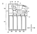
- FIG. 2 is a side sectional view of the banknote deposit / withdrawal machine 10.
- the banknote deposit / withdrawal machine 10 is roughly divided into an upper unit 10U that occupies the upper part of the whole, a lower unit 10L that occupies the lower part of the whole, and an upper unit 10U while forming an outer frame part of the whole. It is composed of a frame 10F that holds the lower unit 10L and the lower unit 10L.
- the frame 10F is mounted inside the housing 2 (FIG. 1).
- the frame 10F holds the upper unit 10U and the lower unit 10L via slide rails (not shown) extending in the front-rear direction, respectively. Therefore, the banknote deposit / withdrawal machine 10 can pull out the upper unit 10U and the lower unit 10L from the frame 10F forward (or rearward), respectively, with the front door (or rear door) of the housing 2 open. Further, the pulled-out upper unit 10U and lower unit 10L can be pushed into the frame 10F side and stored in the frame 10F.
- the upper unit 10U includes a bill control unit 20, a customer service unit 21, an upper front transport unit 22, a discrimination unit 23, and an upper rear transport unit 24, which collectively control the entire unit.
- a temporary holding unit 25 and a reject storage 26 are provided.
- the bill control unit 20 is mainly composed of a CPU (not shown), and is a process of determining a destination of bills and a process of controlling the operation of each unit by reading a predetermined program from a ROM (not shown), a flash memory, or the like and executing the program. And so on. Further, the bill control unit 20 has a storage unit including a RAM or a flash memory inside, and various information is stored in this storage unit.
- the position of the banknote control unit 20 shown in FIG. 3A is an example, and may be provided at another position.
- the customer service unit 21 is a part that allows the user to deposit banknotes and the user to withdraw banknotes by delivering the banknotes to and from the user.
- the customer service unit 21 has a container 30 for accommodating banknotes.
- the upper end of the container 30 is an opening connected to the deposit / withdrawal port 5 (FIG. 1).
- the customer service unit 21 opens or closes the opening of the container 30 by a movable shutter 31.
- the customer service unit 21 is located at the transport path 32 connecting the front end portion of the container 30 and the upper front transport unit 22 located below the front side of the customer service unit 21, and at the rear end portion of the container 30 and behind the customer service unit 21. It has a transport path 33 that connects the upper and rear transport portions 24.
- the customer service unit 21 separates the banknotes stored in the container 30 one by one and conveys them to the upper front transfer unit 22 along the transfer path 32 by the transfer rollers indicated by the circles in the figure. Further, the customer service unit 21 conveys the banknotes conveyed from the upper-rear transfer unit 24 to the container 30 along the transfer path 33 by the transfer roller and discharges the banknotes into the container 30.
- the upper front transport unit 22 is located on the front lower side inside the upper unit 10U, and switches between a transport path 40 having one branch point and a banknote transport path provided at the branch point of the transport path 40. It has a vessel 41.
- the transport path 40 is connected to the transport path 32 of the customer service unit 21, the discrimination unit 23, and the front portion of the lower unit 10L.
- the upper front transport unit 22 operates the switch 41 according to the control of the bill control unit 20 to discriminate the bill transport route formed based on the transport path 40 from the transport path 32 of the customer service unit 21.
- the transfer path is switched to the transfer path connecting the 23 or the transfer path connecting the discrimination unit 23 and the front part of the lower unit 10L. Then, the upper front transport unit 22 transports the banknotes by the transport rollers along the switched transport path.
- the discrimination unit 23 is located below the customer service unit 21 and behind the upper front transport unit 22.
- the discrimination unit 23 has a linear transport path 50 connected to the front upper front transport section 22 and the rear upper rear transport section 24, and a plurality of sensors are arranged along the transport path 50. There is.
- the discrimination unit 23 transports banknotes by a transport roller along the transport path 50, and based on the detection results obtained from a plurality of sensors, the denomination, authenticity, and correctness (whether or not the banknotes are damaged) of the banknotes. ) And the like, the transport state is recognized, and these are sent to the bill control unit 20 as a discrimination result.
- the upper and rear transport unit 24 is located behind the customer service unit 21 and the discrimination unit 23.
- the upper / rear transport unit 24 has a transport path 60 having three branch points and switches 61, 62, and 63 provided at each of the three branch points.
- the transport path 60 is connected to the transport path 33 of the customer service unit 21, the discrimination unit 23, the temporary hold unit 25, the reject storage 26, and the rear portion of the lower unit 10L.
- the upper-rear transport unit 24 operates the three switches 61, 62, and 63 according to the control of the bill control unit 20, so that the transport route of the bill formed based on the transport path 60 is set with the discriminating unit 23.
- the temporary holding unit 25 is, for example, a tape type, and the banknotes conveyed from the upper and rear conveying units 24 are wound around the peripheral side surface of the drum together with the tape and stored. Further, when the banknotes are fed out, the temporary holding unit 25 peels off the banknotes together with the tape from the peripheral side surface of the drum and delivers the banknotes to the upper / rear transport unit 24.
- the reject storage 26 is a portion for storing rejected banknotes that are judged to be severely damaged and should not be withdrawn.
- the rejected banknotes are transported from the upper / rear transport unit 24, the rejected banknotes are stored inside. Discharge and store in the storage space of.
- FIG. 3B which is an enlarged view of the lower part of FIG. 2, a lower transport portion 27 is arranged at the upper end portion of the lower unit 10L, and a lower frame 28 is provided below the lower transport portion 27.
- the lower frame 28 has a hollow rectangular parallelepiped shape with an open upper end, and four banknote storages 29 (29A, 29B, 29C, 29D) for storing reusable (recyclable) banknotes are placed in the front-rear direction. They are arranged side by side.
- the banknote storages 29 (29A to 29D) are all configured in the same manner, and have a rectangular parallelepiped shape that is long in the vertical direction.
- Each banknote storage 29 can store and pay out banknotes, and at the time of storing banknotes, the banknotes transported by the lower transport unit 27 are discharged and accumulated in the internal storage space. Further, each banknote storage 29 separates the banknotes accumulated in the internal storage space one by one from the top, transports them upward, and delivers them to the lower transport unit 27 when the banknotes are fed out. ..
- Each banknote storage 29 has a preset denomination of banknotes to be stored.
- the lower transport unit 27 has a transport path 70 having four branch points and switches 71, 72, 73, and 74 provided at each of the four branch points.
- the transport path 70 is connected to the upper front transport unit 22, the upper rear transport unit 24, and the banknote storages 29A, 29B, 29C, and 29D.
- the lower transport unit 27 operates the four switchers 71, 72, 73, and 74 according to the control of the bill control unit 20, so that the lower transport unit 27 transports the bills formed based on the transport path 70 in the upper front. It is switched to a transport path connecting the section 22 and any of the banknote storages 29A to 29D, or a transport path connecting the upper front transport section 22 and the upper rear transport section 24. Then, the lower transport unit 27 transports the banknotes by the transport rollers along the switched transport route.
- the lower frame 28 has a plurality of banknote storages 29 and the user serves a customer service unit.
- a forgotten storage for storing bills forgotten from 21 may be provided.
- the banknote deposit / withdrawal machine 10 performs a deposit counting process of counting the number of banknotes while discriminating the denomination of the banknotes deposited by the user, and then transports and stores each banknote to an appropriate storage location. It is designed to perform deposit storage processing.
- the deposit counting process and the deposit storage process are processes performed by the bill control unit 20 by controlling each unit.
- the banknote deposit / withdrawal machine 10 starts the deposit counting process when it receives an operation instruction from the user to start the deposit transaction via the operation display unit 6 (FIG. 1).
- the bill deposit / withdrawal machine 10 opens the shutter 31 (FIG. 3A) of the customer service unit 21.
- the banknote deposit / withdrawal machine 10 closes the shutter 31 of the customer service unit 21 and separates the banknotes in the container 30 one by one. It is transported to the discrimination unit 23 via the transport unit 22.
- the banknote deposit / withdrawal machine 10 transports and stores the banknotes determined as normal banknotes from the discrimination result of the discrimination unit 23 from the discrimination unit 23 to the temporary holding unit 25 via the upper / rear transport unit 24.
- banknotes that are determined as deposit rejected banknotes that are not suitable for deposit from the discrimination result of the discrimination unit 23 are transported from the discrimination unit 23 to the transport path 33 of the customer service section 21 via the upper and rear transport sections 24, and are transported through the transport path. Evacuate to 33.
- the banknote deposit / withdrawal machine 10 returns the banknotes (that is, the deposit rejected banknotes) retracted on the transport path 33 to the container 30 and opens the shutter 31. It will be returned to the user.
- the banknote deposit / withdrawal machine 10 completes the deposit counting process. After that, the banknote deposit / withdrawal machine 10 calculates the deposit amount based on the total result of the denomination and the number of banknotes taken in from the customer service unit 21, and displays a predetermined operation instruction screen on the operation display unit 6 (FIG. 1). Let the user present the deposit amount and select whether or not to continue the deposit transaction.
- the banknote deposit / withdrawal machine 10 accommodates all the banknotes stored in the temporary holding unit 25 in the customer service unit 21 via the upper / rear transport unit 24. Return to the vessel 30 and return it to the user by opening the shutter 31 (FIG. 3A).
- the banknote deposit / withdrawal machine 10 starts the deposit storage process.
- the banknote deposit / withdrawal machine 10 sequentially feeds out the banknotes (that is, normal banknotes) stored in the temporary holding unit 25 and conveys them to the discrimination unit 23 via the upper / rear transfer unit 24 to denominate the denomination. To determine.
- the banknote deposit / withdrawal machine 10 conveys the banknotes whose denomination has been determined from the discrimination unit 23 to the banknote storage 29 corresponding to the denomination via the upper front transfer unit 22 and the lower transfer unit 27 in order. Store. When all the banknotes stored in the temporary holding unit 25 have been stored, the banknote deposit / withdrawal machine 10 ends the deposit / storage process. The operation at the time of deposit transaction by the bill deposit / withdrawal machine 10 is as described above.
- the banknote deposit / withdrawal machine 10 is configured to perform a withdrawal process of withdrawing a denomination and a number of banknotes according to the amount specified by the user. This withdrawal process is also a process performed by the bill control unit 20 by controlling each unit.
- the bill deposit / withdrawal machine 10 when the bill deposit / withdrawal machine 10 receives an operation instruction from the user to start the withdrawal transaction and to specify the withdrawal amount via the operation display unit 6 (FIG. 1), the bill deposit / withdrawal machine 10 performs the withdrawal process. Start. When the withdrawal process is started, the banknote deposit / withdrawal machine 10 determines the denomination and the number of banknotes according to the withdrawal amount. Then, the bill deposit / withdrawal machine 10 pays out one bill from each bill storage 29 according to the determined denomination and the number of bills, and sequentially passes through the lower transport unit 27 and the upper front transport unit 22 to the discrimination unit 23. Transport.
- the banknote deposit / withdrawal machine 10 conveys the banknotes determined as normal banknotes from the discrimination result of the discrimination unit 23 from the discrimination unit 23 to the customer service unit 21 via the upper / rear transport unit 24 and inside the container 30. Accumulate in.
- banknotes that are determined as withdrawal reject banknotes that are not suitable for withdrawal from the discrimination result of the discrimination unit 23 are transported from the discrimination unit 23 to the reject storage 26 via the upper and rear transfer units 24 and stored. Then, when the withdrawal amount of banknotes is accumulated in the container 30, the banknote deposit / withdrawal machine 10 opens the shutter 31 of the customer service unit 21 to take out the banknotes accumulated in the container 30 to the user. Let me. The operation of the banknote deposit / withdrawal machine 10 at the time of withdrawal transaction is as described above.
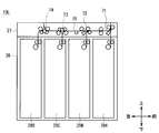
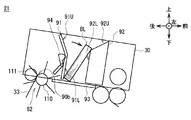
- FIG. 4 is a side sectional view of the customer service unit 21, in which a part of the transport roller and the like is omitted.
- the customer service unit 21 has a configuration in which a container 30, a separation and feeding mechanism 81, an integration mechanism 82, a transport path 32, and a transport path 33 are provided inside the housing 80.
- the container 30 is box-shaped, and the upper end is an opening connected to the deposit / withdrawal port 5 (FIG. 1), and this opening is opened or closed by the shutter 31. Further, the container 30 is provided in the housing 80 in a state of being tilted forward so that the front end side is located below the rear end side.
- the container 30 is provided with a lower frame 90, a side guide (not shown), a bill press 91, and a pool guide 92.
- the lower frame 90 is a frame forming the bottom surface of the container 30, and is tilted forward so that the front end side is located below the rear end side. That is, the bottom surface of the container 30 is tilted forward so that the front end side is located below the rear end side.
- An intake port 90a for taking in banknotes housed in the container 30 from the container 30 is provided on the front end side of the lower frame 90, and the container 30 is provided on the rear end side of the lower frame 90.
- a discharge port 90b for discharging bills inward is provided.
- the container 30 accommodates rectangular bills in a direction in which the longitudinal direction is the left-right direction, the lateral direction is the vertical direction, and the thickness direction is the front-rear direction.
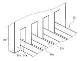
- a lift 93 that can move in the direction of rising from the lower frame 90 (upward) and in the opposite direction (downward) while being substantially parallel to the upper surface of the lower frame 90 is provided. It is provided. As will be described in detail later, the lift 93 moves the banknotes contained in the container 30 upward (that is, to the deposit / withdrawal port 5) by moving a predetermined amount in the direction of rising (upward) from the upper surface of the lower frame 90. It is designed to push up in the approaching direction).
- the upper end of the lift 93 is formed in a so-called comb-teeth shape in which elongated concave portions 93a and convex portions 93b are alternately arranged in the front-rear direction in the front-rear direction, as shown in the deformed perspective view in FIG. 5, for example. ing.
- the bill press 91 and the pool guide 92 are arranged in a positional relationship in which the bill press 91 is on the rear end side of the lower frame 90 and the pool guide 92 is on the front end side of the lower frame 90 inside the container 30. They are arranged facing each other in the direction. Inside the container 30, bills are collected in a collection space Sp formed by a lower frame 90, a building press 91, a pool guide 92, and side guides (not shown) provided on both left and right sides of the container 30. It is designed to do.
- the building press 91 is an abbreviation-shaped member when viewed from the side.
- the portion below the bent portion on the front surface facing the pool guide 92 (approximately the lower half of the front surface) is a lower flat surface 91L substantially perpendicular to the bottom surface of the container 30.
- the portion above the bent portion (approximately the upper half of the front surface) is the upper flat surface 91U extending from the upper end of the lower flat surface 91L to the rear slick.
- This building press 91 is configured to be movable in the front-rear direction along the bottom surface of the container 30. Further, the bill press 91 is configured to be rotatable in the clockwise direction in the drawing and the counterclockwise direction in the drawing via a rotation axis extending in the left-right direction (not shown). From the state of being substantially perpendicular to the bottom surface of the container 30, by rotating in the clockwise direction in the drawing, the upper plane 91U is changed to the state of being substantially perpendicular to the bottom surface of the container 30 (for example, the state shown in FIG. 6). Can be transitioned to.
- the bill press 91 has a lower end portion formed in a so-called comb-teeth shape in which concave portions 91a and convex portions 91b are alternately arranged in the left-right direction, and meshes with the upper end portion of the lift 93. It has become like. As a result, even if the bill press 91 is located upward, the lift 93 moves upward within a range until, for example, the convex portion 93b on the lift 93 side reaches the upper end of the concave portion 91a on the bill press 91 side. be able to.
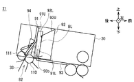
- the building press 91 is provided with a lever 94.
- the lever 94 is an abbreviated member in which a part of the lever 94 is bent in a side view.
- a protrusion 94a is provided on the upper end portion of the front surface, and the lower end portion of the front surface abuts on the lift 93. It has become.
- This lever 94 is provided on the back side (rear side) of the lower flat surface 91L of the bill press 91, and is provided in the clockwise direction in the drawing and in the drawing via the rotation shaft 94c extending in the left-right direction by the bill press 91. It is held so that it can rotate counterclockwise.
- the lever 94 is urged by a torsion spring (not shown) provided on the rotating shaft 94c so as to maintain the retracted state (for example, the state shown in FIG. 4) in which the entire lever 94 is retracted to the back side of the building press 91.
- the lever 94 rotates clockwise in the drawing, so that the lower flat surface 91L of the building press 91 is released from the retracted state. It is possible to transition to a protruding state (for example, the state shown in FIG. 7) in which only the protruding portion 94a protrudes forward from a hole (not shown) provided in the vicinity of the bent portion of the above.
- the pool guide 92 is a member having a substantially trapezoidal shape when viewed from the side.
- the rear surface facing the building press 91 is bent in a dogleg shape in a side view, and the portion below the bent portion of the rear surface (about the lower two-thirds of the front surface) is a container.
- the lower plane 92L is substantially perpendicular to the bottom surface of 30, and the portion above the bent portion of the rear surface (about the upper 1/3 of the front surface) extends upward from the upper end of the lower plane 92L to the front lick.
- the plane is 92U.
- the pool guide 92 is configured to be movable in the front-rear direction along the bottom surface of the container 30 independently of the building press 91.
- the pool guide 92 also has a lower end portion formed in a so-called comb-teeth shape in which concave portions and convex portions are alternately arranged in the left-right direction, similarly to the bill press 91. It is designed to mesh with the upper end.
- the convex portion 93b on the lift 93 side is the upper end of the concave portion 91a on the building press 91 side (or the concave portion on the pool guide 92 side). It can move upwards until it reaches the upper end of the pool.
- the separation feeding mechanism 81 has a feed roller 100, a gate roller 101, and a pickup roller 102.
- the feed roller 100 and the gate roller 101 are provided near the bottom surface of the front end of the container 30, and are arranged so as to face each other in the front-rear direction with the feed roller 100 on the front side and the gate roller 101 on the rear side with the intake port 90a interposed therebetween. Has been done.
- the pickup roller 102 is provided at the front end inside the container 30 and above the feed roller 100. When the pool guide 92 moves to the vicinity of the intake port 90a, the pickup roller 102 projects from a hole (not shown) provided in the lower plane 92L of the pool guide 92.
- the pickup roller 102 rotates clockwise in the drawing to come into contact with the banknote located on the frontmost side of the banknotes housed between the bill press 91 and the pool guide 92. , The bill is sent out to the intake port 90a.
- the feed roller 100 and the gate roller 101 rotate only the feed roller 100 without rotating the gate roller 101, so that the banknotes sent out by the pickup roller 102 are separated one by one from the intake port 90a. It is designed to go out to 32.
- the integration mechanism 82 has an integration roller 110 and a pressure roller 111.
- the accumulation roller 110 and the pressure roller 111 are provided near the bottom surface of the rear end of the container 30, and are arranged so as to face each other in the front-rear direction with the accumulation roller 110 on the front side and the pressure roller 111 on the rear side with the discharge port 90b interposed therebetween. Has been done.
- the accumulating roller 110 is rotated in the clockwise direction in the drawing, while the pressure roller 111 is rotated in the counterclockwise direction in the drawing, so that the accumulating roller 110 is conveyed to the container 30 along the conveying path 33.
- the bills are discharged from the discharge port 90b between the bill press 91 located in the vicinity of the discharge port 90b and the pool guide 92 and accumulated.
- the structure of the customer service unit 21 is as described above.
- the customer service unit 21 collects banknotes (for example, banknotes to be withdrawn) transported along the transport path 33 in the accumulation space Sp between the building press 91 and the pool guide 92, so that the building press 91 and the pool guide 21 can collect the banknotes.
- Position 92 in the stacking position is the banknotes (for example, banknotes to be withdrawn) transported along the transport path 33 in the accumulation space Sp between the building press 91 and the pool guide 92, so that the building press 91 and the pool guide 21 can collect the banknotes.
- the customer service unit 21 moves the building press 91 and the pool guide 92 to the vicinity of the discharge port 90b, and rotates the building press 91 so that the upper flat surface 91U is substantially perpendicular to the bottom surface of the container 30.
- each of the building press 91 and the pool guide 92 is positioned at the accumulation position.
- the upper plane 91U is substantially parallel to the lower plane 92L of the pool guide 92, and the lower plane 91L is tilted rearward with respect to the lower plane 92L of the pool guide 92.
- the upper flat surface 91U is located in front of the discharge port 90b, and the lower flat surface 91L is located between the lower end of the upper flat surface 91U and the discharge port 90b. That is, the lower plane 91L of the bill press 91 functions as a guide for guiding the bill BL discharged from the discharge port 90b between the upper plane 91U of the bill press 91 and the lower plane 92L of the pool guide 92.
- the pool guide 92 is in a state where the upper flat surface 92U is brought close to the upper flat surface 91U of the building press 91.
- the customer service unit 21 drives the stacking mechanism 82 to discharge the bill BL from the discharge port 90b into the stacking space Sp between the bill press 91 and the pool guide 92, and the upper side of the bill press 91.
- the flat surface 91U and the upper flat surface 92U of the pool guide 92 are accumulated so as to overlap each other in the front-rear direction.
- the customer service unit 21 gradually moves the pool guide 92 in the direction away from the building press 91 as the number of bills BL to be accumulated increases.
- the customer service unit 21 positions the bill press 91 and the pool guide 92 in the delivery position in order to deliver the banknotes (for example, banknotes to be withdrawn) accumulated in the accumulation space Sp between the building press 91 and the pool guide 92 to the user. Let me.
- the customer service unit 21 has the bill press 91 in a state where the bills BL are accumulated in the accumulation space Sp between the building press 91 and the pool guide 92, and the lower plane 91L is substantially perpendicular to the bottom surface of the container 30.
- the bill press 91 and the pool guide 92 By rotating the bill press 91 and the pool guide 92 so as to be approximately in the center between the intake port 90a and the discharge port 90b, each of the bill press 91 and the pool guide 92 is placed in the delivery position. Position it.
- the lower plane 91L is substantially parallel to the lower plane 92L of the pool guide 92
- the upper plane 91U is tilted rearward with respect to the lower plane 92L of the pool guide 92.
- the distance between the lower plane 92L of the pool guide 92 and the lower plane 91L of the building press 91 is larger than the thickness of the bundle of banknotes BL accumulated in the accumulation space Sp. It is in a state away from the bill press 91.
- the customer service unit 21 moves the lift 93 upward by a predetermined amount to push upward a bundle of banknotes BL accumulated in the accumulation space Sp between the building press 91 and the pool guide 92, and at the same time.
- the lever 94 is rotated from the retracted state to the protruding state.
- a bill stuck to the bill press 91 due to static electricity or the like can be peeled off from the bill press 91.
- the customer service unit 21 opens the shutter 31 and delivers the banknotes to the user from the deposit / withdrawal port 5.
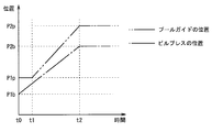
- FIG. 13A the horizontal axis indicates time
- the vertical axis indicates the position of the lower end of the front surface of the bill press 91
- the vertical axis indicates the position of the lower end of the rear surface of the pool guide 92.
- the position shown on the vertical axis of FIG. 13A is specifically the distance from the rear surface of the container 30.
- the operation of the bill press 91 and the pool guide 92 shown below is an operation controlled by the bill control unit 20.
- FIG. 8 shows the building press 91 and the pool guide 92 at t0 (see FIG. 13A) when the accumulation of a plurality of banknotes BL is completed at the accumulation position.
- a bundle of banknotes BL is accumulated between the upper flat surface 91U of the building press 91 and the lower flat surface 92L of the pool guide 92.
- t0 that is, in the integrated position
- the position of the lower end of the front surface of the building press 91 is P1b
- the position of the lower end of the rear surface of the pool guide 92 is P2b (see FIG. 13A).
- the customer service unit 21 attaches the bill press 91 to the bottom surface of the container 30 between the time point t0 and the time point t1 as shown in FIG. Rotate in the counterclockwise direction in the figure so as to be substantially vertical (that is, substantially parallel to the lower plane 92L of the pool guide 92). At this time, the lower end of the front surface of the building press 91 approaches the lower end of the rear surface of the pool guide 92, so that a bundle of banknotes BL is sandwiched between the lower flat surface 91L and the lower flat surface 92L of the pool guide 92. Become.
- the customer service unit 21 maintained the distance between the bill press 91 and the pool guide 92 (that is, the distance equal to the thickness of the bundle of accumulated banknotes BL).
- the bill press 91 and the pool guide 92 are moved in the direction (forward) toward the delivery position at almost the same speed.
- the customer service unit 21 stops the building press 91 at t2 when the building press 91 reaches the delivery position.
- the position of the lower end of the front surface of the building press 91 at t2 is P2b.
- the delivery position set for each of the building press 91 and the pool guide 92 while maintaining the distance between the building press 91 and the pool guide 92 during the period from the time point t1 to the time point t2.
- the customer service unit 21 continues to move the pool guide 92 forward as it is even after the time t2 when the building press 91 is stopped, and the pool guide 92 at the time t3 when the pool guide 92 reaches the delivery position. Stop 92. At this point, the position of the lower end of the rear surface of the pool guide 92 at t3 is P2p.
- the customer service unit 21 further moves the pool guide 92 by a predetermined amount during the period from the time point t2 to the time point t3 to move it to the delivery position.
- the distance between the bill press 91 and the pool guide 92 is wider than when both the bill press 91 and the pool guide 92 are moved while maintaining the same distance as the thickness of the bundle of accumulated banknotes BL. It has become like.
- the customer service unit 21 makes the distance between the building press 91 and the pool guide 92 larger than the thickness of the bundle of banknotes BL that are accumulated. It can be made larger, and it is possible to easily take out a bundle of banknotes BL from between the bill press 91 and the pool guide 92.
- each of the bills BL accumulated between the bill press 91 and the pool guide 92 is a virtual line extending in the direction of gravity from the center of gravity of the bill BL because the entire container 30 is tilted forward.
- the intersection Px between the banknote BL and the bottom surface of the container 30 is located in front of the contact portion between the lower end of the bill BL and the bottom surface of the container 30 (that is, the pool guide 92 side).
- each of the bills BL accumulated between the bill press 91 and the pool guide 92 leaves the lower end portion on the bill press 91 side when the pool guide 92 is separated forward. As it is, the upper end of the pool guide 92 falls toward the pool guide 92 side, and the upper end of the pool guide 92 falls in front of the pool guide 92. By doing so, even if the pool guide 92 is separated from the building press 91 and the distance between them is widened, the customer service unit 21 can disperse the bundle of banknotes BL accumulated between the building press 91 and the pool guide 92. It is possible to prevent the above and make it easier to take out a bundle of banknotes BL.
- the bill BL falls on the pool guide 92 after the pool guide 92 reaches the delivery position, but in reality, the pool guide 92 is a building. In the process of moving away from the press 91, the bill BL gradually falls toward the pool guide 92. Further, at this time, if the distance between the bill press 91 located at the delivery position and the pool guide 92 is too large, the bill BL falls down to the lower frame 90, and it becomes difficult to take out the bill BL. Therefore, the moving distance of the pool guide 92 between the time point t2 and the time point t3 is shorter than that of the bill BL in the lateral direction.
- the customer service unit 21 can tilt the bill BL accumulated between the building press 91 and the pool guide 92 toward the pool guide 92 side, so that the distance between the building press 91 and the pool guide 92 is set. Even if the bills are expanded, it is possible to prevent the bills accumulated between the bill press 91 and the pool guide 92 from falling apart.
- the customer service unit 21 moves the building press 91 and the pool guide 92 from the accumulation position to the delivery position.
- the customer service unit 21 is in a state of falling on the front surface of the pool guide 92 by raising the lift 93 arranged below the building press 91 in the delivery position and the pool guide 92.
- the bundle of banknotes BL is brought closer to the deposit / withdrawal port 5 so that the user can easily take it out.
- the customer service unit 21 rotates the lever 94 from the retracted state to the protruding state as the lift 93 rises, so that, for example, the bill BL stuck to the building press 91 due to static electricity or the like is removed. It is designed to be easily taken out by peeling it off from the bill press 91.
- the bill deposit / withdrawal machine 10 moves both the bill press 91 and the pool guide 92 while the bill control unit 20 moves the bill press 91 and the pool guide 92 from the accumulation position to the delivery position.
- a period from the time point t1 to the time point t2 to be moved (this is referred to as the first period) and a period from the time point t2 to the time point t3 to move only the pool guide 92 (this is referred to as the second period) are provided. I did.
- the banknote deposit / withdrawal machine 10 shifts the bill press 91 and the pool guide 92 from the accumulation position to the delivery position while maintaining the distance between the bill press 91 and the pool guide 92 in the first period. Since it can be moved in the direction toward the direction, it is possible to prevent the bills accumulated between the bill press 91 and the pool guide 92 from being scattered during the movement. Further, in the second period, the distance between the bill press 91 and the pool guide 92 can be widened, so that the bills can be easily taken out.
- the customer service unit 21 is provided with a lift 93 that pushes up the bills accumulated between the bill press 91 located at the delivery position and the pool guide 92 in a direction closer to the deposit / withdrawal port 5. ..
- the banknote deposit / withdrawal machine 10 can make it easier to take out banknotes.
- the bills attached to the bill press 91 are attached to the customer service unit 21 by protruding from the front surface (one side of the pool guide 92 side) of the bill press 91 in conjunction with the operation of the lift 93.
- a lever 94 to be peeled off from the bill press 91 is provided.
- the pool guide 92 is not further moved to the delivery position, but the bill press 91 is used.
- the bill press 91 and the pool guide 92 are moved to the delivery position while gradually increasing the distance between the pool guide 92 and the pool guide 92 will be briefly described.
- the banknote deposit / withdrawal machine 10 rotates the bill press 91 from the time point t0 to the time point t1 when the accumulation of a plurality of banknotes BL is completed at the accumulation position.
- the operation at this time is the same as the operation shown in FIG. 13A.
- the building press 91 and the pool guide 92 move while gradually widening the interval, and at the time point t2, each reaches the delivery position and stops.
- the distance between the bill press 91 and the pool guide 92 gradually widens, so that the bill press 91 and the pool guide 92 are accumulated between the bill press 91 and the pool guide 92.
- the bills may fall apart (see FIG. 14).
- the lever 94 must be provided with a protrusion 94x having a larger protrusion amount from the bill press 91 than the protrusion 94a, and the protrusion 94x holds a bill. It may get in the way when you take it out.
- the bill deposit / withdrawal machine 10 of the present embodiment after the bill press 91 is stopped at the delivery position, the bill is naturally separated from the pool guide 92 by separating the pool guide 92 from the bill press 91. I tried to fall to the front.
- the lever 94 may be provided with a protrusion 94a having a minimum amount of protrusion required for peeling the bill from the bill press 91, and the bill may be taken out. Sometimes the protrusion 94a does not get in the way and the bill can be easily taken out.
- the building press 91 and the pool guide 92 are moved in the direction toward the delivery position (forward), and when the building press 91 reaches the delivery position, the building press 91 is stopped, and then, for example, the building.
- the pool guide 92 may be moved forward to reach the delivery position while the press 91 is slightly returned to the rear.
- the building press 91 when the building press 91 reaches the delivery position in the first period, the building press 91 is stopped, and then, in the second period, only the pool guide 92 is moved away from the building press 91 (in the second period). It was moved to the front) by a predetermined amount to reach the delivery position.
- the amount of movement of the pool guide 92 after the building press 91 is stopped may be a preset constant amount, or banknotes accumulated between the building press 91 and the pool guide 92. It may be changed according to the number of sheets.
- the contact portion 94b of the lever 94 provided on the building press 91 is pushed up by the lift 93, so that the lever 94 rotates and transitions from the retracted state to the protruding state.
- the lever 94 and the lift 93 may be connected by another link mechanism so that the lever 94 rotates as the lift 93 rises.
- the present invention is not limited to this, and the lever 94 may be rotated independently of the lift 93 by, for example, a driving force of a motor.
- the present invention is applied to the banknote deposit / withdrawal machine 10 as a medium processing device, but the present invention is not limited to this, and for example, media other than banknotes such as money tickets, gift certificates, tickets, and forms can be used. It may be applied to the medium processing apparatus to be processed. Further, in each of the above-described embodiments, the present invention is applied to the automated teller machine 1 as an automated teller machine, but the present invention is not limited to this, and for example, media other than banknotes such as cash vouchers, gift certificates, tickets, and forms can be used. It may be applied to the automated teller machine to be handled.
- the present invention is applied to the banknote deposit / withdrawal machine 10 and the automated teller machine 1 corresponding to both the deposit transaction and the withdrawal transaction, but the present invention is not limited to this, and only the withdrawal transaction is supported. It may be applied to a medium processing device and an automated teller machine.
- the banknote control unit 20 is provided as a specific example of the control unit that controls the operations of the bill press 91, the pool guide 92, the lift 93, and the lever 94 in the banknote deposit / withdrawal machine 10. Not limited to this, for example, a control unit for controlling these may be provided in the customer service unit 21.
- the present invention is not limited to the above-described embodiments and other embodiments. That is, the scope of the present invention extends to an embodiment in which each of the above-described embodiments and a part or all of the above-mentioned other embodiments are arbitrarily combined, and an embodiment in which a part is extracted. Is.
- the present invention includes a building press and a pool guide, and can be used in various devices for accumulating media between them.
Landscapes
- Engineering & Computer Science (AREA)
- Mechanical Engineering (AREA)
- Physics & Mathematics (AREA)
- General Physics & Mathematics (AREA)
- Pile Receivers (AREA)
Abstract
【課題】従来と比べて媒体を取り出し易くする。 【解決手段】紙幣制御部20がビルプレス91とプールガイド92とを集積ポジションから引き渡しポジションへと移動させる間に、ビルプレス91とプールガイド92の両方を移動させる時点t1から時点t2までの期間と、プールガイド92のみを移動させる時点t2から時点t3までの期間とを設けるようにした。
Description
本発明は媒体処理装置及び自動取引装置に関し、例えば紙幣のような紙葉状の媒体を投入して所望の取引を行う現金自動預払機(ATM:Automatic Teller Machine)等に適用して好適なものである。
従来、金融機関などで使用される現金自動預払機では、使用者(例えば金融機関の顧客)との取引内容に応じて、使用者に紙幣や硬貨などの現金を入金させる入金取引や、使用者へ現金を出金する出金取引などの各種取引を行うようになっている。
この現金自動預払機は、例えば、紙幣の入出金に関する処理を行う紙幣入出金機を有している。さらにこの紙幣入出金機は、例えば、使用者との間で紙幣の授受を行う接客部を有している。
このような紙幣入出金機が有する接客部として、例えばビルプレスとプールガイドとを備えたものがある(例えば特許文献1参照)。このような紙幣入出金部の構成を、図14に示す。この図14に示すように、紙幣入出金部は、例えば、収容器200と、収容器200の内部に設けられたビルプレス201とプールガイド202とを有している。
収容器200は、底面の前端側に、収容器200に投入された紙幣を取り込む為の取込口200aが設けられ、底面の後端側に、収容器200へ紙幣を放出する為の放出口200bが設けられている。ビルプレス201とプールガイド202は、ビルプレス201が後側、プールガイド202が前側となる位置関係で対向配置され、それぞれ収容器200の底面に沿って前後方向に移動可能となっている。
この接客部は、出金取引時、ビルプレス201とプールガイド202を、放出口200b近傍の集積ポジションへ移動させ、ビルプレス201とプールガイド202との間に形成される集積空間に、放出口200bから紙幣を放出して集積させる。さらに接客部は、ビルプレス201とプールガイド202とを、間に紙幣を集積した状態で、集積ポジションよりも前方に位置する引き渡しポジション(紙幣を使用者に引き渡す際のポジション)まで移動させる。このとき、接客部は、ビルプレス201とプールガイド202との間隔を、集積された紙幣BLの束の厚さ以上となるように広げながら、ビルプレス201とプールガイド202とを引き渡しポジションまで移動させる。その後、接客部は、ビルプレス201とプールガイド202との間に集積された紙幣を使用者に取り出させるようになっている。
しかしながら、従来の接客部は、ビルプレス201とプールガイド202とを集積ポジションから引き渡しポジションまで移動させながら、ビルプレス201とプールガイド202との間隔が広がっていく為、移動中に、ビルプレス201とプールガイド202との間に集積された紙幣が安定せずにばらけるなどして、紙幣を取り出し難くなることがあるという問題を有していた。
本発明は以上の点を考慮してなされたもので、従来と比べて媒体を取り出し易くし得る媒体処理装置及び自動取引装置を提案しようとするものである。
かかる課題を解決するため本発明の媒体処理装置においては、使用者へと引き渡す媒体を収容する収容器と、前記収容器の内部に対向配置され、前記収容器の底面に沿って移動可能なビルプレスとプールガイドと、前記ビルプレスと前記プールガイドの移動を制御する制御部とを備え、前記制御部が、前記ビルプレスと前記プールガイドを、それぞれ前記収容器へ搬送されてきた媒体を集積する為の集積ポジションから、前記ビルプレスと前記プールガイドとの間に集積された媒体を使用者に引き渡す為の引き渡しポジションへと移動させる間に、前記ビルプレスと前記プールガイドの両方を移動させる第1の期間と、当該第1の期間につづく、前記ビルプレスと前記プールガイドのうちの一方を移動させる第2の期間とを設けた。
こうすることで、第1の期間では、ビルプレスとプールガイドとの間隔を維持した状態で、ビルプレスとプールガイドとを集積ポジションから引き渡しポジションへと向かう方向に移動させることができるので、移動中に、ビルプレスとプールガイドとの間に集積された媒体がばらけてしまうことを防ぐことができる。また、第2の期間では、ビルプレスとプールガイドとの間隔を広げることができるので、媒体を取り出し易くすることができる。
本発明によれば、従来と比べて媒体を取り出し易くし得る媒体処理装置及び自動取引装置を実現できる。
以下、発明を実施するための形態(以下実施の形態とする)について、図面を用いて説明する。
[1.現金自動預払機の全体構成]
図1に、自動取引装置としての現金自動預払機1の外観を示す。この現金自動預払機1は、例えば金融機関や各種商業施設などに設置され、使用者(例えば金融機関や商業施設の顧客)との間で、入金処理や出金処理などの現金に関する取引を行う装置である。尚、ここでは、使用者と対峙する正面側を現金自動預払機1の前側、その反対側を現金自動預払機1の後側、現金自動預払機1の前側に対峙する利用者から見て上側、下側、左側、右側を、それぞれ現金自動預払機1の上側、下側、左側、右側と定義する。
図1に、自動取引装置としての現金自動預払機1の外観を示す。この現金自動預払機1は、例えば金融機関や各種商業施設などに設置され、使用者(例えば金融機関や商業施設の顧客)との間で、入金処理や出金処理などの現金に関する取引を行う装置である。尚、ここでは、使用者と対峙する正面側を現金自動預払機1の前側、その反対側を現金自動預払機1の後側、現金自動預払機1の前側に対峙する利用者から見て上側、下側、左側、右側を、それぞれ現金自動預払機1の上側、下側、左側、右側と定義する。
現金自動預払機1は、略箱型の筐体2によって外観を形成している。筐体2は、その前側に対峙した使用者が紙幣の投入やタッチパネルによる操作などをし易い箇所に、応対部3が設けられている。
応対部3は、カード入出口4、入出金口5、操作表示部6、テンキー7及びレシート発行口8などが設けられ、顧客との間で現金や通帳などを直接やり取りすると共に、取引に関する情報の通知や操作指示の受付を行う。カード入出口4は、キャッシュカードなどの各種カードが挿入又は排出される部分である。このカード入出口4の奥側には、各種カードに磁気記録された口座番号などの読み取りを行うカード処理部(図示せず)が設けられている。入出金口5は、顧客が入金する紙幣が投入されると共に、顧客へ出金する紙幣が排出される部分である。また入出金口5は、シャッタを駆動することにより開放又は閉塞する。
操作表示部6は、取引に際して操作画面や取引内容などを表示する液晶表示パネルと、使用者の入力操作を検知するタッチセンサとが一体化されたタッチパネルである。テンキー7は、「0」~「9」の数字などの入力を受け付ける物理的なキーであり、暗証番号や取引金額などの入力操作時に用いられる。レシート発行口8は、取引処理の終了時に取引内容などを印字したレシートを発行する部分である。このレシート発行口8の奥側には、レシートに取引内容などを印字するレシート処理部(図示せず)が設けられている。
筐体2の内部には、現金自動預払機1全体を統括制御する主制御部9や、紙幣に関する種々の処理を行う紙幣入出金機10などが設けられている。主制御部9は、図示しないCPU(Central Processing Unit)を中心に構成され、図示しないROM(Read Only Memory)やフラッシュメモリなどから所定のプログラムを読み出して実行することにより、入金処理や出金処理などの種々の処理を行う。また主制御部9は、内部にRAM(Random Access Memory)、ハードディスクドライブやフラッシュメモリなどでなる記憶部を有しており、この記憶部に種々の情報を記憶させる。
[2.紙幣入出金機の構成]
次に、図2を用いて、紙幣入出金機10の内部構成について説明する。尚、図2は、紙幣入出金機10の側断面図である。紙幣入出金機10は、大きく分けて、全体の上側部分を占有する上部ユニット10Uと、全体の下側部分を占有する下部ユニット10Lと、全体の外枠部分を形成するとともに、上部ユニット10Uと下部ユニット10Lとを保持するフレーム10Fとで構成されている。
次に、図2を用いて、紙幣入出金機10の内部構成について説明する。尚、図2は、紙幣入出金機10の側断面図である。紙幣入出金機10は、大きく分けて、全体の上側部分を占有する上部ユニット10Uと、全体の下側部分を占有する下部ユニット10Lと、全体の外枠部分を形成するとともに、上部ユニット10Uと下部ユニット10Lとを保持するフレーム10Fとで構成されている。
フレーム10Fは、筐体2(図1)の内部に取り付けられている。フレーム10Fは、上部ユニット10Uと下部ユニット10Lを、それぞれ前後方向に延びるスライドレール(図示せず)を介して保持している。この為、紙幣入出金機10は、筐体2の前扉(もしくは後扉)が開放された状態で、フレーム10Fから上部ユニット10Uと下部ユニット10Lをそれぞれ前方(もしくは後方)へ引き出すことができ、また引き出した上部ユニット10Uと下部ユニット10Lをそれぞれフレーム10F側に押し入れて、フレーム10F内に格納できるようになっている。
[2-1.上部ユニットの構成]
図2の上部を拡大した図3Aに示すように、上部ユニット10Uには、全体を統括制御する紙幣制御部20、接客部21、上前搬送部22、鑑別部23、上後搬送部24、一時保留部25及びリジェクト庫26が設けられている。
図2の上部を拡大した図3Aに示すように、上部ユニット10Uには、全体を統括制御する紙幣制御部20、接客部21、上前搬送部22、鑑別部23、上後搬送部24、一時保留部25及びリジェクト庫26が設けられている。
紙幣制御部20は、図示しないCPUを中心に構成され、図示しないROMやフラッシュメモリなどから所定のプログラムを読み出して実行することにより、紙幣の搬送先を決定する処理や各部の動作を制御する処理など、種々の処理を行う。また紙幣制御部20は、内部にRAMやフラッシュメモリなどでなる記憶部を有しており、この記憶部に種々の情報を記憶させる。尚、図3Aに示す紙幣制御部20の位置は、一例であり、他の位置に設けられていてもよい。
接客部21は、使用者との間で紙幣を受け渡すことにより、使用者に紙幣を入金させたり、使用者に紙幣を出金させたりする部分である。接客部21は、紙幣を収容する収容器30を有している。この収容器30は、上端が入出金口5(図1)と繋がる開口部となっている。接客部21は、収容器30の開口部を可動式のシャッタ31により開放又は閉塞するようになっている。また接客部21は、収容器30の前端部と接客部21の前側下方に位置する上前搬送部22とを繋ぐ搬送路32、及び収容器30の後端部と接客部21の後方に位置する上後搬送部24とを繋ぐ搬送路33を有している。
この接客部21は、収容器30内に収容された紙幣を1枚ずつに分離しながら図中丸印で示す搬送ローラにより搬送路32に沿って上前搬送部22へと搬送する。また接客部21は、上後搬送部24から搬送されてきた紙幣を、搬送ローラにより搬送路33に沿って収容器30まで搬送し、収容器30内へ放出させるようになっている。
上前搬送部22は、上部ユニット10U内部の前下側に位置しており、1つの分岐箇所を有する搬送路40と、搬送路40の分岐箇所に設けられた、紙幣の搬送経路を切り替える切替器41とを有している。搬送路40は、接客部21の搬送路32、鑑別部23、及び下部ユニット10Lの前部と接続されている。
この上前搬送部22は、紙幣制御部20の制御に従って切替器41を動作させることで、搬送路40をもとに形成される紙幣の搬送経路を、接客部21の搬送路32と鑑別部23を繋ぐ搬送経路、又は鑑別部23と下部ユニット10Lの前部とを繋ぐ搬送経路に切り替える。そして、上前搬送部22は、切り替えた搬送経路に沿って搬送ローラにより紙幣を搬送するようになっている。
鑑別部23は、接客部21の下方且つ上前搬送部22の後方に位置している。鑑別部23は、前方の上前搬送部22及び後方の上後搬送部24と接続された直線状の搬送路50を有していて、この搬送路50に沿って複数のセンサが配置されている。鑑別部23は、搬送路50に沿って搬送ローラにより紙幣を搬送しながら、複数のセンサから得られる検知結果をもとに、紙幣の金種、真偽、正損(損傷しているか否か)などを判断すると共に搬送状態を認識し、これらを鑑別結果として、紙幣制御部20に送るようになっている。
上後搬送部24は、接客部21及び鑑別部23の後方に位置している。この上後搬送部24は、3つの分岐箇所を有する搬送路60と、3つの分岐箇所のそれぞれに設けられた、切替器61、62、63を有している。
搬送路60は、接客部21の搬送路33、鑑別部23、一時保留部25、リジェクト庫26、及び下部ユニット10Lの後部と接続されている。この上後搬送部24は、紙幣制御部20の制御に従って3つの切替器61、62、63を動作させることで、搬送路60をもとに形成される紙幣の搬送経路を、鑑別部23と一時保留部25とを繋ぐ搬送経路、鑑別部23と接客部21の搬送路33とを繋ぐ搬送経路、鑑別部23とリジェクト庫26とを繋ぐ搬送経路、又は下部ユニット10Lの後部とリジェクト庫26とを繋ぐ搬送経路に切り替えるようになっている。そして、上後搬送部24は、切り替えた搬送経路に沿って搬送ローラにより紙幣を搬送するようになっている。
一時保留部25は、例えばテープ方式であり、上後搬送部24から搬送されてきた紙幣をテープとともにドラムの周側面に巻き付けて収納する。また一時保留部25は、紙幣を繰り出す場合、ドラムの周側面からテープと共に紙幣を引き剥がし、これを上後搬送部24に引き渡すようになっている。
リジェクト庫26は、例えば損傷の程度が大きく出金すべきで無いと判断されたリジェクト紙幣を収納する部分であり、上後搬送部24からリジェクト紙幣が搬送されてくると、このリジェクト紙幣を内部の収納空間へ放出して収納する。
[2-2.下部ユニットの構成]
図2の下部を拡大した図3Bに示すように、下部ユニット10Lの上端部分には、下搬送部27が配置され、この下搬送部27の下方には、下部フレーム28が設けられている。下部フレーム28は、上端が開放された中空の直方体状であり、内部に、再利用(リサイクル)可能な紙幣を収納する4つの紙幣収納庫29(29A、29B、29C、29D)が前後方向に並べて配置されている。
図2の下部を拡大した図3Bに示すように、下部ユニット10Lの上端部分には、下搬送部27が配置され、この下搬送部27の下方には、下部フレーム28が設けられている。下部フレーム28は、上端が開放された中空の直方体状であり、内部に、再利用(リサイクル)可能な紙幣を収納する4つの紙幣収納庫29(29A、29B、29C、29D)が前後方向に並べて配置されている。
紙幣収納庫29(29A~29D)は、何れも同様に構成されており、上下方向に長い直方体状となっている。各紙幣収納庫29は、紙幣の収納及び繰り出しが可能で、紙幣収納時には、下搬送部27により搬送されてきた紙幣を内部の収納空間に放出して集積する。また、各紙幣収納庫29は、紙幣繰り出し時には、内部の収納空間に集積されている紙幣を上から1枚ずつに分離して上方へと搬送し、下搬送部27に引き渡すようになっている。各紙幣収納庫29は、それぞれ収納すべき紙幣の金種が予め設定されている。
下搬送部27は、4つの分岐箇所を有する搬送路70と、4つの分岐箇所のそれぞれに設けられた、切替器71、72、73、74とを有している。搬送路70は、上前搬送部22、上後搬送部24、及び紙幣収納庫29A、29B、29C、29Dと接続されている。この下搬送部27は、紙幣制御部20の制御に従って4つの切替器71、72、73、74を動作させることで、搬送路70をもとに形成される紙幣の搬送経路を、上前搬送部22と紙幣収納庫29A~29Dのいずれかとを繋ぐ搬送経路、又は上前搬送部22と上後搬送部24とを繋ぐ搬送経路に切り替えるようになっている。そして、下搬送部27は、切り替えた搬送経路に沿って搬送ローラにより紙幣を搬送するようになっている。
尚、ここでは、下部フレーム28に、複数の紙幣収納庫29を設けた例について説明したが、これに限らず、例えば、下部フレーム28に、複数の紙幣収納庫29と、使用者が接客部21から取り忘れた紙幣を収納する取り忘れ収納庫を設けるなどしてもよい。
[3.入金取引時及び出金取引時の動作]
次に、紙幣入出金機10による入金取引時及び出金取引時の動作について簡単に説明する。まず、入金取引時の動作から説明する。入金取引時、紙幣入出金機10は、使用者に入金された紙幣の金種等を鑑別しながら枚数を計数する入金計数処理を行い、その後、各紙幣を適切な収納箇所へ搬送して収納する入金収納処理を行うようになっている。尚、この入金計数処理及び入金収納処理は、紙幣制御部20が各部を制御して行う処理である。
次に、紙幣入出金機10による入金取引時及び出金取引時の動作について簡単に説明する。まず、入金取引時の動作から説明する。入金取引時、紙幣入出金機10は、使用者に入金された紙幣の金種等を鑑別しながら枚数を計数する入金計数処理を行い、その後、各紙幣を適切な収納箇所へ搬送して収納する入金収納処理を行うようになっている。尚、この入金計数処理及び入金収納処理は、紙幣制御部20が各部を制御して行う処理である。
具体的に、紙幣入出金機10は、操作表示部6(図1)を介して使用者から入金取引を開始する旨の操作指示を受け付けると、入金計数処理を開始する。入金計数処理を開始すると、紙幣入出金機10は、接客部21のシャッタ31(図3A)を開く。その後、紙幣入出金機10は、使用者により収容器30内へ紙幣が投入されると、接客部21のシャッタ31を閉じ、収容器30内の紙幣を1枚ずつに分離して、上前搬送部22を介して鑑別部23へ搬送する。ここで、紙幣入出金機10は、鑑別部23の鑑別結果から正常紙幣として判別された紙幣については、鑑別部23から上後搬送部24を介して一時保留部25へ搬送して収納する。一方で、鑑別部23の鑑別結果から入金に適さない入金リジェクト紙幣として判別された紙幣については、鑑別部23から上後搬送部24を介して接客部21の搬送路33へ搬送し、搬送路33上に退避させる。
そして収容器30内に投入された紙幣を全て繰り出し終えると、紙幣入出金機10は、搬送路33上に退避させている紙幣(つまり入金リジェクト紙幣)を収容器30に戻してシャッタ31を開くことで使用者に返却する。一方で、搬送路33上に退避させている紙幣が存在しない場合、紙幣入出金機10は、入金計数処理を完了する。その後、紙幣入出金機10は、接客部21から取り込んだ紙幣の金種及び枚数の集計結果を基に入金額を算出すると共に、所定の操作指示画面を操作表示部6(図1)に表示させ、使用者に入金額を提示すると共に入金取引を継続するか否かを選択させる。
ここで、使用者により入金取引の中止が指示された場合、紙幣入出金機10は、一時保留部25に収納している全ての紙幣を、上後搬送部24を介して接客部21の収容器30へ戻し、シャッタ31(図3A)を開くことで使用者に返却する。一方で、使用者により入金取引の継続が指示された場合、紙幣入出金機10は、入金収納処理を開始する。入金収納処理を開始すると、紙幣入出金機10は、一時保留部25に収納している紙幣(つまり正常紙幣)を順次繰り出し、上後搬送部24を介して鑑別部23へ搬送して金種を判別する。そして紙幣入出金機10は、金種が判別された紙幣を、鑑別部23から上前搬送部22及び下搬送部27を順次介して、その金種に対応する紙幣収納庫29へ搬送して収納する。一時保留部25に収納されている全ての紙幣を収納し終えると、紙幣入出金機10は、この入金収納処理を終了する。紙幣入出金機10による入金取引時の動作は、以上のようになっている。
次に、紙幣入出金機10による出金取引時の動作について説明する。出金取引時、紙幣入出金機10は、使用者に指定された金額に応じた金種及び枚数の紙幣を出金する出金処理を行うようになっている。尚、この出金処理も、紙幣制御部20が各部を制御して行う処理である。
具体的に、紙幣入出金機10は、操作表示部6(図1)を介して使用者から出金取引を開始する旨及び出金額を指定する旨の操作指示を受け付けると、出金処理を開始する。出金処理を開始すると、紙幣入出金機10は、出金額に応じた紙幣の金種及び枚数を決定する。そして、紙幣入出金機10は、決定した金種及び枚数に応じて、各紙幣収納庫29から紙幣を1枚ずつ繰り出し、下搬送部27及び上前搬送部22を順次介して鑑別部23へ搬送する。
ここで、紙幣入出金機10は、鑑別部23の鑑別結果から正常紙幣として判別された紙幣については、鑑別部23から上後搬送部24を介して接客部21へ搬送して収容器30内に集積する。一方で、鑑別部23の鑑別結果から出金に適さない出金リジェクト紙幣として判別された紙幣については、鑑別部23から上後搬送部24を介してリジェクト庫26へ搬送して収納する。そして、紙幣入出金機10は、出金額分の紙幣が収容器30内に集積されると、接客部21のシャッタ31を開くことで、収容器30内に集積された紙幣を使用者に取り出させる。紙幣入出金機10による出金取引時の動作は、以上のようになっている。
[4.接客部の構成]
次に、図4を用いて、接客部21の内部構成について説明する。尚、図4は、接客部21の側断面図であり、搬送ローラなどの一部を省略した図となっている。接客部21は、筐体80の内部に、収容器30と、分離繰出機構81と、集積機構82と、搬送路32と、搬送路33とが設けられた構成となっている。
次に、図4を用いて、接客部21の内部構成について説明する。尚、図4は、接客部21の側断面図であり、搬送ローラなどの一部を省略した図となっている。接客部21は、筐体80の内部に、収容器30と、分離繰出機構81と、集積機構82と、搬送路32と、搬送路33とが設けられた構成となっている。
収容器30は、箱型であり、上端が入出金口5(図1)と繋がる開口部となっていて、この開口部がシャッタ31により開放又は閉塞されるようになっている。またこの収容器30は、後端側よりも前端側が下方に位置するよう前方に傾けられた状態で、筐体80に設けられている。この収容器30に、ロアフレーム90と、図示しないサイドガイドと、ビルプレス91と、プールガイド92とが設けられている。
ロアフレーム90は、収容器30の底面を形成するフレームであり、後端側よりも前端側が下方に位置するよう前方に傾けられている。つまり、収容器30の底面は、後端側よりも前端側が下方に位置するよう前方に傾けられている。このロアフレーム90の前端側には、収容器30内に収容された紙幣を、収容器30から取り込む為の取込口90aが設けられ、このロアフレーム90の後端側には、収容器30内へと紙幣を放出する為の放出口90bが設けられている。尚、この収容器30には、長方形の紙幣が、長手方向を左右方向、短手方向を上下方向、厚さ方向を前後方向とする向きで収容されるようになっている。
さらにこのロアフレーム90の前後方向の中央部分には、ロアフレーム90の上面とほぼ平行な状態で、ロアフレーム90からせり上がる方向(上方)及びその逆方向(下方)に移動可能なリフト93が設けられている。このリフト93は、詳しくは後述するが、ロアフレーム90の上面からせり上がる方向(上方)に所定量だけ移動することで、収容器30に収容された紙幣を、上方(つまり入出金口5へ近づく方向)へと押し上げるようになっている。尚、このリフト93の上端部は、例えば、図5にデフォルメした斜視図を示すように、前後方向に細長い凹部93aと凸部93bとを左右方向に交互に配置した所謂櫛歯状に形成されている。
図4に戻り、ビルプレス91とプールガイド92は、収容器30の内部で、ビルプレス91がロアフレーム90の後端側、プールガイド92がロアフレーム90の前端側となる位置関係で、前後方向に対向配置されている。収容器30の内部では、ロアフレーム90と、ビルプレス91と、プールガイド92と、収容器30の左右両側面に設けられた図示しないサイドガイドとにより形成される集積空間Spに、紙幣を集積するようになっている。
ビルプレス91は、側面視で略くの字型の部材である。このビルプレス91は、プールガイド92と対向する前面の屈曲箇所より下側の部分(前面の大よそ下半分)が、収容器30の底面に対してほぼ垂直な下側平面91Lとなっていて、屈曲箇所より上側の部分(前面の大よそ上半分)が、下側平面91Lの上端から後方ななめ上に延びる上側平面91Uとなっている。
このビルプレス91は、収容器30の底面に沿って前後方向に移動可能に構成されている。さらにこのビルプレス91は、図示しない左右方向に延びる回転軸を介して、図中時計回り方向、及び図中反時計回り方向に回転可能に構成されていて、例えば、下側平面91Lが収容器30の底面に対してほぼ垂直となる状態から、図中時計回り方向に回転することで、上側平面91Uが収容器30の底面に対してほぼ垂直となる状態(例えば図6に示す状態)へと遷移することができる。
またこのビルプレス91は、図5に示すように、下端部が、凹部91aと凸部91bとを左右方向に交互に配置した所謂櫛歯状に形成されていて、リフト93の上端部と噛み合うようになっている。これにより、リフト93は、ビルプレス91が上方に位置していても、例えば、リフト93側の凸部93bがビルプレス91側の凹部91aの上端に到達するまでの範囲で、上方に移動することができる。
さらにこのビルプレス91には、レバー94が設けられている。このレバー94は、側面視でその一部が屈曲した略くの字型の部材であり、前面の上端部に突起部94aが設けられ、前面の下端部がリフト93と当接する当接部94bとなっている。このレバー94は、ビルプレス91の下側平面91Lの裏側(後側)に設けられていて、ビルプレス91により、左右方向に延びる回転軸94cを介して、図中時計回り方向、及び図中反時計回り方向に回転可能に保持されている。
このレバー94は、回転軸94cに設けられた図示しないトーションバネにより、全体がビルプレス91の裏側に退避した退避状態(例えば図4に示す状態)を維持するように付勢されている。このレバー94は、リフト93の上昇にともなって当接部94bにリフト93が当接して押し上げられると、図中時計回り方向に回転することで、退避状態から、ビルプレス91の下側平面91Lの屈曲箇所近傍に設けられた図示しない孔から突起部94aのみが前方に突出した突出状態(例えば図7に示す状態)へと遷移することができる。
一方、プールガイド92は、側面視で略台形状の部材である。このプールガイド92は、ビルプレス91と対向する後面が側面視でくの字型に屈曲していて、後面の屈曲箇所より下側の部分(前面の下側2/3程度)が、収容器30の底面に対してほぼ垂直な下側平面92Lとなっていて、後面の屈曲箇所より上側の部分(前面の上側1/3程度)が、下側平面92Lの上端から前方ななめ上に延びる上側平面92Uとなっている。このプールガイド92は、ビルプレス91とは独立して、収容器30の底面に沿って前後方向に移動可能な構成となっている。
尚、図は省略するが、このプールガイド92もビルプレス91と同様に、下端部が、凹部と凸部とを左右方向に交互に配置した所謂櫛歯状に形成されていて、リフト93の上端部と噛み合うようになっている。これにより、リフト93は、ビルプレス91及びプールガイド92が上方に位置していても、例えば、リフト93側の凸部93bがビルプレス91側の凹部91aの上端(もしくはプールガイド92側の凹部の上端)に到達するまでの範囲で、上方に移動することができる。
分離繰出機構81は、フィードローラ100と、ゲートローラ101と、ピックアップローラ102とを有している。フィードローラ100とゲートローラ101は、収容器30の前端の底面付近に設けられ、取込口90aを挟んでフィードローラ100が前側、ゲートローラ101が後側となる位置関係で前後方向に対向配置されている。ピックアップローラ102は、収容器30内部の前端で、且つフィードローラ100の上方に設けられている。ピックアップローラ102は、プールガイド92が取込口90a近傍に移動してきたときに、プールガイド92の下側平面92Lに設けられた図示しない孔から突出するようになっている。そしてこのとき、ピックアップローラ102は、図中時計回り方向に回転することで、ビルプレス91とプールガイド92との間に収容されている紙幣のうちの1番前側に位置する紙幣と接触して、その紙幣を取込口90aへと送り出すようになっている。フィードローラ100とゲートローラ101は、ゲートローラ101は回転せずにフィードローラ100のみが回転することで、ピックアップローラ102により送り出されてきた紙幣を1枚ずつ分離しながら取込口90aから搬送路32へと繰り出すようになっている。
集積機構82は、集積ローラ110とプレッシャローラ111とを有している。集積ローラ110とプレッシャローラ111は、収容器30の後端の底面付近に設けられ、放出口90bを挟んで集積ローラ110が前側、プレッシャローラ111が後側となる位置関係で前後方向に対向配置されている。集積機構82では、集積ローラ110を図中時計回り方向に回転させる一方で、プレッシャローラ111を図中反時計回り方向に回転させることにより、搬送路33に沿って収容器30へと搬送されてきた紙幣を、放出口90bから、放出口90b近傍に位置しているビルプレス91とプールガイド92との間に放出して集積させるようになっている。接客部21の構成は、以上のようになっている。
[5.ビルプレスとプールガイドのポジション]
次に、収容器30内部でのビルプレス91とプールガイド92のポジションについて説明する。ここでは、ビルプレス91とプールガイド92のポジションとして、ビルプレス91とプールガイド92の間の集積空間Spに紙幣を集積する為の集積ポジションと、ビルプレス91とプールガイド92の間の集積空間Spに集積された紙幣を使用者に引き渡す為の引き渡しポジションとについて説明する。尚、ビルプレス91とプールガイド92は前後方向に対向配置されている為、集積ポジションは、ビルプレス91とプールガイド92とで異なる位置に設定されている。同様に、引き渡しポジションも、ビルプレス91とプールガイド92とで異なる位置に設定されている。
次に、収容器30内部でのビルプレス91とプールガイド92のポジションについて説明する。ここでは、ビルプレス91とプールガイド92のポジションとして、ビルプレス91とプールガイド92の間の集積空間Spに紙幣を集積する為の集積ポジションと、ビルプレス91とプールガイド92の間の集積空間Spに集積された紙幣を使用者に引き渡す為の引き渡しポジションとについて説明する。尚、ビルプレス91とプールガイド92は前後方向に対向配置されている為、集積ポジションは、ビルプレス91とプールガイド92とで異なる位置に設定されている。同様に、引き渡しポジションも、ビルプレス91とプールガイド92とで異なる位置に設定されている。
まず図6に示す拡大図を用いて、集積ポジションについて説明する。接客部21は、搬送路33に沿って搬送されてくる紙幣(例えば出金する紙幣)を、ビルプレス91とプールガイド92の間の集積空間Spに集積する為に、ビルプレス91とプールガイド92を集積ポジションに位置させる。
すなわち、接客部21は、ビルプレス91とプールガイド92とを放出口90b近傍へと移動させるとともに、ビルプレス91を上側平面91Uが収容器30の底面に対してほぼ垂直となるように回転させることで、ビルプレス91とプールガイド92のそれぞれを集積ポジションに位置させる。このとき、ビルプレス91は、上側平面91Uが、プールガイド92の下側平面92Lとほぼ平行になるとともに、下側平面91Lがプールガイド92の下側平面92Lに対して後方に傾いた状態となる。またこのとき、ビルプレス91は、上側平面91Uが放出口90bよりも前方に位置するとともに、上側平面91Uの下端と放出口90bとの間に下側平面91Lが位置する状態となる。つまり、ビルプレス91の下側平面91Lは、放出口90bから放出される紙幣BLを、ビルプレス91の上側平面91Uとプールガイド92の下側平面92Lとの間に案内するガイドとして機能する。一方、プールガイド92は、上側平面92Uをビルプレス91の上側平面91Uに近接させた状態となる。
この状態で、接客部21は、集積機構82を駆動させることで、紙幣BLを、放出口90bからビルプレス91とプールガイド92の間の集積空間Spへと放出して、ビルプレス91の上側平面91Uとプールガイド92の上側平面92Uとの間に前後方向に重なるようにして集積していく。またこのとき接客部21は、集積する紙幣BLの枚数が増えるにつれて、プールガイド92をビルプレス91から離れる方向に徐々に移動させていくようになっている。
つづけて、図7に示す拡大図を用いて、引き渡しポジションについて説明する。接客部21は、ビルプレス91とプールガイド92の間の集積空間Spに集積された紙幣(例えば出金する紙幣)を使用者に引き渡す為に、ビルプレス91とプールガイド92を引き渡しポジションに位置させる。
すなわち、接客部21は、ビルプレス91とプールガイド92との間の集積空間Spに紙幣BLを集積した状態で、ビルプレス91を、下側平面91Lが収容器30の底面に対してほぼ垂直となるように回転させるとともに、ビルプレス91とプールガイド92とを取込口90aと放出口90bの間のほぼ中央へと移動させることで、ビルプレス91とプールガイド92のそれぞれを引き渡しポジションに位置させる。このとき、ビルプレス91は、下側平面91Lが、プールガイド92の下側平面92Lとほぼ平行になるとともに、上側平面91Uがプールガイド92の下側平面92Lに対して後方に傾いた状態となる。一方、プールガイド92は、プールガイド92の下側平面92Lとビルプレス91の下側平面91Lとの距離が、集積空間Spに集積している紙幣BLの束の厚さよりも大きくなるように、ビルプレス91から離れた状態となる。
またこのとき、接客部21は、リフト93を上方に所定量だけ移動させることで、ビルプレス91とプールガイド92との間の集積空間Spに集積された紙幣BLの束を上方に押し出すとともに、レバー94を退避状態から突出状態へと回転させるようになっている。尚、レバー94は、突出状態となることにより、例えば、静電気などによってビルプレス91に張り付いてしまった紙幣を、ビルプレス91から引き剥がすことができる。その後、接客部21は、シャッタ31を開き、入出金口5から使用者に紙幣を引き渡すようになっている。
[6.ビルプレスとプールガイドの動作]
次に、図8~図12と、図13Aに示すタイミングチャートを用いて、上述した集積ポジションから引き渡しポジションへと移るときのビルプレス91とプールガイド92の動作について説明する。ここで、図13Aに示すタイミングチャートは、横軸を時間、縦軸をビルプレス91の前面下端の位置、及びプールガイド92の後面下端の位置を示している。なお図13Aの縦軸に示す位置は、具体的には収容器30の後面からの距離である。尚、以下に示すビルプレス91とプールガイド92の動作は、紙幣制御部20により制御される動作である。
次に、図8~図12と、図13Aに示すタイミングチャートを用いて、上述した集積ポジションから引き渡しポジションへと移るときのビルプレス91とプールガイド92の動作について説明する。ここで、図13Aに示すタイミングチャートは、横軸を時間、縦軸をビルプレス91の前面下端の位置、及びプールガイド92の後面下端の位置を示している。なお図13Aの縦軸に示す位置は、具体的には収容器30の後面からの距離である。尚、以下に示すビルプレス91とプールガイド92の動作は、紙幣制御部20により制御される動作である。
まず集積ポジションで複数枚の紙幣BLの集積が完了した時点t0(図13A参照)のビルプレス91とプールガイド92を図8に示す。このとき、ビルプレス91の上側平面91Uと、プールガイド92の下側平面92Lとの間に紙幣BLの束が集積された状態となっている。この時点t0での(つまり集積ポジションでの)、ビルプレス91の前面下端の位置をP1b、プールガイド92の後面下端の位置をP2bとする(図13A参照)。
接客部21は、このようにして紙幣BLの集積が完了すると、時点t0から時点t1までの間に、図9に示すように、ビルプレス91を下側平面91Lが収容器30の底面に対してほぼ垂直となるように(つまりプールガイド92の下側平面92Lとほぼ平行になるように)図中反時計回り方向に回転させる。このとき、ビルプレス91の前面下端が、プールガイド92の後面下端へと近づくことで、下側平面91Lとプールガイド92の下側平面92Lとの間に紙幣BLの束が挟み込まれた状態となる。
時点t1以降、接客部21は、図10に示すように、ビルプレス91とプールガイド92との間隔を維持したまま(つまり集積している紙幣BLの束の厚さと同程度の間隔を維持したまま)、ビルプレス91とプールガイド92とをそれぞれほぼ同じ速度で引き渡しポジションへと向かう方向(前方)に移動させる。そして接客部21は、ビルプレス91が引き渡しポジションに到達した時点t2で、ビルプレス91を停止させる。この時点t2でのビルプレス91の前面下端の位置をP2bとする。
このように、接客部21では、時点t1から時点t2までの期間において、ビルプレス91とプールガイド92との間隔を維持したまま、ビルプレス91とプールガイド92とをそれぞれに設定された引き渡しポジションへと向かう方向(前方)に移動させるようにしたことにより、移動中に、ビルプレス91とプールガイド92との間に集積された紙幣の束がばらけてしまうことを防ぐことができるようになっている。
さらに接客部21は、ビルプレス91を停止させた時点t2以降も、図11に示すように、プールガイド92をそのまま前方に移動させ続け、プールガイド92が引き渡しポジションに到達した時点t3でプールガイド92を停止させる。この時点t3でのプールガイド92の後面下端の位置をP2pとする。
このように、接客部21は、ビルプレス91を引き渡しポジションに停止させた後、時点t2から時点t3までの期間において、プールガイド92をさらに所定量だけ移動させて引き渡しポジションまで移動させることで、集積している紙幣BLの束の厚さと同程度の間隔を維持した状態でビルプレス91とプールガイド92の両方を移動させていたときよりも、ビルプレス91とプールガイド92との間隔を広げるようになっている。これにより、接客部21は、ビルプレス91とプールガイド92とを引き渡しポジションまで移動させたときに、ビルプレス91とプールガイド92との間隔を、集積している紙幣BLの束の厚さよりも大きくすることができ、ビルプレス91とプールガイド92との間から紙幣BLの束を取り出し易くすることができる。
またこのとき、ビルプレス91とプールガイド92との間に集積されている紙幣BLのそれぞれは、収容器30全体が前方に傾いていることから、紙幣BLの重心から重力方向に延ばした仮想線と収容器30の底面との交点Pxが、紙幣BLの下端と収容器30の底面との接触部分よりも前方(つまりプールガイド92側)に位置する。
この為、図12に示すように、ビルプレス91とプールガイド92との間に集積されている紙幣BLのそれぞれは、プールガイド92が前方に離れると、下端部をビルプレス91側に残したまま上端部がプールガイド92側に近づくように倒れて、プールガイド92の前面に倒れ掛かった状態となる。こうすることで、接客部21は、ビルプレス91からプールガイド92が離れてこれらの間隔が広がっても、ビルプレス91とプールガイド92との間に集積された紙幣BLの束がばらけることを防いで、紙幣BLの束を取り出し易くすることができる。尚、図11、図12では、説明の都合上、プールガイド92が引き渡しポジションに到達した後、紙幣BLがプールガイド92に倒れ掛かるようになっているが、実際には、プールガイド92がビルプレス91から離れていく過程で、紙幣BLが徐々にプールガイド92側に倒れていく。またこのとき引き渡しポジションに位置するビルプレス91とプールガイド92との距離が離れすぎると、紙幣BLがロアフレーム90まで倒れてしまい、紙幣BLを取り出し難くなってしまう。よって、時点t2から時点t3の間のプールガイド92の移動距離は、紙幣BLの短手方向よりは短くなっている。
このように、接客部21は、ビルプレス91とプールガイド92との間に集積されている紙幣BLを、プールガイド92側に倒れ掛けることができるので、ビルプレス91とプールガイド92との間隔を広げても、ビルプレス91とプールガイド92との間に集積された紙幣がばらけてしまうことを防ぐことができるようになっている。
このようにして、接客部21は、ビルプレス91とプールガイド92を、集積ポジションから引き渡しポジションへと移動させるようになっている。その後、接客部21は、図7に示すように、引き渡しポジションのビルプレス91とプールガイド92との下方に配置されているリフト93を上昇させることで、プールガイド92の前面に倒れ掛かった状態の紙幣BLの束を入出金口5へと近づけて、使用者に取り出し易くするようになっている。またこのとき、接客部21は、リフト93の上昇にともなって、レバー94が退避状態から突出状態へと回転することで、例えば、静電気などによりビルプレス91に張り付いてしまった紙幣BLを、ビルプレス91から引き剥がして、取り出し易くするようになっている。
[7.まとめと効果]
ここまで説明したように、紙幣入出金機10は、紙幣制御部20がビルプレス91とプールガイド92とを集積ポジションから引き渡しポジションへと移動させる間に、ビルプレス91とプールガイド92の両方を移動させる時点t1から時点t2までの期間(これを第1の期間とする)と、プールガイド92のみを移動させる時点t2から時点t3までの期間(これを第2の期間とする)とを設けるようにした。
ここまで説明したように、紙幣入出金機10は、紙幣制御部20がビルプレス91とプールガイド92とを集積ポジションから引き渡しポジションへと移動させる間に、ビルプレス91とプールガイド92の両方を移動させる時点t1から時点t2までの期間(これを第1の期間とする)と、プールガイド92のみを移動させる時点t2から時点t3までの期間(これを第2の期間とする)とを設けるようにした。
こうすることで、紙幣入出金機10は、第1の期間において、ビルプレス91とプールガイド92との間隔を維持した状態で、ビルプレス91とプールガイド92とを集積ポジションから引き渡しポジションへと向かう方向に移動させることができるので、移動中に、ビルプレス91とプールガイド92との間に集積された紙幣がばらけてしまうことを防ぐことができる。また第2の期間において、ビルプレス91とプールガイド92との間隔を広げることができるので、紙幣を取り出し易くすることができる。
また紙幣入出金機10では、接客部21に、引き渡しポジションに位置するビルプレス91とプールガイド92との間に集積されている紙幣を、入出金口5に近づける方向に押し上げるリフト93を設けた。これにより、紙幣入出金機10では、より一層、紙幣を取り出し易くすることができる。
さらに紙幣入出金機10では、接客部21に、リフト93の動作と連動してビルプレス91の前面(プールガイド92側の一面)から突出することで、ビルプレス91に張り付いている紙幣をビルプレス91から引き剥がすレバー94を設けるようにした。これにより、紙幣入出金機10では、ビルプレス91に紙幣が張り付いてしまう状況を回避することができ、より一層、紙幣を取り出し易くすることができる。
ここで、本実施の形態の紙幣入出金機10のように、ビルプレス91を引き渡しポジションに停止させた後、プールガイド92をさらに移動させて引き渡しポジションまで移動させるのではなく、ビルプレス91とプールガイド92との間隔を徐々に広げながら、ビルプレス91とプールガイド92を引き渡しポジションまで移動させる場合について簡単に説明する。
この場合のビルプレス91とプールガイド92の動作を、図13Bに示すタイミングチャートを用いて説明する。この場合、紙幣入出金機10は、集積ポジションで複数枚の紙幣BLの集積が完了した時点t0から時点t1までの間にビルプレス91を回転させる。このときの動作は、図13Aに示す動作と同一である。
その後、時点t1から時点t2までの間に、ビルプレス91とプールガイド92は、徐々に間隔を広げながら移動していき、時点t2で、それぞれが引き渡しポジションに到達して停止する。この場合、ビルプレス91とプールガイド92とを引き渡しポジションまで移動させながら、ビルプレス91とプールガイド92との間隔が徐々に広がっていく為、ビルプレス91とプールガイド92との間に集積された紙幣がばらけてしまうことがある(図14参照)。
このようにビルプレス91とプールガイド92との間で紙幣がばらけてしまう場合、レバー94に、ビルプレス91から紙幣を引き剥がす機能にくわえて、ビルプレス91側に倒れ掛かってきた紙幣をプールガイド92側へと押し返して、紙幣をプールガイド92側に倒れ掛けさせる機能を持たせる必要が出てくる。
この場合、例えば、図7に点線で示すように、レバー94に、突起部94aよりもビルプレス91からの突出量が大きい突起部94xを設けなければならず、この突起部94xが、紙幣を取り出すときの邪魔になる可能性がある。
これに対して、本実施の形態の紙幣入出金機10では、ビルプレス91を引き渡しポジションに停止させた後で、プールガイド92をビルプレス91から離すことで、自然に紙幣がプールガイド92の前面に倒れ掛かるようにした。こうすることで、本実施の形態の紙幣入出金機10では、レバー94に、紙幣をビルプレス91から引き剥がす為に最低限必要な突出量の突起部94aを設ければよく、紙幣を取り出すときに突起部94aが邪魔にならず、紙幣を取り出し易くすることができる。
[8.他の実施の形態]
[8-1.他の実施の形態1]
さらに上述した実施の形態では、第1の期間において、ビルプレス91とプールガイド92をそれぞれ引き渡しポジションへと向かう方向(前方)に移動させ、ビルプレス91が引き渡しポジションに到達するとビルプレス91を停止させ、その後、第2の期間において、プールガイド92のみをビルプレス91から遠ざかる方向(前方)に移動させて引き渡しポジションに到達させるようにした。これに限らず、例えば、第1の期間において、ビルプレス91とプールガイド92をそれぞれ引き渡しポジションへと向かう方向(前方)に移動させ、プールガイド92が引き渡しポジションに到達するとプールガイド92を停止させ、その後、第2の期間において、ビルプレス91のみをプールガイド92から遠ざかる方向(後方)に移動させて引き渡しポジションに到達させるようにしてもよい。
またこれに限らず、例えば、ビルプレス91とプールガイド92をそれぞれ引き渡しポジションへと向かう方向(前方)に移動させ、ビルプレス91が引き渡しポジションに到達するとビルプレス91を停止させ、その後、例えばビルプレス91をわずかに後方へ戻しながら、プールガイド92を前方へ移動させて引き渡しポジションに到達させるなどしてもよい。
[8-2.他の実施の形態2]
さらに上述した実施の形態では、第1の期間において、ビルプレス91が引き渡しポジションに到達するとビルプレス91を停止させ、その後、第2の期間において、プールガイド92のみをビルプレス91から遠ざかる方向(前方)に所定量だけ移動させて引き渡しポジションに到達させるようにした。ここで、ビルプレス91を停止させてからのプールガイド92の移動量については、予め設定された一定量であってもよいし、ビルプレス91とプールガイド92との間に集積されている紙幣の枚数に応じて変化させるようにしてもよい。ビルプレス91を停止させてからのプールガイド92の移動量を、ビルプレス91とプールガイド92との間に集積されている紙幣の枚数に応じて変化させる場合、例えば、集積されている紙幣の枚数が多いほど移動量を多くすればよい。
さらに上述した実施の形態では、第1の期間において、ビルプレス91が引き渡しポジションに到達するとビルプレス91を停止させ、その後、第2の期間において、プールガイド92のみをビルプレス91から遠ざかる方向(前方)に所定量だけ移動させて引き渡しポジションに到達させるようにした。ここで、ビルプレス91を停止させてからのプールガイド92の移動量については、予め設定された一定量であってもよいし、ビルプレス91とプールガイド92との間に集積されている紙幣の枚数に応じて変化させるようにしてもよい。ビルプレス91を停止させてからのプールガイド92の移動量を、ビルプレス91とプールガイド92との間に集積されている紙幣の枚数に応じて変化させる場合、例えば、集積されている紙幣の枚数が多いほど移動量を多くすればよい。
[8-3.他の実施の形態3]
さらに上述した実施の形態では、ビルプレス91に設けられているレバー94の当接部94bがリフト93に押し上げられることでレバー94が回転して退避状態から突出状態へと遷移するようにしたが、これに限らず、例えば、他のリンク機構でレバー94とリフト93とを連結して、リフト93の上昇にともなってレバー94が回転するようにしてもよい。またこれに限らず、レバー94を、例えばモータの駆動力などにより、リフト93とは独立して回転させるようにしてもよい。
さらに上述した実施の形態では、ビルプレス91に設けられているレバー94の当接部94bがリフト93に押し上げられることでレバー94が回転して退避状態から突出状態へと遷移するようにしたが、これに限らず、例えば、他のリンク機構でレバー94とリフト93とを連結して、リフト93の上昇にともなってレバー94が回転するようにしてもよい。またこれに限らず、レバー94を、例えばモータの駆動力などにより、リフト93とは独立して回転させるようにしてもよい。
[8-4.他の実施の形態4]
さらに上述した各実施の形態では、本発明を、媒体処理装置としての紙幣入出金機10に適用したが、これに限らず、例えば、金券、商品券、切符、帳票などの紙幣以外の媒体を処理する媒体処理装置に適用してもよい。さらに上述した各実施の形態では、本発明を、自動取引装置としての現金自動預払機1に適用したが、これに限らず、例えば、金券、商品券、切符、帳票などの紙幣以外の媒体を扱う自動取引装置に適用してもよい。さらに上述した各実施の形態では、入金取引と出金取引の両方に対応する紙幣入出金機10及び現金自動預払機1に本発明を適用したが、これに限らず、出金取引のみに対応する媒体処理装置及び自動取引装置に適用してもよい。
さらに上述した各実施の形態では、本発明を、媒体処理装置としての紙幣入出金機10に適用したが、これに限らず、例えば、金券、商品券、切符、帳票などの紙幣以外の媒体を処理する媒体処理装置に適用してもよい。さらに上述した各実施の形態では、本発明を、自動取引装置としての現金自動預払機1に適用したが、これに限らず、例えば、金券、商品券、切符、帳票などの紙幣以外の媒体を扱う自動取引装置に適用してもよい。さらに上述した各実施の形態では、入金取引と出金取引の両方に対応する紙幣入出金機10及び現金自動預払機1に本発明を適用したが、これに限らず、出金取引のみに対応する媒体処理装置及び自動取引装置に適用してもよい。
[8-5.他の実施の形態5]
さらに上述した各実施の形態では、紙幣入出金機10に、ビルプレス91、プールガイド92、リフト93、レバー94の動作を制御する制御部の具体例として、紙幣制御部20を設けたが、これに限らず、例えば、接客部21にこれらを制御する制御部を設けるなどしてもよい。
さらに上述した各実施の形態では、紙幣入出金機10に、ビルプレス91、プールガイド92、リフト93、レバー94の動作を制御する制御部の具体例として、紙幣制御部20を設けたが、これに限らず、例えば、接客部21にこれらを制御する制御部を設けるなどしてもよい。
[8-6.他の実施の形態6]
さらに本発明は、上述した各実施の形態及び他の実施の形態に限定されるものではない。すなわち本発明は、上述した各実施の形態と上述した他の実施の形態の一部又は全部を任意に組み合わせた実施の形態や、一部を抽出した実施の形態にもその適用範囲が及ぶものである。
さらに本発明は、上述した各実施の形態及び他の実施の形態に限定されるものではない。すなわち本発明は、上述した各実施の形態と上述した他の実施の形態の一部又は全部を任意に組み合わせた実施の形態や、一部を抽出した実施の形態にもその適用範囲が及ぶものである。
本発明は、ビルプレスとプールガイドとを備え、これらの間に媒体を集積する様々な装置で利用できる。
1……現金自動預払機、5……入出金口、10……紙幣入出金機、20……紙幣制御部
、21……接客部、30、200……収容器、31……シャッタ、90……ロアフレーム
、90a……取込口、90b……放出口、91、201……ビルプレス、92、202…
…プールガイド、93……リフト、94……レバー、94a……突起部、94b……当接
部、94c……回転軸、BL……紙幣。
、21……接客部、30、200……収容器、31……シャッタ、90……ロアフレーム
、90a……取込口、90b……放出口、91、201……ビルプレス、92、202…
…プールガイド、93……リフト、94……レバー、94a……突起部、94b……当接
部、94c……回転軸、BL……紙幣。
Claims (11)
- 使用者へと引き渡す媒体を収容する収容器と、
前記収容器の内部に対向配置され、前記収容器の底面に沿って移動可能なビルプレスとプールガイドと、
前記ビルプレスと前記プールガイドの移動を制御する制御部と
を備え、
前記制御部が、前記ビルプレスと前記プールガイドのそれぞれを、前記収容器へ搬送されてきた媒体を集積する為の集積ポジションから、前記ビルプレスと前記プールガイドとの間に集積された媒体を使用者に引き渡す為の引き渡しポジションへと移動させる間に、前記ビルプレスと前記プールガイドの両方を移動させる第1の期間と、当該第1の期間につづく、前記ビルプレスと前記プールガイドのうちの一方を移動させる第2の期間とを設けた
ことを特徴とする媒体処理装置。 - 前記制御部は、前記第1の期間において、前記ビルプレスと前記プールガイドとの間隔を維持した状態で、前記ビルプレスと前記プールガイドとを、それぞれ前記集積ポジションから前記引き渡しポジションへと向かう方向に移動させ、前記ビルプレスと前記プールガイドのうちの一方が前記引き渡しポジションに到達した後、前記第2の期間において、前記ビルプレスと前記プールガイドのうちの他方を当該一方から遠ざかる方向に移動させて前記引き渡しポジションに到達させる
ことを特徴とする請求項1に記載の媒体処理装置。 - 前記収容器の底面は、一端側よりも他端側が下方に位置するように傾けられていて、
前記ビルプレスと前記プールガイドは、前記ビルプレスが前記底面の一端側、前記プールガイドが前記底面の他端側となる位置関係で対向配置され、
前記ビルプレスと前記プールガイドのそれぞれの引き渡しポジションは、それぞれの前記集積ポジションよりも前記収容器の底面の他端側に位置している
ことを特徴とする請求項2に記載の媒体処理装置。 - 前記制御部は、前記ビルプレスが前記引き渡しポジションに到達した後、前記第2の期間において、前記プールガイドのみを前記ビルプレスから遠ざかる方向に移動させて前記引き渡しポジションに到達させる
ことを特徴とする請求項3に記載の媒体処理装置。 - 前記制御部は、前記第2の期間において、前記プールガイドのみを前記ビルプレスから遠ざかる方向に、予め設定された一定量だけ移動させて前記引き渡しポジションに到達させる
ことを特徴とする請求項4に記載の媒体処理装置。 - 前記制御部は、前記第2の期間において、前記プールガイドのみを前記ビルプレスから遠ざかる方向に、前記プールガイドと前記ビルプレスとの間に集積された媒体の枚数に応じた移動量だけ移動させて前記引き渡しポジションに到達させる
ことを特徴とする請求項4に記載の媒体処理装置。 - 前記収容器の底面からせり上がる方向及びその逆方向に移動可能なリフトを備え、
前記制御部は、前記ビルプレスと前記プールガイドの両方が前記引き渡しポジションに到達すると、前記リフトを前記収容器の底面からせり上がる方向に移動させて、前記ビルプレスと前記プールガイドの間に集積されている媒体を前記リフトにより押し上げる
ことを特徴とする請求項1に記載の媒体処理装置。 - 前記ビルプレスの前記プールガイド側の一面から前記プールガイド側に突出する突起部を有するレバーを備え、
前記レバーは、前記突起部が前記ビルプレスの一面から突出する突出状態と、前記突起部が前記ビルプレスの裏側に退避した退避状態とに遷移可能であり、前記ビルプレスと前記プールガイドの両方が前記引き渡しポジションに到達すると、前記退避状態から前記突出状態へと遷移する
ことを特徴とする請求項7に記載の媒体処理装置。 - 前記突起部の前記ビルプレスの一面からの突出量は、前記ビルプレスの一面に張り付いた媒体を前記ビルプレスの一面から引き剥がすのに必要な量である
ことを特徴とする請求項8に記載の媒体処理装置。 - 前記レバーは、
前記リフトがせり上がる方向に移動した際に前記リフトと当接する当接部を有し、前記当接部が前記リフトと当接して押し上げられることにともなって、前記退避状態から前記突出状態へと遷移する
ことを特徴とする請求項8に記載の媒体処理装置。 - 請求項1に記載の媒体処理装置を備えた
ことを特徴とする自動取引装置。
Priority Applications (1)
| Application Number | Priority Date | Filing Date | Title |
|---|---|---|---|
| US17/776,819 US11804094B2 (en) | 2019-11-26 | 2020-10-02 | Medium processing device and automated teller machine |
Applications Claiming Priority (2)
| Application Number | Priority Date | Filing Date | Title |
|---|---|---|---|
| JP2019213499A JP7327112B2 (ja) | 2019-11-26 | 2019-11-26 | 媒体処理装置及び自動取引装置 |
| JP2019-213499 | 2019-11-26 |
Publications (1)
| Publication Number | Publication Date |
|---|---|
| WO2021106371A1 true WO2021106371A1 (ja) | 2021-06-03 |
Family
ID=76087738
Family Applications (1)
| Application Number | Title | Priority Date | Filing Date |
|---|---|---|---|
| PCT/JP2020/037534 WO2021106371A1 (ja) | 2019-11-26 | 2020-10-02 | 媒体処理装置及び自動取引装置 |
Country Status (3)
| Country | Link |
|---|---|
| US (1) | US11804094B2 (ja) |
| JP (1) | JP7327112B2 (ja) |
| WO (1) | WO2021106371A1 (ja) |
Cited By (1)
| Publication number | Priority date | Publication date | Assignee | Title |
|---|---|---|---|---|
| WO2023104335A1 (en) * | 2021-12-09 | 2023-06-15 | Giesecke+Devrient Currency Technology Gmbh | Cover device for retaining a plurality of value documents in a compartment space, use of the cover device, system and banknote stacking module |
Families Citing this family (1)
| Publication number | Priority date | Publication date | Assignee | Title |
|---|---|---|---|---|
| USD998482S1 (en) * | 2020-01-31 | 2023-09-12 | Glory Ltd. | Currency processing machine |
Citations (2)
| Publication number | Priority date | Publication date | Assignee | Title |
|---|---|---|---|---|
| JP2014157387A (ja) * | 2013-02-14 | 2014-08-28 | Oki Electric Ind Co Ltd | 媒体処理装置 |
| JP2014164399A (ja) * | 2013-02-22 | 2014-09-08 | Oki Electric Ind Co Ltd | 紙幣入出金機 |
Family Cites Families (12)
| Publication number | Priority date | Publication date | Assignee | Title |
|---|---|---|---|---|
| WO1998011514A1 (fr) * | 1996-09-13 | 1998-03-19 | Oki Electric Industry Co., Ltd. | Systeme de transactions electroniques |
| JP3952635B2 (ja) * | 1999-06-01 | 2007-08-01 | 富士通株式会社 | 自動取引装置 |
| DE102008023900A1 (de) * | 2008-05-16 | 2009-11-19 | Wincor Nixdorf International Gmbh | Einrichtung zum Stapeln von Wertscheinen, insbesondere Banknoten |
| JP5245818B2 (ja) * | 2008-12-29 | 2013-07-24 | 沖電気工業株式会社 | 紙幣自動取引装置 |
| JP5267351B2 (ja) * | 2009-06-24 | 2013-08-21 | 沖電気工業株式会社 | 紙幣入出金機 |
| JP5724652B2 (ja) * | 2011-06-10 | 2015-05-27 | 沖電気工業株式会社 | 媒体処理装置 |
| JP5375912B2 (ja) * | 2011-09-22 | 2013-12-25 | 沖電気工業株式会社 | 媒体鑑別装置及び媒体取引装置 |
| TWM448108U (zh) * | 2012-09-12 | 2013-03-01 | Celestica Int Inc | 電路板高度調整及減震結構及設有該電路板高度調整及減震結構之伺服器 |
| JP6119265B2 (ja) * | 2013-01-23 | 2017-04-26 | 沖電気工業株式会社 | 媒体収容装置及び媒体処理装置 |
| JP6052059B2 (ja) * | 2013-05-24 | 2016-12-27 | 沖電気工業株式会社 | 媒体集積装置及び媒体処理装置 |
| JP6439371B2 (ja) | 2014-10-17 | 2018-12-19 | 沖電気工業株式会社 | 媒体収容装置及び媒体取引装置 |
| JP6763212B2 (ja) | 2016-06-28 | 2020-09-30 | 沖電気工業株式会社 | 媒体集積装置及び媒体処理装置 |
-
2019
- 2019-11-26 JP JP2019213499A patent/JP7327112B2/ja active Active
-
2020
- 2020-10-02 US US17/776,819 patent/US11804094B2/en active Active
- 2020-10-02 WO PCT/JP2020/037534 patent/WO2021106371A1/ja active Application Filing
Patent Citations (2)
| Publication number | Priority date | Publication date | Assignee | Title |
|---|---|---|---|---|
| JP2014157387A (ja) * | 2013-02-14 | 2014-08-28 | Oki Electric Ind Co Ltd | 媒体処理装置 |
| JP2014164399A (ja) * | 2013-02-22 | 2014-09-08 | Oki Electric Ind Co Ltd | 紙幣入出金機 |
Cited By (1)
| Publication number | Priority date | Publication date | Assignee | Title |
|---|---|---|---|---|
| WO2023104335A1 (en) * | 2021-12-09 | 2023-06-15 | Giesecke+Devrient Currency Technology Gmbh | Cover device for retaining a plurality of value documents in a compartment space, use of the cover device, system and banknote stacking module |
Also Published As
| Publication number | Publication date |
|---|---|
| JP2021086301A (ja) | 2021-06-03 |
| JP7327112B2 (ja) | 2023-08-16 |
| US11804094B2 (en) | 2023-10-31 |
| US20220383686A1 (en) | 2022-12-01 |
Similar Documents
| Publication | Publication Date | Title |
|---|---|---|
| WO2016038963A1 (ja) | 媒体処理装置及び媒体取引装置 | |
| JP4830414B2 (ja) | 紙幣入出金機 | |
| JP2009098835A (ja) | 紙幣分離集積機構 | |
| JP2013041451A (ja) | 紙葉類搬送装置及び現金自動取引装置 | |
| WO2021106371A1 (ja) | 媒体処理装置及び自動取引装置 | |
| JP4951251B2 (ja) | 現金自動取引装置 | |
| JPH09147193A (ja) | 紙幣入出金装置 | |
| JP7218507B2 (ja) | 媒体処理装置及び自動取引装置 | |
| JP2021056554A (ja) | 現金処理装置 | |
| WO2021246071A1 (ja) | 媒体処理装置及び現金取扱装置 | |
| JP2015087793A (ja) | 媒体移動装置及び媒体取引装置 | |
| JP7275479B2 (ja) | 紙幣処理装置及び紙幣取引装置 | |
| JP4892774B2 (ja) | 紙幣出金ユニット | |
| JPS5938891A (ja) | 紙幣取扱装置 | |
| JPS6323099B2 (ja) | ||
| JP6737004B2 (ja) | 媒体処理装置及び媒体取引装置 | |
| JPH0778279A (ja) | 現金自動取引装置 | |
| JP7226039B2 (ja) | 媒体処理装置及び自動取引装置 | |
| JP6303259B2 (ja) | 媒体集積装置及び媒体取引装置 | |
| JPH0927060A (ja) | 自動取引装置及び該装置における取り忘れ紙幣の保管方法 | |
| JP7035801B2 (ja) | 媒体処理装置及び媒体取引装置 | |
| WO2021106386A1 (ja) | 媒体処理装置及び自動取引装置 | |
| JP5190321B2 (ja) | 紙葉類取扱い装置 | |
| JPH0239831B2 (ja) | ||
| JP2024078132A (ja) | 硬貨処理装置及び自動取引装置 |
Legal Events
| Date | Code | Title | Description |
|---|---|---|---|
| 121 | Ep: the epo has been informed by wipo that ep was designated in this application |
Ref document number: 20894872 Country of ref document: EP Kind code of ref document: A1 |
|
| NENP | Non-entry into the national phase |
Ref country code: DE |
|
| 122 | Ep: pct application non-entry in european phase |
Ref document number: 20894872 Country of ref document: EP Kind code of ref document: A1 |