WO2021106070A1 - 成形装置、成形方法及び繊維シート積層体 - Google Patents
成形装置、成形方法及び繊維シート積層体 Download PDFInfo
- Publication number
- WO2021106070A1 WO2021106070A1 PCT/JP2019/046155 JP2019046155W WO2021106070A1 WO 2021106070 A1 WO2021106070 A1 WO 2021106070A1 JP 2019046155 W JP2019046155 W JP 2019046155W WO 2021106070 A1 WO2021106070 A1 WO 2021106070A1
- Authority
- WO
- WIPO (PCT)
- Prior art keywords
- fiber sheet
- adhesive force
- interlayer adhesive
- bending region
- bending
- Prior art date
- Legal status (The legal status is an assumption and is not a legal conclusion. Google has not performed a legal analysis and makes no representation as to the accuracy of the status listed.)
- Ceased
Links
Images


Classifications
-
- B—PERFORMING OPERATIONS; TRANSPORTING
- B29—WORKING OF PLASTICS; WORKING OF SUBSTANCES IN A PLASTIC STATE IN GENERAL
- B29C—SHAPING OR JOINING OF PLASTICS; SHAPING OF MATERIAL IN A PLASTIC STATE, NOT OTHERWISE PROVIDED FOR; AFTER-TREATMENT OF THE SHAPED PRODUCTS, e.g. REPAIRING
- B29C53/00—Shaping by bending, folding, twisting, straightening or flattening; Apparatus therefor
- B29C53/02—Bending or folding
- B29C53/04—Bending or folding of plates or sheets
-
- B—PERFORMING OPERATIONS; TRANSPORTING
- B29—WORKING OF PLASTICS; WORKING OF SUBSTANCES IN A PLASTIC STATE IN GENERAL
- B29C—SHAPING OR JOINING OF PLASTICS; SHAPING OF MATERIAL IN A PLASTIC STATE, NOT OTHERWISE PROVIDED FOR; AFTER-TREATMENT OF THE SHAPED PRODUCTS, e.g. REPAIRING
- B29C70/00—Shaping composites, i.e. plastics material comprising reinforcements, fillers or preformed parts, e.g. inserts
- B29C70/04—Shaping composites, i.e. plastics material comprising reinforcements, fillers or preformed parts, e.g. inserts comprising reinforcements only, e.g. self-reinforcing plastics
- B29C70/28—Shaping operations therefor
- B29C70/30—Shaping by lay-up, i.e. applying fibres, tape or broadsheet on a mould, former or core; Shaping by spray-up, i.e. spraying of fibres on a mould, former or core
- B29C70/38—Automated lay-up, e.g. using robots, laying filaments according to predetermined patterns
-
- B—PERFORMING OPERATIONS; TRANSPORTING
- B32—LAYERED PRODUCTS
- B32B—LAYERED PRODUCTS, i.e. PRODUCTS BUILT-UP OF STRATA OF FLAT OR NON-FLAT, e.g. CELLULAR OR HONEYCOMB, FORM
- B32B3/00—Layered products comprising a layer with external or internal discontinuities or unevennesses, or a layer of non-planar shape; Layered products comprising a layer having particular features of form
- B32B3/02—Layered products comprising a layer with external or internal discontinuities or unevennesses, or a layer of non-planar shape; Layered products comprising a layer having particular features of form characterised by features of form at particular places, e.g. in edge regions
- B32B3/04—Layered products comprising a layer with external or internal discontinuities or unevennesses, or a layer of non-planar shape; Layered products comprising a layer having particular features of form characterised by features of form at particular places, e.g. in edge regions characterised by at least one layer folded at the edge, e.g. over another layer ; characterised by at least one layer enveloping or enclosing a material
-
- B—PERFORMING OPERATIONS; TRANSPORTING
- B32—LAYERED PRODUCTS
- B32B—LAYERED PRODUCTS, i.e. PRODUCTS BUILT-UP OF STRATA OF FLAT OR NON-FLAT, e.g. CELLULAR OR HONEYCOMB, FORM
- B32B5/00—Layered products characterised by the non- homogeneity or physical structure, i.e. comprising a fibrous, filamentary, particulate or foam layer; Layered products characterised by having a layer differing constitutionally or physically in different parts
- B32B5/02—Layered products characterised by the non- homogeneity or physical structure, i.e. comprising a fibrous, filamentary, particulate or foam layer; Layered products characterised by having a layer differing constitutionally or physically in different parts characterised by structural features of a fibrous or filamentary layer
-
- B—PERFORMING OPERATIONS; TRANSPORTING
- B32—LAYERED PRODUCTS
- B32B—LAYERED PRODUCTS, i.e. PRODUCTS BUILT-UP OF STRATA OF FLAT OR NON-FLAT, e.g. CELLULAR OR HONEYCOMB, FORM
- B32B5/00—Layered products characterised by the non- homogeneity or physical structure, i.e. comprising a fibrous, filamentary, particulate or foam layer; Layered products characterised by having a layer differing constitutionally or physically in different parts
- B32B5/22—Layered products characterised by the non- homogeneity or physical structure, i.e. comprising a fibrous, filamentary, particulate or foam layer; Layered products characterised by having a layer differing constitutionally or physically in different parts characterised by the presence of two or more layers which are next to each other and are fibrous, filamentary, formed of particles or foamed
- B32B5/24—Layered products characterised by the non- homogeneity or physical structure, i.e. comprising a fibrous, filamentary, particulate or foam layer; Layered products characterised by having a layer differing constitutionally or physically in different parts characterised by the presence of two or more layers which are next to each other and are fibrous, filamentary, formed of particles or foamed one layer being a fibrous or filamentary layer
- B32B5/26—Layered products characterised by the non- homogeneity or physical structure, i.e. comprising a fibrous, filamentary, particulate or foam layer; Layered products characterised by having a layer differing constitutionally or physically in different parts characterised by the presence of two or more layers which are next to each other and are fibrous, filamentary, formed of particles or foamed one layer being a fibrous or filamentary layer another layer next to it also being fibrous or filamentary
-
- B—PERFORMING OPERATIONS; TRANSPORTING
- B32—LAYERED PRODUCTS
- B32B—LAYERED PRODUCTS, i.e. PRODUCTS BUILT-UP OF STRATA OF FLAT OR NON-FLAT, e.g. CELLULAR OR HONEYCOMB, FORM
- B32B7/00—Layered products characterised by the relation between layers; Layered products characterised by the relative orientation of features between layers, or by the relative values of a measurable parameter between layers, i.e. products comprising layers having different physical, chemical or physicochemical properties; Layered products characterised by the interconnection of layers
- B32B7/04—Interconnection of layers
- B32B7/06—Interconnection of layers permitting easy separation
-
- B—PERFORMING OPERATIONS; TRANSPORTING
- B32—LAYERED PRODUCTS
- B32B—LAYERED PRODUCTS, i.e. PRODUCTS BUILT-UP OF STRATA OF FLAT OR NON-FLAT, e.g. CELLULAR OR HONEYCOMB, FORM
- B32B2250/00—Layers arrangement
- B32B2250/20—All layers being fibrous or filamentary
-
- B—PERFORMING OPERATIONS; TRANSPORTING
- B32—LAYERED PRODUCTS
- B32B—LAYERED PRODUCTS, i.e. PRODUCTS BUILT-UP OF STRATA OF FLAT OR NON-FLAT, e.g. CELLULAR OR HONEYCOMB, FORM
- B32B2260/00—Layered product comprising an impregnated, embedded, or bonded layer wherein the layer comprises an impregnation, embedding, or binder material
- B32B2260/02—Composition of the impregnated, bonded or embedded layer
- B32B2260/021—Fibrous or filamentary layer
- B32B2260/023—Two or more layers
-
- B—PERFORMING OPERATIONS; TRANSPORTING
- B32—LAYERED PRODUCTS
- B32B—LAYERED PRODUCTS, i.e. PRODUCTS BUILT-UP OF STRATA OF FLAT OR NON-FLAT, e.g. CELLULAR OR HONEYCOMB, FORM
- B32B2260/00—Layered product comprising an impregnated, embedded, or bonded layer wherein the layer comprises an impregnation, embedding, or binder material
- B32B2260/04—Impregnation, embedding, or binder material
- B32B2260/046—Synthetic resin
-
- B—PERFORMING OPERATIONS; TRANSPORTING
- B32—LAYERED PRODUCTS
- B32B—LAYERED PRODUCTS, i.e. PRODUCTS BUILT-UP OF STRATA OF FLAT OR NON-FLAT, e.g. CELLULAR OR HONEYCOMB, FORM
- B32B2262/00—Composition or structural features of fibres which form a fibrous or filamentary layer or are present as additives
- B32B2262/10—Inorganic fibres
- B32B2262/106—Carbon fibres, e.g. graphite fibres
-
- B—PERFORMING OPERATIONS; TRANSPORTING
- B32—LAYERED PRODUCTS
- B32B—LAYERED PRODUCTS, i.e. PRODUCTS BUILT-UP OF STRATA OF FLAT OR NON-FLAT, e.g. CELLULAR OR HONEYCOMB, FORM
- B32B2307/00—Properties of the layers or laminate
- B32B2307/50—Properties of the layers or laminate having particular mechanical properties
- B32B2307/546—Flexural strength; Flexion stiffness
-
- B—PERFORMING OPERATIONS; TRANSPORTING
- B32—LAYERED PRODUCTS
- B32B—LAYERED PRODUCTS, i.e. PRODUCTS BUILT-UP OF STRATA OF FLAT OR NON-FLAT, e.g. CELLULAR OR HONEYCOMB, FORM
- B32B2605/00—Vehicles
- B32B2605/18—Aircraft
-
- Y—GENERAL TAGGING OF NEW TECHNOLOGICAL DEVELOPMENTS; GENERAL TAGGING OF CROSS-SECTIONAL TECHNOLOGIES SPANNING OVER SEVERAL SECTIONS OF THE IPC; TECHNICAL SUBJECTS COVERED BY FORMER USPC CROSS-REFERENCE ART COLLECTIONS [XRACs] AND DIGESTS
- Y02—TECHNOLOGIES OR APPLICATIONS FOR MITIGATION OR ADAPTATION AGAINST CLIMATE CHANGE
- Y02T—CLIMATE CHANGE MITIGATION TECHNOLOGIES RELATED TO TRANSPORTATION
- Y02T50/00—Aeronautics or air transport
- Y02T50/40—Weight reduction
Definitions
- the present disclosure relates to a molding apparatus, a molding method, and a fiber sheet laminate.
- CFRP carbon fiber reinforced plastic
- Patent Document 1 describes that the air trapped between the layers of the prepreg contributes to the generation of slippage and wrinkles in the layer being cured.
- adjacent fiber sheets adhere to each other, and an interlayer adhesive force acts.
- the layers of the fiber sheet laminate do not slide properly during bending, and the difference in peripheral length between the inner surface side and the outer surface side cannot be absorbed. There is a risk. In that case, wrinkles may occur during molding.
- peeling may occur in the laminating process, or the fiber sheets may be peeled apart during handling (transportation, etc.) after laminating. there is a possibility.
- the present disclosure has been made in view of such circumstances, and is a molding apparatus, a molding method, and a fiber sheet laminating capable of suppressing the occurrence of wrinkles during bending and preventing peeling between layers.
- the purpose is to provide the body.
- the molding apparatus, molding method and fiber sheet laminate of the present disclosure employ the following means. That is, in the molding apparatus according to the present disclosure, the fiber sheet is bent at the supply unit for supplying and laminating the fiber sheet, the adjusting unit for adjusting the interlayer adhesive force applied to the laminated fiber sheet, and the fiber sheet.
- the control unit controls the adjusting unit so that the interlayer adhesive force of the non-bending region different from the bending region becomes stronger than the interlayer adhesive force of the bending region.
- the molding method according to the present disclosure includes a laminating step of supplying and laminating fiber sheets and an adjusting step of adjusting the interlayer adhesive force applied to the laminated fiber sheets, and the adjusting step is bent in the fiber sheet.
- the interlayer adhesive force is adjusted so that the interlayer adhesive force of the non-bending region different from the bent region to be processed becomes stronger than the interlayer adhesive force of the bent region.
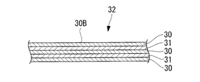
- the fiber sheet laminate according to the present disclosure is a fiber sheet laminate in which fiber sheets are laminated and an interlayer adhesive force is imparted, and the bending region in which the fiber sheet is bent and the bending region are defined. It is a different region and includes a non-bending region in which the interlayer adhesive force is stronger than the interlayer adhesive force in the bending region.
- the laminating device 1 used in the molding method according to the present embodiment includes a supply unit 2, a pressing unit 3, heating units 4 and 5, an adjusting unit 10, a control unit 8, and the like. ..
- the laminating device 1 supplies fiber sheets 30 such as prepregs one layer at a time toward the molding surface 20, places them on the molding surface 20, and then presses the placed fiber sheets 30 using the pressing portion 3. .. Next, another fiber sheet 30 is supplied and placed on the upper surface of the laminated fiber sheet 30, and is pressed by the pressing portion 3.
- the laminating device 1 is an example of a molding device according to the present disclosure.
- the fiber sheet 30 has a long tape shape in one direction, is rolled into a roll shape before being supplied, and is housed in the supply unit 2.
- the direction of the fibers in the fiber sheet 30 is arranged so as to be parallel to the longitudinal direction of the fiber sheet 30.
- the fiber sheet 30 wound in a roll shape is supplied from the supply unit 2.
- the supply unit 2 discharges the fiber sheet 30 in one direction and supplies it to the molded surface 20.
- the supply unit 2 has a structure that can be moved along the longitudinal direction and the lateral direction of the molding surface 20. In this case, while the supply unit 2 moves, the fiber sheet 30 is supplied from one end side to the other end side in the longitudinal direction of the molded surface 20 or from one end side to the other end side in the lateral direction.
- the pressing portion 3 is, for example, a roller, and presses the fiber sheet 30 placed on the molding surface 20.
- the pressing portion 3 is driven so that a predetermined pressing force (compacting force) is applied to the molded surface 20 and the fiber sheet 30. Further, the pressing portion 3 can move along the longitudinal direction and the lateral direction of the molding surface 20, and by pressing the fiber sheet 30 while the pressing portion 3 moves, one end of the long fiber sheet 30 is pressed. It can be deformed from to the other end.
- the adjusting unit 10 adjusts the interlayer adhesive force applied to the laminated fiber sheets 30.
- the adjusting unit 10 has, for example, a pressing adjusting unit 6 and a heating adjusting unit 7.
- the pressing adjustment unit 6 adjusts the pressing force applied to the fiber sheet 30 by the pressing unit 3.
- the pressing adjustment unit 6 drives the pressing unit 3 based on the signal received from the control unit 8 to increase or decrease the pressing force.
- the heating units 4 and 5 heat the fiber sheet 30 or the molded surface 20.
- the heating units 4 and 5 heat the object by, for example, infrared rays, warm air, laser light, or the like.
- the heating unit 4 is installed in front of the supply unit 2 in the moving direction, and is a fiber sheet 30 that has not been placed on the molded surface 20, the molded surface 20, or the fiber sheet 30 that has already been molded on the molded surface 20. Heat.
- the heating unit 5 is installed behind the supply unit 2 in the moving direction and heats the fiber sheet 30 before being placed on the molding surface 20. As a result, the fiber sheet 30 or the molded surface 20 is heated before the fiber sheet 30 is placed on the molded surface 20 or before the fiber sheet 30 is deformed by using the pressing portion 3. This increases the plasticity of the fiber sheet 30. As the temperature rises, the adhesiveness of the fiber sheets 30 is improved, so that the adhesiveness between the fiber sheets 30 is increased.
- the heating unit may heat the pressing unit 3 from the outside.
- a heating portion (not shown) may be provided inside the pressing portion 3 to generate heat in the pressing portion 3.
- the heat adjusting unit 7 adjusts the heating temperature applied to the fiber sheet 30.
- the heating adjusting unit 7 raises or lowers the heating temperature by the heating units 4, 5 and the like based on the signal received from the control unit 8.
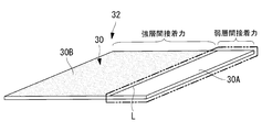
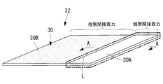
- the control unit 8 controls the pressing adjusting unit 6 or the heating adjusting unit 7 so that the interlayer adhesive force of the non-bending region 30B is stronger than the interlayer adhesive force of the bending region 30A.
- the interlayer adhesive force refers to the adhesive force acting between the fiber sheets 30 when the adjacent fiber sheets 30 adhere to each other in the laminated fiber sheets 30.
- the bending region 30A is a region where bending is performed to cause inter-slip.
- the non-bending region 30B is a region other than the bending region 30A, for example, a region adjacent to the bending region 30A.
- the control unit 8 determines the position where the fiber sheets 30 are laminated, increases the interlayer adhesive force in the non-bending region 30B, and decreases the interlayer adhesive force in the bending region 30A. It is desirable that the interlayer adhesive force of the bent region 30A is 90% or less of the interlayer adhesive force of the non-bending region 30B.
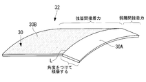
- the bending apparatus bends the fiber sheet laminate 32 in which a plurality of fiber sheets 30 are laminated so as to be a molded product having a final shape.
- the fiber sheet laminate 32 is bent along the bending line L to cause inter-slip in the bending region 30A.
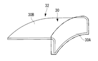
- FIG. 3 shows an example of a molded product formed by bending the fiber sheet laminate 32 shown in FIG. 2 along the bending line L.
- the bending apparatus includes, for example, a molding die having a shape corresponding to the final shape, a roller for pressing the fiber sheet laminate 32, a heating portion for heating the fiber sheet laminate 32, and the like.
- the supply unit 2 discharges the fiber sheet 30 and supplies the fiber sheet 30 to the molded surface 20 (step S1).
- the supply unit 2 supplies the fiber sheet 30 while moving from one end side to the other end side of the molded surface 20 in a predetermined direction.
- the fiber sheet 30 supplied from the supply unit 2 is placed on the molding surface 20.
- the pressing unit 3 presses the fiber sheet 30 together with the supply unit 2 while moving from one end side to the other end side of the molding surface 20 (step S2).
- the molding of the first layer fiber sheet 30 is completed.
- the interlayer adhesive force of the non-bending region 30B other than the bending region (forming area) 30A to be bent is adjusted to be stronger than the interlayer adhesive force of the bending region 30A. (Step S3).
- the supply unit 2 and the pressing unit 3 move from one end side to the other end side of the molded surface 20 in a direction different from or the same direction as that of the first layer, and the fiber sheet 30 on which the fiber sheet 30 is already placed is placed.
- the fiber sheet 30 is pressed while being supplied on the 30.
- the fiber sheet 30 is repeatedly supplied from one end side to the other end side and pressed over the entire predetermined region on the first layer fiber sheet 30, molding of the second layer fiber sheet 30 is completed.
- step S4 When the above-mentioned operation is repeated and the required number of fiber sheets 30 are laminated and molded (step S4), for example, a flat fiber sheet laminated body 32 is formed, and the laminated molding of the fiber sheet 30 is completed.
- the bending processing apparatus performs bending processing on the fiber sheet laminated body 32 in which a plurality of fiber sheets 30 are laminated so as to obtain a molded product having a final shape (step S5).
- the interlayer adhesive force of the non-bending region 30B other than the bending region (forming area) 30A to be bent is the bending region. It is adjusted to be stronger than the interlayer adhesive force of 30A. That is, the interlayer adhesive force is weakened in the bent region 30A, and the interlayer adhesive force is strengthened in the non-bent region 30B.
- the pressing force by the pressing portion 3 is adjusted to control the interlayer bonding force
- the pressing force is lowered in the bending region 30A to weaken the interlayer bonding force
- the pressing force is increased in the non-bending region 30B.
- Strengthen interlayer adhesion When controlling the interlayer adhesion by adjusting the heating temperature of the heating portions 4 and 5, the heating temperature is lowered in the bending region 30A to weaken the interlayer adhesion, and the heating temperature is raised in the non-bending region 30B. Strengthens the interlayer adhesion.
- the interlayer adhesive force is adjusted by changing the pressing force or heating temperature for each layer at the time of laminating according to the bending region 30A or the non-bending region 30B.
- the present disclosure is not limited to this example, and the pressing force or the heating temperature may be changed only at the time of the final lamination to change the interlayer adhesive force, or after the lamination is completed, the pressing force may be changed separately from the lamination step.
- the interlayer adhesion may be changed by applying pressure or heating.
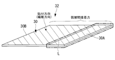
- the toe or tape sticking direction (fiber direction) of the fiber sheet 30 is parallel to the direction of the bending line L during bending, the fiber sheet 30 is laminated in the bending region 30A.
- the pressing force or the heating temperature is set so that the interlayer adhesive force is weakened.
- the pressing force or the heating temperature is adjusted so that the interlayer adhesive force of the non-bending region 30B becomes a first interlayer adhesive force stronger than the interlayer adhesive force of the bending region 30A.
- the pressing force or the heating temperature is set so that the interlayer adhesive force becomes the second interlayer adhesive force weaker than the first interlayer adhesive force.
- the fiber sheet 30 can be efficiently laminated without reducing the lamination speed.
- the present disclosure is not limited to this example, and as shown in FIG. 6, the toe or tape sticking direction of the fiber sheet 30 is orthogonal to or diagonal to the direction of the bending line L at the time of bending.
- the interlayer adhesive force may be changed when passing through the boundary between the bent region 30A and the non-bent region 30B (near the bending line L).
- the interlayer adhesive force is weakened, and when the fiber sheet 30 is laminated on the non-bent region 30B, the interlayer adhesive force is strengthened.
- the interlayer adhesive strength is changed during the lamination. Unlike the case where the interlayer adhesive force is weakened over all surfaces, the interlayer adhesion in the non-bent region 30B becomes stronger.
- the fiber sheets 30 may be laminated so as to have a bending angle of less than 180 degrees in the vicinity of the bending line L.
- the molding die used in this case has a shape in which the bending angle is larger than the bending angle of the cross-sectional shape of the molded product to be formed (see FIG. 8) and the bending angle is less than 180 degrees.
- the bending angle of the molding has an angle larger than 90 degrees.
- FIGS. 9 and 10 in the bending region 30A, a sliding material 31 having a property of being slippery than the fiber sheet 30 may be sandwiched between the fiber sheets 30.
- the sliding material 31 is, for example, a material made of a fluororesin.
- FIG. 10 is a cross-sectional view taken along the line AA of FIG.
- the fiber sheet 30 or the sliding material 31 laminated on the already arranged fiber sheet 30 is selected according to the bent region 30A or the non-bent region 30B, and the interlayer adhesive force applied to the fiber sheet 30 is adjusted. Will be done.
- the non-bent region 30B only the fiber sheet 30 is laminated, and in the bent region 30A, the fiber sheet 30 and the sliding material 31 are alternately laminated.
- the fiber sheet 30 having a property of being more slippery than the fiber sheet 30 laminated in the non-bent region 30B may be laminated.
- the material of the fiber sheet 30 laminated on the already arranged fiber sheet 30 is changed according to the bent region 30A or the non-bent region 30B, and the interlayer adhesive force applied to the fiber sheet 30 is adjusted. ..
- the fiber sheets 30 having a relatively high adhesiveness are laminated, and in the bent region 30A, the fiber sheets 30 having a relatively low adhesiveness are laminated.
- the fiber sheet 30 is supplied to a predetermined position by the supply unit 2, and the fiber sheet 30 is laminated on the fiber sheet 30 already arranged by the pressing adjustment unit 6 or the heat adjustment unit 7.
- the interlayer adhesive force applied to is adjusted.
- the fiber sheet 30 is laminated so that the interlayer adhesive force of the non-bending region 30B becomes stronger than the interlayer adhesive force of the bending region 30A by controlling the pressing adjusting unit 6 or the heating adjusting unit 7 by the control unit 8. Will be done.
- the interlayer adhesive force in the bending region 30A becomes relatively weak, so that the interlayers can be appropriately slid during the bending process, and the occurrence of wrinkles can be suppressed.
- peeling during laminating or handling can be prevented.
- the inventor used a compaction roller as the pressing portion 3, changed the pressing pressure (compacting force) applied to the pressing portion 3, and confirmed the presence or absence of wrinkles depending on the magnitude of the pressing force. ..
- the pressing force is represented by P / L [N / mm].
- P [N] is the force input to the compaction roller
- L [mm] is the length of the portion where the compaction roller comes into contact with the fiber sheet 30.
- the molding apparatus (1) includes a supply unit (2) for supplying and laminating fiber sheets (30), an adjusting unit (10) for adjusting the interlayer adhesive force applied to the laminated fiber sheets, and the like.
- the adjusting unit is controlled so that the interlayer adhesive force of the non-bending region (30B) different from the bending region (30A) to which the bending process is applied in the fiber sheet becomes stronger than the interlayer adhesive force of the bending region.
- a control unit (8) is provided.
- the fiber sheet is supplied by the supply unit, and the interlayer adhesive force applied to the laminated fiber sheets is adjusted by the adjustment unit. Further, by controlling the adjusting unit, the fiber so that the interlayer adhesive force of the non-bending region different from the bending region where the bending process is applied in the fiber sheet becomes stronger than the interlayer adhesive force of the bending region.
- the sheets are stacked. As a result, the interlayer adhesive force in the bending region becomes relatively weak, so that the interlayer can be appropriately slid during the bending process, and the occurrence of wrinkles can be suppressed. Further, in the non-bending region where the interlayer adhesive force is relatively strong, it is possible to prevent peeling during laminating or handling.
- the adjusting unit has a pressing adjusting unit (6) for adjusting the pressing force applied to the fiber sheet, and the controlling unit is said to be more than the bending region in the non-bending region.
- the pressing force adjusted by the pressing adjusting unit may be controlled so that the pressing force applied to the fiber sheet increases.
- the pressing force applied to the fiber sheet is adjusted so that the pressing force applied to the fiber sheet is higher than that in the bent region in the non-bending region, and the interlayer adhesive force applied to the fiber sheet is adjusted. Will be done. As a result, the interlayer adhesive force in the non-bent region becomes stronger than the interlayer adhesive force in the bent region.
- the pressing adjustment unit may adjust the pressing force when laminating the fiber sheets.
- the pressing force is changed only at the time of laminating the fiber sheets, for example, for each layer or at the time of the final laminating, and the interlayer adhesive force is changed.
- the pressing adjustment unit may adjust the pressing force after the laminating of the fiber sheets is completed.
- the pressing force is changed after the laminating of the fiber sheets is completed, and the interlayer adhesive force is changed.
- the adjusting unit has a heating adjusting unit (7) for adjusting the heating temperature applied to the fiber sheet, and the control unit is said to be more than the bending region in the non-bending region.
- the heating temperature adjusted by the heating adjusting unit may be controlled so that the heating temperature applied to the fiber sheet rises.
- the heating temperature applied to the fiber sheet is adjusted so that the heating temperature applied to the fiber sheet is higher than that in the bent region in the non-bent region, and the interlayer adhesive force applied to the fiber sheet is adjusted. Will be done. As a result, the interlayer adhesive force in the non-bent region becomes stronger than the interlayer adhesive force in the bent region.
- the heating adjusting unit may adjust the heating temperature when laminating the fiber sheets.
- the heating temperature is changed only at the time of laminating the fiber sheets, for example, for each layer or at the time of the final laminating, and the interlayer adhesive strength is changed.
- the heating adjusting unit may adjust the heating temperature after the laminating of the fiber sheets is completed.
- the heating temperature is changed after the laminating of the fiber sheets is completed, and the interlayer adhesive strength is changed.
- the molding method according to the present disclosure includes a laminating step of supplying and laminating the fiber sheet (30) and an adjusting step of adjusting the interlayer adhesive force applied to the laminated fiber sheet, and the adjusting step is the fiber.
- the interlayer adhesive force is adjusted so that the interlayer adhesive force of the non-bending region (30B) different from the bending region (30A) to which the sheet is bent is stronger than the interlayer adhesive force of the bending region. To do.
- the fiber sheets are supplied and laminated, and the interlayer adhesive force applied to the laminated fiber sheets is adjusted. Further, the fiber sheets are laminated so that the interlayer adhesive force of the non-bending region different from the bending region to be bent in the fiber sheet is stronger than the interlayer adhesive force of the bending region. As a result, the interlayer adhesive force in the bending region becomes relatively weak, so that the interlayer can be appropriately slid during the bending process, and the occurrence of wrinkles can be suppressed. Further, in a region where the interlayer adhesive force is relatively strong, it is possible to prevent peeling during laminating or handling.
- a second laminating step of supplying and laminating a sliding material (31) having a property of being slippery than the fiber sheet at a predetermined position is further provided, and the adjusting step is already arranged.
- the fiber sheet or the sliding material laminated on the fiber sheet may be selected.
- a sliding material having a property of being slippery than a fiber sheet is supplied to a predetermined position and laminated. Further, depending on the bent region or the non-bent region, the fiber sheet or the sliding material laminated on the already arranged fiber sheet is selected, and the interlayer adhesive force applied to the fiber sheet is adjusted.
- the adjustment step may change the material of the fiber sheet laminated on the already arranged fiber sheet.
- the material of the fiber sheet laminated on the already arranged fiber sheet is changed according to the bent region or the non-bent region, and the interlayer adhesive force applied to the fiber sheet is adjusted.
- the interlayer adhesive force of the non-bending region at the time of laminating the fiber sheet when the sticking direction of the fiber sheet is parallel to the direction of the bending line at the time of the bending process, the interlayer adhesive force of the non-bending region at the time of laminating the fiber sheet.
- the interlayer adhesive force may be adjusted so that the first interlayer adhesive force is stronger than the interlayer adhesive force of the bending region.
- the interlayer adhesive force is set to be weak when the fiber sheet is laminated in the bending region.
- the interlayer adhesive force is set to be strong.
- the interlayer adhesive force may be adjusted so that the second interlayer adhesive force is weaker than the first interlayer adhesive force.
- the interlayer adhesive force is set to be weak regardless of the bending region and the non-bending region.
- the non-bending region is said to be said.
- the interlayer adhesive force may be adjusted so that the interlayer adhesive force is stronger than the interlayer adhesive force in the bending region.
- the interlayer adhesive force When the fiber sheet is attached in a direction orthogonal to the direction of the bending line at the time of bending or diagonally, when passing through the boundary between the bending region and the non-bending region (near the bending line), the interlayer adhesive force is changed. May be good. When laminating the fiber sheet in the bent region, the interlayer adhesive force is weakened, and when laminating the fiber sheet in the non-bent region, the interlayer adhesive force is strengthened.
- the fiber sheet laminate according to the present disclosure is a fiber sheet laminate in which fiber sheets are laminated and an interlayer adhesive force is applied, and the bending region of the fiber sheet to be bent is different from the bending region. It is a region, and includes a non-bending region in which the interlayer adhesive force is stronger than the interlayer adhesive force in the bending region.
- the fiber sheets are laminated so that the interlayer adhesive force of the non-bending region different from the bending region to be bent in the fiber sheet is stronger than the interlayer adhesive force of the bending region.
- the interlayer adhesive force in the bending region becomes relatively weak, so that the interlayer can be appropriately slid during the bending process, and the occurrence of wrinkles can be suppressed.
- the non-bending region where the interlayer adhesive force is relatively strong it is possible to prevent peeling during laminating or handling.
- a sliding material having a property of being slippery than the fiber sheet may be laminated between a plurality of the fiber sheets.
- a sliding material having a property of being slippery than a fiber sheet is supplied to a predetermined position and laminated. Further, depending on the bent region or the non-bent region, the fiber sheet or the sliding material laminated on the already arranged fiber sheet is selected, and the interlayer adhesive force applied to the fiber sheet is adjusted.
- Adjustment unit 20 Molded surface 30: Fiber sheet 30A: Bending region 30B: Non-bending region 31: Sliding material 32: Fiber sheet laminate L: Bending line
Landscapes
- Engineering & Computer Science (AREA)
- Mechanical Engineering (AREA)
- Chemical & Material Sciences (AREA)
- Composite Materials (AREA)
- Robotics (AREA)
- Moulding By Coating Moulds (AREA)
- Shaping Of Tube Ends By Bending Or Straightening (AREA)
- Laminated Bodies (AREA)
Priority Applications (3)
| Application Number | Priority Date | Filing Date | Title |
|---|---|---|---|
| JP2021560798A JP7254964B2 (ja) | 2019-11-26 | 2019-11-26 | 成形装置、成形方法及び繊維シート積層体 |
| EP19954345.5A EP4000912B1 (en) | 2019-11-26 | 2019-11-26 | Lamination device and forming method |
| PCT/JP2019/046155 WO2021106070A1 (ja) | 2019-11-26 | 2019-11-26 | 成形装置、成形方法及び繊維シート積層体 |
Applications Claiming Priority (1)
| Application Number | Priority Date | Filing Date | Title |
|---|---|---|---|
| PCT/JP2019/046155 WO2021106070A1 (ja) | 2019-11-26 | 2019-11-26 | 成形装置、成形方法及び繊維シート積層体 |
Publications (1)
| Publication Number | Publication Date |
|---|---|
| WO2021106070A1 true WO2021106070A1 (ja) | 2021-06-03 |
Family
ID=76129377
Family Applications (1)
| Application Number | Title | Priority Date | Filing Date |
|---|---|---|---|
| PCT/JP2019/046155 Ceased WO2021106070A1 (ja) | 2019-11-26 | 2019-11-26 | 成形装置、成形方法及び繊維シート積層体 |
Country Status (3)
| Country | Link |
|---|---|
| EP (1) | EP4000912B1 (https=) |
| JP (1) | JP7254964B2 (https=) |
| WO (1) | WO2021106070A1 (https=) |
Cited By (1)
| Publication number | Priority date | Publication date | Assignee | Title |
|---|---|---|---|---|
| CN114368134A (zh) * | 2022-01-18 | 2022-04-19 | 宁波江丰复合材料科技有限公司 | 一种碳纤维管件的矫直方法 |
Citations (4)
| Publication number | Priority date | Publication date | Assignee | Title |
|---|---|---|---|---|
| JPH0747596A (ja) * | 1993-08-03 | 1995-02-21 | Mitsubishi Heavy Ind Ltd | 繊維強化熱可塑性樹脂系複合材料の曲げ成形法 |
| JPH07108529A (ja) * | 1993-10-12 | 1995-04-25 | Honda Motor Co Ltd | 熱可塑性複合材及びそのプリフォーム体の製造方法 |
| US20080210372A1 (en) | 2007-03-01 | 2008-09-04 | Cumings Robert C | Composite article debulking process |
| JP2019151083A (ja) * | 2018-03-06 | 2019-09-12 | 株式会社Subaru | プリフォーム賦形方法及び複合材成形方法 |
Family Cites Families (1)
| Publication number | Priority date | Publication date | Assignee | Title |
|---|---|---|---|---|
| JP2014051065A (ja) * | 2012-09-10 | 2014-03-20 | Mitsubishi Heavy Ind Ltd | プリプレグ積層材の成形装置および成形方法 |
-
2019
- 2019-11-26 WO PCT/JP2019/046155 patent/WO2021106070A1/ja not_active Ceased
- 2019-11-26 JP JP2021560798A patent/JP7254964B2/ja active Active
- 2019-11-26 EP EP19954345.5A patent/EP4000912B1/en active Active
Patent Citations (4)
| Publication number | Priority date | Publication date | Assignee | Title |
|---|---|---|---|---|
| JPH0747596A (ja) * | 1993-08-03 | 1995-02-21 | Mitsubishi Heavy Ind Ltd | 繊維強化熱可塑性樹脂系複合材料の曲げ成形法 |
| JPH07108529A (ja) * | 1993-10-12 | 1995-04-25 | Honda Motor Co Ltd | 熱可塑性複合材及びそのプリフォーム体の製造方法 |
| US20080210372A1 (en) | 2007-03-01 | 2008-09-04 | Cumings Robert C | Composite article debulking process |
| JP2019151083A (ja) * | 2018-03-06 | 2019-09-12 | 株式会社Subaru | プリフォーム賦形方法及び複合材成形方法 |
Non-Patent Citations (1)
| Title |
|---|
| See also references of EP4000912A4 |
Cited By (2)
| Publication number | Priority date | Publication date | Assignee | Title |
|---|---|---|---|---|
| CN114368134A (zh) * | 2022-01-18 | 2022-04-19 | 宁波江丰复合材料科技有限公司 | 一种碳纤维管件的矫直方法 |
| CN114368134B (zh) * | 2022-01-18 | 2023-12-29 | 宁波江丰复合材料科技有限公司 | 一种碳纤维管件的矫直方法 |
Also Published As
| Publication number | Publication date |
|---|---|
| EP4000912B1 (en) | 2026-04-01 |
| JP7254964B2 (ja) | 2023-04-10 |
| EP4000912A4 (en) | 2022-07-20 |
| JPWO2021106070A1 (https=) | 2021-06-03 |
| EP4000912A1 (en) | 2022-05-25 |
Similar Documents
| Publication | Publication Date | Title |
|---|---|---|
| JP3742082B2 (ja) | 曲率を有した繊維強化プラスチック部材の連続成形方法及び装置 | |
| EP2911889A1 (de) | HEIßPRÄGEVORRICHTUNG | |
| US10913222B2 (en) | Method for producing composite material component and device for producing composite material component | |
| CN105492209A (zh) | 用于制造夹芯复合材料的方法和设备 | |
| JP2013244684A (ja) | ガラス基材含有積層体の製造方法 | |
| WO2017042920A1 (ja) | 複合材料の製造方法、複合材料の製造装置、複合材料用プリフォームおよび複合材料 | |
| JP7254964B2 (ja) | 成形装置、成形方法及び繊維シート積層体 | |
| EP4000911B1 (en) | Forming method | |
| JP3119886B2 (ja) | プリプレグの積層方法及びその装置 | |
| JP6409569B2 (ja) | 繊維強化プラスチックの製造方法 | |
| CN113784844A (zh) | 用于粘结柔性膜的方法和用于实施该方法的装置 | |
| JP2020082723A (ja) | 連続圧縮成形プロセスを使用して形成される、多孔質コアを有する複合積層構造 | |
| JPH06238758A (ja) | プリプレグ材料の成形装置 | |
| KR20190125640A (ko) | 삼중 접합강판과 그 접합강판 연속제조장치 및 제조방법 | |
| JP5599434B2 (ja) | 積層成形システムおよび積層成形方法 | |
| JP6045293B2 (ja) | 積層シートの製造方法 | |
| US12134223B2 (en) | Molding device and molding method | |
| KR20060050105A (ko) | 열가소성 수지 적층 시트의 제조 방법 | |
| JP5645225B2 (ja) | 積層成形システムおよび積層成形方法 | |
| KR102311720B1 (ko) | 라미네이트 필름 제조방법 | |
| EP3865293B1 (en) | Composite material and method of forming composite material | |
| WO2023176130A1 (ja) | 積層成形システムおよび積層成形方法 | |
| JPWO2020162027A1 (ja) | 積層体成形装置及び積層体成形方法 | |
| JPS6354545B2 (https=) | ||
| JP2020055313A (ja) | 曲面積層体の製造方法および製造装置 |
Legal Events
| Date | Code | Title | Description |
|---|---|---|---|
| 121 | Ep: the epo has been informed by wipo that ep was designated in this application |
Ref document number: 19954345 Country of ref document: EP Kind code of ref document: A1 |
|
| ENP | Entry into the national phase |
Ref document number: 2021560798 Country of ref document: JP Kind code of ref document: A |
|
| ENP | Entry into the national phase |
Ref document number: 2019954345 Country of ref document: EP Effective date: 20220215 |
|
| NENP | Non-entry into the national phase |
Ref country code: DE |
|
| WWG | Wipo information: grant in national office |
Ref document number: 2019954345 Country of ref document: EP |