WO2017042920A1 - 複合材料の製造方法、複合材料の製造装置、複合材料用プリフォームおよび複合材料 - Google Patents
複合材料の製造方法、複合材料の製造装置、複合材料用プリフォームおよび複合材料 Download PDFInfo
- Publication number
- WO2017042920A1 WO2017042920A1 PCT/JP2015/075647 JP2015075647W WO2017042920A1 WO 2017042920 A1 WO2017042920 A1 WO 2017042920A1 JP 2015075647 W JP2015075647 W JP 2015075647W WO 2017042920 A1 WO2017042920 A1 WO 2017042920A1
- Authority
- WO
- WIPO (PCT)
- Prior art keywords
- region
- adhesive
- composite material
- preform
- reinforced
- Prior art date
Links
Images


Classifications
-
- B—PERFORMING OPERATIONS; TRANSPORTING
- B26—HAND CUTTING TOOLS; CUTTING; SEVERING
- B26D—CUTTING; DETAILS COMMON TO MACHINES FOR PERFORATING, PUNCHING, CUTTING-OUT, STAMPING-OUT OR SEVERING
- B26D7/00—Details of apparatus for cutting, cutting-out, stamping-out, punching, perforating, or severing by means other than cutting
- B26D7/08—Means for treating work or cutting member to facilitate cutting
- B26D7/086—Means for treating work or cutting member to facilitate cutting by vibrating, e.g. ultrasonically
-
- B—PERFORMING OPERATIONS; TRANSPORTING
- B26—HAND CUTTING TOOLS; CUTTING; SEVERING
- B26F—PERFORATING; PUNCHING; CUTTING-OUT; STAMPING-OUT; SEVERING BY MEANS OTHER THAN CUTTING
- B26F1/00—Perforating; Punching; Cutting-out; Stamping-out; Apparatus therefor
- B26F1/38—Cutting-out; Stamping-out
- B26F1/3806—Cutting-out; Stamping-out wherein relative movements of tool head and work during cutting have a component tangential to the work surface
- B26F1/3813—Cutting-out; Stamping-out wherein relative movements of tool head and work during cutting have a component tangential to the work surface wherein the tool head is moved in a plane parallel to the work in a coordinate system fixed with respect to the work
-
- B—PERFORMING OPERATIONS; TRANSPORTING
- B29—WORKING OF PLASTICS; WORKING OF SUBSTANCES IN A PLASTIC STATE IN GENERAL
- B29B—PREPARATION OR PRETREATMENT OF THE MATERIAL TO BE SHAPED; MAKING GRANULES OR PREFORMS; RECOVERY OF PLASTICS OR OTHER CONSTITUENTS OF WASTE MATERIAL CONTAINING PLASTICS
- B29B11/00—Making preforms
- B29B11/14—Making preforms characterised by structure or composition
- B29B11/16—Making preforms characterised by structure or composition comprising fillers or reinforcement
-
- B—PERFORMING OPERATIONS; TRANSPORTING
- B29—WORKING OF PLASTICS; WORKING OF SUBSTANCES IN A PLASTIC STATE IN GENERAL
- B29C—SHAPING OR JOINING OF PLASTICS; SHAPING OF MATERIAL IN A PLASTIC STATE, NOT OTHERWISE PROVIDED FOR; AFTER-TREATMENT OF THE SHAPED PRODUCTS, e.g. REPAIRING
- B29C63/00—Lining or sheathing, i.e. applying preformed layers or sheathings of plastics; Apparatus therefor
- B29C63/02—Lining or sheathing, i.e. applying preformed layers or sheathings of plastics; Apparatus therefor using sheet or web-like material
- B29C63/04—Lining or sheathing, i.e. applying preformed layers or sheathings of plastics; Apparatus therefor using sheet or web-like material by folding, winding, bending or the like
-
- B—PERFORMING OPERATIONS; TRANSPORTING
- B29—WORKING OF PLASTICS; WORKING OF SUBSTANCES IN A PLASTIC STATE IN GENERAL
- B29C—SHAPING OR JOINING OF PLASTICS; SHAPING OF MATERIAL IN A PLASTIC STATE, NOT OTHERWISE PROVIDED FOR; AFTER-TREATMENT OF THE SHAPED PRODUCTS, e.g. REPAIRING
- B29C65/00—Joining or sealing of preformed parts, e.g. welding of plastics materials; Apparatus therefor
- B29C65/48—Joining or sealing of preformed parts, e.g. welding of plastics materials; Apparatus therefor using adhesives, i.e. using supplementary joining material; solvent bonding
- B29C65/4805—Joining or sealing of preformed parts, e.g. welding of plastics materials; Apparatus therefor using adhesives, i.e. using supplementary joining material; solvent bonding characterised by the type of adhesives
-
- B—PERFORMING OPERATIONS; TRANSPORTING
- B29—WORKING OF PLASTICS; WORKING OF SUBSTANCES IN A PLASTIC STATE IN GENERAL
- B29C—SHAPING OR JOINING OF PLASTICS; SHAPING OF MATERIAL IN A PLASTIC STATE, NOT OTHERWISE PROVIDED FOR; AFTER-TREATMENT OF THE SHAPED PRODUCTS, e.g. REPAIRING
- B29C70/00—Shaping composites, i.e. plastics material comprising reinforcements, fillers or preformed parts, e.g. inserts
- B29C70/04—Shaping composites, i.e. plastics material comprising reinforcements, fillers or preformed parts, e.g. inserts comprising reinforcements only, e.g. self-reinforcing plastics
- B29C70/28—Shaping operations therefor
- B29C70/30—Shaping by lay-up, i.e. applying fibres, tape or broadsheet on a mould, former or core; Shaping by spray-up, i.e. spraying of fibres on a mould, former or core
- B29C70/34—Shaping by lay-up, i.e. applying fibres, tape or broadsheet on a mould, former or core; Shaping by spray-up, i.e. spraying of fibres on a mould, former or core and shaping or impregnating by compression, i.e. combined with compressing after the lay-up operation
- B29C70/345—Shaping by lay-up, i.e. applying fibres, tape or broadsheet on a mould, former or core; Shaping by spray-up, i.e. spraying of fibres on a mould, former or core and shaping or impregnating by compression, i.e. combined with compressing after the lay-up operation using matched moulds
-
- B—PERFORMING OPERATIONS; TRANSPORTING
- B29—WORKING OF PLASTICS; WORKING OF SUBSTANCES IN A PLASTIC STATE IN GENERAL
- B29C—SHAPING OR JOINING OF PLASTICS; SHAPING OF MATERIAL IN A PLASTIC STATE, NOT OTHERWISE PROVIDED FOR; AFTER-TREATMENT OF THE SHAPED PRODUCTS, e.g. REPAIRING
- B29C70/00—Shaping composites, i.e. plastics material comprising reinforcements, fillers or preformed parts, e.g. inserts
- B29C70/04—Shaping composites, i.e. plastics material comprising reinforcements, fillers or preformed parts, e.g. inserts comprising reinforcements only, e.g. self-reinforcing plastics
- B29C70/28—Shaping operations therefor
- B29C70/40—Shaping or impregnating by compression not applied
- B29C70/42—Shaping or impregnating by compression not applied for producing articles of definite length, i.e. discrete articles
- B29C70/46—Shaping or impregnating by compression not applied for producing articles of definite length, i.e. discrete articles using matched moulds, e.g. for deforming sheet moulding compounds [SMC] or prepregs
- B29C70/48—Shaping or impregnating by compression not applied for producing articles of definite length, i.e. discrete articles using matched moulds, e.g. for deforming sheet moulding compounds [SMC] or prepregs and impregnating the reinforcements in the closed mould, e.g. resin transfer moulding [RTM], e.g. by vacuum
-
- B—PERFORMING OPERATIONS; TRANSPORTING
- B29—WORKING OF PLASTICS; WORKING OF SUBSTANCES IN A PLASTIC STATE IN GENERAL
- B29C—SHAPING OR JOINING OF PLASTICS; SHAPING OF MATERIAL IN A PLASTIC STATE, NOT OTHERWISE PROVIDED FOR; AFTER-TREATMENT OF THE SHAPED PRODUCTS, e.g. REPAIRING
- B29C70/00—Shaping composites, i.e. plastics material comprising reinforcements, fillers or preformed parts, e.g. inserts
- B29C70/04—Shaping composites, i.e. plastics material comprising reinforcements, fillers or preformed parts, e.g. inserts comprising reinforcements only, e.g. self-reinforcing plastics
- B29C70/28—Shaping operations therefor
- B29C70/54—Component parts, details or accessories; Auxiliary operations, e.g. feeding or storage of prepregs or SMC after impregnation or during ageing
- B29C70/545—Perforating, cutting or machining during or after moulding
-
- B—PERFORMING OPERATIONS; TRANSPORTING
- B32—LAYERED PRODUCTS
- B32B—LAYERED PRODUCTS, i.e. PRODUCTS BUILT-UP OF STRATA OF FLAT OR NON-FLAT, e.g. CELLULAR OR HONEYCOMB, FORM
- B32B1/00—Layered products having a general shape other than plane
-
- B—PERFORMING OPERATIONS; TRANSPORTING
- B32—LAYERED PRODUCTS
- B32B—LAYERED PRODUCTS, i.e. PRODUCTS BUILT-UP OF STRATA OF FLAT OR NON-FLAT, e.g. CELLULAR OR HONEYCOMB, FORM
- B32B27/00—Layered products comprising a layer of synthetic resin
- B32B27/06—Layered products comprising a layer of synthetic resin as the main or only constituent of a layer, which is next to another layer of the same or of a different material
- B32B27/08—Layered products comprising a layer of synthetic resin as the main or only constituent of a layer, which is next to another layer of the same or of a different material of synthetic resin
-
- B—PERFORMING OPERATIONS; TRANSPORTING
- B32—LAYERED PRODUCTS
- B32B—LAYERED PRODUCTS, i.e. PRODUCTS BUILT-UP OF STRATA OF FLAT OR NON-FLAT, e.g. CELLULAR OR HONEYCOMB, FORM
- B32B27/00—Layered products comprising a layer of synthetic resin
- B32B27/38—Layered products comprising a layer of synthetic resin comprising epoxy resins
-
- B—PERFORMING OPERATIONS; TRANSPORTING
- B32—LAYERED PRODUCTS
- B32B—LAYERED PRODUCTS, i.e. PRODUCTS BUILT-UP OF STRATA OF FLAT OR NON-FLAT, e.g. CELLULAR OR HONEYCOMB, FORM
- B32B7/00—Layered products characterised by the relation between layers; Layered products characterised by the relative orientation of features between layers, or by the relative values of a measurable parameter between layers, i.e. products comprising layers having different physical, chemical or physicochemical properties; Layered products characterised by the interconnection of layers
- B32B7/02—Physical, chemical or physicochemical properties
-
- B—PERFORMING OPERATIONS; TRANSPORTING
- B32—LAYERED PRODUCTS
- B32B—LAYERED PRODUCTS, i.e. PRODUCTS BUILT-UP OF STRATA OF FLAT OR NON-FLAT, e.g. CELLULAR OR HONEYCOMB, FORM
- B32B7/00—Layered products characterised by the relation between layers; Layered products characterised by the relative orientation of features between layers, or by the relative values of a measurable parameter between layers, i.e. products comprising layers having different physical, chemical or physicochemical properties; Layered products characterised by the interconnection of layers
- B32B7/04—Interconnection of layers
- B32B7/12—Interconnection of layers using interposed adhesives or interposed materials with bonding properties
-
- B—PERFORMING OPERATIONS; TRANSPORTING
- B29—WORKING OF PLASTICS; WORKING OF SUBSTANCES IN A PLASTIC STATE IN GENERAL
- B29C—SHAPING OR JOINING OF PLASTICS; SHAPING OF MATERIAL IN A PLASTIC STATE, NOT OTHERWISE PROVIDED FOR; AFTER-TREATMENT OF THE SHAPED PRODUCTS, e.g. REPAIRING
- B29C2793/00—Shaping techniques involving a cutting or machining operation
- B29C2793/0081—Shaping techniques involving a cutting or machining operation before shaping
-
- B—PERFORMING OPERATIONS; TRANSPORTING
- B29—WORKING OF PLASTICS; WORKING OF SUBSTANCES IN A PLASTIC STATE IN GENERAL
- B29K—INDEXING SCHEME ASSOCIATED WITH SUBCLASSES B29B, B29C OR B29D, RELATING TO MOULDING MATERIALS OR TO MATERIALS FOR MOULDS, REINFORCEMENTS, FILLERS OR PREFORMED PARTS, e.g. INSERTS
- B29K2063/00—Use of EP, i.e. epoxy resins or derivatives thereof, as moulding material
-
- B—PERFORMING OPERATIONS; TRANSPORTING
- B29—WORKING OF PLASTICS; WORKING OF SUBSTANCES IN A PLASTIC STATE IN GENERAL
- B29K—INDEXING SCHEME ASSOCIATED WITH SUBCLASSES B29B, B29C OR B29D, RELATING TO MOULDING MATERIALS OR TO MATERIALS FOR MOULDS, REINFORCEMENTS, FILLERS OR PREFORMED PARTS, e.g. INSERTS
- B29K2105/00—Condition, form or state of moulded material or of the material to be shaped
- B29K2105/06—Condition, form or state of moulded material or of the material to be shaped containing reinforcements, fillers or inserts
- B29K2105/08—Condition, form or state of moulded material or of the material to be shaped containing reinforcements, fillers or inserts of continuous length, e.g. cords, rovings, mats, fabrics, strands or yarns
- B29K2105/0872—Prepregs
- B29K2105/0881—Prepregs unidirectional
-
- B—PERFORMING OPERATIONS; TRANSPORTING
- B29—WORKING OF PLASTICS; WORKING OF SUBSTANCES IN A PLASTIC STATE IN GENERAL
- B29K—INDEXING SCHEME ASSOCIATED WITH SUBCLASSES B29B, B29C OR B29D, RELATING TO MOULDING MATERIALS OR TO MATERIALS FOR MOULDS, REINFORCEMENTS, FILLERS OR PREFORMED PARTS, e.g. INSERTS
- B29K2307/00—Use of elements other than metals as reinforcement
- B29K2307/04—Carbon
-
- B—PERFORMING OPERATIONS; TRANSPORTING
- B32—LAYERED PRODUCTS
- B32B—LAYERED PRODUCTS, i.e. PRODUCTS BUILT-UP OF STRATA OF FLAT OR NON-FLAT, e.g. CELLULAR OR HONEYCOMB, FORM
- B32B2260/00—Layered product comprising an impregnated, embedded, or bonded layer wherein the layer comprises an impregnation, embedding, or binder material
- B32B2260/02—Composition of the impregnated, bonded or embedded layer
- B32B2260/021—Fibrous or filamentary layer
-
- B—PERFORMING OPERATIONS; TRANSPORTING
- B32—LAYERED PRODUCTS
- B32B—LAYERED PRODUCTS, i.e. PRODUCTS BUILT-UP OF STRATA OF FLAT OR NON-FLAT, e.g. CELLULAR OR HONEYCOMB, FORM
- B32B2260/00—Layered product comprising an impregnated, embedded, or bonded layer wherein the layer comprises an impregnation, embedding, or binder material
- B32B2260/04—Impregnation, embedding, or binder material
- B32B2260/046—Synthetic resin
-
- B—PERFORMING OPERATIONS; TRANSPORTING
- B32—LAYERED PRODUCTS
- B32B—LAYERED PRODUCTS, i.e. PRODUCTS BUILT-UP OF STRATA OF FLAT OR NON-FLAT, e.g. CELLULAR OR HONEYCOMB, FORM
- B32B2262/00—Composition or structural features of fibres which form a fibrous or filamentary layer or are present as additives
- B32B2262/10—Inorganic fibres
- B32B2262/106—Carbon fibres, e.g. graphite fibres
-
- B—PERFORMING OPERATIONS; TRANSPORTING
- B32—LAYERED PRODUCTS
- B32B—LAYERED PRODUCTS, i.e. PRODUCTS BUILT-UP OF STRATA OF FLAT OR NON-FLAT, e.g. CELLULAR OR HONEYCOMB, FORM
- B32B2307/00—Properties of the layers or laminate
- B32B2307/70—Other properties
- B32B2307/72—Density
- B32B2307/722—Non-uniform density
Definitions
- the present invention relates to a composite material manufacturing method, a composite material manufacturing apparatus, a composite material preform, and a composite material.
- the reinforced base material is laminated and preformed before being placed in a mold, and is formed into a preform having a predetermined shape.
- a method for forming the preform for example, a predetermined number of sheet-like reinforcing substrates are laminated as in Patent Document 1 below, placed in a preforming die, and pressed to be molded into a predetermined shape.
- Patent Document 1 a predetermined number of sheet-like reinforcing substrates are laminated as in Patent Document 1 below, placed in a preforming die, and pressed to be molded into a predetermined shape.
- the arrangement of the reinforced base material varies when the laminated reinforced base material is conveyed to the preforming mold. For this reason, the method of suppressing the dispersion
- the reinforced base material is hardly deformed when the reinforced base material is pressed into a predetermined shape.
- a shape having a corner with a large curvature is difficult to mold, and there is a risk that the preform will be wrinkled or twisted.
- the range of the shape selection of the composite material which is a molded article was narrow.
- the present invention has been made to solve the above-described problems, and a composite material having a wide range of shape selection can be obtained by increasing the degree of freedom of the shape of the preform while suppressing variations in the arrangement of the reinforcing fibers. It is an object of the present invention to provide a composite material manufacturing method, a composite material manufacturing apparatus, a composite material preform, and a composite material that can be molded.
- the method for producing a composite material according to the present invention for achieving the above object is a method for producing a composite material comprising a reinforced base material and a resin impregnated in the reinforced base material.
- the adhesive is added to the sheet-shaped reinforced substrate including the first region and the second region so that the density of the adhesive in the second region is lower than that in the first region.
- the reinforced base material is preformed into a three-dimensional shape in which the curvature of the second region is larger than that of the first region.
- An apparatus for manufacturing a composite material according to the present invention that achieves the above-mentioned object defines an applying portion that applies an adhesive to a sheet-like reinforcing substrate having a first region and a second region, and the reinforcing substrate.
- a preforming mold for preforming into a three-dimensional shape, and a controller for controlling the operation of the applying unit and the preforming mold.
- the control unit controls the operation of the applying unit so that the adhesive material is applied to the reinforced base material with a lower density of the adhesive in the second region than in the first region, and
- the operation of the preforming mold is controlled so that the reinforced base material is molded into a three-dimensional shape having a curvature of the second region larger than that of the first region.
- the composite material preform according to the present invention that achieves the above object is a composite material preform formed by impregnating a reinforcing substrate with an adhesive.
- the reinforced substrate includes a first region and a second region having a lower density of the adhesive than the first region, and the curvature in the first region is higher than that of the second region. large.
- the composite material according to the present invention that achieves the above object is a composite material formed using a preform formed by impregnating a reinforcing substrate with an adhesive.
- the reinforced substrate includes a first region and a second region having a lower density of the adhesive than the first region, and the curvature in the first region is higher than that of the second region. large.
- FIG. 2 (A) is a general
- FIG. 2 (B) is a general
- FIGS. 3A and 3B are views for explaining a preforming apparatus for molding a preform according to an embodiment of the present invention
- FIG. 3A is an overview perspective view of a cutting portion
- FIG. 3B is an overview of a preforming die. It is a perspective view.
- FIG. 5A is a view showing the content density distribution of the adhesive in the reinforced base material
- FIG. 5B is an explanatory view showing the content density distribution of the adhesive of the preform that has been preformed. It is a figure for demonstrating the provision width
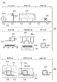
- FIG. 9A is a view showing an automobile part manufactured by applying the composite material manufacturing method according to the embodiment of the present invention
- FIG. 9A is a view showing various automobile parts using the composite material
- FIG. ) Is a view showing a vehicle body formed by joining automobile parts.
- FIG. 1 is a diagram for explaining the overall flow of a manufacturing apparatus 100 and a manufacturing method for a composite material 400 according to an embodiment of the present invention.
- 2 and 3 are views for explaining a preforming apparatus 200 for forming a preform 500 according to the embodiment of the present invention.
- FIG. 4 is a schematic view of a molding apparatus 300 that molds the composite material 400 using the preform 500 according to the embodiment of the present invention.
- FIG. 5 is a diagram showing a content density distribution of the adhesive 520 in the reinforced substrate 510.
- FIG. 6 is a diagram for explaining the application width W of the adhesive 520 in the vicinity of the cutting line L of the reinforced base material 510 cut by the cutting portion 240.
- FIG. 1 is a diagram for explaining the overall flow of a manufacturing apparatus 100 and a manufacturing method for a composite material 400 according to an embodiment of the present invention.
- 2 and 3 are views for explaining a preforming apparatus 200 for forming a preform 500 according to the embodiment of the present invention.
- FIG. 4
- FIG. 7 is a flowchart showing a method of forming the preform 500 according to the embodiment of the present invention.
- FIG. 8 is a flowchart showing a method of forming the composite material 400 according to the embodiment of the present invention.
- FIG. 9 is a perspective view showing automobile parts 701 to 703 and a vehicle body 700 using the composite material 400 according to the embodiment of the present invention.
- the arrow in FIG. 2 and FIG. 3 (A) has shown the conveyance direction (direction which goes to a downstream process) of the reinforced base material 510 by the conveyance part 210.
- FIG.3 (B) has shown the shaping
- the preform 500 is formed by impregnating a reinforcing substrate 510 with an adhesive 520.
- the reinforced substrate 510 can be formed of, for example, carbon fiber, glass fiber, organic fiber, or the like.
- carbon fiber is used as the reinforcing base 510. Since the carbon fiber 510 is characterized by a small coefficient of thermal expansion, excellent dimensional stability, and little deterioration in mechanical properties even at high temperatures, it is suitable as a reinforcing base material for the composite material 400 such as the automobile body 700. Can be used.
- the carbon fiber 510 is, for example, a so-called NCF in which a UD (unidirectional) material in which fibers are aligned in one direction or a plurality of sheets in which fibers are aligned in one direction are stacked in different directions and integrated with auxiliary fibers.
- a sheet-like carbon fiber 510 such as a (non-crimp fabric) material can be used.
- the laminated structure depends on material properties required for the composite material 400 that is a molded product, but is generally laminated so as to have a plurality of orientation angles. In this embodiment, it is set as the lamination
- the adhesive 520 is applied to the carbon fibers 510 to bond the carbon fibers 510 to each other.
- the carbon fibers 510 can be stably maintained in a sheet-like form, and variations in the arrangement of the carbon fibers 510 can be suppressed.
- the laminated body 510b (refer FIG. 3 (B)) of the carbon fiber 510 is shape
- the material constituting the adhesive 520 is not particularly limited, and a known material can be used. Examples thereof include thermoplastic resins such as polyolefin resin, styrene resin, nylon resin, and polyurethane resin, and thermosetting resins such as epoxy resin, phenol resin, and unsaturated polyester resin.
- thermoplastic resins such as polyolefin resin, styrene resin, nylon resin, and polyurethane resin
- thermosetting resins such as epoxy resin, phenol resin, and unsaturated polyester resin.
- a low-molecular weight epoxy resin that is the same thermosetting resin as the resin used for the composite material 400 described later, has high fluidity because of low melt viscosity, and is excellent in heat resistance and moisture resistance.
- the carbon fiber 510 includes the first region 511 to which the adhesive 520 is applied, and the adhesive 520 so that the density of the adhesive 520 is lower than that of the first region 511.
- “the content density of the adhesive 520 is low” includes a case where the adhesive 520 is not applied, that is, a case where the content density is 0 (zero).
- the first region 511 is molded so that the curvature is larger than that of the second region 512.
- the second region 512 having a low content density of the adhesive 520 is relatively easy to deform because the adhesive force applied between the carbon fibers 510 is weaker than that of the first region 511. Therefore, when forming the preform 500, it is possible to suppress the occurrence of wrinkles and kinks that occur particularly in a portion with a large curvature.
- the composite material 400 according to the present embodiment is manufactured by impregnating a resin 500 into a preform 500 in which carbon fibers 510 are preformed in a predetermined shape and curing the preform.
- the composite material 400 has a higher strength and rigidity than a molded product composed of the resin 600 alone by combining the carbon fiber 510 and the resin 600. Further, the composite material 400 is applied to a frame part such as a front side member 701 and a pillar 702 and an outer plate part such as a roof 703 used in an automobile body 700 (see FIG. 9B) as shown in FIG. By doing so, the weight of the vehicle body 700 can be reduced compared to a vehicle body constructed by assembling components made of steel materials.
- the composite material 400 according to the present embodiment is formed by impregnating the preform 500 with the resin 600.
- a core material 530 as shown in FIG. 3B is inserted into the composite material 400 to improve rigidity.
- the resin 600 is an epoxy resin, a phenol resin, or the like that is a thermosetting resin.
- an epoxy resin having excellent mechanical characteristics and dimensional stability is used.
- Epoxy resin is mainly a two-component type, and a main agent and a curing agent are mixed and used.
- the main agent is generally a bisphenol A-type epoxy resin, and the curing agent is an amine-based one.
- the main agent is not particularly limited, and can be appropriately selected according to desired material characteristics.
- the resin 600 contains an internal mold release agent so that the mold can be easily removed after the composite material 400 is molded.
- the kind of internal mold release agent is not specifically limited, A well-known thing can be used.
- the core material 530 is formed inside the composite material 400 by impregnating the carbon fiber 510 with the resin 600 while being covered with the carbon fiber 510.
- the material which comprises the core material 530 is not specifically limited, A foam (foam core) is used preferably from a viewpoint of weight reduction.
- a foam made of polyurethane, vinyl chloride, polyolefin, acrylic resin, polyimide resin (PMI (polymethacrylimide), PEI (polyetherimide)) or the like is appropriately used.
- the manufacturing apparatus 100 for the composite material 400 will be described with reference to FIGS.
- the manufacturing apparatus 100 of the composite material 400 according to the present embodiment is roughly divided into a preforming apparatus 200 for forming the preform 500 shown in the upper and middle stages of FIG. 1 and a preform 500 shown in the lower stage of FIG. And a molding apparatus 300 for molding the composite material 400.
- the manufacturing apparatus 100 for the composite material 400 includes a control unit 110 that controls the operation of the entire manufacturing apparatus 100.
- the preforming apparatus 200 for forming the preform 500 will be described.
- the preforming apparatus 200 generally includes a conveying unit 210 that continuously conveys the carbon fibers 510, an applying unit 220 that applies an adhesive 520 to the carbon fibers 510, and an adhesive 520.
- a conveying unit 210 that continuously conveys the carbon fibers 510
- an applying unit 220 that applies an adhesive 520 to the carbon fibers 510
- an adhesive 520 Has a heater 230 that heats the carbon fiber 510 to which the carbon fiber 510 is applied, a cutting portion 240 that cuts the carbon fiber 510, and a preforming mold 260 that preforms the carbon fiber 510.
- the transport unit 210 continuously applies the carbon fiber 510 supplied from the base roll 510 a around which the carbon fiber 510 is wound, the application unit 220, the heater 230, and the cutting that are downstream processes.
- the conveyance unit 210 is configured by a belt conveyor.
- the imparting unit 220, the heater 230, and the cutting unit 240 are provided in accordance with the conveyance path of the belt conveyor, and are configured to be able to work continuously.
- the applying unit 220 is configured to be movable in the plane direction of the transport unit 210, and applies the adhesive 520 to the carbon fibers 510 transported from the upstream of the transport unit 210.
- the applied amount of the adhesive 520 depends on the type and physical properties of the adhesive 520 to be used, but can be set to, for example, 10 to 100 g / m 3 .
- the applying unit 220 may be a screen printing method using a powdery (solid) adhesive 520, an ink jet method using a liquid adhesive 520, or a non-woven fabric by processing the adhesive 520 into a nonwoven fabric. It can comprise by the method of laminating
- an inkjet method with high mass productivity and high application accuracy is used.
- the inkjet method is a method in which the adhesive 520 is atomized and sprayed directly onto the carbon fiber 510, and the application amount of the adhesive 520 can be adjusted depending on the portion to be applied.
- the application part 220 is a part on the carbon fiber 510 where the content density of the adhesive 520 is relatively high, and a part where the content density of the adhesive 520 is relatively lower than the first area 511.
- the adhesive 520 is applied so as to form the second region 512.
- a portion with a high content density of the adhesive 520 (a dark portion in FIG. 5A) and a portion with a low density ( There is a content density distribution having a light-colored portion in FIG. Similarly, a content density distribution exists in the second region 512.
- a portion having a large curvature (a portion surrounded by a broken line) formed by the preforming mold 260 is a portion having a relatively low density of the adhesive 520.
- Adhesive 520 is applied so as to be in the second region 512.
- the heater 230 heats the carbon fiber 510 to which the adhesive 520 is applied by the applying unit 220.
- the heating temperature depends on the melting temperature of the adhesive 520 to be used, but is, for example, 70 ° C. to 150 ° C. Accordingly, the adhesive 520 can be softened or melted and impregnated in the carbon fiber 510. As a result of impregnating the adhesive 520, the content of the adhesive 520 per unit area of the carbon fiber 510, that is, the content density is determined.
- the heater 230 is not particularly limited, it is preferable that the heater 230 is configured to be capable of heating the carbon fiber 510 instantaneously and uniformly. For example, a heater such as a continuous furnace or a high-frequency coil, a far-infrared heater, or a hot air heater is used. Can be used.
- the cutting unit 240 cuts the carbon fiber 510 impregnated with the adhesive 520 along a predetermined cutting line L, as shown in FIG.
- the cutting unit 240 can use various cutting mechanisms such as ultrasonic cutting, laser cutting, circular saw cutting, press cutting, scissor cutting, and the like. In this embodiment, an ultrasonic cut that can be cut accurately in a relatively short time is used. Further, as described above, the area around the cutting line L is set to a portion where the content density of the adhesive 520 is relatively high in the first region 511. As a result, fraying of the cut surface can be greatly reduced during cutting or when transporting to the next process after cutting.
- the preform 500 When fraying occurs on the cut surface, the preform 500 needs to be formed in advance in order to remove the end portion after the composite material 400 is molded. By suppressing fraying of the cut surface, post-processing for removing the end portion of the composite material 400 can be reduced, and the yield of the carbon fibers 510 can be improved.
- the preforming mold 260 preforms the carbon fiber 510 into a predetermined three-dimensional shape.
- the lower mold 261 on which the carbon fiber 510 that is the target of the preform 500 is disposed, and the upper mold 262 that is movable toward and away from the lower mold 261 are provided.
- a molding surface corresponding to the shape matching the shape of the preform 500 of the carbon fiber 510 is formed.
- the carbon fiber 510 is molded into the preform 500 by applying an applied pressure to the carbon fiber 510 by moving the upper mold 262 closer to the lower mold 261 with the carbon fiber 510 disposed on the lower mold 261. Is possible.
- the composite material 400 in which the core material 530 is inserted to form a closed cross section often has a corner portion with a large curvature as shown in FIG.
- the deformation amount is greatly different between the inner carbon fiber 510 and the outer carbon fiber 510.
- the carbon fibers 510 are constrained by the adhesive force of the adhesive 520 when the interlayer is bonded by the adhesive 520, although the displacement between the layers of the carbon fibers 510 is larger than that of the plane portion having a small curvature. Therefore, deformation is limited. If the preforming is performed in a state where the deformation of the carbon fiber 510 is limited, wrinkles and kinks are generated in the portion of the preform 500 having a large curvature.
- a portion where the curvature of the three-dimensional shape to be preformed is large and the amount of deformation at the time of molding is large is the second region 512 which is a portion where the content density of the adhesive 520 is relatively low.
- the mold 310 that forms the cavity 350 in which the preform 500 is disposed and the mold 310 that can be freely opened and closed, and a mold clamping pressure is applied to the mold 310. It has a press part 320, a resin injection part 330 for injecting molten resin 600 into the cavity 350, and a mold temperature adjusting part 340 for adjusting the temperature of the mold 310.
- the forming mold 310 has a pair of upper mold 311 (male mold) and a lower mold 312 (female mold) that can be opened and closed.
- a cavity 350 that can be sealed is formed between the upper mold 311 and the lower mold 312.
- the preform 500 is disposed in the cavity 350.
- the mold 310 further has an injection port 313 for injecting the resin 600 into the cavity 350.
- the injection port 313 communicates with the cavity 350 and the resin injection part 330.
- the resin 600 is impregnated from the surface of the preform 500 into the inside.
- the lower mold 312 may be provided with a suction port for evacuating the cavity 350 to suck air.
- a sealing member or the like may be provided on the mating surface of the upper mold 311 and the lower mold 312 in order to make the inside of the cavity 350 hermetically sealed.
- the press unit 320 includes, for example, a cylinder 321 that uses fluid pressure such as hydraulic pressure, and can be configured by a press machine that can adjust the mold clamping pressure by controlling the hydraulic pressure or the like.
- the resin injection unit 330 is configured by a known circulation type pump mechanism that can be supplied to the mold 310 while circulating the main agent supplied from the main agent tank 331 and the curing agent supplied from the curing agent tank 332. Can do.
- the resin injection unit 330 communicates with the injection port 313 and injects the resin 600 into the cavity 350.
- the mold temperature adjusting unit 340 heats the mold 310 to the curing temperature of the resin 600 and cures the resin 600 injected into the cavity 350.
- a temperature adjustment mechanism that adjusts the temperature by circulating a heat medium such as oil, and the like Can be provided.
- control unit 110 controls the operation of the entire manufacturing apparatus 100.
- control unit 110 includes storage unit 111, calculation unit 112, and input / output unit 113 that transmits and receives various data and control commands.
- the input / output unit 113 is electrically connected to the applying unit 220, the heater 230, the cutting unit 240, the preforming die 260, the press unit 320, the resin injecting unit 330, and the mold temperature adjusting unit 340.
- the storage unit 111 is composed of a ROM and a RAM, and stores data such as the distribution of the applied amount of the adhesive 520 and the applied shape.
- the calculation unit 112 is configured mainly with a CPU, and receives data such as a feed rate of the carbon fiber 510 by the transport unit 210 via the input / output unit 113. Based on the data read from the storage unit 111 and the data received from the input / output unit 113, the calculation unit 112 determines the application timing and amount of the adhesive 520, the heating temperature of the mold 310 by the mold temperature adjusting unit 340, and the like. Is calculated.
- a control signal based on the calculated data is transmitted to the applying unit 220, the heater 230, the cutting unit 240, the preforming die 260, the press unit 320, the resin injecting unit 330, and the mold temperature adjusting unit 340 via the input / output unit 113.
- the control unit 110 controls the application amount and application position of the adhesive 520, the operation of the preforming die 260, the clamping pressure of the molding die 310, the injection amount of the resin 600, the temperature of the molding die 310, and the like. .
- the manufacturing method of the composite material 400 is roughly divided into two steps: a step of forming the preform 500 shown in FIG. 7 and a step of forming the composite material 400 using the preform 500 shown in FIG.
- the process of forming the preform 500 includes a supplying process of supplying the carbon fiber 510 material (step S11), an applying process of applying the adhesive 520 to the carbon fiber 510 (step S12), and carbon.
- Step S16) a preforming step (Step S17) for preforming the carbon fiber 510 to form the preform 500, and a step (Step S18) for removing the molded preform 500 from the preforming die 260.
- step S11 as shown in the upper part of FIG. 1, the carbon fiber 510 is pulled out from the base roll 510a formed by winding the carbon fiber 510, and the carbon fiber 510 is continuously supplied to the transport unit 210.
- step S12 as shown in FIG. 2A, an adhesive 520 is applied by the applying unit 220 to the carbon fibers 510 continuously sent out by the transport unit 210.
- the amount to be applied is adjusted according to a predetermined content density distribution. That is, as shown in FIG. 5A, the first region 511 is a portion where the content density of the adhesive 520 is relatively high, and the portion where the content density of the adhesive 520 is lower than that of the first region 511.
- the adhesive 520 is applied so as to form the second region 512.
- the first region 511 is set around the cutting line L to be cut in the cutting process and in a portion where the deformation amount at the time of molding is relatively small in the preforming process.
- the adhesive 520 is applied around the cutting line L so that the density of the adhesive 520 in the first region 511 is relatively high.
- a predetermined application width W is provided with respect to the cutting line L and the adhesive 520 is applied in a strip shape.
- the application width W of the adhesive 520 depends on a predetermined tolerance of the cutting line L, but can be set to 1 to 20 mm, for example.
- the second region 512 is set to a portion where the deformation during molding is relatively large in the preforming process and the curvature after molding is large.
- step S13 as shown in FIG. 2B, the carbon fiber 510 is heated by the heater 230, the applied adhesive 520 is softened or melted, and the adhesive 520 is impregnated between the layers of the carbon fiber 510. .
- step S14 as shown in FIG. 3A, the carbon fiber 510 is cut along the cutting line L in a state where the adhesive 520 is melted.
- the cutting line L is determined in advance according to the developed shape of the composite material 400 that is a molded product.
- step S15 a predetermined number of carbon fibers 510 cut by the transfer robot 250 are stacked as shown in the middle stacking step of FIG.
- carbon fibers 510 having different stacking orientations are stacked to form a predetermined stacked configuration.
- three types of fiber orientation are used: NCF material with ⁇ 45 ° direction, UD material with 90 ° direction, and UD material with 0 ° direction.
- the supplying process, the applying process, the heating process, and the cutting process are performed in lanes of different production lines, and the carbon fibers 510 cut for each orientation angle are stacked in a predetermined alignment order to form a stacked body 510b. .
- step S16 as shown in FIG. 3B, the laminated body 510b is conveyed to the lower mold 261 of the preforming mold 260 and arranged.
- the temperature during the conveyance is preferably managed so that the temperature of the carbon fiber 510 is lowered to 50 to 70 ° C., for example.
- the adhesive 520 can be brought into a semi-cured state or a cured state when the carbon fiber 510 is conveyed to the preforming mold 260. Thereby, since the adhesive 520 can be hardened in a short time at the time of preforming, the time required for preforming can be shortened.
- a preform 500 is formed by preforming a laminate 510b of carbon fibers 510 disposed on the lower mold 261 of the preforming mold 260.
- the core material 530 is disposed so as to be covered with the carbon fibers 510.
- the upper mold 262 may be constituted by a plurality of divided molds as shown in the middle preforming step of FIG. 1, or an upper mold composed of one undivided mold may be used.
- the preforming mold 260 is preferably cooled to 20 to 40 ° C., for example. As a result, the adhesive 520 is cooled at the same time as the mold is closed, and the adhesive 520 is cured to complete the preforming.
- step S18 when the preforming mold 260 is opened and the preform 500 is removed, the molding of the preform 500 is completed.
- the flat surface portion having a small curvature is a first region 511 that is a portion where the content density of the adhesive 520 is relatively high, and the curvature is the same.
- a large portion is a second region 512 that is a portion where the content density of the adhesive 520 is relatively low.
- the process of molding the composite material 400 includes a process of placing the preform 500 in the cavity 350 of the mold 310 (step S21) and a process of injecting the resin 600 into the cavity 350 (step S22). And a step of curing the resin 600 (step S23) and a step of removing the molded composite material 400 from the mold 310 (step S24).
- step S21 the preform 500 is placed in the cavity 350 of the mold 310 (see FIG. 4).
- step S22 the resin 600 is injected into the cavity 350.
- the mold 310 is preheated to a temperature equal to or higher than the curing temperature of the resin 600 (for example, epoxy resin) (for example, about 100 ° C. to 160 ° C.).
- step S23 the resin 600 impregnated in the carbon fiber 510 is cured.
- step S24 after the resin 600 is cured, the molding die 310 is opened, and the composite material 400 in which the carbon fiber 510, the resin 600, and the core material 530 are integrated is removed from the mold, thereby completing the molding.
- the content density of the adhesive 520 in the second region 512 is lower than the first region 511 of the carbon fiber 510.
- the adhesive 520 is applied so that the carbon fiber 510 is preformed into a three-dimensional shape in which the curvature of the second region 512 is larger than that of the first region 511.
- the portion having a large curvature is set in the second region 512 in which the content density of the adhesive 520 is relatively low.
- the adhesive force by the adhesive 520 is relatively weak between the layers.
- the carbon fiber 510 can be easily deformed in the second region 512. Since the occurrence of wrinkling and twisting of the preform 500 can be suppressed in a portion having a large curvature, the degree of freedom of the shape of the preform 500 can be increased. Thereby, the width
- the carbon fiber 510 provided with the adhesive 520 is heated before preforming. As a result, the carbon fiber 510 can be impregnated with the adhesive 520.
- the carbon fiber 510 provided with the adhesive 520 is cut along the cutting line L. Further, the first region 511 includes the cutting line L. Thereby, since the impregnation density of the adhesive 520 at the site to be cut is relatively high, fraying of the carbon fibers 510 can be suppressed when cutting.
- it further includes a laminating step of laminating the carbon fibers 510 to which the adhesive 520 has been applied to form a laminate 510b between the applying step and the preforming step.
- the adhesive 520 is formed of a material that is softened by heat. Thereby, the carbon fiber 510 can be easily impregnated by applying heat.
- the carbon fiber 510 includes the first region 511 and the second region 512 having a lower density of the adhesive 520 than the first region 511,
- the curvature in the region 511 is larger than that in the second region 512.
- the carbon fiber 510 includes the first region 511 and the second region 512 having a lower density of the adhesive 520 than the first region 511,
- the curvature in the region 511 is larger than that in the second region 512.
- the heating step is performed before the cutting step, it may be performed after the cutting step or the laminating step.
- a composite material may be formed using a single reinforced base material.
- the composite material has the core material, it may be a composite material without the core material.
Abstract
Description
本実施形態に係るプリフォーム500は、強化基材510に接着剤520を含浸させて形成される。
本実施形態に係る複合材料400は、炭素繊維510が予め所定の形状に予備成形されたプリフォーム500に樹脂600を含浸させて硬化させることによって製造される。
図1~4を参照して、複合材料400の製造装置100について説明する。本実施形態に係る複合材料400の製造装置100は、大きく分けて、図1の上段および中段に示すプリフォーム500を成形する予備成形装置200と、図1の下段に示すプリフォーム500を用いて複合材料400を成形する成形装置300と、から構成される。また、複合材料400の製造装置100は、製造装置100全体の動作を制御する制御部110を有する。
次に、実施形態に係る複合材料400の製造方法を説明する。
110 制御部、
200 予備成形装置、
210 搬送部
220 付与部、
230 ヒータ、
240 切断部、
260 予備成形型、
300 成形装置、
310 成形型、
400 複合材料、
500 プリフォーム、
510 炭素繊維(強化基材)、
510b 積層体、
511 第1の領域、
512 第2の領域、
520 接着剤、
530 コア材、
600 樹脂、
L 切断線。
Claims (12)
- 強化基材と前記強化基材に含浸された樹脂とを備える複合材料の製造方法であって、
第1の領域と第2の領域とを備えるシート状の前記強化基材に、前記第1の領域よりも前記第2の領域の接着剤の含有密度が低くなるように前記接着剤を付与し、
前記第1の領域よりも前記第2の領域の曲率が大きい立体形状に前記強化基材を予備成形する、複合材料の製造方法。 - 前記強化基材を予備成形する前に、前記接着剤が付与された前記強化基材を加熱する、請求項1に記載の複合材料の製造方法。
- 前記接着剤を付与した後に、前記強化基材を切断線に沿って切断し、
前記第1の領域は、前記切断線を含む、請求項1または請求項2に記載の複合材料の製造方法。 - 前記接着剤を付与した後、前記強化基材を予備成形する前に、前記接着剤が付与された前記強化基材を積層して積層体を形成する、請求項1~3のいずれか1項に記載の複合材料の製造方法。
- 前記接着剤は、熱によって軟化する材料によって形成される、請求項1~4のいずれか1項に記載の複合材料の製造方法。
- 第1の領域と第2の領域とを備えるシート状の強化基材に接着剤を付与する付与部と、
前記強化基材を定められた立体形状に予備成形する予備成形型と、
前記付与部および前記予備成形型の作動を制御する制御部と、を有し、
前記制御部は、前記強化基材に、前記第1の領域よりも前記第2の領域の前記接着剤の含有密度が低く前記接着剤を付与するように前記付与部の作動を制御し、かつ、前記第1の領域よりも前記第2の領域の曲率が大きい立体形状に前記強化基材を成形するように前記予備成形型の作動を制御する、複合材料の製造装置。 - 前記付与部によって前記接着剤が付与された前記強化基材を加熱するヒータをさらに有する、請求項6に記載の複合材料の製造装置。
- 前記付与部によって前記接着剤が付与された前記強化基材を切断線に沿って切断する切断部をさらに有し、
前記第1の領域は、前記切断線を含む、請求項6または請求項7に記載の複合材料の製造装置。 - 前記接着剤は、熱によって軟化する材料によって形成される、請求項6~8のいずれか1項に記載の複合材料の製造装置。
- 強化基材に接着剤を含浸させて形成される複合材料用プリフォームであって、
前記強化基材は、第1の領域と、前記第1の領域よりも前記接着剤の含有密度が低い第2の領域とを備え、
前記第1の領域における曲率は前記第2の領域よりも大きい、複合材料用プリフォーム。 - 前記接着剤は、熱によって軟化する材料によって形成される、請求項10に記載の複合材料用プリフォーム。
- 強化基材に接着剤を含浸させて形成される複合材料用プリフォームを用いて形成される複合材料であって、
前記強化基材は、第1の領域と、前記第1の領域よりも前記接着剤の含有密度が低い第2の領域とを備え、
前記第1の領域における曲率は前記第2の領域よりも大きい、複合材料。
Priority Applications (10)
| Application Number | Priority Date | Filing Date | Title |
|---|---|---|---|
| CN201580082923.9A CN108025483B (zh) | 2015-09-09 | 2015-09-09 | 复合材料的制造方法、复合材料的制造装置、复合材料用预制件以及复合材料 |
| JP2017538783A JP6432689B2 (ja) | 2015-09-09 | 2015-09-09 | 複合材料の製造方法、複合材料の製造装置、複合材料用プリフォームおよび複合材料 |
| PCT/JP2015/075647 WO2017042920A1 (ja) | 2015-09-09 | 2015-09-09 | 複合材料の製造方法、複合材料の製造装置、複合材料用プリフォームおよび複合材料 |
| BR112018004660-4A BR112018004660A2 (ja) | 2015-09-09 | 2015-09-09 | A manufacturing method of a composite material, a manufacture device of a composite material, a preform for composite materials, and a composite material |
| KR1020187006422A KR20180038486A (ko) | 2015-09-09 | 2015-09-09 | 복합 재료의 제조 방법, 복합 재료의 제조 장치, 복합 재료용 프리폼 및 복합 재료 |
| US15/757,761 US10717241B2 (en) | 2015-09-09 | 2015-09-09 | Manufacturing method for composite material, manufacturing apparatus for composite material, and preform for composite material |
| RU2018107649A RU2671338C1 (ru) | 2015-09-09 | 2015-09-09 | Способ изготовления композиционного материала, устройство для изготовления композиционного материала и заготовка для композиционного материала |
| EP15903583.1A EP3348378B1 (en) | 2015-09-09 | 2015-09-09 | Composite material production method, composite material production device, preform for composite material, and composite material |
| MX2018002856A MX367254B (es) | 2015-09-09 | 2015-09-09 | Método de producción de material compuesto, dispositivo de producción de material compuesto, preforma para material compuesto y material compuesto. |
| PH12018500471A PH12018500471A1 (en) | 2015-09-09 | 2018-03-05 | Manufacturing method for composite material, manufacturing apparatus for composite material, and preform for composite material |
Applications Claiming Priority (1)
| Application Number | Priority Date | Filing Date | Title |
|---|---|---|---|
| PCT/JP2015/075647 WO2017042920A1 (ja) | 2015-09-09 | 2015-09-09 | 複合材料の製造方法、複合材料の製造装置、複合材料用プリフォームおよび複合材料 |
Publications (1)
| Publication Number | Publication Date |
|---|---|
| WO2017042920A1 true WO2017042920A1 (ja) | 2017-03-16 |
Family
ID=58239250
Family Applications (1)
| Application Number | Title | Priority Date | Filing Date |
|---|---|---|---|
| PCT/JP2015/075647 WO2017042920A1 (ja) | 2015-09-09 | 2015-09-09 | 複合材料の製造方法、複合材料の製造装置、複合材料用プリフォームおよび複合材料 |
Country Status (10)
| Country | Link |
|---|---|
| US (1) | US10717241B2 (ja) |
| EP (1) | EP3348378B1 (ja) |
| JP (1) | JP6432689B2 (ja) |
| KR (1) | KR20180038486A (ja) |
| CN (1) | CN108025483B (ja) |
| BR (1) | BR112018004660A2 (ja) |
| MX (1) | MX367254B (ja) |
| PH (1) | PH12018500471A1 (ja) |
| RU (1) | RU2671338C1 (ja) |
| WO (1) | WO2017042920A1 (ja) |
Families Citing this family (7)
| Publication number | Priority date | Publication date | Assignee | Title |
|---|---|---|---|---|
| MY182397A (en) | 2016-06-03 | 2021-01-25 | Nissan Motor | Method and device for manufacturing composite material |
| TWI767129B (zh) * | 2018-07-11 | 2022-06-11 | 台虹科技股份有限公司 | 複合材料 |
| WO2021053597A1 (en) * | 2019-09-18 | 2021-03-25 | Mind S.R.L. | Method and apparatus for the production of an article made of a composite material |
| US20210146640A1 (en) * | 2019-11-14 | 2021-05-20 | Saint-Gobain Performance Plastics Corporation | Preform, tooling, and process design for components made from long fiber materials |
| JP7335212B2 (ja) * | 2020-09-02 | 2023-08-29 | 株式会社豊田自動織機 | 押出樹脂シートの中間加工方法 |
| GB2602299A (en) * | 2020-12-22 | 2022-06-29 | Airbus Operations Ltd | Improved edge stability |
| CN112726181B (zh) * | 2020-12-25 | 2021-12-07 | 武汉长福亚太服饰股份有限公司 | 一种阻燃透气面料及其制备方法 |
Citations (7)
| Publication number | Priority date | Publication date | Assignee | Title |
|---|---|---|---|---|
| JPH05185539A (ja) * | 1992-01-10 | 1993-07-27 | Honda Motor Co Ltd | 熱可塑性複合材のプリフォーム体及びその製造方法 |
| JPH05237938A (ja) * | 1992-02-27 | 1993-09-17 | Toyota Tekko Kk | 内装貼合せ部品の接着構造 |
| JPH0976266A (ja) * | 1995-09-12 | 1997-03-25 | Honda Motor Co Ltd | 積層体の製造方法 |
| JPH09220768A (ja) * | 1996-02-16 | 1997-08-26 | Nissan Motor Co Ltd | Frp製構造体の製造方法 |
| JP2006192745A (ja) * | 2005-01-14 | 2006-07-27 | Toray Ind Inc | 強化繊維基材、プリフォーム、繊維強化樹脂成形体およびその製造方法 |
| JP2007126793A (ja) * | 2005-11-07 | 2007-05-24 | Toho Tenax Co Ltd | 積層体の裁断方法とプリフォーム基材及びそれを用いたプリフォームの製造方法 |
| JP2011529405A (ja) * | 2008-07-29 | 2011-12-08 | エアバス オペレーションズ リミテッド | 複合材の製造方法 |
Family Cites Families (12)
| Publication number | Priority date | Publication date | Assignee | Title |
|---|---|---|---|---|
| BE694857A (ja) * | 1967-03-01 | 1967-08-14 | ||
| US4573707A (en) * | 1984-01-30 | 1986-03-04 | Pabst Rudolf D | Composite lightweight non-metallic vehicle frame |
| US5418035A (en) | 1991-09-12 | 1995-05-23 | Honda Giken Kogyo Kabushiki Kaisha | Thermoplastic composite fabrics and formed article produced therefrom |
| FR2699449B1 (fr) * | 1992-12-17 | 1995-03-24 | Eurocopter France | Procédé de fabrication de liaisons en matériau composite de structures en forme de treillis ou d'éléments de treillis, et treillis obtenus par ce procédé. |
| DE19653548C2 (de) | 1995-12-25 | 2001-09-20 | Jujo Paper Co Ltd | Thermotransferdruckverfahren und Übertragungsmedium zur Verwendung hierfür |
| JP2006255919A (ja) | 2005-03-15 | 2006-09-28 | Toray Ind Inc | 湾曲強化繊維プラスチックおよびそのプリフォームの製造方法ならびに製造装置 |
| US20070023975A1 (en) | 2005-08-01 | 2007-02-01 | Buckley Daniel T | Method for making three-dimensional preforms using anaerobic binders |
| JP5185539B2 (ja) * | 2007-01-26 | 2013-04-17 | 有限会社梅田事務所 | スフィンゴミエリンおよびプラズマローゲン型グリセロリン脂質の製造方法 |
| JP2011168009A (ja) | 2010-02-22 | 2011-09-01 | Toray Ind Inc | プリフォームの製造方法 |
| EP2360082B1 (de) * | 2010-02-22 | 2013-09-11 | Ria Kaiser | Längsträger für ein Fahrgestell und Verfahren für seine Herstellung |
| DE102011082664C5 (de) * | 2011-09-14 | 2017-08-10 | Senvion Gmbh | Form zur Herstellung eines Steges und Steg für ein Rotorblatt einer Windenergieanlage |
| JPWO2013118534A1 (ja) * | 2012-02-08 | 2015-05-11 | 東レ株式会社 | プリフォームおよびその製造方法 |
-
2015
- 2015-09-09 CN CN201580082923.9A patent/CN108025483B/zh active Active
- 2015-09-09 JP JP2017538783A patent/JP6432689B2/ja active Active
- 2015-09-09 WO PCT/JP2015/075647 patent/WO2017042920A1/ja active Application Filing
- 2015-09-09 US US15/757,761 patent/US10717241B2/en active Active
- 2015-09-09 KR KR1020187006422A patent/KR20180038486A/ko not_active Application Discontinuation
- 2015-09-09 EP EP15903583.1A patent/EP3348378B1/en active Active
- 2015-09-09 BR BR112018004660-4A patent/BR112018004660A2/ja not_active Application Discontinuation
- 2015-09-09 RU RU2018107649A patent/RU2671338C1/ru active
- 2015-09-09 MX MX2018002856A patent/MX367254B/es active IP Right Grant
-
2018
- 2018-03-05 PH PH12018500471A patent/PH12018500471A1/en unknown
Patent Citations (7)
| Publication number | Priority date | Publication date | Assignee | Title |
|---|---|---|---|---|
| JPH05185539A (ja) * | 1992-01-10 | 1993-07-27 | Honda Motor Co Ltd | 熱可塑性複合材のプリフォーム体及びその製造方法 |
| JPH05237938A (ja) * | 1992-02-27 | 1993-09-17 | Toyota Tekko Kk | 内装貼合せ部品の接着構造 |
| JPH0976266A (ja) * | 1995-09-12 | 1997-03-25 | Honda Motor Co Ltd | 積層体の製造方法 |
| JPH09220768A (ja) * | 1996-02-16 | 1997-08-26 | Nissan Motor Co Ltd | Frp製構造体の製造方法 |
| JP2006192745A (ja) * | 2005-01-14 | 2006-07-27 | Toray Ind Inc | 強化繊維基材、プリフォーム、繊維強化樹脂成形体およびその製造方法 |
| JP2007126793A (ja) * | 2005-11-07 | 2007-05-24 | Toho Tenax Co Ltd | 積層体の裁断方法とプリフォーム基材及びそれを用いたプリフォームの製造方法 |
| JP2011529405A (ja) * | 2008-07-29 | 2011-12-08 | エアバス オペレーションズ リミテッド | 複合材の製造方法 |
Also Published As
| Publication number | Publication date |
|---|---|
| EP3348378B1 (en) | 2019-08-07 |
| CN108025483B (zh) | 2019-10-25 |
| EP3348378A4 (en) | 2018-08-15 |
| EP3348378A1 (en) | 2018-07-18 |
| US10717241B2 (en) | 2020-07-21 |
| JPWO2017042920A1 (ja) | 2018-05-31 |
| JP6432689B2 (ja) | 2018-12-12 |
| MX2018002856A (es) | 2018-06-15 |
| PH12018500471A1 (en) | 2018-09-10 |
| MX367254B (es) | 2019-08-12 |
| CN108025483A (zh) | 2018-05-11 |
| US20190030834A1 (en) | 2019-01-31 |
| RU2671338C1 (ru) | 2018-10-30 |
| BR112018004660A2 (ja) | 2018-09-25 |
| KR20180038486A (ko) | 2018-04-16 |
Similar Documents
| Publication | Publication Date | Title |
|---|---|---|
| JP6432689B2 (ja) | 複合材料の製造方法、複合材料の製造装置、複合材料用プリフォームおよび複合材料 | |
| CA2770383C (en) | Process and apparatus for producing beam member | |
| JP6439879B2 (ja) | 複合材料の製造方法および複合材料の製造装置 | |
| EP2599604B1 (en) | Method and system for forming a composite article | |
| US20080053599A1 (en) | Method for continuously preforming composite material in uncured state | |
| JP6411677B1 (ja) | 複合材部品の製造方法、および、複合材部品製造装置 | |
| JP2013248848A (ja) | 複合材ストリンガーの連続プリフォーム装置 | |
| JP6601561B2 (ja) | 複合材料の製造方法および製造装置 | |
| JP6543940B2 (ja) | 複合材料の成形方法および成形装置 | |
| JP2006076158A (ja) | プリフォームの製造方法、プリフォームの製造装置およびプリフォーム |
Legal Events
| Date | Code | Title | Description |
|---|---|---|---|
| 121 | Ep: the epo has been informed by wipo that ep was designated in this application |
Ref document number: 15903583 Country of ref document: EP Kind code of ref document: A1 |
|
| ENP | Entry into the national phase |
Ref document number: 2017538783 Country of ref document: JP Kind code of ref document: A |
|
| WWE | Wipo information: entry into national phase |
Ref document number: 12018500471 Country of ref document: PH |
|
| ENP | Entry into the national phase |
Ref document number: 20187006422 Country of ref document: KR Kind code of ref document: A |
|
| WWE | Wipo information: entry into national phase |
Ref document number: MX/A/2018/002856 Country of ref document: MX |
|
| NENP | Non-entry into the national phase |
Ref country code: DE |
|
| REG | Reference to national code |
Ref country code: BR Ref legal event code: B01A Ref document number: 112018004660 Country of ref document: BR |
|
| WWE | Wipo information: entry into national phase |
Ref document number: 2018107649 Country of ref document: RU Ref document number: 2015903583 Country of ref document: EP |
|
| ENP | Entry into the national phase |
Ref document number: 112018004660 Country of ref document: BR Kind code of ref document: A2 Effective date: 20180308 |