WO2021095445A1 - 変速機ケース - Google Patents
変速機ケース Download PDFInfo
- Publication number
- WO2021095445A1 WO2021095445A1 PCT/JP2020/039219 JP2020039219W WO2021095445A1 WO 2021095445 A1 WO2021095445 A1 WO 2021095445A1 JP 2020039219 W JP2020039219 W JP 2020039219W WO 2021095445 A1 WO2021095445 A1 WO 2021095445A1
- Authority
- WO
- WIPO (PCT)
- Prior art keywords
- transmission case
- seating
- opening
- control valve
- seating portion
- Prior art date
- Legal status (The legal status is an assumption and is not a legal conclusion. Google has not performed a legal analysis and makes no representation as to the accuracy of the status listed.)
- Ceased
Links
Images






Classifications
-
- F—MECHANICAL ENGINEERING; LIGHTING; HEATING; WEAPONS; BLASTING
- F16—ENGINEERING ELEMENTS AND UNITS; GENERAL MEASURES FOR PRODUCING AND MAINTAINING EFFECTIVE FUNCTIONING OF MACHINES OR INSTALLATIONS; THERMAL INSULATION IN GENERAL
- F16H—GEARING
- F16H61/00—Control functions within control units of change-speed- or reversing-gearings for conveying rotary motion ; Control of exclusively fluid gearing, friction gearing, gearings with endless flexible members or other particular types of gearing
- F16H61/0003—Arrangement or mounting of elements of the control apparatus, e.g. valve assemblies or snapfittings of valves; Arrangements of the control unit on or in the transmission gearbox
- F16H61/0009—Hydraulic control units for transmission control, e.g. assembly of valve plates or valve units
-
- F—MECHANICAL ENGINEERING; LIGHTING; HEATING; WEAPONS; BLASTING
- F16—ENGINEERING ELEMENTS AND UNITS; GENERAL MEASURES FOR PRODUCING AND MAINTAINING EFFECTIVE FUNCTIONING OF MACHINES OR INSTALLATIONS; THERMAL INSULATION IN GENERAL
- F16H—GEARING
- F16H57/00—General details of gearing
- F16H57/02—Gearboxes; Mounting gearing therein
-
- F—MECHANICAL ENGINEERING; LIGHTING; HEATING; WEAPONS; BLASTING
- F16—ENGINEERING ELEMENTS AND UNITS; GENERAL MEASURES FOR PRODUCING AND MAINTAINING EFFECTIVE FUNCTIONING OF MACHINES OR INSTALLATIONS; THERMAL INSULATION IN GENERAL
- F16H—GEARING
- F16H61/00—Control functions within control units of change-speed- or reversing-gearings for conveying rotary motion ; Control of exclusively fluid gearing, friction gearing, gearings with endless flexible members or other particular types of gearing
- F16H61/0003—Arrangement or mounting of elements of the control apparatus, e.g. valve assemblies or snapfittings of valves; Arrangements of the control unit on or in the transmission gearbox
-
- F—MECHANICAL ENGINEERING; LIGHTING; HEATING; WEAPONS; BLASTING
- F16—ENGINEERING ELEMENTS AND UNITS; GENERAL MEASURES FOR PRODUCING AND MAINTAINING EFFECTIVE FUNCTIONING OF MACHINES OR INSTALLATIONS; THERMAL INSULATION IN GENERAL
- F16H—GEARING
- F16H57/00—General details of gearing
- F16H2057/0056—Mounting parts arranged in special position or by special sequence, e.g. for keeping particular parts in his position during assembly
-
- F—MECHANICAL ENGINEERING; LIGHTING; HEATING; WEAPONS; BLASTING
- F16—ENGINEERING ELEMENTS AND UNITS; GENERAL MEASURES FOR PRODUCING AND MAINTAINING EFFECTIVE FUNCTIONING OF MACHINES OR INSTALLATIONS; THERMAL INSULATION IN GENERAL
- F16H—GEARING
- F16H57/00—General details of gearing
- F16H57/02—Gearboxes; Mounting gearing therein
- F16H2057/02026—Connection of auxiliaries with a gear case; Mounting of auxiliaries on the gearbox
-
- F—MECHANICAL ENGINEERING; LIGHTING; HEATING; WEAPONS; BLASTING
- F16—ENGINEERING ELEMENTS AND UNITS; GENERAL MEASURES FOR PRODUCING AND MAINTAINING EFFECTIVE FUNCTIONING OF MACHINES OR INSTALLATIONS; THERMAL INSULATION IN GENERAL
- F16H—GEARING
- F16H57/00—General details of gearing
- F16H57/02—Gearboxes; Mounting gearing therein
- F16H2057/02039—Gearboxes for particular applications
- F16H2057/02043—Gearboxes for particular applications for vehicle transmissions
Definitions
- the present invention relates to a transmission case.
- JP10-227352A discloses a control valve assembly that can be assembled at a predetermined position in the transmission case.
- the control valve assembly is assembled to the transmission case by seating the control valve assembly in a predetermined position on the transmission case.
- the operator visually seats the control valve assembly in a predetermined position while grasping it with both hands.
- the seating portion may be located in the blind spot of the operator. The worker will work in a situation where he / she cannot see it, and the work efficiency will decrease.
- the transmission case having a storage area for the assembly member inside is provided with a first opening opening in the storage area and the storage area, and the first opening.
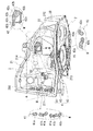
- FIG. 1A is a view of the transmission case as viewed from the converter housing side.
- FIG. 1B is an enlarged perspective view showing a region B of FIG. 1A.
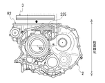
- FIG. 2 is a perspective view of the transmission case in FIG. 1A as viewed from the direction of the arrow II-II.
- FIG. 3A is a schematic view of a cut surface obtained by cutting the transmission case 2 in FIG. 2 at the surface A.
- FIG. 3B is a schematic view of a cross section of IIIb-IIIb in FIG. 3A.
- FIG. 4A is a diagram illustrating a process of assembling the control valve unit to the transmission case, and shows an assembling direction of the control valve unit.
- FIG. 4B is a view of the second seating portion seen from the communication hole.
- FIG. 5A is a diagram illustrating a process of assembling the control valve unit to the transmission case, and shows a state in which the second seating portion is viewed from the communication hole.
- FIG. 5B is a diagram
- FIGS. 1A and 1B are diagrams for explaining the transmission case 2.
- FIG. 1A is a view of the transmission case 2 as viewed from the converter housing side.
- FIG. 1B is an enlarged perspective view showing a region B of FIG. 1A.
- hatching is provided in the area where the communication hole 235 is provided for easy viewing.
- FIGS. 1A and 1B for convenience of explanation, the transmission case 2 is shown with the valve accommodating chamber R2 facing upward in the vertical line VL direction.
- the vertical direction means the upper and lower parts of the transmission case 2 of FIG. FIG.
- FIG. 2 is a diagram for explaining the transmission case 2, and is a perspective view of the transmission case 2 in FIG. 1A as viewed from the direction of arrow II-II.
- the control valve unit 3 is shown by a virtual line, and the mirror-finished region is hatched. Further, the positioning pin P is omitted.
- 3A and 3B are diagrams for explaining the transmission case 2.
- FIG. 3A is a schematic view of a cut surface obtained by cutting the transmission case 2 in FIG. 2 at the surface A.
- FIG. 3B is a schematic view of a cross section taken along the line AA in FIG. 3A.
- the seating portion 4 is exaggerated.
- the oil passages 35 and 35 of the control valve unit 3 and the oil passages 25 and 25 of the transmission case 2 are shown in cross section.
- the seating portion 5 is exaggerated.
- the transmission case 2 has an intermediate wall portion 23 in the internal space.
- the intermediate wall portion 23 intersects the rotation shaft X1 of the torque converter (not shown) of the continuously variable transmission 1.
- the outer peripheral edge of the intermediate wall portion 23 is surrounded by the outer peripheral wall 20 over the entire circumference.
- the space R1 surrounded by the intermediate wall portion 23 and the outer peripheral wall 20 in the transmission case 2 houses a forward / backward switching mechanism (not shown) and a final gear (not shown).
- valve containment chamber S3 As shown in FIG. 1A, a valve accommodating chamber R2 is provided on the upper side of the transmission case 2 in the vertical VL direction.
- the valve accommodation chamber R2 accommodates the control valve unit 3 (see the virtual line in FIG. 2), which will be described later.
- the valve accommodating chamber R2 is a region surrounded by a peripheral wall portion 21 extending upward from the outer peripheral wall 20 in the vertical VL direction. As shown in FIG. 2, the valve accommodating chamber R2 has an opening 250 that opens upward in the vertical VL direction. Of the outer peripheral wall 20, the area surrounded by the peripheral wall portion 21 is the bottom wall portion 22 of the valve accommodating chamber R2. The bottom wall portion 22 intersects the vertical straight line VL and has a concave shape recessed in the direction away from the opening 250 in the vertical straight line VL direction (see FIG. 3A).
- a part of the valve accommodating chamber R2 overlaps with the space R1 when viewed from the direction of the rotation axis X1.
- a through hole 235 is formed in a region where the valve accommodating chamber R2 and the space R1 overlap.
- the through hole 235 penetrates the intermediate wall portion 23 in the direction of the rotation axis X1 and communicates with the space R1 and the valve accommodating chamber R2 (in the following description, the through hole 235 is referred to as the communication hole 235).
- the communication hole 235 opens in a direction (rotation axis X1 direction) orthogonal to the opening direction (vertical line VL direction) of the opening 250.
- the communication hole 235 has an opening area that allows an operator to look into the valve accommodating chamber R2 side from the direction of the rotation axis X1.
- the peripheral wall portion 21 is composed of short wall portions 211 and 212 along the rotation axis X1 direction and long wall portions 213 and 214 connecting the ends of these short wall portions 211 and 212. There is.
- the short wall portions 211 and 212 and the long wall portions 213 and 214 are provided so as to surround the opening 250.
- the valve accommodating chamber R2 is provided with a seating portion 4 on which the control valve unit 3 described later is seated.
- the seating portion 4 extends upward in the vertical VL direction from the bottom wall portion 22 of the valve accommodating chamber R2.
- the seating portion 4 includes a first seating portion 41 provided near the short wall portion 211, a second seating portion 42 provided near the long wall portion 214, and a second seating portion 42 provided near the long wall portion 213. It is composed of three seating portions 43, and supports the control valve unit 3 at three locations (see FIG. 2).
- the seating surfaces 41a, 42a, and 43a of the first seating portion 41, the second seating portion 42, and the third seating portion 43, respectively, are flat surfaces orthogonal to the vertical VL direction.
- the seating surfaces 41a, 42a, and 43a are mirror-finished over the entire surface (see the hatched portion in FIG. 2.
- the mirror-finished region is also referred to as a mirror surface portion M).
- the conventional seating surface is formed by milling so as to have a predetermined flatness.
- milling is not required. This is because a seating surface having a higher flatness than the milling surface can be obtained by performing the mirror surface processing. It is not necessary to mirror-process all of the seating surfaces 41a, 42a, and 43a. Details will be described later, but at least the seating surface 42a may be mirror-finished.
- Bolt holes 41b, 42b, 43b are opened in the seating surfaces 41a, 42a, and 43a, respectively.
- a plurality of these bolt holes 41b, 42b, 43b are provided along the outer shape of the control valve unit 3.
- a part of the third seating portion 43 and the second seating portion 42 are provided in an area overlapping the communication hole 235 when viewed from the direction of the rotation axis X1.
- the seating surface 42a of the second seating portion 42 is located below the upper edge 235a of the communication hole 235 in the vertical line VL direction (see FIGS. 1A and 1B).
- a pin hole 42c is opened in the seating surface 42a of the second seating portion 42 in addition to the bolt hole 42b.
- a positioning pin P is inserted into the pin hole 42c.
- the positioning pin P is inserted into the pin hole 42c so that the center line C1 of the positioning pin P is parallel to the vertical line VL.
- Oil passages 25 and 25 are provided in the bottom wall portion 22 of the valve accommodating chamber R2 (see FIG. 2). As shown in FIG. 3A, the oil passages 25 and 25 extend in the vertical VL direction away from the bottom wall portion 22. The oil passages 25 and 25 communicate with an oil chamber (not shown) in the transmission case 2. Sealing materials Ca and Ca are internally fitted in the oil passages 25 and 25, respectively. These sealing materials Ca and Ca project upward from the tips 25a and 25a of the oil passages 25 and 25.
- Control valve unit 3 The control valve unit 3 has an outer shape that substantially matches the opening shape of the opening 250 of the valve accommodating chamber R2 (see FIG. 2).
- the control valve unit 3 is supported so as to straddle the first seating portion 41, the second seating portion 42, and the third seating portion 43.
- the control valve unit 3 is provided across the upper side of the oil passages 25 and 25 in a direction orthogonal to the vertical line VL (see FIG. 3A).
- control valve unit 3 is configured by superimposing the upper valve 31 and the lower valve 32.
- a separate plate (not shown) is provided between the upper valve 31 and the lower valve 32.
- An oil passage (not shown) is formed inside each of the upper valve 31 and the lower valve 32, and the upper valve 31 and the lower valve 32 form a hydraulic control circuit together with a separate plate.
- the control valve unit 3 is housed in the valve accommodating chamber R2 with the upper valve 31 facing downward with the overlapping direction of the upper valve 31 and the lower valve 32 along the vertical VL direction.
- the lower surface 310 of the upper valve 31 is seated on the seating portion 4. In this state, the lower surface 310 faces the bottom wall portion 22 at intervals in the vertical VL direction.
- the lower surface 310 of the upper valve 31 has a seating portion that faces the seating portion 4 (first seating portion 41, second seating portion 42, third seating portion 43) in the vertical VL direction. 5 (first seating portion 51, second seating portion 52, third seating portion 53) is provided.
- the seating portion 5 slightly protrudes from the lower surface 310 of the upper valve 31.
- the seating surfaces 51a, 52a, and 53a of the first seating portion 51, the second seating portion 52, and the third seating portion 53 are flat surfaces orthogonal to the vertical VL direction.
- through holes 51b, 52b, and 53b are opened in the seating surfaces 51a, 52a, and 53a, respectively. These through holes 51b, 52b, 53b are provided at positions corresponding to the bolt holes 41b, 42b, 43b described above.
- the through holes 51b, 52b, and 53b penetrate the control valve unit 3 in the vertical VL direction (see FIG. 3A).
- the seating surface 52a of the second seating portion 52 has a fitting hole 52c into which the positioning pin P is fitted. It is open (see FIGS. 3A and 3B).
- oil passages 35 and 35 are provided on the lower surface 310 of the upper valve 31.
- the oil passages 35 and 35 are connected to the flood control circuit in the control valve unit 3.
- the oil passages 35 and 35 extend downward in the vertical VL direction.
- the oil passages 35 and 35 are provided at positions corresponding to the oil passages 25 and 25 extending from the bottom wall portion 22 in the vertical VL direction.
- the control valve unit 3 has a seating portion by inserting a bolt B into the through holes 51b, 52b, 53b and screwing the bolt B into the bolt holes 41b, 42b, 43b of the seating portion 4. It is fixed at 4. In this state, the center line of the fitting hole 52c coincides with the center line C1 of the positioning pin P.
- the oil passages 35 and 35 are connected to the oil passages 25 and 25 described above via sealing materials Ca and Ca, respectively.
- [Assembly] 4A and 4B are diagrams illustrating a process of assembling the control valve unit 3 to the transmission case 2.
- FIG. 4A is a diagram showing an assembly direction of the control valve unit 3.
- FIG. 4B is a view of the second seating portion 42 seen from the communication hole 235.
- 5A and 5B are diagrams illustrating a process of assembling the control valve unit 3 to the transmission case 2.
- FIG. 5A is a diagram showing a state in which the second seating portion 42 is viewed from the communication hole 235.
- FIG. 5B is a diagram illustrating a seating process of the control valve unit 3.
- the operator inserts the control valve unit 3 from the opening 250 along the vertical VL direction while holding the control valve unit 3 with both hands, and accommodates the control valve unit 3 in the valve accommodating chamber R2. (In the figure, in the direction of the arrow).
- the operator first fits the fitting hole 52c (see FIG. 5A) of the second seating portion 52 of the control valve unit 3 into the positioning pin P.
- the fitting hole 52c is located in the blind spot of the operator. Further, as described above, the control valve unit 3 has an outer shape that substantially matches the shape of the opening 250 (see FIG. 2). Therefore, the operator cannot visually recognize the fitting hole 52c from the gap between the peripheral wall portion 21 and the control valve unit 3 in the opening 250. That is, the fitting hole 52c cannot be visually recognized from the opening 250 side.
- the operator can see the seating surface 42a of the second seating portion 42 of the valve accommodating chamber R2 from the space R1 side in the direction of the rotation axis X1 through the communication hole 235 (see FIG. 4B). Since the seating surface 42a is also a mirror surface portion M that has been mirror-finished, when the control valve unit 3 is brought close to the seating portion 4, the second seating portion 52 (fitting hole 52c) on the control valve unit 3 side is seated. It is reflected on the surface 42a (mirror surface portion M). The operator can visually recognize the mirror image 52c'(see FIG. 5A) of the fitting hole 52c reflected in the mirror surface portion M from the communication hole 235.
- the center line C2 of the fitting hole 52c may deviate from the center line C1 of the positioning pin P.
- the operator can grasp that the fitting hole 52c is deviated from the positioning pin P by visually recognizing the mirror image 52c'.
- the operator can fit the positioning pin P into the fitting hole 52c by moving the center line C2 of the fitting hole 52c in the direction corresponding to the center line C1 of the positioning pin P while looking at the mirror image 52c'. ..
- the oil passages 35 and 35 of the control valve unit 3 are the sealing materials Ca and Ca of the oil passages 25 and 25 and the vertical VL. They face each other with a predetermined interval CL1 in the direction. Further, the seating portion 5 of the control valve unit 3 faces the seating portion 4 of the transmission case 2 with a predetermined interval CL2 in the vertical VL direction. In this case, the distance CL1 between the oil passage 35 and the sealing material Ca is shorter than the distance CL2 between the seating portion 5 (seat surfaces 51a, 52a, 53a) and the seating portion 4 (seat surfaces 41a, 42a, 43a). (CL1 ⁇ CL2).
- control valve unit 3 can rotate around the center line C1.
- the control valve unit 3 since the control valve unit 3 has an outer shape that substantially matches the shape of the opening 250, the seating position does not deviate significantly in the circumferential direction around the center line C1.
- the bolt B is inserted into the through holes 51b, 52b, 53b and screwed into the bolt holes 41b, 42b, 43b, respectively, to fix the control valve unit 3 to the seating portion 4, thereby fixing the control valve unit 3 to the seating portion 4.
- the accommodation of 3 in the valve accommodation chamber R2 is completed (see FIG. 3A).
- the transmission case 2 has the following configuration.
- the transmission case 2 has a valve accommodating chamber R2 (storage area) of the control valve unit 3 (assembling member) inside.
- An opening 250 (first opening) is opened in the valve accommodating chamber R2.
- the valve accommodating chamber R2 is provided with a seating portion 4 on which the control valve unit 3 inserted from the opening direction of the opening 250 is seated.
- a mirror surface portion M that makes the seating portion 5 (the portion facing the seating portion 4) of the control valve unit 3 visible when the control valve unit 3 is inserted into the valve accommodating chamber R2 from the opening direction of the opening 250. Is provided.
- the control valve unit 3 can be assembled to the transmission case 2 without lowering the work efficiency.
- the transmission case 2 has the following configuration.
- the valve accommodating chamber R2 further has a communication hole 235 (second opening) that opens in the rotation axis X1 direction that intersects the opening direction of the opening 250.
- the mirror surface portion M is provided on the seating surface 42a of the second seating portion 42 provided in the region overlapping the communication hole 235.
- the seating portion 5 projected on the seating surface 42a can be visually recognized from the communication hole 235. Therefore, even if the seating portion 5 is located in the blind spot of the operator when viewed from the opening direction of the opening 250 and the seating portion 5 cannot be seen from the opening 250, the control is performed without lowering the work efficiency.
- the valve unit 3 can be assembled to the transmission case 2. Further, by performing mirror processing on the seating surface 42a of the second seating portion 42, a seating surface 42a having a higher flatness than the conventional milling processing can be obtained. Therefore, the conventional milling can be omitted, and the process can be integrated.
- the transmission case 2 has the following configuration. (3) A positioning pin P is provided on the second seating portion 42. The second seating portion 52 of the control valve unit 3 is formed with a fitting hole 52c that fits into the positioning pin P.
- the operator can know the positional relationship between the fitting hole 52c and the positioning pin P from the mirror image 52c'of the fitting hole 52c reflected on the mirror surface portion M, so that the positioning pin P is placed in the fitting hole 52c. Can be fitted.
- the positioning pin P provided only on the second seating portion 42 is illustrated, but the present invention is not limited to this.
- the positioning pin P may be provided on the first seating portion 41 and the third seating portion 43 in addition to the second seating portion 42.
- the control valve unit 3 can be positioned in the circumferential direction around the center line C1.
- the case where the seating surface 42a of the second seating portion 42 is a mirror surface portion M has been illustrated, but the present invention is not limited to this.
- Any region of the valve accommodating chamber R2 may be a mirror surface portion M as long as the operator can see it from the communication hole 235.
- the side surface (long wall portion 214: see FIG. 2) opposite to the communication hole 235 sandwiching the second seating portion 42 in the direction of the rotation axis X1 may be the mirror surface portion M.
- the assembly of the control valve unit 3 to the transmission case 2 is illustrated, but the present invention is not limited to this.
- a mirror surface portion M for reflecting the seating surface of the ATCU may be provided in the oil pump accommodating chamber.
- the invention according to the present embodiment is not limited to the above-described embodiment, and includes various changes and improvements that can be made within the scope of the technical idea.
Landscapes
- Engineering & Computer Science (AREA)
- General Engineering & Computer Science (AREA)
- Mechanical Engineering (AREA)
- Control Of Transmission Device (AREA)
- General Details Of Gearings (AREA)
Abstract
変速機ケースは、コントロールバルブユニットのバルブ収容室を内部に有する。変速機ケースは、バルブ収容室に開口する開口部と、バルブ収容室に設けられていると共に、開口部の開口方向から挿入されたコントロールバルブユニットが着座する着座部と、コントロールバルブユニットが開口部の開口方向から挿入された際に、コントロールバルブユニットの着座部を視認可能にする鏡面部と、有する。
Description
本発明は、変速機ケースに関する。
JP10-227352Aには、変速機ケースの所定位置に組み付けられるコントロールバルブアッシーが開示されている。
コントロールバルブアッシーの変速機ケースへの組み付けは、コントロールバルブアッシーを変速機ケースの所定位置に着座させることで行われる。
作業者は、コントロールバルブアッシーを両手で把持した状態で、目視により所定位置に着座させる。
しかしながら、変速機ケースやコントロールバルブアッシーの形状によっては、着座部分が作業者の死角に位置することがある。作業者は目視ができない状況で作業をすることになり、作業効率が低下する。
作業者は、コントロールバルブアッシーを両手で把持した状態で、目視により所定位置に着座させる。
しかしながら、変速機ケースやコントロールバルブアッシーの形状によっては、着座部分が作業者の死角に位置することがある。作業者は目視ができない状況で作業をすることになり、作業効率が低下する。
そこで、着座部分が作業者の死角に位置している状態でも、作業効率が低下しないようにすることが求められている。
本発明のある態様によれば、組付部材の格納領域を内部に有する変速機ケースは、前記格納領域に開口する第1開口部と、前記格納領域に設けられていると共に、前記第1開口部の開口方向から挿入された前記組付部材が着座する着座部と、前記組付部材が前記第1開口部に前記開口方向から挿入された際に、前記組付部材の前記着座部との対向部を視認可能にする鏡面部と、を有する。
上記態様によれば、着座部分が死角に位置している状態でも、作業効率が低下しないようにすることができる。
以下、本実施形態を、車両用の無段変速機1の変速機ケース2に適用した場合を例に挙げて説明する。
図1A、図1Bは、変速機ケース2を説明する図である。図1Aは、変速機ケース2をコンバータハウジング側からみた図である。図1Bは、図1AのB領域を拡大して示した斜視図である。
なお、図1Aでは、見易くするために、連通孔235が設けられた領域にハッチングを付してある。図1A、図1Bでは、説明の便宜上、変速機ケース2は、バルブ収容室R2を鉛直線VL方向上側に向けた状態で示してある。以下の説明では、上下方向とは、図1の変速機ケース2における上、下を意味するものとする。
図2は、変速機ケース2を説明する図であり、図1Aにおける変速機ケース2をII-II矢視方向から見た斜視図である。
なお、図2では、コントロールバルブユニット3を仮想線で示していると共に、鏡面加工が施された領域にハッチングを付してある。また、位置決めピンPは省略してある。
図3A、図3Bは、変速機ケース2を説明する図である。図3Aは、図2における変速機ケース2を面Aで切断した切断面の模式図である。図3Bは、図3AにおけるA-A断面の模式図である。
なお、図3Aでは、着座部4を誇張して示している。また、説明の便宜上、コントロールバルブユニット3の油路35、35と変速機ケース2の油路25、25を断面で示している。図3Bでは、着座部5を誇張して示している。
図1A、図1Bは、変速機ケース2を説明する図である。図1Aは、変速機ケース2をコンバータハウジング側からみた図である。図1Bは、図1AのB領域を拡大して示した斜視図である。
なお、図1Aでは、見易くするために、連通孔235が設けられた領域にハッチングを付してある。図1A、図1Bでは、説明の便宜上、変速機ケース2は、バルブ収容室R2を鉛直線VL方向上側に向けた状態で示してある。以下の説明では、上下方向とは、図1の変速機ケース2における上、下を意味するものとする。
図2は、変速機ケース2を説明する図であり、図1Aにおける変速機ケース2をII-II矢視方向から見た斜視図である。
なお、図2では、コントロールバルブユニット3を仮想線で示していると共に、鏡面加工が施された領域にハッチングを付してある。また、位置決めピンPは省略してある。
図3A、図3Bは、変速機ケース2を説明する図である。図3Aは、図2における変速機ケース2を面Aで切断した切断面の模式図である。図3Bは、図3AにおけるA-A断面の模式図である。
なお、図3Aでは、着座部4を誇張して示している。また、説明の便宜上、コントロールバルブユニット3の油路35、35と変速機ケース2の油路25、25を断面で示している。図3Bでは、着座部5を誇張して示している。
[変速機ケース2]
図1Aに示すように、変速機ケース2は、内部空間に中間壁部23を有している。中間壁部23は、無段変速機1のトルクコンバータ(図示せず)の回転軸X1と交差している。中間壁部23の外周縁は、全周に亘って外周壁20によって囲まれている。
図1Aに示すように、変速機ケース2は、内部空間に中間壁部23を有している。中間壁部23は、無段変速機1のトルクコンバータ(図示せず)の回転軸X1と交差している。中間壁部23の外周縁は、全周に亘って外周壁20によって囲まれている。
変速機ケース2における中間壁部23と外周壁20とで囲まれた空間R1には、前後進切替機構(図示せず)や、ファイナルギア(図示せず)が収容されている。
[バルブ収容室S3]
図1Aに示すように、鉛直線VL方向における変速機ケース2の上側には、バルブ収容室R2が設けられている。バルブ収容室R2には、後記するコントロールバルブユニット3(図2における仮想線参照)が収容される。
図1Aに示すように、鉛直線VL方向における変速機ケース2の上側には、バルブ収容室R2が設けられている。バルブ収容室R2には、後記するコントロールバルブユニット3(図2における仮想線参照)が収容される。
図1Aに示すように、バルブ収容室R2は、外周壁20から鉛直線VL方向上向きに延びる周壁部21で囲まれた領域である。
図2に示すように、バルブ収容室R2は、鉛直線VL方向上向きに開口した開口部250を有している。外周壁20のうち、周壁部21で囲まれた領域がバルブ収容室R2の底壁部22となっている。底壁部22は、鉛直線VLに交差していると共に、鉛直線VL方向における開口部250から離れる方向に窪んだ凹形状を成している(図3A参照)。
図2に示すように、バルブ収容室R2は、鉛直線VL方向上向きに開口した開口部250を有している。外周壁20のうち、周壁部21で囲まれた領域がバルブ収容室R2の底壁部22となっている。底壁部22は、鉛直線VLに交差していると共に、鉛直線VL方向における開口部250から離れる方向に窪んだ凹形状を成している(図3A参照)。
ここで、図1A、図1Bに示すように、回転軸X1方向から見て、バルブ収容室R2の一部は、空間R1とオーバーラップしている。中間壁部23は、バルブ収容室R2と空間R1とがオーバーラップする領域に貫通孔235が形成されている。
貫通孔235は、中間壁部23を回転軸X1方向に貫通しており、空間R1とバルブ収容室R2と連通している(以下の説明では、貫通孔235を連通孔235と標記する)。空間R1において、連通孔235は、開口部250の開口方向(鉛直線VL方向)と直交する方向(回転軸X1方向)に開口している。
なお、詳細は後記するが、連通孔235は、作業者が回転軸X1方向からバルブ収容室R2側を覗くことができる程度の開口面積を有している。
なお、詳細は後記するが、連通孔235は、作業者が回転軸X1方向からバルブ収容室R2側を覗くことができる程度の開口面積を有している。
図2に示すように、周壁部21は、回転軸X1方向に沿う短壁部211、212と、これら短壁部211、212の端部同士を接続する長壁部213、214とから構成されている。これら短壁部211、212と長壁部213、214は、開口部250を囲むように設けられている。
図2、図3Aに示すように、バルブ収容室R2には、後記するコントロールバルブユニット3が着座する着座部4が設けられている。着座部4は、バルブ収容室R2の底壁部22から鉛直線VL方向上向きに延びている。
本実施形態では、着座部4は、短壁部211近傍に設けられた第1着座部41と、長壁部214近傍に設けられた第2着座部42と、長壁部213近傍に設けられた第3着座部43と、から構成されており、3カ所でコントロールバルブユニット3を支持するようになっている(図2参照)。
第1着座部41、第2着座部42、第3着座部43のそれぞれ着座面41a、42a、43aは、鉛直線VL方向に直交する平坦面である。
着座面41a、42a、43aは、全面に亘って鏡面加工が施されている(図2におけるハッチング部参照。以下、鏡面加工が施された領域を鏡面部Mとも表記する)。
ここで、従来の着座面は、フライス加工によって所定の平面度を有するように形成される。本実施形態のように着座面に鏡面加工を施す場合、フライス加工は不要である。鏡面加工を施すことで、フライス加工よりも高い平面度の着座面が得られるからである。
なお、着座面41a、42a、43aの全てに鏡面加工をする必要はない。詳細は後記するが、少なくとも着座面42aが鏡面加工されていれば良い。
ここで、従来の着座面は、フライス加工によって所定の平面度を有するように形成される。本実施形態のように着座面に鏡面加工を施す場合、フライス加工は不要である。鏡面加工を施すことで、フライス加工よりも高い平面度の着座面が得られるからである。
なお、着座面41a、42a、43aの全てに鏡面加工をする必要はない。詳細は後記するが、少なくとも着座面42aが鏡面加工されていれば良い。
着座面41a、42a、43aには、ボルト穴41b、42b、43bがそれぞれ開口している。これらボルト穴41b、42b、43bは、コントロールバルブユニット3の外形に沿って複数個設けられている。
回転軸X1方向から見て、第3着座部43の一部と、第2着座部42は、連通孔235と重なる領域に設けられている。第2着座部42の着座面42aは、鉛直線VL方向における連通孔235の上縁235aよりも下側に位置している(図1A、図1B参照)。
図3Aに示すように、第2着座部42の着座面42aには、ボルト穴42bの他にピン穴42cが開口している。ピン穴42cには、位置決めピンPが挿入されている。位置決めピンPは、当該位置決めピンPの中心線C1が、鉛直線VLに平行になるようにピン穴42cに挿入されている。
バルブ収容室R2の底壁部22には油路25、25が設けられている(図2参照)。
図3Aに示すように、油路25、25は鉛直線VL方向で底壁部22から離れる方向に延びている。油路25、25は、変速機ケース2内の図示しない油室と連通している。油路25、25には、それぞれシール材Ca、Caが内嵌されている。これらシール材Ca、Caは、油路25、25の先端25a、25aよりも上側に突出している。
図3Aに示すように、油路25、25は鉛直線VL方向で底壁部22から離れる方向に延びている。油路25、25は、変速機ケース2内の図示しない油室と連通している。油路25、25には、それぞれシール材Ca、Caが内嵌されている。これらシール材Ca、Caは、油路25、25の先端25a、25aよりも上側に突出している。
[コントロールバルブユニット3]
コントロールバルブユニット3は、バルブ収容室R2の開口部250の開口形状と略整合する外形を有している(図2参照)。コントロールバルブユニット3は、第1着座部41と第2着座部42と第3着座部43とに跨って支持されている。コントロールバルブユニット3は、油路25、25の上側を鉛直線VLに直交する方向に横切って設けられている(図3A参照)。
コントロールバルブユニット3は、バルブ収容室R2の開口部250の開口形状と略整合する外形を有している(図2参照)。コントロールバルブユニット3は、第1着座部41と第2着座部42と第3着座部43とに跨って支持されている。コントロールバルブユニット3は、油路25、25の上側を鉛直線VLに直交する方向に横切って設けられている(図3A参照)。
図3Aに示すように、コントロールバルブユニット3は、アッパーバルブ31とロアバルブ32とを重ね合わせて構成されている。アッパーバルブ31とロアバルブ32との間にはセパレートプレート(図示せず)が設けられている。アッパーバルブ31とロアバルブ32は内部にそれぞれ油路(図示せず)が形成されており、セパレートプレートと合わせて油圧制御回路を構成している。
コントロールバルブユニット3は、アッパーバルブ31とロアバルブ32の重ね合わせ方向を鉛直線VL方向に沿わせた状態で、アッパーバルブ31を下向きにしてバルブ収容室R2に収容されている。前記した着座部4には、アッパーバルブ31の下面310が着座するようになっている。この状態において、下面310は、鉛直線VL方向で底壁部22と間隔を空けて対向している。
図3Bに示すように、アッパーバルブ31の下面310には、前記した着座部4(第1着座部41、第2着座部42、第3着座部43)と鉛直線VL方向で対向する着座部5(第1着座部51、第2着座部52、第3着座部53)が設けられている。着座部5は、アッパーバルブ31の下面310から僅かに突出している。
第1着座部51、第2着座部52、第3着座部53のそれぞれの着座面51a、52a、53aは、鉛直線VL方向に直交する平坦面となっている。
図3Bに示すように、着座面51a、52a、53aには、貫通孔51b、52b、53bがそれぞれ開口している。これら貫通孔51b、52b、53bは、前記したボルト穴41b、42b、43bに対応する位置に設けられている。貫通孔51b、52b、53bは、鉛直線VL方向でコントロールバルブユニット3を貫通している(図3A参照)。
ここで、鉛直線VL方向で第2着座部42に対向する第2着座部52において、当該第2着座部52の着座面52aには、前記した位置決めピンPが嵌合する嵌合穴52cが開口している(図3A、図3B参照)。
図3A、図3Bに示すように、アッパーバルブ31の下面310には、油路35、35が設けられている。油路35、35は、コントロールバルブユニット3内の油圧制御回路に接続されている。油路35、35は、鉛直線VL方向下向きに延びている。油路35、35は、鉛直線VL方向における底壁部22から延びる油路25、25に対応する位置に設けられている。
図3Aに示すように、コントロールバルブユニット3は、貫通孔51b、52b、53bにボルトBを挿入すると共に、ボルトBを着座部4のボルト穴41b、42b、43bに螺入することで着座部4に固定されている。この状態において、嵌合穴52cの中心線は、位置決めピンPの中心線C1と一致している。油路35、35は、シール材Ca、Caを介して前記した油路25、25とそれぞれ接続している。
[組み付け]
図4A、図4Bは、コントロールバルブユニット3を変速機ケース2へ組み付ける過程を説明する図である。図4Aは、コントロールバルブユニット3の組み付け方向を示す図である。図4Bは、連通孔235から第2着座部42を見た図である。
図5A、図5Bは、コントロールバルブユニット3を変速機ケース2へ組み付ける過程を説明する図である。図5Aは、連通孔235から第2着座部42を覗いた状態を示す図である。図5Bは、コントロールバルブユニット3の着座過程を説明する図である。
図4A、図4Bは、コントロールバルブユニット3を変速機ケース2へ組み付ける過程を説明する図である。図4Aは、コントロールバルブユニット3の組み付け方向を示す図である。図4Bは、連通孔235から第2着座部42を見た図である。
図5A、図5Bは、コントロールバルブユニット3を変速機ケース2へ組み付ける過程を説明する図である。図5Aは、連通孔235から第2着座部42を覗いた状態を示す図である。図5Bは、コントロールバルブユニット3の着座過程を説明する図である。
図4Aに示すように、作業者は、コントロールバルブユニット3を両手で把持した状態で、コントロールバルブユニット3を鉛直線VL方向に沿って開口部250から挿入して、バルブ収容室R2に収容する(図中、矢印方向)。
作業者は、まずコントロールバルブユニット3の第2着座部52の嵌合穴52c(図5A参照)を、位置決めピンPに嵌合させる。
ここで、コントロールバルブユニット3を鉛直線VL方向上側から見ると、嵌合穴52cは、作業者の死角に位置している。また、前記した通り、コントロールバルブユニット3は開口部250の形状と略整合する外形を有している(図2参照)。
従って、作業者は、開口部250における周壁部21とコントロールバルブユニット3の隙間などから嵌合穴52cを視認することはできない。つまり、開口部250側からは嵌合穴52cを視認することはできない。
従って、作業者は、開口部250における周壁部21とコントロールバルブユニット3の隙間などから嵌合穴52cを視認することはできない。つまり、開口部250側からは嵌合穴52cを視認することはできない。
作業者は、連通孔235を通して、回転軸X1方向における空間R1側からバルブ収容室R2の第2着座部42の着座面42aを覗くことができる(図4B参照)。
着座面42aは鏡面加工が施された鏡面部Mでもあるため、コントロールバルブユニット3を着座部4に接近させると、コントロールバルブユニット3側の第2着座部52(嵌合穴52c)が、着座面42a(鏡面部M)に映る。
作業者は、連通孔235から鏡面部Mに映った嵌合穴52cの鏡像52c'(図5A参照)を視認することができる。
着座面42aは鏡面加工が施された鏡面部Mでもあるため、コントロールバルブユニット3を着座部4に接近させると、コントロールバルブユニット3側の第2着座部52(嵌合穴52c)が、着座面42a(鏡面部M)に映る。
作業者は、連通孔235から鏡面部Mに映った嵌合穴52cの鏡像52c'(図5A参照)を視認することができる。
例えば、図5Aに示すように、コントロールバルブユニット3を着座部4に接近させた際、嵌合穴52cの中心線C2が、位置決めピンPの中心線C1からずれることがある。この場合において、作業者は鏡像52c'を視認することで、嵌合穴52cが位置決めピンPからずれていることを把握できる。
作業者は、鏡像52c'を見ながら、嵌合穴52cの中心線C2が位置決めピンPの中心線C1に一致する方向に動かして、嵌合穴52cに位置決めピンPを嵌合させることができる。
図5Bに示すように、嵌合穴52cに位置決めピンPを嵌合させた状態において、コントロールバルブユニット3の油路35、35は、油路25、25のシール材Ca、Caと鉛直線VL方向で所定間隔CL1を空けてそれぞれ対向している。また、コントロールバルブユニット3の着座部5は、変速機ケース2の着座部4と鉛直線VL方向で所定間隔CL2を空けて対向している。
この場合において、油路35とシール材Caとの間隔CL1は、着座部5(着座面51a、52a、53a)と着座部4(着座面41a、42a、43a)との間隔CL2よりも短くなるように設定されている(CL1<CL2)。
この場合において、油路35とシール材Caとの間隔CL1は、着座部5(着座面51a、52a、53a)と着座部4(着座面41a、42a、43a)との間隔CL2よりも短くなるように設定されている(CL1<CL2)。
この状態において、コントロールバルブユニット3は、中心線C1回りに回転可能である。しかしながら、前記した通りコントロールバルブユニット3は、開口部250の形状と略整合する外形を有しているため、中心線C1周りの周方向で大きく着座位置がずれることはない。
嵌合穴52cを位置決めピンPに嵌合させた状態で、さらにコントロールバルブユニット3を下側に移動させると、コントロールバルブユニット3の油路35、35が、シール材Ca、Caを介して油路25、25とそれぞれ接続される。そのあと、着座部5(着座面51a、52a、53a)と、着座部4(着座面41a、42a、43a)とがそれぞれ当接して着座が完了する。
着座完了後に、ボルトBを貫通孔51b、52b、53bに挿入すると共に、ボルト穴41b、42b、43bにそれぞれ螺入して、コントロールバルブユニット3を着座部4に固定することで、コントロールバルブユニット3のバルブ収容室R2への収容は完了する(図3A参照)。
本実施形態にかかる変速機ケース2は、以下の構成を有している。
(1)変速機ケース2は、コントロールバルブユニット3(組付部材)のバルブ収容室R2(格納領域)を内部に有する。
バルブ収容室R2には、開口部250(第1開口部)が開口している。
バルブ収容室R2には、開口部250の開口方向から挿入されたコントロールバルブユニット3が着座する着座部4が設けられている。
バルブ収容室R2には、コントロールバルブユニット3が開口部250の開口方向から挿入された際に、コントロールバルブユニット3の着座部5(着座部4との対向部)を視認可能にする鏡面部Mが設けられている。
(1)変速機ケース2は、コントロールバルブユニット3(組付部材)のバルブ収容室R2(格納領域)を内部に有する。
バルブ収容室R2には、開口部250(第1開口部)が開口している。
バルブ収容室R2には、開口部250の開口方向から挿入されたコントロールバルブユニット3が着座する着座部4が設けられている。
バルブ収容室R2には、コントロールバルブユニット3が開口部250の開口方向から挿入された際に、コントロールバルブユニット3の着座部5(着座部4との対向部)を視認可能にする鏡面部Mが設けられている。
このように構成すると、着座部5が作業者の死角に位置している状態でも、作業者は鏡面部Mに映し出された着座部5を視認しながら作業ができる。
よって、作業効率を低下させることなくコントロールバルブユニット3を変速機ケース2に組み付けることができる。
よって、作業効率を低下させることなくコントロールバルブユニット3を変速機ケース2に組み付けることができる。
本実施形態にかかる変速機ケース2は、以下の構成を有している。
(2)バルブ収容室R2は、開口部250の開口方向と交差する回転軸X1方向に開口する連通孔235(第2開口部)をさらに有している。
連通孔235の開口方向から見て、鏡面部Mは連通孔235と重なる領域に設けられた第2着座部42の着座面42aに設けられている。
(2)バルブ収容室R2は、開口部250の開口方向と交差する回転軸X1方向に開口する連通孔235(第2開口部)をさらに有している。
連通孔235の開口方向から見て、鏡面部Mは連通孔235と重なる領域に設けられた第2着座部42の着座面42aに設けられている。
このように構成すると、着座面42aに映し出された着座部5を連通孔235から視認できる。よって、開口部250の開口方向から見たときに、着座部5が作業者の死角に位置し、さらに開口部250から着座部5を見ることができない場合でも、作業効率を低下させることなくコントロールバルブユニット3を変速機ケース2に組み付けることができる。
また、第2着座部42の着座面42aに鏡面加工を施すことで、従来のフライス加工よりも平面度の高い着座面42aが得られる。よって、従来のフライス加工を省略することができるので、工程集約が可能になる。
また、第2着座部42の着座面42aに鏡面加工を施すことで、従来のフライス加工よりも平面度の高い着座面42aが得られる。よって、従来のフライス加工を省略することができるので、工程集約が可能になる。
本実施形態にかかる変速機ケース2は、以下の構成を有している。
(3)第2着座部42には、位置決めピンPが設けられている。
コントロールバルブユニット3の第2着座部52には位置決めピンPに嵌合する嵌合穴52cが形成されている。
(3)第2着座部42には、位置決めピンPが設けられている。
コントロールバルブユニット3の第2着座部52には位置決めピンPに嵌合する嵌合穴52cが形成されている。
このように構成すると、作業者は、鏡面部Mに映った嵌合穴52cの鏡像52c'から、嵌合穴52cと位置決めピンPの位置関係がわかるので、嵌合穴52cに位置決めピンPを嵌合させることができる。
本実施形態では、位置決めピンPが第2着座部42にのみ設けられたものを例示したが、これに限定されない。位置決めピンPは、第2着座部42の他に第1着座部41、第3着座部43に設けられていても良い。これにより、中心線C1周りの周方向におけるコントロールバルブユニット3の位置決めをすることができる。
また、第2着座部42の着座面42aを鏡面部Mにした場合を例示したが、これに限定されない。作業者が連通孔235から視認できる範囲であれば、バルブ収容室R2の任意の領域を鏡面部Mにしても良い。例えば周壁部21において、回転軸X1方向における第2着座部42を挟んだ連通孔235と反対の側面(長壁部214:図2参照)を鏡面部Mにしても良い。
また、第2着座部42の着座面42aを鏡面部Mにした場合を例示したが、これに限定されない。作業者が連通孔235から視認できる範囲であれば、バルブ収容室R2の任意の領域を鏡面部Mにしても良い。例えば周壁部21において、回転軸X1方向における第2着座部42を挟んだ連通孔235と反対の側面(長壁部214:図2参照)を鏡面部Mにしても良い。
本実施形態では、コントロールバルブユニット3の変速機ケース2への組み付けを例示したが、これに限定されない。例えば、ATCUを変速機ケース2のオイルポンプ収容室に組み付ける場合において、当該オイルポンプ収容室にATCUの着座面を映す鏡面部Mを設けても良い。
本実施形態にかかる発明は、上記した実施形態に限定されるものではなく、その技術的思想の範囲内でなしうる様々な変更、改良が含まれる。
本願は、2019年11月11日付けで日本国特許庁に出願した特願2019-204205号に基づく優先権を主張し、その出願の全ての内容は、参照により本明細書に組み込まれる。
Claims (5)
- 組付部材の格納領域を内部に有する変速機ケースであって、
前記格納領域に開口する第1開口部と、
前記格納領域に設けられていると共に、前記第1開口部の開口方向から挿入された前記組付部材が着座する着座部と、
前記組付部材が前記第1開口部に前記開口方向から挿入された際に、前記組付部材の前記着座部との対向部を視認可能にする鏡面部と、を有する変速機ケース。 - 前記格納領域は、前記第1開口部の前記開口方向と交差する方向に開口する第2開口部をさらに有しており、
前記第2開口部の開口方向から見て、前記鏡面部は前記第2開口部と重なる領域に設けられている請求項1に記載の変速機ケース。 - 前記鏡面部は、前記着座部の着座面に設けられている請求項2に記載の変速機ケース。
- 前記着座部には位置決めピンが設けられており、
前記対向部には前記位置決めピンが嵌合する嵌合穴が形成されている請求項1~3のいずれか1に記載の変速機ケース。 - 前記組付部材はコントロールバルブユニットであり、
前記格納領域は、変速機ケースのバルブ収容室である請求項1~4のいずれか1に記載の変速機ケース。
Priority Applications (3)
| Application Number | Priority Date | Filing Date | Title |
|---|---|---|---|
| CN202080066199.1A CN114423970B (zh) | 2019-11-11 | 2020-10-19 | 变速箱壳体 |
| US17/763,564 US11732798B2 (en) | 2019-11-11 | 2020-10-19 | Transmission case |
| JP2021555958A JP7219352B2 (ja) | 2019-11-11 | 2020-10-19 | 変速機ケース |
Applications Claiming Priority (2)
| Application Number | Priority Date | Filing Date | Title |
|---|---|---|---|
| JP2019204205 | 2019-11-11 | ||
| JP2019-204205 | 2019-11-11 |
Publications (1)
| Publication Number | Publication Date |
|---|---|
| WO2021095445A1 true WO2021095445A1 (ja) | 2021-05-20 |
Family
ID=75912009
Family Applications (1)
| Application Number | Title | Priority Date | Filing Date |
|---|---|---|---|
| PCT/JP2020/039219 Ceased WO2021095445A1 (ja) | 2019-11-11 | 2020-10-19 | 変速機ケース |
Country Status (4)
| Country | Link |
|---|---|
| US (1) | US11732798B2 (ja) |
| JP (1) | JP7219352B2 (ja) |
| CN (1) | CN114423970B (ja) |
| WO (1) | WO2021095445A1 (ja) |
Citations (2)
| Publication number | Priority date | Publication date | Assignee | Title |
|---|---|---|---|---|
| JPH0373754U (ja) * | 1989-11-22 | 1991-07-24 | ||
| JPH10227352A (ja) * | 1997-02-17 | 1998-08-25 | Jatco Corp | 自動変速機のコントロールバルブ装置 |
Family Cites Families (8)
| Publication number | Priority date | Publication date | Assignee | Title |
|---|---|---|---|---|
| US4854348A (en) * | 1986-08-06 | 1989-08-08 | Shigeo Tochikubo | Single cylinder type switching valve for mixing hot and cold waters |
| US4850669A (en) * | 1986-08-15 | 1989-07-25 | Welker Engineering Company | Explosion-proof optical fiber connector for a light source |
| JP2678261B2 (ja) * | 1989-08-12 | 1997-11-17 | 三田工業株式会社 | ソータ |
| JP5962620B2 (ja) * | 2013-09-13 | 2016-08-03 | 株式会社デンソー | アクチュエータの製造方法 |
| CN105414905B (zh) * | 2015-12-30 | 2018-05-18 | 鞠小平 | 一种智能电驱变速箱液压控制系统用阀体的加工方法 |
| WO2019163316A1 (ja) * | 2018-02-26 | 2019-08-29 | ジヤトコ株式会社 | 動力伝達装置 |
| CN110270960A (zh) * | 2019-07-01 | 2019-09-24 | 十堰超力达工贸有限公司 | 一种变速箱生产用装配平台 |
| JP7580882B2 (ja) * | 2020-08-24 | 2024-11-12 | ジヤトコ株式会社 | 減速機ケース |
-
2020
- 2020-10-19 CN CN202080066199.1A patent/CN114423970B/zh active Active
- 2020-10-19 WO PCT/JP2020/039219 patent/WO2021095445A1/ja not_active Ceased
- 2020-10-19 JP JP2021555958A patent/JP7219352B2/ja active Active
- 2020-10-19 US US17/763,564 patent/US11732798B2/en active Active
Patent Citations (2)
| Publication number | Priority date | Publication date | Assignee | Title |
|---|---|---|---|---|
| JPH0373754U (ja) * | 1989-11-22 | 1991-07-24 | ||
| JPH10227352A (ja) * | 1997-02-17 | 1998-08-25 | Jatco Corp | 自動変速機のコントロールバルブ装置 |
Also Published As
| Publication number | Publication date |
|---|---|
| JPWO2021095445A1 (ja) | 2021-05-20 |
| CN114423970A (zh) | 2022-04-29 |
| CN114423970B (zh) | 2023-10-03 |
| JP7219352B2 (ja) | 2023-02-07 |
| US20220341491A1 (en) | 2022-10-27 |
| US11732798B2 (en) | 2023-08-22 |
Similar Documents
| Publication | Publication Date | Title |
|---|---|---|
| JP7289989B2 (ja) | 加工機械 | |
| CN109196257B (zh) | 阀装置 | |
| JPWO2002046583A1 (ja) | オイルコントロールバルブ及びその取付け方法 | |
| US10415682B2 (en) | Differential case | |
| WO2021095445A1 (ja) | 変速機ケース | |
| JP7580900B2 (ja) | 動力伝達装置 | |
| JPWO2019176329A1 (ja) | 動力伝達装置およびその製造方法 | |
| EP1508644B1 (en) | Construction machine and method for manufacturing the same | |
| KR102835367B1 (ko) | 기어 기구, 감속기, 및 감속기를 사용하는 구동 장치 | |
| JP2014190444A (ja) | 変速機 | |
| JP3994926B2 (ja) | スタータ取付構造 | |
| JP2010187529A (ja) | モータアクチュエータ | |
| KR102437290B1 (ko) | 차량용 냉각수 제어밸브의 액츄에이터 | |
| JP3473368B2 (ja) | 回転位相差可変機構 | |
| JP4784114B2 (ja) | 遊星歯車装置 | |
| JP2006046083A (ja) | 樹脂製シリンダヘッドカバー | |
| JP7398217B2 (ja) | 歯車機構、減速機、および、その減速機を用いる駆動装置 | |
| JP2015048779A (ja) | シリンダヘッド | |
| KR101150421B1 (ko) | 공작 기계용 툴 터렛의 홀더 설치 구조 및 이에 적용되는 블럭형 탄성 위치 결정소자 | |
| JP2017002854A (ja) | エンジンの潤滑油供給機構 | |
| JP2006138285A (ja) | ポンプ装置 | |
| JP4493577B2 (ja) | 車輌用灯具 | |
| JP2007276083A (ja) | ピンミラーカッタ及び刃先交換チップ | |
| JPH07332497A (ja) | シール装置 | |
| JP2002172448A (ja) | 積層カム |
Legal Events
| Date | Code | Title | Description |
|---|---|---|---|
| 121 | Ep: the epo has been informed by wipo that ep was designated in this application |
Ref document number: 20886200 Country of ref document: EP Kind code of ref document: A1 |
|
| ENP | Entry into the national phase |
Ref document number: 2021555958 Country of ref document: JP Kind code of ref document: A |
|
| NENP | Non-entry into the national phase |
Ref country code: DE |
|
| 122 | Ep: pct application non-entry in european phase |
Ref document number: 20886200 Country of ref document: EP Kind code of ref document: A1 |