WO2021095365A1 - 部品充填装置及び部品充填方法 - Google Patents
部品充填装置及び部品充填方法 Download PDFInfo
- Publication number
- WO2021095365A1 WO2021095365A1 PCT/JP2020/035717 JP2020035717W WO2021095365A1 WO 2021095365 A1 WO2021095365 A1 WO 2021095365A1 JP 2020035717 W JP2020035717 W JP 2020035717W WO 2021095365 A1 WO2021095365 A1 WO 2021095365A1
- Authority
- WO
- WIPO (PCT)
- Prior art keywords
- component
- stud
- hole
- cylinder
- parts
- Prior art date
- Legal status (The legal status is an assumption and is not a legal conclusion. Google has not performed a legal analysis and makes no representation as to the accuracy of the status listed.)
- Ceased
Links
Images




Classifications
-
- B—PERFORMING OPERATIONS; TRANSPORTING
- B23—MACHINE TOOLS; METAL-WORKING NOT OTHERWISE PROVIDED FOR
- B23K—SOLDERING OR UNSOLDERING; WELDING; CLADDING OR PLATING BY SOLDERING OR WELDING; CUTTING BY APPLYING HEAT LOCALLY, e.g. FLAME CUTTING; WORKING BY LASER BEAM
- B23K9/00—Arc welding or cutting
- B23K9/20—Stud welding
- B23K9/206—Stud welding with automatic stud supply
-
- B—PERFORMING OPERATIONS; TRANSPORTING
- B23—MACHINE TOOLS; METAL-WORKING NOT OTHERWISE PROVIDED FOR
- B23K—SOLDERING OR UNSOLDERING; WELDING; CLADDING OR PLATING BY SOLDERING OR WELDING; CUTTING BY APPLYING HEAT LOCALLY, e.g. FLAME CUTTING; WORKING BY LASER BEAM
- B23K11/00—Resistance welding; Severing by resistance heating
- B23K11/002—Resistance welding; Severing by resistance heating specially adapted for particular articles or work
- B23K11/004—Welding of a small piece to a large or broad piece
- B23K11/0046—Welding of a small piece to a large or broad piece the extremity of a small piece being welded to a base, e.g. cooling studs or fins to tubes or plates
- B23K11/0053—Stud welding, i.e. resistive
-
- B—PERFORMING OPERATIONS; TRANSPORTING
- B23—MACHINE TOOLS; METAL-WORKING NOT OTHERWISE PROVIDED FOR
- B23K—SOLDERING OR UNSOLDERING; WELDING; CLADDING OR PLATING BY SOLDERING OR WELDING; CUTTING BY APPLYING HEAT LOCALLY, e.g. FLAME CUTTING; WORKING BY LASER BEAM
- B23K11/00—Resistance welding; Severing by resistance heating
- B23K11/36—Auxiliary equipment
-
- B—PERFORMING OPERATIONS; TRANSPORTING
- B23—MACHINE TOOLS; METAL-WORKING NOT OTHERWISE PROVIDED FOR
- B23P—METAL-WORKING NOT OTHERWISE PROVIDED FOR; COMBINED OPERATIONS; UNIVERSAL MACHINE TOOLS
- B23P19/00—Machines for simply fitting together or separating metal parts or objects, or metal and non-metal parts, whether or not involving some deformation; Tools or devices therefor so far as not provided for in other classes
- B23P19/001—Article feeders for assembling machines
- B23P19/004—Feeding the articles from hoppers to machines or dispensers
- B23P19/005—Feeding the articles from hoppers to machines or dispensers by using flowing gases
-
- B—PERFORMING OPERATIONS; TRANSPORTING
- B65—CONVEYING; PACKING; STORING; HANDLING THIN OR FILAMENTARY MATERIAL
- B65G—TRANSPORT OR STORAGE DEVICES, e.g. CONVEYORS FOR LOADING OR TIPPING, SHOP CONVEYOR SYSTEMS OR PNEUMATIC TUBE CONVEYORS
- B65G47/00—Article or material-handling devices associated with conveyors; Methods employing such devices
- B65G47/02—Devices for feeding articles or materials to conveyors
- B65G47/04—Devices for feeding articles or materials to conveyors for feeding articles
-
- B—PERFORMING OPERATIONS; TRANSPORTING
- B65—CONVEYING; PACKING; STORING; HANDLING THIN OR FILAMENTARY MATERIAL
- B65G—TRANSPORT OR STORAGE DEVICES, e.g. CONVEYORS FOR LOADING OR TIPPING, SHOP CONVEYOR SYSTEMS OR PNEUMATIC TUBE CONVEYORS
- B65G47/00—Article or material-handling devices associated with conveyors; Methods employing such devices
- B65G47/74—Feeding, transfer, or discharging devices of particular kinds or types
- B65G47/88—Separating or stopping elements, e.g. fingers
-
- B—PERFORMING OPERATIONS; TRANSPORTING
- B23—MACHINE TOOLS; METAL-WORKING NOT OTHERWISE PROVIDED FOR
- B23K—SOLDERING OR UNSOLDERING; WELDING; CLADDING OR PLATING BY SOLDERING OR WELDING; CUTTING BY APPLYING HEAT LOCALLY, e.g. FLAME CUTTING; WORKING BY LASER BEAM
- B23K11/00—Resistance welding; Severing by resistance heating
- B23K11/14—Projection welding
Definitions
- the present invention relates to a parts filling device and a parts filling method for temporarily storing a predetermined number of parts supplied from a parts feeding device and filling the stored predetermined number of the parts into the predetermined device.
- the projection welding device that welds welded parts (studs) to the work has a robot that operates the stud gun with an arm and a parts supply device that supplies the welded parts to the welding electrodes attached to the stud gun.
- International Publication No. 2015/145685 discloses a welding device in which a component supply device is attached to a stud gun, and the component supply device and the component feed device are connected by a hose as a transport path for welded parts.
- the component feeding device pushes out the welded parts one by one with air.
- the welded part is filled into the parts supply device through a hose.
- the component supply device supplies the filled welded component to the weld electrode.
- the parts supply device attached to the stud gun moves together with the stud gun, while the parts feed device fixed to the equipment side does not move. Therefore, the hose moves to various positions between the component supply device and the component feed device during the welding operation of the stud gun. Then, the hose may come into contact with the work or other equipment and be damaged. Further, since the welded parts are supplied one by one from the parts feeder to the parts supply device, the efficiency is low.
- the present invention has been made in consideration of such a problem, and it is possible to fill a predetermined number of parts from a parts feeding device to a parts supply device with a configuration that does not come into contact with a work or the like during welding work of a stud gun. It is an object of the present invention to provide a component filling device and a component filling method capable of performing the same.
- the first aspect of the present invention is A parts filling device that temporarily stores a predetermined number of parts supplied from a parts feeding device and fills a predetermined number of the stored parts into a predetermined machine. It has a component storage hole that penetrates in the vertical direction, and the component can be inserted from the upper end of the component storage hole and ejected from the lower end.
- a component storage unit that can be stopped and can store a predetermined number of the parts in series from the stop unit toward the upper end side inside the component storage hole. It has a plurality of moving bodies capable of moving between a position in contact with the component and a position not in contact with the component, and a lock portion for restricting the movement of the plurality of moving bodies, and the component is held by the stop portion.
- a switching mechanism that switches between a stopped state and a passing state, To be equipped.
- the second aspect of the present invention is A component filling method in which a predetermined number of the components supplied from the component feeding device are temporarily stored using the component filling device of the first aspect, and the stored predetermined number of the components are filled in a predetermined machine. , A first alignment step of arranging the component filling device under the component feeding device, and A predetermined number of the parts are moved in a state where the moving body is moved toward the inside of the stop portion to make the size of the stop portion smaller than the size of the parts, and the movement of the moving body is restricted by the lock portion. Is supplied from the component feeding device to the component storage hole, and a predetermined number of the components are stored in the component storage hole.
- a second alignment step of arranging the predetermined machine under the component filling device and The restriction on the movement of the moving body by the lock portion is released, and the moving body is moved toward the outside of the stop portion by the weight of the component to make the size of the stop portion larger than the size of the component.
- a component filling process in which the component is dropped and filled into the predetermined machine including.
- a predetermined number of parts can be filled from the parts feeding device to the parts supply device with a configuration that does not come into contact with a work or the like during welding work of a stud gun.
- FIG. 1 is a diagram showing a projection welding system.
- FIG. 2 is a diagram showing the appearance of the stud.
- FIG. 3 is a diagram showing the appearance of the second electrode.
- FIG. 4 is a diagram showing a cross section of the second holding portion.
- FIG. 5 is a diagram showing a state in which cleaning air flows into the second holding portion.
- FIG. 6 is a diagram showing the appearance of the stud feeding device.
- FIG. 7 is a view showing a side surface of the stud feeding device.
- FIG. 8 is a diagram showing a cross section of the magazine.
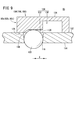
- FIG. 9 is a diagram showing the structure of the switching mechanism and its surroundings.
- 10A to 10E are diagrams showing a stud supply procedure.
- FIG. 11 is a diagram showing the appearance of the stud filling device.
- FIG. 11 is a diagram showing the appearance of the stud filling device.
- FIG. 12 is a view showing a side surface of the stud filling device.
- FIG. 13A is a diagram showing a state in which the studs are housed in the tube
- FIG. 13B is a diagram showing a state in which the studs are supplied from the tube to the magazine.
- FIG. 14A is a diagram showing a locked state of the switching mechanism
- FIG. 14B is a diagram showing an unlocked state of the switching mechanism.
- FIG. 15 is a diagram showing a state in which the stud filling device is aligned under the stud feeding device.
- FIG. 16 is a diagram showing a state in which the stud filling device is moved from below the stud feeding device.
- FIG. 13A is a diagram showing a state in which the studs are housed in the tube
- FIG. 13B is a diagram showing a state in which the studs are supplied from the tube to the magazine.
- FIG. 14A is a diagram showing a locked state of the switching mechanism
- FIG. 17 is a diagram showing a state in which the stud supply device approaches the stud filling device.
- FIG. 18 is a diagram showing a state in which the stud supply device is aligned with the stud filling device.
- FIG. 19 is a diagram showing a state in which studs are supplied from the stud filling device to the stud supply device.
- the projection welding system 10 includes a projection welding device 12, a stud filling device 14, and a stud feeding device 16.
- the projection welding device 12 includes an articulated robot 18, a stud gun 20 operated by the robot 18, and a stud supply device 22 that supplies studs 24 (FIG. 2) to the second electrode 38 of the stud gun 20. ..
- the stud 24 used in the present embodiment is a flanged stud having a shaft portion 26 and a flange 28 formed at the base end of the shaft portion 26.
- the stud 24 is housed in the stud feeding device 16, is sent from the stud feeding device 16 to the stud filling device 14, is sent from the stud filling device 14 to the stud feeding device 22, is ejected from the stud feeding device 22, and is second. It is supplied to the electrode 38.
- the longitudinal direction of the stud gun 20 is the X direction (left and right direction on the paper surface in FIG. 1)
- the height direction orthogonal to the X direction is the Y direction (vertical direction on the paper surface in FIG. 1)
- the direction is orthogonal to the X direction and the Y direction.
- the width direction is the Z direction (FIG. 1, the direction perpendicular to the paper surface).
- one of the X directions is the + X direction, and the other is the ⁇ X direction. The same applies to the Y direction and the Z direction.
- the stud gun 20 has a first arm 30 and a second arm 32 that can be approached to each other and separated from each other.
- a first electrode 34 as a welding electrode is attached to the tip of the first arm 30 with the tip facing the second electrode 38.
- An electrode switching device 36 is attached to the tip of the second arm 32.
- a stud supply device 22 is attached to the second arm 32 on the proximal end side of the electrode switching device 36.
- the electrode switching device 36 has two second electrodes 38 as welding electrodes.
- One second electrode 38a is arranged on the + Z direction side (front side of the paper surface) with respect to the other second electrode 38b.
- the two second electrodes 38 can swing in the XY plane about an axis extending in the Z direction, and can move in the Z direction at the same time.
- the electrode switching device 36 is controlled by a control device (not shown).
- one second electrode 38a When the two second electrodes 38 are arranged on the + Z direction side (front side of the paper surface), one second electrode 38a has its tip directed toward the stud supply device 22 on the + X direction side, and the other second electrode 38b The tip thereof is directed to the first electrode 34 on the + Y direction side.
- the first electrode 34 and the other second electrode 38b perform projection welding with the stud 24 and the work W sandwiched between them, and the stud supply device 22 supplies the stud 24 to the one second electrode 38a.
- one second electrode 38a When two second electrodes 38 are arranged on the ⁇ Z direction side (back side of the paper surface), one second electrode 38a has its tip directed toward the first electrode 34 on the + Y direction side, and the other second electrode 38b Directs its tip toward the stud supply device 22 on the + X direction side.
- the first electrode 34 and one of the second electrodes 38a perform projection welding with the stud 24 and the work W sandwiched between them, and the stud supply device 22 supplies the stud 24 to the other second electrode 38b.
- Second electrode 38 [3.1. Configuration of the second electrode 38]
- the configuration of the second electrode 38 will be described with reference to FIGS. 3 and 4.
- the end portion on the tip end side of the second electrode 38 is set as the tip end, and the portion located on the tip end side is set as the tip end portion.
- the end portion on the proximal end side of the second electrode 38 is the proximal end, and the portion located on the proximal end side is the proximal end portion.
- the second electrode 38 has a first holding portion 40 and a second holding portion 42.
- the first holding portion 40 is a rod-shaped member located on the proximal end side of the second electrode 38, and a conductive member (not shown) is inserted therein.
- the conductive member is connected to a circuit (not shown) that supplies a welding current.
- the base end portion of the first holding portion 40 is attached to a swing arm (not shown) of the electrode switching device 36.
- the tip of the first holding portion 40 holds the second holding portion 42.
- the second holding portion 42 includes an electrode body 46, a magnet portion 48 that attracts the stud 24 by magnetic force, and a cap 50 that functions as an electrode tip.
- the electrode body 46 is a conductive member such as metal, and has a magnet storage hole 52 and one or more horizontal holes 54.
- the electrode body 46 is attached to the tip of the first holding portion 40 and is connected to the conductive member of the first holding portion 40.
- the magnet accommodating hole 52 is formed along the axis of the electrode body 46 from the tip opening 56a formed on the tip surface 56 of the electrode body 46 to the bottom 58 formed on the base end side of the tip opening 56a.
- the lateral hole 54 is formed along the diameter of the electrode body 46 from the side wall opening 60a formed in the side wall 60 of the electrode body 46 to the bottom portion 58.
- the magnet portion 48 has a cylindrical magnet 62 and a non-magnetic body 64 that covers the entire surface of the magnet 62.
- the non-magnetic material 64 has a first stud holding hole 66 penetrating the center.
- the magnet portion 48 is fitted in the magnet storage hole 52 of the electrode body 46, and is held at a position where the lateral hole 54 is not blocked.
- the magnet portion 48 may be provided with a flow path through which the cooling medium flows.
- the cap 50 is a conductive member such as metal.
- the cap 50 has a cap opening 68 formed at the tip thereof and a second stud holding hole 70 connected to the cap opening 68 and penetrating the center of the cap 50.
- the cap 50 is screwed into the side wall 60 at the tip of the electrode body 46 and comes into contact with the tip of the electrode body 46 and the tip of the non-magnetic body 64 of the magnet portion 48 fitted in the magnet storage hole 52.
- the first stud holding hole 66 and the second stud holding hole 70 form the stud holding hole 72 by aligning their axes with each other.
- the stud holding hole 72 is connected to the lateral hole 54 at the position of the bottom portion 58. Therefore, the cap opening 68 (first opening) and the side wall opening 60a (second opening) communicate with each other through the stud holding hole 72 and the lateral hole 54.
- the diameter of the stud holding hole 72 is larger than the diameter of the shaft portion 26 of the stud 24. Further, the diameter of the cap opening 68 is smaller than the diameter of the flange 28 of the stud 24.
- the stud 24 is pulled by the magnetic force of the magnet 62 with the shaft portion 26 inserted into the stud holding hole 72 and the flange 28 in contact with the tip of the cap 50.
- an air injection portion for injecting air from the cap opening 68 (first opening) of the second electrode 38 into the stud holding hole 72 is provided.
- the tip of the second electrode 38 is directed toward the stud supply device 22 according to the operation of the electrode switching device 36.
- the stud supply device 22 is an air transport type stud supply unit that inserts the stud 24 into the stud holding hole 72 by utilizing the pressure of air.
- the stud supply device 22 is used as an air injection unit.
- the cleaning air 74 blows the dust 76 accumulated in the stud holding hole 72 and the lateral hole 54 to the outside from the side wall opening 60a.
- the stud holding hole 72 and the lateral hole 54 are cleaned by removing dust 76.
- the projection welding device 12 has two stud supply devices 22.
- One stud supply device 22 is arranged on the + Z direction side with respect to the second arm 32 (FIG. 7), and supplies the stud 24 to the second electrode 38a.
- the other stud supply device 22 is arranged on the ⁇ Z direction side with respect to the second arm 32 (FIG. 7), and supplies the stud 24 to the second electrode 38b.
- the stud supply device 22 includes a magazine 80, a plurality of switching mechanisms 82 (first switching mechanism 82a to third switching mechanism 82c), a first cylinder 84, a second cylinder 86, a third cylinder 88, and a first cylinder. It has an air injection unit 90 and a second air injection unit 92. Further, the base 94 is fixed to the inner surface of the second arm 32 (the surface on the first arm 30 side). The support member 96 is fixed to the base 94. The support member 96 projects over the second arm 32 in the + Z direction side and the ⁇ Z direction side to support the two stud supply devices 22.
- the magazine 80 supported by the support member 96 will be described.
- the magazine 80 is a cylinder that stores a predetermined number of studs 24.
- the axis of the magazine 80 is arranged parallel to the X direction (supply direction of the stud 24), and the magazine 80 is movably supported in the + X direction and the ⁇ X direction by the support member 96.
- the magazine 80 has a magazine hole 98 penetrating from one end on the + X direction side to the other end on the ⁇ X direction side, a guide port 100 located at one end of the magazine hole 98, and an injection port 102 located at the other end of the magazine hole 98. And have.
- a stop portion 104 for stopping the stud 24 immediately before injection is provided in a portion of the magazine hole 98 near the injection port 102.
- a first standby portion 106 and a second standby portion 108 for stopping the stud 24 before moving it to the stop portion 104 are provided. ..
- the diameter of the magazine hole 98 is longer than the diameter of the flange 28 of the stud 24 and shorter than the total length of the stud 24. Further, the length of the magazine hole 98 in the axial direction is longer than the total length of the studs 24 for a predetermined number of minutes. Therefore, the magazine 80 can store a predetermined number of studs 24 in series (one row) from the stop portion 104 toward the + X direction inside the magazine hole 98. Further, the magazine 80 can insert the stud 24 through the guide port 100 and eject it from the injection port 102.
- a magazine sensor 110 that detects the tip of the stud 24 that stops at the stop portion 104 is provided.
- the magazine sensor 110 is, for example, a photoelectric sensor.
- the magazine 80 has a plurality of magazine through holes 116 penetrating from the magazine outer wall 112 to the magazine inner wall 114 at the position of the stop portion 104.
- a plurality of magazine through holes 116 are provided in the stop portion 104.
- the plurality of magazine through holes 116 are arranged in the circumferential direction of the cross section of the stop portion 104 (the cross section orthogonal to the axis of the magazine 80).
- the magazine 80 has a magazine through hole 116 having the same shape as the stop portion 104 at the position of the first standby portion 106 and the position of the second standby portion 108. The distance between the first standby unit 106 and the second standby unit 108 is shorter than the length of the stud 24.
- the stop portion 104 is provided with a first switching mechanism 82a.
- the first switching mechanism 82a has a plurality of balls 122 (FIGS. 8 and 9) and a reciprocating member 124 (FIGS. 6 to 9). The first switching mechanism 82a switches between a state in which the stud 24 is stopped and a state in which the stud 24 is passed by the stop portion 104.
- the balls 122 are housed inside each magazine through hole 116, and can move inside and outside the magazine 80 in the radial direction inside the magazine through hole 116.
- the ball 122 is smaller than the outer wall opening 120 of the magazine through hole 116 and larger than the inner wall opening 118. When the outer end of the ball 122 is in the vicinity of the outer wall opening 120, a part of the ball 122 projects from the inner wall opening 118 into the magazine hole 98.
- the reciprocating member 124 is a cylindrical member.
- the reciprocating member 124 is provided around the magazine outer wall 112 and can slide in the + X direction and the ⁇ X direction along the magazine outer wall 112.
- the reciprocating member 124 has a recess 128 that circulates on the inner peripheral surface 126 that faces the outer wall 112 of the magazine.
- the recess 128 has a large diameter portion 130 having a large diameter on the + X direction side and a small diameter portion 132 having a small diameter on the ⁇ X direction side.
- the second switching mechanism 82b switches between a state in which the stud 24 is stopped and a state in which the stud 24 is passed by the first standby unit 106.
- the third switching mechanism 82c switches between a state in which the stud 24 is stopped and a state in which the stud 24 is passed by the second standby unit 108.
- the structure and operation of the second switching mechanism 82b and the third switching mechanism 82c are the same as the structure and operation of the first switching mechanism 82a.
- the switching mechanism 82 operates as follows.
- the ball 122 is between the large diameter portion 130 and the magazine through hole 116 when the reciprocating member 124 moves in the ⁇ X direction and the large diameter portion 130 of the reciprocating member 124 faces the outer wall opening 120 of the magazine through hole 116. It becomes possible to move with.
- the plurality of balls 122 can make the size of the magazine hole 98 (FIG. 8) larger than the diameter of the flange 28 of the stud 24.
- the stud 24 pushes the plurality of balls 122 outward to widen the diameter of the stop portion 104, so that the stud 24 can pass through the stop portion 104.
- the ball 122 comes into contact with the peripheral surface of the small diameter portion 132 when the reciprocating member 124 moves in the + X direction and the small diameter portion 132 of the reciprocating member 124 faces the outer wall opening 120 of the magazine through hole 116.
- the movement of the ball 122 is restricted by the reciprocating member 124 in a state where a part of the ball 122 protrudes from the inner wall opening 118 of the magazine through hole 116 into the magazine hole 98.
- the stud 24 cannot push the plurality of balls 122 to the outside, so that the stud 24 cannot pass through the stop portion 104.
- the first cylinder 84 is a fluid pressure cylinder that operates the first rod 134 in the + X direction and the ⁇ X direction.
- the first cylinder 84 is arranged on the + X direction side of the first switching mechanism 82a to the third switching mechanism 82c and is connected to the magazine 80.
- the first rod 134 extends from the first cylinder 84 in the ⁇ X direction and is connected to the reciprocating member 124 of the first switching mechanism 82a and the reciprocating member 124 of the third switching mechanism 82c.
- the first cylinder 84 operates the first switching mechanism 82a and the third switching mechanism 82c at the same time.
- the second cylinder 86 is a fluid pressure cylinder that operates the second rod 136 in the + X direction and the ⁇ X direction.
- the second cylinder 86 is arranged on the + X direction side of the first switching mechanism 82a to the third switching mechanism 82c and is fixed to the magazine 80.
- the second rod 136 extends from the second cylinder 86 in the ⁇ X direction and is connected to the reciprocating member 124 of the second switching mechanism 82b.
- the second cylinder 86 operates the second switching mechanism 82b separately from the first switching mechanism 82a and the third switching mechanism 82c.
- the third cylinder 88 is a fluid pressure cylinder that operates the third rod 138 in the + X direction and the ⁇ X direction.
- the third cylinder 88 is fixed to the surface of the support member 96 on the ⁇ X direction side.
- the third rod 138 penetrates the support member 96 and extends in the + X direction, and is connected to the surface of the connecting plate 140 fixed to the base end portion of the magazine 80 on the ⁇ X direction side.
- the first guide shaft 142 is connected to the surface of the connecting plate 140 on the + X direction side.
- the first guide shaft 142 extends from the connecting plate 140 in the + X direction and is connected to the pedestal 158 of the second air injection unit 92, which will be described later.
- the first guide shaft 142 is movably supported in the + X direction and the ⁇ X direction by the guide member 144 fixed to the end of the support member 96 on the + X direction side.
- the third cylinder 88 is a member connected to the connecting plate 140, specifically, a magazine 80 and each configuration connected to the magazine 80 (each switching mechanism 82, the first cylinder 84, the second cylinder 86, the first air injection). (Part 90, etc.) and each configuration (second air injection part 92) connected to the pedestal 158 are operated in the + X direction and the ⁇ X direction with reference to the support member 96.
- the first air injection unit 90 is provided between the stop unit 104 of the magazine 80 and the first standby unit 106.
- the first air injection unit 90 has an air supply path 146 that goes around the magazine outer wall 112.
- the first air injection unit 90 is connected to an air supply circuit (not shown) having an air pump.
- an air supply hole 148 is formed from the magazine outer wall 112 to the magazine inner wall 114.
- a plurality of air supply holes 148 are provided.
- the air supply hole 148 communicates with the air supply path 146.
- the air supply hole 148 has a structure in which the flow path on the downstream side is located on the ⁇ X direction side with respect to the flow path on the upstream side. Therefore, the first air injection unit 90 injects the air flowing into the air supply hole 148 from the air supply path 146 toward the ⁇ X direction inside the magazine hole 98.
- the second air injection unit 92 is provided on the + X direction side of the base end of the magazine 80.
- the second air injection unit 92 is connected to an air supply circuit (not shown) having an air pump.
- the second air injection unit 92 brings the nozzle 150 close to the guide port 100 of the magazine 80. Therefore, the second air injection unit 92 injects air from the nozzle 150 toward the inside of the magazine hole 98.
- the second air injection unit 92 has an injection unit bracket 152 extending in the + Z direction.
- the second guide shaft 154 is parallel to the Y direction and is inserted into the holes formed in the coil spring 156 and the pedestal 158.
- the end of the second guide shaft 154 on the + Y direction side is fixed to the injection portion bracket 152, and the end of the second guide shaft 154 on the ⁇ Y direction side is fixed to the stop member 160 on the ⁇ Y direction side of the pedestal 158.
- the stop member 160 is larger than the hole of the pedestal 158 through which the second guide shaft 154 is inserted, the second guide shaft 154 does not come out of the hole.
- the coil spring 156 comes into contact with the end face of the injection portion bracket 152 on the ⁇ Y direction side and the end face of the pedestal 158 on the + Y direction side.
- the second air injection unit 92 stops with the nozzle 150 close to the base end of the magazine 80, and supplies air to the magazine hole 98 of the magazine 80. Further, the second air injection unit 92 can compress the coil spring 156 and move in the ⁇ Y direction by being pushed in the ⁇ Y direction. In this state, the guide port 100 of the magazine 80 is not blocked by the second air injection unit 92, so that the stud 24 can be filled into the magazine hole 98 of the magazine 80.
- the work of filling the stud 24 into the magazine hole 98 is performed by the stud filling device 14 (FIG. 1 and the like).
- the stud supply device 22 is provided with a first male portion 162 and a first female portion 164.
- the first male portion 162 is fixed to the base 94 and projects in the + Y direction from between the magazine 80 of one stud supply device 22 and the magazine 80 of the other stud supply device 22.
- the first female portion 164 is fixed to the surface of the support member 96 on the + Y direction side.
- the filling work of the stud 24 will be described in [5.2].
- each switching mechanism 82 (82a to 82c) operates the reciprocating member 124 to switch between a state in which the movement of the ball 122 is restricted and a state in which the restriction on the movement of the ball 122 is released.
- the state in which the switching mechanism 82 restricts the movement of the ball 122 is referred to as a locked state
- the state in which the switching mechanism 82 releases the restriction on the movement of the ball 122 is referred to as an unlocked state.
- the three studs 24 are also referred to as a first stud 24a, a second stud 24b, and a third stud 24c in order from the beginning.
- FIG. 10A shows the first step in which the stud 24 is filled in the magazine hole 98.
- the reciprocating member 124 of the second switching mechanism 82b is arranged on the + X direction side to lock the second switching mechanism 82b.
- the reciprocating member 124 of the third switching mechanism 82c is arranged on the ⁇ X direction side to bring the third switching mechanism 82c into the unlocked state.
- the first stud 24a passes through the second standby unit 108. Further, the ball 122 of the second switching mechanism 82b comes into contact with the flange 28 of the first stud 24a. Therefore, the first stud 24a stops at the first standby unit 106. At this time, the second stud 24b comes into contact with the first stud 24a and stops on the + X direction side of the second standby portion 108. As a result, the state shown in FIG. 10A is obtained.
- FIG. 10B shows a second step performed after the first step.
- the reciprocating member 124 of the first switching mechanism 82a and the third switching mechanism 82c is arranged on the + X direction side, and the first switching mechanism 82a and the third switching mechanism 82c are locked. To do.
- the state shown in FIG. 10B is obtained.
- the stop position of each stud 24 does not change.
- air is injected into the magazine hole 98 from the second air injection unit 92 (FIG. 6 and the like).
- the posture of each stud 24 is corrected by air, and the tip thereof is directed in the air flow direction, that is, in the ⁇ X direction.
- FIG. 10C shows a third step performed after the second step.
- the reciprocating member 124 of the second switching mechanism 82b is arranged on the ⁇ X direction side to bring the second switching mechanism 82b into the unlocked state.
- the ball 122 of the second switching mechanism 82b is pushed by the first stud 24a provided with propulsive force by air and moves outward. Therefore, the first stud 24a passes through the first standby unit 106 and proceeds to the stop unit 104.
- the ball 122 of the first switching mechanism 82a comes into contact with the flange 28 of the first stud 24a. Therefore, the first stud 24a stops at the stop portion 104.
- the second stud 24b to which the propulsion force is given by the air advances to the second standby portion 108.
- the ball 122 of the third switching mechanism 82c comes into contact with the flange 28 of the second stud 24b. Therefore, the second stud 24b stops at the second standby unit 108.
- air is injected from the first air injection unit 90 into the magazine hole 98.
- the posture of the first stud 24a is corrected by the air, and the tip thereof is directed in the air flow direction, that is, in the ⁇ X direction. As a result, the state shown in FIG. 10C is obtained.
- FIG. 10D shows a fourth step performed after the third step.
- the second cylinder 86 arranges the reciprocating member 124 of the second switching mechanism 82b on the + X direction side to lock the second switching mechanism 82b.
- the state shown in FIG. 10D is obtained.
- the stop position of each stud 24 does not change.
- FIG. 10E shows a fifth step performed after the fourth step.
- the reciprocating member 124 of the first switching mechanism 82a and the third switching mechanism 82c is arranged on the ⁇ X direction side to bring the first switching mechanism 82a and the third switching mechanism 82c into the unlocked state.
- the ball 122 of the first switching mechanism 82a is pushed by the first stud 24a provided with propulsive force by air and moves outward. Therefore, the first stud 24a passes through the stop portion 104 and is ejected from the injection port 102. Further, the ball 122 of the second switching mechanism 82b comes into contact with the flange 28 of the second stud 24b. Therefore, the second stud 24b stops at the first standby unit 106.
- Stud filling device 14 [5.1. Configuration of stud filling device 14] The configuration of the stud filling device 14 will be described with reference to FIGS. 1 and 11 to 16. As shown in FIG. 1, the stud filling device 14 is supported by a support base 170, rotates about an axis extending in the vertical direction, and receives a stud 24 from the stud feeding device 16 (FIG. 15). , It is possible to move between the position where the stud supply device 22 is filled with the stud 24 (FIG. 16).
- the stud filling device 14 is composed of a plurality of parts attached to the vertical plate 172 supported by the support base 170 and a plurality of parts attached to those parts.
- a second female portion 174, a second male portion 176, two first brackets 178, two horizontal plates 180, and two second brackets 182 are attached to the vertical plate 172 in this order from the bottom.
- the second female part 174 and the second male part 176 project forward from the vertical plate 172.
- the two first brackets 178 extend forward from the vertical plate 172 and individually support the sensor support member 184.
- the sensor support member 184 supports the lower tube sensor 186.
- the lower tube sensor 186 is located below the lower end of the tube 190.
- the two horizontal plates 180 extend forward from the vertical plate 172 and individually support the tube 190 and the roller support 192.
- a pin 189 extending downward is rotatably attached to the horizontal plate 180 about its axis.
- a fourth cylinder 188 is fixed to the lower end of the pin 189.
- the pin 189 rotatably supports the fourth cylinder 188.
- the roller support portion 192 rotatably supports the roller 194.
- the roller 194 projects forward of the tube 190.
- the two second brackets 182 extend forward from the vertical plate 172 and individually support the upper tube sensor 196.
- the tube 190 extends in the vertical direction and is supported by the horizontal plate 180.
- the upper end of the tube 190 is located above the horizontal plate 180 and the lower end of the tube 190 is located below the horizontal plate 180.
- a switching mechanism 198 is provided at the lower end of the tube 190 arranged below the horizontal plate 180.
- One tube 190 fills one of the two stud feeders 22 with the stud 24, and the other tube 190 fills the other of the two stud feeders 22 with the stud 24.
- a flange 199 extending in the horizontal direction is formed on the outer peripheral surface of the switching mechanism 198.
- the shaft member of the joint 201 is inserted through a part of the flange 199.
- the shaft member of the joint 201 extends in the vertical direction.
- the rear end of the joint 201 is connected to the tip of the fourth rod 200 extending forward from the fourth cylinder 188.
- the tube 190 is a cylinder for accommodating a predetermined number of studs 24.
- the tube 190 has a tube hole 210 that penetrates from one upper end to the other end of the lower side, a guide port 212 located at one end of the tube hole 210, and a discharge port 214 located at the other end of the tube hole 210. ..
- a stop portion 216 for stopping the leading stud 24 is provided in a portion of the tube hole 210 close to the discharge port 214.
- the diameter of the tube hole 210 is longer than the diameter of the flange 28 of the stud 24 and shorter than the total length of the stud 24. Further, the axial length of the tube hole 210 is longer than the total length of the studs 24 for a predetermined number of minutes. Therefore, the tube 190 can store a predetermined number of studs 24 in series (one row) downward from the stop portion 216 inside the tube hole 210. Further, the tube 190 can insert the stud 24 through the guide port 212 and eject it from the discharge port 214.
- a lower tube sensor 186 that detects the tip of the stud 24 that stops at the stop portion 216 is provided below the lower end of the tube 190.
- an upper tube sensor 196 for detecting the stud 24 located at the end of a predetermined number of studs 24 housed in the tube hole 210 is provided at the upper end of the tube 190.
- the lower tube sensor 186 and the upper tube sensor 196 are, for example, photoelectric sensors.
- the tube 190 has a plurality of tube through holes 222 penetrating from the tube outer wall 218 to the tube inner wall 220 at the position of the stop portion 216.
- the plurality of tube through holes 222 are arranged in the circumferential direction of the cross section of the stop portion 216 (the cross section orthogonal to the axis of the tube 190).
- the switching mechanism 198 has a plurality of balls 224 and a rotating member 226.
- the switching mechanism 198 switches between a state in which the stud 24 is stopped and a state in which the stud 24 is passed by the stop portion 216.
- the ball 224 is housed inside each tube through hole 222 and can be moved inside and outside the tube 190 in the radial direction inside the tube through hole 222.
- the ball 224 is smaller than the outer wall opening 228 of the tube through hole 222 and larger than the inner wall opening 230.
- a portion of the ball 224 projects from the inner wall opening 230 into the tube hole 210.
- the rotating member 226 is a cylindrical member.
- the rotating member 226 is provided around the tube outer wall 218 and is slidable along the tube outer wall 218 in the circumferential direction of the tube 190.
- the rotating member 226 has a recess 234 on the inner peripheral surface 232 facing the outer wall 218 of the tube.
- the recesses 234 are arranged in the circumferential direction of the cross section of the stop portion 216 (the cross section orthogonal to the axis of the tube 190).
- the switching mechanism 198 operates as follows.
- the ball 224 can move between the recess 234 and the tube through hole 222 when the rotating member 226 rotates and the recess 234 of the rotating member 226 faces the outer wall opening 228 of the tube through hole 222. ..
- the plurality of balls 224 can make the size of the stop portion 216 larger than the diameter of the flange 28 of the stud 24.
- the stud 24 pushes the plurality of balls 224 outward by its own weight to expand the stop portion 216, so that the stud 24 can pass through the stop portion 216.
- the ball 224 comes into contact with the inner peripheral surface 232 when the rotating member 226 rotates and the recess 234 of the rotating member 226 does not face the outer wall opening 228 of the tube through hole 222.
- the movement of the ball 224 is restricted by the rotating member 226 with a part of the ball 224 protruding from the inner wall opening 230 of the tube through hole 222 into the tube hole 210. Then, since the stud 24 cannot push the plurality of balls 224 outward, it cannot pass through the stop portion 216.
- the switching mechanism 198 operates the rotating member 226 to switch between a state in which the movement of the ball 224 is restricted and a state in which the movement of the ball 224 is released.
- the state in which the switching mechanism 198 restricts the movement of the ball 224 is referred to as a locked state
- the state in which the switching mechanism 198 releases the restriction on the movement of the ball 122 is referred to as an unlocked state.
- a control device (not shown) controls the operation of each device in an integrated manner.
- the support base 170 arranges the stud filling device 14 under the stud feeding portion 171 of the stud feeding device 16.
- the arm 240 provided on the support 170 can rotate between two positions. When the arm 240 turns in one direction, the stud filling device 14 is arranged under the stud feeding portion 171 of the stud feeding device 16 and can receive the stud 24 from the stud feeding device 16.
- the parts storage process is performed.
- the fourth cylinder 188 rotates the rotating member 226 of the switching mechanism 198 to lock the switching mechanism 198.
- the ball 224 moves toward the inside of the stop portion 216 to make the size of the stop portion 216 smaller than the flange 28 of the stud 24.
- the stud feeding device 16 drops a predetermined number of studs 24 toward the tube holes 210.
- the stud 24 is inserted into the tube hole 210 with its tip facing down.
- the upper tube sensor 196 detects the filling completion state. Then, the stud feed device 16 stops the supply of the stud 24.
- the support 170 moves the stud filling device 14 from below the stud feeding device 16 as shown in FIG.
- the arm 240 turns to the other side, the stud filling device 14 moves from under the stud feeding device 16.
- the robot 18 brings the stud supply device 22 closer to the stud filling device 14 with the tip side ( ⁇ X direction side) of the stud gun 20 facing downward. At this time, the robot 18 adjusts the positions of the stud supply device 22 in the X direction and the Z direction, and moves the stud supply device 22 in front of the stud filling device 14. Then, the robot 18 arranges the injection portion bracket 152 in front of the roller 194, the first female portion 164 in front of the second male portion 176, and the first male portion 162 in front of the second female portion 174. Deploy.
- the robot 18 gradually moves the stud gun 20 in the rear direction (+ Y direction) to bring the stud supply device 22 closer to the stud filling device 14. Then, the injection portion bracket 152 and the roller 194 come into contact with each other. Further, the robot 18 moves the stud gun 20 in the rear direction (+ Y direction). Then, as shown in FIG. 18, the second air injection unit 92 moves in the forward direction ( ⁇ Y direction) together with the injection unit bracket 152 and the second guide shaft 154. At this time, the coil spring 156 is compressed. When the first female portion 164 and the second male portion 176 come into contact with each other and the first male portion 162 and the second female portion 174 come into contact with each other, the robot 18 stops the movement of the stud gun 20. At this time, the axis of the tube 190 and the axis of the magazine 80 coincide with each other.
- the third cylinder 88 moves the magazine 80 upward (+ X direction) as shown in FIG.
- the injection portion bracket 152 moves smoothly in the upward direction (+ X direction) due to the rotation of the roller 194.
- the first male portion 162 fixed to the base 94 and the first female portion 164 fixed to the support member 96 do not move.
- the guide port 100 of the magazine 80 approaches the discharge port 214 of the tube 190, as shown in FIG. 13A.
- the position of the light passage hole 242 formed around the guide port 100 of the magazine 80 and the position of the lower tube sensor 186 are aligned, and the lower tube sensor 186 stores a predetermined number of studs 24 in the magazine 80. You will be able to detect that.
- the fourth cylinder 188 rotates the rotating member 226 of the switching mechanism 198 to bring the switching mechanism 198 into the unlocked state.
- the ball 224 is pushed toward the outside of the stop portion 216 by the weight of the stud 24. Therefore, the ball 224 moves toward the outside of the stop portion 216 to make the size of the stop portion 216 larger than the flange 28 of the stud 24.
- the stud 24 falls with its tip facing downward and is inserted into the magazine hole 98.
- the configuration of the stud supply device 22 and the stud filling device 14 described above can be used for other component supply devices and component filling devices.
- the configuration of the stud supply device 22 can be used for a bolt supply device that supplies bolts to the tip of the arm of the robot 18.
- the configuration of the stud filling device 14 can be used for a bolt filling device or the like for filling the bolt supply device with bolts.
- the first aspect of the present invention is A parts filling device that temporarily stores a predetermined number of parts (studs 24) supplied from a parts feeding device (stud feeding device 16) and fills a predetermined number of the stored parts into a predetermined machine (stud feeding device 22).
- a parts feeding device stud feeding device 16
- stud feeding device 22 stud feeding device 22
- Stud filling device 14 It has a component storage hole (tube hole 210) that penetrates in the vertical direction, and the component can be inserted from the upper end (guide port 212) of the component storage hole and ejected from the lower end (discharge port 214).
- the parts can be stopped by the stop portion 216 located on the lower end side of the storage hole, and a predetermined number of the parts are connected in series from the stop portion 216 toward the upper end side inside the component storage hole.
- a parts storage unit (tube 190) that can be stored side by side, It has a plurality of moving bodies (balls 224) capable of moving between a position where the parts are in contact with the parts and a position where the moving bodies are not in contact with the parts, and a lock portion (rotating member 226) for restricting the movement of the plurality of moving bodies. Then, the switching mechanism 198 for switching between the state in which the component is stopped and the state in which the component is passed by the stop unit 216, and To be equipped.
- the parts filling device (stud filling device 14) is interposed between the parts feeding device (stud feeding device 16) and the parts feeding device (stud feeding device 22). Therefore, a transport unit (hose) is not provided between the parts feeding device (stud feeding device 16) and the parts feeding device (stud feeding device 22). As a result, even if the stud gun 20 moves during the welding work, the problem that the transport portion comes into contact with the work W or the like does not occur.
- a predetermined number of parts are arranged and stored in series inside the parts storage hole (tube hole 210) through which the parts storage portion (tube 190) penetrates in the vertical direction.
- a predetermined number of parts can be filled in the parts supply device only by moving the parts supply device (stud supply device 22) under the parts storage unit and dropping the parts.
- the parts feeding device stud feeding device 16
- the parts feeding device fills the parts feeding device with a predetermined number of parts so as not to come into contact with the work W or the like during the welding work of the stud gun 20. Can be done.
- the plurality of moving bodies are arranged in the circumferential direction of the cross section of the stop portion 216, move toward the inside of the stop portion 216, and adjust the size of the stop portion 216 to the size of the component (stud 24).
- the part can be stopped by making it smaller than the size, and the part can be stopped by moving toward the outside of the stop portion 216 and making the size of the stop portion 216 larger than the size of the part.
- the lock portion may restrict the movement of the plurality of the moving bodies in a state where the plurality of the moving bodies have the size of the stop portion smaller than the size of the parts.
- the component storage portion (tube 190) at the position of the stop portion 216 is a cylinder having an outer wall (tube outer wall 218) and an inner wall (tube inner wall 220).
- the cylinder has a plurality of cylinder through holes (tube through holes 222) that penetrate from the outer wall to the inner wall and are arranged along the outer circumference of the cross section of the stop portion 216.
- the moving body is a ball 224 that can move inside the cylinder through hole.
- the lock portion has a rotating member 226 that surrounds the outer wall of the cylinder, covers the opening on the outer wall side of the cylinder through hole, and is rotatable about the axis of the stop portion 216.
- the rotating member 226 has a plurality of recesses 234 arranged on the inner peripheral surface 232 facing the outer wall of the cylinder at the same intervals as the intervals between the plurality of cylinder through holes.
- the opening on the inner wall side of the cylinder through hole (inner wall opening 230) has a size or shape that allows a part of the ball 224 to protrude inside the stop portion 216.
- the ball 224 can move between the recess 234 and the cylinder through hole when the rotation position of the rotating member 226 is a position where the recess 234 faces the cylinder through hole.
- the movement may be restricted by the rotating member 226.
- a drive source for operating the lock portion (rotating member 226) may be provided.
- the part is a stud 24 that is welded to the work W by projection welding.
- the predetermined machine may be a stud supply device 22 provided in the projection welding device 12 and supplying the stud 24 to the welding electrode (second electrode 38).
- the second aspect of the present invention is A predetermined number of the parts (studs 24) supplied from the parts feeding device (stud feeding device 16) are temporarily stored and stored by using the parts filling device (stud filling device 14) of the first aspect.
- a component storage process in which a predetermined number of the parts are supplied from the component feeding device to the component storage hole (tube hole 210) and the predetermined number of the parts are stored in the component storage hole in a regulated state.
- the parts filling step of dropping the parts and filling the predetermined machine, including.
- component filling device and the component filling method according to the present invention are not limited to the above-described embodiments, and it goes without saying that various configurations can be adopted without departing from the gist of the present invention.
Landscapes
- Engineering & Computer Science (AREA)
- Mechanical Engineering (AREA)
- Physics & Mathematics (AREA)
- Plasma & Fusion (AREA)
- Automatic Assembly (AREA)
- Portable Nailing Machines And Staplers (AREA)
Priority Applications (3)
| Application Number | Priority Date | Filing Date | Title |
|---|---|---|---|
| JP2021555929A JPWO2021095365A1 (https=) | 2019-11-13 | 2020-09-23 | |
| CN202080079290.7A CN114728750A (zh) | 2019-11-13 | 2020-09-23 | 零部件填充装置和零部件填充方法 |
| US17/776,244 US20220388086A1 (en) | 2019-11-13 | 2020-09-23 | Component filling device and component filling method |
Applications Claiming Priority (2)
| Application Number | Priority Date | Filing Date | Title |
|---|---|---|---|
| JP2019205124 | 2019-11-13 | ||
| JP2019-205124 | 2019-11-13 |
Publications (1)
| Publication Number | Publication Date |
|---|---|
| WO2021095365A1 true WO2021095365A1 (ja) | 2021-05-20 |
Family
ID=75912030
Family Applications (1)
| Application Number | Title | Priority Date | Filing Date |
|---|---|---|---|
| PCT/JP2020/035717 Ceased WO2021095365A1 (ja) | 2019-11-13 | 2020-09-23 | 部品充填装置及び部品充填方法 |
Country Status (4)
| Country | Link |
|---|---|
| US (1) | US20220388086A1 (https=) |
| JP (1) | JPWO2021095365A1 (https=) |
| CN (1) | CN114728750A (https=) |
| WO (1) | WO2021095365A1 (https=) |
Families Citing this family (1)
| Publication number | Priority date | Publication date | Assignee | Title |
|---|---|---|---|---|
| CN116748637A (zh) * | 2023-07-26 | 2023-09-15 | 塔冠实业(上海)有限公司 | 一种螺柱焊送料器 |
Citations (10)
| Publication number | Priority date | Publication date | Assignee | Title |
|---|---|---|---|---|
| JPS60172668U (ja) * | 1984-04-20 | 1985-11-15 | 日産自動車株式会社 | ナツト供給装置 |
| JPS6128733U (ja) * | 1984-07-24 | 1986-02-20 | トヨタ自動車株式会社 | 薄板部品の供給装置 |
| US4600118A (en) * | 1984-02-02 | 1986-07-15 | Martin Gerald D | Ferrule dispenser |
| JPH02135131U (https=) * | 1989-04-14 | 1990-11-09 | ||
| JPH09155560A (ja) * | 1995-12-09 | 1997-06-17 | Yoshitaka Aoyama | 部品供給速度の制御装置 |
| JP2000015454A (ja) * | 1998-06-29 | 2000-01-18 | Yoshitaka Aoyama | 電気抵抗溶接における通電制御方法 |
| JP2000022388A (ja) * | 1998-03-05 | 2000-01-21 | Taiyo Yuden Co Ltd | 電子部品配置装置 |
| JP2004314134A (ja) * | 2003-04-17 | 2004-11-11 | Dengensha Mfg Co Ltd | 溶接ボルト供給方法と装置 |
| JP2012218069A (ja) * | 2011-04-05 | 2012-11-12 | Yoshitaka Aoyama | プロジェクションボルト供給装置 |
| JP2015509851A (ja) * | 2012-10-24 | 2015-04-02 | ブロイアー システムテクニク ゲーエムベーハー | 電極キャップ用マガジンを装填するための装置 |
Family Cites Families (1)
| Publication number | Priority date | Publication date | Assignee | Title |
|---|---|---|---|---|
| US3474890A (en) * | 1967-07-24 | 1969-10-28 | Studebaker Corp | Stud feeder mechanism |
-
2020
- 2020-09-23 US US17/776,244 patent/US20220388086A1/en active Pending
- 2020-09-23 WO PCT/JP2020/035717 patent/WO2021095365A1/ja not_active Ceased
- 2020-09-23 JP JP2021555929A patent/JPWO2021095365A1/ja active Pending
- 2020-09-23 CN CN202080079290.7A patent/CN114728750A/zh not_active Withdrawn
Patent Citations (10)
| Publication number | Priority date | Publication date | Assignee | Title |
|---|---|---|---|---|
| US4600118A (en) * | 1984-02-02 | 1986-07-15 | Martin Gerald D | Ferrule dispenser |
| JPS60172668U (ja) * | 1984-04-20 | 1985-11-15 | 日産自動車株式会社 | ナツト供給装置 |
| JPS6128733U (ja) * | 1984-07-24 | 1986-02-20 | トヨタ自動車株式会社 | 薄板部品の供給装置 |
| JPH02135131U (https=) * | 1989-04-14 | 1990-11-09 | ||
| JPH09155560A (ja) * | 1995-12-09 | 1997-06-17 | Yoshitaka Aoyama | 部品供給速度の制御装置 |
| JP2000022388A (ja) * | 1998-03-05 | 2000-01-21 | Taiyo Yuden Co Ltd | 電子部品配置装置 |
| JP2000015454A (ja) * | 1998-06-29 | 2000-01-18 | Yoshitaka Aoyama | 電気抵抗溶接における通電制御方法 |
| JP2004314134A (ja) * | 2003-04-17 | 2004-11-11 | Dengensha Mfg Co Ltd | 溶接ボルト供給方法と装置 |
| JP2012218069A (ja) * | 2011-04-05 | 2012-11-12 | Yoshitaka Aoyama | プロジェクションボルト供給装置 |
| JP2015509851A (ja) * | 2012-10-24 | 2015-04-02 | ブロイアー システムテクニク ゲーエムベーハー | 電極キャップ用マガジンを装填するための装置 |
Also Published As
| Publication number | Publication date |
|---|---|
| CN114728750A (zh) | 2022-07-08 |
| JPWO2021095365A1 (https=) | 2021-05-20 |
| US20220388086A1 (en) | 2022-12-08 |
Similar Documents
| Publication | Publication Date | Title |
|---|---|---|
| JP6352007B2 (ja) | 超高速ボルト送出システム | |
| JP2826544B2 (ja) | ベアリングの組立装置、その組立治具およびその組立ロボット | |
| JP7193546B2 (ja) | 抵抗スポットリベット溶接システムおよびその使用方法 | |
| JP2013069799A (ja) | 電子回路部品装着機 | |
| JP2010523438A (ja) | 装着装置並びに締結要素を供給する方法及び装置 | |
| US10752453B2 (en) | Joining apparatus, loading station, supply arrangement and method for loading a magazine | |
| WO2021095365A1 (ja) | 部品充填装置及び部品充填方法 | |
| WO2003002288A1 (en) | Method and device for welding projection bolt | |
| WO2007049374A1 (ja) | 軸状部品の供給装置 | |
| WO2021095364A1 (ja) | スタッド供給装置及びスタッド供給方法 | |
| WO2021095363A1 (ja) | プロジェクション溶接装置及びその電極清掃方法 | |
| JP2004082193A (ja) | 溶接ボルト供給方法と装置 | |
| JP4277929B2 (ja) | プロジェクションボルト溶接方法および溶接装置 | |
| JP2009062192A (ja) | 中空部品の供給ヘッド | |
| KR102645002B1 (ko) | 마그넷 삽입 자동화 라인 시스템 | |
| JP6444850B2 (ja) | スタッド溶接機におけるスタッドの保留、排出装置 | |
| JP6482623B2 (ja) | 電子回路部品装着機 | |
| JP2007167947A (ja) | 軸状部品の供給装置 | |
| CA3117991C (en) | Rivet dispenser reloading systems and methods of use thereof | |
| JP5686257B2 (ja) | 部品供給装置の保持ヘッド構造 | |
| TWI609740B (zh) | 連續式供料設備 | |
| JPH1058154A (ja) | プロジェクションナットの溶接装置 | |
| JP3760303B2 (ja) | プロジェクションボルトの溶接装置 | |
| JP4501138B2 (ja) | プロジェクション溶接装置 | |
| KR20030041108A (ko) | 프로젝션볼트의 용접방법 및 장치 |
Legal Events
| Date | Code | Title | Description |
|---|---|---|---|
| 121 | Ep: the epo has been informed by wipo that ep was designated in this application |
Ref document number: 20888569 Country of ref document: EP Kind code of ref document: A1 |
|
| ENP | Entry into the national phase |
Ref document number: 2021555929 Country of ref document: JP Kind code of ref document: A |
|
| NENP | Non-entry into the national phase |
Ref country code: DE |
|
| 122 | Ep: pct application non-entry in european phase |
Ref document number: 20888569 Country of ref document: EP Kind code of ref document: A1 |