WO2021095365A1 - Component filling device and component filling method - Google Patents
Component filling device and component filling method Download PDFInfo
- Publication number
- WO2021095365A1 WO2021095365A1 PCT/JP2020/035717 JP2020035717W WO2021095365A1 WO 2021095365 A1 WO2021095365 A1 WO 2021095365A1 JP 2020035717 W JP2020035717 W JP 2020035717W WO 2021095365 A1 WO2021095365 A1 WO 2021095365A1
- Authority
- WO
- WIPO (PCT)
- Prior art keywords
- component
- stud
- hole
- cylinder
- parts
- Prior art date
Links
Images


Classifications
-
- B—PERFORMING OPERATIONS; TRANSPORTING
- B23—MACHINE TOOLS; METAL-WORKING NOT OTHERWISE PROVIDED FOR
- B23K—SOLDERING OR UNSOLDERING; WELDING; CLADDING OR PLATING BY SOLDERING OR WELDING; CUTTING BY APPLYING HEAT LOCALLY, e.g. FLAME CUTTING; WORKING BY LASER BEAM
- B23K9/00—Arc welding or cutting
- B23K9/20—Stud welding
- B23K9/206—Stud welding with automatic stud supply
-
- B—PERFORMING OPERATIONS; TRANSPORTING
- B23—MACHINE TOOLS; METAL-WORKING NOT OTHERWISE PROVIDED FOR
- B23K—SOLDERING OR UNSOLDERING; WELDING; CLADDING OR PLATING BY SOLDERING OR WELDING; CUTTING BY APPLYING HEAT LOCALLY, e.g. FLAME CUTTING; WORKING BY LASER BEAM
- B23K11/00—Resistance welding; Severing by resistance heating
- B23K11/002—Resistance welding; Severing by resistance heating specially adapted for particular articles or work
- B23K11/004—Welding of a small piece to a great or broad piece
- B23K11/0046—Welding of a small piece to a great or broad piece the extremity of a small piece being welded to a base, e.g. cooling studs or fins to tubes or plates
- B23K11/0053—Stud welding, i.e. resistive
-
- B—PERFORMING OPERATIONS; TRANSPORTING
- B23—MACHINE TOOLS; METAL-WORKING NOT OTHERWISE PROVIDED FOR
- B23K—SOLDERING OR UNSOLDERING; WELDING; CLADDING OR PLATING BY SOLDERING OR WELDING; CUTTING BY APPLYING HEAT LOCALLY, e.g. FLAME CUTTING; WORKING BY LASER BEAM
- B23K11/00—Resistance welding; Severing by resistance heating
- B23K11/36—Auxiliary equipment
-
- B—PERFORMING OPERATIONS; TRANSPORTING
- B23—MACHINE TOOLS; METAL-WORKING NOT OTHERWISE PROVIDED FOR
- B23P—METAL-WORKING NOT OTHERWISE PROVIDED FOR; COMBINED OPERATIONS; UNIVERSAL MACHINE TOOLS
- B23P19/00—Machines for simply fitting together or separating metal parts or objects, or metal and non-metal parts, whether or not involving some deformation; Tools or devices therefor so far as not provided for in other classes
- B23P19/001—Article feeders for assembling machines
- B23P19/004—Feeding the articles from hoppers to machines or dispensers
- B23P19/005—Feeding the articles from hoppers to machines or dispensers by using flowing gases
-
- B—PERFORMING OPERATIONS; TRANSPORTING
- B65—CONVEYING; PACKING; STORING; HANDLING THIN OR FILAMENTARY MATERIAL
- B65G—TRANSPORT OR STORAGE DEVICES, e.g. CONVEYORS FOR LOADING OR TIPPING, SHOP CONVEYOR SYSTEMS OR PNEUMATIC TUBE CONVEYORS
- B65G47/00—Article or material-handling devices associated with conveyors; Methods employing such devices
- B65G47/02—Devices for feeding articles or materials to conveyors
- B65G47/04—Devices for feeding articles or materials to conveyors for feeding articles
-
- B—PERFORMING OPERATIONS; TRANSPORTING
- B65—CONVEYING; PACKING; STORING; HANDLING THIN OR FILAMENTARY MATERIAL
- B65G—TRANSPORT OR STORAGE DEVICES, e.g. CONVEYORS FOR LOADING OR TIPPING, SHOP CONVEYOR SYSTEMS OR PNEUMATIC TUBE CONVEYORS
- B65G47/00—Article or material-handling devices associated with conveyors; Methods employing such devices
- B65G47/74—Feeding, transfer, or discharging devices of particular kinds or types
- B65G47/88—Separating or stopping elements, e.g. fingers
-
- B—PERFORMING OPERATIONS; TRANSPORTING
- B23—MACHINE TOOLS; METAL-WORKING NOT OTHERWISE PROVIDED FOR
- B23K—SOLDERING OR UNSOLDERING; WELDING; CLADDING OR PLATING BY SOLDERING OR WELDING; CUTTING BY APPLYING HEAT LOCALLY, e.g. FLAME CUTTING; WORKING BY LASER BEAM
- B23K11/00—Resistance welding; Severing by resistance heating
- B23K11/14—Projection welding
Abstract
A component filling device and a component filling method are provided which, with a configuration that does not involve contact with the workpiece during a stud gun welding operation, can fill a component supply device with a prescribed number of components from a component feeding device. The component filling device (a stud filling device (14)) is provided with: a component storage unit (a tube (190)) which, inside of a component storage hole (the tube hole (210)), can store a prescribed number of components (studs (24)) aligned from a stopping unit (216) towards the top; and a switching mechanism (198) which comprises multiple moving bodies (balls (224)), which can move between a position contacting a component and a position not contacting the component, and a lock unit (a rotation member (226)), which restricts the moving bodies from moving, wherein the switching mechanism (198) can switch between a state in which the stopping unit stops the components and a state in which the components are allowed to pass.
Description
本発明は、部品送り装置から供給される所定数の部品を一時的に収納し、収納した所定数の前記部品を所定装置に充填する部品充填装置及び部品充填方法に関する。
The present invention relates to a parts filling device and a parts filling method for temporarily storing a predetermined number of parts supplied from a parts feeding device and filling the stored predetermined number of the parts into the predetermined device.
ワークに溶接部品(スタッド)を溶接するプロジェクション溶接装置は、アームでスタッドガンを動作させるロボットと、スタッドガンに取り付けられる溶接電極に溶接部品を供給する部品供給装置と、を有する。国際公開第2015/145685号には、スタッドガンに部品供給装置が取り付けられ、その部品供給装置と部品送り装置が溶接部品の搬送路としてのホースで接続される溶接装置が開示される。この溶接装置において、部品送り装置は、エアで溶接部品を1つずつ押し出す。溶接部品は、ホースを通って部品供給装置に充填される。部品供給装置は、充填された溶接部品を溶接電極に供給する。
The projection welding device that welds welded parts (studs) to the work has a robot that operates the stud gun with an arm and a parts supply device that supplies the welded parts to the welding electrodes attached to the stud gun. International Publication No. 2015/145685 discloses a welding device in which a component supply device is attached to a stud gun, and the component supply device and the component feed device are connected by a hose as a transport path for welded parts. In this welding device, the component feeding device pushes out the welded parts one by one with air. The welded part is filled into the parts supply device through a hose. The component supply device supplies the filled welded component to the weld electrode.
国際公開第2015/145685号の溶接装置において、スタッドガンに取り付けられる部品供給装置はスタッドガンと共に移動するのに対して、設備側に固定される部品送り装置は移動しない。このため、スタッドガンの溶接作業時に部品供給装置と部品送り装置の間でホースが様々な位置に移動する。すると、ホースがワークや他の設備に接触して損傷する虞がある。また、部品送り装置から部品供給装置に溶接部品が1つずつ供給されるため、効率が悪い。
In the welding equipment of International Publication No. 2015/145685, the parts supply device attached to the stud gun moves together with the stud gun, while the parts feed device fixed to the equipment side does not move. Therefore, the hose moves to various positions between the component supply device and the component feed device during the welding operation of the stud gun. Then, the hose may come into contact with the work or other equipment and be damaged. Further, since the welded parts are supplied one by one from the parts feeder to the parts supply device, the efficiency is low.
本発明はこのような課題を考慮してなされたものであり、スタッドガンの溶接作業時にワーク等に接触することのない構成で部品送り装置から部品供給装置に所定数の部品を充填することができる部品充填装置及び部品充填方法を提供することを目的とする。
The present invention has been made in consideration of such a problem, and it is possible to fill a predetermined number of parts from a parts feeding device to a parts supply device with a configuration that does not come into contact with a work or the like during welding work of a stud gun. It is an object of the present invention to provide a component filling device and a component filling method capable of performing the same.
本発明の第1態様は、
部品送り装置から供給される所定数の部品を一時的に収納し、収納した所定数の前記部品を所定機械に充填する部品充填装置であって、
鉛直方向に貫通する部品収納孔を有し、前記部品を前記部品収納孔の上端から入れて下端から出すことが可能であり、前記部品収納孔の前記下端側に位置する停止部で前記部品を停止させることが可能であり、所定数の前記部品を前記部品収納孔の内部で前記停止部から前記上端側に向けて直列に整列させて収納することが可能である部品収納部と、
前記部品に当接する位置としない位置との間を移動することが可能な複数の移動体と、複数の前記移動体の移動を規制するロック部と、を有し、前記停止部で前記部品を停止させる状態と通過させる状態とを切り替える切替機構と、
を備える。 The first aspect of the present invention is
A parts filling device that temporarily stores a predetermined number of parts supplied from a parts feeding device and fills a predetermined number of the stored parts into a predetermined machine.
It has a component storage hole that penetrates in the vertical direction, and the component can be inserted from the upper end of the component storage hole and ejected from the lower end. A component storage unit that can be stopped and can store a predetermined number of the parts in series from the stop unit toward the upper end side inside the component storage hole.
It has a plurality of moving bodies capable of moving between a position in contact with the component and a position not in contact with the component, and a lock portion for restricting the movement of the plurality of moving bodies, and the component is held by the stop portion. A switching mechanism that switches between a stopped state and a passing state,
To be equipped.
本発明の第2態様は、
第1態様の部品充填装置を使用して前記部品送り装置から供給される所定数の前記部品を一時的に収納し、収納した所定数の前記部品を所定機械に充填する部品充填方法であって、
前記部品送り装置の下に前記部品充填装置を配置する第1位置合わせ工程と、
前記移動体を前記停止部の内部に向かって移動させて前記停止部のサイズを前記部品のサイズよりも小さくし、前記ロック部により前記移動体の移動を規制した状態で、所定数の前記部品を前記部品送り装置から前記部品収納孔に供給して、前記部品収納孔に所定数の前記部品を収納する部品収納工程と、
前記部品充填装置の下に前記所定機械を配置する第2位置合わせ工程と、
前記ロック部による前記移動体の移動の規制を解除し、前記部品の自重で前記移動体を前記停止部の外側に向かって移動させて前記停止部のサイズを前記部品のサイズよりも大きくし、前記部品を落下させて前記所定機械に充填する部品充填工程と、
を含む。 The second aspect of the present invention is
A component filling method in which a predetermined number of the components supplied from the component feeding device are temporarily stored using the component filling device of the first aspect, and the stored predetermined number of the components are filled in a predetermined machine. ,
A first alignment step of arranging the component filling device under the component feeding device, and
A predetermined number of the parts are moved in a state where the moving body is moved toward the inside of the stop portion to make the size of the stop portion smaller than the size of the parts, and the movement of the moving body is restricted by the lock portion. Is supplied from the component feeding device to the component storage hole, and a predetermined number of the components are stored in the component storage hole.
A second alignment step of arranging the predetermined machine under the component filling device, and
The restriction on the movement of the moving body by the lock portion is released, and the moving body is moved toward the outside of the stop portion by the weight of the component to make the size of the stop portion larger than the size of the component. A component filling process in which the component is dropped and filled into the predetermined machine,
including.
本発明によれば、スタッドガンの溶接作業時にワーク等に接触することのない構成で部品送り装置から部品供給装置に所定数の部品を充填することができる。
According to the present invention, a predetermined number of parts can be filled from the parts feeding device to the parts supply device with a configuration that does not come into contact with a work or the like during welding work of a stud gun.
以下、本発明に係る部品充填装置及び部品充填方法について、好適な実施形態を挙げ、添付の図面を参照して詳細に説明する。
Hereinafter, the component filling device and the component filling method according to the present invention will be described in detail with reference to the attached drawings with reference to suitable embodiments.
[1.プロジェクション溶接システム10]
図1に示されるように、プロジェクション溶接システム10は、プロジェクション溶接装置12と、スタッド充填装置14と、スタッド送り装置16と、を含む。プロジェクション溶接装置12は、多関節のロボット18と、ロボット18によって操作されるスタッドガン20と、スタッドガン20の第2電極38にスタッド24(図2)を供給するスタッド供給装置22と、を有する。 [1. Projection welding system 10]
As shown in FIG. 1, theprojection welding system 10 includes a projection welding device 12, a stud filling device 14, and a stud feeding device 16. The projection welding device 12 includes an articulated robot 18, a stud gun 20 operated by the robot 18, and a stud supply device 22 that supplies studs 24 (FIG. 2) to the second electrode 38 of the stud gun 20. ..
図1に示されるように、プロジェクション溶接システム10は、プロジェクション溶接装置12と、スタッド充填装置14と、スタッド送り装置16と、を含む。プロジェクション溶接装置12は、多関節のロボット18と、ロボット18によって操作されるスタッドガン20と、スタッドガン20の第2電極38にスタッド24(図2)を供給するスタッド供給装置22と、を有する。 [1. Projection welding system 10]
As shown in FIG. 1, the
図2に示されるように、本実施形態で使用されるスタッド24は、軸部26と軸部26の基端に形成されるフランジ28とを有するフランジ付きスタッドである。スタッド24は、スタッド送り装置16に収納されており、スタッド送り装置16からスタッド充填装置14に送られ、スタッド充填装置14からスタッド供給装置22に送られ、スタッド供給装置22から射出され、第2電極38に供給される。
As shown in FIG. 2, the stud 24 used in the present embodiment is a flanged stud having a shaft portion 26 and a flange 28 formed at the base end of the shaft portion 26. The stud 24 is housed in the stud feeding device 16, is sent from the stud feeding device 16 to the stud filling device 14, is sent from the stud filling device 14 to the stud feeding device 22, is ejected from the stud feeding device 22, and is second. It is supplied to the electrode 38.
[2.スタッドガン20]
図1を用いてスタッドガン20の一例を簡単に説明する。ここで説明の便宜のために各方向を定義する。本実施形態では、スタッドガン20の長手方向をX方向(図1紙面左右方向)とし、X方向と直交する高さ方向をY方向(図1紙面上下方向)とし、X方向及びY方向と直交する幅方向をZ方向(図1紙面直交方向)とする。また、X方向の一方を+X方向とし、他方を-X方向とする。Y方向とZ方向についても同様とする。 [2. Stud gun 20]
An example of thestud gun 20 will be briefly described with reference to FIG. Each direction is defined here for convenience of explanation. In the present embodiment, the longitudinal direction of the stud gun 20 is the X direction (left and right direction on the paper surface in FIG. 1), the height direction orthogonal to the X direction is the Y direction (vertical direction on the paper surface in FIG. 1), and the direction is orthogonal to the X direction and the Y direction. The width direction is the Z direction (FIG. 1, the direction perpendicular to the paper surface). Further, one of the X directions is the + X direction, and the other is the −X direction. The same applies to the Y direction and the Z direction.
図1を用いてスタッドガン20の一例を簡単に説明する。ここで説明の便宜のために各方向を定義する。本実施形態では、スタッドガン20の長手方向をX方向(図1紙面左右方向)とし、X方向と直交する高さ方向をY方向(図1紙面上下方向)とし、X方向及びY方向と直交する幅方向をZ方向(図1紙面直交方向)とする。また、X方向の一方を+X方向とし、他方を-X方向とする。Y方向とZ方向についても同様とする。 [2. Stud gun 20]
An example of the
スタッドガン20は、互いに接近することが可能であり且つ互いに離間することが可能な第1アーム30と第2アーム32を有する。第1アーム30の先端には、溶接電極としての第1電極34がその先端を第2電極38に向けて取り付けられる。第2アーム32の先端には、電極切替装置36が取り付けられる。また、第2アーム32には、電極切替装置36よりも基端側にスタッド供給装置22が取り付けられる。
The stud gun 20 has a first arm 30 and a second arm 32 that can be approached to each other and separated from each other. A first electrode 34 as a welding electrode is attached to the tip of the first arm 30 with the tip facing the second electrode 38. An electrode switching device 36 is attached to the tip of the second arm 32. Further, a stud supply device 22 is attached to the second arm 32 on the proximal end side of the electrode switching device 36.
電極切替装置36は、溶接電極としての2つの第2電極38を有する。一方の第2電極38aは他方の第2電極38bよりも+Z方向側(紙面手前側)に配置される。2つの第2電極38は、Z方向に延びる軸を中心にしてX-Y平面内で揺動可能であり、また、同時にZ方向に移動可能である。電極切替装置36は、図示しない制御装置によって制御される。
The electrode switching device 36 has two second electrodes 38 as welding electrodes. One second electrode 38a is arranged on the + Z direction side (front side of the paper surface) with respect to the other second electrode 38b. The two second electrodes 38 can swing in the XY plane about an axis extending in the Z direction, and can move in the Z direction at the same time. The electrode switching device 36 is controlled by a control device (not shown).
2つの第2電極38が+Z方向側(紙面手前側)に配置される場合、一方の第2電極38aはその先端を+X方向側にあるスタッド供給装置22に向け、他方の第2電極38bはその先端を+Y方向側にある第1電極34に向ける。この状態で、第1電極34と他方の第2電極38bとがスタッド24とワークWを挟んでプロジェクション溶接を行い、また、スタッド供給装置22が一方の第2電極38aにスタッド24を供給する。
When the two second electrodes 38 are arranged on the + Z direction side (front side of the paper surface), one second electrode 38a has its tip directed toward the stud supply device 22 on the + X direction side, and the other second electrode 38b The tip thereof is directed to the first electrode 34 on the + Y direction side. In this state, the first electrode 34 and the other second electrode 38b perform projection welding with the stud 24 and the work W sandwiched between them, and the stud supply device 22 supplies the stud 24 to the one second electrode 38a.
2つの第2電極38が-Z方向側(紙面奥側)に配置される場合、一方の第2電極38aはその先端を+Y方向側にある第1電極34に向け、他方の第2電極38bはその先端を+X方向側にあるスタッド供給装置22に向ける。この状態で、第1電極34と一方の第2電極38aとがスタッド24とワークWを挟んでプロジェクション溶接を行い、また、スタッド供給装置22が他方の第2電極38bにスタッド24を供給する。
When two second electrodes 38 are arranged on the −Z direction side (back side of the paper surface), one second electrode 38a has its tip directed toward the first electrode 34 on the + Y direction side, and the other second electrode 38b Directs its tip toward the stud supply device 22 on the + X direction side. In this state, the first electrode 34 and one of the second electrodes 38a perform projection welding with the stud 24 and the work W sandwiched between them, and the stud supply device 22 supplies the stud 24 to the other second electrode 38b.
[3.第2電極38]
[3.1.第2電極38の構成]
図3、図4を用いて第2電極38の構成を説明する。ここでは、第2電極38を構成する各部材のうち、第2電極38の先端側の端部を先端とし、先端側に位置する部分を先端部とする。また、第2電極38を構成する各部材のうち、第2電極38の基端側の端部を基端とし、基端側に位置する部分を基端部とする。第2電極38は、第1保持部40と第2保持部42を有する。 [3. Second electrode 38]
[3.1. Configuration of the second electrode 38]
The configuration of thesecond electrode 38 will be described with reference to FIGS. 3 and 4. Here, among the members constituting the second electrode 38, the end portion on the tip end side of the second electrode 38 is set as the tip end, and the portion located on the tip end side is set as the tip end portion. Further, among the members constituting the second electrode 38, the end portion on the proximal end side of the second electrode 38 is the proximal end, and the portion located on the proximal end side is the proximal end portion. The second electrode 38 has a first holding portion 40 and a second holding portion 42.
[3.1.第2電極38の構成]
図3、図4を用いて第2電極38の構成を説明する。ここでは、第2電極38を構成する各部材のうち、第2電極38の先端側の端部を先端とし、先端側に位置する部分を先端部とする。また、第2電極38を構成する各部材のうち、第2電極38の基端側の端部を基端とし、基端側に位置する部分を基端部とする。第2電極38は、第1保持部40と第2保持部42を有する。 [3. Second electrode 38]
[3.1. Configuration of the second electrode 38]
The configuration of the
第1保持部40は、第2電極38の基端側に位置する棒状の部材であり、内部に導電部材(不図示)が挿通される。導電部材は、溶接電流を供給する回路(不図示)に接続される。第1保持部40の基端部は、電極切替装置36の揺動アーム(不図示)に取り付けられる。第1保持部40の先端部は、第2保持部42を保持する。
The first holding portion 40 is a rod-shaped member located on the proximal end side of the second electrode 38, and a conductive member (not shown) is inserted therein. The conductive member is connected to a circuit (not shown) that supplies a welding current. The base end portion of the first holding portion 40 is attached to a swing arm (not shown) of the electrode switching device 36. The tip of the first holding portion 40 holds the second holding portion 42.
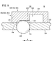
図4に示されるように、第2保持部42は、電極本体46と、磁力でスタッド24を引き付ける磁石部48と、電極チップとして機能するキャップ50と、で構成される。
As shown in FIG. 4, the second holding portion 42 includes an electrode body 46, a magnet portion 48 that attracts the stud 24 by magnetic force, and a cap 50 that functions as an electrode tip.
電極本体46は、金属等の導電部材であり、磁石収納孔52と、1以上の横孔54と、を有する。電極本体46は、第1保持部40の先端部に取り付けられ、第1保持部40の導電部材に接続される。磁石収納孔52は、電極本体46の先端面56に形成される先端開口56aから先端開口56aよりも基端側に形成される底部58まで、電極本体46の軸線に沿って形成される。横孔54は、電極本体46の側壁60に形成される側壁開口60aから底部58まで、電極本体46の径に沿って形成される。
The electrode body 46 is a conductive member such as metal, and has a magnet storage hole 52 and one or more horizontal holes 54. The electrode body 46 is attached to the tip of the first holding portion 40 and is connected to the conductive member of the first holding portion 40. The magnet accommodating hole 52 is formed along the axis of the electrode body 46 from the tip opening 56a formed on the tip surface 56 of the electrode body 46 to the bottom 58 formed on the base end side of the tip opening 56a. The lateral hole 54 is formed along the diameter of the electrode body 46 from the side wall opening 60a formed in the side wall 60 of the electrode body 46 to the bottom portion 58.
磁石部48は、円筒形の磁石62と、磁石62の全面を覆う非磁性体64と、を有する。非磁性体64は、中心を貫通する第1スタッド保持孔66を有する。磁石部48は、電極本体46の磁石収納孔52に嵌合され、横孔54を塞がない位置で保持される。なお、磁石部48に冷却媒体を流す流路が設けられてもよい。
The magnet portion 48 has a cylindrical magnet 62 and a non-magnetic body 64 that covers the entire surface of the magnet 62. The non-magnetic material 64 has a first stud holding hole 66 penetrating the center. The magnet portion 48 is fitted in the magnet storage hole 52 of the electrode body 46, and is held at a position where the lateral hole 54 is not blocked. The magnet portion 48 may be provided with a flow path through which the cooling medium flows.
キャップ50は、金属等の導電部材である。キャップ50は、先端に形成されるキャップ開口68と、キャップ開口68に接続されてキャップ50の中心を貫通する第2スタッド保持孔70と、を有する。キャップ50は、電極本体46の先端部の側壁60にねじ込まれ、電極本体46の先端及び磁石収納孔52に嵌合された磁石部48の非磁性体64の先端に当接する。
The cap 50 is a conductive member such as metal. The cap 50 has a cap opening 68 formed at the tip thereof and a second stud holding hole 70 connected to the cap opening 68 and penetrating the center of the cap 50. The cap 50 is screwed into the side wall 60 at the tip of the electrode body 46 and comes into contact with the tip of the electrode body 46 and the tip of the non-magnetic body 64 of the magnet portion 48 fitted in the magnet storage hole 52.
第1スタッド保持孔66と第2スタッド保持孔70は、互いの軸線を一致させて並んでスタッド保持孔72を構成する。スタッド保持孔72は、底部58の位置で横孔54に繋がる。従って、キャップ開口68(第1開口)と側壁開口60a(第2開口)は、スタッド保持孔72と横孔54を介して連通する。スタッド保持孔72の径は、スタッド24の軸部26の径よりも大きい。また、キャップ開口68の径は、スタッド24のフランジ28の径よりも小さい。スタッド24は、軸部26がスタッド保持孔72に挿入され、フランジ28がキャップ50の先端に当接した状態で、磁石62の磁力で引っ張られる。
The first stud holding hole 66 and the second stud holding hole 70 form the stud holding hole 72 by aligning their axes with each other. The stud holding hole 72 is connected to the lateral hole 54 at the position of the bottom portion 58. Therefore, the cap opening 68 (first opening) and the side wall opening 60a (second opening) communicate with each other through the stud holding hole 72 and the lateral hole 54. The diameter of the stud holding hole 72 is larger than the diameter of the shaft portion 26 of the stud 24. Further, the diameter of the cap opening 68 is smaller than the diameter of the flange 28 of the stud 24. The stud 24 is pulled by the magnetic force of the magnet 62 with the shaft portion 26 inserted into the stud holding hole 72 and the flange 28 in contact with the tip of the cap 50.
第2電極38の先端と対向する位置には、第2電極38のキャップ開口68(第1開口)からスタッド保持孔72の内部にエアを噴射するエア噴射部が設けられる。上述したように、第2電極38は、電極切替装置36の動作に応じてその先端をスタッド供給装置22に向ける。[4]で説明するように、スタッド供給装置22は、スタッド24をエアの圧力を利用してスタッド保持孔72に挿入するエア搬送式のスタッド供給部である。本実施形態では、スタッド供給装置22がエア噴射部として使用される。
At a position facing the tip of the second electrode 38, an air injection portion for injecting air from the cap opening 68 (first opening) of the second electrode 38 into the stud holding hole 72 is provided. As described above, the tip of the second electrode 38 is directed toward the stud supply device 22 according to the operation of the electrode switching device 36. As described in [4], the stud supply device 22 is an air transport type stud supply unit that inserts the stud 24 into the stud holding hole 72 by utilizing the pressure of air. In this embodiment, the stud supply device 22 is used as an air injection unit.
[3.2.第2電極38の清掃方法]
図5に示されるように、第2電極38の第2保持部42がスタッド供給装置22に向けられると、キャップ開口68とスタッド供給装置22のマガジン80の射出口102は、互いに対向する。スタッド保持孔72にスタッド24が挿入されていない状態で、スタッド供給装置22は、射出口102からキャップ開口68に向けて清掃用エア74を噴射する。清掃用エア74は、キャップ開口68からスタッド保持孔72に流入し、スタッド保持孔72と横孔54を通過し、側壁開口60aから外部に流出する。このとき、清掃用エア74は、スタッド保持孔72と横孔54に溜まる塵76を側壁開口60aから外部に吹き飛ばす。その結果、スタッド保持孔72と横孔54は、塵76を取り除かれて清浄になる。 [3.2. Cleaning method of the second electrode 38]
As shown in FIG. 5, when the second holdingportion 42 of the second electrode 38 is directed toward the stud supply device 22, the cap opening 68 and the ejection port 102 of the magazine 80 of the stud supply device 22 face each other. With the stud 24 not inserted into the stud holding hole 72, the stud supply device 22 injects cleaning air 74 from the injection port 102 toward the cap opening 68. The cleaning air 74 flows into the stud holding hole 72 from the cap opening 68, passes through the stud holding hole 72 and the lateral hole 54, and flows out from the side wall opening 60a to the outside. At this time, the cleaning air 74 blows the dust 76 accumulated in the stud holding hole 72 and the lateral hole 54 to the outside from the side wall opening 60a. As a result, the stud holding hole 72 and the lateral hole 54 are cleaned by removing dust 76.
図5に示されるように、第2電極38の第2保持部42がスタッド供給装置22に向けられると、キャップ開口68とスタッド供給装置22のマガジン80の射出口102は、互いに対向する。スタッド保持孔72にスタッド24が挿入されていない状態で、スタッド供給装置22は、射出口102からキャップ開口68に向けて清掃用エア74を噴射する。清掃用エア74は、キャップ開口68からスタッド保持孔72に流入し、スタッド保持孔72と横孔54を通過し、側壁開口60aから外部に流出する。このとき、清掃用エア74は、スタッド保持孔72と横孔54に溜まる塵76を側壁開口60aから外部に吹き飛ばす。その結果、スタッド保持孔72と横孔54は、塵76を取り除かれて清浄になる。 [3.2. Cleaning method of the second electrode 38]
As shown in FIG. 5, when the second holding
[4.スタッド供給装置22]
[4.1.スタッド供給装置22の構成]
図6~図9を用いてスタッド供給装置22の構成を説明する。本実施形態において、プロジェクション溶接装置12は、2つのスタッド供給装置22を有する。一方のスタッド供給装置22は、第2アーム32(図7)よりも+Z方向側に配置され、第2電極38aにスタッド24を供給する。他方のスタッド供給装置22は、第2アーム32(図7)よりも-Z方向側に配置され、第2電極38bにスタッド24を供給する。 [4. Stud supply device 22]
[4.1. Configuration of stud supply device 22]
The configuration of thestud supply device 22 will be described with reference to FIGS. 6 to 9. In this embodiment, the projection welding device 12 has two stud supply devices 22. One stud supply device 22 is arranged on the + Z direction side with respect to the second arm 32 (FIG. 7), and supplies the stud 24 to the second electrode 38a. The other stud supply device 22 is arranged on the −Z direction side with respect to the second arm 32 (FIG. 7), and supplies the stud 24 to the second electrode 38b.
[4.1.スタッド供給装置22の構成]
図6~図9を用いてスタッド供給装置22の構成を説明する。本実施形態において、プロジェクション溶接装置12は、2つのスタッド供給装置22を有する。一方のスタッド供給装置22は、第2アーム32(図7)よりも+Z方向側に配置され、第2電極38aにスタッド24を供給する。他方のスタッド供給装置22は、第2アーム32(図7)よりも-Z方向側に配置され、第2電極38bにスタッド24を供給する。 [4. Stud supply device 22]
[4.1. Configuration of stud supply device 22]
The configuration of the
スタッド供給装置22は、マガジン80と、複数の切替機構82(第1切替機構82a~第3切替機構82c)と、第1シリンダ84と、第2シリンダ86と、第3シリンダ88と、第1エア噴射部90と、第2エア噴射部92と、を有する。また、第2アーム32の内側の面(第1アーム30側の面)には基台94が固定される。基台94には、支持部材96が固定される。支持部材96は、第2アーム32を跨いで+Z方向側と-Z方向側に張り出し、2つのスタッド供給装置22を支持する。
The stud supply device 22 includes a magazine 80, a plurality of switching mechanisms 82 (first switching mechanism 82a to third switching mechanism 82c), a first cylinder 84, a second cylinder 86, a third cylinder 88, and a first cylinder. It has an air injection unit 90 and a second air injection unit 92. Further, the base 94 is fixed to the inner surface of the second arm 32 (the surface on the first arm 30 side). The support member 96 is fixed to the base 94. The support member 96 projects over the second arm 32 in the + Z direction side and the −Z direction side to support the two stud supply devices 22.
先ず、支持部材96によって支持されるマガジン80について説明する。図8に示されるように、マガジン80は、所定数のスタッド24を収納する筒である。マガジン80は、その軸線がX方向(スタッド24の供給方向)と平行して配置されており、支持部材96によって+X方向及び-X方向に移動可能に支持される。マガジン80は、+X方向側の一端から-X方向側の他端に貫通するマガジン孔98と、マガジン孔98の一端に位置する案内口100と、マガジン孔98の他端に位置する射出口102と、を有する。マガジン孔98のうち、射出口102に近い部分には、射出直前のスタッド24を停止させる停止部104が設けられる。
First, the magazine 80 supported by the support member 96 will be described. As shown in FIG. 8, the magazine 80 is a cylinder that stores a predetermined number of studs 24. The axis of the magazine 80 is arranged parallel to the X direction (supply direction of the stud 24), and the magazine 80 is movably supported in the + X direction and the −X direction by the support member 96. The magazine 80 has a magazine hole 98 penetrating from one end on the + X direction side to the other end on the −X direction side, a guide port 100 located at one end of the magazine hole 98, and an injection port 102 located at the other end of the magazine hole 98. And have. A stop portion 104 for stopping the stud 24 immediately before injection is provided in a portion of the magazine hole 98 near the injection port 102.
マガジン孔98のうち、停止部104よりも案内口100側(+X方向側)には、スタッド24を停止部104に移動させる前に停止させる第1待機部106及び第2待機部108が設けられる。
Of the magazine holes 98, on the guide port 100 side (+ X direction side) of the stop portion 104, a first standby portion 106 and a second standby portion 108 for stopping the stud 24 before moving it to the stop portion 104 are provided. ..
マガジン孔98の径は、スタッド24のフランジ28の径よりも長く、スタッド24の全長よりも短い。また、マガジン孔98の軸線方向の長さは、所定数分のスタッド24の全長を合算した長さよりも長い。従って、マガジン80は、所定数のスタッド24を、マガジン孔98の内部に、停止部104から+X方向側に向けて直列(1列)に整列させて収納することが可能である。また、マガジン80は、スタッド24を案内口100から入れて射出口102から出すことが可能である。マガジン80の先端には、停止部104に停止するスタッド24の先端を検出するマガジンセンサ110が設けられる。マガジンセンサ110は、例えば光電センサである。
The diameter of the magazine hole 98 is longer than the diameter of the flange 28 of the stud 24 and shorter than the total length of the stud 24. Further, the length of the magazine hole 98 in the axial direction is longer than the total length of the studs 24 for a predetermined number of minutes. Therefore, the magazine 80 can store a predetermined number of studs 24 in series (one row) from the stop portion 104 toward the + X direction inside the magazine hole 98. Further, the magazine 80 can insert the stud 24 through the guide port 100 and eject it from the injection port 102. At the tip of the magazine 80, a magazine sensor 110 that detects the tip of the stud 24 that stops at the stop portion 104 is provided. The magazine sensor 110 is, for example, a photoelectric sensor.
図9に示されるように、マガジン80は、停止部104の位置にマガジン外壁112からマガジン内壁114にかけて貫通する複数のマガジン貫通孔116を有する。複数のマガジン貫通孔116は、停止部104に複数設けられる。複数のマガジン貫通孔116は、停止部104の断面(マガジン80の軸線と直交する断面)の周方向に並べられる。また、マガジン80は、第1待機部106の位置及び第2待機部108の位置に停止部104と同じ形態のマガジン貫通孔116を有する。第1待機部106と第2待機部108の間隔は、スタッド24の長さよりも短い。
As shown in FIG. 9, the magazine 80 has a plurality of magazine through holes 116 penetrating from the magazine outer wall 112 to the magazine inner wall 114 at the position of the stop portion 104. A plurality of magazine through holes 116 are provided in the stop portion 104. The plurality of magazine through holes 116 are arranged in the circumferential direction of the cross section of the stop portion 104 (the cross section orthogonal to the axis of the magazine 80). Further, the magazine 80 has a magazine through hole 116 having the same shape as the stop portion 104 at the position of the first standby portion 106 and the position of the second standby portion 108. The distance between the first standby unit 106 and the second standby unit 108 is shorter than the length of the stud 24.
停止部104には第1切替機構82aが設けられる。第1切替機構82aは、複数のボール122(図8、図9)と、往復部材124(図6~図9)と、を有する。第1切替機構82aは、停止部104でスタッド24を停止させる状態と通過させる状態とを切り替える。
The stop portion 104 is provided with a first switching mechanism 82a. The first switching mechanism 82a has a plurality of balls 122 (FIGS. 8 and 9) and a reciprocating member 124 (FIGS. 6 to 9). The first switching mechanism 82a switches between a state in which the stud 24 is stopped and a state in which the stud 24 is passed by the stop portion 104.
ボール122は、各マガジン貫通孔116の内部に収納され、マガジン貫通孔116の内部でマガジン80の径方向の外側と内側に移動可能である。ボール122は、マガジン貫通孔116の外壁開口120よりも小さく内壁開口118よりも大きい。ボール122の外側端部が外壁開口120の近傍位置にあるとき、ボール122の一部は、内壁開口118からマガジン孔98の内部に突出する。
The balls 122 are housed inside each magazine through hole 116, and can move inside and outside the magazine 80 in the radial direction inside the magazine through hole 116. The ball 122 is smaller than the outer wall opening 120 of the magazine through hole 116 and larger than the inner wall opening 118. When the outer end of the ball 122 is in the vicinity of the outer wall opening 120, a part of the ball 122 projects from the inner wall opening 118 into the magazine hole 98.
往復部材124は、円筒形の部材である。往復部材124は、マガジン外壁112の周囲に設けられ、マガジン外壁112に沿って+X方向及び-X方向に摺動可能である。往復部材124は、マガジン外壁112と対向する内周面126に、周回する凹部128を有する。凹部128は、+X方向側に径が大きい大径部130を有し、-X方向側に径が小さい小径部132を有する。
The reciprocating member 124 is a cylindrical member. The reciprocating member 124 is provided around the magazine outer wall 112 and can slide in the + X direction and the −X direction along the magazine outer wall 112. The reciprocating member 124 has a recess 128 that circulates on the inner peripheral surface 126 that faces the outer wall 112 of the magazine. The recess 128 has a large diameter portion 130 having a large diameter on the + X direction side and a small diameter portion 132 having a small diameter on the −X direction side.
第2切替機構82bは、第1待機部106でスタッド24を停止させる状態と通過させる状態とを切り替える。第3切替機構82cは、第2待機部108でスタッド24を停止させる状態と通過させる状態とを切り替える。第2切替機構82bと第3切替機構82cの構造及び動作は、第1切替機構82aの構造及び動作と同じである。
The second switching mechanism 82b switches between a state in which the stud 24 is stopped and a state in which the stud 24 is passed by the first standby unit 106. The third switching mechanism 82c switches between a state in which the stud 24 is stopped and a state in which the stud 24 is passed by the second standby unit 108. The structure and operation of the second switching mechanism 82b and the third switching mechanism 82c are the same as the structure and operation of the first switching mechanism 82a.
切替機構82は次のように動作する。ボール122は、往復部材124が-X方向に移動し、往復部材124の大径部130がマガジン貫通孔116の外壁開口120と正対する場合に、大径部130とマガジン貫通孔116との間で移動することが可能となる。このとき、複数のボール122は、マガジン孔98(図8)のサイズをスタッド24のフランジ28の径よりも大きくすることが可能となる。すると、スタッド24は、複数のボール122を外側に押して停止部104の径を広げるため、停止部104を通過することが可能となる。
The switching mechanism 82 operates as follows. The ball 122 is between the large diameter portion 130 and the magazine through hole 116 when the reciprocating member 124 moves in the −X direction and the large diameter portion 130 of the reciprocating member 124 faces the outer wall opening 120 of the magazine through hole 116. It becomes possible to move with. At this time, the plurality of balls 122 can make the size of the magazine hole 98 (FIG. 8) larger than the diameter of the flange 28 of the stud 24. Then, the stud 24 pushes the plurality of balls 122 outward to widen the diameter of the stop portion 104, so that the stud 24 can pass through the stop portion 104.
ボール122は、往復部材124が+X方向に移動し、往復部材124の小径部132がマガジン貫通孔116の外壁開口120と正対する場合に、小径部132の周面に当接する。その結果、ボール122は、マガジン貫通孔116の内壁開口118からマガジン孔98の内部に一部を突出させた状態で、往復部材124により移動を規制される。すると、スタッド24は、複数のボール122を外側に押すことができなくなるため、停止部104を通過することが不可となる。
The ball 122 comes into contact with the peripheral surface of the small diameter portion 132 when the reciprocating member 124 moves in the + X direction and the small diameter portion 132 of the reciprocating member 124 faces the outer wall opening 120 of the magazine through hole 116. As a result, the movement of the ball 122 is restricted by the reciprocating member 124 in a state where a part of the ball 122 protrudes from the inner wall opening 118 of the magazine through hole 116 into the magazine hole 98. Then, the stud 24 cannot push the plurality of balls 122 to the outside, so that the stud 24 cannot pass through the stop portion 104.
図6、図7に戻り、スタッド供給装置22の構成の説明を続ける。第1シリンダ84は、第1ロッド134を+X方向及び-X方向に動作させる流体圧シリンダである。第1シリンダ84は、第1切替機構82a~第3切替機構82cよりも+X方向側に配置され、マガジン80に連結される。第1ロッド134は、第1シリンダ84から-X方向に延びており、第1切替機構82aの往復部材124と第3切替機構82cの往復部材124に接続される。第1シリンダ84は、第1切替機構82a及び第3切替機構82cを同時に動作させる。
Returning to FIGS. 6 and 7, the explanation of the configuration of the stud supply device 22 will be continued. The first cylinder 84 is a fluid pressure cylinder that operates the first rod 134 in the + X direction and the −X direction. The first cylinder 84 is arranged on the + X direction side of the first switching mechanism 82a to the third switching mechanism 82c and is connected to the magazine 80. The first rod 134 extends from the first cylinder 84 in the −X direction and is connected to the reciprocating member 124 of the first switching mechanism 82a and the reciprocating member 124 of the third switching mechanism 82c. The first cylinder 84 operates the first switching mechanism 82a and the third switching mechanism 82c at the same time.
第2シリンダ86は、第2ロッド136を+X方向及び-X方向に動作させる流体圧シリンダである。第2シリンダ86は、第1切替機構82a~第3切替機構82cよりも+X方向側に配置され、マガジン80に固定される。第2ロッド136は、第2シリンダ86から-X方向に延びており、第2切替機構82bの往復部材124に接続される。第2シリンダ86は、第2切替機構82bを第1切替機構82a及び第3切替機構82cとは別に動作させる。
The second cylinder 86 is a fluid pressure cylinder that operates the second rod 136 in the + X direction and the −X direction. The second cylinder 86 is arranged on the + X direction side of the first switching mechanism 82a to the third switching mechanism 82c and is fixed to the magazine 80. The second rod 136 extends from the second cylinder 86 in the −X direction and is connected to the reciprocating member 124 of the second switching mechanism 82b. The second cylinder 86 operates the second switching mechanism 82b separately from the first switching mechanism 82a and the third switching mechanism 82c.
第3シリンダ88は、第3ロッド138を+X方向及び-X方向に動作させる流体圧シリンダである。第3シリンダ88は、支持部材96の-X方向側の面に固定される。第3ロッド138は、支持部材96を貫通して+X方向に延びており、マガジン80の基端部に固定される連結プレート140の-X方向側の面に接続される。一方、連結プレート140の+X方向側の面には第1ガイドシャフト142が接続される。
The third cylinder 88 is a fluid pressure cylinder that operates the third rod 138 in the + X direction and the −X direction. The third cylinder 88 is fixed to the surface of the support member 96 on the −X direction side. The third rod 138 penetrates the support member 96 and extends in the + X direction, and is connected to the surface of the connecting plate 140 fixed to the base end portion of the magazine 80 on the −X direction side. On the other hand, the first guide shaft 142 is connected to the surface of the connecting plate 140 on the + X direction side.
第1ガイドシャフト142は、連結プレート140から+X方向に延びて、後述する第2エア噴射部92の台座158に接続される。第1ガイドシャフト142は、支持部材96の+X方向側の端部に固定されるガイド部材144によって+X方向及び-X方向に移動自在に支持される。第3シリンダ88は、連結プレート140に連結される部材、具体的には、マガジン80とそこに連結される各構成(各切替機構82、第1シリンダ84、第2シリンダ86、第1エア噴射部90等)と、台座158に連結される各構成(第2エア噴射部92)を、支持部材96を基準にして、+X方向及び-X方向に動作させる。
The first guide shaft 142 extends from the connecting plate 140 in the + X direction and is connected to the pedestal 158 of the second air injection unit 92, which will be described later. The first guide shaft 142 is movably supported in the + X direction and the −X direction by the guide member 144 fixed to the end of the support member 96 on the + X direction side. The third cylinder 88 is a member connected to the connecting plate 140, specifically, a magazine 80 and each configuration connected to the magazine 80 (each switching mechanism 82, the first cylinder 84, the second cylinder 86, the first air injection). (Part 90, etc.) and each configuration (second air injection part 92) connected to the pedestal 158 are operated in the + X direction and the −X direction with reference to the support member 96.
図8に示されるように、第1エア噴射部90は、マガジン80の停止部104と第1待機部106との間に設けられる。第1エア噴射部90は、マガジン外壁112を周回するエア供給路146を有する。第1エア噴射部90は、エアポンプを有するエア供給回路(不図示)に接続される。一方、マガジン80には、マガジン外壁112からマガジン内壁114にかけてエア供給孔148が形成される。エア供給孔148は、複数設けられる。エア供給孔148は、エア供給路146に連通する。エア供給孔148は、下流側の流路が上流側の流路よりも-X方向側に位置する構造である。このため、第1エア噴射部90は、エア供給路146からエア供給孔148に流入するエアを、マガジン孔98の内部で-X方向に向けて噴射する。
As shown in FIG. 8, the first air injection unit 90 is provided between the stop unit 104 of the magazine 80 and the first standby unit 106. The first air injection unit 90 has an air supply path 146 that goes around the magazine outer wall 112. The first air injection unit 90 is connected to an air supply circuit (not shown) having an air pump. On the other hand, in the magazine 80, an air supply hole 148 is formed from the magazine outer wall 112 to the magazine inner wall 114. A plurality of air supply holes 148 are provided. The air supply hole 148 communicates with the air supply path 146. The air supply hole 148 has a structure in which the flow path on the downstream side is located on the −X direction side with respect to the flow path on the upstream side. Therefore, the first air injection unit 90 injects the air flowing into the air supply hole 148 from the air supply path 146 toward the −X direction inside the magazine hole 98.
第2エア噴射部92は、マガジン80の基端よりも+X方向側に設けられる。第2エア噴射部92は、エアポンプを有するエア供給回路(不図示)に接続される。第2エア噴射部92は、ノズル150をマガジン80の案内口100に近接させる。このため、第2エア噴射部92は、エアを、ノズル150からマガジン孔98の内部に向けて噴射する。第2エア噴射部92は、+Z方向に延びる噴射部ブラケット152を有する。
The second air injection unit 92 is provided on the + X direction side of the base end of the magazine 80. The second air injection unit 92 is connected to an air supply circuit (not shown) having an air pump. The second air injection unit 92 brings the nozzle 150 close to the guide port 100 of the magazine 80. Therefore, the second air injection unit 92 injects air from the nozzle 150 toward the inside of the magazine hole 98. The second air injection unit 92 has an injection unit bracket 152 extending in the + Z direction.
第2ガイドシャフト154は、Y方向と平行し、コイルばね156及び台座158に形成される孔に挿通される。第2ガイドシャフト154の+Y方向側の端部は噴射部ブラケット152に固定され、第2ガイドシャフト154の-Y方向側の端部は台座158よりも-Y方向側で停止部材160に固定される。停止部材160は、第2ガイドシャフト154が挿通される台座158の孔よりも大きいため、第2ガイドシャフト154が孔から抜けることはない。コイルばね156は、噴射部ブラケット152の-Y方向側の端面と台座158の+Y方向側の端面に当接する。
The second guide shaft 154 is parallel to the Y direction and is inserted into the holes formed in the coil spring 156 and the pedestal 158. The end of the second guide shaft 154 on the + Y direction side is fixed to the injection portion bracket 152, and the end of the second guide shaft 154 on the −Y direction side is fixed to the stop member 160 on the −Y direction side of the pedestal 158. To. Since the stop member 160 is larger than the hole of the pedestal 158 through which the second guide shaft 154 is inserted, the second guide shaft 154 does not come out of the hole. The coil spring 156 comes into contact with the end face of the injection portion bracket 152 on the −Y direction side and the end face of the pedestal 158 on the + Y direction side.
このような構造により、第2エア噴射部92は、ノズル150をマガジン80の基端に近接させた状態で停止し、マガジン80のマガジン孔98にエアを供給する。また、第2エア噴射部92は、-Y方向に押されることでコイルばね156を圧縮させて-Y方向側に移動することが可能である。この状態で、マガジン80の案内口100は、第2エア噴射部92で遮られないため、マガジン80のマガジン孔98に対するスタッド24の充填作業が可能になる。
With such a structure, the second air injection unit 92 stops with the nozzle 150 close to the base end of the magazine 80, and supplies air to the magazine hole 98 of the magazine 80. Further, the second air injection unit 92 can compress the coil spring 156 and move in the −Y direction by being pushed in the −Y direction. In this state, the guide port 100 of the magazine 80 is not blocked by the second air injection unit 92, so that the stud 24 can be filled into the magazine hole 98 of the magazine 80.
マガジン孔98に対するスタッド24の充填作業は、スタッド充填装置14(図1等)によって行われる。スタッド供給装置22とスタッド充填装置14の位置ずれを防止するために、スタッド供給装置22には、第1雄部162と第1雌部164が設けられる。第1雄部162は、基台94に固定されており、一方のスタッド供給装置22のマガジン80と他方のスタッド供給装置22のマガジン80との間から+Y方向側に突出する。第1雌部164は、支持部材96の+Y方向側の面に固定される。スタッド24の充填作業については[5.2]で説明する。
The work of filling the stud 24 into the magazine hole 98 is performed by the stud filling device 14 (FIG. 1 and the like). In order to prevent the stud supply device 22 and the stud filling device 14 from being misaligned, the stud supply device 22 is provided with a first male portion 162 and a first female portion 164. The first male portion 162 is fixed to the base 94 and projects in the + Y direction from between the magazine 80 of one stud supply device 22 and the magazine 80 of the other stud supply device 22. The first female portion 164 is fixed to the surface of the support member 96 on the + Y direction side. The filling work of the stud 24 will be described in [5.2].
[4.2.スタッド供給手順]
図10A~図10Eを用いてスタッド供給装置22から第2電極38に対してスタッド24を供給する手順、及び、マガジン孔98の内部でスタッド24を先端側に送る手順を説明する。以下の説明では、各切替機構82(82a~82c)は、往復部材124を動作させて、ボール122の移動を規制する状態とボール122の移動の規制を解除する状態とを切り替える。以下では、切替機構82がボール122の移動を規制する状態をロック状態と称し、切替機構82がボール122の移動の規制を解除する状態をロック解除状態と称する。なお、ここではマガジン孔98に3つのスタッド24が収納される状態を説明する。そして、3つのスタッド24を先頭から順に、第1スタッド24a、第2スタッド24b、第3スタッド24cとも称する。 [4.2. Stud supply procedure]
A procedure for supplying thestud 24 from the stud supply device 22 to the second electrode 38 and a procedure for feeding the stud 24 to the tip side inside the magazine hole 98 will be described with reference to FIGS. 10A to 10E. In the following description, each switching mechanism 82 (82a to 82c) operates the reciprocating member 124 to switch between a state in which the movement of the ball 122 is restricted and a state in which the restriction on the movement of the ball 122 is released. Hereinafter, the state in which the switching mechanism 82 restricts the movement of the ball 122 is referred to as a locked state, and the state in which the switching mechanism 82 releases the restriction on the movement of the ball 122 is referred to as an unlocked state. Here, a state in which the three studs 24 are housed in the magazine hole 98 will be described. Then, the three studs 24 are also referred to as a first stud 24a, a second stud 24b, and a third stud 24c in order from the beginning.
図10A~図10Eを用いてスタッド供給装置22から第2電極38に対してスタッド24を供給する手順、及び、マガジン孔98の内部でスタッド24を先端側に送る手順を説明する。以下の説明では、各切替機構82(82a~82c)は、往復部材124を動作させて、ボール122の移動を規制する状態とボール122の移動の規制を解除する状態とを切り替える。以下では、切替機構82がボール122の移動を規制する状態をロック状態と称し、切替機構82がボール122の移動の規制を解除する状態をロック解除状態と称する。なお、ここではマガジン孔98に3つのスタッド24が収納される状態を説明する。そして、3つのスタッド24を先頭から順に、第1スタッド24a、第2スタッド24b、第3スタッド24cとも称する。 [4.2. Stud supply procedure]
A procedure for supplying the
図10Aは、マガジン孔98に対してスタッド24が充填される第1工程を示す。第2シリンダ86(図6等)は、第2切替機構82bの往復部材124を+X方向側に配置して、第2切替機構82bをロック状態にする。第1シリンダ84は、第3切替機構82cの往復部材124を-X方向側に配置して、第3切替機構82cをロック解除状態にする。この状態でマガジン孔98の基端から所定数(複数)のスタッド24が充填されると、第3切替機構82cのボール122は、第1スタッド24aに押されて外側に移動する。このため、第1スタッド24aは、第2待機部108を通過する。また、第2切替機構82bのボール122は、第1スタッド24aのフランジ28に当接する。このため、第1スタッド24aは、第1待機部106で停止する。このとき、第2スタッド24bは、第1スタッド24aに当接し、第2待機部108よりも+X方向側で停止する。その結果、図10Aに示される状態になる。
FIG. 10A shows the first step in which the stud 24 is filled in the magazine hole 98. In the second cylinder 86 (FIG. 6 and the like), the reciprocating member 124 of the second switching mechanism 82b is arranged on the + X direction side to lock the second switching mechanism 82b. In the first cylinder 84, the reciprocating member 124 of the third switching mechanism 82c is arranged on the −X direction side to bring the third switching mechanism 82c into the unlocked state. When a predetermined number (plurality) of studs 24 are filled from the base end of the magazine hole 98 in this state, the balls 122 of the third switching mechanism 82c are pushed by the first studs 24a and move outward. Therefore, the first stud 24a passes through the second standby unit 108. Further, the ball 122 of the second switching mechanism 82b comes into contact with the flange 28 of the first stud 24a. Therefore, the first stud 24a stops at the first standby unit 106. At this time, the second stud 24b comes into contact with the first stud 24a and stops on the + X direction side of the second standby portion 108. As a result, the state shown in FIG. 10A is obtained.
図10Bは、第1工程の次に行われる第2工程を示す。第1シリンダ84(図6等)は、第1切替機構82a及び第3切替機構82cの往復部材124を+X方向側に配置して、第1切替機構82a及び第3切替機構82cをロック状態にする。その結果、図10Bに示される状態になる。このとき、各スタッド24の停止位置は変わらない。この状態で、第2エア噴射部92(図6等)からマガジン孔98の内部にエアが噴射される。各スタッド24は、エアによって姿勢を矯正され、先端をエアの流れ方向、すなわち-X方向に向ける。
FIG. 10B shows a second step performed after the first step. In the first cylinder 84 (FIG. 6 and the like), the reciprocating member 124 of the first switching mechanism 82a and the third switching mechanism 82c is arranged on the + X direction side, and the first switching mechanism 82a and the third switching mechanism 82c are locked. To do. As a result, the state shown in FIG. 10B is obtained. At this time, the stop position of each stud 24 does not change. In this state, air is injected into the magazine hole 98 from the second air injection unit 92 (FIG. 6 and the like). The posture of each stud 24 is corrected by air, and the tip thereof is directed in the air flow direction, that is, in the −X direction.
図10Cは、第2工程の次に行われる第3工程を示す。第2シリンダ86は、第2切替機構82bの往復部材124を-X方向側に配置して、第2切替機構82bをロック解除状態にする。第2切替機構82bのボール122は、エアによって推進力を与えられた第1スタッド24aに押されて外側に移動する。このため、第1スタッド24aは、第1待機部106を通過し、停止部104まで進む。第1切替機構82aのボール122は、第1スタッド24aのフランジ28に当接する。このため、第1スタッド24aは、停止部104で停止する。更に、エアによって推進力を与えられた第2スタッド24bは、第2待機部108まで進む。第3切替機構82cのボール122は、第2スタッド24bのフランジ28に当接する。このため、第2スタッド24bは、第2待機部108で停止する。この状態で、第1エア噴射部90からマガジン孔98の内部にエアが噴射される。第1スタッド24aは、エアによって姿勢を矯正され、先端をエアの流れ方向、すなわち-X方向に向ける。その結果、図10Cに示される状態になる。
FIG. 10C shows a third step performed after the second step. In the second cylinder 86, the reciprocating member 124 of the second switching mechanism 82b is arranged on the −X direction side to bring the second switching mechanism 82b into the unlocked state. The ball 122 of the second switching mechanism 82b is pushed by the first stud 24a provided with propulsive force by air and moves outward. Therefore, the first stud 24a passes through the first standby unit 106 and proceeds to the stop unit 104. The ball 122 of the first switching mechanism 82a comes into contact with the flange 28 of the first stud 24a. Therefore, the first stud 24a stops at the stop portion 104. Further, the second stud 24b to which the propulsion force is given by the air advances to the second standby portion 108. The ball 122 of the third switching mechanism 82c comes into contact with the flange 28 of the second stud 24b. Therefore, the second stud 24b stops at the second standby unit 108. In this state, air is injected from the first air injection unit 90 into the magazine hole 98. The posture of the first stud 24a is corrected by the air, and the tip thereof is directed in the air flow direction, that is, in the −X direction. As a result, the state shown in FIG. 10C is obtained.
図10Dは、第3工程の次に行われる第4工程を示す。第2シリンダ86は、第2切替機構82bの往復部材124を+X方向側に配置して、第2切替機構82bをロック状態にする。その結果、図10Dに示される状態になる。このとき、各スタッド24の停止位置は変わらない。
FIG. 10D shows a fourth step performed after the third step. The second cylinder 86 arranges the reciprocating member 124 of the second switching mechanism 82b on the + X direction side to lock the second switching mechanism 82b. As a result, the state shown in FIG. 10D is obtained. At this time, the stop position of each stud 24 does not change.
図10Eは、第4工程の次に行われる第5工程を示す。第1シリンダ84は、第1切替機構82a及び第3切替機構82cの往復部材124を-X方向側に配置して、第1切替機構82a及び第3切替機構82cをロック解除状態にする。第1切替機構82aのボール122は、エアによって推進力を与えられた第1スタッド24aに押されて外側に移動する。このため、第1スタッド24aは、停止部104を通過し、射出口102から射出される。また、第2切替機構82bのボール122は、第2スタッド24bのフランジ28に当接する。このため、第2スタッド24bは、第1待機部106で停止する。このとき、第3スタッド24cは、第2スタッド24bに当接し、第2待機部108よりも+X方向側で停止する。その結果、図10Eに示される状態になる。この状態は図10Aに示される第1工程の状態と同じである。従って、その後は、第2工程~第5工程の処理が繰り返し行われる。
FIG. 10E shows a fifth step performed after the fourth step. In the first cylinder 84, the reciprocating member 124 of the first switching mechanism 82a and the third switching mechanism 82c is arranged on the −X direction side to bring the first switching mechanism 82a and the third switching mechanism 82c into the unlocked state. The ball 122 of the first switching mechanism 82a is pushed by the first stud 24a provided with propulsive force by air and moves outward. Therefore, the first stud 24a passes through the stop portion 104 and is ejected from the injection port 102. Further, the ball 122 of the second switching mechanism 82b comes into contact with the flange 28 of the second stud 24b. Therefore, the second stud 24b stops at the first standby unit 106. At this time, the third stud 24c comes into contact with the second stud 24b and stops on the + X direction side of the second standby portion 108. As a result, the state shown in FIG. 10E is obtained. This state is the same as the state of the first step shown in FIG. 10A. Therefore, after that, the processes of the second step to the fifth step are repeated.
[5.スタッド充填装置14]
[5.1.スタッド充填装置14の構成]
図1、図11~図16を用いてスタッド充填装置14の構成を説明する。図1に示されるように、スタッド充填装置14は、支持台170によって支持されており、鉛直方向に延びる軸を中心にして回転し、スタッド送り装置16からスタッド24を受け取る位置(図15)と、スタッド供給装置22にスタッド24を充填する位置(図16)との間で移動することが可能である。 [5. Stud filling device 14]
[5.1. Configuration of stud filling device 14]
The configuration of thestud filling device 14 will be described with reference to FIGS. 1 and 11 to 16. As shown in FIG. 1, the stud filling device 14 is supported by a support base 170, rotates about an axis extending in the vertical direction, and receives a stud 24 from the stud feeding device 16 (FIG. 15). , It is possible to move between the position where the stud supply device 22 is filled with the stud 24 (FIG. 16).
[5.1.スタッド充填装置14の構成]
図1、図11~図16を用いてスタッド充填装置14の構成を説明する。図1に示されるように、スタッド充填装置14は、支持台170によって支持されており、鉛直方向に延びる軸を中心にして回転し、スタッド送り装置16からスタッド24を受け取る位置(図15)と、スタッド供給装置22にスタッド24を充填する位置(図16)との間で移動することが可能である。 [5. Stud filling device 14]
[5.1. Configuration of stud filling device 14]
The configuration of the
図11、図12に示されるように、スタッド充填装置14は、支持台170によって支持される鉛直プレート172に取り付けられる複数の部品及びそれらの部品に取り付けられる複数の部品で構成される。鉛直プレート172には、下から順に、第2雌部174、第2雄部176、2つの第1ブラケット178、2つの水平プレート180、2つの第2ブラケット182が取り付けられる。
As shown in FIGS. 11 and 12, the stud filling device 14 is composed of a plurality of parts attached to the vertical plate 172 supported by the support base 170 and a plurality of parts attached to those parts. A second female portion 174, a second male portion 176, two first brackets 178, two horizontal plates 180, and two second brackets 182 are attached to the vertical plate 172 in this order from the bottom.
第2雌部174、第2雄部176は、鉛直プレート172から前方向に突出する。2つの第1ブラケット178は、鉛直プレート172から前方向に延び、個別にセンサ支持部材184を支持する。センサ支持部材184は、下側チューブセンサ186を支持する。下側チューブセンサ186は、チューブ190の下端よりも下に配置される。2つの水平プレート180は、鉛直プレート172から前方向に延び、個別にチューブ190とローラ支持部192を支持する。水平プレート180には、下方向に延びるピン189がその軸線を中心に回転自在に取り付けられる。ピン189の下端には、第4シリンダ188が固定される。ピン189は、第4シリンダ188を回転自在に支持する。ローラ支持部192は、ローラ194を回転自在に支持する。ローラ194は、チューブ190よりも前方向に突出する。2つの第2ブラケット182は、鉛直プレート172から前方向に延び、個別に上側チューブセンサ196を支持する。
The second female part 174 and the second male part 176 project forward from the vertical plate 172. The two first brackets 178 extend forward from the vertical plate 172 and individually support the sensor support member 184. The sensor support member 184 supports the lower tube sensor 186. The lower tube sensor 186 is located below the lower end of the tube 190. The two horizontal plates 180 extend forward from the vertical plate 172 and individually support the tube 190 and the roller support 192. A pin 189 extending downward is rotatably attached to the horizontal plate 180 about its axis. A fourth cylinder 188 is fixed to the lower end of the pin 189. The pin 189 rotatably supports the fourth cylinder 188. The roller support portion 192 rotatably supports the roller 194. The roller 194 projects forward of the tube 190. The two second brackets 182 extend forward from the vertical plate 172 and individually support the upper tube sensor 196.
チューブ190は、鉛直方向に延びており、水平プレート180で支持される。チューブ190の上端は水平プレート180の上に配置され、チューブ190の下端は水平プレート180の下に配置される。水平プレート180の下に配置されるチューブ190の下端部には、切替機構198が設けられる。一方のチューブ190は、2つのスタッド供給装置22のうちの一方にスタッド24を充填し、他方のチューブ190は、2つのスタッド供給装置22のうちの他方にスタッド24を充填する。
The tube 190 extends in the vertical direction and is supported by the horizontal plate 180. The upper end of the tube 190 is located above the horizontal plate 180 and the lower end of the tube 190 is located below the horizontal plate 180. A switching mechanism 198 is provided at the lower end of the tube 190 arranged below the horizontal plate 180. One tube 190 fills one of the two stud feeders 22 with the stud 24, and the other tube 190 fills the other of the two stud feeders 22 with the stud 24.
切替機構198の外周面には、水平方向に広がるフランジ199が形成される。フランジ199の一部には、ジョイント201の軸部材が挿通される。ジョイント201の軸部材は、鉛直方向に延びる。ジョイント201の後端は、第4シリンダ188から前方向に延びる第4ロッド200の先端に接続される。この構造により、第4シリンダ188が第4ロッド200を前方向又は後方向に移動させると、切替機構198の回転部材226(図14A、図14B)が停止部216(図13A、図13B)の軸心を中心にして一方向又は逆方向に回転する。この際、第4シリンダ188は、ピン189を中心にして回転する。
A flange 199 extending in the horizontal direction is formed on the outer peripheral surface of the switching mechanism 198. The shaft member of the joint 201 is inserted through a part of the flange 199. The shaft member of the joint 201 extends in the vertical direction. The rear end of the joint 201 is connected to the tip of the fourth rod 200 extending forward from the fourth cylinder 188. With this structure, when the fourth cylinder 188 moves the fourth rod 200 forward or backward, the rotating member 226 (FIGS. 14A, 14B) of the switching mechanism 198 of the stop portion 216 (FIGS. 13A, 13B). It rotates in one direction or in the opposite direction around the axis. At this time, the fourth cylinder 188 rotates about the pin 189.
図13A、図13Bに示されるように、チューブ190は、所定数のスタッド24を収納する筒である。チューブ190は、上側の一端から下側の他端に貫通するチューブ孔210と、チューブ孔210の一端に位置する案内口212と、チューブ孔210の他端に位置する排出口214と、を有する。チューブ孔210のうち、排出口214に近い部分には、先頭のスタッド24を停止させる停止部216が設けられる。
As shown in FIGS. 13A and 13B, the tube 190 is a cylinder for accommodating a predetermined number of studs 24. The tube 190 has a tube hole 210 that penetrates from one upper end to the other end of the lower side, a guide port 212 located at one end of the tube hole 210, and a discharge port 214 located at the other end of the tube hole 210. .. A stop portion 216 for stopping the leading stud 24 is provided in a portion of the tube hole 210 close to the discharge port 214.
チューブ孔210の径は、スタッド24のフランジ28の径よりも長く、スタッド24の全長よりも短い。また、チューブ孔210の軸線方向の長さは、所定数分のスタッド24の全長を合算した長さよりも長い。従って、チューブ190は、所定数のスタッド24をチューブ孔210の内部に停止部216から下に向けて直列(1列)に整列させて収納することが可能である。また、チューブ190は、スタッド24を案内口212から入れて排出口214から出すことが可能である。
The diameter of the tube hole 210 is longer than the diameter of the flange 28 of the stud 24 and shorter than the total length of the stud 24. Further, the axial length of the tube hole 210 is longer than the total length of the studs 24 for a predetermined number of minutes. Therefore, the tube 190 can store a predetermined number of studs 24 in series (one row) downward from the stop portion 216 inside the tube hole 210. Further, the tube 190 can insert the stud 24 through the guide port 212 and eject it from the discharge port 214.
チューブ190の下端の下には、停止部216に停止するスタッド24の先端を検出する下側チューブセンサ186が設けられる。また、チューブ190の上端部には、チューブ孔210に収納された所定数のスタッド24のうちの最後尾に位置するスタッド24を検出する上側チューブセンサ196が設けられる。下側チューブセンサ186及び上側チューブセンサ196は、例えば光電センサである。
Below the lower end of the tube 190, a lower tube sensor 186 that detects the tip of the stud 24 that stops at the stop portion 216 is provided. Further, an upper tube sensor 196 for detecting the stud 24 located at the end of a predetermined number of studs 24 housed in the tube hole 210 is provided at the upper end of the tube 190. The lower tube sensor 186 and the upper tube sensor 196 are, for example, photoelectric sensors.
チューブ190は、停止部216の位置にチューブ外壁218からチューブ内壁220にかけて貫通する複数のチューブ貫通孔222を有する。複数のチューブ貫通孔222は、停止部216の断面(チューブ190の軸線と直交する断面)の周方向に並べられる。
The tube 190 has a plurality of tube through holes 222 penetrating from the tube outer wall 218 to the tube inner wall 220 at the position of the stop portion 216. The plurality of tube through holes 222 are arranged in the circumferential direction of the cross section of the stop portion 216 (the cross section orthogonal to the axis of the tube 190).
図14A、図14Bに示されるように、切替機構198は、複数のボール224と、回転部材226と、を有する。切替機構198は、停止部216でスタッド24を停止させる状態と通過させる状態とを切り替える。
As shown in FIGS. 14A and 14B, the switching mechanism 198 has a plurality of balls 224 and a rotating member 226. The switching mechanism 198 switches between a state in which the stud 24 is stopped and a state in which the stud 24 is passed by the stop portion 216.
ボール224は、各チューブ貫通孔222の内部に収納され、チューブ貫通孔222の内部でチューブ190の径方向の外側と内側に移動可能である。ボール224は、チューブ貫通孔222の外壁開口228よりも小さく内壁開口230よりも大きい。ボール224の外側端部が外壁開口228の近傍位置にあるとき、ボール224の一部は、内壁開口230からチューブ孔210の内部に突出する。
The ball 224 is housed inside each tube through hole 222 and can be moved inside and outside the tube 190 in the radial direction inside the tube through hole 222. The ball 224 is smaller than the outer wall opening 228 of the tube through hole 222 and larger than the inner wall opening 230. When the outer end of the ball 224 is in the vicinity of the outer wall opening 228, a portion of the ball 224 projects from the inner wall opening 230 into the tube hole 210.
回転部材226は、円筒形の部材である。回転部材226は、チューブ外壁218の周囲に設けられ、チューブ外壁218に沿ってチューブ190の周方向に摺動可能である。回転部材226は、チューブ外壁218と対向する内周面232に、凹部234を有する。凹部234は、停止部216の断面(チューブ190の軸線と直交する断面)の周方向に並べられる。
The rotating member 226 is a cylindrical member. The rotating member 226 is provided around the tube outer wall 218 and is slidable along the tube outer wall 218 in the circumferential direction of the tube 190. The rotating member 226 has a recess 234 on the inner peripheral surface 232 facing the outer wall 218 of the tube. The recesses 234 are arranged in the circumferential direction of the cross section of the stop portion 216 (the cross section orthogonal to the axis of the tube 190).
切替機構198は次のように動作する。ボール224は、回転部材226が回転し、回転部材226の凹部234がチューブ貫通孔222の外壁開口228と正対する場合に、凹部234とチューブ貫通孔222との間で移動することが可能となる。このとき、複数のボール224は、停止部216のサイズをスタッド24のフランジ28の径よりも大きくすることが可能となる。すると、スタッド24は、複数のボール224を自重で外側に押して停止部216を広げるため、停止部216を通過することが可能となる。
The switching mechanism 198 operates as follows. The ball 224 can move between the recess 234 and the tube through hole 222 when the rotating member 226 rotates and the recess 234 of the rotating member 226 faces the outer wall opening 228 of the tube through hole 222. .. At this time, the plurality of balls 224 can make the size of the stop portion 216 larger than the diameter of the flange 28 of the stud 24. Then, the stud 24 pushes the plurality of balls 224 outward by its own weight to expand the stop portion 216, so that the stud 24 can pass through the stop portion 216.
ボール224は、回転部材226が回転し、回転部材226の凹部234がチューブ貫通孔222の外壁開口228と正対しない場合に、内周面232に当接する。その結果、ボール224は、チューブ貫通孔222の内壁開口230からチューブ孔210の内部に一部を突出させた状態で、回転部材226により移動を規制される。すると、スタッド24は、複数のボール224を外側に押すことができなくなるため、停止部216を通過することが不可となる。
The ball 224 comes into contact with the inner peripheral surface 232 when the rotating member 226 rotates and the recess 234 of the rotating member 226 does not face the outer wall opening 228 of the tube through hole 222. As a result, the movement of the ball 224 is restricted by the rotating member 226 with a part of the ball 224 protruding from the inner wall opening 230 of the tube through hole 222 into the tube hole 210. Then, since the stud 24 cannot push the plurality of balls 224 outward, it cannot pass through the stop portion 216.
[5.2.スタッド充填手順]
図15~図19を用いてスタッド送り装置16からスタッド充填装置14に対してスタッド24を送り、次いでスタッド充填装置14からスタッド供給装置22にスタッド24を供給する手順を説明する。以下の説明では、切替機構198は、回転部材226を動作させて、ボール224の移動を規制する状態とボール224の移動の規制を解除する状態とを切り替える。以下では、切替機構198がボール224の移動を規制する状態をロック状態と称し、切替機構198がボール122の移動の規制を解除する状態をロック解除状態と称する。なお、以下の説明では、制御装置(不図示)が各装置の動作を統括して制御する。 [5.2. Stud filling procedure]
A procedure of feeding thestud 24 from the stud feeding device 16 to the stud filling device 14 and then supplying the stud 24 from the stud filling device 14 to the stud feeding device 22 will be described with reference to FIGS. 15 to 19. In the following description, the switching mechanism 198 operates the rotating member 226 to switch between a state in which the movement of the ball 224 is restricted and a state in which the movement of the ball 224 is released. Hereinafter, the state in which the switching mechanism 198 restricts the movement of the ball 224 is referred to as a locked state, and the state in which the switching mechanism 198 releases the restriction on the movement of the ball 122 is referred to as an unlocked state. In the following description, a control device (not shown) controls the operation of each device in an integrated manner.
図15~図19を用いてスタッド送り装置16からスタッド充填装置14に対してスタッド24を送り、次いでスタッド充填装置14からスタッド供給装置22にスタッド24を供給する手順を説明する。以下の説明では、切替機構198は、回転部材226を動作させて、ボール224の移動を規制する状態とボール224の移動の規制を解除する状態とを切り替える。以下では、切替機構198がボール224の移動を規制する状態をロック状態と称し、切替機構198がボール122の移動の規制を解除する状態をロック解除状態と称する。なお、以下の説明では、制御装置(不図示)が各装置の動作を統括して制御する。 [5.2. Stud filling procedure]
A procedure of feeding the
先ず、第1位置合わせ工程が行われる。支持台170は、図15に示されるように、スタッド送り装置16のスタッド送り部171の下にスタッド充填装置14を配置する。支持台170に設けられるアーム240は、2位置の間で回転することができる。アーム240が一方に旋回すると、スタッド充填装置14は、スタッド送り装置16のスタッド送り部171の下に配置され、スタッド送り装置16からスタッド24を受け取ることができる。
First, the first alignment process is performed. As shown in FIG. 15, the support base 170 arranges the stud filling device 14 under the stud feeding portion 171 of the stud feeding device 16. The arm 240 provided on the support 170 can rotate between two positions. When the arm 240 turns in one direction, the stud filling device 14 is arranged under the stud feeding portion 171 of the stud feeding device 16 and can receive the stud 24 from the stud feeding device 16.
次に、部品収納工程が行われる。第4シリンダ188は、図14Aに示されるように、切替機構198の回転部材226を回転させて、切替機構198をロック状態にする。すると、ボール224は、停止部216の内部に向かって移動して停止部216のサイズをスタッド24のフランジ28よりも小さくする。この状態で、スタッド送り装置16は、所定数のスタッド24をチューブ孔210に向けて落下させる。スタッド24は、先端を下に向けてチューブ孔210に挿入される。図13Aで示されるように、チューブ孔210に所定数のスタッド24が収納されると、上側チューブセンサ196は充填完了状態を検知する。すると、スタッド送り装置16は、スタッド24の供給を停止する。
Next, the parts storage process is performed. As shown in FIG. 14A, the fourth cylinder 188 rotates the rotating member 226 of the switching mechanism 198 to lock the switching mechanism 198. Then, the ball 224 moves toward the inside of the stop portion 216 to make the size of the stop portion 216 smaller than the flange 28 of the stud 24. In this state, the stud feeding device 16 drops a predetermined number of studs 24 toward the tube holes 210. The stud 24 is inserted into the tube hole 210 with its tip facing down. As shown in FIG. 13A, when a predetermined number of studs 24 are housed in the tube holes 210, the upper tube sensor 196 detects the filling completion state. Then, the stud feed device 16 stops the supply of the stud 24.
次に、第2位置合わせ工程が行われる。支持台170は、図16に示されるように、スタッド送り装置16の下からスタッド充填装置14を移動させる。アーム240が他方に旋回すると、スタッド充填装置14は、スタッド送り装置16の下から移動する。
Next, the second alignment process is performed. The support 170 moves the stud filling device 14 from below the stud feeding device 16 as shown in FIG. When the arm 240 turns to the other side, the stud filling device 14 moves from under the stud feeding device 16.
ロボット18は、図17に示されるように、スタッドガン20の先端側(-X方向側)を下に向けて、スタッド供給装置22をスタッド充填装置14に近づける。このとき、ロボット18は、スタッド供給装置22のX方向及びZ方向の位置を調整し、スタッド供給装置22をスタッド充填装置14の前に移動させる。すると、ロボット18は、噴射部ブラケット152をローラ194の正面に配置し、第1雌部164を第2雄部176の正面に配置し、第1雄部162を第2雌部174の正面に配置する。
As shown in FIG. 17, the robot 18 brings the stud supply device 22 closer to the stud filling device 14 with the tip side (−X direction side) of the stud gun 20 facing downward. At this time, the robot 18 adjusts the positions of the stud supply device 22 in the X direction and the Z direction, and moves the stud supply device 22 in front of the stud filling device 14. Then, the robot 18 arranges the injection portion bracket 152 in front of the roller 194, the first female portion 164 in front of the second male portion 176, and the first male portion 162 in front of the second female portion 174. Deploy.
この状態で、ロボット18は、スタッドガン20を徐々に後方向(+Y方向)に移動させて、スタッド供給装置22をスタッド充填装置14に接近させる。すると、噴射部ブラケット152とローラ194が当接する。更に、ロボット18は、スタッドガン20を後方向(+Y方向)に移動させる。すると、図18に示されるように、第2エア噴射部92は、噴射部ブラケット152及び第2ガイドシャフト154と共に前方向(-Y方向)に移動する。このとき、コイルばね156は圧縮される。第1雌部164と第2雄部176が当接し、第1雄部162と第2雌部174が当接すると、ロボット18は、スタッドガン20の移動を停止させる。このとき、チューブ190の軸線とマガジン80の軸線は一致する。
In this state, the robot 18 gradually moves the stud gun 20 in the rear direction (+ Y direction) to bring the stud supply device 22 closer to the stud filling device 14. Then, the injection portion bracket 152 and the roller 194 come into contact with each other. Further, the robot 18 moves the stud gun 20 in the rear direction (+ Y direction). Then, as shown in FIG. 18, the second air injection unit 92 moves in the forward direction (−Y direction) together with the injection unit bracket 152 and the second guide shaft 154. At this time, the coil spring 156 is compressed. When the first female portion 164 and the second male portion 176 come into contact with each other and the first male portion 162 and the second female portion 174 come into contact with each other, the robot 18 stops the movement of the stud gun 20. At this time, the axis of the tube 190 and the axis of the magazine 80 coincide with each other.
この状態で、第3シリンダ88は、図19に示されるように、マガジン80を上方向(+X方向)に移動させる。噴射部ブラケット152は、ローラ194が回転することにより上方向(+X方向)に滑らかに移動する。一方、基台94に固定される第1雄部162と、支持部材96に固定される第1雌部164は、移動しない。
In this state, the third cylinder 88 moves the magazine 80 upward (+ X direction) as shown in FIG. The injection portion bracket 152 moves smoothly in the upward direction (+ X direction) due to the rotation of the roller 194. On the other hand, the first male portion 162 fixed to the base 94 and the first female portion 164 fixed to the support member 96 do not move.
マガジン80が上方向(+X方向)に移動すると、図13Aに示されるように、マガジン80の案内口100は、チューブ190の排出口214に接近する。このとき、マガジン80の案内口100の周辺に形成される光通過孔242の位置と下側チューブセンサ186の位置が合わせられ、下側チューブセンサ186がマガジン80に所定数のスタッド24が収納されたことを検知できるようになる。
When the magazine 80 moves upward (+ X direction), the guide port 100 of the magazine 80 approaches the discharge port 214 of the tube 190, as shown in FIG. 13A. At this time, the position of the light passage hole 242 formed around the guide port 100 of the magazine 80 and the position of the lower tube sensor 186 are aligned, and the lower tube sensor 186 stores a predetermined number of studs 24 in the magazine 80. You will be able to detect that.
次に、部品充填工程が行われる。第4シリンダ188は、図13B及び図14Bに示されるように、切替機構198の回転部材226を回転させて、切替機構198をロック解除状態にする。ボール224は、スタッド24の自重により、停止部216の外部に向かう方向に押される。このため、ボール224は、停止部216の外部に向かって移動して停止部216のサイズをスタッド24のフランジ28よりも大きくする。すると、スタッド24は、先端を下に向けて落下し、マガジン孔98に挿入される。チューブ孔210に収納されていた所定数のスタッド24は、マガジン孔98に供給されると、マガジン80の充填は終了する。
Next, the parts filling process is performed. As shown in FIGS. 13B and 14B, the fourth cylinder 188 rotates the rotating member 226 of the switching mechanism 198 to bring the switching mechanism 198 into the unlocked state. The ball 224 is pushed toward the outside of the stop portion 216 by the weight of the stud 24. Therefore, the ball 224 moves toward the outside of the stop portion 216 to make the size of the stop portion 216 larger than the flange 28 of the stud 24. Then, the stud 24 falls with its tip facing downward and is inserted into the magazine hole 98. When the predetermined number of studs 24 housed in the tube holes 210 are supplied to the magazine holes 98, the filling of the magazine 80 is completed.
[6.変形例]
上述したスタッド供給装置22及びスタッド充填装置14の構成は、他の部品供給装置、部品充填装置に使用可能である。例えば、スタッド供給装置22の構成は、ロボット18のアーム先端にボルトを供給するボルト供給装置に使用することができる。また、スタッド充填装置14の構成は、ボルト供給装置にボルトを充填するボルト充填装置等に使用することができる。 [6. Modification example]
The configuration of thestud supply device 22 and the stud filling device 14 described above can be used for other component supply devices and component filling devices. For example, the configuration of the stud supply device 22 can be used for a bolt supply device that supplies bolts to the tip of the arm of the robot 18. Further, the configuration of the stud filling device 14 can be used for a bolt filling device or the like for filling the bolt supply device with bolts.
上述したスタッド供給装置22及びスタッド充填装置14の構成は、他の部品供給装置、部品充填装置に使用可能である。例えば、スタッド供給装置22の構成は、ロボット18のアーム先端にボルトを供給するボルト供給装置に使用することができる。また、スタッド充填装置14の構成は、ボルト供給装置にボルトを充填するボルト充填装置等に使用することができる。 [6. Modification example]
The configuration of the
[7.実施形態から得られる技術的思想]
上記実施形態から把握しうる技術的思想について、以下に記載する。 [7. Technical Thought Obtained from the Embodiment]
The technical ideas that can be grasped from the above embodiments are described below.
上記実施形態から把握しうる技術的思想について、以下に記載する。 [7. Technical Thought Obtained from the Embodiment]
The technical ideas that can be grasped from the above embodiments are described below.
本発明の第1態様は、
部品送り装置(スタッド送り装置16)から供給される所定数の部品(スタッド24)を一時的に収納し、収納した所定数の前記部品を所定機械(スタッド供給装置22)に充填する部品充填装置(スタッド充填装置14)であって、
鉛直方向に貫通する部品収納孔(チューブ孔210)を有し、前記部品を前記部品収納孔の上端(案内口212)から入れて下端(排出口214)から出すことが可能であり、前記部品収納孔の前記下端側に位置する停止部216で前記部品を停止させることが可能であり、所定数の前記部品を前記部品収納孔の内部で前記停止部216から前記上端側に向けて直列に整列させて収納することが可能である部品収納部(チューブ190)と、
前記部品に当接する位置としない位置との間を移動することが可能な複数の移動体(ボール224)と、複数の前記移動体の移動を規制するロック部(回転部材226)と、を有し、前記停止部216で前記部品を停止させる状態と通過させる状態とを切り替える切替機構198と、
を備える。 The first aspect of the present invention is
A parts filling device that temporarily stores a predetermined number of parts (studs 24) supplied from a parts feeding device (stud feeding device 16) and fills a predetermined number of the stored parts into a predetermined machine (stud feeding device 22). (Stud filling device 14)
It has a component storage hole (tube hole 210) that penetrates in the vertical direction, and the component can be inserted from the upper end (guide port 212) of the component storage hole and ejected from the lower end (discharge port 214). The parts can be stopped by thestop portion 216 located on the lower end side of the storage hole, and a predetermined number of the parts are connected in series from the stop portion 216 toward the upper end side inside the component storage hole. A parts storage unit (tube 190) that can be stored side by side,
It has a plurality of moving bodies (balls 224) capable of moving between a position where the parts are in contact with the parts and a position where the moving bodies are not in contact with the parts, and a lock portion (rotating member 226) for restricting the movement of the plurality of moving bodies. Then, theswitching mechanism 198 for switching between the state in which the component is stopped and the state in which the component is passed by the stop unit 216, and
To be equipped.
部品送り装置(スタッド送り装置16)から供給される所定数の部品(スタッド24)を一時的に収納し、収納した所定数の前記部品を所定機械(スタッド供給装置22)に充填する部品充填装置(スタッド充填装置14)であって、
鉛直方向に貫通する部品収納孔(チューブ孔210)を有し、前記部品を前記部品収納孔の上端(案内口212)から入れて下端(排出口214)から出すことが可能であり、前記部品収納孔の前記下端側に位置する停止部216で前記部品を停止させることが可能であり、所定数の前記部品を前記部品収納孔の内部で前記停止部216から前記上端側に向けて直列に整列させて収納することが可能である部品収納部(チューブ190)と、
前記部品に当接する位置としない位置との間を移動することが可能な複数の移動体(ボール224)と、複数の前記移動体の移動を規制するロック部(回転部材226)と、を有し、前記停止部216で前記部品を停止させる状態と通過させる状態とを切り替える切替機構198と、
を備える。 The first aspect of the present invention is
A parts filling device that temporarily stores a predetermined number of parts (studs 24) supplied from a parts feeding device (stud feeding device 16) and fills a predetermined number of the stored parts into a predetermined machine (stud feeding device 22). (Stud filling device 14)
It has a component storage hole (tube hole 210) that penetrates in the vertical direction, and the component can be inserted from the upper end (guide port 212) of the component storage hole and ejected from the lower end (discharge port 214). The parts can be stopped by the
It has a plurality of moving bodies (balls 224) capable of moving between a position where the parts are in contact with the parts and a position where the moving bodies are not in contact with the parts, and a lock portion (rotating member 226) for restricting the movement of the plurality of moving bodies. Then, the
To be equipped.
上記構成によれば、部品送り装置(スタッド送り装置16)と部品供給装置(スタッド供給装置22)の間に部品充填装置(スタッド充填装置14)が介在する。このため、部品送り装置(スタッド送り装置16)と部品供給装置(スタッド供給装置22)の間に搬送部(ホース)が設けられない。その結果、溶接作業時にスタッドガン20が移動しても、搬送部がワークW等に接触するという不具合は発生しない。
According to the above configuration, the parts filling device (stud filling device 14) is interposed between the parts feeding device (stud feeding device 16) and the parts feeding device (stud feeding device 22). Therefore, a transport unit (hose) is not provided between the parts feeding device (stud feeding device 16) and the parts feeding device (stud feeding device 22). As a result, even if the stud gun 20 moves during the welding work, the problem that the transport portion comes into contact with the work W or the like does not occur.
また、上記構成によれば、部品収納部(チューブ190)が鉛直方向に貫通する部品収納孔(チューブ孔210)の内部に所定数の部品(スタッド24)を直列に整列させて収納するため、部品供給装置(スタッド供給装置22)を部品収納部の下に移動させ、部品を落下させるのみで所定数の部品を部品供給装置に充填することができる。このように、上記構成によれば、スタッドガン20の溶接作業時にワークW等に接触することのない構成で部品送り装置(スタッド送り装置16)から部品供給装置に所定数の部品を充填することができる。
Further, according to the above configuration, a predetermined number of parts (studs 24) are arranged and stored in series inside the parts storage hole (tube hole 210) through which the parts storage portion (tube 190) penetrates in the vertical direction. A predetermined number of parts can be filled in the parts supply device only by moving the parts supply device (stud supply device 22) under the parts storage unit and dropping the parts. As described above, according to the above configuration, the parts feeding device (stud feeding device 16) fills the parts feeding device with a predetermined number of parts so as not to come into contact with the work W or the like during the welding work of the stud gun 20. Can be done.
本発明の第1態様において、
複数の前記移動体(ボール224)は、前記停止部216の断面の周方向に並べられ、前記停止部216の内部に向かって移動して前記停止部216のサイズを前記部品(スタッド24)のサイズよりも小さくして前記部品を停止させること、及び、前記停止部216の外側に向かって移動して前記停止部216のサイズを前記部品のサイズよりも大きくして前記部品を停止させることが可能であり、
前記ロック部(回転部材226)は、複数の前記移動体が前記停止部のサイズを前記部品のサイズよりも小さくした状態で、複数の前記移動体の移動を規制してもよい。 In the first aspect of the present invention
The plurality of moving bodies (balls 224) are arranged in the circumferential direction of the cross section of thestop portion 216, move toward the inside of the stop portion 216, and adjust the size of the stop portion 216 to the size of the component (stud 24). The part can be stopped by making it smaller than the size, and the part can be stopped by moving toward the outside of the stop portion 216 and making the size of the stop portion 216 larger than the size of the part. It is possible and
The lock portion (rotating member 226) may restrict the movement of the plurality of the moving bodies in a state where the plurality of the moving bodies have the size of the stop portion smaller than the size of the parts.
複数の前記移動体(ボール224)は、前記停止部216の断面の周方向に並べられ、前記停止部216の内部に向かって移動して前記停止部216のサイズを前記部品(スタッド24)のサイズよりも小さくして前記部品を停止させること、及び、前記停止部216の外側に向かって移動して前記停止部216のサイズを前記部品のサイズよりも大きくして前記部品を停止させることが可能であり、
前記ロック部(回転部材226)は、複数の前記移動体が前記停止部のサイズを前記部品のサイズよりも小さくした状態で、複数の前記移動体の移動を規制してもよい。 In the first aspect of the present invention
The plurality of moving bodies (balls 224) are arranged in the circumferential direction of the cross section of the
The lock portion (rotating member 226) may restrict the movement of the plurality of the moving bodies in a state where the plurality of the moving bodies have the size of the stop portion smaller than the size of the parts.
本発明の第1態様において、
前記停止部216の位置の前記部品収納部(チューブ190)は、外壁(チューブ外壁218)と内壁(チューブ内壁220)を有する筒であり、
前記筒は、前記外壁から前記内壁にかけて貫通し、前記停止部216の断面の外周に沿って並べられる複数の筒貫通孔(チューブ貫通孔222)を有し、
前記移動体は、前記筒貫通孔の内部で移動可能であるボール224であり、
前記ロック部は、前記筒の前記外壁を囲んで前記筒貫通孔の前記外壁側の開口を覆い、前記停止部216の軸心を中心にして回転可能である回転部材226を有し、
前記回転部材226は、前記筒の前記外壁と対向する内周面232に、複数の前記筒貫通孔同士の間隔と同じ間隔で配置される複数の凹部234を有し、
前記筒貫通孔の前記内壁側の開口(内壁開口230)は、前記ボール224の一部を前記停止部216の内部に突出させることができる大きさ又は形状であり、
前記ボール224は、前記回転部材226の回転位置が前記凹部234を前記筒貫通孔に正対させる位置である場合に、前記凹部234と前記筒貫通孔との間で移動することが可能となり、前記回転部材226の回転位置が前記凹部234を前記筒貫通孔に正対させる位置でない場合に、前記筒貫通孔の前記内壁側の開口から前記停止部216の内部に一部を突出させた状態で、前記回転部材226により移動を規制されてもよい。 In the first aspect of the present invention
The component storage portion (tube 190) at the position of thestop portion 216 is a cylinder having an outer wall (tube outer wall 218) and an inner wall (tube inner wall 220).
The cylinder has a plurality of cylinder through holes (tube through holes 222) that penetrate from the outer wall to the inner wall and are arranged along the outer circumference of the cross section of thestop portion 216.
The moving body is aball 224 that can move inside the cylinder through hole.
The lock portion has a rotatingmember 226 that surrounds the outer wall of the cylinder, covers the opening on the outer wall side of the cylinder through hole, and is rotatable about the axis of the stop portion 216.
The rotatingmember 226 has a plurality of recesses 234 arranged on the inner peripheral surface 232 facing the outer wall of the cylinder at the same intervals as the intervals between the plurality of cylinder through holes.
The opening on the inner wall side of the cylinder through hole (inner wall opening 230) has a size or shape that allows a part of theball 224 to protrude inside the stop portion 216.
Theball 224 can move between the recess 234 and the cylinder through hole when the rotation position of the rotating member 226 is a position where the recess 234 faces the cylinder through hole. A state in which a part of the rotating member 226 is projected from the opening on the inner wall side of the cylinder through hole to the inside of the stop portion 216 when the rotation position of the rotating member 226 is not the position where the recess 234 faces the cylinder through hole. The movement may be restricted by the rotating member 226.
前記停止部216の位置の前記部品収納部(チューブ190)は、外壁(チューブ外壁218)と内壁(チューブ内壁220)を有する筒であり、
前記筒は、前記外壁から前記内壁にかけて貫通し、前記停止部216の断面の外周に沿って並べられる複数の筒貫通孔(チューブ貫通孔222)を有し、
前記移動体は、前記筒貫通孔の内部で移動可能であるボール224であり、
前記ロック部は、前記筒の前記外壁を囲んで前記筒貫通孔の前記外壁側の開口を覆い、前記停止部216の軸心を中心にして回転可能である回転部材226を有し、
前記回転部材226は、前記筒の前記外壁と対向する内周面232に、複数の前記筒貫通孔同士の間隔と同じ間隔で配置される複数の凹部234を有し、
前記筒貫通孔の前記内壁側の開口(内壁開口230)は、前記ボール224の一部を前記停止部216の内部に突出させることができる大きさ又は形状であり、
前記ボール224は、前記回転部材226の回転位置が前記凹部234を前記筒貫通孔に正対させる位置である場合に、前記凹部234と前記筒貫通孔との間で移動することが可能となり、前記回転部材226の回転位置が前記凹部234を前記筒貫通孔に正対させる位置でない場合に、前記筒貫通孔の前記内壁側の開口から前記停止部216の内部に一部を突出させた状態で、前記回転部材226により移動を規制されてもよい。 In the first aspect of the present invention
The component storage portion (tube 190) at the position of the
The cylinder has a plurality of cylinder through holes (tube through holes 222) that penetrate from the outer wall to the inner wall and are arranged along the outer circumference of the cross section of the
The moving body is a
The lock portion has a rotating
The rotating
The opening on the inner wall side of the cylinder through hole (inner wall opening 230) has a size or shape that allows a part of the
The
本発明の第1態様において、
前記ロック部(回転部材226)を動作させる駆動源(第4シリンダ188)を備えてもよい。 In the first aspect of the present invention
A drive source (fourth cylinder 188) for operating the lock portion (rotating member 226) may be provided.
前記ロック部(回転部材226)を動作させる駆動源(第4シリンダ188)を備えてもよい。 In the first aspect of the present invention
A drive source (fourth cylinder 188) for operating the lock portion (rotating member 226) may be provided.
本発明の第1態様において、
前記部品は、プロジェクション溶接でワークWに溶接されるスタッド24であり、
前記所定機械は、プロジェクション溶接装置12に設けられ、溶接電極(第2電極38)に前記スタッド24を供給するスタッド供給装置22であってもよい。 In the first aspect of the present invention
The part is astud 24 that is welded to the work W by projection welding.
The predetermined machine may be astud supply device 22 provided in the projection welding device 12 and supplying the stud 24 to the welding electrode (second electrode 38).
前記部品は、プロジェクション溶接でワークWに溶接されるスタッド24であり、
前記所定機械は、プロジェクション溶接装置12に設けられ、溶接電極(第2電極38)に前記スタッド24を供給するスタッド供給装置22であってもよい。 In the first aspect of the present invention
The part is a
The predetermined machine may be a
本発明の第2態様は、
第1態様の部品充填装置(スタッド充填装置14)を使用して前記部品送り装置(スタッド送り装置16)から供給される所定数の前記部品(スタッド24)を一時的に収納し、収納した所定数の前記部品を前記所定機械(スタッド供給装置22)に充填する部品充填方法であって、
前記部品送り装置の下に前記部品充填装置を配置する第1位置合わせ工程と、
前記移動体(ボール224)を前記停止部216の内部に向かって移動させて前記停止部216のサイズを前記部品のサイズよりも小さくし、前記ロック部(回転部材226)により前記移動体の移動を規制した状態で、所定数の前記部品を前記部品送り装置から前記部品収納孔(チューブ孔210)に供給して、前記部品収納孔に所定数の前記部品を収納する部品収納工程と、
前記部品充填装置の下に前記所定機械を配置する第2位置合わせ工程と、
前記ロック部による前記移動体の移動の規制を解除し、前記部品の自重で前記移動体を前記停止部216の外側に向かって移動させて前記停止部216のサイズを前記部品のサイズよりも大きくし、前記部品を落下させて前記所定機械に充填する部品充填工程と、
を含む。 The second aspect of the present invention is
A predetermined number of the parts (studs 24) supplied from the parts feeding device (stud feeding device 16) are temporarily stored and stored by using the parts filling device (stud filling device 14) of the first aspect. A component filling method for filling the predetermined machine (stud supply device 22) with the number of the components.
A first alignment step of arranging the component filling device under the component feeding device, and
The moving body (ball 224) is moved toward the inside of the stoppingportion 216 to make the size of the stopping portion 216 smaller than the size of the component, and the moving body is moved by the locking portion (rotating member 226). A component storage process in which a predetermined number of the parts are supplied from the component feeding device to the component storage hole (tube hole 210) and the predetermined number of the parts are stored in the component storage hole in a regulated state.
A second alignment step of arranging the predetermined machine under the component filling device, and
The restriction on the movement of the moving body by the lock portion is released, the moving body is moved toward the outside of thestop portion 216 by the weight of the component, and the size of the stop portion 216 is made larger than the size of the component. Then, the parts filling step of dropping the parts and filling the predetermined machine,
including.
第1態様の部品充填装置(スタッド充填装置14)を使用して前記部品送り装置(スタッド送り装置16)から供給される所定数の前記部品(スタッド24)を一時的に収納し、収納した所定数の前記部品を前記所定機械(スタッド供給装置22)に充填する部品充填方法であって、
前記部品送り装置の下に前記部品充填装置を配置する第1位置合わせ工程と、
前記移動体(ボール224)を前記停止部216の内部に向かって移動させて前記停止部216のサイズを前記部品のサイズよりも小さくし、前記ロック部(回転部材226)により前記移動体の移動を規制した状態で、所定数の前記部品を前記部品送り装置から前記部品収納孔(チューブ孔210)に供給して、前記部品収納孔に所定数の前記部品を収納する部品収納工程と、
前記部品充填装置の下に前記所定機械を配置する第2位置合わせ工程と、
前記ロック部による前記移動体の移動の規制を解除し、前記部品の自重で前記移動体を前記停止部216の外側に向かって移動させて前記停止部216のサイズを前記部品のサイズよりも大きくし、前記部品を落下させて前記所定機械に充填する部品充填工程と、
を含む。 The second aspect of the present invention is
A predetermined number of the parts (studs 24) supplied from the parts feeding device (stud feeding device 16) are temporarily stored and stored by using the parts filling device (stud filling device 14) of the first aspect. A component filling method for filling the predetermined machine (stud supply device 22) with the number of the components.
A first alignment step of arranging the component filling device under the component feeding device, and
The moving body (ball 224) is moved toward the inside of the stopping
A second alignment step of arranging the predetermined machine under the component filling device, and
The restriction on the movement of the moving body by the lock portion is released, the moving body is moved toward the outside of the
including.
なお、本発明に係る部品充填装置及び部品充填方法は、上述の実施形態に限らず、本発明の要旨を逸脱することなく、種々の構成を採り得ることはもちろんである。
It should be noted that the component filling device and the component filling method according to the present invention are not limited to the above-described embodiments, and it goes without saying that various configurations can be adopted without departing from the gist of the present invention.
Claims (6)
- 部品送り装置(16)から供給される所定数の部品(24)を一時的に収納し、収納した所定数の前記部品を所定機械(22)に充填する部品充填装置(14)であって、
鉛直方向に貫通する部品収納孔(210)を有し、前記部品を前記部品収納孔の上端(212)から入れて下端(214)から出すことが可能であり、前記部品収納孔の前記下端側に位置する停止部(216)で前記部品を停止させることが可能であり、所定数の前記部品を前記部品収納孔の内部で前記停止部から前記上端側に向けて直列に整列させて収納することが可能である部品収納部(190)と、
前記部品に当接する位置としない位置との間を移動することが可能な複数の移動体(224)と、複数の前記移動体の移動を規制するロック部(226)と、を有し、前記停止部で前記部品を停止させる状態と通過させる状態とを切り替える切替機構(198)と、
を備える、部品充填装置。 A parts filling device (14) that temporarily stores a predetermined number of parts (24) supplied from a parts feeding device (16) and fills a predetermined number of the stored parts into a predetermined machine (22).
It has a component storage hole (210) that penetrates in the vertical direction, and the component can be inserted from the upper end (212) of the component storage hole and exited from the lower end (214), and the lower end side of the component storage hole. It is possible to stop the parts at the stop portion (216) located at the above, and store a predetermined number of the parts in series from the stop portion toward the upper end side inside the component storage hole. With the parts storage (190), which is possible
It has a plurality of moving bodies (224) capable of moving between a position in contact with the component and a position not in contact with the component, and a lock portion (226) for restricting the movement of the plurality of moving bodies. A switching mechanism (198) that switches between a state in which the component is stopped and a state in which the component is passed by the stop portion, and
A parts filling device. - 請求項1に記載の部品充填装置であって、
複数の前記移動体は、前記停止部の断面の周方向に並べられ、前記停止部の内部に向かって移動して前記停止部のサイズを前記部品のサイズよりも小さくして前記部品を停止させること、及び、前記停止部の外側に向かって移動して前記停止部のサイズを前記部品のサイズよりも大きくして前記部品を停止させることが可能であり、
前記ロック部は、複数の前記移動体が前記停止部のサイズを前記部品のサイズよりも小さくした状態で、複数の前記移動体の移動を規制する、部品充填装置。 The component filling device according to claim 1.
The plurality of moving bodies are arranged in the circumferential direction of the cross section of the stop portion, move toward the inside of the stop portion, make the size of the stop portion smaller than the size of the component, and stop the component. It is also possible to move toward the outside of the stop portion and make the size of the stop portion larger than the size of the component to stop the component.
The lock portion is a component filling device that regulates the movement of a plurality of the moving bodies in a state where the plurality of the moving bodies make the size of the stop portion smaller than the size of the parts. - 請求項2に記載の部品充填装置であって、
前記停止部の位置の前記部品収納部は、外壁(218)と内壁(220)を有する筒であり、
前記筒は、前記外壁から前記内壁にかけて貫通し、前記停止部の断面の外周に沿って並べられる複数の筒貫通孔(222)を有し、
前記移動体は、前記筒貫通孔の内部で移動可能であるボール(224)であり、
前記ロック部は、前記筒の前記外壁を囲んで前記筒貫通孔の前記外壁側の開口を覆い、前記停止部の軸心を中心にして回転可能である回転部材(226)を有し、
前記回転部材は、前記筒の前記外壁と対向する内周面(232)に、複数の前記筒貫通孔同士の間隔と同じ間隔で配置される複数の凹部(234)を有し、
前記筒貫通孔の前記内壁側の開口(230)は、前記ボールの一部を前記停止部の内部に突出させることができる大きさ又は形状であり、
前記ボールは、前記回転部材の回転位置が前記凹部を前記筒貫通孔に正対させる位置である場合に、前記凹部と前記筒貫通孔との間で移動することが可能となり、前記回転部材の回転位置が前記凹部を前記筒貫通孔に正対させる位置でない場合に、前記筒貫通孔の前記内壁側の開口から前記停止部の内部に一部を突出させた状態で、前記回転部材により移動を規制される、部品充填装置。 The component filling device according to claim 2.
The component storage portion at the position of the stop portion is a cylinder having an outer wall (218) and an inner wall (220).
The cylinder has a plurality of cylinder through holes (222) that penetrate from the outer wall to the inner wall and are arranged along the outer circumference of the cross section of the stop portion.
The moving body is a ball (224) that can move inside the cylinder through hole.
The lock portion has a rotating member (226) that surrounds the outer wall of the cylinder, covers the opening on the outer wall side of the cylinder through hole, and is rotatable about the axis of the stop portion.
The rotating member has a plurality of recesses (234) arranged on the inner peripheral surface (232) of the cylinder facing the outer wall at the same intervals as the distance between the plurality of cylinder through holes.
The opening (230) on the inner wall side of the cylinder through hole has a size or shape that allows a part of the ball to protrude inside the stop portion.
When the rotation position of the rotating member is a position where the recess faces the cylinder through hole, the ball can move between the recess and the cylinder through hole, and the ball can move between the recess and the cylinder through hole. When the rotation position is not the position where the concave portion faces the cylinder through hole, the rotating member moves the concave portion with a part protruding from the opening on the inner wall side of the cylinder through hole to the inside of the stop portion. Is regulated, parts filling equipment. - 請求項1~3のいずれか1項に記載の部品充填装置であって、
前記ロック部を動作させる駆動源(188)を備える、部品充填装置。 The component filling device according to any one of claims 1 to 3.
A component filling device including a drive source (188) for operating the lock portion. - 請求項1~4のいずれか1項に記載の部品充填装置であって、
前記部品は、プロジェクション溶接でワークに溶接されるスタッド(24)であり、
前記所定機械は、プロジェクション溶接装置(12)に設けられ、溶接電極(38)に前記スタッドを供給するスタッド供給装置(22)である、部品充填装置。 The component filling device according to any one of claims 1 to 4.
The part is a stud (24) that is welded to the workpiece by projection welding.
The predetermined machine is a component filling device, which is a stud supply device (22) provided in the projection welding device (12) and supplies the stud to the welding electrode (38). - 請求項2に記載の部品充填装置を使用して前記部品送り装置から供給される所定数の前記部品を一時的に収納し、収納した所定数の前記部品を前記所定機械に充填する部品充填方法であって、
前記部品送り装置の下に前記部品充填装置を配置する第1位置合わせ工程と、
前記移動体を前記停止部の内部に向かって移動させて前記停止部のサイズを前記部品のサイズよりも小さくし、前記ロック部により前記移動体の移動を規制した状態で、所定数の前記部品を前記部品送り装置から前記部品収納孔に供給して、前記部品収納孔に所定数の前記部品を収納する部品収納工程と、
前記部品充填装置の下に前記所定機械を配置する第2位置合わせ工程と、
前記ロック部による前記移動体の移動の規制を解除し、前記部品の自重で前記移動体を前記停止部の外側に向かって移動させて前記停止部のサイズを前記部品のサイズよりも大きくし、前記部品を落下させて前記所定機械に充填する部品充填工程と、
を含む、部品充填方法。 A component filling method in which a predetermined number of the components supplied from the component feeding device are temporarily stored using the component filling device according to claim 2, and the stored predetermined number of the components are filled in the predetermined machine. And
A first alignment step of arranging the component filling device under the component feeding device, and
A predetermined number of the parts are moved in a state where the moving body is moved toward the inside of the stop portion to make the size of the stop portion smaller than the size of the parts, and the movement of the moving body is restricted by the lock portion. Is supplied from the component feeding device to the component storage hole, and a predetermined number of the components are stored in the component storage hole.
A second alignment step of arranging the predetermined machine under the component filling device, and
The restriction on the movement of the moving body by the lock portion is released, and the moving body is moved toward the outside of the stop portion by the weight of the component to make the size of the stop portion larger than the size of the component. A component filling process in which the component is dropped and filled into the predetermined machine,
Parts filling method, including.
Priority Applications (3)
| Application Number | Priority Date | Filing Date | Title |
|---|---|---|---|
| JP2021555929A JPWO2021095365A1 (en) | 2019-11-13 | 2020-09-23 | |
| CN202080079290.7A CN114728750A (en) | 2019-11-13 | 2020-09-23 | Component filling apparatus and component filling method |
| US17/776,244 US20220388086A1 (en) | 2019-11-13 | 2020-09-23 | Component filling device and component filling method |
Applications Claiming Priority (2)
| Application Number | Priority Date | Filing Date | Title |
|---|---|---|---|
| JP2019-205124 | 2019-11-13 | ||
| JP2019205124 | 2019-11-13 |
Publications (1)
| Publication Number | Publication Date |
|---|---|
| WO2021095365A1 true WO2021095365A1 (en) | 2021-05-20 |
Family
ID=75912030
Family Applications (1)
| Application Number | Title | Priority Date | Filing Date |
|---|---|---|---|
| PCT/JP2020/035717 WO2021095365A1 (en) | 2019-11-13 | 2020-09-23 | Component filling device and component filling method |
Country Status (4)
| Country | Link |
|---|---|
| US (1) | US20220388086A1 (en) |
| JP (1) | JPWO2021095365A1 (en) |
| CN (1) | CN114728750A (en) |
| WO (1) | WO2021095365A1 (en) |
Citations (10)
| Publication number | Priority date | Publication date | Assignee | Title |
|---|---|---|---|---|
| JPS60172668U (en) * | 1984-04-20 | 1985-11-15 | 日産自動車株式会社 | Nut feeding device |
| JPS6128733U (en) * | 1984-07-24 | 1986-02-20 | トヨタ自動車株式会社 | Feeding device for thin plate parts |
| US4600118A (en) * | 1984-02-02 | 1986-07-15 | Martin Gerald D | Ferrule dispenser |
| JPH02135131U (en) * | 1989-04-14 | 1990-11-09 | ||
| JPH09155560A (en) * | 1995-12-09 | 1997-06-17 | Yoshitaka Aoyama | Controller for supply speed of parts |
| JP2000015454A (en) * | 1998-06-29 | 2000-01-18 | Yoshitaka Aoyama | Energizing control method in electric resistance welding |
| JP2000022388A (en) * | 1998-03-05 | 2000-01-21 | Taiyo Yuden Co Ltd | Electronic component disposing apparatus |
| JP2004314134A (en) * | 2003-04-17 | 2004-11-11 | Dengensha Mfg Co Ltd | Weld bolt feeding method and device therefor |
| JP2012218069A (en) * | 2011-04-05 | 2012-11-12 | Yoshitaka Aoyama | Projection bolt feeder |
| JP2015509851A (en) * | 2012-10-24 | 2015-04-02 | ブロイアー システムテクニク ゲーエムベーハー | Device for loading electrode cap magazine |
-
2020
- 2020-09-23 US US17/776,244 patent/US20220388086A1/en active Pending
- 2020-09-23 JP JP2021555929A patent/JPWO2021095365A1/ja active Pending
- 2020-09-23 CN CN202080079290.7A patent/CN114728750A/en not_active Withdrawn
- 2020-09-23 WO PCT/JP2020/035717 patent/WO2021095365A1/en active Application Filing
Patent Citations (10)
| Publication number | Priority date | Publication date | Assignee | Title |
|---|---|---|---|---|
| US4600118A (en) * | 1984-02-02 | 1986-07-15 | Martin Gerald D | Ferrule dispenser |
| JPS60172668U (en) * | 1984-04-20 | 1985-11-15 | 日産自動車株式会社 | Nut feeding device |
| JPS6128733U (en) * | 1984-07-24 | 1986-02-20 | トヨタ自動車株式会社 | Feeding device for thin plate parts |
| JPH02135131U (en) * | 1989-04-14 | 1990-11-09 | ||
| JPH09155560A (en) * | 1995-12-09 | 1997-06-17 | Yoshitaka Aoyama | Controller for supply speed of parts |
| JP2000022388A (en) * | 1998-03-05 | 2000-01-21 | Taiyo Yuden Co Ltd | Electronic component disposing apparatus |
| JP2000015454A (en) * | 1998-06-29 | 2000-01-18 | Yoshitaka Aoyama | Energizing control method in electric resistance welding |
| JP2004314134A (en) * | 2003-04-17 | 2004-11-11 | Dengensha Mfg Co Ltd | Weld bolt feeding method and device therefor |
| JP2012218069A (en) * | 2011-04-05 | 2012-11-12 | Yoshitaka Aoyama | Projection bolt feeder |
| JP2015509851A (en) * | 2012-10-24 | 2015-04-02 | ブロイアー システムテクニク ゲーエムベーハー | Device for loading electrode cap magazine |
Also Published As
| Publication number | Publication date |
|---|---|
| US20220388086A1 (en) | 2022-12-08 |
| JPWO2021095365A1 (en) | 2021-05-20 |
| CN114728750A (en) | 2022-07-08 |
Similar Documents
| Publication | Publication Date | Title |
|---|---|---|
| JP6352007B2 (en) | Super high speed bolt delivery system | |
| US20200061759A1 (en) | System and method with floating welder for high rate production welding | |
| JP2826544B2 (en) | Bearing assembly device, assembly jig and assembly robot | |
| JP2013069799A (en) | Electronic circuit component mounting machine | |
| US10752453B2 (en) | Joining apparatus, loading station, supply arrangement and method for loading a magazine | |
| WO2007049374A1 (en) | Device for feeding shaft-like part | |
| ES2953599T3 (en) | Resistance spot rivet welding system and methods of using them | |
| WO2021095365A1 (en) | Component filling device and component filling method | |
| WO2021095364A1 (en) | Stud supply device and stud supply method | |
| JP5934514B2 (en) | Article supply apparatus having vacuum suction head | |
| WO2021095363A1 (en) | Projection welding device, and electrode cleaning method for same | |
| WO2003002288A1 (en) | Method and device for welding projection bolt | |
| JP2007167947A (en) | Device for feeding shaft-like part | |
| JP4277929B2 (en) | Projection bolt welding method and welding apparatus | |
| JP6444850B2 (en) | Stud retention and discharge device for stud welding machine | |
| JP2004082193A (en) | Method and device of supplying welding bolt | |
| KR100743926B1 (en) | Method and device for welding projection bolt | |
| JP5686257B2 (en) | Holding head structure of component feeder | |
| KR102347570B1 (en) | Parts automatic shooting supply system | |
| US11541449B2 (en) | Rivet dispenser reloading systems and methods of use thereof | |
| JPH1058154A (en) | Welding equipment of projection nut | |
| JPH09220676A (en) | Parts supplying rod equipment and supplying method thereby | |
| JP3760303B2 (en) | Projection bolt welding equipment | |
| JP2018014529A (en) | Electronic circuit component loading machine | |
| JP3141330U (en) | Parts delivery device |
Legal Events
| Date | Code | Title | Description |
|---|---|---|---|
| 121 | Ep: the epo has been informed by wipo that ep was designated in this application |
Ref document number: 20888569 Country of ref document: EP Kind code of ref document: A1 |
|
| ENP | Entry into the national phase |
Ref document number: 2021555929 Country of ref document: JP Kind code of ref document: A |
|
| NENP | Non-entry into the national phase |
Ref country code: DE |
|
| 122 | Ep: pct application non-entry in european phase |
Ref document number: 20888569 Country of ref document: EP Kind code of ref document: A1 |