WO2021095090A1 - 対物光学系、撮像装置、内視鏡及び対物光学系の製造方法 - Google Patents
対物光学系、撮像装置、内視鏡及び対物光学系の製造方法 Download PDFInfo
- Publication number
- WO2021095090A1 WO2021095090A1 PCT/JP2019/044107 JP2019044107W WO2021095090A1 WO 2021095090 A1 WO2021095090 A1 WO 2021095090A1 JP 2019044107 W JP2019044107 W JP 2019044107W WO 2021095090 A1 WO2021095090 A1 WO 2021095090A1
- Authority
- WO
- WIPO (PCT)
- Prior art keywords
- optical system
- objective optical
- flat plate
- substrate
- negative lens
- Prior art date
- Legal status (The legal status is an assumption and is not a legal conclusion. Google has not performed a legal analysis and makes no representation as to the accuracy of the status listed.)
- Ceased
Links
Images




Classifications
-
- G—PHYSICS
- G02—OPTICS
- G02B—OPTICAL ELEMENTS, SYSTEMS OR APPARATUS
- G02B23/00—Telescopes, e.g. binoculars; Periscopes; Instruments for viewing the inside of hollow bodies; Viewfinders; Optical aiming or sighting devices
- G02B23/24—Instruments or systems for viewing the inside of hollow bodies, e.g. fibrescopes
- G02B23/2407—Optical details
- G02B23/2423—Optical details of the distal end
- G02B23/243—Objectives for endoscopes
-
- A—HUMAN NECESSITIES
- A61—MEDICAL OR VETERINARY SCIENCE; HYGIENE
- A61B—DIAGNOSIS; SURGERY; IDENTIFICATION
- A61B1/00—Instruments for performing medical examinations of the interior of cavities or tubes of the body by visual or photographical inspection, e.g. endoscopes; Illuminating arrangements therefor
- A61B1/00064—Constructional details of the endoscope body
- A61B1/00071—Insertion part of the endoscope body
- A61B1/0008—Insertion part of the endoscope body characterised by distal tip features
- A61B1/00096—Optical elements
-
- G—PHYSICS
- G02—OPTICS
- G02B—OPTICAL ELEMENTS, SYSTEMS OR APPARATUS
- G02B13/00—Optical objectives specially designed for the purposes specified below
- G02B13/04—Reversed telephoto objectives
-
- G—PHYSICS
- G02—OPTICS
- G02B—OPTICAL ELEMENTS, SYSTEMS OR APPARATUS
- G02B23/00—Telescopes, e.g. binoculars; Periscopes; Instruments for viewing the inside of hollow bodies; Viewfinders; Optical aiming or sighting devices
- G02B23/24—Instruments or systems for viewing the inside of hollow bodies, e.g. fibrescopes
- G02B23/26—Instruments or systems for viewing the inside of hollow bodies, e.g. fibrescopes using light guides
Definitions
- the present invention relates to an objective optical system, an imaging device, an endoscope, and a method for manufacturing an objective optical system.
- an endoscope In the medical field, an endoscope is used in which an elongated insertion part is inserted into a body cavity to observe a deep part in the body cavity, and if necessary, a treatment tool is used to perform therapeutic treatment.
- the objective optical system of the endoscope is disclosed in, for example, the following Patent Documents 1, 2 and 3.
- JP-A-2019-32510 Japanese Unexamined Patent Publication No. 2002-365535 Japanese Patent No. 5274728
- the viewing angle of the objective optical system of the endoscope is desirable to be wide because it observes a wide range. Further, in order to improve operability, it is desired to reduce the diameter of the endoscope insertion portion and shorten the tip rigid portion of the endoscope insertion portion.
- the lens surface (lens surface on the most object side) at the tip of the endoscope may hit a hard foreign object.
- the lens surface at the tip it may come into contact with the metal part of the brush, the sink, or the hard inner wall of the automatic washing machine when cleaning with a sink. This causes scratches and chips on the lens surface at the tip of the endoscope. With such an endoscope, there is a problem that an appropriate image cannot be captured.
- sapphire glass is harder than the glass glass material that forms the lens. Therefore, in sapphire glass, deterioration of the image due to scratches or chips can be prevented.
- the sapphire glass is placed on the object side of the tip lens away from the tip lens, light rays may be cut off.
- the viewing angle of the objective optical system is narrowed due to the light beam being cast. In order to widen the viewing angle, it is necessary to increase the aperture of the sapphire glass. If the aperture of the sapphire glass is increased, the outer diameter of the lens of the objective optical system becomes large.
- the sapphire glass will be easily broken.
- the tip lens for example, a plano-concave negative lens
- the refractive index of sapphire glass is lower than that of the glass material of general optical glass. Therefore, if the plano-concave negative lens itself is formed of sapphire glass and an attempt is made to widen the viewing angle, the outer diameter of the plano-concave negative lens becomes large.
- the objective optical system disclosed in Patent Document 1 and Patent Document 3 does not have a sufficient viewing angle. Further, in the objective optical system disclosed in Patent Documents 1, 2 and 3, if the lens surface at the tip is strengthened against scratches or chips, the objective optical system becomes large.
- the present invention has been made in view of such a problem, and is an objective optical system having a wide viewing angle, a small outer diameter, and enhanced against scratches and chips on the lens surface at the tip, and imaging. It is an object of the present invention to provide a method for manufacturing an apparatus, an endoscope and an objective optical system.
- the objective optical system according to at least some embodiments of the present invention is used. It has a flat plate placed most on the object side and a planing negative lens with the plane facing the object side.
- the flat plate is a transparent material that is harder than the plano-concave negative lens.
- the flat plate and the planing negative lens are joined, The following conditional expression (1) is satisfied. 10 ⁇ ⁇ 1 / t1 ⁇ 70 (1) here, ⁇ 1 is the outer diameter of the flat plate, t1 is the thickness of the flat plate, Is.
- the method for manufacturing an objective optical system includes a step of providing a first substrate made of a transparent material and a step of providing a first substrate.
- the first substrate is a material that is harder than the second substrate.
- the imaging apparatus according to at least some embodiments of the present invention Objective optics and With an image sensor,
- the objective optical system is the above-mentioned objective optical system.
- the endoscope according to at least some embodiments of the present invention is: Objective optics and With an image sensor,
- the objective optical system is the above-mentioned objective optical system.
- an objective optical system an imaging device, an endoscope, and an objective optical system having a wide viewing angle, a small outer diameter, and a lens surface at the tip that is reinforced against scratches and chips.
- a manufacturing method can be provided.
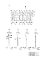
- (A) is a cross-sectional view of the lens of the objective optical system according to the first embodiment.
- (B) is a lens cross-sectional view of a flat plate at the tip and a planing negative lens.
- (A), (b), (c), (d), (e), and (f) are diagrams showing a method for manufacturing an objective optical system according to a second embodiment. It is a flowchart which shows the manufacturing method of the objective optical system which concerns on 2nd Embodiment.
- (A) is a cross-sectional view of the lens of the objective optical system of Example 1, and (b), (c), (d), and (e) are aberration diagrams.
- (A) is a cross-sectional view of the lens of the objective optical system of the second embodiment, and (b), (c), (d), and (e) are aberration diagrams.
- (A) is a cross-sectional view of the lens of the objective optical system of Example 3, and (b), (c), (d), and (e) are aberration diagrams.
- (A) is a cross-sectional view of the lens of the objective optical system of Example 4, and (b), (c), (d), and (e) are aberration diagrams. It is sectional drawing of the image pickup apparatus which concerns on 3rd Embodiment and the endoscope which concerns on 4th Embodiment.
- FIG. 1A is a cross-sectional view of the lens of the objective optical system 10 according to the first embodiment.
- the objective optical system 10 includes a flat plate SP, a plano-concave negative lens L1 with a plane facing the object side, a biconvex positive lens L2, an aperture diaphragm S, and a parallel flat plate F1 in order from the object side to the image side. It has a convex lens L3, a negative meniscus lens L4 having a convex surface facing the image side, a parallel flat plate F2, and a cover glass CG.
- the objective optical system 10 has a flat plate SP arranged on the object side most, and a plano-concave negative lens L1 having a plane facing the object side.
- the flat plate SP is a transparent material in which the flat concave negative lens L1 is also hard.
- the flat plate SP and the flat concave negative lens L1 are joined to each other.
- the following conditional expression (1) is satisfied. 10 ⁇ ⁇ 1 / t1 ⁇ 70 (1) here, ⁇ 1 is the outer diameter of the flat plate SP, t1 is the thickness of the flat plate SP, Is.
- FIG. 1B is a cross-sectional view of the lens configuration at the tip of the objective optical system 10 on the most object side.
- the flat plate SP is, for example, sapphire glass or transparent ceramics.
- Conditional formula (1) defines an appropriate ratio between the outer diameter ⁇ 1 of the flat plate SP formed of sapphire glass and the thickness t1 of the flat plate SP.
- the thickness t1 of the flat plate SP becomes large. As the thickness t1 of the flat plate SP increases, the flat plate SP becomes less likely to be deformed. When the flat plate SP is joined to the planing negative lens L1 in this state, stress tends to be concentrated on the joint surface. Further, when the thickness t1 of the flat plate SP becomes large, light rays are cast. In order to secure a wide viewing angle so that light rays are not cast, the objective optical system becomes large.
- the thickness t1 of the flat plate SP becomes thin. Therefore, the flat plate SP is easily deformed, and the mechanical strength is insufficient. If the mechanical strength of the flat plate SP is insufficient, the flat plate SP may be cracked or chipped.
- conditional expression (1') is satisfied instead of the conditional expression (1).
- the flat plate SP and the plano-concave negative lens L1 are activated bonded.
- Activated bonding means activating the material surface (bonding surface) of the substrate and directly bonding by intermolecular force. In the activated bonding, no organic adhesive (polymer adhesive, hereinafter appropriately referred to as “adhesive”) is interposed between the substrates. For this reason, “activated bonding” can increase the reliability of the bonded portion as compared with “bonding” using an adhesive.
- the configuration in which the lens and filter are adhered with an adhesive is called a cemented lens as before.
- the "activated bonding lens” and the “bonding lens using an organic adhesive” have different configurations.
- t1 is the thickness of the flat plate SP
- t2 is the thickness of the plano-concave negative lens L1 along the optical axis AX. Is.
- Conditional expression (2) defines an appropriate ratio between the thickness t1 of the flat plate SP and the thickness t2 along the optical axis AX of the planing negative lens L1.
- the thickness of the flat plate SP becomes thin.
- the flat plate SP is easily deformed. As a result, the stress at the time of activation bonding can be released. However, the mechanical strength of the surface of the flat plate SP is insufficient.
- the thickness t1 of the flat plate SP becomes large and it is difficult to be deformed. Therefore, the flat concave negative lens L1 cannot be deformed either. For this reason, material destruction such as peeling of the activated joint surface and chipping of the plano-concave negative lens L1 is likely to occur.
- conditional expression (2') is satisfied instead of the conditional expression (2).
- t1 is the thickness of the flat plate SP
- t2 is the thickness of the plano-concave negative lens L1 along the optical axis AX
- e1 is the elastic modulus of the flat plate SP
- e2 is the elastic modulus of the plano-concave negative lens L1. Is.
- Conditional expression (3) defines an appropriate division ratio of thicknesses t1 and t2 along the optical axis AX.
- the thickness t2 of the planing negative lens L1 is an uneven thickness shape in which the central portion is thin and the peripheral portion is thick. Therefore, when the planing negative lens L1 is processed and assembled, it is susceptible to bending stress.
- the elastic modulus of safaa glass is higher than that of optical glass and is hard. Therefore, the flat plate SP of sapphire glass restrains the deformation of the plano-concave negative lens L1.
- the flat plate SP of sapphire glass and the plano-concave negative lens L1 are activated and joined. Then, the stress is concentrated on the bonding interface. Therefore, it is desirable to satisfy the conditional expression (3) in order to perform a good activation bonding by reducing the stress.
- the thickness t1 of the flat plate SP of sapphire glass becomes thin.
- the flat plate SP is easily deformed.
- stress at the time of activation bonding can be released.
- the mechanical strength of the surface of the flat plate SP is insufficient.
- the thickness t1 of the flat plate SP becomes large and it is difficult to be deformed. Therefore, the flat concave negative lens L1 cannot be deformed either. For this reason, material destruction such as peeling of the activated joint surface and chipping of the plano-concave negative lens L1 is likely to occur.
- Conditional expression (4) defines an appropriate combination of the coefficient of linear expansion v1 of the flat plate SP and the coefficient of linear expansion v2 of the plano-concave negative lens L1.
- the objective optical system 10 having a wide viewing angle of 120 ° or more can be obtained.
- n2 is the refractive index of the plano-concave negative lens L1 on the d line. Is.
- the present embodiment relates to the above-mentioned method for manufacturing an objective optical system. It is necessary to achieve both design requirements such as miniaturization of the objective optical system in the radial direction at a wide angle and improvement of the mechanical strength of the lens surface. Therefore, in the present embodiment, the flat plate SP made of a thin transparent material and the plano-concave negative lens L1 formed by using a high refractive index material are integrated by activation bonding.
- the flat plate SP and the planing negative lens L1 are integrated by activation bonding. Therefore, the thickness of the flat plate SP and the plano-concave negative lens L1 can be made as thin as possible. As a result, the objective optical system manufactured according to the present embodiment has a wide viewing angle of 120 ° or more, and the radial direction of the lens can be miniaturized.
- FIG. 2 (a), (b), (c), (d), (e), and (f) are diagrams showing a method for manufacturing an objective optical system according to a second embodiment. Further, FIG. 3 is a flowchart showing a method of manufacturing the objective optical system according to the second embodiment.
- the method for manufacturing the objective optical system of the present embodiment is as follows.
- a step of providing the first substrate SP made of a transparent material (step S101 in FIG. 3) and A step of providing a second substrate LP made of optical glass constituting the planing negative lens L1 (step S102 in FIG. 3) and A step of activating and joining the first substrate SP and the second substrate LP (step S103 in FIG. 3) and
- the first substrate SP and the second substrate LP have a size corresponding to a plurality of plano-concave negative lenses L1, and a step of thinning the activated bonded first substrate SP and the second substrate LP (FIG. 3).
- the first substrate SP is a material harder than the second substrate LP.
- FIG. 2A shows, for example, sapphire glass as the first substrate SP, a first substrate SP of sapphire glass, and a second substrate LP made of optical glass constituting the plano-concave negative lens L1.
- the first substrate SP of sapphire glass uses a C-faced product (a plane perpendicular to the C-axis, which is the crystal axis).
- the light beam travels in the sapphire glass along the C axis of the sapphire glass (shown by C in FIG. 2A) at the same refractive index.
- the first substrate SP is sapphire glass.
- the hardness of the outer circumference of the crystal of the A-side product of sapphire glass is non-uniform. As a result, when the sapphire glass is centered, the outer diameter does not become a strict perfect circle, which limits the improvement of accuracy.
- A-side product of sapphire glass is used, the following problems may occur. (1) A-side products are prone to burrs (unnecessary protrusions on the machined surface) in a specific direction for centering. (2) The A-side product has birefringence that is asymmetric with respect to the optical axis. Therefore, in the wide field of view of the objective optical system, the image quality of the surroundings differs depending on the location such as the top, bottom, left, and right of the field of view.
- the birefringence becomes symmetric with respect to the optical axis AX, and the peripheral image quality becomes uniform.
- the hardness in the circumferential direction is also constant, and the outer diameter can be processed with precision.
- FIG. 2B shows a configuration in which a first substrate SP of sapphire glass and a second substrate LP made of optical glass constituting the plano-concave negative lens L1 are activated and bonded.
- first substrate SP having a size larger than the aperture of the tip planing negative lens L1 and the second substrate LP having a size larger than the aperture of the tip planing negative lens L1 are stably joined by activation bonding. Join.
- the planing negative lens L1 at the tip of the objective optical system is exposed to the surrounding environment and chemicals. Therefore, higher resistance is required. Therefore, a highly reliable joining method is required.
- the sizes of the first substrate SP and the second substrate LP are in inches. Since such substrate bonding between inch-sized sizes is performed, the bonding technique in semiconductor manufacturing, particularly the activation bonding technique described above in the first embodiment, is used in this embodiment.
- the step of activating bonding includes a step of surface activating bonding (surface activated bonding) or a step of plasma activated bonding (plasma activated bonding).
- the surfaces of the first substrate SP and the second substrate LP are subjected to chemical mechanical polishing, so-called CMP processing. It is desirable to finish with a smooth and flat surface.
- the flatness described above is not necessary for the first substrate SP of sapphire glass that can be deformed and adhered.
- the surface activation bonding energy particles such as an ion beam are used to activate and bond the surface of the first substrate SP and the surface of the second substrate LP.
- Surface activation bonding is performed under ultra-high vacuum ( 10-6 units: Pa).
- the surface-activated bonding can be a non-heated room temperature bonding.
- Plasma activated bonding can be performed under atmospheric pressure.
- the activated joint surface is irradiated with plasma in advance to lower the temperature of the joint.
- atomic diffusion bonding can also be used.
- a highly active metal thin film (Ti, AL, etc.) or a thin film made of Si is provided on the surface, and then diffusion bonding is performed under vacuum.
- FIG. 2C shows a configuration in which the activation-bonded first substrate SP and the second substrate LP are sliced.
- the first substrate SP and the second substrate LP have a size corresponding to a plurality of planing negative lenses L1. Then, the activated and bonded first substrate SP and the second substrate LP are sliced.
- the flaking is processed into individual flaked lenses A shown by the dotted line in FIG. 2C by so-called dicing or the like.
- dicing substrates that have been activated and bonded to a rectangular shape or a round shape (cylindrical shape) may be sliced by honing, laser processing, or the like.
- a lens A is subjected to a ball chipping process having a radius R by a cutting portion (not shown) to form a concave LS. Further, as shown in FIG. 2 (e), the lens A is centered and chamfered to finish the shape. Finally, as shown in FIG. 2 (f), the antireflection coating AR is applied to complete the plano-concave negative lens L1.
- a conventional method of joining after processing each small and thin part in advance is also conceivable.
- two parts having the minimum thickness along the optical axis AX are joined. Therefore, the thickness of the component along the optical axis AX after joining is doubled as compared with that before joining. Further, the thickness accuracy of the component along the optical axis after joining is the sum of the accuracy of the two components. Therefore, the thickness accuracy of the part is halved. For this reason, in the conventional method of forming individual lens elements, it becomes difficult to reduce the thickness of the lens along the optical axis AX after bonding, increase the accuracy, and improve the reliability of bonding.
- the first substrate SP and the second substrate LP are provided in advance with large outer diameters, respectively. Then, the substrates are activated and joined to be integrated. After that, the activated-bonded substrate is sliced and processed into a planing negative lens L1.
- the plano-concave negative lens L1 is manufactured by the above-mentioned process.
- the two substrates are activated and bonded in advance to form a strong (hard to crack) composite material before processing. Therefore, the thickness along the optical axis AX after joining can be processed thinner and with high accuracy. Then, since the bonding is performed on a continuous and uniform substrate surface without being affected by the edge, the bonding between the two substrates is also stable.
- sapphire glass that is so thin that the frame cannot be assembled can be activated and bonded with the size of the plano-concave negative lens L1 alone. Then, the activated-bonded substrate is thinly processed. Therefore, the plano-concave negative lens L1 can be formed so thin that it cannot be processed by the lens alone.
- FIG. 8 is a cross-sectional view of the image pickup apparatus according to the third embodiment and the endoscope according to the fourth embodiment.
- FIG. 8 is a diagram showing an image pickup apparatus 20 according to a third embodiment.
- the image pickup device 20 Objective optical system OBL and It has an image sensor IMG and
- the objective optical system OBL is the above-mentioned objective optical system 10.
- the imaging device 20 of this embodiment has the above-mentioned objective optical system 10. Therefore, the image pickup apparatus 20 of the present embodiment has a wide viewing angle, a small outer diameter, and the lens surface at the tip is reinforced against scratches and chips.
- FIG. 8 is also a diagram showing the endoscope 30 according to the fourth embodiment.
- the endoscope 30 Objective optical system OBL and It has an image sensor IMG and
- the objective optical system OBL is the above-mentioned objective optical system 10.
- the endoscope 30 of this embodiment has the above-mentioned objective optical system 10. Therefore, the endoscope 30 of the present embodiment has a wide viewing angle, a small outer diameter, and the lens surface at the tip is reinforced against scratches and chips.
- FIG. 4A is a cross-sectional view of the lens of the objective optical system 10 of the first embodiment.
- the objective optical system is a flat plate SP (sapphire glass), a plano-concave negative lens L1 with a plane facing the object side, a biconvex positive lens L2, and an aperture aperture S in order from the object side to the image side.
- the parallel flat plate F1 is an infrared cut filter.
- I is an imaging surface.
- the flat plate SP and the planing negative lens L1 are activated and joined.
- the biconvex positive lens L3 and the negative meniscus lens L4 are joined.
- the parallel flat plate F2 and the cover glass CG are joined.
- FIG. 5A is a cross-sectional view of the lens of the objective optical system 11 of the second embodiment.
- the objective optical system is a flat plate SP (sapphire glass), a plano-concave negative lens L1 with a plane facing the object side, a biconvex positive lens L2, and an aperture aperture S in order from the object side to the image side.
- the parallel flat plate F1 is an infrared cut filter.
- I is an imaging surface.
- the flat plate SP and the planing negative lens L1 are activated and joined.
- the biconvex positive lens L3 and the negative meniscus lens L4 are joined.
- the parallel flat plate F2 and the cover glass CG are joined.
- FIG. 6A is a cross-sectional view of the lens of the objective optical system 12 of the third embodiment.
- the objective optical system is a flat plate SP (sapphire glass), a plano-concave negative lens L1 with a flat surface facing the object side, a parallel flat plate F1, and a biconcave negative lens L2 in order from the object side to the image side.
- Negative lens L6 plano-convex positive lens L7 with a flat surface facing the object side
- biconvex positive lens L8 negative meniscus lens L9 with a convex surface facing the image side
- parallel flat plates F2, F3, F4, F5, F6 And a cover glass CG.
- the parallel flat plate F1 is an infrared cut filter.
- I is an imaging surface.
- the flat plate SP and the planing negative lens L1 are activated and joined. Both concave negative lenses L2 and plano-convex positive lenses L3 are joined.
- the biconvex positive lens L5, the plano-concave negative lens L6, and the plano-convex positive lens L7 are joined.
- the biconvex positive lens L8 and the negative meniscus lens L9 are joined. It is joined to the parallel flat plates F2 and F3.
- the parallel flat plates F4, F5, F6 and the cover glass CG are joined.
- SA spherical aberration
- AS astigmatism
- DT distortion
- CC chromatic aberration of magnification
- FIG. 7A is a cross-sectional view of the lens of the objective optical system 13 of the fourth embodiment.
- the objective optical system is a flat plate SP (sapphire glass), a plano-concave negative lens L1 with a flat surface facing the object side, a parallel flat plate F1, and a biconcave negative lens L2 in order from the object side to the image side.
- Negative lens L6 plano-convex positive lens L7 with a flat surface facing the object side
- biconvex positive lens L8 negative meniscus lens L9 with a convex surface facing the image side
- parallel flat plates F2, F3, F4, F5, F6 And a cover glass CG.
- the parallel flat plate F1 is an infrared cut filter.
- I is an imaging surface.
- the flat plate SP and the planing negative lens L1 are activated and joined. Both concave negative lenses L2 and plano-convex positive lenses L3 are joined.
- the biconvex positive lens L5, the plano-concave negative lens L6, and the plano-convex positive lens L7 are joined.
- the biconvex regular lens L8 and the biconvex regular lens L9 are joined. It is joined to the parallel flat plates F2 and F3.
- the parallel flat plates F4, F5, F6 and the cover glass CG are joined.
- r is the radius of curvature of each lens surface
- d is the distance between each lens surface
- the aperture is an aperture diaphragm
- nd is the refractive index of the d-line of each lens
- ⁇ d is the Abbe number of each lens.
- d1 of the distance d between the lens surfaces corresponds to t1.
- d2 corresponds to t2.
- the unit of the interval, the length, and the thickness in various data is mm.
- Example 1 Example 2
- Example 3 Example 4 (1) ⁇ 1 / t1 70 12.173 68 17 (2) t1 / t2 0.111 1.352 0.166 1.333 (3) (t1 / t2) ⁇ (e1 / e2) 0.411 5 0.617 4.934 (4)
- the above-mentioned objective optical system may satisfy a plurality of configurations at the same time. This is preferable in order to obtain a good objective optical system. Moreover, the combination of preferable configurations is arbitrary. Further, for each conditional expression, only the upper limit value or the lower limit value of the numerical range of the more limited conditional expression may be limited.
- the bonding between the flat plate SP and the planing negative lens L1 is not limited to the activation bonding described above.
- the flat plate SP is a transparent material having a Vickers hardness of 14 GPa or more. Further, the flat plate SP is preferably sapphire glass or transparent ceramics.
- the flat plate SP is not limited to sapphire, and may be a material harder than the planing negative lens L1.
- the Vickers hardness may be the above glass 14 GPa, monocrystalline or polycrystalline, such as YAG and YSZ, alumina, Si 3 Vickers hardness such as N 4, may be like more transparent ceramic 14 GPa.
- An example of the Vickers hardness of the material used for the flat plate SP is shown below. Material Vickers hardness [GPa] Sapphire 22.5 YAG polycrystal 15 YSZ single crystal 19.5 Alumina 15.2 Si 3 N 4 14
- the present invention has a wide viewing angle, a small outer diameter, and an objective optical system, an imaging device, an endoscope, and an objective optical system that are reinforced against scratches and chips on the lens surface at the tip. Suitable for the manufacturing method of.
Landscapes
- Physics & Mathematics (AREA)
- Optics & Photonics (AREA)
- Health & Medical Sciences (AREA)
- Life Sciences & Earth Sciences (AREA)
- General Physics & Mathematics (AREA)
- Surgery (AREA)
- Astronomy & Astrophysics (AREA)
- Biomedical Technology (AREA)
- Animal Behavior & Ethology (AREA)
- Engineering & Computer Science (AREA)
- Pathology (AREA)
- Heart & Thoracic Surgery (AREA)
- Medical Informatics (AREA)
- Molecular Biology (AREA)
- Radiology & Medical Imaging (AREA)
- General Health & Medical Sciences (AREA)
- Public Health (AREA)
- Veterinary Medicine (AREA)
- Nuclear Medicine, Radiotherapy & Molecular Imaging (AREA)
- Biophysics (AREA)
- Lenses (AREA)
Priority Applications (3)
| Application Number | Priority Date | Filing Date | Title |
|---|---|---|---|
| JP2021555629A JPWO2021095090A1 (https=) | 2019-11-11 | 2019-11-11 | |
| PCT/JP2019/044107 WO2021095090A1 (ja) | 2019-11-11 | 2019-11-11 | 対物光学系、撮像装置、内視鏡及び対物光学系の製造方法 |
| US17/704,067 US12306394B2 (en) | 2019-11-11 | 2022-03-25 | Objective optical system, method of manufacturing objective optical system image pickup apparatus, and endoscope |
Applications Claiming Priority (1)
| Application Number | Priority Date | Filing Date | Title |
|---|---|---|---|
| PCT/JP2019/044107 WO2021095090A1 (ja) | 2019-11-11 | 2019-11-11 | 対物光学系、撮像装置、内視鏡及び対物光学系の製造方法 |
Related Child Applications (1)
| Application Number | Title | Priority Date | Filing Date |
|---|---|---|---|
| US17/704,067 Continuation US12306394B2 (en) | 2019-11-11 | 2022-03-25 | Objective optical system, method of manufacturing objective optical system image pickup apparatus, and endoscope |
Publications (1)
| Publication Number | Publication Date |
|---|---|
| WO2021095090A1 true WO2021095090A1 (ja) | 2021-05-20 |
Family
ID=75911881
Family Applications (1)
| Application Number | Title | Priority Date | Filing Date |
|---|---|---|---|
| PCT/JP2019/044107 Ceased WO2021095090A1 (ja) | 2019-11-11 | 2019-11-11 | 対物光学系、撮像装置、内視鏡及び対物光学系の製造方法 |
Country Status (3)
| Country | Link |
|---|---|
| US (1) | US12306394B2 (https=) |
| JP (1) | JPWO2021095090A1 (https=) |
| WO (1) | WO2021095090A1 (https=) |
Cited By (1)
| Publication number | Priority date | Publication date | Assignee | Title |
|---|---|---|---|---|
| WO2024070644A1 (ja) * | 2022-09-27 | 2024-04-04 | コニカミノルタ株式会社 | 赤外線レンズ、赤外線光学系及び赤外線撮像装置 |
Citations (3)
| Publication number | Priority date | Publication date | Assignee | Title |
|---|---|---|---|---|
| WO2001018585A1 (en) * | 1999-09-08 | 2001-03-15 | Olympus Optical Co., Ltd. | Image pickup optical system for endoscope |
| WO2017038961A1 (ja) * | 2015-09-03 | 2017-03-09 | 丸文株式会社 | 深紫外led及びその製造方法 |
| WO2019180979A1 (ja) * | 2018-03-23 | 2019-09-26 | 日本碍子株式会社 | 電気光学素子のための複合基板 |
Family Cites Families (8)
| Publication number | Priority date | Publication date | Assignee | Title |
|---|---|---|---|---|
| JPH10123411A (ja) * | 1996-10-24 | 1998-05-15 | Olympus Optical Co Ltd | ファイバースコープ光学系 |
| JP2002365535A (ja) | 2001-06-08 | 2002-12-18 | Olympus Optical Co Ltd | 内視鏡対物レンズ |
| JP2004107602A (ja) * | 2002-09-20 | 2004-04-08 | Olympus Corp | 光学素子の接着剤組成物及び接着構造体 |
| JP2011022444A (ja) * | 2009-07-17 | 2011-02-03 | Panasonic Corp | 接合光学素子 |
| EP2648026B1 (en) * | 2011-06-23 | 2017-09-27 | Olympus Corporation | Endoscope objective optical system |
| JP2017187663A (ja) * | 2016-04-07 | 2017-10-12 | キヤノン株式会社 | 結像光学系 |
| JP2018182172A (ja) * | 2017-04-18 | 2018-11-15 | 日本電信電話株式会社 | 受光素子およびその作製方法 |
| DE102017113273A1 (de) | 2017-06-16 | 2018-12-20 | avateramedical GmBH | Objektiv für ein Endoskop und Endoskop |
-
2019
- 2019-11-11 WO PCT/JP2019/044107 patent/WO2021095090A1/ja not_active Ceased
- 2019-11-11 JP JP2021555629A patent/JPWO2021095090A1/ja active Pending
-
2022
- 2022-03-25 US US17/704,067 patent/US12306394B2/en active Active
Patent Citations (3)
| Publication number | Priority date | Publication date | Assignee | Title |
|---|---|---|---|---|
| WO2001018585A1 (en) * | 1999-09-08 | 2001-03-15 | Olympus Optical Co., Ltd. | Image pickup optical system for endoscope |
| WO2017038961A1 (ja) * | 2015-09-03 | 2017-03-09 | 丸文株式会社 | 深紫外led及びその製造方法 |
| WO2019180979A1 (ja) * | 2018-03-23 | 2019-09-26 | 日本碍子株式会社 | 電気光学素子のための複合基板 |
Cited By (1)
| Publication number | Priority date | Publication date | Assignee | Title |
|---|---|---|---|---|
| WO2024070644A1 (ja) * | 2022-09-27 | 2024-04-04 | コニカミノルタ株式会社 | 赤外線レンズ、赤外線光学系及び赤外線撮像装置 |
Also Published As
| Publication number | Publication date |
|---|---|
| JPWO2021095090A1 (https=) | 2021-05-20 |
| US20220214534A1 (en) | 2022-07-07 |
| US12306394B2 (en) | 2025-05-20 |
Similar Documents
| Publication | Publication Date | Title |
|---|---|---|
| JP6081683B1 (ja) | 内視鏡用対物光学系 | |
| JP6134756B2 (ja) | 撮像レンズおよびそれを備えた電子機器 | |
| JP3051035B2 (ja) | 内視鏡用対物レンズ | |
| CN104808317B (zh) | 光学成像镜头及应用该光学成像镜头的电子装置 | |
| CN103282817B (zh) | 内窥镜用物镜光学系统 | |
| TW201348735A (zh) | 影像擷取系統透鏡組及取像裝置 | |
| US12140747B2 (en) | Lens system for a video endoscope, endoscope objective, video endoscope, and assembly method | |
| CN109633869B (zh) | 光学镜头、取像装置及电子装置 | |
| TW201727303A (zh) | 光學影像鏡組、取像裝置及電子裝置 | |
| US10809523B2 (en) | Endoscope objective optical system | |
| JPH10170821A (ja) | 内視鏡対物レンズ | |
| TW201732358A (zh) | 光學成像鏡頭 | |
| JP6416451B1 (ja) | 内視鏡用対物光学系 | |
| US12306394B2 (en) | Objective optical system, method of manufacturing objective optical system image pickup apparatus, and endoscope | |
| US10884223B2 (en) | Objective optical system for endoscope | |
| JP6720026B2 (ja) | 内視鏡用対物光学系 | |
| JP2003140037A (ja) | 貼合レンズ | |
| JPH08334688A (ja) | 内視鏡用対物レンズ | |
| TWI890166B (zh) | 光學成像鏡頭 | |
| JPWO2021095090A5 (https=) | ||
| JP2000187155A (ja) | 内視鏡対物光学系 | |
| JPH11271607A (ja) | 小型撮像光学系 | |
| JP2011099963A (ja) | 高被写界深度マイクロ単レンズ | |
| JP2004264835A (ja) | 内視鏡用対物レンズ | |
| CN115343830B (zh) | 一种平场远心扫描镜头 |
Legal Events
| Date | Code | Title | Description |
|---|---|---|---|
| 121 | Ep: the epo has been informed by wipo that ep was designated in this application |
Ref document number: 19952303 Country of ref document: EP Kind code of ref document: A1 |
|
| ENP | Entry into the national phase |
Ref document number: 2021555629 Country of ref document: JP Kind code of ref document: A |
|
| NENP | Non-entry into the national phase |
Ref country code: DE |
|
| 122 | Ep: pct application non-entry in european phase |
Ref document number: 19952303 Country of ref document: EP Kind code of ref document: A1 |