WO2021079937A1 - Dispositif de stockage électrique - Google Patents
Dispositif de stockage électrique Download PDFInfo
- Publication number
- WO2021079937A1 WO2021079937A1 PCT/JP2020/039730 JP2020039730W WO2021079937A1 WO 2021079937 A1 WO2021079937 A1 WO 2021079937A1 JP 2020039730 W JP2020039730 W JP 2020039730W WO 2021079937 A1 WO2021079937 A1 WO 2021079937A1
- Authority
- WO
- WIPO (PCT)
- Prior art keywords
- power storage
- detection line
- storage elements
- holding
- bus bar
- Prior art date
Links
- 238000001514 detection method Methods 0.000 claims description 185
- 238000005192 partition Methods 0.000 description 15
- 239000000758 substrate Substances 0.000 description 14
- 230000005611 electricity Effects 0.000 description 8
- 229910052751 metal Inorganic materials 0.000 description 6
- 239000002184 metal Substances 0.000 description 6
- 239000011347 resin Substances 0.000 description 6
- 229920005989 resin Polymers 0.000 description 6
- 239000004743 Polypropylene Substances 0.000 description 5
- 229920001155 polypropylene Polymers 0.000 description 5
- 230000001154 acute effect Effects 0.000 description 4
- 230000004888 barrier function Effects 0.000 description 4
- 238000007599 discharging Methods 0.000 description 4
- 230000004048 modification Effects 0.000 description 4
- 238000012986 modification Methods 0.000 description 4
- 239000011255 nonaqueous electrolyte Substances 0.000 description 4
- 239000004698 Polyethylene Substances 0.000 description 3
- 210000000078 claw Anatomy 0.000 description 3
- 238000010586 diagram Methods 0.000 description 3
- 238000009434 installation Methods 0.000 description 3
- 239000000463 material Substances 0.000 description 3
- 230000000149 penetrating effect Effects 0.000 description 3
- 229920000573 polyethylene Polymers 0.000 description 3
- 229910000838 Al alloy Inorganic materials 0.000 description 2
- XEEYBQQBJWHFJM-UHFFFAOYSA-N Iron Chemical compound [Fe] XEEYBQQBJWHFJM-UHFFFAOYSA-N 0.000 description 2
- HBBGRARXTFLTSG-UHFFFAOYSA-N Lithium ion Chemical compound [Li+] HBBGRARXTFLTSG-UHFFFAOYSA-N 0.000 description 2
- 239000004734 Polyphenylene sulfide Substances 0.000 description 2
- 229910052782 aluminium Inorganic materials 0.000 description 2
- XAGFODPZIPBFFR-UHFFFAOYSA-N aluminium Chemical compound [Al] XAGFODPZIPBFFR-UHFFFAOYSA-N 0.000 description 2
- 230000033228 biological regulation Effects 0.000 description 2
- 238000004891 communication Methods 0.000 description 2
- 239000008151 electrolyte solution Substances 0.000 description 2
- 238000007667 floating Methods 0.000 description 2
- 229910001416 lithium ion Inorganic materials 0.000 description 2
- 229920000515 polycarbonate Polymers 0.000 description 2
- 239000004417 polycarbonate Substances 0.000 description 2
- 229920000069 polyphenylene sulfide Polymers 0.000 description 2
- -1 polypropylene Polymers 0.000 description 2
- 125000006850 spacer group Chemical group 0.000 description 2
- 239000010935 stainless steel Substances 0.000 description 2
- 229910001220 stainless steel Inorganic materials 0.000 description 2
- 230000008719 thickening Effects 0.000 description 2
- RYGMFSIKBFXOCR-UHFFFAOYSA-N Copper Chemical compound [Cu] RYGMFSIKBFXOCR-UHFFFAOYSA-N 0.000 description 1
- 229910000881 Cu alloy Inorganic materials 0.000 description 1
- 229910001335 Galvanized steel Inorganic materials 0.000 description 1
- 238000005452 bending Methods 0.000 description 1
- 239000003990 capacitor Substances 0.000 description 1
- 238000010276 construction Methods 0.000 description 1
- 230000001276 controlling effect Effects 0.000 description 1
- 239000010949 copper Substances 0.000 description 1
- 229910052802 copper Inorganic materials 0.000 description 1
- 238000006073 displacement reaction Methods 0.000 description 1
- 230000000694 effects Effects 0.000 description 1
- 239000008397 galvanized steel Substances 0.000 description 1
- 230000017525 heat dissipation Effects 0.000 description 1
- 238000002347 injection Methods 0.000 description 1
- 239000007924 injection Substances 0.000 description 1
- 230000002452 interceptive effect Effects 0.000 description 1
- 229910052742 iron Inorganic materials 0.000 description 1
- 239000007788 liquid Substances 0.000 description 1
- 238000012544 monitoring process Methods 0.000 description 1
- 238000010248 power generation Methods 0.000 description 1
- 230000001105 regulatory effect Effects 0.000 description 1
- 230000003014 reinforcing effect Effects 0.000 description 1
- 239000007784 solid electrolyte Substances 0.000 description 1
Images


Classifications
-
- H—ELECTRICITY
- H01—ELECTRIC ELEMENTS
- H01G—CAPACITORS; CAPACITORS, RECTIFIERS, DETECTORS, SWITCHING DEVICES OR LIGHT-SENSITIVE DEVICES, OF THE ELECTROLYTIC TYPE
- H01G11/00—Hybrid capacitors, i.e. capacitors having different positive and negative electrodes; Electric double-layer [EDL] capacitors; Processes for the manufacture thereof or of parts thereof
- H01G11/14—Arrangements or processes for adjusting or protecting hybrid or EDL capacitors
- H01G11/18—Arrangements or processes for adjusting or protecting hybrid or EDL capacitors against thermal overloads, e.g. heating, cooling or ventilating
-
- H—ELECTRICITY
- H01—ELECTRIC ELEMENTS
- H01M—PROCESSES OR MEANS, e.g. BATTERIES, FOR THE DIRECT CONVERSION OF CHEMICAL ENERGY INTO ELECTRICAL ENERGY
- H01M50/00—Constructional details or processes of manufacture of the non-active parts of electrochemical cells other than fuel cells, e.g. hybrid cells
- H01M50/30—Arrangements for facilitating escape of gases
- H01M50/35—Gas exhaust passages comprising elongated, tortuous or labyrinth-shaped exhaust passages
- H01M50/358—External gas exhaust passages located on the battery cover or case
-
- H—ELECTRICITY
- H01—ELECTRIC ELEMENTS
- H01G—CAPACITORS; CAPACITORS, RECTIFIERS, DETECTORS, SWITCHING DEVICES OR LIGHT-SENSITIVE DEVICES, OF THE ELECTROLYTIC TYPE
- H01G11/00—Hybrid capacitors, i.e. capacitors having different positive and negative electrodes; Electric double-layer [EDL] capacitors; Processes for the manufacture thereof or of parts thereof
- H01G11/08—Structural combinations, e.g. assembly or connection, of hybrid or EDL capacitors with other electric components, at least one hybrid or EDL capacitor being the main component
-
- H—ELECTRICITY
- H01—ELECTRIC ELEMENTS
- H01G—CAPACITORS; CAPACITORS, RECTIFIERS, DETECTORS, SWITCHING DEVICES OR LIGHT-SENSITIVE DEVICES, OF THE ELECTROLYTIC TYPE
- H01G11/00—Hybrid capacitors, i.e. capacitors having different positive and negative electrodes; Electric double-layer [EDL] capacitors; Processes for the manufacture thereof or of parts thereof
- H01G11/10—Multiple hybrid or EDL capacitors, e.g. arrays or modules
-
- H—ELECTRICITY
- H01—ELECTRIC ELEMENTS
- H01G—CAPACITORS; CAPACITORS, RECTIFIERS, DETECTORS, SWITCHING DEVICES OR LIGHT-SENSITIVE DEVICES, OF THE ELECTROLYTIC TYPE
- H01G11/00—Hybrid capacitors, i.e. capacitors having different positive and negative electrodes; Electric double-layer [EDL] capacitors; Processes for the manufacture thereof or of parts thereof
- H01G11/74—Terminals, e.g. extensions of current collectors
- H01G11/76—Terminals, e.g. extensions of current collectors specially adapted for integration in multiple or stacked hybrid or EDL capacitors
-
- H—ELECTRICITY
- H01—ELECTRIC ELEMENTS
- H01G—CAPACITORS; CAPACITORS, RECTIFIERS, DETECTORS, SWITCHING DEVICES OR LIGHT-SENSITIVE DEVICES, OF THE ELECTROLYTIC TYPE
- H01G11/00—Hybrid capacitors, i.e. capacitors having different positive and negative electrodes; Electric double-layer [EDL] capacitors; Processes for the manufacture thereof or of parts thereof
- H01G11/78—Cases; Housings; Encapsulations; Mountings
- H01G11/82—Fixing or assembling a capacitive element in a housing, e.g. mounting electrodes, current collectors or terminals in containers or encapsulations
-
- H—ELECTRICITY
- H01—ELECTRIC ELEMENTS
- H01G—CAPACITORS; CAPACITORS, RECTIFIERS, DETECTORS, SWITCHING DEVICES OR LIGHT-SENSITIVE DEVICES, OF THE ELECTROLYTIC TYPE
- H01G2/00—Details of capacitors not covered by a single one of groups H01G4/00-H01G11/00
- H01G2/02—Mountings
-
- H—ELECTRICITY
- H01—ELECTRIC ELEMENTS
- H01M—PROCESSES OR MEANS, e.g. BATTERIES, FOR THE DIRECT CONVERSION OF CHEMICAL ENERGY INTO ELECTRICAL ENERGY
- H01M10/00—Secondary cells; Manufacture thereof
- H01M10/42—Methods or arrangements for servicing or maintenance of secondary cells or secondary half-cells
- H01M10/48—Accumulators combined with arrangements for measuring, testing or indicating the condition of cells, e.g. the level or density of the electrolyte
- H01M10/482—Accumulators combined with arrangements for measuring, testing or indicating the condition of cells, e.g. the level or density of the electrolyte for several batteries or cells simultaneously or sequentially
-
- H—ELECTRICITY
- H01—ELECTRIC ELEMENTS
- H01M—PROCESSES OR MEANS, e.g. BATTERIES, FOR THE DIRECT CONVERSION OF CHEMICAL ENERGY INTO ELECTRICAL ENERGY
- H01M50/00—Constructional details or processes of manufacture of the non-active parts of electrochemical cells other than fuel cells, e.g. hybrid cells
- H01M50/20—Mountings; Secondary casings or frames; Racks, modules or packs; Suspension devices; Shock absorbers; Transport or carrying devices; Holders
- H01M50/204—Racks, modules or packs for multiple batteries or multiple cells
- H01M50/207—Racks, modules or packs for multiple batteries or multiple cells characterised by their shape
- H01M50/209—Racks, modules or packs for multiple batteries or multiple cells characterised by their shape adapted for prismatic or rectangular cells
-
- H—ELECTRICITY
- H01—ELECTRIC ELEMENTS
- H01M—PROCESSES OR MEANS, e.g. BATTERIES, FOR THE DIRECT CONVERSION OF CHEMICAL ENERGY INTO ELECTRICAL ENERGY
- H01M50/00—Constructional details or processes of manufacture of the non-active parts of electrochemical cells other than fuel cells, e.g. hybrid cells
- H01M50/20—Mountings; Secondary casings or frames; Racks, modules or packs; Suspension devices; Shock absorbers; Transport or carrying devices; Holders
- H01M50/262—Mountings; Secondary casings or frames; Racks, modules or packs; Suspension devices; Shock absorbers; Transport or carrying devices; Holders with fastening means, e.g. locks
-
- H—ELECTRICITY
- H01—ELECTRIC ELEMENTS
- H01M—PROCESSES OR MEANS, e.g. BATTERIES, FOR THE DIRECT CONVERSION OF CHEMICAL ENERGY INTO ELECTRICAL ENERGY
- H01M50/00—Constructional details or processes of manufacture of the non-active parts of electrochemical cells other than fuel cells, e.g. hybrid cells
- H01M50/20—Mountings; Secondary casings or frames; Racks, modules or packs; Suspension devices; Shock absorbers; Transport or carrying devices; Holders
- H01M50/298—Mountings; Secondary casings or frames; Racks, modules or packs; Suspension devices; Shock absorbers; Transport or carrying devices; Holders characterised by the wiring of battery packs
-
- H—ELECTRICITY
- H01—ELECTRIC ELEMENTS
- H01M—PROCESSES OR MEANS, e.g. BATTERIES, FOR THE DIRECT CONVERSION OF CHEMICAL ENERGY INTO ELECTRICAL ENERGY
- H01M50/00—Constructional details or processes of manufacture of the non-active parts of electrochemical cells other than fuel cells, e.g. hybrid cells
- H01M50/30—Arrangements for facilitating escape of gases
- H01M50/342—Non-re-sealable arrangements
- H01M50/3425—Non-re-sealable arrangements in the form of rupturable membranes or weakened parts, e.g. pierced with the aid of a sharp member
-
- H—ELECTRICITY
- H01—ELECTRIC ELEMENTS
- H01M—PROCESSES OR MEANS, e.g. BATTERIES, FOR THE DIRECT CONVERSION OF CHEMICAL ENERGY INTO ELECTRICAL ENERGY
- H01M50/00—Constructional details or processes of manufacture of the non-active parts of electrochemical cells other than fuel cells, e.g. hybrid cells
- H01M50/50—Current conducting connections for cells or batteries
- H01M50/502—Interconnectors for connecting terminals of adjacent batteries; Interconnectors for connecting cells outside a battery casing
- H01M50/507—Interconnectors for connecting terminals of adjacent batteries; Interconnectors for connecting cells outside a battery casing comprising an arrangement of two or more busbars within a container structure, e.g. busbar modules
-
- H—ELECTRICITY
- H01—ELECTRIC ELEMENTS
- H01G—CAPACITORS; CAPACITORS, RECTIFIERS, DETECTORS, SWITCHING DEVICES OR LIGHT-SENSITIVE DEVICES, OF THE ELECTROLYTIC TYPE
- H01G11/00—Hybrid capacitors, i.e. capacitors having different positive and negative electrodes; Electric double-layer [EDL] capacitors; Processes for the manufacture thereof or of parts thereof
- H01G11/10—Multiple hybrid or EDL capacitors, e.g. arrays or modules
- H01G11/12—Stacked hybrid or EDL capacitors
-
- H—ELECTRICITY
- H01—ELECTRIC ELEMENTS
- H01G—CAPACITORS; CAPACITORS, RECTIFIERS, DETECTORS, SWITCHING DEVICES OR LIGHT-SENSITIVE DEVICES, OF THE ELECTROLYTIC TYPE
- H01G11/00—Hybrid capacitors, i.e. capacitors having different positive and negative electrodes; Electric double-layer [EDL] capacitors; Processes for the manufacture thereof or of parts thereof
- H01G11/14—Arrangements or processes for adjusting or protecting hybrid or EDL capacitors
-
- H—ELECTRICITY
- H01—ELECTRIC ELEMENTS
- H01G—CAPACITORS; CAPACITORS, RECTIFIERS, DETECTORS, SWITCHING DEVICES OR LIGHT-SENSITIVE DEVICES, OF THE ELECTROLYTIC TYPE
- H01G11/00—Hybrid capacitors, i.e. capacitors having different positive and negative electrodes; Electric double-layer [EDL] capacitors; Processes for the manufacture thereof or of parts thereof
- H01G11/78—Cases; Housings; Encapsulations; Mountings
-
- H—ELECTRICITY
- H01—ELECTRIC ELEMENTS
- H01M—PROCESSES OR MEANS, e.g. BATTERIES, FOR THE DIRECT CONVERSION OF CHEMICAL ENERGY INTO ELECTRICAL ENERGY
- H01M50/00—Constructional details or processes of manufacture of the non-active parts of electrochemical cells other than fuel cells, e.g. hybrid cells
- H01M50/50—Current conducting connections for cells or batteries
- H01M50/569—Constructional details of current conducting connections for detecting conditions inside cells or batteries, e.g. details of voltage sensing terminals
-
- Y—GENERAL TAGGING OF NEW TECHNOLOGICAL DEVELOPMENTS; GENERAL TAGGING OF CROSS-SECTIONAL TECHNOLOGIES SPANNING OVER SEVERAL SECTIONS OF THE IPC; TECHNICAL SUBJECTS COVERED BY FORMER USPC CROSS-REFERENCE ART COLLECTIONS [XRACs] AND DIGESTS
- Y02—TECHNOLOGIES OR APPLICATIONS FOR MITIGATION OR ADAPTATION AGAINST CLIMATE CHANGE
- Y02E—REDUCTION OF GREENHOUSE GAS [GHG] EMISSIONS, RELATED TO ENERGY GENERATION, TRANSMISSION OR DISTRIBUTION
- Y02E60/00—Enabling technologies; Technologies with a potential or indirect contribution to GHG emissions mitigation
- Y02E60/10—Energy storage using batteries
-
- Y—GENERAL TAGGING OF NEW TECHNOLOGICAL DEVELOPMENTS; GENERAL TAGGING OF CROSS-SECTIONAL TECHNOLOGIES SPANNING OVER SEVERAL SECTIONS OF THE IPC; TECHNICAL SUBJECTS COVERED BY FORMER USPC CROSS-REFERENCE ART COLLECTIONS [XRACs] AND DIGESTS
- Y02—TECHNOLOGIES OR APPLICATIONS FOR MITIGATION OR ADAPTATION AGAINST CLIMATE CHANGE
- Y02T—CLIMATE CHANGE MITIGATION TECHNOLOGIES RELATED TO TRANSPORTATION
- Y02T10/00—Road transport of goods or passengers
- Y02T10/60—Other road transportation technologies with climate change mitigation effect
- Y02T10/70—Energy storage systems for electromobility, e.g. batteries
Definitions
- the present invention relates to a power storage device.
- bus bar 16 for connecting electrode terminals provided in each power storage element is held by a bus bar holding member (bus bar holder 6) (see Patent Document 1). ).
- the bus bar holding member on one side in the cell width direction and the bus bar holding member on the other side may be connected by a plurality of connecting portions (ribs 39).
- a gas path may be provided on the gas discharge valve of each power storage element.
- the high temperature gas passing through the path exposes a plurality of connecting portions, which may melt or burn.
- An object of the present invention is to suppress the influence of gas on the inside of the power storage device while improving the space efficiency in the power storage device.
- the power storage device has a gas discharge valve, and is electrically connected to a plurality of power storage elements in which the gas discharge valves are arranged in the same direction and a plurality of power storage elements.
- a plurality of bus bars and a bus bar holding member arranged on a plurality of power storage elements to hold the plurality of bus bars are provided, and the power storage elements are arranged on a main body having a gas discharge valve on the upper surface and an upper surface of the main body.
- the bus bar holding member is provided with a pair of electrode terminals, a first holding portion arranged on one side of a gas discharge valve on a plurality of power storage elements, and a gas discharge on the plurality of power storage elements.
- a second holding portion arranged on the other side of the valve and a connecting portion arranged between at least a pair of adjacent storage elements among the plurality of power storage elements and connecting the first holding part and the second holding part.
- the upper end surface of a part of the connecting portion is arranged below the upper surface of the main body portion or flush with the upper surface of the main body portion.
- the influence of gas on the power storage device can be suppressed while improving the space efficiency in the power storage device.
- FIG. 1 is a perspective view showing the appearance of the power storage device according to the embodiment.
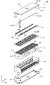
- FIG. 2 is an exploded perspective view showing each component when the power storage unit according to the embodiment is disassembled.
- FIG. 3 is an exploded perspective view showing a schematic configuration of an exhaust unit and a bus bar frame according to an embodiment.
- FIG. 4 is a top view showing a schematic configuration of the bus bar frame according to the embodiment.
- FIG. 5 is an explanatory diagram showing a positional relationship between the connecting portion and the power storage element according to the embodiment.
- FIG. 6 is a cross-sectional view showing the positional relationship between the connecting portion and the exhaust portion according to the embodiment.
- FIG. 7 is a top view showing a schematic configuration of the guide portion according to the embodiment.
- FIG. 8 is a perspective view showing a schematic configuration of the detection line holding portion according to the embodiment.
- FIG. 9 is a cross-sectional view showing a schematic configuration of the detection line holding portion according to the embodiment.
- FIG. 10 is a cross-sectional view showing a schematic configuration of the detection line holding portion according to the first modification.
- FIG. 11 is a perspective view showing the vicinity of the guide portion in the bus bar frame according to the modified example 2.
- a gas path may be provided on the gas discharge valve of each power storage element.
- the high temperature gas passing through the path exposes a plurality of connecting portions, which may melt or burn.
- An object of the present invention is to suppress the influence of gas on the inside of the power storage device while improving the space efficiency in the power storage device.
- the power storage device has a gas discharge valve, and is electrically connected to a plurality of power storage elements in which the gas discharge valves are arranged in the same direction and a plurality of power storage elements.
- a plurality of bus bars and a bus bar holding member arranged on a plurality of power storage elements to hold the plurality of bus bars are provided, and the power storage elements are arranged on a main body having a gas discharge valve on the upper surface and an upper surface of the main body.
- the bus bar holding member is provided with a pair of electrode terminals, a first holding portion arranged on one side of a gas discharge valve on a plurality of power storage elements, and a gas discharge on the plurality of power storage elements.
- a second holding portion arranged on the other side of the valve and a connecting portion arranged between at least a pair of adjacent storage elements among the plurality of power storage elements and connecting the first holding part and the second holding part.
- the upper end surface of a part of the connecting portion is arranged below the upper surface of the main body portion or flush with the upper surface of the main body portion.
- the connecting portion is arranged between at least a pair of adjacent power storage elements, the gas discharge valve of each power storage element is exposed. Therefore, it is possible to suppress the influence of the gas discharged from the gas discharge valve on the connecting portion. Since the upper end surface of a part of the connecting portion is arranged below or flush with the upper surface of the main body portion of the power storage element, a space directly above the portion can be secured. Therefore, the space efficiency in the power storage device can be improved. As a result, it is possible to suppress the influence of gas on the connecting portion while improving the space efficiency in the power storage device.
- the connecting portion may be arranged between each of a plurality of adjacent pairs of power storage elements.
- the connecting portion is arranged between each of the plurality of pairs of power storage elements adjacent to each other, the first holding portion and the second holding portion are connected by the plurality of connecting portions.
- the rigidity of the bus bar holding member can be increased. Since the upper end surface of a part of each connecting portion is located below or flush with the upper surface of the main body portion of the power storage element, it is possible to secure a space directly above the portion at each connecting portion. Therefore, the space efficiency in the power storage device can be further improved.
- the power storage device may be provided with an exhaust member that is arranged on the connecting portion of the bus bar holding member and forms an exhaust path for the gas discharged from the gas discharge valve.
- the exhaust member since the exhaust member is arranged on the connecting portion, the exhaust member can protect the connecting portion from the gas. Therefore, the influence of gas on the connecting portion can be further suppressed.
- the exhaust member Since the exhaust member is placed on the connecting part where the space directly above is secured, the exhaust member, that is, the exhaust path can be formed as large as possible. Therefore, smooth gas exhaust is possible. As a result, it is possible to suppress the increase in temperature inside the exhaust member.
- the connecting portion has a recess forming a part of the upper end surface of the connecting portion, and an exhaust member may be arranged in the recess.
- the connecting portion is provided with a recess which is lower than the upper surface of the power storage element or forms a flush upper end surface, and the exhaust member is arranged in the recess, so that a part of the exhaust member is provided. Can be placed closer to the upper surface of the power storage element.
- the exhaust member that is, the exhaust path can be formed larger, and smooth gas can be exhausted. Therefore, it is possible to further suppress the increase in temperature inside the exhaust member.
- the exhaust member can be positioned by the recess.
- the power storage device includes a plurality of detection lines for detecting the respective states of the plurality of power storage elements, the plurality of detection lines have a first detection line and a second detection line, and a plurality of first holding units are provided.
- the first detection line avoids between the first holding part and the second holding part in a state of being arranged in the first detection line path.
- the second detection line avoids between the first holding portion and the second holding portion in a state of being arranged in the second detection line path.
- the first detection line and the second detection line are arranged between the first holding part and the second holding part, that is, avoiding from the gas discharge valve, the first detection line is applied to the gas discharged from the gas discharge valve. And the second detection line can be less exposed.
- the opposite direction is defined as the X-axis direction.
- the arranging direction of a plurality of power storage elements, the facing direction of the long side surface of the container of the power storage element, the facing direction of the short side surface of the exterior body of the power storage unit, and the lining direction of the power storage unit and the substrate unit are defined as the Y-axis direction.
- the alignment direction of the exterior support and the exterior lid of the power storage unit, the lineup direction of the power storage element and the bus bar, the lineup direction of the container body and the lid of the power storage element, or the vertical direction are defined as the Z-axis direction.
- These X-axis directions, Y-axis directions, and Z-axis directions are directions that intersect each other (orthogonally in the present embodiment).
- the Z-axis direction may not be the vertical direction, but for convenience of explanation, the Z-axis direction will be described below as the vertical direction.
- the X-axis plus direction indicates the arrow direction of the X-axis
- the X-axis minus direction indicates the direction opposite to the X-axis plus direction.
- the Y-axis direction and the Z-axis direction may be referred to as a first direction
- the X-axis direction may be referred to as a second direction
- the Z-axis direction may be referred to as a third direction.
- Representations that indicate a relative direction or orientation, such as parallel and orthogonal also include cases that are not strictly that direction or orientation.
- the fact that the two directions are orthogonal not only means that the two directions are completely orthogonal, but also that they are substantially orthogonal, that is, that they include a difference of about several percent. Also means.
- FIG. 1 is a perspective view showing the appearance of the power storage device 1 according to the embodiment.
- FIG. 2 is an exploded perspective view showing each component when the power storage unit 10 according to the embodiment is disassembled.
- the power storage device 1 is a device capable of charging electricity from the outside and discharging the electricity to the outside, and in the present embodiment, it has a substantially rectangular parallelepiped shape.
- the power storage device 1 is used for power storage, power supply, and the like.
- the power storage device 1 is used as a stationary battery or the like used for home use, a generator, or the like.
- the power storage device 1 is used as a battery for driving a moving body such as an automobile, a motorcycle, a watercraft, a ship, a snowmobile, an agricultural machine, a construction machine, or a railroad vehicle for an electric railway, or for starting an engine. Can be done.
- Examples of the above-mentioned vehicle include an electric vehicle (EV), a hybrid electric vehicle (HEV), a plug-in hybrid electric vehicle (PHEV), and a gasoline vehicle.
- Examples of the railway vehicle for the electric railway include a train, a monorail, and a linear motor car.
- the power storage device 1 includes a power storage unit 10 and a substrate unit 20 attached to the power storage unit 10.
- the power storage unit 10 is a battery module (assembled battery) having a substantially rectangular parallelepiped shape that is long in the Y-axis direction.
- the power storage unit 10 includes a plurality of power storage elements 11, a bus bar frame 12, an exhaust unit 50, a plurality of bus bars 13, and an exterior body body 14, an exterior body support 15, and an exterior body that accommodate these. It has an exterior body 18 composed of a lid body 17.
- a cable 30 is connected to the power storage unit 10.
- the power storage unit 10 may have a restraint member (end plate, side plate, etc.) that restrains the plurality of power storage elements 11.
- the power storage element 11 is a secondary battery (single battery) capable of charging electricity and discharging electricity, and more specifically, a non-aqueous electrolyte secondary battery such as a lithium ion secondary battery.
- the power storage element 11 has a flat rectangular parallelepiped shape (square shape), and in the present embodiment, 16 power storage elements 11 are arranged side by side in the Y-axis direction. The shape, arrangement position, number, and the like of the power storage element 11 are not particularly limited.
- the power storage element 11 is not limited to the non-aqueous electrolyte secondary battery, and may be a secondary battery other than the non-aqueous electrolyte secondary battery, or may be a capacitor.
- the power storage element 11 may be a primary battery that can use the stored electricity without being charged by the user, instead of the secondary battery.
- the power storage element 11 may be a battery using a solid electrolyte.
- the power storage element 11 may be a laminated type power storage element.
- the power storage element 11 is provided with a metal container 11a forming a main body, and a positive electrode terminal 11b and a negative electrode terminal 11c, which are metal electrode terminals, are provided on the lid of the container 11a. That is, the positive electrode terminal 11b and the negative electrode terminal 11c are provided on the upper surface of the main body.
- a gas discharge valve 111 (see FIG. 4) that discharges gas to release the pressure when the pressure inside the container 11a rises is provided on the lid of the container 11a between the positive electrode terminal 11b and the negative electrode terminal 11c.
- the plurality of power storage elements 11 are arranged so that their gas discharge valves 111 face the same direction (Z-axis plus direction).
- a flat plate-shaped spacer 11d having a heat insulating property is arranged between adjacent power storage elements 11.
- the lid portion of the container 11a may be provided with a liquid injection portion for injecting the electrolytic solution.
- An electrode body also referred to as a power storage element or a power generation element
- a current collector positive electrode current collector and negative electrode current collector
- an electrolytic solution non-aqueous electrolyte
- the positive electrode terminal 11b and the negative electrode terminal 11c project upward (Z-axis plus direction) from the lid portion of the container 11a.
- the power storage device 1 can charge electricity from the outside and discharge the electricity to the outside.
- the cable 30 is an electric wire (also referred to as a power cable, a power cable, a power line, or a power line) through which a current (also referred to as charge / discharge current or main current) for charging / discharging the power storage device 1 (storage element 11) flows, and is a positive electrode.
- the positive electrode power cable 31 in the above and the negative electrode power cable 32 in the negative electrode are provided. That is, among the plurality of power storage elements 11, the positive electrode power cable 31 of the cable 30 is connected to the positive electrode terminal 11b of the power storage element 11 at the end in the positive direction of the Y axis, and the power storage element 11 at the end in the negative direction of the Y axis.
- the negative electrode power cable 32 of the cable 30 is connected to the negative electrode terminal 11c of the cable 30.
- the bus bar frame 12 is a flat rectangular member capable of electrically insulating the bus bar 13 from other members and restricting the position of the bus bar 13.
- the bus bar frame 12 is formed of an insulating member such as polycarbonate (PC), polypropylene (PP), polyethylene (PE), etc., which is similar to the substrate accommodating portion 100 of the substrate unit 20 described later.
- the bus bar frame 12 is placed above the plurality of power storage elements 11 and is positioned with respect to the plurality of power storage elements 11.
- a plurality of bus bars 13 are placed and positioned on the bus bar frame 12.
- each bus bar 13 is positioned with respect to the plurality of power storage elements 11 and is joined to the positive electrode terminals 11b and the negative electrode terminals 11c of the plurality of power storage elements 11.
- the bus bar frame 12 also has a function of reinforcing the exterior body body 14 as the inner lid of the exterior body 18. Details of the bus bar frame 12 will be described later.
- the exhaust unit 50 is arranged on the bus bar frame 12 and constitutes an exhaust path 59 (see FIG. 6) of the gas discharged from the gas discharge valve 111 of each power storage element 11.
- One end of the exhaust portion 50 in the Y-axis positive direction is an exhaust port 51 through which gas is discharged, and protrudes from one end of the exterior body 18 in the Y-axis positive direction. The details of the exhaust unit 50 will be described later.
- Each bus bar 13 is a rectangular plate-shaped member arranged on a plurality of power storage elements 11 (on the bus bar frame 12) and electrically connecting the electrode terminals of the plurality of power storage elements 11.
- the bus bar 13 is made of a metal such as aluminum, an aluminum alloy, copper, a copper alloy, or stainless steel.
- the bus bar 13 connects 16 power storage elements 11 in series by connecting the positive electrode terminals 11b and the negative electrode terminals 11c of the adjacent power storage elements 11.
- the plurality of bus bars 13 are arranged along the Y-axis direction in the X-axis minus direction (other side) and the first bus bar group 131 arranged along the Y-axis direction in the X-axis plus direction (one side). It is divided into the second bus bar group 132.
- the mode of connection of the power storage element 11 is not limited to the above, and series connection and parallel connection may be combined in any way.
- a detection line 13a is connected to the electrode terminal of the bus bar 13 or the power storage element 11.
- the detection line 13a is a cable for detecting the state of each power storage element 11.
- the detection line 13a is an electric wire (also referred to as a communication cable, a control cable, a communication line, or a control line) for measuring the voltage of the power storage element 11, measuring the temperature, or balancing the voltage between the power storage elements 11.
- a thermistor (not shown) for measuring the temperature of the power storage element 11 is arranged at the electrode terminal of the bus bar 13 or the power storage element 11, but the description thereof will be omitted.
- a connector 13b is connected to the end of the detection line 13a in the negative direction of the Y-axis.
- the connector 13b is a connector connected to the board 200 of the board unit 20 described later. That is, the detection line 13a transmits information such as the voltage and temperature of the power storage element 11 to the substrate 200 of the substrate unit 20 via the connector 13b.
- the detection line 13a also has a function of discharging the power storage element 11 having a high voltage and balancing the voltage between the power storage elements 11 under the control of the substrate 200.
- the exterior body 18 is a rectangular (box-shaped) container (module case) that constitutes the exterior body of the power storage unit 10. That is, the exterior body 18 is arranged outside the power storage element 11 or the like, fixes the power storage element 11 or the like at a predetermined position, and protects the power storage element 11 or the like from impact or the like.
- the exterior body 18 includes an exterior body 14 that constitutes the main body of the exterior body 18, an exterior body support 15 that supports the exterior body 14, and an exterior body lid that constitutes the lid (outer lid) of the exterior body 18. 17 and.
- the exterior body body 14 is a bottomed rectangular tubular housing having an opening.
- the exterior body body 14 is formed of an insulating member such as a PC, PP, PE, etc., which is similar to the substrate accommodating portion 100 of the substrate unit 20 described later.
- the exterior body support 15 and the exterior body lid 17 are members that protect (reinforce) the exterior body body 14.
- the exterior body support 15 and the exterior body lid 17 are formed of metal members such as stainless steel, aluminum, aluminum alloy, iron, and galvanized steel sheet.
- the exterior body support 15 and the exterior body lid 17 may be formed of members of the same material, or may be formed of members of different materials.
- the exterior body support 15 is a member that supports the exterior body body 14 from below (Z-axis minus direction), and has a bottom portion 15a, a substrate unit mounting portion 16, and connecting portions 15b and 15c.
- the bottom portion 15a is a flat plate-shaped and rectangular portion extending parallel to the XY plane and extending in the Y-axis direction, which constitutes the bottom portion of the power storage device 1, and is arranged below the exterior body body 14.
- the board unit mounting portion 16 is a flat plate-shaped and rectangular portion erected in the Z-axis plus direction from the end of the bottom portion 15a in the Y-axis minus direction, and the board unit 20 is mounted.
- the connecting portion 15b is arranged at the end of the substrate unit mounting portion 16 in the positive direction of the Z axis and protrudes in the negative direction of the Y axis, and is connected to the exterior body lid 17.
- the connecting portion 15c is a portion that is erected in the Z-axis plus direction from the end of the bottom portion 15a in the Y-axis plus direction and protrudes in the Y-axis plus direction, and is connected to the exterior body lid 17.
- the exterior body lid 17 is a member arranged so as to close the opening of the exterior body main body 14, and has a top surface portion 17a and connecting portions 17b and 17c.
- the top surface portion 17a is a flat plate-shaped and rectangular portion extending parallel to the XY plane and extending in the Y-axis direction, which constitutes the upper surface portion of the power storage device 1, and is arranged above the exterior body main body 14.
- the connecting portion 17b is arranged at the end of the top surface portion 17a in the negative direction of the Y axis and protrudes in the negative direction of the Y axis, and is connected to the connecting portion 15b of the exterior support body 15.
- the connecting portion 17c is a portion extending in the negative direction of the Z axis from the end of the top surface portion 17a in the positive direction of the Y axis and projecting in the positive direction of the Y axis, and is connected to the connecting portion 15c of the exterior body support 15. ..
- the exterior body support 15 and the exterior body lid 17 are connected to the connecting portions 15b and 15c and the connecting portions 17b and 17c by screwing or the like with the exterior body main body 14 sandwiched from above and below. It has a fixed structure.
- the board unit 20 is a device capable of monitoring the state of the power storage element 11 included in the power storage unit 10 and controlling the power storage element 11.
- the substrate unit 20 is a flat rectangular member attached to the longitudinal end of the power storage unit 10, that is, the side surface of the power storage unit 10 in the minus direction of the Y axis.
- the substrate unit 20 is rotatably attached to the substrate unit mounting portion 16 provided on the exterior body support 15 included in the exterior body 18 of the power storage unit 10.
- FIG. 3 is an exploded perspective view showing a schematic configuration of the exhaust unit 50 and the bus bar frame 12 according to the embodiment.
- the exhaust unit 50 includes an exhaust member 60 and a lid member 65.
- the exhaust member 60 is arranged directly above the gas discharge valve 111 of each power storage element 11.
- the exhaust member 60 is formed in a U shape with the upper side open in the Y-axis direction, and is a resin member elongated in the Y-axis direction.
- a plurality of holes 61 for exposing the gas discharge valve 111 of each power storage element 11 are formed.
- the exhaust member 60 may be formed of a resin having a higher heat resistance than the bus bar frame 12.
- the exhaust member 60 may be made of polyphenylene sulfide (PPS), which has higher heat resistance than PP.
- PPS polyphenylene sulfide
- the bus bar frame and the exhaust member are integrally molded with a single resin, all of them need to be molded with a resin having high heat resistance, but in the present embodiment, the exhaust is separate from the bus bar frame 12. Since only the member 60 needs to be formed of a resin having high heat resistance, the amount of the resin used can be suppressed.
- the lid member 65 is arranged above the exhaust member 60 and closes the open portion of the exhaust member 60.
- the lid member 65 is formed in a U shape with the lower side open in the Y-axis direction, and is a long member in the Y-axis direction.
- the lid member 65 is made of metal and has higher heat dissipation than the exhaust member 60.
- One end of the lid member 65 in the positive direction of the Y-axis is open downward and the tip surface in a state of protruding from the exhaust member 60.
- the other end of the lid member 65 is closed to prevent gas discharge.
- the lid member 65 constitutes a gas exhaust path 59 together with the exhaust member 60 in a state of being housed in the exhaust member 60.
- Gas is discharged from the open portion at one end of the lid member 65 described above. That is, one end of the lid member 65 is an exhaust port 51 through which gas is discharged.
- the exhaust port portion 51 projects outward from the end of the bus bar frame 12 in the positive direction of the Y axis. Therefore, the gas discharged from the gas discharge valve 111 of each power storage element 11 enters the exhaust path 59 formed by the exhaust member 60 and the lid member 65 through the hole 61 of the exhaust member 60. After that, the gas passes through the exhaust path 59 and is discharged to the outside of the power storage unit 10 from the exhaust port 51 on the outside of the bus bar frame 12.
- FIG. 4 is a top view showing a schematic configuration of the bus bar frame 12 according to the embodiment.
- the power storage element 11, the bus bar 13, the positive electrode power cable 31, the negative electrode power cable 32, and the plurality of detection lines 13a are also shown.
- the bus bar frame 12 is an example of a bus bar holding member arranged on a plurality of power storage elements 11 to hold the plurality of bus bars 13.
- the bus bar frame 12 has a first holding portion 71, a second holding portion 72, and a connecting portion 73.
- the plurality of detection lines 13a the plurality of detection lines 13a held by the first holding unit 71 are referred to as the first detection line 13a1.
- the plurality of detection lines 13a held by the second holding unit 72 are referred to as the second detection line 13a2.
- the first holding portion 71 is a portion of the bus bar frame 12 in the plus direction (one side) of the X axis, and is a portion that holds the first bus bar group 131 and the positive electrode power cable 31.
- the first holding unit 71 is a plurality of first detection lines connected to an electrode terminal (positive electrode terminal 11b or negative electrode terminal 11c) in the X-axis positive direction of each power storage element 11 or a bus bar 13 included in the first bus bar group 131. It also holds 13a1.
- the first holding portion 71 is arranged in the X-axis plus direction with respect to the gas discharge valve 111 of each power storage element 11.
- the first holding portion 71 has a first outer wall portion 711 surrounding the outer periphery of the first holding portion 71, and a first surrounding wall 712 surrounding each bus bar 13 together with the first outer wall portion 711.
- a pair of first completely missing 711a and 711b are formed at the end of the first outer wall portion 711 in the minus direction of the Y axis.
- a positive electrode power cable 31 and a plurality of first detection lines 13a1 are arranged so as to penetrate through one of the pair of first completely missing 711a and 711b.
- the negative electrode power cable 32 is arranged so as to penetrate through the other completely missing 711b.
- the first surrounding wall 712 is arranged in the X-axis plus direction in the first outer wall portion 711, and is provided long in the Y-axis direction.
- the end of the first surrounding wall 712 in the Y-axis plus direction is arranged between the power storage element 11 at the end in the Y-axis plus direction and the power storage element 11 adjacent thereto.
- the end portion of the first surrounding wall 712 in the negative direction on the Y-axis extends to the vicinity of the first completely missing 711a of the first outer wall portion 711.
- first partition wall 713 In the first surrounding wall 712, a plurality of first partition walls 713 arranged between the bus bars 13 and a plurality of first partition portions 714 arranged between the power storage elements 11 are provided.
- the first partition wall 713 has a flat plate shape parallel to the XZ plane, and its upper end surface is flush with the upper end surface of the first outer wall portion 711.
- the first partition portion 714 is a portion elongated in the X-axis direction, and is lower in height than the first partition wall 713.
- Each bus bar 13 is arranged so as to straddle the corresponding first partition portion 714.
- the region in the minus direction of the X axis from the first surrounding wall 712 is the first cable path portion 715 penetrated along the Y axis direction.
- the first cable path portion 715 is arranged between the gas discharge valve 111 of each power storage element 11 and each bus bar 13 included in the first bus bar group 131. As described above, the first cable path portion 715 is arranged in the bus bar frame 12 inward in the X-axis direction with respect to the first bus bar group 131.
- a positive electrode power cable 31 and a plurality of first detection lines 13a1 are arranged in the first cable path portion 715.
- the first cable path portion 715 forms a path of the positive electrode power cable 31 and the plurality of first detection lines 13a1. That is, the first cable path portion 715 can be said to be the first detection line path which is the path of the plurality of first detection lines 13a1.
- the plurality of first detection lines 13a1 and the positive electrode power cable 31 are arranged in the first cable path portion 715 to avoid between the first holding portion 71 and the second holding portion 72, that is, on the connecting portion 73. doing.
- each of the positive electrode power cable 31 and the plurality of first detection lines 13a1 is arranged in a posture substantially along the Y-axis direction.
- the first cable path portion 715 has a guide portion 80 that guides one end portion of the positive electrode power cable 31.
- the first cable path portion 715 has a plurality of detection line holding portions 90 for holding the first detection line 13a1. Details of the guide unit 80 and the detection line holding unit 90 will be described later.
- the second holding portion 72 is a portion of the bus bar frame 12 in the minus direction (other side) of the X axis.
- the second holding portion 72 is connected to the second bus bar group 132 and the electrode terminal (positive electrode terminal 11b or negative electrode terminal 11c) in the negative direction of the X axis in each storage element 11 or the bus bar 13 included in the second bus bar group 132. It holds a plurality of second detection lines 13a2.
- the second holding portion 72 is arranged in the minus direction of the X-axis with respect to the gas discharge valve 111 of each power storage element 11.
- the second holding portion 72 has a second outer wall portion 721 that surrounds the outer periphery of the second holding portion 72, and a second surrounding wall 722 that surrounds each bus bar 13 together with the second outer wall portion 721.
- a second notch 721a is formed at the end of the second outer wall portion 721 in the minus direction of the Y axis.
- a plurality of second detection lines 13a2 are arranged so as to penetrate through the second notch 721a.
- the second surrounding wall 722 is arranged in the second outer wall portion 721 in the minus direction of the X axis, and is provided long in the Y axis direction.
- the end of the second wall 722 in the Y-axis plus direction is continuous with the end of the second outer wall portion 721 in the Y-axis plus direction.
- the end of the second wall 722 in the negative direction on the Y-axis extends to the vicinity of the second notch 721a of the second outer wall 721.
- the second partition wall 723 has a flat plate shape parallel to the XZ plane, and its upper end surface is flush with the upper end surface of the second outer wall portion 721.
- the second partition portion 724 is a portion elongated in the X-axis direction, and is lower in height than the second partition wall 723.
- Each bus bar 13 is arranged so as to straddle the corresponding second partition portion 724.
- the region in the X-axis plus direction from the second surrounding wall 722 is the second cable path portion 725 penetrating along the Y-axis direction.
- the second cable path portion 725 is arranged between the gas discharge valve 111 of each power storage element 11 and each bus bar 13 included in the second bus bar group 132. As described above, the second cable path portion 725 is arranged in the bus bar frame 12 inward in the X-axis direction with respect to the second bus bar group 132.
- a plurality of second detection lines 13a2 are arranged in the second cable path portion 725.
- the second cable path portion 725 can be said to be a second detection line path which is a path of the plurality of second detection lines 13a2.
- the plurality of second detection lines 13a2 are arranged in the second cable path portion 725 to avoid between the first holding portion 71 and the second holding portion 72, that is, on the connecting portion 73.
- each of the plurality of second detection lines 13a2 is arranged in a posture substantially along the Y-axis direction.
- a plurality of detection line locking portions 99 for locking each second detection line 13a2 are provided in the second cable path portion 725.
- the plurality of detection line locking portions 99 are arranged along the Y-axis direction.
- the detection line locking portion 99 is a protrusion elongated in the X-axis direction, and a space through which the second detection line 13a2 is penetrated in the Y-axis direction is formed below the protrusion. By penetrating the second detection line 13a2 in this space, the detection line locking portion 99 suppresses the floating of the second detection line 13a2.
- the plurality of detection line locking portions 99 all have the same shape, but the number of second detection lines 13a2 to be locked is different. Specifically, as shown in FIG. 4, the detection line locking portion 99 farthest from the second notch 721a, that is, the detection line locking portion 99 arranged in the positive direction of the Y axis is one second detection. Holds the line 13a2. The number of second detection lines 13a2 locked by each detection line locking portion 99 can be increased by one toward the negative direction of the Y-axis. In a place where the number of the second detection lines 13a2 is large, one detection line locking portion 99 may or may not hold all the second detection lines 13a2.
- the connecting portion 73 is a portion that connects the first holding portion 71 and the second holding portion 72.
- the connecting portion 73 has a plurality of connecting portions 731 that are elongated in the X-axis direction, one end of which is connected to the first holding portion 71 and the other end of which is connected to the second holding portion 72. ing.
- the plurality of connecting portions 731 are arranged at predetermined intervals in the Y-axis direction.
- the connecting portion 731 at the end in the negative direction of the Y axis is arranged outside the power storage element 11 at the end in the negative direction of the Y axis.
- the connecting portion 731 at the end in the positive direction of the Y-axis is arranged outside the power storage element 11 at the end in the positive direction of the Y-axis.
- the connecting portion 731 other than these is arranged between a pair of adjacent power storage elements 11. In this way, the plurality of connecting portions 731 are arranged at positions retracted from the gas discharge valve 111 of each power storage element 11. In other words, the gas discharge valve 111 of each power storage element 11 is exposed from the plurality of connecting portions 731 when viewed from above.
- FIG. 5 is an explanatory diagram showing the positional relationship between the connecting portion 731 and the power storage element 11 according to the embodiment. Specifically, FIG. 5 is a view of the cut surface including the VV line in FIG. In FIG. 5, the power storage element 11 is shown in a plan view, and the connecting portion 731 is shown in a cross-sectional view.
- FIG. 6 is a cross-sectional view showing the positional relationship between the connecting portion 731 and the exhaust portion 50 according to the embodiment. Specifically, FIG. 6 is a cross-sectional view of the position of the connecting portion 731 cut along the XZ plane.
- a recess 732 is formed in the central portion in the X-axis direction on the upper surface of the connecting portion 731.
- the bottom surface 733 of the recess 732 constitutes a part of the upper end surface of the connecting portion 731, and is formed in a planar shape parallel to the XY plane.
- the bottom surface 733 of the recess 732 is arranged below the top surface 11e of the container 11a (main body) of the power storage element 11 (see FIG. 5).
- a part of the upper end surface of the connecting portion 731 may be arranged below the upper end of the container 11a of the power storage element 11 (the portion located on the most positive side in the Z-axis direction).
- a part of the upper end surface of the connecting portion 731 may be arranged flush with respect to the upper surface of the container 11a.
- the lower end portion of the exhaust member 60 is arranged in the recess 732. Specifically, a convex portion 62 protruding downward is formed at a portion of the lower surface of the exhaust member 60 corresponding to the connecting portion 731.
- the convex portion 62 is housed in the concave portion 732 of the connecting portion 731.
- the exhaust path 59 may be narrowed, which may hinder smooth exhaust (two-dot chain line in FIG. 6). See L5).
- the convex portion 62 on the lower surface of the exhaust member 60, it is possible to suppress the narrowing of the exhaust path 59 while thickening a part of the exhaust member 60.
- the concave portion 732 is provided in the connecting portion 731, the convex portion 62 can be made thicker by projecting more toward the inside of the concave portion 732.
- the bottom surface 733 (upper end surface) of the recess 732 which is a part of the connecting portion 731, is arranged below the upper surface 11e of the container 11a of the power storage element 11, a space directly above the portion is secured. Therefore, a part of the exhaust member 60 can be thickened. That is, the space efficiency in the power storage device 1 is improved.
- the inner bottom surface of the exhaust member 60 may be bulged.
- FIG. 7 is a top view showing a schematic configuration of the guide unit 80 according to the embodiment.
- the guide portion 80 is a portion in the first cable path portion 715 that guides one end of the positive electrode power cable 31 in an inclined posture with respect to the Y-axis direction.
- a general-purpose round terminal 311 is attached to one end of the positive electrode power cable 31.
- the round terminal 311 is screwed to the positive electrode terminal 11b of the power storage element 11 at the end in the positive direction of the Y axis of the plurality of power storage elements 11 together with the connection terminal 19 of the detection line 13a with a nut 312.
- the guide portion 80 supports one end of the positive electrode power cable 31 from the side to guide the one end in an inclined posture with respect to the Y-axis direction.
- one end of the positive electrode power cable 31 is arranged in a posture orthogonal to the Y-axis direction, that is, one end of the positive electrode power cable 31 is arranged in a posture along the X-axis direction. Since the positive electrode power cable 31 is thicker and less likely to bend than the detection line 13a, when one end thereof is arranged in a posture orthogonal to the Y-axis direction via the round terminal 311 as shown by the broken line L2 shown in FIG. It may protrude to the connecting portion 73 side. In order to allow this, the first holding portion 71 must be enlarged in the minus direction of the X-axis, but in that case, the exhaust portion 50 needs to be made smaller. That is, the exhaust performance may deteriorate due to the narrowing of the exhaust path 59.
- the guide portion 80 guides one end of the positive electrode power cable 31 in an inclined posture with respect to the Y-axis direction, the positive electrode power cable 31 does not have to be bent sharply. As a result, the positive electrode power cable 31 can be accommodated in the first cable path portion 715 without making the first holding portion 71 large.
- the guide portion 80 is provided at the end of the first surrounding wall 712 in the Y-axis plus direction.
- the end of the first surrounding wall 712 in the plus direction on the Y-axis has a flat plate-shaped first wall body 718 parallel to the XZ plane and a flat plate-shaped second wall body 719 parallel to the YZ plane.
- the guide portion 80 is arranged between the first wall body 718 and the second wall body 719, and connects the first wall body 718 and the second wall body 719. It can be said that the guide portion 80 is a corner portion provided at the end of the first surrounding wall 712 in the plus direction of the Y axis.
- the guide unit 80 includes a power storage element 11 arranged at the end of the plurality of power storage elements 11 in the plus direction of the Y axis, and a bus bar 13 arranged at the end of the first bus bar group 131 in the plus direction of the Y axis. It is placed between and functions as a barrier. In the unlikely event that one end of the positive electrode power cable 31 comes off from the power storage element 11, or during connection work or disconnection work, the guide unit 80 blocks one end of the positive electrode power cable 31 from touching the bus bar 13. Can be done.
- the guide portion 80 is a flat plate-shaped wall body, and its flat outer surface 81 supports one end of the positive electrode power cable 31 from the side. As a result, one end of the positive electrode power cable 31 is supported in a linear state.
- the angle ⁇ on the acute angle side formed by the outer surface 81 of the guide portion 80 and the Y-axis direction is less than 45 degrees. That is, one end of the positive electrode power cable 31 guided by the guide portion 80 is also arranged at substantially the same angle with respect to the Y-axis direction. Therefore, when the other end of the positive electrode power cable 31 is pulled in the negative direction of the Y-axis, the moment applied to the connection between one end of the positive electrode power cable 31 and the power storage element 11 can be reduced.
- the first cable path portion 715 is provided with a locking piece 717 for locking the positive electrode power cable 31 at a position in the negative direction of the Y axis with respect to the guide portion 80.
- the locking piece 717 is arranged on an extension line (broken line L3) of the guide portion 80.
- the locking piece 717 locks the boundary portion between the portion of the positive electrode power cable 31 along the Y-axis direction and the inclined portion.
- the locking piece 717 receives a part of the tension. Therefore, the moment applied to the connection portion between one end of the positive electrode power cable 31 and the power storage element 11 can be made smaller.
- one of the plurality of detection line holding units 90 is arranged in the vicinity of the power storage element 11 arranged at the end in the minus direction of the Y axis.
- the remaining detection line holding units 90 are arranged in the vicinity of the power storage element 11 in the minus direction of the Y axis among the pair of power storage elements 11 connected to one bus bar 13 in the first bus bar group 131. Since the detection line holding unit 90 has substantially the same configuration, one detection line holding unit 90 will be described here as an example.
- FIG. 8 is a perspective view showing a schematic configuration of the detection line holding unit 90 according to the embodiment.
- FIG. 9 is a cross-sectional view showing a schematic configuration of the detection line holding portion 90 according to the embodiment.
- the detection line holding unit 90 holds the first detection line 13a1 connected to the power storage element 11 in the vicinity of the detection line holding unit 90.
- connection terminal 19 of the first detection line 13a1 will be described.
- the connection terminal 19 is connected to the tip of the first detection line 13a1.
- the connection terminal 19 is formed of sheet metal, and is formed in a stepped shape so that the base portion 191 thereof is located above the tip portion 192.
- the base portion 191 is provided with a fixing claw 193 for fixing the tip end portion of the first detection line 13a1.
- the first detection line 13a1 is fixed by the fixing claw 193 and the base portion 191 sandwiching the first detection line 13a1.
- the tip portion 192 of the connection terminal 19 has a hanging portion 194 that continuously hangs from the tip of the base portion 191 and a mounting portion 195 that is continuous from the tip of the hanging portion 194 and extends in parallel with the base portion 191. There is.
- the mounting portion 195 is formed in an annular shape in a plan view (Z-axis direction view), and an electrode terminal (positive electrode terminal 11b) of the power storage element 11 is inserted into the opening thereof.
- a nut 115 is screwed to the positive electrode terminal 11b with the bus bar 13 and the mounting portion 195 penetrating the positive electrode terminal 11b.
- the connection terminal of the second detection line 13a2 is also the same as the connection terminal 19 of the first detection line 13a1.
- the detection line holding unit 90 holds the first detection line 13a1 connected to the power storage element 11 in the vicinity of the detection line holding unit 90 and the connection terminal 19 thereof.
- the first detection line 13a1 connected to the power storage element 11 in the vicinity of the detection line holding unit 90 is referred to as a connection target line 13b1 and is different from the connection target line 13b1.
- the other first detection line 13a1 is referred to as a non-target line 13c1.
- the detection line holding portion 90 is arranged above the inner bottom surface of the first cable path portion 715 (Z-axis plus direction).
- the detection line holding portion 90 has a first wall portion 91, a second wall portion 92, a third wall portion 93, and a spring portion 94.
- the first wall portion 91 is a portion that supports the base portion 191 of the connection terminal 19 from below.
- the first wall portion 91 is a flat plate-shaped portion arranged above the inner bottom surface of the first cable path portion 715 and parallel to the inner bottom surface.
- An opening 715a is formed in a portion of the inner bottom surface of the first cable path portion 715 facing the first wall portion 91. Since the inner bottom surface of the first cable path portion 715 and the first wall portion 91 are separated in the vertical direction, a plurality of asymmetric lines 13c1 are formed in the space formed by the inner bottom surface portion and the first wall portion 91. Have been placed. At this time, the plurality of non-symmetrical lines 13c1 are bridged over the opening 715a.
- connection terminal 19 of the connection target line 13b1 is held above the plurality of non-target lines 13c1 by being arranged on the first wall portion 91. That is, in the plan view (Z-axis direction view), the connection terminal 19 and at least one of the plurality of non-symmetrical lines 13c1 are arranged so as to overlap each other.
- the space formed by the inner bottom surface of the first cable path portion 715 and the first wall portion 91 needs to be large enough so that at least one non-target line 13c1 can overlap the connection terminal 19 of the connection target line 13b1 in a plan view. There is.
- connection terminal 19 On the upper surface of the first wall portion 91, a pair of regulation protrusions 911 arranged so as to sandwich the base portion 191 of the connection terminal 19 in the Y-axis direction are provided. By sandwiching the base portion 191 between the pair of regulation protrusions 911, the connection terminal 19 is positioned in the Y-axis direction. The hanging portion 194 of the connection terminal 19 is in contact with the end surface (end surface in the plus direction of the X-axis) of the first wall portion 91 facing the power storage element 11. As a result, the connection terminal 19 is positioned in the X-axis direction.
- the second wall portion 92 is a flat plate-shaped portion that is below the first wall portion 91 and is provided at a position that sandwiches the first wall portion 91 in the Y-axis direction.
- the second wall portion 92 is also a part of the first surrounding wall 712.
- the second wall portion 92 is arranged at a position corresponding to the end portion of the first wall portion 91 in the plus direction of the X axis.
- the second wall portion 92 is arranged between the hanging portion 194 of the connection terminal 19 and the non-symmetrical line 13c1.
- the non-symmetrical line 13c1 is slid along the inner bottom surface of the first cable path portion 715 and abuts on the second wall portion 92, it is surely positioned so as to overlap the connection terminal 19 in a plan view. Can be placed in.
- the third wall portion 93 is erected on the upper surface of the first wall portion 91 at an end portion in the positive direction of the Y axis and an end portion in the negative direction of the X axis. That is, the third wall portion 93 is arranged between the positive electrode power cable 31 and the connection terminal 19. Since the third wall portion 93 serves as a barrier, interference between the positive electrode power cable 31 and the connection terminal 19 is prevented.
- the spring portion 94 is a portion that regulates the connection terminal 19.
- the spring portion 94 has a pair of leaf springs 941.
- the pair of leaf springs 941 are arranged above the first wall portion 91 and face each other with a predetermined interval in the Y-axis direction.
- Each of the pair of leaf springs 941 is a rod-shaped body that hangs down from the upper end portion of the detection line holding portion 90.
- Each of the pair of leaf springs 941 is inclined so as to approach the other leaf spring 941 as it goes downward. That is, the distance between the pair of leaf springs 941 in the Y-axis direction is the narrowest at the lower end and the widest at the upper end.
- the pair of leaf springs 941 elastically deforms and the connection terminal 19 Allows the descent of.
- the base portion 191 of the connection terminal 19 passes through the lower end portions of the pair of leaf springs 941
- the pair of leaf springs 941 returns to their original shapes.
- the lower end portions of the pair of leaf springs 941 are arranged directly above the base portion 191 of the connection terminal 19. That is, the pair of leaf springs 941 holds the base 191 of the connection terminal 19.
- the pair of leaf springs 941 regulates the rise of the connection terminal 19, and is positioned in the vertical direction at the connection terminal 19.
- the plurality of detection line holding portions 90 all have the same shape, but the number of non-target lines 13c1 arranged in the space formed by the inner bottom surface of the first cable path portion 715 and the first wall portion 91 is different. Specifically, as shown in FIG. 4, the detection line holding portion 90 farthest from the completely missing 711a, that is, the detection line holding portion 90 arranged in the positive direction of the Y axis, has an asymmetric line 13c1 in the space. Is not placed. The number of non-symmetrical lines 13c1 arranged in the space can be increased one by one toward the negative direction of the Y-axis. In a place where the number of non-symmetrical lines 13c1 is large, all non-symmetrical lines 13c1 may or may not be arranged in the space of one detection line holding unit 90.
- the power storage device 1 there are a plurality of power storage elements 11 each having a gas discharge valve 111 and the gas discharge valves 111 arranged in the same direction.
- a plurality of bus bars 13 electrically connected to the power storage element 11 and a bus bar frame 12 (bus bar holding member) arranged on the plurality of power storage elements 11 to hold the plurality of bus bars 13 are provided.
- Reference numeral 11 denotes a container 11a (main body portion) having a gas discharge valve 111 on the upper surface, and a pair of electrode terminals (positive electrode terminal 11b and negative electrode terminal 11c) arranged on the upper surface of the container 11a.
- a holding portion 72 and a connecting portion 731 that is arranged between at least a pair of power storage elements 11 adjacent to each other among the plurality of power storage elements 11 and connects the first holding unit 71 and the second holding unit 72 are provided and connected.
- a part of the upper end surface (bottom surface 733) of the portion 731 is arranged below or flush with the upper surface 11e of the container 11a.
- the connecting portion 731 is arranged between at least a pair of power storage elements 11 adjacent to each other, the gas discharge valve 111 of each power storage element 11 is exposed. Therefore, it is possible to suppress the influence of the gas discharged from the gas discharge valve 111 on the connecting portion 731. Since the bottom surface 733 of the connecting portion 731 is arranged below or flush with the upper surface 11e of the container 11a of the power storage element 11, a space directly above the portion can be secured. Therefore, the space efficiency in the power storage device 1 can be improved. As a result, the influence of gas on the connecting portion 731 can be suppressed while improving the space efficiency in the power storage device 1.
- the connecting portion 731 is arranged between each of a plurality of pairs of power storage elements 11 adjacent to each other.
- the connecting portion 731 is arranged between each of the plurality of pairs of power storage elements 11 adjacent to each other, the first holding portion 71 and the second holding portion 72 are connected by the plurality of connecting portions 731. There is. Thereby, the rigidity of the bus bar frame 12 can be increased. Since the bottom surface 733 of each connecting portion 731 is located below or flush with the upper surface 11e of the container 11a of the power storage element 11, a space directly above the portion can be secured in each connecting portion 731. Therefore, the space efficiency in the power storage device 1 can be further improved.
- the power storage device 1 is arranged on the connecting portion 731 of the bus bar frame 12, and includes an exhaust member 60 forming an exhaust path 59 of the gas discharged from the gas discharge valve 111.
- the exhaust member 60 since the exhaust member 60 is arranged on the connecting portion 731, the exhaust member 60 can protect the connecting portion 731 from the gas. Therefore, the influence of gas on the connecting portion 731 can be further suppressed.
- the connecting portion 731 has a recess 732 forming the upper end surface of the part thereof, and the exhaust member 60 is arranged in the recess 732.
- the connecting portion 731 is provided with a recess 732 forming a flush upper end surface (bottom surface 733) lower than the upper surface 11e of the container 11a of the power storage element 11, and the exhaust member is provided in the recess 732. Since the 60 is arranged, a part of the exhaust member 60 can be arranged close to the upper surface of the container 11a of the power storage element 11. As a result, the exhaust member 60, that is, the exhaust path 59 can be formed larger, and smooth gas can be exhausted. Therefore, it is possible to further suppress the increase in temperature inside the exhaust member 60.
- the exhaust member 60 can be positioned by the recess 732.
- the power storage device 1 includes a plurality of detection lines 13a for detecting the respective states of the plurality of power storage elements 11, and the first holding unit 71 is the first detection line 13a1 of at least one of the plurality of detection lines 13a.
- the second holding portion 72 has a first cable path portion 715 (first detection line path) which is a path, and the second holding portion 72 is a second detection line other than the at least one first detection line 13a1 among the plurality of detection lines 13a. It has a second cable path section 725 (second detection line path) which is a path of 13a2, and the first detection line 13a1 and the second detection line 13a2 avoid between the first holding section 71 and the second holding section 72. doing.
- the first detection line 13a1 avoids between the first holding portion 71 and the second holding portion 72 in a state of being arranged in the first cable path portion 715.
- the second detection line 13a2 avoids between the first holding portion 71 and the second holding portion 72 in a state of being arranged in the second cable path portion 725.
- the space between the first holding portion 71 and the second holding portion 72 More space, that is, the space directly above the connecting portion 731 can be secured.
- first detection line 13a1 and the second detection line 13a2 are arranged between the first holding portion 71 and the second holding portion 72, that is, avoiding from the gas discharge valve 111, the gas is discharged from the gas discharge valve 111.
- the first detection line 13a1 and the second detection line 13a2 can be less likely to be exposed to the gas.
- a plurality of power storage elements 11 arranged along the Y-axis direction (predetermined direction) and a plurality of bus bars 13 electrically connected to the plurality of power storage elements 11.
- a bus bar frame 12 (bus bar holding member) arranged on a plurality of power storage elements 11 and holding a plurality of bus bars 13 and electrically connected to one power storage element 11 among the plurality of power storage elements 11.
- the first cable path is provided with a positive power cable 31 (power cable), the bus bar frame 12 is arranged inward of the plurality of bus bars 13, and the positive power cable 31 is arranged in a posture along the Y-axis direction.
- the first cable path portion 715 has a section 715 (cable path section), and the first cable path section 715 guides one end of the positive power cable 31 connected to one power storage element 11 in an inclined posture with respect to the Y-axis direction. It has a part 80.
- the positive electrode can be secured while securing the installation space of the connection structure as compared with the case of being orthogonal to each other.
- the bending amount of the power cable 31 can be reduced. That is, a general-purpose round terminal 311 can be adopted.
- the bus bar frame 12 is provided with the guide portion 80 that guides one end of the positive electrode power cable 31 in an inclined posture with respect to the Y-axis direction, the load on the positive electrode power cable 31 is suppressed while suppressing the burden on the positive electrode power cable 31.
- One end of the positive electrode power cable 31 can be stably held.
- Each of the plurality of power storage elements 11 has a gas discharge valve 111, and the gas discharge valves 111 are arranged so as to face the same direction.
- the first cable path portion 715 includes a plurality of bus bars 13 and a plurality of power storage elements. It is arranged between each of the 11 gas discharge valves 111.
- the positive electrode power cable in the first cable path portion 715 31 is also arranged at a position retracted from the gas discharge valve 111. Therefore, the positive electrode power cable 31 can be less likely to be exposed to the gas discharged from the gas discharge valve 111. As a result, the burden on the positive electrode power cable 31 during gas discharge can be suppressed.
- the guide portion 80 is flat, one end of the positive electrode power cable 31 can be linearized and guided. Therefore, the burden on the positive electrode power cable 31 can be further suppressed.
- the angle ⁇ on the acute angle side formed by the guide portion 80 and the Y-axis direction is less than 45 degrees.
- one end of the positive electrode power cable 31 guided by the guide portion 80 is also relative to the Y-axis direction. They are arranged at approximately the same angle. Therefore, when the other end of the positive electrode power cable 31 is pulled, the moment applied to the connection portion between one end of the positive electrode power cable 31 and the power storage element 11 can be reduced. Therefore, the connection between one end of the positive electrode power cable 31 and the power storage element 11 can be stabilized.
- the guide unit 80 is arranged between one bus bar 13 among the plurality of bus bars 13 and one power storage element 11.
- the guide unit 80 is arranged between the bus bar 13 of one of the plurality of bus bars 13 and the power storage element 11, one end of the positive electrode power cable 31 should be the power storage element 11. Even if it deviates from the guide portion 80, the guide portion 80 acts as a barrier and can prevent interference with the bus bar 13 and other power storage elements 11.
- the plurality of power storage elements 11 arranged along the Y-axis direction (predetermined direction) and the plurality of bus bars 13 electrically connected to the plurality of power storage elements 11.
- a plurality of detection lines 13a electrically connected to each of the at least two power storage elements 11 and a plurality of power storage elements
- a bus bar frame 12 (bus bar holding member) arranged on 11 and holding a plurality of bus bars 13 and a plurality of detection lines 13a is provided, and the bus bar frame 12 stores electricity in one of at least two storage elements 11.
- a detection line holding unit 90 that is arranged near the element 11 and holds the connection terminal 19 of the connection target line 13b1 connected to the power storage element 11 above the non-target line 13c1 connected to the other power storage element 11. Have.
- the detection line holding unit 90 holds the connection terminal 19 of the connection target line 13b1 above the non-target line 13c1, the connection terminal 19 and the non-target line 13c1 are overlapped with each other in a top view. Can be placed. As a result, the connection terminal 19 and the non-target line 13c1 are spread out in a plane and are difficult to be arranged, so that space can be saved.
- the connection terminal 19 and the non-target line 13c1 can be arranged so as to be overlapped with each other in the top view as described above, the installation space of the positive electrode power cable 31 in the first cable path portion 715 can be secured.
- the detection line holding unit 90 holds the connection terminal 19 at a position overlapping the non-target line 13c1 in a plan view of the connection terminal 19.
- connection terminal 19 is arranged at a position overlapping the non-target line 13c1 in a plan view, the connection terminal 19 and the non-target line 13c1 can be reliably arranged so as to overlap each other. As a result, space saving can be achieved more reliably.
- the detection line holding portion 90 has a first wall portion 91 interposed between the connection terminal 19 of the holding connection target line 13b1 and the non-target line 13c1.
- the connection terminal 19 becomes the non-target line 13c1.
- the detection line holding portion 90 has a spring portion 94 that regulates the connection terminal 19.
- the detection line holding portion 90 has the spring portion 94 that regulates the connection terminal 19, the spring portion 94 can suppress the misalignment of the connection terminal 19.
- the detection line holding portion 90 includes a first wall portion 91 that regulates the non-target line 13c1 passing below the detection line holding portion 90 from above, and a second wall portion that regulates the non-target line 13c1 from one side. It has 92 and.
- the first wall portion 91 of the detection line holding portion 90 regulates the upward movement of the non-target line 13c1
- the second wall portion 92 regulates the lateral movement of the non-target line 13c1. Therefore, it is possible to prevent the non-target line 13c1 from moving and interfering with the connection terminal 19.
- connection terminal 19 is formed in a stepped shape so that the base portion 191 is located above the tip portion 192 connected to the power storage element 11, and the detection line holding portion 90 holds the base portion 191 of the connection terminal 19. doing.
- connection terminal 19 is formed in a stepped shape and the base portion 191 located above the tip portion 192 connected to the power storage element 11 is held by the detection line holding portion 90, the detection line is held.
- the space of the asymmetric line 13c1 can be easily formed in the lower part of the holding portion 90.
- the guide portion 80 is a corner portion of the first surrounding wall 712 is illustrated, but the guide portion may be a part separate from the first surrounding wall 712. In this case, the shape of the guide portion can be determined independently of the first surrounding wall 712. If the guide portion is integrated with the locking piece 717, one end of the positive electrode power cable 31 can be supported in a wider range.
- the case where the angle ⁇ on the acute angle side formed by the outer surface 81 of the guide portion 80 and the Y-axis direction is less than 45 degrees is illustrated, but it may be 45 degrees or more.
- the guide portion 80 supports one end of the positive electrode power cable 31 from the side is illustrated, but the guide portion 80 may support the round terminal 311 of the positive electrode power cable 31 from the side.
- the outer surface 81 of the guide portion 80 is flat is illustrated, but the outer surface of the guide portion may be a concave or convex curved surface. From the viewpoint of absorbing the tension when the other end of the positive electrode power cable 31 is pulled, the outer surface of the guide portion is preferably a convex curved surface.
- the connecting portion 731 is arranged between all of a plurality of pairs of power storage elements 11 adjacent to each other, but if the connecting part is provided between at least a pair of power storage elements. Good.
- the exhaust member 60 is arranged directly above the connecting portion 731 in the above embodiment.
- the member arranged directly above the connecting portion 731 may be a member other than the exhaust member 60. Also in this case, since the upper end surface of a part of the connecting portion is arranged below or flush with the upper surface 11e of the container 11a of the power storage element 11, a wider installation space for other members can be secured.
- the connecting portion may have a uniform shape over the entire length. In this case, all of the upper surface of the connecting portion may be arranged below or flush with the upper surface 11e of the container 11a of the power storage element 11.
- connection terminal 19 has a stepped shape
- connection terminal 19 may have a flat plate shape.
- the detection line holding unit 90 and the detection line locking unit 99 have different configurations is illustrated, but the detection line locking unit 99 may have the same configuration as the detection line holding unit 90.
- the space efficiency in the second cable path portion 725 is improved, it is possible to newly accommodate a member different from the second detection line 13a2 in the second cable path portion 725.
- the detection line 13a is connected to all of the plurality of power storage elements 11 is illustrated. If it is a detection line for temperature detection, the detection line may not be connected to all of the plurality of power storage elements. That is, the detection line for temperature detection may be electrically connected to each of at least two power storage elements in order to detect the state of at least two power storage elements among the plurality of power storage elements. Specifically, a detection line for temperature detection may be connected only to the power storage elements at both ends in the Y-axis direction and the power storage element in the center. Also in this case, the detection line holding unit is arranged in the vicinity of one of at least two power storage elements, and the connection terminal of the detection line connected to the power storage element is connected to the other power storage element. It may be held above the other detection lines. Also in this case, the connection terminal of the detection line connected to the power storage element and the other detection lines are spread out in a plane and are difficult to be arranged, so that space can be saved.
- FIG. 10 is a cross-sectional view showing a schematic configuration of the detection line holding portion 715b according to the first modification.
- FIG. 10 is a diagram corresponding to FIG.
- the non-target line 13c1 in the detection line holding unit 715b, the non-target line 13c1 is arranged below the positive electrode power cable 31. In this way, the non-target line 13c1 may be arranged below the positive electrode power cable 31. As a result, the positive electrode power cable 31 can suppress the floating of the non-target line 13c1.
- all the non-target lines 13c1 are arranged below the positive electrode power cable 31, but at least one non-target line 13c1 may be arranged below the positive electrode power cable 31.
- the remaining non-symmetrical line 13c1 may be arranged below the detection line holding portion 90.
- FIG. 11 is a perspective view showing the vicinity of the guide portion 80 in the bus bar frame 12b according to the modified example 2.
- the bus bar frame 12b is provided with a slope portion 89b in the vicinity of the guide portion 80.
- the slope portion 89b is the inner bottom surface of the first cable path portion 715 and is arranged in the vicinity of the guide portion 80. More specifically, the slope portion 89b is arranged at a position adjacent to the outer surface 81 of the guide portion 80.
- the slope portion 89b is a groove portion extending along the outer surface 81.
- the positive electrode power cable 31 is housed in the slope portion 89b.
- the bottom surface of the slope portion 89b is inclined so as to become lower toward the positive electrode terminal 11b.
- the bottom portion of the slope portion 89b becomes thinner toward the positive electrode terminal 11b. Since the bottom surface of the slope portion 89b is inclined in this way, it becomes difficult for the angular portion in the slope portion 89b to come into contact with the positive electrode power cable 31. Therefore, damage to the positive electrode power cable 31 can be suppressed. Since the positive electrode power cable 31 is housed in the slope portion 89b, the displacement of the positive electrode power cable 31 can be suppressed. When one end of the positive electrode power cable 31 is accommodated in the slope portion 89b, it is in an inclined posture with respect to the Y-axis direction. That is, it can be said that the slope portion 89b is an example of the guide portion according to the present disclosure.
- the present invention can be realized not only as a power storage device 1, but also as a bus bar frame 12 (bus bar holding portion) that holds a plurality of bus bars.
- the scope of the present invention also includes a form constructed by arbitrarily combining the above-described embodiments and the components included in the modified examples.
- the present invention can be applied to a power storage device or the like equipped with a power storage element such as a lithium ion secondary battery.
- Power storage device 10 Power storage unit 11 Power storage element 11a Container (main body) 11b Positive electrode terminal (electrode terminal) 11c Negative electrode terminal (electrode terminal) 11d Spacer 11e Top surface 12, 12b Busbar frame (busbar holding member) 13 Bus bar 13a Detection line 13a1 First detection line 13a2 Second detection line 13b Connector 13b1 Connection target line 13c1 Non-target line (other detection lines) 14 Exterior body 15 Exterior support 15a Bottom 15b, 15c, 17b, 17c Connection 16 Board unit mounting 17 Exterior lid 17a Top 18 Exterior 19 Connection terminal 20 Board unit 30 Cable 31 Positive electrode power cable (power supply) cable) 32 Negative power cable 50 Exhaust part 51 Exhaust port part 59 Exhaust path 60 Exhaust member 61 Hole part 62 Convex part 65 Lid member 71 First holding part 72 Second holding part 73 Connecting part 80 Guide part 81 Outer side surface 89b Slope part 90 Detection Wire holding part 91 First wall part 92 Second wall part 93 Third wall part
Abstract
Priority Applications (3)
| Application Number | Priority Date | Filing Date | Title |
|---|---|---|---|
| US17/767,769 US20240106065A1 (en) | 2019-10-23 | 2020-10-22 | Energy storage apparatus |
| JP2021553527A JPWO2021079937A1 (fr) | 2019-10-23 | 2020-10-22 | |
| EP20880195.1A EP4050633A4 (fr) | 2019-10-23 | 2020-10-22 | Dispositif de stockage électrique |
Applications Claiming Priority (2)
| Application Number | Priority Date | Filing Date | Title |
|---|---|---|---|
| JP2019-192411 | 2019-10-23 | ||
| JP2019192411 | 2019-10-23 |
Publications (1)
| Publication Number | Publication Date |
|---|---|
| WO2021079937A1 true WO2021079937A1 (fr) | 2021-04-29 |
Family
ID=75620086
Family Applications (1)
| Application Number | Title | Priority Date | Filing Date |
|---|---|---|---|
| PCT/JP2020/039730 WO2021079937A1 (fr) | 2019-10-23 | 2020-10-22 | Dispositif de stockage électrique |
Country Status (4)
| Country | Link |
|---|---|
| US (1) | US20240106065A1 (fr) |
| EP (1) | EP4050633A4 (fr) |
| JP (1) | JPWO2021079937A1 (fr) |
| WO (1) | WO2021079937A1 (fr) |
Cited By (1)
| Publication number | Priority date | Publication date | Assignee | Title |
|---|---|---|---|---|
| WO2024029472A1 (fr) * | 2022-08-03 | 2024-02-08 | 株式会社Gsユアサ | Dispositif de stockage d'énergie |
Citations (2)
| Publication number | Priority date | Publication date | Assignee | Title |
|---|---|---|---|---|
| WO2017006763A1 (fr) | 2015-07-09 | 2017-01-12 | 日立オートモティブシステムズ株式会社 | Module de pile |
| JP2017216114A (ja) * | 2016-05-31 | 2017-12-07 | 日立オートモティブシステムズ株式会社 | 蓄電モジュール |
Family Cites Families (6)
| Publication number | Priority date | Publication date | Assignee | Title |
|---|---|---|---|---|
| WO2012042914A1 (fr) * | 2010-09-30 | 2012-04-05 | 三洋電機株式会社 | Support de piles, système de batteries équipé de celui-ci, véhicule électrique, véhicule en mouvement, dispositif de stockage d'énergie, dispositif d'alimentation électrique et dispositif électrique, et procédé de production de support de piles |
| JP5910487B2 (ja) * | 2012-12-25 | 2016-04-27 | 株式会社オートネットワーク技術研究所 | 配線用モジュール |
| JP6182992B2 (ja) * | 2013-06-14 | 2017-08-23 | 株式会社Gsユアサ | 蓄電モジュール |
| JP6724298B2 (ja) * | 2014-07-31 | 2020-07-15 | 株式会社Gsユアサ | 電源モジュール |
| KR20170003399A (ko) * | 2015-06-30 | 2017-01-09 | 가부시키가이샤 지에스 유아사 | 축전 장치 |
| JP6682786B2 (ja) * | 2015-09-15 | 2020-04-15 | 株式会社Gsユアサ | 蓄電装置及び端子側配置部材 |
-
2020
- 2020-10-22 EP EP20880195.1A patent/EP4050633A4/fr active Pending
- 2020-10-22 JP JP2021553527A patent/JPWO2021079937A1/ja active Pending
- 2020-10-22 WO PCT/JP2020/039730 patent/WO2021079937A1/fr active Application Filing
- 2020-10-22 US US17/767,769 patent/US20240106065A1/en active Pending
Patent Citations (2)
| Publication number | Priority date | Publication date | Assignee | Title |
|---|---|---|---|---|
| WO2017006763A1 (fr) | 2015-07-09 | 2017-01-12 | 日立オートモティブシステムズ株式会社 | Module de pile |
| JP2017216114A (ja) * | 2016-05-31 | 2017-12-07 | 日立オートモティブシステムズ株式会社 | 蓄電モジュール |
Non-Patent Citations (1)
| Title |
|---|
| See also references of EP4050633A4 |
Cited By (1)
| Publication number | Priority date | Publication date | Assignee | Title |
|---|---|---|---|---|
| WO2024029472A1 (fr) * | 2022-08-03 | 2024-02-08 | 株式会社Gsユアサ | Dispositif de stockage d'énergie |
Also Published As
| Publication number | Publication date |
|---|---|
| EP4050633A4 (fr) | 2023-01-18 |
| EP4050633A1 (fr) | 2022-08-31 |
| US20240106065A1 (en) | 2024-03-28 |
| JPWO2021079937A1 (fr) | 2021-04-29 |
Similar Documents
| Publication | Publication Date | Title |
|---|---|---|
| KR102340898B1 (ko) | 조립성이 향상된 버스바 프레임을 구비한 배터리 모듈 | |
| JP5096038B2 (ja) | バッテリパック構造 | |
| JP6160898B2 (ja) | 蓄電装置 | |
| JP6978506B2 (ja) | 電気接続部材収納ケース及び電池モジュール | |
| JP5326771B2 (ja) | バッテリパック | |
| JP2018156933A (ja) | 蓄電装置 | |
| US11239526B2 (en) | Energy storage apparatus | |
| WO2021079937A1 (fr) | Dispositif de stockage électrique | |
| WO2021079936A1 (fr) | Dispositif de stockage électrique | |
| CN110431686B (zh) | 蓄电装置 | |
| JP2017152161A (ja) | 蓄電装置 | |
| US11038245B2 (en) | Battery wiring module | |
| JP7014504B2 (ja) | 蓄電装置及び蓄電装置の製造方法 | |
| JP7451934B2 (ja) | 蓄電設備 | |
| JP7400340B2 (ja) | 蓄電装置 | |
| US20230028117A1 (en) | Battery wiring module | |
| US10938014B2 (en) | Battery wiring module | |
| JP7447428B2 (ja) | 蓄電装置 | |
| JP7400339B2 (ja) | 蓄電装置 | |
| US20210066695A1 (en) | Battery wiring module | |
| JP2021068561A (ja) | 蓄電装置 | |
| JP7382701B2 (ja) | 蓄電装置 | |
| JP6772875B2 (ja) | 蓄電装置 | |
| JP7380075B2 (ja) | 蓄電装置 | |
| EP3641015A1 (fr) | Dispositif de stockage d'énergie |
Legal Events
| Date | Code | Title | Description |
|---|---|---|---|
| 121 | Ep: the epo has been informed by wipo that ep was designated in this application |
Ref document number: 20880195 Country of ref document: EP Kind code of ref document: A1 |
|
| ENP | Entry into the national phase |
Ref document number: 2021553527 Country of ref document: JP Kind code of ref document: A |
|
| WWE | Wipo information: entry into national phase |
Ref document number: 17767769 Country of ref document: US |
|
| NENP | Non-entry into the national phase |
Ref country code: DE |
|
| ENP | Entry into the national phase |
Ref document number: 2020880195 Country of ref document: EP Effective date: 20220523 |