WO2021079596A1 - ジョイントコネクタ - Google Patents
ジョイントコネクタ Download PDFInfo
- Publication number
- WO2021079596A1 WO2021079596A1 PCT/JP2020/031060 JP2020031060W WO2021079596A1 WO 2021079596 A1 WO2021079596 A1 WO 2021079596A1 JP 2020031060 W JP2020031060 W JP 2020031060W WO 2021079596 A1 WO2021079596 A1 WO 2021079596A1
- Authority
- WO
- WIPO (PCT)
- Prior art keywords
- bent
- housing
- portions
- slide
- electric wire
- Prior art date
- Legal status (The legal status is an assumption and is not a legal conclusion. Google has not performed a legal analysis and makes no representation as to the accuracy of the status listed.)
- Ceased
Links
Images








Classifications
-
- H—ELECTRICITY
- H01—ELECTRIC ELEMENTS
- H01R—ELECTRICALLY-CONDUCTIVE CONNECTIONS; STRUCTURAL ASSOCIATIONS OF A PLURALITY OF MUTUALLY-INSULATED ELECTRICAL CONNECTING ELEMENTS; COUPLING DEVICES; CURRENT COLLECTORS
- H01R13/00—Details of coupling devices of the kinds covered by groups H01R12/70 or H01R24/00 - H01R33/00
- H01R13/40—Securing contact members in or to a base or case; Insulating of contact members
- H01R13/42—Securing in a demountable manner
-
- H—ELECTRICITY
- H01—ELECTRIC ELEMENTS
- H01R—ELECTRICALLY-CONDUCTIVE CONNECTIONS; STRUCTURAL ASSOCIATIONS OF A PLURALITY OF MUTUALLY-INSULATED ELECTRICAL CONNECTING ELEMENTS; COUPLING DEVICES; CURRENT COLLECTORS
- H01R13/00—Details of coupling devices of the kinds covered by groups H01R12/70 or H01R24/00 - H01R33/00
- H01R13/46—Bases; Cases
- H01R13/502—Bases; Cases composed of different pieces
- H01R13/506—Bases; Cases composed of different pieces assembled by snap action of the parts
-
- H—ELECTRICITY
- H01—ELECTRIC ELEMENTS
- H01R—ELECTRICALLY-CONDUCTIVE CONNECTIONS; STRUCTURAL ASSOCIATIONS OF A PLURALITY OF MUTUALLY-INSULATED ELECTRICAL CONNECTING ELEMENTS; COUPLING DEVICES; CURRENT COLLECTORS
- H01R13/00—Details of coupling devices of the kinds covered by groups H01R12/70 or H01R24/00 - H01R33/00
- H01R13/02—Contact members
- H01R13/28—Contacts for sliding cooperation with identically-shaped contact, e.g. for hermaphroditic coupling devices
-
- H—ELECTRICITY
- H01—ELECTRIC ELEMENTS
- H01R—ELECTRICALLY-CONDUCTIVE CONNECTIONS; STRUCTURAL ASSOCIATIONS OF A PLURALITY OF MUTUALLY-INSULATED ELECTRICAL CONNECTING ELEMENTS; COUPLING DEVICES; CURRENT COLLECTORS
- H01R13/00—Details of coupling devices of the kinds covered by groups H01R12/70 or H01R24/00 - H01R33/00
- H01R13/40—Securing contact members in or to a base or case; Insulating of contact members
- H01R13/42—Securing in a demountable manner
- H01R13/424—Securing in base or case composed of a plurality of insulating parts having at least one resilient insulating part
-
- H—ELECTRICITY
- H01—ELECTRIC ELEMENTS
- H01R—ELECTRICALLY-CONDUCTIVE CONNECTIONS; STRUCTURAL ASSOCIATIONS OF A PLURALITY OF MUTUALLY-INSULATED ELECTRICAL CONNECTING ELEMENTS; COUPLING DEVICES; CURRENT COLLECTORS
- H01R13/00—Details of coupling devices of the kinds covered by groups H01R12/70 or H01R24/00 - H01R33/00
- H01R13/40—Securing contact members in or to a base or case; Insulating of contact members
- H01R13/42—Securing in a demountable manner
- H01R13/436—Securing a plurality of contact members by one locking piece or operation
- H01R13/4361—Insertion of locking piece perpendicular to direction of contact insertion
-
- H—ELECTRICITY
- H01—ELECTRIC ELEMENTS
- H01R—ELECTRICALLY-CONDUCTIVE CONNECTIONS; STRUCTURAL ASSOCIATIONS OF A PLURALITY OF MUTUALLY-INSULATED ELECTRICAL CONNECTING ELEMENTS; COUPLING DEVICES; CURRENT COLLECTORS
- H01R4/00—Electrically-conductive connections between two or more conductive members in direct contact, i.e. touching one another; Means for effecting or maintaining such contact; Electrically-conductive connections having two or more spaced connecting locations for conductors and using contact members penetrating insulation
- H01R4/10—Electrically-conductive connections between two or more conductive members in direct contact, i.e. touching one another; Means for effecting or maintaining such contact; Electrically-conductive connections having two or more spaced connecting locations for conductors and using contact members penetrating insulation effected solely by twisting, wrapping, bending, crimping, or other permanent deformation
- H01R4/18—Electrically-conductive connections between two or more conductive members in direct contact, i.e. touching one another; Means for effecting or maintaining such contact; Electrically-conductive connections having two or more spaced connecting locations for conductors and using contact members penetrating insulation effected solely by twisting, wrapping, bending, crimping, or other permanent deformation by crimping
-
- H—ELECTRICITY
- H01—ELECTRIC ELEMENTS
- H01R—ELECTRICALLY-CONDUCTIVE CONNECTIONS; STRUCTURAL ASSOCIATIONS OF A PLURALITY OF MUTUALLY-INSULATED ELECTRICAL CONNECTING ELEMENTS; COUPLING DEVICES; CURRENT COLLECTORS
- H01R4/00—Electrically-conductive connections between two or more conductive members in direct contact, i.e. touching one another; Means for effecting or maintaining such contact; Electrically-conductive connections having two or more spaced connecting locations for conductors and using contact members penetrating insulation
- H01R4/28—Clamped connections, spring connections
- H01R4/48—Clamped connections, spring connections utilising a spring, clip, or other resilient member
-
- H—ELECTRICITY
- H01—ELECTRIC ELEMENTS
- H01R—ELECTRICALLY-CONDUCTIVE CONNECTIONS; STRUCTURAL ASSOCIATIONS OF A PLURALITY OF MUTUALLY-INSULATED ELECTRICAL CONNECTING ELEMENTS; COUPLING DEVICES; CURRENT COLLECTORS
- H01R43/00—Apparatus or processes specially adapted for manufacturing, assembling, maintaining, or repairing of line connectors or current collectors or for joining electric conductors
- H01R43/20—Apparatus or processes specially adapted for manufacturing, assembling, maintaining, or repairing of line connectors or current collectors or for joining electric conductors for assembling or disassembling contact members with insulating base, case or sleeve
-
- H—ELECTRICITY
- H01—ELECTRIC ELEMENTS
- H01R—ELECTRICALLY-CONDUCTIVE CONNECTIONS; STRUCTURAL ASSOCIATIONS OF A PLURALITY OF MUTUALLY-INSULATED ELECTRICAL CONNECTING ELEMENTS; COUPLING DEVICES; CURRENT COLLECTORS
- H01R4/00—Electrically-conductive connections between two or more conductive members in direct contact, i.e. touching one another; Means for effecting or maintaining such contact; Electrically-conductive connections having two or more spaced connecting locations for conductors and using contact members penetrating insulation
- H01R4/10—Electrically-conductive connections between two or more conductive members in direct contact, i.e. touching one another; Means for effecting or maintaining such contact; Electrically-conductive connections having two or more spaced connecting locations for conductors and using contact members penetrating insulation effected solely by twisting, wrapping, bending, crimping, or other permanent deformation
- H01R4/18—Electrically-conductive connections between two or more conductive members in direct contact, i.e. touching one another; Means for effecting or maintaining such contact; Electrically-conductive connections having two or more spaced connecting locations for conductors and using contact members penetrating insulation effected solely by twisting, wrapping, bending, crimping, or other permanent deformation by crimping
- H01R4/183—Electrically-conductive connections between two or more conductive members in direct contact, i.e. touching one another; Means for effecting or maintaining such contact; Electrically-conductive connections having two or more spaced connecting locations for conductors and using contact members penetrating insulation effected solely by twisting, wrapping, bending, crimping, or other permanent deformation by crimping for cylindrical elongated bodies, e.g. cables having circular cross-section
- H01R4/184—Electrically-conductive connections between two or more conductive members in direct contact, i.e. touching one another; Means for effecting or maintaining such contact; Electrically-conductive connections having two or more spaced connecting locations for conductors and using contact members penetrating insulation effected solely by twisting, wrapping, bending, crimping, or other permanent deformation by crimping for cylindrical elongated bodies, e.g. cables having circular cross-section comprising a U-shaped wire-receiving portion
- H01R4/185—Electrically-conductive connections between two or more conductive members in direct contact, i.e. touching one another; Means for effecting or maintaining such contact; Electrically-conductive connections having two or more spaced connecting locations for conductors and using contact members penetrating insulation effected solely by twisting, wrapping, bending, crimping, or other permanent deformation by crimping for cylindrical elongated bodies, e.g. cables having circular cross-section comprising a U-shaped wire-receiving portion combined with a U-shaped insulation-receiving portion
Definitions
- This disclosure relates to joint connectors.
- the joint connector includes a housing and a joint terminal to which a plurality of tab-shaped contact portions are connected.
- the joint terminal is press-fitted into the terminal mounting groove provided in the housing.
- the present disclosure has been completed based on the above circumstances, and an object of the present disclosure is to provide a joint connector with improved efficiency of assembly work.
- the present disclosure is a joint connector for electrically connecting a plurality of electric wires, which includes a housing and joint terminals arranged in the housing, and the joint terminals are arranged in a plurality of arrangement directions.
- a plurality of electric wire connecting portions connected to each of the plurality of branch portions and connected to the plurality of electric wires, and the plurality of branch portions, the plurality of branch portions are electrically connected. It has a connecting portion, and the connecting portion has a plate shape extending in the arrangement direction and is bent, and the connecting portion engages with the housing.
- the efficiency of the joint connector assembly work can be improved.
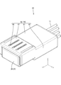
- FIG. 1 is a perspective view showing a joint connector according to the first embodiment.
- FIG. 2 is a perspective view showing a joint connector as viewed from a direction different from that of FIG.
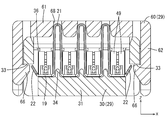
- FIG. 3 is a side sectional view showing a joint connector.
- FIG. 4 is an exploded perspective view showing the lower housing and the upper housing.
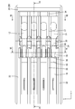
- FIG. 5 is a plan view showing a joint connector in a state before the upper housing is assembled.
- FIG. 6 is a sectional view taken along line VI-VI in FIG.
- FIG. 7 is a sectional view taken along line VII-VII in FIG.
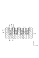
- FIG. 8 is a sectional view taken along line VIII-VIII in FIG.
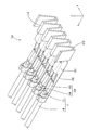
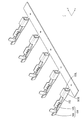
- FIG. 9 is a perspective view showing the joint terminals.
- FIG. 1 is a perspective view showing a joint connector according to the first embodiment.
- FIG. 2 is a perspective view showing a joint connector as viewed from a direction different from that of FIG.
- FIG. 3 is a side sectional view showing a joint
- FIG. 10 is a side sectional view showing a process of sliding the slide portion by a jig.
- FIG. 11 is a perspective view showing a joint terminal showing a state before the carrier is bent.
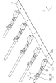
- FIG. 12 is a perspective view showing a joint terminal according to the second embodiment.
- FIG. 13 is a perspective view showing a joint terminal according to the third embodiment.
- FIG. 14 is a perspective view showing a joint terminal according to the fourth embodiment.
- FIG. 15 is a perspective view showing a joint terminal according to the fifth embodiment.
- FIG. 16 is a perspective view showing a joint terminal before the carrier is bent.
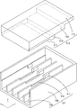
- FIG. 17 is an exploded perspective view showing the lower housing and the upper housing.
- FIG. 18 is a sectional view taken along line XVIII-XVIII in FIG. FIG.
- FIG. 19 is a side sectional view showing a joint connector.
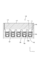
- FIG. 20 is a cross-sectional view taken along the line XX-XX in FIG.
- FIG. 21 is a perspective view showing a joint terminal in a state before the carrier is bent and before the electric wire is crimped.
- the present disclosure is a joint connector for electrically connecting a plurality of electric wires, which includes a housing and joint terminals arranged in the housing, and the joint terminals are arranged along an arrangement direction.
- the connecting portion has a connecting portion connected to the housing, and the connecting portion has a plate shape extending in the arrangement direction and is bent, and the connecting portion engages with the housing.
- the joint terminal By engaging the bent connecting part with the housing, the joint terminal can be easily assembled to the housing. As a result, the efficiency of the assembling work of the joint terminal and the housing can be improved as compared with the case where the joint terminal is press-fitted into the housing, so that the efficiency of the assembling work of the joint connector can be improved.
- the connecting portion has a plurality of bent portions that are bent so as to protrude from the plate surface of the connecting portion, and at least one pitch adjusting bent portion is provided in the plurality of bent portions, and the pitch is described.
- the adjustable bent portion preferably has a bent shape different from that of other bent portions.
- Pitch adjustment By changing the bent shape of the bent part to another bent part, the pitch interval of multiple wire connection parts can be adjusted.
- both end portions of the connecting portion are provided with end engaging portions that engage with the housing.
- the connecting portion has a plurality of bent portions that protrude from the plate surface of the connecting portion and are bent, and the housing is elastically engaged with each of the plurality of bent portions. It is preferable to have a joint.
- the positions of the plurality of bent portions in the arrangement direction can be individually adjusted. Thereby, the accuracy of the pitch interval of the plurality of electric wire connecting portions can be improved.
- Each of the plurality of electric wire connecting portions includes a terminal body having a plurality of sandwiching pieces for sandwiching the electric wire, and a slide portion capable of sliding with respect to the terminal body along the extending direction of the electric wire.
- the slide portion has a tubular shape, and the plurality of holding pieces are accommodated inside the slide portion, and the slide portion is inward from the inner wall of the slide portion. It has a contact portion that pushes the plurality of sandwich pieces toward the electric wire by abutting against the plurality of sandwich pieces, and when the slide portion moves to the contact position, the said hit. It is preferable that the contact portion abuts on the plurality of holding pieces.
- the holding piece is pressed toward the electric wire by the contact portion.
- the electric wire and the electric wire connecting portion can be electrically connected via the holding piece.
- the terminal body preferably has an intersecting wall portion that intersects the slide direction at the front end portion in the slide direction in which the slide portion slides to the contact position.
- each of the plurality of electric wire connecting portions has a crimping portion for crimping to the electric wire.
- the joint terminal and the electric wire can be connected by a simple method called crimping.
- the joint connector 10 electrically connects a plurality of electric wires 11.
- the direction indicated by the arrow Z will be upward
- the direction indicated by the arrow Y will be the front
- the direction indicated by the arrow X will be the left.
- a reference numeral may be given only to a part of the members, and the reference numerals of other members may be omitted.
- the joint connector 10 has a substantially rectangular parallelepiped shape extending in the front-rear direction.
- the joint connector 10 according to the present embodiment includes a housing 29 and a joint terminal 12 arranged in the housing 29.
- the housing 29 includes a lower housing 30 and an upper housing 60 attached to the upper portion of the lower housing 30.
- the electric wires 11 are arranged so as to extend in the front-rear direction, and the front-rear direction is the extension direction of the electric wires 11.
- the core wire 13 As shown in FIG. 3, the plurality of electric wires 11 are arranged so as to extend in the front-rear direction.
- the outer circumference of the core wire 13 of the electric wire 11 is surrounded by an insulating coating 14 made of an insulating synthetic resin.
- the core wire 13 according to the present embodiment is made of one metal wire.
- the core wire 13 may be a stranded wire obtained by twisting a plurality of fine metal wires.
- any metal such as copper, copper alloy, aluminum, and aluminum alloy can be appropriately selected as needed.
- the core wire 13 according to this embodiment is made of copper or a copper alloy.
- the lower housing 30 extends in the front-rear direction and has a flat shape in the vertical direction.
- the lower housing 30 is formed by injection molding an insulating synthetic resin.
- the lower housing 30 has a bottom wall 31, a side wall 32 extending upward from the left and right side edges of the bottom wall 31, and a front wall extending upward from the front end edge of the bottom wall 31.
- a plurality of (four in the present embodiment) partition ribs 34 extending rearward from the front end portion of the bottom wall 31 are formed on the bottom wall 31 of the lower housing 30 at intervals in the left-right direction.
- the length dimension of the partition rib 34 in the front-rear direction is set to be approximately one-third of the length dimension of the bottom wall 31 in the front-rear direction.
- the bottom wall 31 of the lower housing 30 is formed with a plurality of (four in this embodiment) partition walls 35 extending rearward from each rear end of the partition ribs 34.
- the partition wall 35 extends to the rear end of the bottom wall 31.
- the electric wire connecting portion 17 of the joint terminals 12 is arranged from above in the space separated by the side wall 32 of the lower housing 30 and the partition wall 35.
- the connecting portion 19 of the joint terminals 12 is accommodated in the region of the lower housing 30 where the partition rib 34 is provided.
- a locking claw 36 for preventing the joint terminal 12 from coming off upward is formed at a position near the front end portion. Further, a locking claw 36 for preventing the joint terminal 12 from coming off upward is also formed at a position corresponding to the locking claw 36 on the upper edge portion of the side wall 32 of the lower housing 30.
- the locking claw 36 is formed so as to be elastically deformable in the left-right direction.
- a locking recess 33 is formed on the outer surface of the side wall 32 of the lower housing 30 near the front end.
- the upper housing 60 is formed by injection molding an insulating synthetic resin.
- the upper housing 60 has an upper wall 61, a side wall 62 extending downward from the left and right side edges of the upper wall 61, and a rear wall 63 extending downward from the trailing edge of the upper wall 61.
- a lock claw 66 is formed at a position near the front end of the side wall 62 of the upper housing 60.
- the lock claw 66 is formed so as to project inward of the upper housing 60 in the left-right direction.
- the lock claw 66 elastically engages with the locking recess 33 provided on the side wall 32 of the lower housing 30, so that the lower housing 30 and the upper housing 60 can be integrally assembled.
- a side wall 32 of the lower housing 30 and a relief groove 64 for avoiding interference with the partition wall 35 extend upward from the lower end edge of the rear wall 63. It is formed. With the lower housing 30 and the upper housing 60 assembled, the side wall 32 of the lower housing 30 and the partition wall 35 are arranged inside the relief groove 64.
- each electric wire outlet 65 is formed between the escape grooves 64 in the rear wall 63.
- a region approximately one-third from the front end portion of the upper housing 60 is a connecting portion accommodating portion 67 slightly bulging upward.
- a plurality of (three in the present embodiment) escape slits 68 extending in the front-rear direction and arranged at intervals in the left-right direction are formed.
- the upper end portion of the bent portion 21 described later is accommodated in the relief slit 68.
- the joint terminals 12 are arranged at a plurality of (four in the present embodiment) branch portions 20 arranged along the left-right direction (an example of the arrangement direction) and at each of the plurality of branch portions 20. It has a plurality of (four in this embodiment) electric wire connecting portions 17 connected to the continuous electric wire 11, and a connecting portion 19 connecting the plurality of branch portions 20.
- the joint terminal 12 is formed by pressing a metal plate material into a predetermined shape.
- any metal such as copper, copper alloy, aluminum, aluminum alloy, and stainless steel can be appropriately selected as needed.
- the terminal body 15 according to this embodiment is made of copper or a copper alloy.
- a plating layer may be formed on the surface of the joint terminal 12.
- any metal such as tin, nickel, and silver can be appropriately selected as required.
- the joint terminal 12 according to this embodiment is tin-plated.
- the connecting portion 19 is formed by bending a metal plate material elongated in the left-right direction.
- the connecting portion 19 is formed with a plurality of bent portions 21 (three in the present embodiment) that are bent upward in a chevron shape when viewed from the front.
- the bent portion 21 is bent so as to project upward from the plate surface of the connecting portion 19 extending in the front-rear direction and the left-right direction in the state before being bent.
- the left and right ends of the connecting portion 19 are bent diagonally upward to form an end engaging portion 22 that elastically engages with the locking recess 33 of the lower housing 30.
- the bent portion 21 is deformed to open or close in the left-right direction, so that the connecting portion 19 can be elastically expanded and contracted in the left-right direction as a whole. As a result, the connecting portion 19 is compressed or expanded in the left-right direction, so that an elastic force is generated in the connecting portion 19.
- the connecting portion 19 is formed by cutting the elongated carrier 50 to a predetermined length dimension and bending the carrier 50.
- Branch 20 A plurality of (four in this embodiment) branch portions 20 extending rearward are formed in the connecting portion 19.
- the branch portion 20 is formed so as to be elongated in the front-rear direction.
- the bent portion 21 described above is formed in the region of the connecting portion 19 between the portions where the plurality of branch portions 20 are provided.
- a locking wall portion 24 extending upward from the left and right side edges of the branch portion 20 is formed.
- the front end edge of the locking wall portion 24 is bent inward in the left-right direction, and is an intersection wall portion 49 that intersects the front-rear direction.
- the locking wall portion 24 is formed so as to be orthogonal to the front-rear direction.
- the height dimension of the locking wall portion 24 in the vertical direction is set to be approximately half of the height dimension of the bent portion 21.
- An electric wire connecting portion 17 is connected behind the branch portion 20.
- the electric wire connecting portion 17 includes a metal terminal body 15 and a slide portion 16 that can slide and move relative to the terminal body 15.
- the terminal body 15 is formed in a square tubular shape extending in the front-rear direction.
- the terminal body 15 includes an upper holding piece 18A extending rearward from the upper wall of the terminal body 15 and a lower holding piece 18B extending rearward from the lower wall of the terminal body 15.
- the upper holding piece 18A and the lower holding piece 18B have an elongated shape extending back and forth.
- the upper holding piece 18A and the lower holding piece 18B are formed to have substantially the same length dimension in the front-rear direction.
- an upper holding protrusion 23A protruding downward is provided at a position in front of the rear end portion.
- a lower holding protrusion 23B that projects upward is provided at the rear end of the upper surface of the lower holding piece 18B.
- the lower holding protrusion 23B and the upper holding protrusion 23A are provided at positions shifted in the front-rear direction.
- the core wire 13 and the terminal body 15 are electrically connected.
- the slide portion 16 has a square tubular shape extending in the front-rear direction.
- the slide portion 16 is formed by a known method such as cutting, casting, or pressing, if necessary.
- any metal such as copper, copper alloy, aluminum, aluminum alloy, and stainless steel can be appropriately selected as needed.
- the slide portion 16 according to the present embodiment is made of stainless steel.
- a plating layer may be formed on the surface of the slide portion 16.
- any metal such as tin, nickel, and silver can be appropriately selected as required.
- the cross section of the inner shape of the slide portion 16 is the same as or slightly larger than the cross section of the outer shape of the region of the terminal body 15 where the upper holding piece 18A and the lower holding piece 18B are provided. It is formed. As a result, the slide portion 16 is arranged outside the region of the terminal body 15 where the upper holding piece 18A and the lower holding piece 18B are provided. In other words, the upper holding piece 18A and the lower holding piece 18B can be accommodated inside the slide portion 16.
- an upper contact portion 25A (an example of the contact portion) protruding downward is provided on the lower surface of the upper wall of the slide portion 16.
- a lower contact portion 25B (an example of the contact portion) projecting upward is provided.
- a temporary locking receiving portion 26 is opened on the side wall of the slide portion 16 at a position closer to the front end portion in the front-rear direction. Further, on the side wall of the slide portion 16, the main locking receiving portion 27 is opened at a position behind the temporary locking receiving portion 26.
- the temporary locking receiving portion 26 and the main locking receiving portion 27 can be elastically locked with the locking projection 28 provided on the side wall of the terminal body 15.
- the state in which the locking projection 28 of the terminal body 15 and the temporary locking receiving portion 26 of the slide portion 16 are locked is a state in which the slide portion 16 is held at the temporary locking position with respect to the terminal main body 15. ..
- the upper contact portion 25A and the lower contact portion 25B of the slide portion 16 are separated rearward from the rear end edges of the upper holding piece 18A and the lower holding piece 18B of the terminal body 15. Further, in this state, the distance between the upper holding piece 18A and the lower holding piece 18B is set to be larger than the diameter of the core wire 13.
- the slide portion 16 is locked at the main locking position with respect to the terminal main body 15. There is. As shown in FIG. 3, in this state, the upper contact portion 25A of the slide portion 16 is in contact with the upper holding piece 18A from above the upper holding piece 18A. Further, the lower contact portion 25B of the slide portion 16 is in contact with the lower holding piece 18B from below the lower holding piece 18B.
- the slide portion 16 is fitted into the area of the terminal body 15 where the upper holding piece 18A and the lower holding piece 18B are provided, and is fitted into the above-mentioned temporary locking position and the main locking. It can be slid to and from the position.
- the upper holding piece 18A is pressed by the upper holding piece 18A from above by the upper contact portion 25A. Is designed to deform downward. Further, when the lower contact portion 25B presses the lower holding piece 18B from below, the lower holding piece 18B is deformed upward. As a result, the core wire 13 is arranged in the space between the upper holding piece 18A and the lower holding piece 18B in a state of being extended in the front-rear direction (extending direction), and the slide portion 16 is arranged with respect to the terminal body 15.
- the core wire 13 is sandwiched from the vertical direction by the elastically deformed upper holding piece 18A and the lower holding piece 18B. That is, the upper holding piece 18A comes into contact with the core wire 13 from above by being pressed downward by the upper contact portion 25A, and the lower holding piece 18B is pressed upward by the lower contact portion 25B to bring the core wire 13 into contact with the core wire 13. It comes in contact with the cable from below.
- the upper holding protrusion 23A of the upper holding piece 18A presses the core wire 13 from above, and the lower side.
- the lower holding protrusion 23B of the holding piece 18B presses the core wire 13 from below.
- the core wire 13 is pressed from above by the upper holding protrusion 23A and is pressed from below by the lower holding protrusion 23B arranged at a position deviated from the upper holding protrusion 23A in the front-rear direction. Therefore, it is held in a bent state in the vertical direction.
- the core wire 13 and the joint terminal 12 are also electrically connected by the upper holding protrusion 23A and the lower holding protrusion 23B.
- a jig contact portion 46 projecting upward from the upper wall is provided at the front end portion of the slide portion 16.
- the jig 45 comes into contact with the jig contact portion 46 from the rear, and the slide portion 16 is pushed forward by this jig, so that the slide portion 16 can move forward.
- a pair of invitation portions 47 projecting inward of the slide portion 16 are provided on the left and right side walls.
- the invitation portion 47 is formed to be narrower from the rear to the front.
- a carrier 50 elongated in the left-right direction is formed with a plurality of branch portions 20 and an electric wire connecting portion 17 extending rearward.
- the slide portion 16 is held at the temporarily locked position with respect to the terminal body 15.
- both ends of the carrier 50 are bent diagonally upward to form an end engaging portion 22, and the region between the branch portions 20 is bent upward to form a bent portion 21. Is formed.
- the lower housing 30 and the upper housing 60 are formed by injection molding a synthetic resin, respectively.
- the joint terminal 12 is housed in the lower housing 30 from above.
- the locking claw 36 formed on the partition wall 35 of the lower housing 30 elastically locks to the upper edge of the locking wall portion 24 of the joint terminal 12 from above, so that the locking wall portion of the joint terminal 12 24 is held in a state of being held upward with respect to the lower housing 30.
- the connecting portion 19 is slightly compressed in the left-right direction, it is accommodated from above while being along the inner surface of the side wall 32 of the lower housing 30. Then, the tip of the end engaging portion 22 is in sliding contact with the side wall 32 of the lower housing 30. As a result, the joint terminal 12 is smoothly guided to a predetermined position of the lower housing 30. When the end engaging portion 22 reaches the locking recess 33 of the lower housing 30, the connecting portion 19 is restored and deformed, and the end engaging portion 22 is locked to the upper wall of the locking recess 33 from below. As a result, the connecting portion 19 of the joint terminal 12 is held in a state of being held upward with respect to the lower housing 30.
- the core wire 13 of the electric wire 11 is exposed by peeling the insulating coating 14 by a known method. As shown in FIG. 10, the front end portion of the core wire 13 is introduced from the rear end portion of the slide portion 16 into the inside of the slide portion 16. The core wire 13 is guided to the slide portion 16 by coming into contact with the invitation portion 47 of the slide portion 16. When the electric wire 11 is further pushed forward, the front end portion of the core wire 13 enters the inside of the terminal body 15 and reaches the space between the upper holding piece 18A and the lower holding piece 18B.
- the holding jig 48 is arranged in front of the intersecting wall portion 49, the jig 45 is brought into contact with the jig contact portion 46 from the rear, and the slide portion 16 is moved forward. Move the slide. The slide portion 16 is moved forward relative to the terminal body 15. At this time, the locking projection 28 of the terminal body 15 and the temporary locking receiving portion 26 of the slide portion 16 are disengaged, and the side wall of the slide portion 16 rides on the locking projection 28 to expand and deform.
- the upper contact portion 25A of the slide portion 16 abuts on the upper holding piece 18A of the terminal body 15 from above and presses downward.
- the lower contact portion 25B of the slide portion 16 contacts the lower holding piece 18B of the terminal body 15 from below and presses it upward.
- the core wire 13 is sandwiched between the upper holding piece 18A and the lower holding piece 18B from above and below (see FIG. 3).
- the core wire 13 When the core wire 13 is sandwiched between the upper holding piece 18A and the lower holding piece 18B from above and below, the core wire 13 has the upper holding protrusion 23A of the upper holding piece 18A and the lower holding protrusion 18B of the lower holding piece 18B. By being sandwiched between the 23B, the cable is held in a state of being extended in the front-rear direction and in a state of being bent in the vertical direction. As a result, the core wire 13 can be firmly held, so that when a tensile force acts on the electric wire 11, the holding force between the electric wire 11 and the joint terminal 12 can be increased.
- the upper housing 60 is assembled to the lower housing 30 from above.
- the lock claw 66 provided on the side wall 62 of the upper housing 60 is elastically locked to the locking recess 33 provided on the side wall 32 of the lower housing 30, so that the upper housing 60 and the lower housing 30 are integrated. Assembled (see FIG. 8). This completes the joint connector 10.
- the present embodiment is a joint connector 10 for electrically connecting a plurality of electric wires 11, and includes a housing 29 and a joint terminal 12 arranged on the housing 29, and the joint terminal 12 is provided along the left-right direction.
- a plurality of branch portions 20 arranged in a row, a plurality of electric wire connecting portions 17 connected to each of the plurality of branch portions 20 and connected to a plurality of electric wires 11, and a plurality of branch portions 20 by connecting the plurality of branch portions 20.
- It has a connecting portion 19 for electrically connecting the 20s, and the connecting portion 19 has a plate shape extending in the left-right direction and is bent, and the connecting portion 19 engages with the housing 29.
- the joint terminal 12 By engaging the bent connecting portion 19 with the housing 29, the joint terminal 12 can be easily assembled to the housing 29. As a result, the efficiency of the assembling work of the joint terminal 12 and the housing 29 can be improved as compared with the case where the joint terminal 12 is press-fitted into the housing 29, so that the efficiency of the assembling work of the joint connector 10 can be improved. it can.
- end engaging portions 22 that engage with the housing 29 are provided at both ends of the connecting portion 19 in the left-right direction.
- the end engaging portions 22 provided at both ends of the connecting portion 19 are engaged with the housing 29 in a state where the connecting portion 19 is expanded and contracted in the left-right direction to generate elastic force.
- the joint terminal 12 can be attached to the housing 29 by a simple method.
- each of the plurality of electric wire connecting portions 17 has a terminal body 15 having an upper holding piece 18A for holding the electric wire 11 and a lower holding piece 18B, and terminals along the extending direction of the electric wire 11. It has a slide portion 16 that can slide with respect to the main body 15, and the slide portion 16 has a tubular shape, and an upper holding piece 18A and a lower holding piece 18B are housed inside the slide portion 16. The slide portion 16 projects inward from the inner wall of the slide portion 16 and abuts on the upper holding piece 18A and the lower holding piece 18B to bring the upper holding piece 18A and the lower holding piece 18A.
- It has an upper contact portion 25A and a lower contact portion 25B that press the 18B toward the electric wire 11, and when the slide portion 16 moves to the contact position, the upper contact portion 25A and the lower contact portion 25A and the lower contact portion 25B.
- the portion 25B comes into contact with the upper holding piece 18A and the lower holding piece 18B.
- the upper holding piece 18A and the lower holding piece 18B are connected to the electric wire 11 by the upper contact portion 25A and the lower contact portion 25B. Pressed towards.
- the electric wire 11 and the electric wire connecting portion 17 can be electrically connected via the upper holding piece 18A and the lower holding piece 18B.
- the terminal body 15 has an intersecting wall portion 49 intersecting the slide direction at the front end portion in the slide direction in which the slide portion 16 slides to the contact position.
- the slide portion 16 When the slide portion 16 is slid to the contact position, the upper holding piece 18A and the lower holding piece 18B are pushed forward in the sliding direction by the slide portion 16. At this time, by arranging the pressing jig 48 in front of the intersecting wall portion 49 and bringing the pressing jig 48 into contact with the front of the intersecting wall portion 49, the terminal body 15 slides when the sliding portion 16 moves. It is possible to suppress the movement forward in the direction.
- the connecting portion 71 is provided with a bent portion 72A located on the right side and a pitch adjusting bent portion 72B located on the left side.
- the pitch adjustment bent portion 72B is set to have a smaller height dimension in the vertical direction than the bent portion 72A formed on the right side.
- the pitch adjusting bent portion 72B formed on the left side of the connecting portion 71 is set to have a larger width dimension in the left-right direction than the bent portion 72A formed on the right side.
- the joint terminal 70 is formed with three branch portions 20 and three electric wire connecting portions 17 connected to the branch portion 20.
- the pitch intervals of the three electric wire connecting portions 17 in the left-right direction are different. Due to the pitch adjustment bent portion 72B, the pitch interval between the electric wire connecting portion 17 in the center of the connecting portion 71 and the electric wire connecting portion 17 at the left end is set between the electric wire connecting portion 17 in the center and the electric wire at the right end of the connecting portion 71. It is wider than the pitch interval with the connecting portion 17.
- the connecting portion 71 has a plurality of bent portions 72A and 72B that are bent so as to protrude from the plate surface of the connecting portion 71, and at least one pitch adjusting bend is formed in the plurality of bent portions 72A and 72B.
- a portion 72B is provided, and the pitch adjustment bent portion 72B has a bent shape different from that of the other bent portions 72A.
- the pitch interval of a plurality of electric wire connecting portions 17 can be adjusted by making the bent shape of the bent portion 72B different from that of the other bent portions 72A and changing the width dimension in the left-right direction.
- the bent portion 81 formed in the connecting portion 82 is formed by being bent a plurality of times in an M shape when viewed from the front.
- the height dimension of the bent portion 81 in the vertical direction is set to be substantially the same as the height dimension of the jig contact portion 46 of the slide portion 16.
- the height dimension of the joint terminal 80 can be arbitrarily adjusted by adjusting the number of times the bent portion 81 is bent. As a result, it is possible to reduce the height of the joint terminal 80.
- the bent portion 91 is bent in a shape protruding downward from the connecting portion 92. As a result, it is possible to deal with the case where a sufficient space cannot be secured above the connecting portion 92.
- the joint connector 100 according to the fifth embodiment of the present disclosure will be described with reference to FIGS. 15 to 21.
- the upper end edge of the locking wall portion 103R extending upward from the right edge of the branch portion 102 is bent to the left and is branched.
- the upper end edge of the locking wall portion 103L extending upward from the left edge of the portion 102 is bent to the right.
- the locking wall portions 103R and 103L are formed in a square tubular shape extending in the front-rear direction as a whole.
- an electric wire connecting portion 104 is provided behind the branch portion 102.
- the electric wire connecting portion 104 includes a wire barrel portion 105 (an example of a crimping portion) crimping to the outer periphery of the core wire 13 of the electric wire 11 and an insulation barrel portion 106 crimping to the outer periphery of the insulating coating 14 of the electric wire 11. , Are formed side by side.
- the lower housing 107 includes a bottom wall 108, a side wall 109 extending upward from the left and right side edges of the bottom wall 108, and a front wall extending upward from the front end edge of the bottom wall 108. And have.
- the bottom wall 108 is formed with partition walls 110 extending in the front-rear direction arranged side by side at intervals in the left-right direction. As shown in FIG. 19, the joint terminal 101 is held at the upper end edge of the partition wall 110 in a state of being prevented from coming off by locking the joint terminals 101 to the locking wall portions 103R and 103L from above.
- a claw 111 is formed. Further, a locking claw 111 for holding the joint terminal 101 upward in a retaining state is also formed on the inner surface of the side wall 109 of the lower housing 107.
- a first rear stop that projects downward and locks to the bent portion 114 from the rear at a position slightly rearward from the front end portion of the upper wall 113.
- the portion 115 is formed.
- a second back stop 116 is formed slightly behind the first back stop 115 so as to project further downward from the upper wall 113 and lock to the locking walls 103R and 103L from the rear.
- a retractable recess 117 for avoiding interference with the insulation barrel portion 106 is formed in a concave shape upward.
- the partition wall 110 is inserted inside each bent portion 114.
- each bent portion 114 is expanded and deformed, and as a result, an elastic force is generated in each bent portion 114.
- each of the plurality of bent portions 114 elastically sandwiches the partition wall 110.
- the partition wall 110 is an individual engaging portion that elastically engages with each of the plurality of bent portions 114.
- a carrier 50 elongated in the left-right direction is formed in a state in which a plurality of electric wire connecting portions 104 are connected.
- the wire barrel portion 105 is crimped to the outer circumference of the core wire 13, and the insulation barrel portion 106 is crimped to the outer circumference of the insulating coating 14. Further, by bending the carrier 50, a bent portion 114 is formed.
- the joint terminal 101 is assembled from above to the lower housing 107 and held upward in a retaining state.
- the joint connector 100 is completed by assembling the upper housing 112 to the lower housing 107.
- the connecting portion 118 has a plurality of bent portions 114 that project and bend in a direction intersecting the plate surface of the connecting portion 118, and the lower housing 107 is elastic with each of the plurality of bent portions 114. It has a plurality of partition walls 110 that are specifically engaged with each other.
- the positions of the plurality of bent portions 114 in the left-right direction can be individually adjusted. it can. Thereby, the accuracy of the pitch interval of the plurality of electric wire connecting portions 104 can be improved.
- each of the plurality of electric wire connecting portions 104 has a wire barrel portion 105 that is crimped to the core wire 13 of the electric wire 11.
- the joint terminal 101 and the electric wire 11 can be connected by a simple method of crimping.
- the joint terminal 70 may be provided with two or more pitch adjusting bent portions 72B.
- the slide portion 16 may have a polygonal tubular shape such as a triangular tubular shape or a hexagonal tubular shape, or may have a cylindrical shape, and any shape can be adopted.
Landscapes
- Engineering & Computer Science (AREA)
- Manufacturing & Machinery (AREA)
- Connections Effected By Soldering, Adhesion, Or Permanent Deformation (AREA)
- Connector Housings Or Holding Contact Members (AREA)
- Connections By Means Of Piercing Elements, Nuts, Or Screws (AREA)
Abstract
複数の電線11を電気的に接続するジョイントコネクタ10であって、ハウジング29と、前記ハウジング29に配設されるジョイント端子12と、を備え、前記ジョイント端子12は、配列方向に沿って配列された複数の分岐部20と、前記複数の分岐部20のそれぞれに連なり前記複数の電線11と接続される複数の電線接続部17と、前記複数の分岐部20を連結することにより前記複数の分岐部20を電気的に接続する連結部19と、を有し、前記連結部19は、前記配列方向に延びる板状をなすとともに折れ曲がっており、前記連結部19が前記ハウジング29と係合するジョイントコネクタ10。
Description
本開示は、ジョイントコネクタに関する。
ジョイントコネクタとして、特開平7-73938号公報に記載のものが知られている。このジョイントコネクタは、ハウジングと、複数のタブ状接触部が連結されたジョイント端子とを備える。ジョイント端子はハウジングに設けられた端子取付溝部内に圧入される。
上記の技術にかかるジョイントコネクタにおいては、ジョイント端子がハウジングに圧入されるため、ジョイント端子とハウジングとの組み付け作業の効率が低下するという問題があった。
本開示は上記のような事情に基づいて完成されたものであって、組み立て作業の効率が向上されたジョイントコネクタを提供することを目的とする。
本開示は、複数の電線を電気的に接続するジョイントコネクタであって、ハウジングと、前記ハウジングに配設されるジョイント端子と、を備え、前記ジョイント端子は、配列方向に沿って配列された複数の分岐部と、前記複数の分岐部のそれぞれに連なり前記複数の電線と接続される複数の電線接続部と、前記複数の分岐部を連結することにより前記複数の分岐部を電気的に接続する連結部と、を有し、前記連結部は、前記配列方向に延びる板状をなすとともに折れ曲がっており、前記連結部が前記ハウジングと係合する。
本開示によれば、ジョイントコネクタの組み立て作業の効率を向上させることができる。
[本開示の実施形態の説明]
最初に本開示の実施態様を列挙して説明する。
最初に本開示の実施態様を列挙して説明する。
(1)本開示は、複数の電線を電気的に接続するジョイントコネクタであって、ハウジングと、前記ハウジングに配設されるジョイント端子と、を備え、前記ジョイント端子は、配列方向に沿って配列された複数の分岐部と、前記複数の分岐部のそれぞれに連なり前記複数の電線と接続される複数の電線接続部と、前記複数の分岐部を連結することにより前記複数の分岐部を電気的に接続する連結部と、を有し、前記連結部は、前記配列方向に延びる板状をなすとともに折れ曲がっており、前記連結部が前記ハウジングと係合することが好ましい。
折れ曲がった連結部を、ハウジングに係合させることにより、ジョイント端子をハウジングに容易に組み付けることができる。これにより、ジョイント端子をハウジングに圧入する場合に比べて、ジョイント端子とハウジングとの組み付け作業の効率を向上させることができるので、ジョイントコネクタの組み立て作業の効率を向上させることができる。
(2)前記連結部は、前記連結部の板面から突出して折れ曲がった複数の折れ曲がり部を有し、前記複数の折れ曲がり部には、少なくとも1つのピッチ調節折れ曲がり部が設けられており、前記ピッチ調節折れ曲がり部は、他の折れ曲がり部とは異なる折れ曲がり形状を有することが好ましい。
ピッチ調節折れ曲がり部の折れ曲がり形状を、他の折れ曲がり部と変更することにより、複数の電線接続部のピッチ間隔を調節することができる。
(3)前記配列方向について前記連結部の両端部には、前記ハウジングと係合する端部係合部が設けられていることが好ましい。
上記の構成によれば、連結部を配列方向に伸縮させて弾発力を発生させた状態で、連結部の両端部に設けられた端部係合部をハウジングに係合させるという簡易な手法により、ジョイント端子をハウジングに取り付けることができる。
(4)前記連結部は、前記連結部の板面から突出して折れ曲がった複数の折れ曲がり部を有し、前記ハウジングは、前記複数の折れ曲がり部のそれぞれと弾性的に係合する、複数の個別係合部を有することが好ましい。
連結部に設けられた折れ曲がり部と、ハウジングに設けられた個別係合部とが、それぞれ係合することにより、複数の折れ曲がり部の、配列方向の位置を個別に調節することができる。これにより、複数の電線接続部のピッチ間隔の精度を向上させることができる。
(5)前記複数の電線接続部のそれぞれは、前記電線を挟持する複数の挟持片を備えた端子本体と、前記電線の延びる方向に沿って前記端子本体に対してスライド移動可能なスライド部と、を有し、前記スライド部は筒状をなしており、前記スライド部の内部に前記複数の挟持片が収容されるようになっており、前記スライド部は、前記スライド部の内壁から内方に突出するとともに、前記複数の挟持片に当接することによって前記複数の挟持片を前記電線に向かって押圧する当接部を有し、前記スライド部が当接位置に移動したときに、前記当接部が前記複数の挟持片に当接することが好ましい。
上記の構成によれば、スライド部を当接位置にスライド移動させることにより、当接部によって挟持片が電線に向かって押圧される。これにより、電線と電線接続部とを、挟持片を介して電気的に接続できる。
(6)前記端子本体は、前記スライド部が前記当接位置にスライドするスライド方向の前端部に、前記スライド方向と交差する交差壁部を有することが好ましい。
スライド部を当接位置にスライド移動させる際に、スライド部によって挟持片がスライド方向の前方に押される。このとき、交差壁部の前方に押え治具を配して、この押え治具を、交差壁部の前方から当接させることにより、端子本体がスライド方向の前方に移動することを抑制できる。これにより、スライド部を当接位置にスライド移動させる際に、端子本体がスライド方向の前方に位置ずれすることを抑制できる。
(7)前記複数の電線接続部のそれぞれは、前記電線に圧着する圧着部を有することが好ましい。
ジョイント端子と電線とを、圧着という簡易な手法により接続できる。
[本開示の実施形態の詳細]
以下に、本開示の実施形態について説明する。本開示はこれらの例示に限定されるものではなく、特許請求の範囲によって示され、特許請求の範囲と均等の意味および範囲内での全ての変更が含まれることが意図される。
以下に、本開示の実施形態について説明する。本開示はこれらの例示に限定されるものではなく、特許請求の範囲によって示され、特許請求の範囲と均等の意味および範囲内での全ての変更が含まれることが意図される。
<実施形態1>
本開示の実施形態1について、図1から図11を参照しつつ説明する。本実施形態にかかるジョイントコネクタ10は、複数の電線11を電気的に接続する。以下の説明では、矢線Zの示す向きを上とし、矢線Yの示す向きを前とし、矢線Xの示す向きを左として説明する。なお、複数の同一部材については、一部の部材にのみ符号を付し、他の部材の符号を省略する場合がある。
本開示の実施形態1について、図1から図11を参照しつつ説明する。本実施形態にかかるジョイントコネクタ10は、複数の電線11を電気的に接続する。以下の説明では、矢線Zの示す向きを上とし、矢線Yの示す向きを前とし、矢線Xの示す向きを左として説明する。なお、複数の同一部材については、一部の部材にのみ符号を付し、他の部材の符号を省略する場合がある。
[ジョイントコネクタ10]
図1および図2に示されるように、ジョイントコネクタ10は前後方向に延びる略直方体形状をなしている。図3に示されるように、本実施形態にかかるジョイントコネクタ10は、ハウジング29と、ハウジング29内に配設されるジョイント端子12と、を備える。図4に示されるように、ハウジング29は、ロアハウジング30と、ロアハウジング30の上部に取り付けられるアッパーハウジング60と、を備える。電線11は概ね前後方向に延びて配索されており、前後方向が電線11の延び方向とされる。
図1および図2に示されるように、ジョイントコネクタ10は前後方向に延びる略直方体形状をなしている。図3に示されるように、本実施形態にかかるジョイントコネクタ10は、ハウジング29と、ハウジング29内に配設されるジョイント端子12と、を備える。図4に示されるように、ハウジング29は、ロアハウジング30と、ロアハウジング30の上部に取り付けられるアッパーハウジング60と、を備える。電線11は概ね前後方向に延びて配索されており、前後方向が電線11の延び方向とされる。
[電線11]
図3に示されるように、複数の電線11は前後方向に延びて配されている。電線11は、芯線13の外周を絶縁性の合成樹脂からなる絶縁被覆14で包囲されている。本実施形態にかかる芯線13は、1本の金属線からなる。なお、芯線13は複数の金属細線が撚り合わされてなる撚線であってもよい。芯線13を構成する金属は、銅、銅合金、アルミニウム、アルミニウム合金等、必要に応じて任意の金属を適宜に選択できる。本実施形態にかかる芯線13は銅、または銅合金からなる。
図3に示されるように、複数の電線11は前後方向に延びて配されている。電線11は、芯線13の外周を絶縁性の合成樹脂からなる絶縁被覆14で包囲されている。本実施形態にかかる芯線13は、1本の金属線からなる。なお、芯線13は複数の金属細線が撚り合わされてなる撚線であってもよい。芯線13を構成する金属は、銅、銅合金、アルミニウム、アルミニウム合金等、必要に応じて任意の金属を適宜に選択できる。本実施形態にかかる芯線13は銅、または銅合金からなる。
[ロアハウジング30]
図4に示されるように、ロアハウジング30は、前後方向に延びるとともに上下に扁平な形状をなしている。ロアハウジング30は、絶縁性の合成樹脂が射出成型されて形成される。ロアハウジング30は、底壁31と、底壁31の左右両側縁から上方に延びる側壁32と、底壁31の前端縁から上方に延びる前壁と、を有する。
図4に示されるように、ロアハウジング30は、前後方向に延びるとともに上下に扁平な形状をなしている。ロアハウジング30は、絶縁性の合成樹脂が射出成型されて形成される。ロアハウジング30は、底壁31と、底壁31の左右両側縁から上方に延びる側壁32と、底壁31の前端縁から上方に延びる前壁と、を有する。
図4に示されるように、ロアハウジング30の底壁31には、底壁31の前端部から後方に延びる複数(本実施形態では4つ)の仕切りリブ34が左右方向に間隔を空けて形成されている。仕切りリブ34の前後方向の長さ寸法は、底壁31の前後方向の長さ寸法の略三分の一に設定されている。
ロアハウジング30の底壁31には、仕切りリブ34の各後端部から後方に延びる複数(本実施形態では4つ)の仕切り壁35が形成されている。仕切り壁35は、底壁31の後端部に至るまで延びている。
図5に示されるように、ロアハウジング30の側壁32、および仕切り壁35によって区切られた空間内には、ジョイント端子12のうち電線接続部17が上方から配置されるようになっている。ロアハウジング30のうち、仕切りリブ34が設けられた領域には、ジョイント端子12のうち連結部19が収容されるようになっている。
図6に示されるように、仕切り壁35の上縁部には、前端部寄りの位置に、ジョイント端子12を上方に抜け止めするための係止爪36が形成されている。また、ロアハウジング30の側壁32の上縁部にも、係止爪36に対応する位置に、ジョイント端子12を上方に抜け止めするための係止爪36が形成されている。係止爪36は左右方向に弾性変形可能に形成されている。
図4および図7に示されるように、ロアハウジング30の側壁32の外面には、前端部寄りの部分に、係止凹部33が形成されている。
[アッパーハウジング60]
図3に示されるように、ロアハウジング30は、上方から組み付けられたアッパーハウジング60によって、上部が覆われるようになっている。アッパーハウジング60は絶縁性の合成樹脂を射出成型することによって形成される。
図3に示されるように、ロアハウジング30は、上方から組み付けられたアッパーハウジング60によって、上部が覆われるようになっている。アッパーハウジング60は絶縁性の合成樹脂を射出成型することによって形成される。
アッパーハウジング60は、上壁61と、上壁61の左右両側縁から下方に延びる側壁62と、上壁61の後縁から下方に延びる後壁63と、を有する。
図4に示されるように、アッパーハウジング60の側壁62の前端部寄りの位置にはロック爪66が形成されている。ロック爪66は、左右方向についてアッパーハウジング60の内方に突出するように形成されている。このロック爪66が、ロアハウジング30の側壁32に設けられた係止凹部33と弾性的に係合することにより、ロアハウジング30とアッパーハウジング60とが一体に組み付けられるようになっている。
図1に示されるように、アッパーハウジング60の後壁63には、ロアハウジング30の側壁32、および仕切り壁35との干渉を避ける逃げ溝64が、後壁63の下端縁から上方に延びて形成されている。ロアハウジング30とアッパーハウジング60とが組み付けられた状態で、ロアハウジング30の側壁32、および仕切り壁35は、逃げ溝64の内側に配されるようになっている。
図1に示されるように、アッパーハウジング60の後壁63には、電線11が後方に導出される複数(本実施形態では4つ)の電線導出口65が左右方向に間隔を空けて並んで形成されている。各電線導出口65は、後壁63のうち、逃げ溝64の間に形成されている。
図2に示されるように、アッパーハウジング60の前端部から略三分の一の領域は、上方にやや膨出した連結部収容部67とされる。アッパーハウジング60の上壁61のうち連結部収容部67に対応する領域には、前後方向に延びるとともに左右方向に間隔を空けて並ぶ、複数(本実施形態では3つ)の逃げスリット68が形成されている。図8に示されるように、ロアハウジング30とアッパーハウジング60とが組み付けられた状態で、後述する折れ曲がり部21の上端部が逃げスリット68内に収容されるようになっている。これにより、折れ曲がり部21の上端部と上壁61とが干渉することを回避できる。
[ジョイント端子12]
図9に示されるように、ジョイント端子12は、左右方向(配列方向の一例)に沿って配列された複数(本実施形態では4つ)の分岐部20と、複数の分岐部20のそれぞれに連なり電線11と接続される複数(本実施形態では4つ)の電線接続部17と、複数の分岐部20を連結する連結部19と、を有する。
図9に示されるように、ジョイント端子12は、左右方向(配列方向の一例)に沿って配列された複数(本実施形態では4つ)の分岐部20と、複数の分岐部20のそれぞれに連なり電線11と接続される複数(本実施形態では4つ)の電線接続部17と、複数の分岐部20を連結する連結部19と、を有する。
ジョイント端子12は金属板材を所定の形状にプレス加工することにより形成される。ジョイント端子12を構成する金属は、銅、銅合金、アルミニウム、アルミニウム合金、ステンレス鋼等、必要に応じて任意の金属を適宜に選択できる。本実施形態にかかる端子本体15は、銅、または銅合金からなる。ジョイント端子12の表面にはめっき層が形成されていてもよい。めっき層を構成する金属は、スズ、ニッケル、銀等必要に応じて任意の金属を適宜に選択できる。本実施形態にかかるジョイント端子12にはスズめっきが施されている。
[連結部19]
連結部19は、左右方向に細長く延びた金属板材が折り曲げられて形成されている。連結部19には、前方から見て、上方に山形に屈曲した複数(本実施形態では3つ)の折れ曲がり部21が形成されている。換言すると、折れ曲がり部21は、折り曲げられる前の状態の、前後方向および左右方向に広がる連結部19の板面から、上方に突出するように折れ曲がっている。連結部19の左右両端部は、斜め上方に曲がっており、ロアハウジング30の係止凹部33に弾性的に係合する端部係合部22とされる。
連結部19は、左右方向に細長く延びた金属板材が折り曲げられて形成されている。連結部19には、前方から見て、上方に山形に屈曲した複数(本実施形態では3つ)の折れ曲がり部21が形成されている。換言すると、折れ曲がり部21は、折り曲げられる前の状態の、前後方向および左右方向に広がる連結部19の板面から、上方に突出するように折れ曲がっている。連結部19の左右両端部は、斜め上方に曲がっており、ロアハウジング30の係止凹部33に弾性的に係合する端部係合部22とされる。
折れ曲がり部21が左右方向について開き変形または閉じ変形することにより、連結部19は、全体として、左右方向について弾性的に伸縮可能になっている。この結果、連結部19が左右方向に圧縮または伸長されることにより、連結部19に弾発力が生じるようになっている。連結部19は、細長く延びたキャリア50が所定の長さ寸法に切断されるとともに、折り曲げ加工されることにより形成される。
[分岐部20]
連結部19には、後方に延びる複数(本実施形態では4つ)の分岐部20が形成されている。分岐部20は前後方向に細長く延びて形成されている。連結部19のうち、複数の分岐部20が設けられている部分の間の領域には、上記した折れ曲がり部21が形成されている。
連結部19には、後方に延びる複数(本実施形態では4つ)の分岐部20が形成されている。分岐部20は前後方向に細長く延びて形成されている。連結部19のうち、複数の分岐部20が設けられている部分の間の領域には、上記した折れ曲がり部21が形成されている。
分岐部20の後半部分には、分岐部20の左右両側縁から上方に延びる係止壁部24が形成されている。係止壁部24の前端縁は、左右方向の内方に曲がっており、前後方向と交差する交差壁部49とされる。本実施形態では、係止壁部24は、前後方向に直交するように形成されている。係止壁部24の上下方向に高さ寸法は、折れ曲がり部21の高さ寸法の略二分の一に設定されている。分岐部20の後方には、電線接続部17が連なっている。
[電線接続部17]
電線接続部17は、金属製の端子本体15と、端子本体15に対して相対的にスライド移動可能なスライド部16と、を備える。
電線接続部17は、金属製の端子本体15と、端子本体15に対して相対的にスライド移動可能なスライド部16と、を備える。
[端子本体15]
図3に示されるように、端子本体15は前後方向に延びる角筒状に形成されている。端子本体15は、端子本体15の上壁から後方に延出された上側挟持片18Aと、端子本体15の下壁から後方に延出された下側挟持片18Bと、を備える。上側挟持片18Aと下側挟持片18Bは前後に延びた細長い形状をなしている。上側挟持片18Aと下側挟持片18Bの前後方向の長さ寸法は略同じに形成されている。
図3に示されるように、端子本体15は前後方向に延びる角筒状に形成されている。端子本体15は、端子本体15の上壁から後方に延出された上側挟持片18Aと、端子本体15の下壁から後方に延出された下側挟持片18Bと、を備える。上側挟持片18Aと下側挟持片18Bは前後に延びた細長い形状をなしている。上側挟持片18Aと下側挟持片18Bの前後方向の長さ寸法は略同じに形成されている。
上側挟持片18Aの下面には、後端部よりも前方の位置に、下方に突出する上側保持突部23Aが設けられている。下側挟持片18Bの上面の後端部には、上方に突出する下側保持突部23Bが設けられている。下側保持突部23Bと、上側保持突部23Aとは、前後方向についてずれた位置に設けられている。
上側挟持片18Aの下面、および下側挟持片18Bの上面が、芯線13の表面に形成された酸化被膜に食い込んで酸化被膜を剥がすことにより、芯線13の金属表面を露出させるようになっている。この金属表面と、上側挟持片18Aおよび下側挟持片18Bとが接触することにより、芯線13と端子本体15とが電気的に接続される。
[スライド部16]
図9に示されるように、スライド部16は、前後方向に延びる角筒状をなしている。スライド部16は、切削加工、鋳造、プレス加工等、必要に応じて公知の手法により形成される。スライド部16を構成する金属は、銅、銅合金、アルミニウム、アルミニウム合金、ステンレス鋼等、必要に応じて任意の金属を適宜に選択できる。本実施形態にかかるスライド部16は、ステンレス鋼からなる。スライド部16の表面にはめっき層が形成されていてもよい。めっき層を構成する金属は、スズ、ニッケル、銀等必要に応じて任意の金属を適宜に選択できる。
図9に示されるように、スライド部16は、前後方向に延びる角筒状をなしている。スライド部16は、切削加工、鋳造、プレス加工等、必要に応じて公知の手法により形成される。スライド部16を構成する金属は、銅、銅合金、アルミニウム、アルミニウム合金、ステンレス鋼等、必要に応じて任意の金属を適宜に選択できる。本実施形態にかかるスライド部16は、ステンレス鋼からなる。スライド部16の表面にはめっき層が形成されていてもよい。めっき層を構成する金属は、スズ、ニッケル、銀等必要に応じて任意の金属を適宜に選択できる。
図3に示されるように、スライド部16の内形状の断面は、端子本体15のうち、上側挟持片18Aと下側挟持片18Bが設けられた領域の外形状の断面と同じか、やや大きく形成されている。これにより、スライド部16は、端子本体15のうち、上側挟持片18Aと下側挟持片18Bとが設けられた領域の外方に配されるようになっている。換言すると、スライド部16の内部に、上側挟持片18Aと下側挟持片18Bが収容可能になっている。
図3に示されるように、スライド部16の上壁の下面には、下方に突出する上側当接部25A(当接部の一例)が設けられている。スライド部16の下壁の上面には、上方に突出する下側当接部25B(当接部の一例)が設けられている。
図9に示されるように、スライド部16の側壁には、前後方向の前端部寄りの位置に、仮係止受け部26が開口されている。また、スライド部16の側壁には、仮係止受け部26よりも後方の位置に、本係止受け部27が開口されている。仮係止受け部26と、本係止受け部27は、端子本体15の側壁に設けられた係止突起28と弾性的に係止可能になっている。
端子本体15の係止突起28とスライド部16の仮係止受け部26とが係止した状態は、端子本体15に対してスライド部16が仮係止位置に保持された状態となっている。この状態においては、スライド部16の上側当接部25Aおよび下側当接部25Bは、端子本体15の上側挟持片18Aおよび下側挟持片18Bの後端縁から後方に離れている。また、この状態においては、上側挟持片18Aと下側挟持片18Bとの間の間隔は、芯線13の直径よりも大きく設定されている。
端子本体15の係止突起28とスライド部16の本係止受け部27とが係止した状態は、端子本体15に対してスライド部16が本係止位置に係止された状態となっている。図3に示されるように、この状態においては、スライド部16の上側当接部25Aは、上側挟持片18Aの上方から上側挟持片18Aに接触している。また、スライド部16の下側当接部25Bは、下側挟持片18Bの下方から下側挟持片18Bに接触している。
上記のように、スライド部16は、端子本体15のうち上側挟持片18Aと下側挟持片18Bとが設けられた領域に外嵌された状態で、上記した仮係止位置と、本係止位置との間をスライド移動可能になっている。
図3に示されるように、スライド部16が端子本体15に対して本係止位置で保持された状態では、上側当接部25Aが上方から上側挟持片18Aを押圧することによって上側挟持片18Aが下方に変形するようになっている。また、下側当接部25Bが下方から下側挟持片18Bを押圧することによって下側挟持片18Bが上方に変形するようになっている。これにより、上側挟持片18Aと下側挟持片18Bとの間の空間に、芯線13を前後方向(延び方向)に延びた状態で配し、且つ、スライド部16が端子本体15に対して本係止位置で保持した状態では、芯線13は、弾性変形した上側挟持片18Aと下側挟持片18Bによって上下方向から挟持されるようになっている。すなわち、上側挟持片18Aは上側当接部25Aに下方に押圧されることにより芯線13に上方から接触し、下側挟持片18Bは下側当接部25Bに上方に押圧されることにより芯線13に下方から接触するようになっている。
図3に示されるように、スライド部16が端子本体15に対して本係止位置で保持された状態では、上側挟持片18Aの上側保持突部23Aが芯線13を上方から押圧し、下側挟持片18Bの下側保持突部23Bが芯線13を下方から押圧する。このように、芯線13は、上側保持突部23Aによって上方から押圧されるとともに、上側保持突部23Aと前後方向にずれた位置に配された下側保持突部23Bによって下方から押圧されることにより、上下方向について屈曲した状態に保持される。また、上側保持突部23Aと、下側保持突部23Bとによっても、芯線13とジョイント端子12とが電気的に接続されるようになっている。
図10に示されるように、スライド部16の前端部には、上壁から上方に突出する治具接触部46が設けられている。治具接触部46に後方から治具45が接触して、この治具によってスライド部16が前方に押されることにより、スライド部16が前方に移動可能になっている。
図9に示されるように、スライド部16の後端部寄りの位置には、左右両側壁に、スライド部16の内方に突出する一対の誘い込み部47が設けられている。誘い込み部47は、後方から前方に向かうに従って幅狭に形成されている。誘い込み部47の内面に芯線13が摺接することにより、芯線13はスライド部16の内部へと案内される。
[ジョイントコネクタ10の組み立て工程]
続いて、本実施形態にかかるジョイントコネクタ10の組み立て工程の例について説明する。ジョイントコネクタ10の組み立て工程は以下の記述に限定されない。
続いて、本実施形態にかかるジョイントコネクタ10の組み立て工程の例について説明する。ジョイントコネクタ10の組み立て工程は以下の記述に限定されない。
図11に示されるように、金属板材がプレス加工されることにより、左右方向に細長く延びたキャリア50から、複数の分岐部20、および電線接続部17が後方に延びた状態のものが形成される。この状態では、スライド部16は、端子本体15に対して仮係止位置に保持されている。
図9に示されるように、キャリア50の両端部が斜め上方に折り曲げられて端部係合部22が形成されるとともに、分岐部20の間の領域が上方に屈曲されることにより折れ曲がり部21が形成される。
図4に示されるように、合成樹脂を射出成型することにより、ロアハウジング30とアッパーハウジング60とそれぞれ形成される。
図5、図6、および図7に示されるように、ロアハウジング30に上方からジョイント端子12が収容される。ロアハウジング30の仕切り壁35に形成された係止爪36が、ジョイント端子12の係止壁部24の上縁部に上方から弾性的に係止することにより、ジョイント端子12の係止壁部24がロアハウジング30に対して上方へ抜け止めされた状態で保持される。
また、連結部19を左右方向にやや圧縮した状態で、ロアハウジング30の側壁32の内面に沿わせながら、上方から収容する。すると、端部係合部22の先端は、ロアハウジング30の側壁32と摺接する。これにより、ジョイント端子12がロアハウジング30の所定の位置までスムーズに案内される。端部係合部22がロアハウジング30の係止凹部33に達すると、連結部19が復帰変形し、端部係合部22が係止凹部33の上壁に下方から係止する。これにより、ジョイント端子12の連結部19がロアハウジング30に対して上方へ抜け止めされた状態で保持される。
公知の手法で絶縁被覆14が皮剥ぎ加工されることにより電線11の芯線13が露出される。図10に示されるように、芯線13の前端部が、スライド部16の後端部からスライド部16の内部へと導入される。芯線13はスライド部16の誘い込み部47と当接することにより、スライド部16へと案内される。さらに電線11が前方に押し込まれると、芯線13の前端部は端子本体15の内部へと進入して上側挟持片18Aと下側挟持片18Bとの間の空間内に至る。
次に、図10に示されるように、押え治具48を交差壁部49の前方に配置するとともに、治具45を後方から治具接触部46に当接させて、スライド部16を前方にスライド移動させる。スライド部16は端子本体15に対して相対的に前方に移動させられる。このとき、端子本体15の係止突起28と、スライド部16の仮係止受け部26との係止が外れ、スライド部16の側壁が係止突起28に乗り上げて拡開変形する。
スライド部16が前方に移動させられると、スライド部16の側壁が復帰変形して端子本体15の係止突起28と、スライド部16の本係止受け部27とが弾性的に係止する。これによりスライド部16が端子本体15に対して本係止位置に保持される。
スライド部16が端子本体15に対して本係止位置に保持された状態で、スライド部16の上側当接部25Aが、端子本体15の上側挟持片18Aに上方から当接して下方へと押圧する。また、スライド部16の下側当接部25Bが、端子本体15の下側挟持片18Bに下方から当接して上方へと押圧する。これにより、芯線13が、上側挟持片18Aと下側挟持片18Bに上下から挟持される(図3参照)。
図3に示されるように、上側挟持片18Aの下面と、下側挟持片18Bの上面とに芯線13が挟まれることにより、芯線13の表面に形成された酸化被膜が剥がされ、芯線13を構成する金属表面が露出する。この金属表面と、上側挟持片18Aおよび下側挟持片18Bが接触することにより、電線11とジョイント端子12とが電気的に接続される。これにより、複数の電線11が、ジョイント端子12を介して電気的に接続される。
芯線13が上側挟持片18Aと下側挟持片18Bに上下から挟持された状態においては、芯線13は、上側挟持片18Aの上側保持突部23Aと、下側挟持片18Bの下側保持突部23Bとに挟まれることにより、前後方向に延びた状態で、且つ、上下方向に屈曲した状態で保持される。これにより、芯線13を強固に保持することができるので、電線11に引っ張り力が作用した場合に、電線11とジョイント端子12との保持力を高めることができる。
治具45によってスライド部16が前方に押されると、端子本体15および分岐部20も前方に押される。このとき、交差壁部49が押え治具48に後方から当接することにより、端子本体15および分岐部20が前方に移動することが抑制されるようになっている。ジョイント端子12と電線とが電気的に接続された後、押え治具48が取り外される。
図3に示されるように、アッパーハウジング60がロアハウジング30に上方から組み付けられる。アッパーハウジング60の側壁62に設けられたロック爪66が、ロアハウジング30の側壁32に設けられた係止凹部33に弾性的に係止することにより、アッパーハウジング60とロアハウジング30とが一体に組み付けられる(図8参照)。これによりジョイントコネクタ10が完成する。
[本実施形態の作用効果]
続いて、本実施形態の作用効果について説明する。本実施形態は、複数の電線11を電気的に接続するジョイントコネクタ10であって、ハウジング29と、ハウジング29に配設されるジョイント端子12と、を備え、ジョイント端子12は、左右方向に沿って配列された複数の分岐部20と、複数の分岐部20のそれぞれに連なり複数の電線11と接続される複数の電線接続部17と、複数の分岐部20を連結することにより複数の分岐部20を電気的に接続する連結部19と、を有し、連結部19は、左右方向に延びる板状をなすとともに折れ曲がっており、連結部19がハウジング29と係合する。
続いて、本実施形態の作用効果について説明する。本実施形態は、複数の電線11を電気的に接続するジョイントコネクタ10であって、ハウジング29と、ハウジング29に配設されるジョイント端子12と、を備え、ジョイント端子12は、左右方向に沿って配列された複数の分岐部20と、複数の分岐部20のそれぞれに連なり複数の電線11と接続される複数の電線接続部17と、複数の分岐部20を連結することにより複数の分岐部20を電気的に接続する連結部19と、を有し、連結部19は、左右方向に延びる板状をなすとともに折れ曲がっており、連結部19がハウジング29と係合する。
折れ曲がった連結部19を、ハウジング29に係合させることにより、ジョイント端子12をハウジング29に容易に組み付けることができる。これにより、ジョイント端子12をハウジング29に圧入する場合に比べて、ジョイント端子12とハウジング29との組み付け作業の効率を向上させることができるので、ジョイントコネクタ10の組み立て作業の効率を向上させることができる。
また、本実施形態によれば、左右方向について連結部19の両端部には、ハウジング29と係合する端部係合部22が設けられている。
上記の構成によれば、連結部19を左右方向に伸縮させて弾発力を発生させた状態で、連結部19の両端部に設けられた端部係合部22をハウジング29に係合させるという簡易な手法により、ジョイント端子12をハウジング29に取り付けることができる。
本実施形態によれば、複数の電線接続部17のそれぞれは、電線11を挟持する上側挟持片18A、および下側挟持片18Bを備えた端子本体15と、電線11の延びる方向に沿って端子本体15に対してスライド移動可能なスライド部16と、を有し、スライド部16は筒状をなしており、スライド部16の内部に上側挟持片18A、および下側挟持片18Bが収容されるようになっており、スライド部16は、スライド部16の内壁から内方に突出するとともに、上側挟持片18A、および下側挟持片18Bに当接することによって上側挟持片18A、および下側挟持片18Bを電線11に向かって押圧する上側当接部25A、および下側当接部25Bを有し、スライド部16が当接位置に移動したときに、上側当接部25A、および下側当接部25Bが上側挟持片18A、および下側挟持片18Bに当接する。
上記の構成によれば、スライド部16を当接位置にスライド移動させることにより、上側当接部25A、および下側当接部25Bによって上側挟持片18A、および下側挟持片18Bが電線11に向かって押圧される。これにより、電線11と電線接続部17とを、上側挟持片18A、および下側挟持片18Bを介して電気的に接続できる。
また、本実施形態によれば、端子本体15は、スライド部16が当接位置にスライドするスライド方向の前端部に、スライド方向と交差する交差壁部49を有する。
スライド部16を当接位置にスライド移動させる際に、スライド部16によって上側挟持片18A、および下側挟持片18Bがスライド方向の前方に押される。このとき、交差壁部49の前方に押え治具48を配して、この押え治具48を、交差壁部49の前方から当接させることにより、スライド部16の移動時に端子本体15がスライド方向の前方に移動することを抑制できる。
<実施形態2>
次に、本開示の実施形態2について、図12を参照しつつ説明する。本実施形態にかかるジョイント端子70においては、連結部71には、右側に位置する折れ曲がり部72Aと、左側に位置するピッチ調節折れ曲がり部72Bとが設けられている。ピッチ調節折れ曲がり部72Bは、右側に形成された折れ曲がり部72Aよりも、上下方向の高さ寸法が小さく設定されている。また、連結部71の左側に形成されたピッチ調節折れ曲がり部72Bは、右側に形成された折れ曲がり部72Aよりも、左右方向の幅寸法が大きく設定されている。
次に、本開示の実施形態2について、図12を参照しつつ説明する。本実施形態にかかるジョイント端子70においては、連結部71には、右側に位置する折れ曲がり部72Aと、左側に位置するピッチ調節折れ曲がり部72Bとが設けられている。ピッチ調節折れ曲がり部72Bは、右側に形成された折れ曲がり部72Aよりも、上下方向の高さ寸法が小さく設定されている。また、連結部71の左側に形成されたピッチ調節折れ曲がり部72Bは、右側に形成された折れ曲がり部72Aよりも、左右方向の幅寸法が大きく設定されている。
本実施形態にかかるジョイント端子70には、3つの分岐部20と、この分岐部20に連なる3つの電線接続部17が形成されている。3つの電線接続部17の、左右方向のピッチ間隔は異なっている。ピッチ調節折れ曲がり部72Bによって、連結部71のうち中央の電線接続部17と、左端部の電線接続部17とのピッチ間隔は、連結部71のうち中央の電線接続部17と、右端部の電線接続部17とのピッチ間隔よりも広くなっている。
上記以外の構成については、実施形態1と略同様なので、同一部材については同一符号を付し、重複する説明を省略する。
本実施形態によれば、連結部71は、連結部71の板面から突出して折れ曲がった複数の折れ曲がり部72A,72Bを有し、複数の折れ曲がり部72A,72Bには、少なくとも1つのピッチ調節折れ曲がり部72Bが設けられており、ピッチ調節折れ曲がり部72Bは、他の折れ曲がり部72Aとは異なる折れ曲がり形状を有する。
ピッチ調節折れ曲がり部72Bの折れ曲がり形状を、他の折れ曲がり部72Aと異ならせ、左右方向の幅寸法を変えることにより、複数の電線接続部17のピッチ間隔を調節することができる。
<実施形態3>
次に、本開示の実施形態3について、図13を参照しつつ説明する。本実施形態にかかるジョイント端子80においては、連結部82に形成された折れ曲がり部81は、前方から見てM字形状に複数回屈曲して形成されている。これにより、折れ曲がり部81の上下方向の高さ寸法は、スライド部16の治具接触部46の高さ寸法と略同じに設定されている。このように、折れ曲がり部81の折れ曲がり回数を調節することにより、ジョイント端子80の高さ寸法を任意に調節することができる。この結果、ジョイント端子80を低背化することも可能となる。
次に、本開示の実施形態3について、図13を参照しつつ説明する。本実施形態にかかるジョイント端子80においては、連結部82に形成された折れ曲がり部81は、前方から見てM字形状に複数回屈曲して形成されている。これにより、折れ曲がり部81の上下方向の高さ寸法は、スライド部16の治具接触部46の高さ寸法と略同じに設定されている。このように、折れ曲がり部81の折れ曲がり回数を調節することにより、ジョイント端子80の高さ寸法を任意に調節することができる。この結果、ジョイント端子80を低背化することも可能となる。
<実施形態4>
次に、本開示の実施形態4について、図14を参照しつつ説明する。本実施形態にかかるジョイント端子90においては、折れ曲がり部91は、連結部92の下方に突出した形状に折れ曲がっている。これにより、連結部92の上方にスペースが十分に確保できない場合に対応することができる。
次に、本開示の実施形態4について、図14を参照しつつ説明する。本実施形態にかかるジョイント端子90においては、折れ曲がり部91は、連結部92の下方に突出した形状に折れ曲がっている。これにより、連結部92の上方にスペースが十分に確保できない場合に対応することができる。
<実施形態5>
次に、本開示の実施形態5にかかるジョイントコネクタ100について、図15から図21を参照しつつ説明する。図15および図16に示されるように、本実施形態にかかるジョイント端子101においては、分岐部102の右側縁から上方に延びた係止壁部103Rの上端縁は左方に折れ曲がっており、分岐部102の左側縁から上方に延びた係止壁部103Lの上端縁は右方に折れ曲がっている。これにより、係止壁部103R、103Lは全体として、前後方向に延びる角筒状に形成されている。
次に、本開示の実施形態5にかかるジョイントコネクタ100について、図15から図21を参照しつつ説明する。図15および図16に示されるように、本実施形態にかかるジョイント端子101においては、分岐部102の右側縁から上方に延びた係止壁部103Rの上端縁は左方に折れ曲がっており、分岐部102の左側縁から上方に延びた係止壁部103Lの上端縁は右方に折れ曲がっている。これにより、係止壁部103R、103Lは全体として、前後方向に延びる角筒状に形成されている。
図15に示されるように、分岐部102の後方には電線接続部104が設けられている。本実施形態にかかる電線接続部104は、電線11の芯線13の外周に圧着するワイヤーバレル部105(圧着部の一例)と、電線11の絶縁被覆14の外周に圧着するインシュレーションバレル部106と、が前後に並んで形成されている。
図17に示されるように、本実施形態にかかるロアハウジング107は、底壁108と、底壁108の左右両側縁から上方に延びる側壁109と、底壁108の前端縁から上方に延びる前壁と、を有する。
底壁108には、前後方向に延びる仕切り壁110が左右方向に間隔を空けて並んで形成されている。図19に示されるように、仕切り壁110の上端縁には、ジョイント端子101の係止壁部103R,103Lに上方から係止することにより、ジョイント端子101を上方へ抜け止め状態で保持する係止爪111が形成されている。また、ロアハウジング107の側壁109の内面にも、ジョイント端子101を上方へ抜け止め状態で保持する係止爪111が形成されている。
図19に示されるように、アッパーハウジング112の上壁113の下面には、上壁113の前端部からやや後方の位置に、下方に突出して折れ曲がり部114に後方から係止する第1後ろ止め部115が形成されている。第1後ろ止め部115のやや後方には、上壁113からさらに下方に突出して、係止壁部103R,103Lに後方から係止する第2後ろ止め部116が形成されている。これにより、電線11が後方に引っ張られた場合においても、ジョイント端子101が後方に移動することを抑制できる。
第2後ろ止め部116のやや後方の位置には、インシュレーションバレル部106との干渉を避けるための退避凹部117が上方に凹状に形成されている。
図20に示されるように、本実施形態においては、各折れ曲がり部114の内部に仕切り壁110が入り込むようになっている。これにより、各折れ曲がり部114が拡開変形する結果、各折れ曲がり部114に弾発力が発生する。この結果、複数の折れ曲がり部114のそれぞれが、仕切り壁110を弾性的に挟み込むようになっている。本実施系形態においては、仕切り壁110が、複数の折れ曲がり部114のそれぞれと弾性的に係合する個別係合部とされる。
上記以外の構成については、実施形態1と略同様なので、同一部材については同一符号を付し、重複する説明を省略する。
本実施形態にかかるジョイントコネクタ100の組み立て工程の例について説明する。ジョイントコネクタ100の組み立て工程は以下の記述に限定されない。
図21に示されるように、金属板材がプレス加工されることにより、左右方向に細長く延びたキャリア50に複数の電線接続部104が連なった状態のものが形成される。
図15に示されるように、皮剥ぎされた電線11の端部において、芯線13の外周にワイヤーバレル部105が圧着され、絶縁被覆14の外周にインシュレーションバレル部106が圧着される。また、キャリア50が曲げられることにより、折れ曲がり部114が形成される。
図18および図20に示されるように、ロアハウジング107に上方からジョイント端子101を組み付けて、上方へ抜け止め状態で保持する。
図19に示されるように、ロアハウジング107にアッパーハウジング112を組み付けることにより、ジョイントコネクタ100が完成する。
本実施形態によれば、連結部118は、連結部118の板面に交差する方向に突出して折れ曲がった複数の折れ曲がり部114を有し、ロアハウジング107は、複数の折れ曲がり部114のそれぞれと弾性的に係合する、複数の仕切り壁110を有する。
連結部118に設けられた折れ曲がり部114と、ロアハウジング107に設けられた仕切り壁110とが、それぞれ係合することにより、複数の折れ曲がり部114の、左右方向の位置を個別に調節することができる。これにより、複数の電線接続部104のピッチ間隔の精度を向上させることができる。
本実施形態によれば、複数の電線接続部104のそれぞれは、電線11の芯線13に圧着するワイヤーバレル部105を有する。
これにより、ジョイント端子101と電線11とを、圧着という簡易な手法により接続できる。
<他の実施形態>
(1)ジョイント端子12には、2つ、または5つ以上の、任意の個数の電線接続部17を形成することができる。
(1)ジョイント端子12には、2つ、または5つ以上の、任意の個数の電線接続部17を形成することができる。
(2)ジョイント端子70には、2つ以上の複数のピッチ調節折れ曲がり部72Bを設けてもよい。
(3)スライド部16は、三角筒状、六角筒状等の多角筒状でもよく、円筒形状でもよく任意の形状を採用できる。
10,100: ジョイントコネクタ
11: 電線
12,70,80,90,101: ジョイント端子
13: 芯線
14: 絶縁被覆
15: 端子本体
16: スライド部
17,104: 電線接続部
18A: 上側挟持片
18B: 下側挟持片
19,71,82,92,118: 連結部
20,102: 分岐部
21,81,91,114: 折れ曲がり部
22: 端部係合部
23A: 上側保持突部
23B: 下側保持突部
24,103R,103L: 係止壁部
25A: 上側当接部
25B: 下側当接部
26: 仮係止受け部
27: 本係止受け部
28: 係止突起
29: ハウジング
30,107: ロアハウジング
31,108: 底壁
32,109: 側壁
33: 係止凹部
34: 仕切りリブ
35,110: 仕切り壁
36,111: 係止爪
45: 治具
46: 治具接触部
47: 誘い込み部
48: 押え治具
49: 交差壁部
50: キャリア
60,112: アッパーハウジング
61,113: 上壁
62: 側壁
63: 後壁
64: 逃げ溝
65: 電線導出口
66: ロック爪
67: 連結部収容部
68: 逃げスリット
72A: 折れ曲がり部
72B: ピッチ調節折れ曲がり部
105: ワイヤーバレル部(圧着部)
106: インシュレーションバレル部
115: 第1後ろ止め部
116: 第2後ろ止め部
117: 退避凹部
11: 電線
12,70,80,90,101: ジョイント端子
13: 芯線
14: 絶縁被覆
15: 端子本体
16: スライド部
17,104: 電線接続部
18A: 上側挟持片
18B: 下側挟持片
19,71,82,92,118: 連結部
20,102: 分岐部
21,81,91,114: 折れ曲がり部
22: 端部係合部
23A: 上側保持突部
23B: 下側保持突部
24,103R,103L: 係止壁部
25A: 上側当接部
25B: 下側当接部
26: 仮係止受け部
27: 本係止受け部
28: 係止突起
29: ハウジング
30,107: ロアハウジング
31,108: 底壁
32,109: 側壁
33: 係止凹部
34: 仕切りリブ
35,110: 仕切り壁
36,111: 係止爪
45: 治具
46: 治具接触部
47: 誘い込み部
48: 押え治具
49: 交差壁部
50: キャリア
60,112: アッパーハウジング
61,113: 上壁
62: 側壁
63: 後壁
64: 逃げ溝
65: 電線導出口
66: ロック爪
67: 連結部収容部
68: 逃げスリット
72A: 折れ曲がり部
72B: ピッチ調節折れ曲がり部
105: ワイヤーバレル部(圧着部)
106: インシュレーションバレル部
115: 第1後ろ止め部
116: 第2後ろ止め部
117: 退避凹部
Claims (7)
- 複数の電線を電気的に接続するジョイントコネクタであって、
ハウジングと、
前記ハウジングに配設されるジョイント端子と、を備え、
前記ジョイント端子は、配列方向に沿って配列された複数の分岐部と、前記複数の分岐部のそれぞれに連なり前記複数の電線と接続される複数の電線接続部と、前記複数の分岐部を連結することにより前記複数の分岐部を電気的に接続する連結部と、を有し、
前記連結部は、前記配列方向に延びる板状をなすとともに折れ曲がっており、
前記連結部が前記ハウジングと係合するジョイントコネクタ。 - 前記連結部は、前記連結部の板面から突出して折れ曲がった複数の折れ曲がり部を有し、
前記複数の折れ曲がり部には、少なくとも1つのピッチ調節折れ曲がり部が設けられており、
前記ピッチ調節折れ曲がり部は、他の折れ曲がり部とは異なる折れ曲がり形状を有する請求項1に記載のジョイントコネクタ。 - 前記配列方向について前記連結部の両端部には、前記ハウジングと係合する端部係合部が設けられている請求項1または請求項2に記載のジョイントコネクタ。
- 前記連結部は、前記連結部の板面から突出して折れ曲がった複数の折れ曲がり部を有し、
前記ハウジングは、前記複数の折れ曲がり部のそれぞれと弾性的に係合する、複数の個別係合部を有する請求項1から請求項3のいずれか1項に記載のジョイントコネクタ。 - 前記複数の電線接続部のそれぞれは、
前記電線を挟持する複数の挟持片を備えた端子本体と、
前記電線の延びる方向に沿って前記端子本体に対してスライド移動可能なスライド部と、を有し、
前記スライド部は筒状をなしており、前記スライド部の内部に前記複数の挟持片が収容されるようになっており、
前記スライド部は、前記スライド部の内壁から内方に突出するとともに、前記複数の挟持片に当接することによって前記複数の挟持片を前記電線に向かって押圧する当接部を有し、
前記スライド部が当接位置に移動したときに、前記当接部が前記複数の挟持片に当接する請求項1から請求項4のいずれか1項に記載のジョイントコネクタ。 - 前記端子本体は、前記スライド部が前記当接位置にスライドするスライド方向の前端部に、前記スライド方向と交差する交差壁部を有する請求項5に記載のジョイントコネクタ。
- 前記複数の電線接続部のそれぞれは、前記電線に圧着する圧着部を有する請求項1から請求項6のいずれか1項に記載のジョイントコネクタ。
Priority Applications (2)
| Application Number | Priority Date | Filing Date | Title |
|---|---|---|---|
| CN202080072986.7A CN114641902B (zh) | 2019-10-24 | 2020-08-18 | 接头连接器 |
| US17/767,029 US12237607B2 (en) | 2019-10-24 | 2020-08-18 | Joint connector including branch portions and coupling portion |
Applications Claiming Priority (2)
| Application Number | Priority Date | Filing Date | Title |
|---|---|---|---|
| JP2019-193602 | 2019-10-24 | ||
| JP2019193602A JP7255449B2 (ja) | 2019-10-24 | 2019-10-24 | ジョイントコネクタ |
Publications (1)
| Publication Number | Publication Date |
|---|---|
| WO2021079596A1 true WO2021079596A1 (ja) | 2021-04-29 |
Family
ID=75620446
Family Applications (1)
| Application Number | Title | Priority Date | Filing Date |
|---|---|---|---|
| PCT/JP2020/031060 Ceased WO2021079596A1 (ja) | 2019-10-24 | 2020-08-18 | ジョイントコネクタ |
Country Status (4)
| Country | Link |
|---|---|
| US (1) | US12237607B2 (ja) |
| JP (1) | JP7255449B2 (ja) |
| CN (1) | CN114641902B (ja) |
| WO (1) | WO2021079596A1 (ja) |
Families Citing this family (2)
| Publication number | Priority date | Publication date | Assignee | Title |
|---|---|---|---|---|
| JP7476825B2 (ja) * | 2021-03-08 | 2024-05-01 | 株式会社オートネットワーク技術研究所 | コネクタ |
| CN116924159B (zh) * | 2023-07-11 | 2026-01-02 | 惠科股份有限公司 | 收纳机构和显示装置 |
Citations (4)
| Publication number | Priority date | Publication date | Assignee | Title |
|---|---|---|---|---|
| JP2000306645A (ja) * | 1999-04-21 | 2000-11-02 | Sumitomo Wiring Syst Ltd | ジョイントコネクタ |
| JP2001135368A (ja) * | 1999-10-29 | 2001-05-18 | Fujikura Ltd | 圧接ジョイント端子用ハウジング及びそれを用いたジョイントコネクタ |
| JP2013168301A (ja) * | 2012-02-16 | 2013-08-29 | Yazaki Corp | ジョイントコネクタ |
| JP2019145208A (ja) * | 2018-02-15 | 2019-08-29 | 株式会社オートネットワーク技術研究所 | 端子、及びコネクタ |
Family Cites Families (18)
| Publication number | Priority date | Publication date | Assignee | Title |
|---|---|---|---|---|
| US4274700A (en) * | 1977-10-12 | 1981-06-23 | Bunker Ramo Corporation | Low cost electrical connector |
| JPH0878117A (ja) * | 1994-08-31 | 1996-03-22 | Yazaki Corp | ジョイントコネクタ |
| JP3274250B2 (ja) | 1993-09-01 | 2002-04-15 | 矢崎総業株式会社 | ジョイントコネクタおよびジョイント端子 |
| JP3225801B2 (ja) * | 1995-08-01 | 2001-11-05 | 住友電装株式会社 | ジョイントターミナル |
| JP3530046B2 (ja) * | 1998-11-13 | 2004-05-24 | 矢崎総業株式会社 | ジョイントコネクタ |
| US7419409B2 (en) * | 2003-06-18 | 2008-09-02 | Mitsubishi Cable Industries Ltd. | Connection terminal |
| JP2005123098A (ja) * | 2003-10-20 | 2005-05-12 | Fujikura Ltd | ジョイントコネクタ |
| JP2005160235A (ja) * | 2003-11-27 | 2005-06-16 | Yazaki Corp | ジョイントコネクタ |
| JP2005183340A (ja) * | 2003-12-24 | 2005-07-07 | Sumitomo Wiring Syst Ltd | ジョイントコネクタ |
| JP4075825B2 (ja) * | 2004-02-26 | 2008-04-16 | 住友電装株式会社 | 雌端子金具 |
| DE102006040824B4 (de) * | 2006-08-31 | 2013-03-28 | Lisa Dräxlmaier GmbH | Stromverteiler zum Ausgleichen einer Toleranz |
| JP5140407B2 (ja) * | 2007-12-18 | 2013-02-06 | 株式会社オートネットワーク技術研究所 | ジョイントコネクタ |
| JP6206392B2 (ja) * | 2014-12-25 | 2017-10-04 | 株式会社オートネットワーク技術研究所 | ジョイントコネクタ |
| JP2016207487A (ja) * | 2015-04-23 | 2016-12-08 | 株式会社オートネットワーク技術研究所 | ジョイントコネクタ |
| JP2017130421A (ja) * | 2016-01-22 | 2017-07-27 | 山一電機株式会社 | コンタクト端子、コンタクト支持体、および、それを備える接続装置 |
| JP6370341B2 (ja) * | 2016-07-21 | 2018-08-08 | 矢崎総業株式会社 | コネクタ |
| JP6915858B2 (ja) * | 2017-08-08 | 2021-08-04 | 日本圧着端子製造株式会社 | コネクタ |
| WO2019235389A1 (ja) * | 2018-06-05 | 2019-12-12 | 株式会社オートネットワーク技術研究所 | ジョイントコネクタ |
-
2019
- 2019-10-24 JP JP2019193602A patent/JP7255449B2/ja active Active
-
2020
- 2020-08-18 US US17/767,029 patent/US12237607B2/en active Active
- 2020-08-18 CN CN202080072986.7A patent/CN114641902B/zh active Active
- 2020-08-18 WO PCT/JP2020/031060 patent/WO2021079596A1/ja not_active Ceased
Patent Citations (4)
| Publication number | Priority date | Publication date | Assignee | Title |
|---|---|---|---|---|
| JP2000306645A (ja) * | 1999-04-21 | 2000-11-02 | Sumitomo Wiring Syst Ltd | ジョイントコネクタ |
| JP2001135368A (ja) * | 1999-10-29 | 2001-05-18 | Fujikura Ltd | 圧接ジョイント端子用ハウジング及びそれを用いたジョイントコネクタ |
| JP2013168301A (ja) * | 2012-02-16 | 2013-08-29 | Yazaki Corp | ジョイントコネクタ |
| JP2019145208A (ja) * | 2018-02-15 | 2019-08-29 | 株式会社オートネットワーク技術研究所 | 端子、及びコネクタ |
Also Published As
| Publication number | Publication date |
|---|---|
| CN114641902A (zh) | 2022-06-17 |
| JP7255449B2 (ja) | 2023-04-11 |
| JP2021068616A (ja) | 2021-04-30 |
| CN114641902B (zh) | 2024-04-16 |
| US12237607B2 (en) | 2025-02-25 |
| US20220368056A1 (en) | 2022-11-17 |
Similar Documents
| Publication | Publication Date | Title |
|---|---|---|
| JP6592127B2 (ja) | 端子金具 | |
| US11228152B2 (en) | Joint connector | |
| US4963102A (en) | Electrical connector of the hermaphroditic type | |
| US11394136B2 (en) | Terminal | |
| US20160285187A1 (en) | Multi-contact terminal | |
| US11165172B2 (en) | Terminal and wire with terminal | |
| US7607944B2 (en) | Multi-pole coaxial connector | |
| US20100071953A1 (en) | Joint connector, joint terminal and a wiring harness with a joint connector | |
| JP7088109B2 (ja) | ジョイントコネクタ | |
| JP7092259B2 (ja) | コネクタ | |
| EP1608045A2 (en) | A shielded connector and method of connecting it with a shielded conductor path | |
| JP6801626B2 (ja) | 電線保持部材 | |
| WO2021079596A1 (ja) | ジョイントコネクタ | |
| JP7088110B2 (ja) | ジョイントコネクタ | |
| JP2595011Y2 (ja) | ソケット型多極コネクタ | |
| FR2893767A1 (fr) | Ensemble de bornes en chaine,procede pour sa fabrication et appareil pour son sertissage | |
| US20220376428A1 (en) | Joint connector | |
| JP2020068125A (ja) | 端子、及び、端子に電線を接続する方法 | |
| WO2020209177A1 (ja) | ジョイントコネクタ | |
| US5419709A (en) | Shielded connector | |
| US4032211A (en) | Multi-conductor half-tap connection | |
| EP0818065B1 (en) | Electrical connector assembly comprising an electrical connector and a shield assembly | |
| US20250286302A1 (en) | Connector and connector manufacturing method | |
| CN111755877A (zh) | 连接器 |
Legal Events
| Date | Code | Title | Description |
|---|---|---|---|
| 121 | Ep: the epo has been informed by wipo that ep was designated in this application |
Ref document number: 20880175 Country of ref document: EP Kind code of ref document: A1 |
|
| NENP | Non-entry into the national phase |
Ref country code: DE |
|
| 122 | Ep: pct application non-entry in european phase |
Ref document number: 20880175 Country of ref document: EP Kind code of ref document: A1 |
|
| WWG | Wipo information: grant in national office |
Ref document number: 17767029 Country of ref document: US |