WO2021075432A1 - 内燃機関の制御装置及び制御方法 - Google Patents
内燃機関の制御装置及び制御方法 Download PDFInfo
- Publication number
- WO2021075432A1 WO2021075432A1 PCT/JP2020/038652 JP2020038652W WO2021075432A1 WO 2021075432 A1 WO2021075432 A1 WO 2021075432A1 JP 2020038652 W JP2020038652 W JP 2020038652W WO 2021075432 A1 WO2021075432 A1 WO 2021075432A1
- Authority
- WO
- WIPO (PCT)
- Prior art keywords
- blow
- internal combustion
- combustion engine
- control device
- gas
- Prior art date
- Legal status (The legal status is an assumption and is not a legal conclusion. Google has not performed a legal analysis and makes no representation as to the accuracy of the status listed.)
- Ceased
Links
Images




Classifications
-
- F—MECHANICAL ENGINEERING; LIGHTING; HEATING; WEAPONS; BLASTING
- F01—MACHINES OR ENGINES IN GENERAL; ENGINE PLANTS IN GENERAL; STEAM ENGINES
- F01M—LUBRICATING OF MACHINES OR ENGINES IN GENERAL; LUBRICATING INTERNAL COMBUSTION ENGINES; CRANKCASE VENTILATING
- F01M13/00—Crankcase ventilating or breathing
-
- F—MECHANICAL ENGINEERING; LIGHTING; HEATING; WEAPONS; BLASTING
- F02—COMBUSTION ENGINES; HOT-GAS OR COMBUSTION-PRODUCT ENGINE PLANTS
- F02D—CONTROLLING COMBUSTION ENGINES
- F02D41/00—Electrical control of supply of combustible mixture or its constituents
- F02D41/02—Circuit arrangements for generating control signals
- F02D41/04—Introducing corrections for particular operating conditions
- F02D41/12—Introducing corrections for particular operating conditions for deceleration
-
- Y—GENERAL TAGGING OF NEW TECHNOLOGICAL DEVELOPMENTS; GENERAL TAGGING OF CROSS-SECTIONAL TECHNOLOGIES SPANNING OVER SEVERAL SECTIONS OF THE IPC; TECHNICAL SUBJECTS COVERED BY FORMER USPC CROSS-REFERENCE ART COLLECTIONS [XRACs] AND DIGESTS
- Y02—TECHNOLOGIES OR APPLICATIONS FOR MITIGATION OR ADAPTATION AGAINST CLIMATE CHANGE
- Y02T—CLIMATE CHANGE MITIGATION TECHNOLOGIES RELATED TO TRANSPORTATION
- Y02T10/00—Road transport of goods or passengers
- Y02T10/10—Internal combustion engine [ICE] based vehicles
- Y02T10/40—Engine management systems
Definitions
- the present invention relates to an internal combustion engine control device and a control method for controlling an internal combustion engine for a vehicle provided with a blow-by gas recirculation passage and an electronically controlled valve device provided in the blow-by gas recirculation passage.
- the intake control device for an internal combustion engine disclosed in Patent Document 1 includes a throttle valve for adjusting the flow rate of fresh air supplied from the outside to the combustion chamber and a PCV (Positive Crankcase) including blow-by gas supplied from the engine body to the intake passage. Ventilation)
- a PCV valve for adjusting the flow rate of gas is provided, and a control means for operating the PCV valve in the valve closing direction and the throttle valve in the valve opening direction is provided based on the start of fuel cutting.
- the blow-by gas accumulated in the blow-by gas recirculation passage or the like at the end of the fuel cut is blow-by gas.
- the present invention has been made in view of the conventional circumstances, and an object of the present invention is the amount of particulate matter emitted from the internal combustion engine when the supply of blow-by gas to the combustion chamber is restarted based on the end of the fuel cut. It is an object of the present invention to provide a control device and a control method for an internal combustion engine, which can prevent an increase in the amount of fuel and a sudden change in the output torque of the internal combustion engine.
- the electronically controlled valve device provided in the blow-by gas recirculation passage is operated in the valve closing direction based on the start of fuel cut in the internal combustion engine.
- the blow-by gas retention amount responds to the response of the operation of the electronically controlled valve device in the valve opening direction based on the end of the fuel cut and the operation of the electronically controlled valve device in the valve opening direction based on the end of the fuel cut. The more it is, the slower it is.
- FIG. 1 is a diagram showing an aspect of an internal combustion engine for a vehicle to which a control device and a control method for an internal combustion engine according to the present invention are applied.
- the internal combustion engine 1 shown in FIG. 1 is a spark-ignition gasoline engine used as a power source for a vehicle, and the engine main body 1a is provided with an ignition device 4, a fuel injection device 5, and the like.
- the fuel injection device 5 is arranged in the inlet manifold 2a and injects gasoline as fuel into the inlet manifold 2a.
- the intake air of the internal combustion engine 1 flows into the combustion chamber 10 together with the fuel injected by the fuel injection device 5 through the air cleaner 7, the electronically controlled throttle device 8, and the intake valve 19.
- the electronically controlled throttle device 8 is a device that opens and closes the throttle valve 8a with the throttle motor 8b, and adjusts the intake air amount of the internal combustion engine 1.
- the electronically controlled throttle device 8 includes a throttle opening sensor 8c that outputs a signal corresponding to the throttle opening TPS.
- the exhaust gas purification catalyst device 12 is arranged in the exhaust duct 3a, and purifies the exhaust gas of the internal combustion engine 1 by a three-way catalyst or the like.
- the rotation speed detecting device 6 outputs a signal of the rotation angle NE for each predetermined rotation angle of the crankshaft 14A by detecting the protrusion of the ring gear 14.
- the flow rate detection device 9 is arranged on the upstream side of the electronically controlled throttle device 8 and outputs a signal corresponding to the intake air flow rate QAR of the internal combustion engine 1.
- the oil temperature sensor 11 outputs a signal corresponding to the oil temperature TL, which is the temperature of the lubricating oil of the internal combustion engine 1.
- the outside air temperature sensor 15 outputs a signal corresponding to the outside air temperature TO, in other words, the air temperature outside the vehicle.
- the electronic odometer 16 measures the total mileage of the vehicle and outputs a signal corresponding to the total mileage ML.
- the intake pressure sensor 17 outputs a signal corresponding to the intake pressure PB, which is the pressure downstream of the electronically controlled throttle device 8.
- the control device 13 which is an electronic control device equipped with a microcomputer, captures detection signals such as throttle opening TPS, intake air flow rate QAR, rotation angle NE, oil temperature TL, outside air temperature TO, and integrated mileage ML. Then, the control device 13 calculates the fuel injection pulse width TI [ms] and the injection timing based on the captured sensor detection signal, and sends a valve opening command signal corresponding to the fuel injection pulse width TI to the fuel injection device 5 at the injection timing.
- the software includes a function of outputting and controlling the fuel injection amount and injection timing by the fuel injection device 5.
- control device 13 implements a fuel cut that temporarily stops the fuel injection by the fuel injection device 5 in the deceleration operation state of the internal combustion engine 1. For example, when the driver takes his / her foot off the accelerator pedal and the engine rotation speed is higher than the first threshold value, the control device 13 determines that the condition for starting the fuel cut is satisfied and injects fuel by the fuel injection device 5. Stop it.
- the control device 13 restarts the fuel injection by the fuel injection device 5 when the engine rotation speed falls below the second threshold value (second threshold value ⁇ first threshold value) while the fuel injection by the fuel injection device 5 is stopped. Also, when the driver depresses the accelerator pedal, the fuel injection by the fuel injection device 5 is restarted. Further, the control device 13 generates and outputs a command signal of the ignition device 4 and the electronically controlled throttle device 8, controls the ignition timing of the ignition device 4, the opening degree of the throttle valve 8a, and the like, and operates the internal combustion engine 1. To control.
- the control device 13 has an analog input circuit 20, an A / D conversion circuit 21, a digital input circuit 22, an output circuit 23, and the like, in order to input and output data such as measurement results of various sensors and operation amounts to be output to various devices.
- the I / O circuit 24 is provided.
- the control device 13 includes a microcomputer 31 including an MPU (Microprocessor Unit) 26, a ROM (Read Only Memory) 27, and a RAM (Random Access Memory) 28 in order to perform data arithmetic processing.
- MPU Microprocessor Unit
- ROM Read Only Memory
- RAM Random Access Memory
- the analog input circuit 20 acquires analog signals related to the intake air flow rate QAR, throttle opening TPS, oil temperature TL, outside temperature TO, intake pressure PB, and the like, and supplies the acquired analog signals to the A / D conversion circuit 21.
- the A / D conversion circuit 21 converts the acquired analog signal into a digital signal and outputs it on the bus 25.
- the digital input circuit 22 acquires digital signals related to the rotation angle NE, the integrated mileage ML, and the like, and outputs the acquired digital signals to the bus 25 via the I / O circuit 24.
- the MPU 26, ROM 27, RAM 28, timer / counter 29, and the like are connected to the bus 25. Then, the MPU 26, the ROM 27, and the RAM 28 exchange data via the bus 25.
- the clock generator 30 supplies a clock signal to the MPU 26, and the MPU 26 executes various calculations and processes in synchronization with the clock signal.
- the ROM 27 is composed of, for example, an EEPROM (Electrically Erasable Programmable Read-Only Memory) capable of erasing and rewriting data, and stores a program for operating the control device 13, setting data, initial values, and the like. The information stored in the ROM 27 is read into the RAM 28 and the MPU 26 via the bus 25.
- EEPROM Electrically Erasable Programmable Read-Only Memory
- the RAM 28 is used as a work area for temporarily storing the calculation result and the processing result by the MPU 26.
- the timer / counter 29 is used for measuring time, measuring various times, and the like. After being output on the bus 25, the calculation result and the processing result by the MPU 26 are supplied from the output circuit 23 to the ignition device 4, the fuel injection device 5, the electronically controlled throttle device 8, and the like via the I / O circuit 24.
- the internal combustion engine 1 includes a blow-by gas recirculation device 41.
- the blow-by gas recirculation device 41 is a device for returning blow-by gas containing vaporized fuel among unburned fuels leaked from the combustion chamber 10 of the internal combustion engine 1 into the crankcase 42 for storing the lubricating oil to the intake passage of the internal combustion engine 1. Is.
- the blow-by gas recirculation device 41 includes a first blow-by gas recirculation passage 43 that communicates the inside of the crankcase 42 with the inside of the intake collector portion 2b downstream of the electronically controlled throttle device 8, and an intake passage and a crankcase upstream of the electronically controlled throttle device 8.
- a second blow-by gas recirculation passage 45 communicating with the 42 and a PCV valve 44 provided in the first blow-by gas recirculation passage 43 are provided.
- the PCV valve 44 is an electronically controlled valve device that has an actuator such as an electric motor that is driven and controlled by the control device 13 and is driven to open and close by the actuator to adjust the opening degree.
- the lubricating oil of the internal combustion engine 1 is stored in the oil pan provided at the lower part of the crankcase 42.
- the control device 13 opens the PCV valve 44. Then, the blow-by gas in the crankcase 42 is brought to the downstream of the electronically controlled throttle device 8 via the first blow-by gas recirculation passage 43 due to the differential pressure generated between the downstream of the electronically controlled throttle device 8 and the inside of the crankcase 42. It is supplied and burned in the combustion chamber 10.
- the opening degree control of the PCV valve 44 by the control device 13 will be described in detail.
- the control device 13 operates the electronically controlled throttle device 8 to reduce the negative pressure in the combustion chamber 10, suppresses the amount of lubricating oil sucked into the combustion chamber 10, and suppresses the amount of lubricating oil sucked into the combustion chamber 10.
- the amount of fresh air supplied to the combustion chamber 10 by the valve opening operation of the electronically controlled throttle device 8 is increased, while the amount of blow-by gas supplied to the combustion chamber 10 by the valve closing operation of the PCV valve 44. Is reduced. Therefore, it is possible to prevent the amount of gas supplied to the combustion chamber 10 from deviating from the required amount during the execution of the fuel cut.
- the first blow-by responds to the valve opening operation of the PCV valve 44. It is slower as the amount of blow-by gas retained in the gas recirculation passage 43 or the like is larger. As a result, a large amount of blow-by gas that has accumulated in the first blow-by gas recirculation passage 43 or the like in the fully closed state of the PCV valve 44 flows into the combustion chamber 10 as the PCV valve 44 is opened, and is in the form of particles. It suppresses an increase in the amount of substances emitted and a sudden change in the output torque of the internal combustion engine 1.
- the blow-by gas stays in the intake collector 2b after being returned to the upstream of the electronically controlled throttle device 8 via the second blow-by gas recirculation passage 45 when the internal combustion engine 1 is heavily loaded, so that the PCV valve is retained when the load is high. It includes a portion that the 44 is closed and stays in the first blow-by gas recirculation passage 43, and a portion that stays in the crankcase 42 during the fuel cut in which the PCV valve 44 is closed.
- FIG. 2 is a flowchart showing the operation procedure of the PCV valve 44 during the fuel cut and at the end of the fuel cut, which is carried out by the control device 13. The process shown in the flowchart of FIG. 2 is periodically executed by the control device 13.
- the control device 13 performs a process of calculating the blow-by gas retention amount BGR in step S101.
- the control device 13 applies the blow-by gas staying in each of the intake collector portion 2b, the first blow-by gas recirculation passage 43, and the crankcase 42 to the load of the internal combustion engine 1 and the outside temperature TO. It is estimated based on the closing time of the PCV valve 44 (in other words, the duration of fuel cut), the oil temperature TL, and the integrated mileage ML.
- the control device 13 determines the fuel cut flag fFCUT in step S102.
- the fuel cut flag fFCUT is a flag in which "1" is set when the fuel cut is performed and "0" is set when the fuel cut is not performed.
- the recovery experience flag fFCUTRE is a flag that is set to "1" when fuel injection is restarted from the fuel cut state, and is cleared to "0" at the next fuel cut and when the ignition switch is turned off, for example.
- the delay time DTPCV (DTPCV ⁇ 0 sec) until the operation in the valve opening direction of 44 is started is calculated.
- step S105 the control device 13 calculates the delay time DTPCV based on the blow-by gas retention amount BGR and the intake pressure PB (or intake air flow rate QAR).
- the intake pressure PB and the intake air flow rate QAR are state quantities representing the load of the internal combustion engine 1, and the control device 13 calculates the delay time DTPCV based on the blow-by gas retention amount BGR and the engine load in step S105. ..
- the control device 13 sets the delay time DTPCV longer as the blow-by gas retention amount BGR increases, and the lower the intake pressure PB (or the smaller the intake air flow rate QAR), that is, the more unstable the combustion. Set the delay time DTPCV longer. That is, the control device 13 operates the PCV valve 44 in the valve opening direction to set the delay time DTPCV to a longer time and inject fuel as the condition is such that the amount of blow-by gas flowing into the combustion chamber 10 increases.
- the delay time which is the time from the restart of the PCV valve 44 to the start of the operation of the PCV valve 44 in the valve opening direction, is increased.
- the combustion in the combustion chamber 10 is unstable, and when the blow-by gas flows into the combustion chamber 10 in a state where the combustion is unstable, the emission amount of the particulate substance increases. Therefore, when the amount of blow-by gas flowing into the combustion chamber 10 is increased by operating the PCV valve 44 in the valve opening direction, the elapsed time from the restart of injection is longer and the combustion becomes more stable before the PCV.
- the control device 13 sets the delay time DTPCV so as to start the valve opening operation of the valve 44.
- step S105 the control device 13 proceeds to step S106 and determines whether or not the elapsed time from restarting fuel injection based on the end of the fuel cut has reached the delay time DTPCV. If the elapsed time from the restart of fuel injection has not reached the delay time DTPCV, the control device 13 proceeds to step S107 and keeps the PCV valve 44 fully closed during the fuel cut.
- step S106 the control device 13 proceeds from step S106 to step S108, and operates the PCV valve 44 from the fully closed direction to the valve opening direction to gradually increase the opening degree.
- step S108 the control device 13 opens the PCV valve 44 in the valve opening direction from the fully closed position during fuel cut based on the blow-by gas retention amount BGR and the intake air pressure PB (or intake air flow rate QAR). set a goal.
- the control device 13 sets the opening target of the PCV valve 44 to a lower opening as the blow-by gas retention amount BGR increases, delays the increase in the opening degree of the PCV valve 44, and reduces the blow-by gas retention amount BGR, that is, the retention.
- the opening target of the PCV valve 44 is increased in accordance with the progress of the blow-by gas combustion process.
- the control device 13 sets the opening target of the PCV valve 44 to a low opening and opens the PCV valve 44. Delay the increase in degree. That is, the control device 13 controls the response in the operation of the PCV valve 44 in the valve opening direction, in other words, the valve opening speed of the PCV valve 44, based on the blow-by gas retention amount BGR and the engine load.
- the control device 13 sets the opening amount of the PCV valve 44 per unit time according to the blow-by gas retention amount BGR when the PCV valve 44 is opened, and opens the PCV valve 44 until fully opened according to the opening amount. be able to.
- the control device 13 controls the opening degree of the PCV valve 44 based on the opening degree target set in the step S108.
- the control device 13 starts the operation of the PCV valve 44 in the valve opening direction based on the end of the fuel cut, the larger the blow-by gas retention amount BGR is, the later the response of the operation in the valve opening direction is delayed.
- FIG. 3 is a flowchart showing a calculation process of the blow-by gas retention amount BGR in step S101 of the flowchart of FIG.
- the control device 13 estimates the amount of blow-by gas that is returned to the upstream of the electronically controlled throttle device 8 in the high load region and stays in the intake collector unit 2b. Specifically, the control device 13 sets the instantaneous value ⁇ INCOBG (in other words, the increase in the amount of retention per unit time) of the blow-by gas staying in the intake collector unit 2b as the intake pressure PB (or intake air flow rate QAR) and.
- the blow-by gas retention amount INCOBLG in the intake collector section 2b is obtained by estimating based on the outside air temperature TO and integrating the estimated instantaneous value ⁇ INCOBG.
- step S201 the control device 13 increases the instantaneous value ⁇ INCOBG of the retention amount of blow-by gas as the intake pressure PB is higher, in other words, the engine load is higher and the blow-by gas passes through the intake collector section more.
- the instantaneous value ⁇ INCOBG of the blow-by gas retention amount is estimated more as the outside air temperature TO is lower and the blow-by gas is less likely to vaporize.
- the control device 13 integrates the instantaneous value ⁇ INCOBG of the blow-by gas retention amount estimated based on the intake pressure PB (or intake air flow rate QAR) and the outside air temperature TO to obtain the blow-by gas retention amount INCOBLG in the intake collector unit 2b. ..
- step S202 in the low load region of the internal combustion engine 1 in which the inside of the crankcase 42 is ventilated with fresh air, the blow-by gas staying in the intake collector portion 2b is reduced by flowing fresh air.
- the amount of decrease and change INCOBLRG is estimated based on the intake pressure PB (or intake air flow rate QAR) and the outside air temperature TO.
- the control device 13 sets the decrease change amount INCOBLRG larger as the intake pressure PB (in other words, the engine load) is higher, and sets the decrease change amount INCOBLRG larger as the outside air temperature TO is lower.
- the control device 13 sets the result of subtracting the decrease change amount INCOBLRG from the blow-by gas retention amount INCOBLG to the blow-by gas retention amount INCOBG that stays in the final intake collector unit 2b.
- step S203 the control device 13 sets the blow-by gas retention amount FGPBG remaining in the first blow-by gas recirculation passage 43 to the closing time TCPCV of the PCV valve 44, that is, the PCV valve 44 is fully closed when the fuel is cut. Estimate based on the time held (in other words, the duration of the fuel cut). In the control device 13, the longer the closing time TCPCV of the PCV valve 44, that is, the longer the time during which the release of blow-by gas to the intake passage is blocked, the longer the amount of blow-by gas retained in the first blow-by gas recirculation passage 43. Estimate more FGPBG.
- step S204 the control device 13 estimates the blow-by gas retention amount CCBG retained in the crankcase 42 based on the oil temperature TL and the closing time TCPCV.
- the control device 13 estimates more blow-by gas retention CCBG that stays in the crankcase 42 as the oil temperature TL increases, and estimates more blow-by gas retention CCBG that stays in the crankcase 42 as the closing time TCPCV is longer. ..
- step S205 the control device 13 estimates the amount of increase in blow-by gas BGIA due to deterioration of the piston ring based on the integrated mileage ML of the vehicle.
- step S205 the control device 13 calculates the amount by which the amount of oil dilution increases due to the deterioration of the sealing performance due to the deterioration of the piston ring, and the amount of blow-by gas increases as compared with the case where the piston ring is new.
- the control device 13 sets a larger amount of increase in blow-by gas BGIA as the cumulative mileage ML of the vehicle increases.
- the control device 13 can calculate a correction value for increasing and correcting the blow-by gas retention amount according to the deterioration of the sealing performance due to the deterioration of the piston ring. Further, the control device 13 can set the increase amount BGIA of the blow-by gas based on, for example, the integrated operation time of the internal combustion engine 1 instead of the integrated mileage ML.
- step S201-step S205 the control device 13 has blow-by gas retention INCOBG in the intake collector portion 2b, blow-by gas retention FGPBG in the first blow-by gas recirculation passage 43, and blow-by gas retention in the crankcase 42.
- step S206 these are summed up to obtain the blow-by gas retention amount BGR (in other words, an estimated value of the blow-by gas retention amount).
- the control device 13 calculates the delay time DTPCV in step S105 of the flowchart of FIG. 2 based on the blow-by gas retention amount BGR obtained in step S206, and the opening target of the PCV valve 44 in step S108 of the flowchart of FIG. Is calculated.
- FIG. 4 shows changes in the opening degree of the PCV valve 44 and changes in the amount of blow-by gas released from the PCV valve 44 when the control device 13 controls the opening degree of the PCV valve 44 shown in the flowchart of FIG. It is an example time chart.
- the control device 13 stops the fuel injection by the fuel injection device 5 and operates the PCV valve 44 in the valve closing direction to close the PCV valve 44 until it is fully closed.
- the control device 13 restarts the fuel injection by the fuel injection device 5, but the PCV valve 44 sets the fuel cut. Keep it fully closed while continuing.
- the control device 13 sets the delay time DTPCV from the restart of fuel injection (time t12) to the start of the valve opening operation of the PCV valve 44, based on the blow-by gas retention amount BGR and the engine load.
- the control device 13 uses the PCV valve 44.
- the operation in the valve opening direction of is started.
- the control device 13 gradually opens the PCV valve 44 from the time t13 to the time t14 so as to match the decrease in the blow-by gas retention amount BGR. Increase the degree.
- the control device 13 discharges the amount of blow-by gas flowing into the combustion chamber 10 when operating in the valve opening direction from the fully closed state during fuel cutting to discharge particulate matter. Adjust the amount to an amount that can be suppressed within the allowable range, and gradually reduce the amount of blow-by gas retention. Therefore, when the opening degree of the PCV valve 44 is set to fully closed during the fuel cut and the PCV valve 44 is operated in the valve opening direction based on the end of the fuel cut, the amount of particulate matter discharged increases or the internal combustion engine It is possible to prevent the output torque of the engine 1 from suddenly changing.
- the control device 13 sets the delay time from the establishment of the fuel cut start condition to the actual start of the fuel cut longer as the blow-by gas retention amount increases, and burns the blow-by gas during the delay time. It is possible to suppress the formation of particulate matter after the start of fuel cutting.
- FIG. 5 is a flowchart showing the procedure of the process of delaying the start of the fuel cut.
- the control device 13 periodically executes the process shown in the flowchart of FIG. First, the control device 13 performs an estimation calculation of the blow-by gas retention amount BGR in step S301.
- the calculation process of the blow-by gas retention amount BGR in step S301 is performed according to the flowchart of FIG. 3 described above.
- the control device 13 proceeds to step S302 to determine the fuel cut flag fFCUT.
- the fuel cut flag fFCUT is a flag in which "1" is set during fuel cut and "0" is set when fuel injection is being performed.
- step S303 the control device 13 proceeds to step S303 when the fuel cut flag fFCUT is set to "1", and ends this routine when the fuel cut flag fFCUT is set to "0".
- step S303 the control device 13 sets the delay time DTFC (DTFC ⁇ 0 sec) from the establishment of the fuel cut start condition to the start of the fuel cut to a longer time as the blow-by gas retention amount BGR increases.
- step S304 the control device 13 determines whether or not the delay time DTFC has elapsed from the establishment of the fuel cut start condition. Then, when the elapsed time from the time when the fuel cut start condition is satisfied is shorter than the delay time DTFC, the control device 13 proceeds to step S305 to continue fuel injection by the fuel injection device 5 and blow-by gas amount (in other words). If so, the opening degree of the PCV valve 44 is controlled according to the engine load).
- step S304 when the control device 13 determines in step S304 that the delay time DTFC has elapsed from the establishment of the fuel cut start condition, the control device 13 proceeds to step S306 and starts the fuel cut for stopping the fuel injection by the fuel injection device 5.
- the fuel cut starts when the fuel cut is performed in a state where a large amount of blow-by gas stays due to deceleration from high load operation. It is possible to proceed with the combustion process of blow-by gas within the delay time of the above, and to cut the fuel after the amount of retention of blow-by gas is sufficiently reduced. As a result, it is possible to prevent a large amount of blow-by gas from flowing into the combustion chamber 10 after the start of fuel cutting to generate particulate matter.
- the control device 13 is operated in the valve opening direction of the PCV valve 44 according to the blow-by gas retention amount BGR when the fuel injection is restarted from the fuel cut state shown in the flowchart of FIG. 2, and the flowchart of FIG. 5 is shown. It is possible to carry out the delay processing for starting the fuel cut according to the blow-by gas retention amount BGR shown in 1. Further, the control device 13 can perform the fuel cut start delay process shown in the flowchart of FIG. 5 without controlling the opening degree of the PCV valve 44 at the time of restarting the fuel injection shown in the flowchart of FIG. .. When the control device 13 performs the delay process for starting the fuel cut shown in the flowchart of FIG.
- the PCV valve 44 of the gas recirculation device 41 is not limited to the electronically controlled valve device, and a mechanical PCV valve that operates at a differential pressure can be adopted.
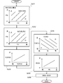
- FIG. 6 is a time chart illustrating changes in the blow-by gas retention amount BGR and the like when the delay process for starting the fuel cut shown in the flowchart of FIG. 5 is performed.
- the internal combustion engine 1 near time t21, the internal combustion engine 1 is operated with a high load in which a large amount of blow-by gas is generated, that is, a high load in which the intake pressure becomes near atmospheric pressure, and at time t22 due to deceleration from the high load operation.
- the fuel cut start condition is satisfied.
- the control device 13 does not start the fuel cut from the time when the fuel cut start condition is satisfied, but sets the delay time DTFC based on the blow-by gas retention amount BGR, and when the fuel cut start condition is satisfied.
- the fuel cut is started at the time t23 when the delay time DTFC has elapsed from. That is, from the time t22 to the time t23 when the fuel cut start condition is satisfied, the fuel cut condition is satisfied, but the control device 13 continues the fuel injection by the fuel injection device 5.
- Blow-by gas combustion processing is performed in the fuel injection continuation section (in other words, within the delay time DTFC) from time t22 to time t23 when the fuel cut start condition is satisfied, and the control device 13 controls the blow-by gas retention amount.
- the fuel cut is started at time t23, which is the time when the BGR drops to a predetermined amount.
- the delay time DTFC is set based on the time required to reduce the blow-by gas retention amount BGR when the fuel cut start condition is satisfied to a predetermined amount in the combustion process.
- control device 13 Since the control device 13 starts the fuel cut after the blow-by gas retention amount BGR is less than when the fuel cut start condition is satisfied, the amount of blow-by gas flowing into the combustion chamber 10 during the fuel cut is reduced, and the fuel cut Compared with the case where the fuel cut is started when the start condition is satisfied, the formation of particulate matter can be suppressed.
- the control device 13 When the control device 13 performs the fuel cut start delay process shown in the flowchart of FIG. 5, the control device 13 minimizes the fuel injection amount by the fuel injection device 5 within the delay time DTFC from the time when the fuel cut start condition is satisfied.
- the injection amount can be set (see step S305).
- the minimum injection amount is the lower limit of the fuel amount range that can be injected by one injection, and the fuel amount range that can be injected by one injection is the amount of fuel that is proportional to the injection time of the fuel injection device 5. Is the range to be injected. That is, the minimum injection amount is the minimum value of the fuel injection amount that can be controlled by the control device 13.
- the control device 13 sets the fuel injection amount by the fuel injection device 5 to the minimum injection amount within the delay time DTFC from the time when the fuel cut start condition is satisfied, and continues the fuel injection.
- the fuel injection amount by the fuel injection device 5 is set to the minimum injection amount while the start of the fuel cut is delayed, so that the increase in fuel consumption due to the delay in the start of the fuel cut is minimized. Therefore, deterioration of fuel efficiency can be suppressed.
- FIG. 7 is a time chart illustrating changes in the fuel injection amount when the fuel injection amount by the fuel injection device 5 is set to the minimum injection amount in the delay time DTFC.
- the control device 13 delays the start of the fuel cut by the delay time DTFC from the establishment of the fuel cut start condition at the time t31, and starts the fuel cut at the time t32 when the delay time DTFC has elapsed.
- the control device 13 sets the fuel injection amount by the fuel injection device 5 to the minimum injection amount, and from the time t32, the fuel injection amount by the fuel injection device 5 is set. Set to zero and shift to the fuel cut state.
- the control device 13 does not operate the PCV valve 44 in the valve opening direction after the delay time DTPCV has elapsed. From the time when fuel injection is restarted, the PCV valve 44 can be operated little by little in the valve opening direction at an operation speed corresponding to the blow-by gas retention amount BGR. Further, in the valve closing control of the PCV valve 44 during the fuel cut, the first blow-by gas recirculation passage 43 is not completely shielded, and an opening to the extent that a predetermined leakage flow rate is generated can be provided.
- the direction of opening the PCV valve 44 is determined depending on the condition for restarting fuel injection from the fuel cut, that is, whether the fuel injection is restarted by lowering the engine speed or the fuel injection is restarted by depressing the accelerator pedal.
- the response delay of the operation can be set individually.
- the control device 13 moves the PCV valve 44 in the valve opening direction based on the emission amount of the particulate matter detected by the sensor. It is possible to modify the operation response delay setting and the fuel cut start delay time setting.
Landscapes
- Engineering & Computer Science (AREA)
- Mechanical Engineering (AREA)
- General Engineering & Computer Science (AREA)
- Chemical & Material Sciences (AREA)
- Combustion & Propulsion (AREA)
- Lubrication Details And Ventilation Of Internal Combustion Engines (AREA)
- Electrical Control Of Air Or Fuel Supplied To Internal-Combustion Engine (AREA)
Priority Applications (1)
| Application Number | Priority Date | Filing Date | Title |
|---|---|---|---|
| JP2021552399A JP7212798B2 (ja) | 2019-10-18 | 2020-10-13 | 内燃機関の制御装置及び制御方法 |
Applications Claiming Priority (2)
| Application Number | Priority Date | Filing Date | Title |
|---|---|---|---|
| JP2019-190669 | 2019-10-18 | ||
| JP2019190669 | 2019-10-18 |
Publications (1)
| Publication Number | Publication Date |
|---|---|
| WO2021075432A1 true WO2021075432A1 (ja) | 2021-04-22 |
Family
ID=75538493
Family Applications (1)
| Application Number | Title | Priority Date | Filing Date |
|---|---|---|---|
| PCT/JP2020/038652 Ceased WO2021075432A1 (ja) | 2019-10-18 | 2020-10-13 | 内燃機関の制御装置及び制御方法 |
Country Status (2)
| Country | Link |
|---|---|
| JP (1) | JP7212798B2 (https=) |
| WO (1) | WO2021075432A1 (https=) |
Citations (6)
| Publication number | Priority date | Publication date | Assignee | Title |
|---|---|---|---|---|
| JPS55163456U (https=) * | 1979-05-11 | 1980-11-25 | ||
| JPH01179112U (https=) * | 1988-06-10 | 1989-12-22 | ||
| JP2010163895A (ja) * | 2009-01-13 | 2010-07-29 | Toyota Motor Corp | 内燃機関の吸気制御装置 |
| JP2013164053A (ja) * | 2012-02-13 | 2013-08-22 | Toyota Motor Corp | 内燃機関の制御装置 |
| JP2015040543A (ja) * | 2013-08-23 | 2015-03-02 | ダイハツ工業株式会社 | 内燃機関の制御装置 |
| JP2015158186A (ja) * | 2014-02-25 | 2015-09-03 | スズキ株式会社 | エンジンの制御装置 |
-
2020
- 2020-10-13 JP JP2021552399A patent/JP7212798B2/ja active Active
- 2020-10-13 WO PCT/JP2020/038652 patent/WO2021075432A1/ja not_active Ceased
Patent Citations (6)
| Publication number | Priority date | Publication date | Assignee | Title |
|---|---|---|---|---|
| JPS55163456U (https=) * | 1979-05-11 | 1980-11-25 | ||
| JPH01179112U (https=) * | 1988-06-10 | 1989-12-22 | ||
| JP2010163895A (ja) * | 2009-01-13 | 2010-07-29 | Toyota Motor Corp | 内燃機関の吸気制御装置 |
| JP2013164053A (ja) * | 2012-02-13 | 2013-08-22 | Toyota Motor Corp | 内燃機関の制御装置 |
| JP2015040543A (ja) * | 2013-08-23 | 2015-03-02 | ダイハツ工業株式会社 | 内燃機関の制御装置 |
| JP2015158186A (ja) * | 2014-02-25 | 2015-09-03 | スズキ株式会社 | エンジンの制御装置 |
Also Published As
| Publication number | Publication date |
|---|---|
| JPWO2021075432A1 (https=) | 2021-04-22 |
| JP7212798B2 (ja) | 2023-01-25 |
Similar Documents
| Publication | Publication Date | Title |
|---|---|---|
| US7464674B2 (en) | Induction air acoustics management for internal combustion engine | |
| US7900611B2 (en) | Apparatus and method for treating blow-by gas for internal combustion engine | |
| JP4962622B2 (ja) | 車両の制御装置 | |
| WO2012173177A1 (ja) | エンジンの制御装置 | |
| CN110821607A (zh) | 内燃机的控制装置及控制方法以及记录介质 | |
| JP4655002B2 (ja) | 内燃機関の制御装置 | |
| US20200224623A1 (en) | Internal combustion engine control device and control method | |
| US5899192A (en) | Fuel supply control system for internal combustion engines | |
| JP4348705B2 (ja) | 内燃機関の燃料噴射制御装置 | |
| WO2019058705A1 (ja) | エンジンシステム | |
| JP2009121298A (ja) | 内燃機関用スロットルバルブの凍結防止制御方法 | |
| WO2021075432A1 (ja) | 内燃機関の制御装置及び制御方法 | |
| JPS6052301B2 (ja) | 空燃比制御装置 | |
| US11028798B2 (en) | Internal-combustion-engine control device and control method | |
| US11002213B2 (en) | Internal combustion engine control device and control method | |
| JP7145018B2 (ja) | 内燃機関の燃料噴射制御装置 | |
| JPH0733797B2 (ja) | アイドル回転数制御方法 | |
| JP2006329003A (ja) | 内燃機関の二次空気供給装置 | |
| JPS61247868A (ja) | エンジンの点火時期制御装置 | |
| JP2009228529A (ja) | 内燃機関のブローバイガス処理装置 | |
| JP2009185664A (ja) | 内燃機関のブローバイガス処理装置 | |
| JP2020045814A (ja) | 内燃機関の燃料噴射制御装置 | |
| JP2005069045A (ja) | 内燃機関の燃料噴射制御装置 | |
| JPH041437A (ja) | 内燃機関の燃料噴射量制御装置 | |
| JP2009215907A (ja) | 内燃機関の制御装置 |
Legal Events
| Date | Code | Title | Description |
|---|---|---|---|
| 121 | Ep: the epo has been informed by wipo that ep was designated in this application |
Ref document number: 20876235 Country of ref document: EP Kind code of ref document: A1 |
|
| ENP | Entry into the national phase |
Ref document number: 2021552399 Country of ref document: JP Kind code of ref document: A |
|
| NENP | Non-entry into the national phase |
Ref country code: DE |
|
| 122 | Ep: pct application non-entry in european phase |
Ref document number: 20876235 Country of ref document: EP Kind code of ref document: A1 |