WO2021065424A1 - Rotor, moteur de traction et procédé de fabrication de rotor - Google Patents
Rotor, moteur de traction et procédé de fabrication de rotor Download PDFInfo
- Publication number
- WO2021065424A1 WO2021065424A1 PCT/JP2020/034537 JP2020034537W WO2021065424A1 WO 2021065424 A1 WO2021065424 A1 WO 2021065424A1 JP 2020034537 W JP2020034537 W JP 2020034537W WO 2021065424 A1 WO2021065424 A1 WO 2021065424A1
- Authority
- WO
- WIPO (PCT)
- Prior art keywords
- axial direction
- rotor
- core
- resin
- core block
- Prior art date
Links
Images


Classifications
-
- H—ELECTRICITY
- H02—GENERATION; CONVERSION OR DISTRIBUTION OF ELECTRIC POWER
- H02K—DYNAMO-ELECTRIC MACHINES
- H02K15/00—Methods or apparatus specially adapted for manufacturing, assembling, maintaining or repairing of dynamo-electric machines
- H02K15/12—Impregnating, heating or drying of windings, stators, rotors or machines
-
- H—ELECTRICITY
- H02—GENERATION; CONVERSION OR DISTRIBUTION OF ELECTRIC POWER
- H02K—DYNAMO-ELECTRIC MACHINES
- H02K1/00—Details of the magnetic circuit
- H02K1/06—Details of the magnetic circuit characterised by the shape, form or construction
- H02K1/22—Rotating parts of the magnetic circuit
- H02K1/27—Rotor cores with permanent magnets
- H02K1/2706—Inner rotors
- H02K1/272—Inner rotors the magnetisation axis of the magnets being perpendicular to the rotor axis
- H02K1/274—Inner rotors the magnetisation axis of the magnets being perpendicular to the rotor axis the rotor consisting of two or more circumferentially positioned magnets
- H02K1/2753—Inner rotors the magnetisation axis of the magnets being perpendicular to the rotor axis the rotor consisting of two or more circumferentially positioned magnets the rotor consisting of magnets or groups of magnets arranged with alternating polarity
- H02K1/276—Magnets embedded in the magnetic core, e.g. interior permanent magnets [IPM]
- H02K1/2766—Magnets embedded in the magnetic core, e.g. interior permanent magnets [IPM] having a flux concentration effect
-
- H—ELECTRICITY
- H02—GENERATION; CONVERSION OR DISTRIBUTION OF ELECTRIC POWER
- H02K—DYNAMO-ELECTRIC MACHINES
- H02K1/00—Details of the magnetic circuit
- H02K1/06—Details of the magnetic circuit characterised by the shape, form or construction
- H02K1/22—Rotating parts of the magnetic circuit
- H02K1/28—Means for mounting or fastening rotating magnetic parts on to, or to, the rotor structures
-
- H—ELECTRICITY
- H02—GENERATION; CONVERSION OR DISTRIBUTION OF ELECTRIC POWER
- H02K—DYNAMO-ELECTRIC MACHINES
- H02K15/00—Methods or apparatus specially adapted for manufacturing, assembling, maintaining or repairing of dynamo-electric machines
- H02K15/02—Methods or apparatus specially adapted for manufacturing, assembling, maintaining or repairing of dynamo-electric machines of stator or rotor bodies
- H02K15/03—Methods or apparatus specially adapted for manufacturing, assembling, maintaining or repairing of dynamo-electric machines of stator or rotor bodies having permanent magnets
-
- Y—GENERAL TAGGING OF NEW TECHNOLOGICAL DEVELOPMENTS; GENERAL TAGGING OF CROSS-SECTIONAL TECHNOLOGIES SPANNING OVER SEVERAL SECTIONS OF THE IPC; TECHNICAL SUBJECTS COVERED BY FORMER USPC CROSS-REFERENCE ART COLLECTIONS [XRACs] AND DIGESTS
- Y02—TECHNOLOGIES OR APPLICATIONS FOR MITIGATION OR ADAPTATION AGAINST CLIMATE CHANGE
- Y02T—CLIMATE CHANGE MITIGATION TECHNOLOGIES RELATED TO TRANSPORTATION
- Y02T10/00—Road transport of goods or passengers
- Y02T10/60—Other road transportation technologies with climate change mitigation effect
- Y02T10/64—Electric machine technologies in electromobility
Definitions
- the present invention relates to a rotor.
- the present application claims priority based on Japanese Patent Application No. 2019-179309 filed in Japan on September 30, 2019, the contents of which are incorporated herein by reference.
- Japanese Unexamined Patent Publication No. 2018-7843 describes a rotor core which is formed by laminating a plurality of electromagnetic steel sheets in the axial direction and in which a plurality of permanent magnets are embedded.
- the rotor core has a step skew configuration in which the positions of the permanent magnets are gradually shifted in the circumferential direction with respect to the axial direction.
- Japanese Patent Application Laid-Open No. 2018-7483 discloses an injection step of injecting an adhesive into the first-stage magnet insertion hole, an insertion step of inserting a permanent magnet into the magnet insertion hole, and a magnet insertion.
- the filling steps of filling the holes with the adhesive are performed in sequence.
- an injection step is performed in the magnet insertion holes of the second stage.
- Insertion step and filling step are performed.
- An object of the present invention is to provide a technique for improving the production efficiency of a rotor having a skew structure.
- the first aspect is a rotor that rotates about a rotation axis, which is composed of a plurality of steel plates laminated in the axial direction of the rotation axis and has a plurality of insertion holes arranged in the circumferential direction.
- a core laminate formed by stacking blocks in a plurality of stages in the axial direction, a plurality of magnets located inside the plurality of insertion holes, and the magnets fixed to the inside of the plurality of insertion holes.
- the core blocks provided with a plurality of resin members and adjacent to each other in the axial direction are located at different angles with respect to the rotation axis, and the insertion holes of the core blocks adjacent to each other in the axial direction are axial to each other.
- the resin member is connected to a filling portion located in the insertion hole, a first gate portion located on one side of the filling portion in the axial direction, and a second gate portion located on the other side of the filling portion in the axial direction. It is provided with a gate portion.
- the rotor having the above configuration by filling the insertion holes communicating in the axial direction with the resin at one time, the number of work steps can be reduced as compared with the case where the resin is filled for each core block. Further, when the fluid resin is injected into the insertion hole through the inflow port of the mold corresponding to the first gate portion, even if the resin moves partially in the insertion hole, the resin that has moved first. Can flow out from the insertion hole of the core block on the other side in the axial direction through the outlet of the mold corresponding to the second gate portion. As a result, the fluid resin can be spread over the entire inside of the insertion hole, so that it is possible to suppress poor filling of the resin in the insertion hole. Therefore, the productivity of the rotor can be improved.
- FIG. 1 is a perspective view of the rotor according to the first embodiment.
- FIG. 2 is a perspective view showing one side of the resin member according to the first embodiment in the axial direction.
- FIG. 3 is a perspective view showing one side of the resin member according to the first embodiment in the axial direction.
- FIG. 4 is a flow chart showing an example of a rotor manufacturing method according to the first embodiment.
- FIG. 5 is a perspective view showing the mold of the first embodiment.
- FIG. 6 is a vertical cross-sectional view of the traction motor of the second embodiment.
- FIG. 7 is a perspective view showing one side of the rotor according to the second embodiment in the axial direction.
- FIG. 8 is a perspective view showing the other side in the axial direction of the rotor according to the second embodiment.
- FIG. 1 is a perspective view of the rotor according to the first embodiment.
- FIG. 2 is a perspective view showing one side of the resin member according to the first embodiment in the axial direction.
- FIG. 9 is a perspective view showing one side of the core laminate according to the second embodiment in the axial direction.
- FIG. 10 is a perspective view showing the other side in the axial direction of the core laminate according to the second embodiment.
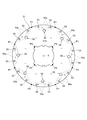
- FIG. 11 is a plan view showing the first core block on one side in the axial direction.
- FIG. 12 is a plan view showing the first end plate on one side in the axial direction.
- FIG. 13 is a plan view showing the second end plate on the other side in the axial direction.
- FIG. 14 is a perspective view of the resin member of the second embodiment.
- FIG. 15 is a flow chart of a rotor manufacturing method according to the second embodiment.
- FIG. 16 is a perspective view showing an example of a mold.
- FIG. 17 is a diagram showing the inner surface of the mold on the other side.
- FIG. 18 is a diagram showing a resin member formed in the mold.
- the direction parallel to the rotation axis of the rotor is referred to as "axial direction”
- the direction orthogonal to the axial direction is referred to as “diameter direction”
- the direction along the arc centered on the rotation axis is referred to as “circumferential direction”.
- the direction approaching the rotation axis is the radial inward direction
- the direction away from the rotation axis is the radial outer direction.
- FIG. 1 is a perspective view of the rotor 3A according to the first embodiment.
- the rotor 3A rotates about the rotation shaft 9A.
- the rotor 3A includes a core laminate 40A.
- the core laminated body 40A is configured by laminating a first core block 41A and a second core block 42A in a plurality of stages in the axial direction.
- Each core block 41A, 42A is formed by laminating a plurality of steel plates.
- the first core block 41A is located at one end in the axial direction
- the second core block 42A is located at the other end in the axial direction.
- the first core block 41A has a plurality of insertion holes 43A arranged in the circumferential direction.
- the second core block 42A also has a plurality of insertion holes 43B arranged in the circumferential direction.
- a magnet 60A is located inside each of the insertion holes 43A and 43B. The magnet 60A is fixed by the resin member 70A inside the insertion holes 43A and 43B.
- the core blocks 41A and 42A are adjacent to each other in the axial direction, and are positioned so as to be offset from each other with respect to the rotation axis 9A. That is, the core laminate 40A has a skew structure.
- the insertion holes 43A and 43B communicate with each other in the axial direction. "Communication” here means a state in which fluids are connected so that they can flow.
- FIG. 2 is a perspective view showing one side of the resin member 70A according to the first embodiment in the axial direction.
- FIG. 3 is a perspective view showing the other side of the resin member 70A according to the first embodiment in the axial direction.
- the resin member 70A includes a filling portion 71A located in the insertion holes 43A and 43B, a first gate portion 73A located on one side in the axial direction of the filling portion 71A, and a filling portion 71A. It has a second gate portion 75A located on the other side in the axial direction.
- FIG. 4 is a flow chart showing an example of a method for manufacturing the rotor 3A according to the first embodiment.
- a preparatory step S1A for preparing the core laminate 40A is performed.
- core blocks 41A and 42A are produced by laminating a plurality of steel plates.
- the first core block 41A is laminated on one side of the second core block 42A in the axial direction while being displaced in the circumferential direction with respect to the second core block 42A about the rotation axis 9A.
- a magnet 60A is inserted into the insertion holes 43A and 43B of the core blocks 41A and 42A.
- the arrangement step S2A for arranging the core laminate 40A in the mold 80A is performed.
- FIG. 5 is a perspective view showing the mold 80A of the first embodiment.
- the mold 80 has a one-side mold 81A and a other-side mold 82A.
- the one-side mold 81A and the other-side mold 82A have a concave inner surface corresponding to the outer shape of the core laminate 40A.
- the one-side mold 81A is provided with a plurality of (8 in this example) injection ports 83A. Each injection port 83A communicates with the insertion hole 43A of the first core block 41A.
- a plurality of concave outlets (8 in this example) 851A are provided on the inner surface of the other side mold 82A, and the outlet 851A is a resin provided inside the other side mold 82A. It communicates with the reservoir 85A.
- each outlet 851A is communicated with the insertion hole 43B of the second core block 42A.
- the injection step S3A is performed after the placement step S2A.
- the injection step S3A by injecting a fluid resin into the injection port 83A of the mold 80A shown in FIG. 5, the resin is injected into each insertion hole 43A and each insertion hole 43B communicating with each insertion hole 43A.
- the filling step S4A is performed.
- the fluid resin injected into the mold 80A by the injection step S3A is filled into the insertion holes 43A and 43B while flowing out from the insertion hole 43B to the resin reservoir 85A through the outlet 851A. ..
- the resin member 70A is formed by curing the resin filled in the insertion holes 43A and 43B in the filling step S4A.
- the first gate portion 73A is a part of a convex portion formed by flowing into the insertion hole 43A from the injection port 83A.
- the second gate portion 75A is a part of a convex portion formed by the resin flowing out to the outlet 851A and the resin pool portion 85A.
- the number of steps is smaller than that in the case where the resin is filled in each of the core blocks 41A and 42A. can do.
- the fluid resin is injected from the injection port 83A of the mold 80A, even if the resin moves partially in the insertion holes 43A and 43B, the previously moved resin is discharged from the insertion hole 43B. It can flow out to the resin reservoir 85A via the 851A.
- the fluid resin can be spread over the entire inside of the insertion holes 43A and 43B, so that it is possible to suppress poor filling of the resin in the insertion holes 43A and 43B. Therefore, the productivity of the rotor 3A can be improved. Further, the position of the magnet 60A in the insertion holes 43A and 43B can be stabilized.
- FIG. 6 is a vertical cross-sectional view of the traction motor 1 of the second embodiment.
- the traction motor 1 is a device mounted on a vehicle such as an electric vehicle or a plug-in hybrid vehicle and outputs a driving force for traveling of the vehicle.
- the traction motor 1 includes a motor 11, a gear 13, and an inverter 15.
- the motor 11 has a stationary portion 2 and a rotor 3.
- the stationary portion 2 rotatably supports the rotor 3.
- the gear 13 is connected to the motor 11.
- the inverter 15 is electrically connected to the motor 11.
- the inverter 15 is a device that converts direct current into alternating current, and supplies the drive current obtained by the conversion to the motor 11.
- the stationary portion 2 has a housing 21, a lid portion 22, a stator 23, a first bearing portion 24, and a second bearing portion 25.
- the housing 21 is a bottomed substantially cylindrical housing that internally houses the stator 23, the first bearing portion 24, the rotor 3, and the shaft 30.
- a recess 211 for holding the first bearing portion 24 is provided in the center of the bottom portion of the housing 21.
- the lid portion 22 is a plate-shaped member that closes the opening on one side of the housing 21 in the axial direction.
- a circular hole 221 for holding the second bearing portion 25 is provided in the center of the lid portion 22.
- the stator 23 generates magnetic flux according to the drive current.
- the stator 23 has a stator core 26 and a coil 27.
- the stator core 26 is made of a laminated steel plate in which a plurality of steel plates are laminated in the axial direction.
- the stator core 26 has an annular core back 261 and a plurality of tooth portions 262 protruding inward in the radial direction from the core back 261.
- the core back 261 is fixed to the inner peripheral surface of the side wall of the housing 21.
- the coil 27 is composed of a conducting wire wound around each tooth portion 262 of the stator core 26.
- the first bearing portion 24 and the second bearing portion 25 are mechanisms that rotatably support the shaft 30 connected to the through hole 3H of the rotor 3.
- ball bearings that relatively rotate the outer ring and the inner ring via a sphere are used.
- bearings of other types such as slide bearings and fluid bearings may be used.
- the outer ring 241 of the first bearing portion 24 is fixed to the recess 211 of the housing 21. Further, the outer ring 251 of the second bearing portion 25 is fixed to the edge of the circular hole 221 of the lid portion 22. On the other hand, the inner rings 242 and 252 of the first bearing portion 24 and the second bearing portion 25 are fixed to the shaft 30. Therefore, the shaft 30 is rotatably supported by the housing 21 and the lid 22.
- the shaft 30 is a substantially columnar member extending in the axial direction along the rotation shaft 9.
- the shaft 30 rotates about a rotating shaft 9 while being supported by the first bearing portion 24 and the second bearing portion 25 described above.
- the shaft 30 has a head portion 301 protruding from the lid portion 22 on one side in the axial direction.
- the head 301 is connected to a driving object of an automobile via a gear 13 which is a power transmission mechanism.
- the rotor 3 rotates together with the shaft 30 inside the stator 23 in the radial direction.
- the rotor 3 has a plurality of magnets 60, as will be described later.
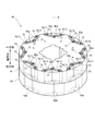
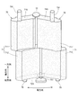
- FIG. 7 is a perspective view showing one side of the rotor 3 according to the second embodiment in the axial direction.
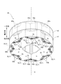
- FIG. 8 is a perspective view showing the other side of the rotor 3 according to the second embodiment in the axial direction.
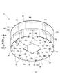
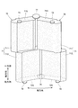
- FIG. 9 is a perspective view showing one side in the axial direction of the core laminated body 40 according to the second embodiment.
- FIG. 10 is a perspective view showing the other side in the axial direction of the core laminated body 40 according to the second embodiment.
- FIG. 11 is a plan view showing the first core block 41 on one side in the axial direction.
- FIG. 12 is a plan view showing the first end plate 51 on one side in the axial direction.
- FIG. 13 is a plan view showing the second end plate 52 on the other side in the axial direction.
- FIG. 14 is a perspective view of the resin member 70 of the second embodiment.
- the rotor 3 has a core laminate 40, a first end plate 51, a second end plate 52, a plurality of magnets 60, and a plurality of resin members 70.
- the core laminate 40 is formed by laminating two first core blocks 41 and a second core block 42 in the axial direction.
- Each of the core blocks 41 and 42 is composed of a plurality of substantially annular steel plates laminated in the axial direction.
- the core blocks 41 and 42 have the same shape and size.
- the core blocks 41 and 42 are adjacent to each other in the axial direction, and are positioned so as to be offset from each other in the circumferential direction with the rotation axis 9 as the center. That is, the core laminate 40 has a so-called skew structure.
- the deviation angle (skew angle) of the second core block 42 with respect to the first core block 41 is, for example, 3.25 °.
- the first core block 41 has 16 insertion holes 43a arranged in the circumferential direction. More specifically, the first core block 41 has eight pairs of insertion holes 43a, 43a that are close to each other in the circumferential direction at equal intervals in the circumferential direction. The pair of insertion holes 43a, 43a are adjacent to each other at intervals in the circumferential direction when viewed from the axial direction, and form a V-shape that separates from each other in the circumferential direction toward the outside in the radial direction.
- the second core block 42 also has 16 insertion holes 43b arranged in the circumferential direction. That is, the second core block 42 has eight pairs of insertion holes 43b and 43b that are close to each other in the circumferential direction at equal intervals in the circumferential direction.
- the pair of insertion holes 43b, 43b also have a V shape when viewed from the axial direction, like the pair of insertion holes 43a, 43a.
- the insertion hole 43b has the same shape and size as the insertion hole 43a.
- the insertion holes 43a and 43b are through holes having a constant opening shape in the axial direction. Each insertion hole 43a communicates with the insertion hole 43b in the axial direction. That is, as shown in FIGS. 7 and 8, the insertion hole 43a and the insertion hole 43b form one continuous continuous hole 43.
- One magnet 60 is arranged in each of the insertion holes 43a and 43b.
- the pair of magnets 60 can be arranged in a V shape. Thereby, the magnetic characteristics of the rotor 3 can be improved.
- magnets 60 are arranged one by one so that the magnetic poles of the surfaces facing outward in the radial direction are the same.
- the magnets 60 arranged in the pair of insertion holes 43a, 43a and the other pair of insertion holes 43a, 43a adjacent to each other in the circumferential direction are arranged so that the magnetic poles of the surfaces facing outward in the radial direction are different.
- the magnet 60 is fixed to the inside of the insertion holes 43a and 43b by the resin member 70 described later.
- the end plates 51 and 52 are the same substantially annular plate-shaped members.
- the first end plate 51 has a plurality of (16 in this example) first through holes 53 and a plurality of (8 in this example) second through holes. It has a third connection hole 55 which is a hole.
- the second end plate 52 also has a plurality of (16 in this example) first through holes 56 and a plurality of (8 in this example) second through holes. It has a second connection hole 54 which is a through hole.
- the plurality of first connection holes 53 are located on the same circumference
- the plurality of third connection holes 55 are located on the same circumference at equal intervals.
- the plurality of fourth connection holes 56 are located on the same circumference
- the second connection holes 54 are located on the same circumference at equal intervals.
- the first end plate 51 is located on one side in the axial direction of the core laminate 40.
- the first end plate 51 faces a plurality of magnets 60 arranged in the insertion holes 43a in the axial direction, and prevents the magnets 60 from falling off from the insertion holes 43a in one axial direction.
- the first connection hole 53 of the first end plate 51 communicates with the insertion hole 43a of the first core block 41. Since the first end plate 51 has the first connection hole 53, the resin member 70 can be filled from one side in the axial direction of the continuous hole 43 after the first end plate 51 is attached to the core laminate 40. is there.
- the second end plate 52 is located on the other side in the axial direction of the core laminate 40.
- the second end plate 52 faces the plurality of magnets 60 arranged in the insertion holes 43b in the axial direction, and prevents the magnets 60 from falling off from the insertion holes 43b in the other direction in the axial direction.
- the second connection hole 54 of the second end plate 52 communicates with the insertion hole 43b of the second core block 42. Since the second end plate 52 has the second connection hole 54, the resin member 70 can flow out from the other side in the axial direction of the continuous hole 43 after the second end plate 52 is attached to the core laminate 40.
- Each of the core blocks 41 and 42 is provided with a pair of insertion holes 43a and 43a and a pair of insertion holes 43b and 43b that are close to each other in the circumferential direction. Therefore, in the rotor 3, as shown in FIG. 14, the pair of resin members 70 are arranged so as to be close to each other in the circumferential direction.
- the resin member 70 has a filling portion 71, a first gate portion 73, and a second gate portion 75.
- the filling portion 71 is located inside the insertion holes 43a and 43b (that is, the continuous holes 43) that communicate with each other in the axial direction.
- the filling portion 71 has a first filling portion 711 located inside the insertion hole 43a and a second filling portion 712 located inside the insertion hole 43b.
- the first gate portion 73 is located on one side in the axial direction of the filling portion 71.
- the first gate portion 73 is a convex portion of the first filling portion 711 that protrudes from the first end surface 71S on one side in the axial direction to one side in the axial direction.
- the first gate portion 73 is a portion provided inside the first connection hole 53.
- the end portion on one side in the axial direction of the first gate portion 73 is located on the other side in the axial direction with respect to the end surface 51S on one side in the axial direction of the first end plate 51. Since the first gate portion 73 does not project axially from the first end plate 51, it is possible to prevent the first gate portion 73 from coming into contact with other members.
- the second gate portion 75 is located on the other side of the filling portion 71 in the axial direction.
- the second gate portion 75 is a convex portion of the second filling portion 712 that protrudes from the second end surface 72S on the other side in the axial direction to the other side in the axial direction.
- the second gate portion 75 is a portion provided in the second connection hole 54.
- the end of the second gate portion 75 on the other side in the axial direction is located on one side in the axial direction with respect to the end surface 52S on the other side in the axial direction of the second end plate 52. Since the second gate portion 75 does not project axially from the second end plate 52, it is possible to prevent the second gate portion 75 from coming into contact with other members.
- the resin member 70 When forming the resin member 70, the resin is injected into the first connection hole 53 of the first end plate 51. Then, the resin enters the insertion hole 43a of the first core block 41 and the insertion hole 43b of the second core block 42 through the first connection hole 53. Further, some resin flows out from the insertion hole 43b through the second connection hole 54.
- the second connection hole 54 As shown in FIG. 13, the second connection hole 54 is arranged at a position where it overlaps both of the pair of insertion holes 43b and 43b in the axial direction. Therefore, as shown in FIG. 14, a pair of filling portions 71, 71 (more specifically, a pair of second gate portions) that are close to each other in the circumferential direction by one second gate portion 75 formed in the second connection hole 54. Filling portions 712,712) are connected.
- the second connection hole 54 in the second end plate 52 is located closer to the rotation shaft 9 than the first connection hole 53 in the first end plate 51. Therefore, the second gate portion 75 located in the second connection hole 54 is located closer to the rotation shaft 9 than the first gate portion 73 provided in the first connection hole 53.
- the resin flows from the outer side in the radial direction to the inner side in the radial direction in the continuous hole 43. Therefore, the magnet 60 can be fixed while being pressed against the radial inner surface of the continuous hole 43, and the magnet 60 can be stably arranged in the continuous hole 43.
- the second gate portion 75 provided on the pair of resin members 70, 70 is located between the pair of first gate portions 73, 73 of each of the pair of resin members 70, 70 in the circumferential direction. To position.
- the third connection hole 55 of the first end plate 51 communicates with a pair of insertion holes 43a, 43a that are close to each other in the circumferential direction. That is, the third connection hole 55 is provided at a position straddling the pair of insertion holes 43a, 43a.
- the third connection hole 55 releases the gas generated from the resin from the insertion hole 43a when the continuous hole 43 is filled with the resin.
- a convex portion 77 is formed on the first end surface 71S of the resin member 70 by the third connection hole 55.
- the pair of resin members 70, 70 (more specifically, the pair of first filling portions 711 and 711) that are close to each other in the circumferential direction are connected by one convex portion 77 provided on one side in the axial direction. ..
- the convex portion 77 located in the third connection hole 55 is located closer to the rotation shaft 9 than the first gate portion 73 located in the first connection hole 53.
- the fourth connection hole 56 of the second end plate 52 communicates with the insertion hole 43b of the second core block 42.
- a convex portion 79 is formed in the resin member 70 by the fourth connection hole 56.
- the convex portion 79 is provided on the second end surface 72S of the filling portion 71.
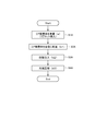
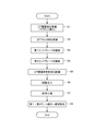
- FIG. 15 is a flow chart of a manufacturing method of the rotor 3 according to the second embodiment.
- a preparatory step S1 for preparing the core laminate 40 is performed.
- the core blocks 41 and 42 adjacent to each other in the axial direction are arranged so as to be offset from each other with respect to the rotation axis 9, and the insertion holes 43a and 43b of the core blocks 41 and 42 adjacent to each other in the axial direction communicate with each other in the axial direction. It is said that it is in a state of being.
- the preparation step S1 includes a magnet insertion step of inserting the magnet 60 into the insertion holes 43a and 43b.
- the third welding step S4 for welding the end plate 52 is performed.
- a laminate having the first end plate 51, the core blocks 41, 42, and the second end plate 52 is formed.
- the welding position is not particularly limited.
- a plurality of locations dispersed in the circumferential direction on the outer peripheral portion of the first end plate 51 (in the illustrated example, the first end plate 51 is welded).
- Welding may be performed at the welding positions P1 (8 locations).
- welding may be performed at a plurality of welding positions (4 locations in the illustrated example) dispersed in the circumferential direction.
- FIG. 16 is a perspective view showing an example of the mold 80.
- FIG. 17 is a diagram showing an inner surface 82S of the other side mold 82.
- the core laminated body 40 is shown by a broken line.
- the second core block 42 and the second end plate 52 are shown by broken lines.
- the mold 80 has a one-sided mold 81 arranged on one side in the axial direction and a other-side mold 82 arranged on the other side in the axial direction.
- the one-side mold 81 and the other-side mold 82 may each be configured by combining a plurality of members.
- the one-side mold 81 is provided with a plurality of (16 in this case) injection ports 83.
- each injection port 83 is communicated with the insertion hole 43a of the first core block 41 via the first connection hole 53 of the first end plate 51.
- a plurality of (here, eight) outlets 851 are provided on the inner surface 82S of the other side mold 82.
- the outflow port 851 communicates with the resin reservoir 85 provided inside the mold 82 on the other side.
- the second connection hole 54 of the second end plate 52 vertically overlaps the outlet 851.
- the resin reservoir 85 is communicated with the insertion hole 43b of the second core block 42 via the outlet 851 and the second connection hole 54.
- the fourth connection hole 56 of the second end plate 52 is closed by the inner surface 82S of the other side mold 82.
- the one-side mold 81 is provided with a plurality of (here, eight) outlets 87.
- the discharge port 87 communicates with the insertion hole 43a of the first core block 41 via the third connection hole 55. It is desirable that the diameter of the discharge port 87 is such that only the gas generated from the resin passes through and the resin does not flow into the discharge port 87. As a result, the resin does not flow out from the discharge port 87, and it is possible to suppress the formation of burrs.
- the diameter of the outlet 87 on the other side in the axial direction is preferably smaller than the diameter of the inlet 83 on the other side in the axial direction.
- an injection step S6 for injecting a fluid resin into the injection port 83 is performed.
- the resin is injected into the 16 injection ports 83 at almost the same time. It is not essential to inject the resin into all the injection ports 83 at the same time.
- a filling step S7 is performed in which the inside of the continuous hole 43 is filled with a fluid resin.
- the gap between the inner peripheral surface of the insertion hole 43a and the magnet 60 and the space between the inner peripheral surface of the insertion hole 43b and the magnet 60 are filled with resin.
- the fluid resin injected into the mold 80 is discharged to the resin reservoir 85 via the outlet 851 provided in the mold 82 on the other side.
- the resin that has moved to the other side in the axial direction first flows out from the continuous hole 43 to the resin reservoir 85 through the outlet 851 of the mold 80. Can be made to. Therefore, the inside of the continuous hole 43 can be satisfactorily filled with resin.
- the pair of insertion holes 43a and 43a and the pair of insertion holes 43b and 43b that are close to each other in the circumferential direction are arranged so as to be displaced in the circumferential direction. Therefore, there is a difference in the shape and size of the overlap between the pair of insertion holes 43a and 43a and the pair of insertion holes 43b and 43b. Due to this difference in overlap, a difference in filling speed may occur between the pair of continuous holes 43.
- the resin having the faster filling rate can flow out from the outflow port 851 to the resin reservoir 85. Therefore, the resin can be satisfactorily distributed in both of the pair of continuous holes 43 and 43.
- the resin moving through the pair of continuous holes 43, 43 can flow out to the resin reservoir 85 through the second connection hole 54 communicating with both of the pair of continuous holes 43, 43. Therefore, the amount of resin flowing out can be reduced as compared with the case where the second connection hole 54 is provided for each continuous hole 43.
- the filling step S7 when gas is generated from the resin injected into the continuous hole 43, the gas is discharged to the outside of the mold 80 from the discharge port 87 communicating with the insertion hole 43a. As a result, it is possible to suppress defective filling of the resin due to filling with gas.
- the resin is cured by cooling, and then the core laminate 40 is taken out from the mold 80. Subsequently, the removal step S8 for removing a part of the first gate portion 73 and the second gate portion 75 from the core laminated body 40 is performed.
- FIG. 18 is a diagram showing a resin member 70 formed in the mold 80.
- the resin member 70 formed in the mold 80 has a first gate portion 731 having a shape corresponding to the injection port 83 and a second gate portion 731 having a shape corresponding to the outlet 851 and the resin pool portion 85. It has a gate portion 751.
- the first gate portion 731 has a portion protruding from the first connection hole 53.
- the first gate portion 73 shown in FIG. 14 is provided by removing the portion of the first gate portion 731 that protrudes from the first connection hole 53.
- the second gate portion 751 shown in FIG. 18 has a portion protruding from the second connection hole 54.
- the second gate portion 75 shown in FIG. 14 is provided by removing the portion of the second gate portion 751 that protrudes from the second connection hole 54.
- the number of steps is larger than that in the case of filling the resin in each of the core blocks 41 and 42. Can be reduced.
- the fluid resin is injected from the injection port 83 of the mold 80, even if the resin moves partially in the continuous hole 43, the resin that has moved earlier is inserted into the outlet 851 from the insertion hole 43b. It can be discharged to the resin reservoir 85 through the resin reservoir 85.
- the fluid resin can be spread over the entire inside of the insertion holes 43a and 43b, so that poor filling of the resin in the insertion holes 43a and 43b can be suppressed. Therefore, the productivity of the rotor 3 can be improved. Further, the position of the magnet 60 in the insertion holes 43a and 43b can be stabilized.
- welding between the core blocks 41 and 42 of the core laminate 40, welding between the core laminate 40 and the first end plate 51, and welding between the core laminate 40 and the second end plate 52 is performed once. Can be done. Thereby, the productivity of the traction motor 1 can be improved.
- the second end plate 52 can be made by inverting the first end plate 51. This eliminates the need to individually manufacture the end plates 51 and 52. Further, by using the end plates 51 and 52 as plate members having the same shape provided with the first through holes (connection holes 53 and 56) and the second through holes (connection holes 55 and 54), the end plates 51 and 52 are formed. Is attached to the core laminate 40, and then the insertion holes 43a and 43b of the core laminate 40 can be filled with resin.
- the core laminate 40 is composed of two core blocks 41 and 42, but one or more core blocks may be provided between these core blocks 41 and 42. That is, the core laminated body 40 may be configured by laminating core blocks in three or more stages.
- each member is connected by other means such as caulking or screwing. May be good.
- the present invention can be used for rotors.
Landscapes
- Engineering & Computer Science (AREA)
- Power Engineering (AREA)
- Manufacturing & Machinery (AREA)
- Permanent Field Magnets Of Synchronous Machinery (AREA)
- Iron Core Of Rotating Electric Machines (AREA)
- Manufacture Of Motors, Generators (AREA)
Abstract
Ce rotor tourne autour d'un axe de rotation. Le rotor est pourvu : d'un empilement de noyaux composé de blocs de noyau empilés en une pluralité d'étages dans la direction axiale de l'axe de rotation, les blocs de noyau étant chacun composé d'une pluralité de feuilles d'acier empilées dans la direction axiale et ayant une pluralité de trous d'introduction agencés dans une direction circonférentielle ; d'une pluralité d'aimants positionnés sur l'intérieur de la pluralité de trous d'introduction ; et d'une pluralité d'éléments de résine fixant les aimants sur l'intérieur de la pluralité de trous d'introduction. Les blocs centraux qui sont adjacents les uns aux autres dans la direction axiale sont positionnés à des angles mutuellement décalés autour du centre de l'axe de rotation. Les trous d'introduction des blocs centraux qui sont adjacents les uns aux autres dans la direction axiale sont en communication les uns avec les autres dans la direction axiale. Les éléments de résine sont chacun pourvus d'une position de partie de remplissage dans les trous d'introduction, d'une première partie de porte positionnée sur un côté de la partie de remplissage dans la direction axiale, et d'une seconde partie de porte positionnée sur l'autre côté de la partie de remplissage dans la direction axiale.
Priority Applications (4)
| Application Number | Priority Date | Filing Date | Title |
|---|---|---|---|
| US17/763,653 US20220345013A1 (en) | 2019-09-30 | 2020-09-11 | Rotor, traction motor, and method for manufacturing rotor |
| JP2021550542A JPWO2021065424A1 (fr) | 2019-09-30 | 2020-09-11 | |
| DE112020004675.3T DE112020004675T5 (de) | 2019-09-30 | 2020-09-11 | Rotor, traktionsmotor und verfahren zum herstellen des rotors |
| CN202080068013.6A CN115836463A (zh) | 2019-09-30 | 2020-09-11 | 转子、牵引电动机及转子的制造方法 |
Applications Claiming Priority (2)
| Application Number | Priority Date | Filing Date | Title |
|---|---|---|---|
| JP2019-179309 | 2019-09-30 | ||
| JP2019179309 | 2019-09-30 |
Publications (1)
| Publication Number | Publication Date |
|---|---|
| WO2021065424A1 true WO2021065424A1 (fr) | 2021-04-08 |
Family
ID=75337398
Family Applications (1)
| Application Number | Title | Priority Date | Filing Date |
|---|---|---|---|
| PCT/JP2020/034537 WO2021065424A1 (fr) | 2019-09-30 | 2020-09-11 | Rotor, moteur de traction et procédé de fabrication de rotor |
Country Status (5)
| Country | Link |
|---|---|
| US (1) | US20220345013A1 (fr) |
| JP (1) | JPWO2021065424A1 (fr) |
| CN (1) | CN115836463A (fr) |
| DE (1) | DE112020004675T5 (fr) |
| WO (1) | WO2021065424A1 (fr) |
Cited By (1)
| Publication number | Priority date | Publication date | Assignee | Title |
|---|---|---|---|---|
| CN113765312A (zh) * | 2021-09-28 | 2021-12-07 | 安徽威灵汽车部件有限公司 | 转子压装方法、转子、电动助力转向电机及车辆 |
Citations (5)
| Publication number | Priority date | Publication date | Assignee | Title |
|---|---|---|---|---|
| JP2007110880A (ja) * | 2005-10-17 | 2007-04-26 | Mitsui High Tec Inc | 積層鉄心及びその製造方法 |
| JP2012075296A (ja) * | 2010-09-30 | 2012-04-12 | Hitachi Automotive Systems Ltd | 回転電機、および回転電機の固定子コア製造方法 |
| JP2013070505A (ja) * | 2011-09-22 | 2013-04-18 | Nissan Motor Co Ltd | 回転子 |
| JP2015186325A (ja) * | 2014-03-24 | 2015-10-22 | セイコーエプソン株式会社 | ローター、モーター、及びロボット |
| WO2019027217A1 (fr) * | 2017-08-03 | 2019-02-07 | 엘지이노텍 주식회사 | Moteur |
Family Cites Families (2)
| Publication number | Priority date | Publication date | Assignee | Title |
|---|---|---|---|---|
| JP6615708B2 (ja) | 2016-07-06 | 2019-12-04 | 日立オートモティブシステムズ株式会社 | 回転電機の製造方法 |
| JP7042138B2 (ja) | 2018-03-30 | 2022-03-25 | 日立Astemo株式会社 | 処理装置 |
-
2020
- 2020-09-11 US US17/763,653 patent/US20220345013A1/en active Pending
- 2020-09-11 CN CN202080068013.6A patent/CN115836463A/zh active Pending
- 2020-09-11 DE DE112020004675.3T patent/DE112020004675T5/de active Pending
- 2020-09-11 WO PCT/JP2020/034537 patent/WO2021065424A1/fr active Application Filing
- 2020-09-11 JP JP2021550542A patent/JPWO2021065424A1/ja active Pending
Patent Citations (5)
| Publication number | Priority date | Publication date | Assignee | Title |
|---|---|---|---|---|
| JP2007110880A (ja) * | 2005-10-17 | 2007-04-26 | Mitsui High Tec Inc | 積層鉄心及びその製造方法 |
| JP2012075296A (ja) * | 2010-09-30 | 2012-04-12 | Hitachi Automotive Systems Ltd | 回転電機、および回転電機の固定子コア製造方法 |
| JP2013070505A (ja) * | 2011-09-22 | 2013-04-18 | Nissan Motor Co Ltd | 回転子 |
| JP2015186325A (ja) * | 2014-03-24 | 2015-10-22 | セイコーエプソン株式会社 | ローター、モーター、及びロボット |
| WO2019027217A1 (fr) * | 2017-08-03 | 2019-02-07 | 엘지이노텍 주식회사 | Moteur |
Cited By (2)
| Publication number | Priority date | Publication date | Assignee | Title |
|---|---|---|---|---|
| CN113765312A (zh) * | 2021-09-28 | 2021-12-07 | 安徽威灵汽车部件有限公司 | 转子压装方法、转子、电动助力转向电机及车辆 |
| CN113765312B (zh) * | 2021-09-28 | 2022-08-02 | 安徽威灵汽车部件有限公司 | 转子压装方法、转子、电动助力转向电机及车辆 |
Also Published As
| Publication number | Publication date |
|---|---|
| US20220345013A1 (en) | 2022-10-27 |
| CN115836463A (zh) | 2023-03-21 |
| JPWO2021065424A1 (fr) | 2021-04-08 |
| DE112020004675T5 (de) | 2022-06-15 |
Similar Documents
| Publication | Publication Date | Title |
|---|---|---|
| US10498202B2 (en) | Manufacturing method for rotor for rotary electric machine | |
| US9419481B2 (en) | Rotary electric machine | |
| JP6510195B2 (ja) | モータ及びその製造方法 | |
| JP4715280B2 (ja) | 永久磁石埋め込み型モータ、ポンプ装置、及び永久磁石埋め込み型モータの製造方法 | |
| US8278794B2 (en) | Axial gap type motor and method of manufacturing rotor of motor | |
| TWI596868B (zh) | 永久磁鐵式馬達及永久磁鐵式馬達之製造方法 | |
| WO2012086227A1 (fr) | Rotateur | |
| US20130334910A1 (en) | Rotor for electric rotating machine and method of manufacturing the same | |
| WO2008093622A1 (fr) | Rotor et machine électrique rotative dotée de celui-ci | |
| JP2019068701A (ja) | 回転電機ロータ及びその製造方法 | |
| CN109964388B (zh) | 旋转电机用转子以及旋转电机用转子的制造方法 | |
| JP2008022587A (ja) | Ipmロータ、ipmロータの製造方法およびipmロータの製造装置 | |
| JP6525331B2 (ja) | 回転電機、および回転電機のロータの製造方法 | |
| US10978924B2 (en) | Rotor of electrical rotating machine | |
| JP2014121202A (ja) | 埋込磁石型同期電動機の回転子および埋込磁石型同期電動機 | |
| JP7115912B2 (ja) | ロータの製造方法 | |
| JP2011182552A (ja) | ロータコアおよび回転電機用コア | |
| JP2018088748A (ja) | ロータ端板及び埋込磁石型同期回転電機 | |
| WO2021065424A1 (fr) | Rotor, moteur de traction et procédé de fabrication de rotor | |
| JP2015053831A (ja) | 回転電機のロータ | |
| JP2007202363A (ja) | 回転電機 | |
| JP6956488B2 (ja) | 回転子およびリラクタンス回転電機 | |
| TW201409901A (zh) | 罐構造之電動馬達中的經分割之定子鐵芯零件及使用該零件之定子鐵芯與電動馬達 | |
| JP2009296841A (ja) | 回転電機 | |
| JP7331372B2 (ja) | 回転電機用ロータ |
Legal Events
| Date | Code | Title | Description |
|---|---|---|---|
| 121 | Ep: the epo has been informed by wipo that ep was designated in this application |
Ref document number: 20871408 Country of ref document: EP Kind code of ref document: A1 |
|
| ENP | Entry into the national phase |
Ref document number: 2021550542 Country of ref document: JP Kind code of ref document: A |
|
| 122 | Ep: pct application non-entry in european phase |
Ref document number: 20871408 Country of ref document: EP Kind code of ref document: A1 |