WO2021065424A1 - Rotor, traction motor, and method for manufacturing rotor - Google Patents
Rotor, traction motor, and method for manufacturing rotor Download PDFInfo
- Publication number
- WO2021065424A1 WO2021065424A1 PCT/JP2020/034537 JP2020034537W WO2021065424A1 WO 2021065424 A1 WO2021065424 A1 WO 2021065424A1 JP 2020034537 W JP2020034537 W JP 2020034537W WO 2021065424 A1 WO2021065424 A1 WO 2021065424A1
- Authority
- WO
- WIPO (PCT)
- Prior art keywords
- axial direction
- rotor
- core
- resin
- core block
- Prior art date
Links
Images


Classifications
-
- H—ELECTRICITY
- H02—GENERATION; CONVERSION OR DISTRIBUTION OF ELECTRIC POWER
- H02K—DYNAMO-ELECTRIC MACHINES
- H02K15/00—Methods or apparatus specially adapted for manufacturing, assembling, maintaining or repairing of dynamo-electric machines
- H02K15/12—Impregnating, heating or drying of windings, stators, rotors or machines
-
- H—ELECTRICITY
- H02—GENERATION; CONVERSION OR DISTRIBUTION OF ELECTRIC POWER
- H02K—DYNAMO-ELECTRIC MACHINES
- H02K1/00—Details of the magnetic circuit
- H02K1/06—Details of the magnetic circuit characterised by the shape, form or construction
- H02K1/22—Rotating parts of the magnetic circuit
- H02K1/27—Rotor cores with permanent magnets
- H02K1/2706—Inner rotors
- H02K1/272—Inner rotors the magnetisation axis of the magnets being perpendicular to the rotor axis
- H02K1/274—Inner rotors the magnetisation axis of the magnets being perpendicular to the rotor axis the rotor consisting of two or more circumferentially positioned magnets
- H02K1/2753—Inner rotors the magnetisation axis of the magnets being perpendicular to the rotor axis the rotor consisting of two or more circumferentially positioned magnets the rotor consisting of magnets or groups of magnets arranged with alternating polarity
- H02K1/276—Magnets embedded in the magnetic core, e.g. interior permanent magnets [IPM]
- H02K1/2766—Magnets embedded in the magnetic core, e.g. interior permanent magnets [IPM] having a flux concentration effect
-
- H—ELECTRICITY
- H02—GENERATION; CONVERSION OR DISTRIBUTION OF ELECTRIC POWER
- H02K—DYNAMO-ELECTRIC MACHINES
- H02K1/00—Details of the magnetic circuit
- H02K1/06—Details of the magnetic circuit characterised by the shape, form or construction
- H02K1/22—Rotating parts of the magnetic circuit
- H02K1/28—Means for mounting or fastening rotating magnetic parts on to, or to, the rotor structures
-
- H—ELECTRICITY
- H02—GENERATION; CONVERSION OR DISTRIBUTION OF ELECTRIC POWER
- H02K—DYNAMO-ELECTRIC MACHINES
- H02K15/00—Methods or apparatus specially adapted for manufacturing, assembling, maintaining or repairing of dynamo-electric machines
- H02K15/02—Methods or apparatus specially adapted for manufacturing, assembling, maintaining or repairing of dynamo-electric machines of stator or rotor bodies
- H02K15/03—Methods or apparatus specially adapted for manufacturing, assembling, maintaining or repairing of dynamo-electric machines of stator or rotor bodies having permanent magnets
-
- Y—GENERAL TAGGING OF NEW TECHNOLOGICAL DEVELOPMENTS; GENERAL TAGGING OF CROSS-SECTIONAL TECHNOLOGIES SPANNING OVER SEVERAL SECTIONS OF THE IPC; TECHNICAL SUBJECTS COVERED BY FORMER USPC CROSS-REFERENCE ART COLLECTIONS [XRACs] AND DIGESTS
- Y02—TECHNOLOGIES OR APPLICATIONS FOR MITIGATION OR ADAPTATION AGAINST CLIMATE CHANGE
- Y02T—CLIMATE CHANGE MITIGATION TECHNOLOGIES RELATED TO TRANSPORTATION
- Y02T10/00—Road transport of goods or passengers
- Y02T10/60—Other road transportation technologies with climate change mitigation effect
- Y02T10/64—Electric machine technologies in electromobility
Definitions
- the present invention relates to a rotor.
- the present application claims priority based on Japanese Patent Application No. 2019-179309 filed in Japan on September 30, 2019, the contents of which are incorporated herein by reference.
- Japanese Unexamined Patent Publication No. 2018-7843 describes a rotor core which is formed by laminating a plurality of electromagnetic steel sheets in the axial direction and in which a plurality of permanent magnets are embedded.
- the rotor core has a step skew configuration in which the positions of the permanent magnets are gradually shifted in the circumferential direction with respect to the axial direction.
- Japanese Patent Application Laid-Open No. 2018-7483 discloses an injection step of injecting an adhesive into the first-stage magnet insertion hole, an insertion step of inserting a permanent magnet into the magnet insertion hole, and a magnet insertion.
- the filling steps of filling the holes with the adhesive are performed in sequence.
- an injection step is performed in the magnet insertion holes of the second stage.
- Insertion step and filling step are performed.
- An object of the present invention is to provide a technique for improving the production efficiency of a rotor having a skew structure.
- the first aspect is a rotor that rotates about a rotation axis, which is composed of a plurality of steel plates laminated in the axial direction of the rotation axis and has a plurality of insertion holes arranged in the circumferential direction.
- a core laminate formed by stacking blocks in a plurality of stages in the axial direction, a plurality of magnets located inside the plurality of insertion holes, and the magnets fixed to the inside of the plurality of insertion holes.
- the core blocks provided with a plurality of resin members and adjacent to each other in the axial direction are located at different angles with respect to the rotation axis, and the insertion holes of the core blocks adjacent to each other in the axial direction are axial to each other.
- the resin member is connected to a filling portion located in the insertion hole, a first gate portion located on one side of the filling portion in the axial direction, and a second gate portion located on the other side of the filling portion in the axial direction. It is provided with a gate portion.
- the rotor having the above configuration by filling the insertion holes communicating in the axial direction with the resin at one time, the number of work steps can be reduced as compared with the case where the resin is filled for each core block. Further, when the fluid resin is injected into the insertion hole through the inflow port of the mold corresponding to the first gate portion, even if the resin moves partially in the insertion hole, the resin that has moved first. Can flow out from the insertion hole of the core block on the other side in the axial direction through the outlet of the mold corresponding to the second gate portion. As a result, the fluid resin can be spread over the entire inside of the insertion hole, so that it is possible to suppress poor filling of the resin in the insertion hole. Therefore, the productivity of the rotor can be improved.
- FIG. 1 is a perspective view of the rotor according to the first embodiment.
- FIG. 2 is a perspective view showing one side of the resin member according to the first embodiment in the axial direction.
- FIG. 3 is a perspective view showing one side of the resin member according to the first embodiment in the axial direction.
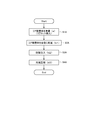
- FIG. 4 is a flow chart showing an example of a rotor manufacturing method according to the first embodiment.
- FIG. 5 is a perspective view showing the mold of the first embodiment.
- FIG. 6 is a vertical cross-sectional view of the traction motor of the second embodiment.
- FIG. 7 is a perspective view showing one side of the rotor according to the second embodiment in the axial direction.
- FIG. 8 is a perspective view showing the other side in the axial direction of the rotor according to the second embodiment.
- FIG. 1 is a perspective view of the rotor according to the first embodiment.
- FIG. 2 is a perspective view showing one side of the resin member according to the first embodiment in the axial direction.
- FIG. 9 is a perspective view showing one side of the core laminate according to the second embodiment in the axial direction.
- FIG. 10 is a perspective view showing the other side in the axial direction of the core laminate according to the second embodiment.
- FIG. 11 is a plan view showing the first core block on one side in the axial direction.
- FIG. 12 is a plan view showing the first end plate on one side in the axial direction.
- FIG. 13 is a plan view showing the second end plate on the other side in the axial direction.
- FIG. 14 is a perspective view of the resin member of the second embodiment.
- FIG. 15 is a flow chart of a rotor manufacturing method according to the second embodiment.
- FIG. 16 is a perspective view showing an example of a mold.
- FIG. 17 is a diagram showing the inner surface of the mold on the other side.
- FIG. 18 is a diagram showing a resin member formed in the mold.
- the direction parallel to the rotation axis of the rotor is referred to as "axial direction”
- the direction orthogonal to the axial direction is referred to as “diameter direction”
- the direction along the arc centered on the rotation axis is referred to as “circumferential direction”.
- the direction approaching the rotation axis is the radial inward direction
- the direction away from the rotation axis is the radial outer direction.
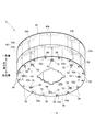
- FIG. 1 is a perspective view of the rotor 3A according to the first embodiment.
- the rotor 3A rotates about the rotation shaft 9A.
- the rotor 3A includes a core laminate 40A.
- the core laminated body 40A is configured by laminating a first core block 41A and a second core block 42A in a plurality of stages in the axial direction.
- Each core block 41A, 42A is formed by laminating a plurality of steel plates.
- the first core block 41A is located at one end in the axial direction
- the second core block 42A is located at the other end in the axial direction.
- the first core block 41A has a plurality of insertion holes 43A arranged in the circumferential direction.
- the second core block 42A also has a plurality of insertion holes 43B arranged in the circumferential direction.
- a magnet 60A is located inside each of the insertion holes 43A and 43B. The magnet 60A is fixed by the resin member 70A inside the insertion holes 43A and 43B.
- the core blocks 41A and 42A are adjacent to each other in the axial direction, and are positioned so as to be offset from each other with respect to the rotation axis 9A. That is, the core laminate 40A has a skew structure.
- the insertion holes 43A and 43B communicate with each other in the axial direction. "Communication” here means a state in which fluids are connected so that they can flow.
- FIG. 2 is a perspective view showing one side of the resin member 70A according to the first embodiment in the axial direction.
- FIG. 3 is a perspective view showing the other side of the resin member 70A according to the first embodiment in the axial direction.
- the resin member 70A includes a filling portion 71A located in the insertion holes 43A and 43B, a first gate portion 73A located on one side in the axial direction of the filling portion 71A, and a filling portion 71A. It has a second gate portion 75A located on the other side in the axial direction.
- FIG. 4 is a flow chart showing an example of a method for manufacturing the rotor 3A according to the first embodiment.
- a preparatory step S1A for preparing the core laminate 40A is performed.
- core blocks 41A and 42A are produced by laminating a plurality of steel plates.
- the first core block 41A is laminated on one side of the second core block 42A in the axial direction while being displaced in the circumferential direction with respect to the second core block 42A about the rotation axis 9A.
- a magnet 60A is inserted into the insertion holes 43A and 43B of the core blocks 41A and 42A.
- the arrangement step S2A for arranging the core laminate 40A in the mold 80A is performed.
- FIG. 5 is a perspective view showing the mold 80A of the first embodiment.
- the mold 80 has a one-side mold 81A and a other-side mold 82A.
- the one-side mold 81A and the other-side mold 82A have a concave inner surface corresponding to the outer shape of the core laminate 40A.
- the one-side mold 81A is provided with a plurality of (8 in this example) injection ports 83A. Each injection port 83A communicates with the insertion hole 43A of the first core block 41A.
- a plurality of concave outlets (8 in this example) 851A are provided on the inner surface of the other side mold 82A, and the outlet 851A is a resin provided inside the other side mold 82A. It communicates with the reservoir 85A.
- each outlet 851A is communicated with the insertion hole 43B of the second core block 42A.
- the injection step S3A is performed after the placement step S2A.
- the injection step S3A by injecting a fluid resin into the injection port 83A of the mold 80A shown in FIG. 5, the resin is injected into each insertion hole 43A and each insertion hole 43B communicating with each insertion hole 43A.
- the filling step S4A is performed.
- the fluid resin injected into the mold 80A by the injection step S3A is filled into the insertion holes 43A and 43B while flowing out from the insertion hole 43B to the resin reservoir 85A through the outlet 851A. ..
- the resin member 70A is formed by curing the resin filled in the insertion holes 43A and 43B in the filling step S4A.
- the first gate portion 73A is a part of a convex portion formed by flowing into the insertion hole 43A from the injection port 83A.
- the second gate portion 75A is a part of a convex portion formed by the resin flowing out to the outlet 851A and the resin pool portion 85A.
- the number of steps is smaller than that in the case where the resin is filled in each of the core blocks 41A and 42A. can do.
- the fluid resin is injected from the injection port 83A of the mold 80A, even if the resin moves partially in the insertion holes 43A and 43B, the previously moved resin is discharged from the insertion hole 43B. It can flow out to the resin reservoir 85A via the 851A.
- the fluid resin can be spread over the entire inside of the insertion holes 43A and 43B, so that it is possible to suppress poor filling of the resin in the insertion holes 43A and 43B. Therefore, the productivity of the rotor 3A can be improved. Further, the position of the magnet 60A in the insertion holes 43A and 43B can be stabilized.
- FIG. 6 is a vertical cross-sectional view of the traction motor 1 of the second embodiment.
- the traction motor 1 is a device mounted on a vehicle such as an electric vehicle or a plug-in hybrid vehicle and outputs a driving force for traveling of the vehicle.
- the traction motor 1 includes a motor 11, a gear 13, and an inverter 15.
- the motor 11 has a stationary portion 2 and a rotor 3.
- the stationary portion 2 rotatably supports the rotor 3.
- the gear 13 is connected to the motor 11.
- the inverter 15 is electrically connected to the motor 11.
- the inverter 15 is a device that converts direct current into alternating current, and supplies the drive current obtained by the conversion to the motor 11.
- the stationary portion 2 has a housing 21, a lid portion 22, a stator 23, a first bearing portion 24, and a second bearing portion 25.
- the housing 21 is a bottomed substantially cylindrical housing that internally houses the stator 23, the first bearing portion 24, the rotor 3, and the shaft 30.
- a recess 211 for holding the first bearing portion 24 is provided in the center of the bottom portion of the housing 21.
- the lid portion 22 is a plate-shaped member that closes the opening on one side of the housing 21 in the axial direction.
- a circular hole 221 for holding the second bearing portion 25 is provided in the center of the lid portion 22.
- the stator 23 generates magnetic flux according to the drive current.
- the stator 23 has a stator core 26 and a coil 27.
- the stator core 26 is made of a laminated steel plate in which a plurality of steel plates are laminated in the axial direction.
- the stator core 26 has an annular core back 261 and a plurality of tooth portions 262 protruding inward in the radial direction from the core back 261.
- the core back 261 is fixed to the inner peripheral surface of the side wall of the housing 21.
- the coil 27 is composed of a conducting wire wound around each tooth portion 262 of the stator core 26.
- the first bearing portion 24 and the second bearing portion 25 are mechanisms that rotatably support the shaft 30 connected to the through hole 3H of the rotor 3.
- ball bearings that relatively rotate the outer ring and the inner ring via a sphere are used.
- bearings of other types such as slide bearings and fluid bearings may be used.
- the outer ring 241 of the first bearing portion 24 is fixed to the recess 211 of the housing 21. Further, the outer ring 251 of the second bearing portion 25 is fixed to the edge of the circular hole 221 of the lid portion 22. On the other hand, the inner rings 242 and 252 of the first bearing portion 24 and the second bearing portion 25 are fixed to the shaft 30. Therefore, the shaft 30 is rotatably supported by the housing 21 and the lid 22.
- the shaft 30 is a substantially columnar member extending in the axial direction along the rotation shaft 9.
- the shaft 30 rotates about a rotating shaft 9 while being supported by the first bearing portion 24 and the second bearing portion 25 described above.
- the shaft 30 has a head portion 301 protruding from the lid portion 22 on one side in the axial direction.
- the head 301 is connected to a driving object of an automobile via a gear 13 which is a power transmission mechanism.
- the rotor 3 rotates together with the shaft 30 inside the stator 23 in the radial direction.
- the rotor 3 has a plurality of magnets 60, as will be described later.
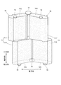
- FIG. 7 is a perspective view showing one side of the rotor 3 according to the second embodiment in the axial direction.
- FIG. 8 is a perspective view showing the other side of the rotor 3 according to the second embodiment in the axial direction.
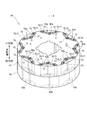
- FIG. 9 is a perspective view showing one side in the axial direction of the core laminated body 40 according to the second embodiment.
- FIG. 10 is a perspective view showing the other side in the axial direction of the core laminated body 40 according to the second embodiment.
- FIG. 11 is a plan view showing the first core block 41 on one side in the axial direction.
- FIG. 12 is a plan view showing the first end plate 51 on one side in the axial direction.
- FIG. 13 is a plan view showing the second end plate 52 on the other side in the axial direction.
- FIG. 14 is a perspective view of the resin member 70 of the second embodiment.
- the rotor 3 has a core laminate 40, a first end plate 51, a second end plate 52, a plurality of magnets 60, and a plurality of resin members 70.
- the core laminate 40 is formed by laminating two first core blocks 41 and a second core block 42 in the axial direction.
- Each of the core blocks 41 and 42 is composed of a plurality of substantially annular steel plates laminated in the axial direction.
- the core blocks 41 and 42 have the same shape and size.
- the core blocks 41 and 42 are adjacent to each other in the axial direction, and are positioned so as to be offset from each other in the circumferential direction with the rotation axis 9 as the center. That is, the core laminate 40 has a so-called skew structure.
- the deviation angle (skew angle) of the second core block 42 with respect to the first core block 41 is, for example, 3.25 °.
- the first core block 41 has 16 insertion holes 43a arranged in the circumferential direction. More specifically, the first core block 41 has eight pairs of insertion holes 43a, 43a that are close to each other in the circumferential direction at equal intervals in the circumferential direction. The pair of insertion holes 43a, 43a are adjacent to each other at intervals in the circumferential direction when viewed from the axial direction, and form a V-shape that separates from each other in the circumferential direction toward the outside in the radial direction.
- the second core block 42 also has 16 insertion holes 43b arranged in the circumferential direction. That is, the second core block 42 has eight pairs of insertion holes 43b and 43b that are close to each other in the circumferential direction at equal intervals in the circumferential direction.
- the pair of insertion holes 43b, 43b also have a V shape when viewed from the axial direction, like the pair of insertion holes 43a, 43a.
- the insertion hole 43b has the same shape and size as the insertion hole 43a.
- the insertion holes 43a and 43b are through holes having a constant opening shape in the axial direction. Each insertion hole 43a communicates with the insertion hole 43b in the axial direction. That is, as shown in FIGS. 7 and 8, the insertion hole 43a and the insertion hole 43b form one continuous continuous hole 43.
- One magnet 60 is arranged in each of the insertion holes 43a and 43b.
- the pair of magnets 60 can be arranged in a V shape. Thereby, the magnetic characteristics of the rotor 3 can be improved.
- magnets 60 are arranged one by one so that the magnetic poles of the surfaces facing outward in the radial direction are the same.
- the magnets 60 arranged in the pair of insertion holes 43a, 43a and the other pair of insertion holes 43a, 43a adjacent to each other in the circumferential direction are arranged so that the magnetic poles of the surfaces facing outward in the radial direction are different.
- the magnet 60 is fixed to the inside of the insertion holes 43a and 43b by the resin member 70 described later.
- the end plates 51 and 52 are the same substantially annular plate-shaped members.
- the first end plate 51 has a plurality of (16 in this example) first through holes 53 and a plurality of (8 in this example) second through holes. It has a third connection hole 55 which is a hole.
- the second end plate 52 also has a plurality of (16 in this example) first through holes 56 and a plurality of (8 in this example) second through holes. It has a second connection hole 54 which is a through hole.
- the plurality of first connection holes 53 are located on the same circumference
- the plurality of third connection holes 55 are located on the same circumference at equal intervals.
- the plurality of fourth connection holes 56 are located on the same circumference
- the second connection holes 54 are located on the same circumference at equal intervals.
- the first end plate 51 is located on one side in the axial direction of the core laminate 40.
- the first end plate 51 faces a plurality of magnets 60 arranged in the insertion holes 43a in the axial direction, and prevents the magnets 60 from falling off from the insertion holes 43a in one axial direction.
- the first connection hole 53 of the first end plate 51 communicates with the insertion hole 43a of the first core block 41. Since the first end plate 51 has the first connection hole 53, the resin member 70 can be filled from one side in the axial direction of the continuous hole 43 after the first end plate 51 is attached to the core laminate 40. is there.
- the second end plate 52 is located on the other side in the axial direction of the core laminate 40.
- the second end plate 52 faces the plurality of magnets 60 arranged in the insertion holes 43b in the axial direction, and prevents the magnets 60 from falling off from the insertion holes 43b in the other direction in the axial direction.
- the second connection hole 54 of the second end plate 52 communicates with the insertion hole 43b of the second core block 42. Since the second end plate 52 has the second connection hole 54, the resin member 70 can flow out from the other side in the axial direction of the continuous hole 43 after the second end plate 52 is attached to the core laminate 40.
- Each of the core blocks 41 and 42 is provided with a pair of insertion holes 43a and 43a and a pair of insertion holes 43b and 43b that are close to each other in the circumferential direction. Therefore, in the rotor 3, as shown in FIG. 14, the pair of resin members 70 are arranged so as to be close to each other in the circumferential direction.
- the resin member 70 has a filling portion 71, a first gate portion 73, and a second gate portion 75.
- the filling portion 71 is located inside the insertion holes 43a and 43b (that is, the continuous holes 43) that communicate with each other in the axial direction.
- the filling portion 71 has a first filling portion 711 located inside the insertion hole 43a and a second filling portion 712 located inside the insertion hole 43b.
- the first gate portion 73 is located on one side in the axial direction of the filling portion 71.
- the first gate portion 73 is a convex portion of the first filling portion 711 that protrudes from the first end surface 71S on one side in the axial direction to one side in the axial direction.
- the first gate portion 73 is a portion provided inside the first connection hole 53.
- the end portion on one side in the axial direction of the first gate portion 73 is located on the other side in the axial direction with respect to the end surface 51S on one side in the axial direction of the first end plate 51. Since the first gate portion 73 does not project axially from the first end plate 51, it is possible to prevent the first gate portion 73 from coming into contact with other members.
- the second gate portion 75 is located on the other side of the filling portion 71 in the axial direction.
- the second gate portion 75 is a convex portion of the second filling portion 712 that protrudes from the second end surface 72S on the other side in the axial direction to the other side in the axial direction.
- the second gate portion 75 is a portion provided in the second connection hole 54.
- the end of the second gate portion 75 on the other side in the axial direction is located on one side in the axial direction with respect to the end surface 52S on the other side in the axial direction of the second end plate 52. Since the second gate portion 75 does not project axially from the second end plate 52, it is possible to prevent the second gate portion 75 from coming into contact with other members.
- the resin member 70 When forming the resin member 70, the resin is injected into the first connection hole 53 of the first end plate 51. Then, the resin enters the insertion hole 43a of the first core block 41 and the insertion hole 43b of the second core block 42 through the first connection hole 53. Further, some resin flows out from the insertion hole 43b through the second connection hole 54.
- the second connection hole 54 As shown in FIG. 13, the second connection hole 54 is arranged at a position where it overlaps both of the pair of insertion holes 43b and 43b in the axial direction. Therefore, as shown in FIG. 14, a pair of filling portions 71, 71 (more specifically, a pair of second gate portions) that are close to each other in the circumferential direction by one second gate portion 75 formed in the second connection hole 54. Filling portions 712,712) are connected.
- the second connection hole 54 in the second end plate 52 is located closer to the rotation shaft 9 than the first connection hole 53 in the first end plate 51. Therefore, the second gate portion 75 located in the second connection hole 54 is located closer to the rotation shaft 9 than the first gate portion 73 provided in the first connection hole 53.
- the resin flows from the outer side in the radial direction to the inner side in the radial direction in the continuous hole 43. Therefore, the magnet 60 can be fixed while being pressed against the radial inner surface of the continuous hole 43, and the magnet 60 can be stably arranged in the continuous hole 43.
- the second gate portion 75 provided on the pair of resin members 70, 70 is located between the pair of first gate portions 73, 73 of each of the pair of resin members 70, 70 in the circumferential direction. To position.
- the third connection hole 55 of the first end plate 51 communicates with a pair of insertion holes 43a, 43a that are close to each other in the circumferential direction. That is, the third connection hole 55 is provided at a position straddling the pair of insertion holes 43a, 43a.
- the third connection hole 55 releases the gas generated from the resin from the insertion hole 43a when the continuous hole 43 is filled with the resin.
- a convex portion 77 is formed on the first end surface 71S of the resin member 70 by the third connection hole 55.
- the pair of resin members 70, 70 (more specifically, the pair of first filling portions 711 and 711) that are close to each other in the circumferential direction are connected by one convex portion 77 provided on one side in the axial direction. ..
- the convex portion 77 located in the third connection hole 55 is located closer to the rotation shaft 9 than the first gate portion 73 located in the first connection hole 53.
- the fourth connection hole 56 of the second end plate 52 communicates with the insertion hole 43b of the second core block 42.
- a convex portion 79 is formed in the resin member 70 by the fourth connection hole 56.
- the convex portion 79 is provided on the second end surface 72S of the filling portion 71.
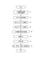
- FIG. 15 is a flow chart of a manufacturing method of the rotor 3 according to the second embodiment.
- a preparatory step S1 for preparing the core laminate 40 is performed.
- the core blocks 41 and 42 adjacent to each other in the axial direction are arranged so as to be offset from each other with respect to the rotation axis 9, and the insertion holes 43a and 43b of the core blocks 41 and 42 adjacent to each other in the axial direction communicate with each other in the axial direction. It is said that it is in a state of being.
- the preparation step S1 includes a magnet insertion step of inserting the magnet 60 into the insertion holes 43a and 43b.
- the third welding step S4 for welding the end plate 52 is performed.
- a laminate having the first end plate 51, the core blocks 41, 42, and the second end plate 52 is formed.
- the welding position is not particularly limited.
- a plurality of locations dispersed in the circumferential direction on the outer peripheral portion of the first end plate 51 (in the illustrated example, the first end plate 51 is welded).
- Welding may be performed at the welding positions P1 (8 locations).
- welding may be performed at a plurality of welding positions (4 locations in the illustrated example) dispersed in the circumferential direction.
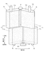
- FIG. 16 is a perspective view showing an example of the mold 80.
- FIG. 17 is a diagram showing an inner surface 82S of the other side mold 82.
- the core laminated body 40 is shown by a broken line.
- the second core block 42 and the second end plate 52 are shown by broken lines.
- the mold 80 has a one-sided mold 81 arranged on one side in the axial direction and a other-side mold 82 arranged on the other side in the axial direction.
- the one-side mold 81 and the other-side mold 82 may each be configured by combining a plurality of members.
- the one-side mold 81 is provided with a plurality of (16 in this case) injection ports 83.
- each injection port 83 is communicated with the insertion hole 43a of the first core block 41 via the first connection hole 53 of the first end plate 51.
- a plurality of (here, eight) outlets 851 are provided on the inner surface 82S of the other side mold 82.
- the outflow port 851 communicates with the resin reservoir 85 provided inside the mold 82 on the other side.
- the second connection hole 54 of the second end plate 52 vertically overlaps the outlet 851.
- the resin reservoir 85 is communicated with the insertion hole 43b of the second core block 42 via the outlet 851 and the second connection hole 54.
- the fourth connection hole 56 of the second end plate 52 is closed by the inner surface 82S of the other side mold 82.
- the one-side mold 81 is provided with a plurality of (here, eight) outlets 87.
- the discharge port 87 communicates with the insertion hole 43a of the first core block 41 via the third connection hole 55. It is desirable that the diameter of the discharge port 87 is such that only the gas generated from the resin passes through and the resin does not flow into the discharge port 87. As a result, the resin does not flow out from the discharge port 87, and it is possible to suppress the formation of burrs.
- the diameter of the outlet 87 on the other side in the axial direction is preferably smaller than the diameter of the inlet 83 on the other side in the axial direction.
- an injection step S6 for injecting a fluid resin into the injection port 83 is performed.
- the resin is injected into the 16 injection ports 83 at almost the same time. It is not essential to inject the resin into all the injection ports 83 at the same time.
- a filling step S7 is performed in which the inside of the continuous hole 43 is filled with a fluid resin.
- the gap between the inner peripheral surface of the insertion hole 43a and the magnet 60 and the space between the inner peripheral surface of the insertion hole 43b and the magnet 60 are filled with resin.
- the fluid resin injected into the mold 80 is discharged to the resin reservoir 85 via the outlet 851 provided in the mold 82 on the other side.
- the resin that has moved to the other side in the axial direction first flows out from the continuous hole 43 to the resin reservoir 85 through the outlet 851 of the mold 80. Can be made to. Therefore, the inside of the continuous hole 43 can be satisfactorily filled with resin.
- the pair of insertion holes 43a and 43a and the pair of insertion holes 43b and 43b that are close to each other in the circumferential direction are arranged so as to be displaced in the circumferential direction. Therefore, there is a difference in the shape and size of the overlap between the pair of insertion holes 43a and 43a and the pair of insertion holes 43b and 43b. Due to this difference in overlap, a difference in filling speed may occur between the pair of continuous holes 43.
- the resin having the faster filling rate can flow out from the outflow port 851 to the resin reservoir 85. Therefore, the resin can be satisfactorily distributed in both of the pair of continuous holes 43 and 43.
- the resin moving through the pair of continuous holes 43, 43 can flow out to the resin reservoir 85 through the second connection hole 54 communicating with both of the pair of continuous holes 43, 43. Therefore, the amount of resin flowing out can be reduced as compared with the case where the second connection hole 54 is provided for each continuous hole 43.
- the filling step S7 when gas is generated from the resin injected into the continuous hole 43, the gas is discharged to the outside of the mold 80 from the discharge port 87 communicating with the insertion hole 43a. As a result, it is possible to suppress defective filling of the resin due to filling with gas.
- the resin is cured by cooling, and then the core laminate 40 is taken out from the mold 80. Subsequently, the removal step S8 for removing a part of the first gate portion 73 and the second gate portion 75 from the core laminated body 40 is performed.
- FIG. 18 is a diagram showing a resin member 70 formed in the mold 80.
- the resin member 70 formed in the mold 80 has a first gate portion 731 having a shape corresponding to the injection port 83 and a second gate portion 731 having a shape corresponding to the outlet 851 and the resin pool portion 85. It has a gate portion 751.
- the first gate portion 731 has a portion protruding from the first connection hole 53.
- the first gate portion 73 shown in FIG. 14 is provided by removing the portion of the first gate portion 731 that protrudes from the first connection hole 53.
- the second gate portion 751 shown in FIG. 18 has a portion protruding from the second connection hole 54.
- the second gate portion 75 shown in FIG. 14 is provided by removing the portion of the second gate portion 751 that protrudes from the second connection hole 54.
- the number of steps is larger than that in the case of filling the resin in each of the core blocks 41 and 42. Can be reduced.
- the fluid resin is injected from the injection port 83 of the mold 80, even if the resin moves partially in the continuous hole 43, the resin that has moved earlier is inserted into the outlet 851 from the insertion hole 43b. It can be discharged to the resin reservoir 85 through the resin reservoir 85.
- the fluid resin can be spread over the entire inside of the insertion holes 43a and 43b, so that poor filling of the resin in the insertion holes 43a and 43b can be suppressed. Therefore, the productivity of the rotor 3 can be improved. Further, the position of the magnet 60 in the insertion holes 43a and 43b can be stabilized.
- welding between the core blocks 41 and 42 of the core laminate 40, welding between the core laminate 40 and the first end plate 51, and welding between the core laminate 40 and the second end plate 52 is performed once. Can be done. Thereby, the productivity of the traction motor 1 can be improved.
- the second end plate 52 can be made by inverting the first end plate 51. This eliminates the need to individually manufacture the end plates 51 and 52. Further, by using the end plates 51 and 52 as plate members having the same shape provided with the first through holes (connection holes 53 and 56) and the second through holes (connection holes 55 and 54), the end plates 51 and 52 are formed. Is attached to the core laminate 40, and then the insertion holes 43a and 43b of the core laminate 40 can be filled with resin.
- the core laminate 40 is composed of two core blocks 41 and 42, but one or more core blocks may be provided between these core blocks 41 and 42. That is, the core laminated body 40 may be configured by laminating core blocks in three or more stages.
- each member is connected by other means such as caulking or screwing. May be good.
- the present invention can be used for rotors.
Abstract
This rotor rotates about a rotating axis. The rotor is provided with: a core stack composed of core blocks stacked in a plurality of stages in the axial direction of the rotating axis, the core blocks each composed of a plurality of steel sheets stacked in the axial direction and having a plurality of insertion holes arranged in a circumferential direction; a plurality of magnets positioned on the inside of the plurality of insertion holes; and a plurality of resin members fixing the magnets on the inside of the plurality of insertion holes. The core blocks that are adjacent to each other in the axial direction are positioned at mutually staggered angles about the center of the rotating axis. The insertion holes of the core blocks that are adjacent to each other in the axial direction are in communication with each other in the axial direction. The resin members are each provided with a filling portion position in the insertion holes, a first gate portion positioned on one side of the filling portion in the axial direction, and a second gate portion positioned on the other side of the filling portion in the axial direction.
Description
この発明は、ロータに関する。本願は、2019年9月30日に日本に出願された特願2019-179309号に基づき優先権を主張し、その内容をここに援用する。
The present invention relates to a rotor. The present application claims priority based on Japanese Patent Application No. 2019-179309 filed in Japan on September 30, 2019, the contents of which are incorporated herein by reference.
特開2018-7483号公報には、複数の電磁鋼板を軸線方向に積層することによって構成され、複数の永久磁石が埋め込まれた回転子鉄心が記載されている。回転子鉄心は、永久磁石の位置が、軸方向に関して段階的に周方向へずらされた段スキューの構成を有している。
Japanese Unexamined Patent Publication No. 2018-7843 describes a rotor core which is formed by laminating a plurality of electromagnetic steel sheets in the axial direction and in which a plurality of permanent magnets are embedded. The rotor core has a step skew configuration in which the positions of the permanent magnets are gradually shifted in the circumferential direction with respect to the axial direction.
段スキューの回転子鉄心を製造するため、特開2018-7483号公報では、1段目の磁石挿入孔に接着剤を注入する注入工程、磁石挿入孔に永久磁石を挿入する挿入工程、磁石挿入孔に接着剤を充填する充填工程が、順に行われる。そして、2段目の複数の電磁鋼板を1段目に対して所定のスキュー角だけ周方向にずらして積層する積層工程が行われた後、2段目の磁石挿入孔に対して、注入工程、挿入工程および充填工程が行われる。このような製造方法により、永久磁石の外表面のより広い範囲を接着剤で覆うことが可能であるため、回転子鉄心の高速回転時に永久磁石に作用する応力を緩和することができる、とされている。
特開2018-7483号公報
In order to manufacture a rotor core with a step skew, Japanese Patent Application Laid-Open No. 2018-7483 discloses an injection step of injecting an adhesive into the first-stage magnet insertion hole, an insertion step of inserting a permanent magnet into the magnet insertion hole, and a magnet insertion. The filling steps of filling the holes with the adhesive are performed in sequence. Then, after performing a laminating step of laminating a plurality of electrical steel sheets in the second stage by shifting them by a predetermined skew angle in the circumferential direction with respect to the first stage, an injection step is performed in the magnet insertion holes of the second stage. , Insertion step and filling step are performed. According to such a manufacturing method, it is possible to cover a wider range of the outer surface of the permanent magnet with an adhesive, so that the stress acting on the permanent magnet during high-speed rotation of the rotor core can be relaxed. ing.
JP-A-2018-7843
しかしながら、上記従来技術の場合、接着剤の注入および充填を段毎に行うため、作業工程数が多くなっていた。このため、ロータの生産性が低下するという問題があった。
However, in the case of the above-mentioned conventional technique, the number of work steps is increased because the injection and filling of the adhesive are performed step by step. Therefore, there is a problem that the productivity of the rotor is lowered.
本発明の目的は、スキュー構造を有するロータの生産効率を向上する技術を提供することにある。
An object of the present invention is to provide a technique for improving the production efficiency of a rotor having a skew structure.
上記課題を解決するため、第1態様は、回転軸を中心に回転するロータであって、回転軸の軸方向に積層された複数の鋼板で構成され周方向に並ぶ複数の挿入孔を有するコアブロックが、軸方向に複数段に積層されることによって構成されるコア積層体と、前記複数の挿入孔の内側に位置する複数のマグネットと、前記マグネットを前記複数の挿入孔の内側に固定する複数の樹脂部材と、を備え、軸方向に隣接する前記コアブロックが、前記回転軸を中心として互いに角度をずらして位置し、軸方向に隣接する前記コアブロックの前記挿入孔が、互いに軸方向に連通し、前記樹脂部材は、前記挿入孔内に位置する充填部と、前記充填部における軸方向一方側に位置する第1ゲート部と、前記充填部における軸方向他方側に位置する第2ゲート部と、を備える。
In order to solve the above problems, the first aspect is a rotor that rotates about a rotation axis, which is composed of a plurality of steel plates laminated in the axial direction of the rotation axis and has a plurality of insertion holes arranged in the circumferential direction. A core laminate formed by stacking blocks in a plurality of stages in the axial direction, a plurality of magnets located inside the plurality of insertion holes, and the magnets fixed to the inside of the plurality of insertion holes. The core blocks provided with a plurality of resin members and adjacent to each other in the axial direction are located at different angles with respect to the rotation axis, and the insertion holes of the core blocks adjacent to each other in the axial direction are axial to each other. The resin member is connected to a filling portion located in the insertion hole, a first gate portion located on one side of the filling portion in the axial direction, and a second gate portion located on the other side of the filling portion in the axial direction. It is provided with a gate portion.
上記構成のロータによると、軸方向に連通する挿入孔に対して一度に樹脂を充填することによって、コアブロック毎に樹脂を充填する場合よりも作業工程数を少なくすることができる。また、第1ゲート部に対応する金型の流入口を介して挿入孔に流動状の樹脂を注入した際に、挿入孔内を樹脂が一部分に偏って移動したとしても、先に移動した樹脂を、軸方向他方側のコアブロックの挿入孔から第2ゲート部に対応する金型の流出口を介して流出させることができる。これにより、挿入孔の内側全体に流動状の樹脂を行き渡らせることができるため、挿入孔内における樹脂の充填不良を抑制することができる。したがって、ロータの生産性を向上することができる。
According to the rotor having the above configuration, by filling the insertion holes communicating in the axial direction with the resin at one time, the number of work steps can be reduced as compared with the case where the resin is filled for each core block. Further, when the fluid resin is injected into the insertion hole through the inflow port of the mold corresponding to the first gate portion, even if the resin moves partially in the insertion hole, the resin that has moved first. Can flow out from the insertion hole of the core block on the other side in the axial direction through the outlet of the mold corresponding to the second gate portion. As a result, the fluid resin can be spread over the entire inside of the insertion hole, so that it is possible to suppress poor filling of the resin in the insertion hole. Therefore, the productivity of the rotor can be improved.
以下、添付の図面を参照しながら、本発明の実施形態について説明する。なお、この実施形態に記載されている構成要素はあくまでも例示であり、本発明の範囲をそれらのみに限定する趣旨のものではない。図面においては、理解容易のため、必要に応じて各部の寸法や数が誇張又は簡略化して図示されている場合がある。
Hereinafter, embodiments of the present invention will be described with reference to the accompanying drawings. It should be noted that the components described in this embodiment are merely examples, and the scope of the present invention is not limited to them. In the drawings, the dimensions and numbers of each part may be exaggerated or simplified as necessary for easy understanding.
以下では、ロータの回転軸と平行な方向を「軸方向」、軸方向に直交する方向を「径方向」、回転軸を中心とする円弧に沿う方向を「周方向」、と称する。径方向のうち、回転軸に接近する方向を径方向内方とし、回転軸から離れる方向を径方向外方とする。
Hereinafter, the direction parallel to the rotation axis of the rotor is referred to as "axial direction", the direction orthogonal to the axial direction is referred to as "diameter direction", and the direction along the arc centered on the rotation axis is referred to as "circumferential direction". Of the radial directions, the direction approaching the rotation axis is the radial inward direction, and the direction away from the rotation axis is the radial outer direction.
<1. 第1実施形態>
図1は、第1実施形態に係るロータ3Aの斜視図である。ロータ3Aは、回転軸9Aを中心に回転する。ロータ3Aは、コア積層体40Aを備える。コア積層体40Aは、第1コアブロック41Aと第2コアブロック42Aとが軸方向に複数段に積層されて構成される。各コアブロック41A,42Aは、複数の鋼板を積層することによって構成される。コア積層体40Aにおいて、軸方向一方側の端に第1コアブロック41Aが位置し、軸方向他方側の端に第2コアブロック42Aが位置する。 <1. First Embodiment>
FIG. 1 is a perspective view of therotor 3A according to the first embodiment. The rotor 3A rotates about the rotation shaft 9A. The rotor 3A includes a core laminate 40A. The core laminated body 40A is configured by laminating a first core block 41A and a second core block 42A in a plurality of stages in the axial direction. Each core block 41A, 42A is formed by laminating a plurality of steel plates. In the core laminate 40A, the first core block 41A is located at one end in the axial direction, and the second core block 42A is located at the other end in the axial direction.
図1は、第1実施形態に係るロータ3Aの斜視図である。ロータ3Aは、回転軸9Aを中心に回転する。ロータ3Aは、コア積層体40Aを備える。コア積層体40Aは、第1コアブロック41Aと第2コアブロック42Aとが軸方向に複数段に積層されて構成される。各コアブロック41A,42Aは、複数の鋼板を積層することによって構成される。コア積層体40Aにおいて、軸方向一方側の端に第1コアブロック41Aが位置し、軸方向他方側の端に第2コアブロック42Aが位置する。 <1. First Embodiment>
FIG. 1 is a perspective view of the
第1コアブロック41Aは、周方向に並ぶ複数の挿入孔43Aを有する。第1コアブロック41Aと同様に、第2コアブロック42Aも、周方向に並ぶ複数の挿入孔43Bを有する。挿入孔43A,43B各々の内側には、マグネット60Aが位置する。マグネット60Aは、挿入孔43A,43Bの内側において、樹脂部材70Aにより固定される。
The first core block 41A has a plurality of insertion holes 43A arranged in the circumferential direction. Like the first core block 41A, the second core block 42A also has a plurality of insertion holes 43B arranged in the circumferential direction. A magnet 60A is located inside each of the insertion holes 43A and 43B. The magnet 60A is fixed by the resin member 70A inside the insertion holes 43A and 43B.
コアブロック41A、42Aは、軸方向に隣接しており、回転軸9Aを中心として互いに角度をずらして位置する。すなわち、コア積層体40Aは、スキュー構造を有する。挿入孔43A,43Bは、互いに軸方向に連通する。「連通」とは、ここでは、流体が流通できるように連結されている状態をいう。
The core blocks 41A and 42A are adjacent to each other in the axial direction, and are positioned so as to be offset from each other with respect to the rotation axis 9A. That is, the core laminate 40A has a skew structure. The insertion holes 43A and 43B communicate with each other in the axial direction. "Communication" here means a state in which fluids are connected so that they can flow.
図2は、第1実施形態に係る樹脂部材70Aの軸方向一方側を示す斜視図である。図3は、第1実施形態に係る樹脂部材70Aの軸方向他方側を示す斜視図である。図2および図3に示すように、樹脂部材70Aは、挿入孔43A,43Bに位置する充填部71Aと、充填部71Aにおける軸方向一方側に位置する第1ゲート部73Aと、充填部71Aにおける軸方向他方側に位置する第2ゲート部75Aとを有する。
FIG. 2 is a perspective view showing one side of the resin member 70A according to the first embodiment in the axial direction. FIG. 3 is a perspective view showing the other side of the resin member 70A according to the first embodiment in the axial direction. As shown in FIGS. 2 and 3, the resin member 70A includes a filling portion 71A located in the insertion holes 43A and 43B, a first gate portion 73A located on one side in the axial direction of the filling portion 71A, and a filling portion 71A. It has a second gate portion 75A located on the other side in the axial direction.
<ロータ3Aの製造方法>
図4は、第1実施形態に係るロータ3Aの製造方法の一例を示す流れ図である。ロータ3Aを製造するため、まず、コア積層体40Aを準備する準備工程S1Aが行われる。準備工程S1Aでは、複数の鋼板を積層することによって、コアブロック41A,42Aが作製される。そして、第1コアブロック41Aが、第2コアブロック42Aの軸方向一方側に、第2コアブロック42Aに対して回転軸9Aを中心に周方向へずらして積層される。また、コアブロック41A、42Aの各挿入孔43A,43Bには、マグネット60Aが挿入される。準備工程S1Aによってコア積層体40Aが準備されると、当該コア積層体40Aを金型80A内に配置する配置工程S2Aが行われる。 <Manufacturing method ofrotor 3A>
FIG. 4 is a flow chart showing an example of a method for manufacturing therotor 3A according to the first embodiment. In order to manufacture the rotor 3A, first, a preparatory step S1A for preparing the core laminate 40A is performed. In the preparation step S1A, core blocks 41A and 42A are produced by laminating a plurality of steel plates. Then, the first core block 41A is laminated on one side of the second core block 42A in the axial direction while being displaced in the circumferential direction with respect to the second core block 42A about the rotation axis 9A. Further, a magnet 60A is inserted into the insertion holes 43A and 43B of the core blocks 41A and 42A. When the core laminate 40A is prepared by the preparation step S1A, the arrangement step S2A for arranging the core laminate 40A in the mold 80A is performed.
図4は、第1実施形態に係るロータ3Aの製造方法の一例を示す流れ図である。ロータ3Aを製造するため、まず、コア積層体40Aを準備する準備工程S1Aが行われる。準備工程S1Aでは、複数の鋼板を積層することによって、コアブロック41A,42Aが作製される。そして、第1コアブロック41Aが、第2コアブロック42Aの軸方向一方側に、第2コアブロック42Aに対して回転軸9Aを中心に周方向へずらして積層される。また、コアブロック41A、42Aの各挿入孔43A,43Bには、マグネット60Aが挿入される。準備工程S1Aによってコア積層体40Aが準備されると、当該コア積層体40Aを金型80A内に配置する配置工程S2Aが行われる。 <Manufacturing method of
FIG. 4 is a flow chart showing an example of a method for manufacturing the
図5は、第1実施形態の金型80Aを示す斜視図である。図5に示すように、金型80は、一方側金型81Aと他方側金型82Aを有する。一方側金型81Aおよび他方側金型82Aは、コア積層体40Aの外形に対応する凹状の内面を有する。一方側金型81Aには、複数(本例では、8個)の注入口83Aが設けられる。各注入口83Aは、第1コアブロック41Aの挿入孔43Aに連通する。他方側金型82Aの内面には、凹状である複数(本例では、8個)の流出口851Aが設けられており、当該流出口851Aは、他方側金型82Aの内部に設けられた樹脂溜まり部85Aに連通する。コア積層体40Aが金型80A内に配置されると、各流出口851Aが第2コアブロック42Aの挿入孔43Bに連通される。
FIG. 5 is a perspective view showing the mold 80A of the first embodiment. As shown in FIG. 5, the mold 80 has a one-side mold 81A and a other-side mold 82A. The one-side mold 81A and the other-side mold 82A have a concave inner surface corresponding to the outer shape of the core laminate 40A. The one-side mold 81A is provided with a plurality of (8 in this example) injection ports 83A. Each injection port 83A communicates with the insertion hole 43A of the first core block 41A. A plurality of concave outlets (8 in this example) 851A are provided on the inner surface of the other side mold 82A, and the outlet 851A is a resin provided inside the other side mold 82A. It communicates with the reservoir 85A. When the core laminate 40A is arranged in the mold 80A, each outlet 851A is communicated with the insertion hole 43B of the second core block 42A.
図4に戻って、配置工程S2Aの後、注入工程S3Aが行われる。注入工程S3Aでは、図5に示す金型80Aの注入口83Aに流動状の樹脂を注入することによって、各挿入孔43A、および、各挿入孔43Aに連通する各挿入孔43Bに樹脂が注入される。
Returning to FIG. 4, the injection step S3A is performed after the placement step S2A. In the injection step S3A, by injecting a fluid resin into the injection port 83A of the mold 80A shown in FIG. 5, the resin is injected into each insertion hole 43A and each insertion hole 43B communicating with each insertion hole 43A. To.
続いて、充填工程S4Aが行われる。充填工程S4Aでは、注入工程S3Aによって金型80A内に注入された流動状の樹脂を、挿入孔43Bから流出口851Aを介して樹脂溜まり部85Aへ流出させつつ、挿入孔43A,43Bに充填する。
Subsequently, the filling step S4A is performed. In the filling step S4A, the fluid resin injected into the mold 80A by the injection step S3A is filled into the insertion holes 43A and 43B while flowing out from the insertion hole 43B to the resin reservoir 85A through the outlet 851A. ..
充填工程S4Aによって挿入孔43A,43Bに充填された樹脂が硬化することにより、樹脂部材70Aが形成される。樹脂部材70Aのうち、第1ゲート部73Aは、注入口83Aから挿入孔43Aに流れ込むことによって形成される凸部の一部である。また、第2ゲート部75Aは、流出口851Aおよび樹脂溜まり部85Aへ樹脂が流出することによって形成される凸部の一部である。
The resin member 70A is formed by curing the resin filled in the insertion holes 43A and 43B in the filling step S4A. Of the resin member 70A, the first gate portion 73A is a part of a convex portion formed by flowing into the insertion hole 43A from the injection port 83A. The second gate portion 75A is a part of a convex portion formed by the resin flowing out to the outlet 851A and the resin pool portion 85A.
上記ロータ3Aの構成および製造方法によると、軸方向に連通する挿入孔43A,43Bに対して一度に樹脂を充填するため、コアブロック41A,42A毎に樹脂を充填する場合よりも工程数を少なくすることができる。また、金型80Aの注入口83Aから流動状の樹脂を注入した際に、挿入孔43A,43B内を樹脂が一部分に偏って移動したとしても、先に移動した樹脂を挿入孔43Bから流出口851Aを介して樹脂溜まり部85Aへ流出させることができる。これにより、各挿入孔43A,43Bの内側全体に流動状の樹脂を行き渡らせることができるため、挿入孔43A,43B内における樹脂の充填不良を抑制することができる。したがって、ロータ3Aの生産性を向上することができる。また、挿入孔43A,43Bにおけるマグネット60Aの位置を安定させることができる。
According to the configuration and manufacturing method of the rotor 3A, since the resin is filled into the insertion holes 43A and 43B communicating in the axial direction at once, the number of steps is smaller than that in the case where the resin is filled in each of the core blocks 41A and 42A. can do. Further, when the fluid resin is injected from the injection port 83A of the mold 80A, even if the resin moves partially in the insertion holes 43A and 43B, the previously moved resin is discharged from the insertion hole 43B. It can flow out to the resin reservoir 85A via the 851A. As a result, the fluid resin can be spread over the entire inside of the insertion holes 43A and 43B, so that it is possible to suppress poor filling of the resin in the insertion holes 43A and 43B. Therefore, the productivity of the rotor 3A can be improved. Further, the position of the magnet 60A in the insertion holes 43A and 43B can be stabilized.
<2. 第2実施形態>
図6は、第2実施形態のトラクションモータ1の縦断面図である。トラクションモータ1は、例えば、電気自動車やプラグインハイブリッド車等の車両に搭載され、車両の走行用の駆動力を出力する装置である。トラクションモータ1は、モータ11と、ギア13と、インバータ15とを備える。モータ11は、静止部2と、ロータ3とを有する。静止部2は、ロータ3を回転可能に支持する。ギア13は、モータ11に接続される。インバータ15は、モータ11と電気的に接続される。インバータ15は、直流を交流に変換する装置であり、変換により得られる駆動電流をモータ11へ供給する。 <2. Second Embodiment>
FIG. 6 is a vertical cross-sectional view of thetraction motor 1 of the second embodiment. The traction motor 1 is a device mounted on a vehicle such as an electric vehicle or a plug-in hybrid vehicle and outputs a driving force for traveling of the vehicle. The traction motor 1 includes a motor 11, a gear 13, and an inverter 15. The motor 11 has a stationary portion 2 and a rotor 3. The stationary portion 2 rotatably supports the rotor 3. The gear 13 is connected to the motor 11. The inverter 15 is electrically connected to the motor 11. The inverter 15 is a device that converts direct current into alternating current, and supplies the drive current obtained by the conversion to the motor 11.
図6は、第2実施形態のトラクションモータ1の縦断面図である。トラクションモータ1は、例えば、電気自動車やプラグインハイブリッド車等の車両に搭載され、車両の走行用の駆動力を出力する装置である。トラクションモータ1は、モータ11と、ギア13と、インバータ15とを備える。モータ11は、静止部2と、ロータ3とを有する。静止部2は、ロータ3を回転可能に支持する。ギア13は、モータ11に接続される。インバータ15は、モータ11と電気的に接続される。インバータ15は、直流を交流に変換する装置であり、変換により得られる駆動電流をモータ11へ供給する。 <2. Second Embodiment>
FIG. 6 is a vertical cross-sectional view of the
静止部2は、ハウジング21と、蓋部22と、ステータ23と、第1軸受部24と、第2軸受部25とを有する。ハウジング21は、ステータ23と、第1軸受部24と、ロータ3と、シャフト30とを内部に収容する、有底略円筒状の筐体である。ハウジング21の底部の中央には、第1軸受部24を保持するための凹部211が設けられる。蓋部22は、ハウジング21の軸方向一方側の開口を閉塞する板状の部材である。蓋部22の中央には、第2軸受部25を保持するための円孔221が設けられる。
The stationary portion 2 has a housing 21, a lid portion 22, a stator 23, a first bearing portion 24, and a second bearing portion 25. The housing 21 is a bottomed substantially cylindrical housing that internally houses the stator 23, the first bearing portion 24, the rotor 3, and the shaft 30. A recess 211 for holding the first bearing portion 24 is provided in the center of the bottom portion of the housing 21. The lid portion 22 is a plate-shaped member that closes the opening on one side of the housing 21 in the axial direction. A circular hole 221 for holding the second bearing portion 25 is provided in the center of the lid portion 22.
ステータ23は、駆動電流に応じて磁束を発生させる。ステータ23は、ステータコア26と、コイル27とを有する。ステータコア26は、複数の鋼板を軸方向に積層した積層鋼板からなる。ステータコア26は、円環状のコアバック261と、コアバック261から径方向内側へ向けて突出した複数のティース部262と、を有する。コアバック261は、ハウジング21の側壁の内周面に、固定されている。コイル27は、ステータコア26の各ティース部262に巻回された導線により、構成されている。
The stator 23 generates magnetic flux according to the drive current. The stator 23 has a stator core 26 and a coil 27. The stator core 26 is made of a laminated steel plate in which a plurality of steel plates are laminated in the axial direction. The stator core 26 has an annular core back 261 and a plurality of tooth portions 262 protruding inward in the radial direction from the core back 261. The core back 261 is fixed to the inner peripheral surface of the side wall of the housing 21. The coil 27 is composed of a conducting wire wound around each tooth portion 262 of the stator core 26.
第1軸受部24および第2軸受部25は、ロータ3の貫通孔3Hに連結されたシャフト30を回転可能に支持する機構である。本実施形態の第1軸受部24および第2軸受部25には、球体を介して外輪と内輪とを相対回転させるボールベアリングが、使用されている。ただし、ボールベアリングに代えて、すべり軸受や流体軸受等の他方式の軸受が使用されてもよい。
The first bearing portion 24 and the second bearing portion 25 are mechanisms that rotatably support the shaft 30 connected to the through hole 3H of the rotor 3. In the first bearing portion 24 and the second bearing portion 25 of the present embodiment, ball bearings that relatively rotate the outer ring and the inner ring via a sphere are used. However, instead of ball bearings, bearings of other types such as slide bearings and fluid bearings may be used.
第1軸受部24の外輪241は、ハウジング21の凹部211に固定される。また、第2軸受部25の外輪251は、蓋部22の円孔221の縁に固定される。一方、第1軸受部24および第2軸受部25の内輪242,252は、シャフト30に固定される。このため、シャフト30は、ハウジング21および蓋部22に対して、回転可能に支持される。
The outer ring 241 of the first bearing portion 24 is fixed to the recess 211 of the housing 21. Further, the outer ring 251 of the second bearing portion 25 is fixed to the edge of the circular hole 221 of the lid portion 22. On the other hand, the inner rings 242 and 252 of the first bearing portion 24 and the second bearing portion 25 are fixed to the shaft 30. Therefore, the shaft 30 is rotatably supported by the housing 21 and the lid 22.
シャフト30は、回転軸9に沿って軸方向に延びる略円柱状の部材である。シャフト30は、上述した第1軸受部24および第2軸受部25に支持されつつ、回転軸9を中心として回転する。また、シャフト30は、蓋部22より軸方向一方側に突出した頭部301を有する。頭部301は、動力伝達機構であるギア13を介して、自動車の駆動対象物に連結される。ロータ3は、ステータ23の径方向内側において、シャフト30とともに回転する。ロータ3は、後述するように、複数のマグネット60を有する。
The shaft 30 is a substantially columnar member extending in the axial direction along the rotation shaft 9. The shaft 30 rotates about a rotating shaft 9 while being supported by the first bearing portion 24 and the second bearing portion 25 described above. Further, the shaft 30 has a head portion 301 protruding from the lid portion 22 on one side in the axial direction. The head 301 is connected to a driving object of an automobile via a gear 13 which is a power transmission mechanism. The rotor 3 rotates together with the shaft 30 inside the stator 23 in the radial direction. The rotor 3 has a plurality of magnets 60, as will be described later.
モータ11において、ステータ23のコイル27にインバータ15から駆動電流が与えられると、ステータコア26の複数のティース部262に、径方向の磁束が発生する。そして、ティース部262とマグネット60との間の磁力の作用によって、周方向のトルクが発生する。その結果、ステータ23に対して、ロータ3が回転軸9を中心として回転する。ロータ3が回転すると、シャフト30に連結されたギア13に回転駆動力が伝達される。
In the motor 11, when a drive current is applied to the coil 27 of the stator 23 from the inverter 15, magnetic flux in the radial direction is generated in the plurality of teeth portions 262 of the stator core 26. Then, torque in the circumferential direction is generated by the action of the magnetic force between the teeth portion 262 and the magnet 60. As a result, the rotor 3 rotates about the rotation shaft 9 with respect to the stator 23. When the rotor 3 rotates, the rotational driving force is transmitted to the gear 13 connected to the shaft 30.
<ロータ3の構成>
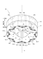
図7は、第2実施形態に係るロータ3の軸方向一方側を示す斜視図である。図8は、第2実施形態に係るロータ3の軸方向他方側を示す斜視図である。図9は、第2実施形態に係るコア積層体40の軸方向一方側を示す斜視図である。図10は、第2実施形態に係るコア積層体40の軸方向他方側を示す斜視図である。図11は、軸方向一方側の第1コアブロック41を示す平面図である。図12は、軸方向一方側の第1エンドプレート51を示す平面図である。図13は、軸方向他方側の第2エンドプレート52を示す平面図である。図14は、第2実施形態の樹脂部材70の斜視図である。 <Structure ofrotor 3>
FIG. 7 is a perspective view showing one side of therotor 3 according to the second embodiment in the axial direction. FIG. 8 is a perspective view showing the other side of the rotor 3 according to the second embodiment in the axial direction. FIG. 9 is a perspective view showing one side in the axial direction of the core laminated body 40 according to the second embodiment. FIG. 10 is a perspective view showing the other side in the axial direction of the core laminated body 40 according to the second embodiment. FIG. 11 is a plan view showing the first core block 41 on one side in the axial direction. FIG. 12 is a plan view showing the first end plate 51 on one side in the axial direction. FIG. 13 is a plan view showing the second end plate 52 on the other side in the axial direction. FIG. 14 is a perspective view of the resin member 70 of the second embodiment.
図7は、第2実施形態に係るロータ3の軸方向一方側を示す斜視図である。図8は、第2実施形態に係るロータ3の軸方向他方側を示す斜視図である。図9は、第2実施形態に係るコア積層体40の軸方向一方側を示す斜視図である。図10は、第2実施形態に係るコア積層体40の軸方向他方側を示す斜視図である。図11は、軸方向一方側の第1コアブロック41を示す平面図である。図12は、軸方向一方側の第1エンドプレート51を示す平面図である。図13は、軸方向他方側の第2エンドプレート52を示す平面図である。図14は、第2実施形態の樹脂部材70の斜視図である。 <Structure of
FIG. 7 is a perspective view showing one side of the
ロータ3は、コア積層体40と、第1エンドプレート51と、第2エンドプレート52と、複数のマグネット60と、複数の樹脂部材70とを有する。コア積層体40は、2つの第1コアブロック41および第2コアブロック42が軸方向に積層されることによって構成される。コアブロック41,42は、各々、軸方向に積層された複数の略円環状の鋼板で構成される。
The rotor 3 has a core laminate 40, a first end plate 51, a second end plate 52, a plurality of magnets 60, and a plurality of resin members 70. The core laminate 40 is formed by laminating two first core blocks 41 and a second core block 42 in the axial direction. Each of the core blocks 41 and 42 is composed of a plurality of substantially annular steel plates laminated in the axial direction.
コアブロック41,42は、同一の形状および大きさを有する。コアブロック41,42は、軸方向に隣接しており、回転軸9を中心として周方向に互いに角度をずらして位置する。すなわち、コア積層体40は、いわゆるスキュー構造を有する。第1コアブロック41に対する第2コアブロック42のずれの角度(スキュー角)は、例えば、3.25°である。
The core blocks 41 and 42 have the same shape and size. The core blocks 41 and 42 are adjacent to each other in the axial direction, and are positioned so as to be offset from each other in the circumferential direction with the rotation axis 9 as the center. That is, the core laminate 40 has a so-called skew structure. The deviation angle (skew angle) of the second core block 42 with respect to the first core block 41 is, for example, 3.25 °.
第1コアブロック41は、周方向に並ぶ16個の挿入孔43aを有する。より詳細には、第1コアブロック41は、周方向に近接する一対の挿入孔43a,43aを、周方向において等間隔に8組有する。一対の挿入孔43a,43aは、軸方向から視て、周方向に間隔をあけて隣接しており、径方向外側へ向かうにつれて、周方向へ互いに離れるV字状をなす。
The first core block 41 has 16 insertion holes 43a arranged in the circumferential direction. More specifically, the first core block 41 has eight pairs of insertion holes 43a, 43a that are close to each other in the circumferential direction at equal intervals in the circumferential direction. The pair of insertion holes 43a, 43a are adjacent to each other at intervals in the circumferential direction when viewed from the axial direction, and form a V-shape that separates from each other in the circumferential direction toward the outside in the radial direction.
第2コアブロック42も、第1コアブロック41と同様に、周方向に並ぶ16個の挿入孔43bを有する。すなわち、第2コアブロック42は、周方向に近接する一対の挿入孔43b,43bを、周方向において等間隔に8組有する。一対の挿入孔43b,43bも、一対の挿入孔43a,43aと同様に、軸方向から視て、V字状をなす。挿入孔43bは、挿入孔43aと同一の形状および大きさを有する。
Like the first core block 41, the second core block 42 also has 16 insertion holes 43b arranged in the circumferential direction. That is, the second core block 42 has eight pairs of insertion holes 43b and 43b that are close to each other in the circumferential direction at equal intervals in the circumferential direction. The pair of insertion holes 43b, 43b also have a V shape when viewed from the axial direction, like the pair of insertion holes 43a, 43a. The insertion hole 43b has the same shape and size as the insertion hole 43a.
挿入孔43a,43bは、軸方向において開口形状が一定の貫通孔である。各挿入孔43aは、挿入孔43bと軸方向に連通する。すなわち、図7および図8に示すように、挿入孔43aと挿入孔43bとは、1つの連続する連続孔43を構成する。
The insertion holes 43a and 43b are through holes having a constant opening shape in the axial direction. Each insertion hole 43a communicates with the insertion hole 43b in the axial direction. That is, as shown in FIGS. 7 and 8, the insertion hole 43a and the insertion hole 43b form one continuous continuous hole 43.
各挿入孔43a,43bには、マグネット60が1つずつ配置される。一対の挿入孔43a,43a、および、一対の挿入孔43b,43bをV字状に設けることによって、一対のマグネット60をV字に配置することができる。これにより、ロータ3の磁気特性を向上することができる。なお、一対の挿入孔43a,43aには、径方向外向きの面の磁極が同一となるようにマグネット60が1つずつ配置される。一対の挿入孔43a,43aと、周方向に隣り合う他の一対の挿入孔43a,43aに配置されるマグネット60は、径方向外向きの面の磁極が異なるように配置される。一対の挿入孔43b,43bについても同様である。マグネット60は、後述する樹脂部材70によって、挿入孔43a,43bの内側に固定される。
One magnet 60 is arranged in each of the insertion holes 43a and 43b. By providing the pair of insertion holes 43a and 43a and the pair of insertion holes 43b and 43b in a V shape, the pair of magnets 60 can be arranged in a V shape. Thereby, the magnetic characteristics of the rotor 3 can be improved. In the pair of insertion holes 43a, 43a, magnets 60 are arranged one by one so that the magnetic poles of the surfaces facing outward in the radial direction are the same. The magnets 60 arranged in the pair of insertion holes 43a, 43a and the other pair of insertion holes 43a, 43a adjacent to each other in the circumferential direction are arranged so that the magnetic poles of the surfaces facing outward in the radial direction are different. The same applies to the pair of insertion holes 43b, 43b. The magnet 60 is fixed to the inside of the insertion holes 43a and 43b by the resin member 70 described later.
エンドプレート51,52は、同一の略円環板状の部材である。図12に示すように、第1エンドプレート51は、複数(本例では、16個)の第1貫通孔である第1接続孔53と、複数(本例では、8個)の第2貫通孔である第3接続孔55とを有する。図13に示すように、第2エンドプレート52についても、複数(本例では、16個)の第1貫通孔である第4接続孔56と、複数(本例では、8個)の第2貫通孔である第2接続孔54とを有する。第1エンドプレート51において、複数の第1接続孔53は同一円周上に位置し、複数の第3接続孔55は同一円周上に等間隔で位置する。第2エンドプレート52においても、複数の第4接続孔56は同一円周上に位置し、第2接続孔54は同一円周上に等間隔で位置する。
The end plates 51 and 52 are the same substantially annular plate-shaped members. As shown in FIG. 12, the first end plate 51 has a plurality of (16 in this example) first through holes 53 and a plurality of (8 in this example) second through holes. It has a third connection hole 55 which is a hole. As shown in FIG. 13, the second end plate 52 also has a plurality of (16 in this example) first through holes 56 and a plurality of (8 in this example) second through holes. It has a second connection hole 54 which is a through hole. In the first end plate 51, the plurality of first connection holes 53 are located on the same circumference, and the plurality of third connection holes 55 are located on the same circumference at equal intervals. Also in the second end plate 52, the plurality of fourth connection holes 56 are located on the same circumference, and the second connection holes 54 are located on the same circumference at equal intervals.
図7に示すように、第1エンドプレート51は、コア積層体40の軸方向一方側に位置する。第1エンドプレート51は、挿入孔43aに配置される複数のマグネット60と軸方向に対向し、マグネット60が、挿入孔43aから軸方向一方側に脱落することを防止する。また、図7及び図12に示すように、第1エンドプレート51の第1接続孔53は、第1コアブロック41の挿入孔43aに連通する。第1エンドプレート51が第1接続孔53を有することで、第1エンドプレート51をコア積層体40に取り付けた後に、樹脂部材70を連続孔43の軸方向一方側から充填することが可能である。
As shown in FIG. 7, thefirst end plate 51 is located on one side in the axial direction of the core laminate 40. The first end plate 51 faces a plurality of magnets 60 arranged in the insertion holes 43a in the axial direction, and prevents the magnets 60 from falling off from the insertion holes 43a in one axial direction. Further, as shown in FIGS. 7 and 12, the first connection hole 53 of the first end plate 51 communicates with the insertion hole 43a of the first core block 41. Since the first end plate 51 has the first connection hole 53, the resin member 70 can be filled from one side in the axial direction of the continuous hole 43 after the first end plate 51 is attached to the core laminate 40. is there.
As shown in FIG. 7, the
図8に示すように、第2エンドプレート52は、コア積層体40の軸方向他方側に位置する。第2エンドプレート52は、挿入孔43bに配置される複数のマグネット60と軸方向に対向し、マグネット60が、挿入孔43bから軸方向他方側に脱落することを防止する。図8および図13に示すように、第2エンドプレート52の第2接続孔54は、第2コアブロック42の挿入孔43bに連通する。第2エンドプレート52が第2接続孔54を有することで、第2エンドプレート52をコア積層体40に取り付けた後に、樹脂部材70を連続孔43の軸方向他方側から流出させることができる。
As shown in FIG. 8, the second end plate 52 is located on the other side in the axial direction of the core laminate 40. The second end plate 52 faces the plurality of magnets 60 arranged in the insertion holes 43b in the axial direction, and prevents the magnets 60 from falling off from the insertion holes 43b in the other direction in the axial direction. As shown in FIGS. 8 and 13, the second connection hole 54 of the second end plate 52 communicates with the insertion hole 43b of the second core block 42. Since the second end plate 52 has the second connection hole 54, the resin member 70 can flow out from the other side in the axial direction of the continuous hole 43 after the second end plate 52 is attached to the core laminate 40.
コアブロック41,42のそれぞれには、周方向に近接する一対の挿入孔43a,43aおよび一対の挿入孔43b,43bが設けられる。このため、ロータ3においては、図14に示すように、一対の樹脂部材70が周方向に近接するように配置される。樹脂部材70は、充填部71と、第1ゲート部73と、第2ゲート部75とを有する。充填部71は、軸方向に連通する挿入孔43a,43b(すなわち、連続孔43)の内側に位置する。より詳細には、充填部71は、挿入孔43aの内側に位置する第1充填部711と、挿入孔43bの内側に位置する第2充填部712とを有する。第1ゲート部73は、充填部71の軸方向一方側に位置する。本例では、第1ゲート部73は、第1充填部711における軸方向一方側の第1端面71Sから軸方向一方側に突出する凸部である。第1ゲート部73は、図7に示すように、第1接続孔53の内側に設けられる部分である。第1ゲート部73の軸方向一方側の端部は、第1エンドプレート51の軸方向一方側の端面51Sよりも軸方向他方側に位置する。第1ゲート部73が第1エンドプレート51から軸方向に突出しないため、第1ゲート部73が他部材と接触することを抑制できる。
Each of the core blocks 41 and 42 is provided with a pair of insertion holes 43a and 43a and a pair of insertion holes 43b and 43b that are close to each other in the circumferential direction. Therefore, in the rotor 3, as shown in FIG. 14, the pair of resin members 70 are arranged so as to be close to each other in the circumferential direction. The resin member 70 has a filling portion 71, a first gate portion 73, and a second gate portion 75. The filling portion 71 is located inside the insertion holes 43a and 43b (that is, the continuous holes 43) that communicate with each other in the axial direction. More specifically, the filling portion 71 has a first filling portion 711 located inside the insertion hole 43a and a second filling portion 712 located inside the insertion hole 43b. The first gate portion 73 is located on one side in the axial direction of the filling portion 71. In this example, the first gate portion 73 is a convex portion of the first filling portion 711 that protrudes from the first end surface 71S on one side in the axial direction to one side in the axial direction. As shown in FIG. 7, the first gate portion 73 is a portion provided inside the first connection hole 53. The end portion on one side in the axial direction of the first gate portion 73 is located on the other side in the axial direction with respect to the end surface 51S on one side in the axial direction of the first end plate 51. Since the first gate portion 73 does not project axially from the first end plate 51, it is possible to prevent the first gate portion 73 from coming into contact with other members.
第2ゲート部75は、充填部71の軸方向他方側に位置する。第2ゲート部75は、第2充填部712における軸方向他方側の第2端面72Sから軸方向他方側へ突出する凸部である。第2ゲート部75は、図8に示すように、第2接続孔54に設けられる部分である。第2ゲート部75の軸方向他方側の端部は、第2エンドプレート52の軸方向他方側の端面52Sよりも軸方向一方側に位置する。第2ゲート部75が第2エンドプレート52から軸方向に突出しないため、第2ゲート部75が他部材と接触することを抑制できる。
The second gate portion 75 is located on the other side of the filling portion 71 in the axial direction. The second gate portion 75 is a convex portion of the second filling portion 712 that protrudes from the second end surface 72S on the other side in the axial direction to the other side in the axial direction. As shown in FIG. 8, the second gate portion 75 is a portion provided in the second connection hole 54. The end of the second gate portion 75 on the other side in the axial direction is located on one side in the axial direction with respect to the end surface 52S on the other side in the axial direction of the second end plate 52. Since the second gate portion 75 does not project axially from the second end plate 52, it is possible to prevent the second gate portion 75 from coming into contact with other members.
樹脂部材70を形成する際には、第1エンドプレート51の第1接続孔53に樹脂が注入される。そして、第1接続孔53を介して、第1コアブロック41の挿入孔43a、および、第2コアブロック42の挿入孔43bへ樹脂が進入する。また、一部の樹脂は、第2接続孔54を通じて挿入孔43bから流出する。図13に示すように、第2接続孔54は、一対の挿入孔43b,43bの両方と軸方向に重なる位置に配置される。このため、図14に示すように、第2接続孔54に形成される1つの第2ゲート部75によって、周方向に近接する一対の充填部71,71(より詳細には、一対の第2充填部712,712)が連結される。
When forming the resin member 70, the resin is injected into the first connection hole 53 of the first end plate 51. Then, the resin enters the insertion hole 43a of the first core block 41 and the insertion hole 43b of the second core block 42 through the first connection hole 53. Further, some resin flows out from the insertion hole 43b through the second connection hole 54. As shown in FIG. 13, the second connection hole 54 is arranged at a position where it overlaps both of the pair of insertion holes 43b and 43b in the axial direction. Therefore, as shown in FIG. 14, a pair of filling portions 71, 71 (more specifically, a pair of second gate portions) that are close to each other in the circumferential direction by one second gate portion 75 formed in the second connection hole 54. Filling portions 712,712) are connected.
図12または図13に示すように、第2エンドプレート52における第2接続孔54は、第1エンドプレート51における第1接続孔53よりも回転軸9の近くに位置する。このため、第2接続孔54に位置する第2ゲート部75は、第1接続孔53に設けられる第1ゲート部73よりも、回転軸9の近くに位置する。これによって、連続孔43内において、樹脂は径方向外側から径方向内側に向かって流動する。したがって、マグネット60を連続孔43の径方向内側面に押し当てながら固定することができ、連続孔43内にマグネット60を安定して配置することができる。
As shown in FIG. 12 or 13, the second connection hole 54 in the second end plate 52 is located closer to the rotation shaft 9 than the first connection hole 53 in the first end plate 51. Therefore, the second gate portion 75 located in the second connection hole 54 is located closer to the rotation shaft 9 than the first gate portion 73 provided in the first connection hole 53. As a result, the resin flows from the outer side in the radial direction to the inner side in the radial direction in the continuous hole 43. Therefore, the magnet 60 can be fixed while being pressed against the radial inner surface of the continuous hole 43, and the magnet 60 can be stably arranged in the continuous hole 43.
図14に示すように、一対の樹脂部材70,70に設けられる第2ゲート部75は、周方向に関して、一対の樹脂部材70,70それぞれが有する一対の第1ゲート部73,73の間に位置する。
As shown in FIG. 14, the second gate portion 75 provided on the pair of resin members 70, 70 is located between the pair of first gate portions 73, 73 of each of the pair of resin members 70, 70 in the circumferential direction. To position.
図12に示すように、第1エンドプレート51の第3接続孔55は、周方向に近接する一対の挿入孔43a,43aに連通する。すなわち、第3接続孔55は、一対の挿入孔43a,43aに跨がる位置に設けられている。第3接続孔55は、連続孔43に樹脂を充填する際に、樹脂から発生するガスを挿入孔43aから放出する。図14に示すように、樹脂部材70の第1端面71Sには、第3接続孔55によって、凸部77が形成される。本例では、周方向に近接する一対の樹脂部材70,70(より詳細には、一対の第1充填部711,711)は、軸方向一方側に設けられる1つの凸部77によって連結される。第3接続孔55に位置する凸部77は、第1接続孔53に位置する第1ゲート部73よりも回転軸9の近くに位置する。これによって、凸部77の径方向寸法が大きくなることを抑制でき、樹脂部材70の使用量を抑えられる。
As shown in FIG. 12, the third connection hole 55 of the first end plate 51 communicates with a pair of insertion holes 43a, 43a that are close to each other in the circumferential direction. That is, the third connection hole 55 is provided at a position straddling the pair of insertion holes 43a, 43a. The third connection hole 55 releases the gas generated from the resin from the insertion hole 43a when the continuous hole 43 is filled with the resin. As shown in FIG. 14, a convex portion 77 is formed on the first end surface 71S of the resin member 70 by the third connection hole 55. In this example, the pair of resin members 70, 70 (more specifically, the pair of first filling portions 711 and 711) that are close to each other in the circumferential direction are connected by one convex portion 77 provided on one side in the axial direction. .. The convex portion 77 located in the third connection hole 55 is located closer to the rotation shaft 9 than the first gate portion 73 located in the first connection hole 53. As a result, it is possible to suppress an increase in the radial dimension of the convex portion 77, and it is possible to suppress the amount of the resin member 70 used.
図13に示すように、第2エンドプレート52の第4接続孔56は、第2コアブロック42の挿入孔43bに連通する。連続孔43に樹脂を充填することによって、図14に示すように、樹脂部材70には、第4接続孔56によって凸部79が形成される。凸部79は、充填部71の第2端面72Sに設けられる。
As shown in FIG. 13, the fourth connection hole 56 of the second end plate 52 communicates with the insertion hole 43b of the second core block 42. By filling the continuous holes 43 with resin, as shown in FIG. 14, a convex portion 79 is formed in the resin member 70 by the fourth connection hole 56. The convex portion 79 is provided on the second end surface 72S of the filling portion 71.
<製造方法>
図15は、第2実施形態に係るロータ3の製造方法の流れ図である。ロータ3を製造するため、まず、コア積層体40を準備する準備工程S1が行われる。準備工程S1では、コアブロック41,42が、軸方向に複数段に積層される。軸方向に隣接するコアブロック41,42は、回転軸9を中心として互いに角度をずらして配置され、軸方向に隣接する各コアブロック41,42の挿入孔43a,43bどうしが互いに軸方向に連通した状態とされる。準備工程S1は、各挿入孔43a,43bに、マグネット60を挿入するマグネット挿入工程を含む。 <Manufacturing method>
FIG. 15 is a flow chart of a manufacturing method of therotor 3 according to the second embodiment. In order to manufacture the rotor 3, first, a preparatory step S1 for preparing the core laminate 40 is performed. In the preparation step S1, the core blocks 41 and 42 are laminated in a plurality of stages in the axial direction. The core blocks 41 and 42 adjacent to each other in the axial direction are arranged so as to be offset from each other with respect to the rotation axis 9, and the insertion holes 43a and 43b of the core blocks 41 and 42 adjacent to each other in the axial direction communicate with each other in the axial direction. It is said that it is in a state of being. The preparation step S1 includes a magnet insertion step of inserting the magnet 60 into the insertion holes 43a and 43b.
図15は、第2実施形態に係るロータ3の製造方法の流れ図である。ロータ3を製造するため、まず、コア積層体40を準備する準備工程S1が行われる。準備工程S1では、コアブロック41,42が、軸方向に複数段に積層される。軸方向に隣接するコアブロック41,42は、回転軸9を中心として互いに角度をずらして配置され、軸方向に隣接する各コアブロック41,42の挿入孔43a,43bどうしが互いに軸方向に連通した状態とされる。準備工程S1は、各挿入孔43a,43bに、マグネット60を挿入するマグネット挿入工程を含む。 <Manufacturing method>
FIG. 15 is a flow chart of a manufacturing method of the
準備工程S1に続いて、コアブロック41,42間を溶接する第1溶接工程S2、第1コアブロック41に第1エンドプレート51を溶接する第2溶接工程S3、および第2コアブロック42に第2エンドプレート52を溶接する第3溶接工程S4が行われる。これにより、第1エンドプレート51、コアブロック41,42、第2エンドプレート52を有する積層体が形成される。
Following the preparation step S1, the first welding step S2 for welding between the core blocks 41 and 42, the second welding step S3 for welding the first end plate 51 to the first core block 41, and the second core block 42 2 The third welding step S4 for welding the end plate 52 is performed. As a result, a laminate having the first end plate 51, the core blocks 41, 42, and the second end plate 52 is formed.
第1,第2,第3溶接工程S2~S4において、溶接する位置は特に限定されない。一例として、第1エンドプレート51と第1コアブロック41とを溶接する場合、図12に示すように、第1エンドプレート51の外周部において、周方向に分散する複数箇所(図示の例では、8箇所)の溶接位置P1について溶接が行われてもよい。また、第1エンドプレート51の内周部において、周方向に分散する複数箇所(図示の例では、4箇所)の溶接位置P2について溶接が行われてもよい。
In the first, second, and third welding steps S2 to S4, the welding position is not particularly limited. As an example, when the first end plate 51 and the first core block 41 are welded, as shown in FIG. 12, a plurality of locations dispersed in the circumferential direction on the outer peripheral portion of the first end plate 51 (in the illustrated example, the first end plate 51 is welded). Welding may be performed at the welding positions P1 (8 locations). Further, in the inner peripheral portion of the first end plate 51, welding may be performed at a plurality of welding positions (4 locations in the illustrated example) dispersed in the circumferential direction.
第1,第2,第3溶接工程S2~S4に続いて、コア積層体40を金型80内に配置する配置工程S5が行われる。図16は、金型80の一例を示す斜視図である。図17は、他方側金型82の内面82Sを示す図である。図16においては、コア積層体40を破線で示している。図17においては、第2コアブロック42および第2エンドプレート52を破線で示している。
Following the first, second, and third welding steps S2 to S4, an arrangement step S5 for arranging the core laminate 40 in the mold 80 is performed. FIG. 16 is a perspective view showing an example of the mold 80. FIG. 17 is a diagram showing an inner surface 82S of the other side mold 82. In FIG. 16, the core laminated body 40 is shown by a broken line. In FIG. 17, the second core block 42 and the second end plate 52 are shown by broken lines.
金型80は、軸方向一方側に配される一方側金型81と、軸方向他方側に配される他方側金型82とを有する。一方側金型81および他方側金型82は、各々、複数の部材を組み合わせることによって構成されてもよい。図16に示すように、一方側金型81には、複数(ここでは、16個)の注入口83が設けられる。コア積層体40が金型80内に配置されると、各注入口83は、第1エンドプレート51の第1接続孔53を介して、第1コアブロック41の挿入孔43aに連通される。
The mold 80 has a one-sided mold 81 arranged on one side in the axial direction and a other-side mold 82 arranged on the other side in the axial direction. The one-side mold 81 and the other-side mold 82 may each be configured by combining a plurality of members. As shown in FIG. 16, the one-side mold 81 is provided with a plurality of (16 in this case) injection ports 83. When the core laminate 40 is arranged in the mold 80, each injection port 83 is communicated with the insertion hole 43a of the first core block 41 via the first connection hole 53 of the first end plate 51.
図17に示すように、他方側金型82の内面82Sには、複数(ここでは、8個)の流出口851が設けられている。流出口851は、他方側金型82の内部に設けられた樹脂溜まり部85に連通する。コア積層体40が金型80内に配置されると、第2エンドプレート52の第2接続孔54が、流出口851と軸方向に重なる。これにより、樹脂溜まり部85は、流出口851および第2接続孔54を介して、第2コアブロック42の挿入孔43bに連通される。また、第2エンドプレート52の第4接続孔56は、他方側金型82の内面82Sによって閉塞される。
As shown in FIG. 17, a plurality of (here, eight) outlets 851 are provided on the inner surface 82S of the other side mold 82. The outflow port 851 communicates with the resin reservoir 85 provided inside the mold 82 on the other side. When the core laminate 40 is arranged in the mold 80, the second connection hole 54 of the second end plate 52 vertically overlaps the outlet 851. As a result, the resin reservoir 85 is communicated with the insertion hole 43b of the second core block 42 via the outlet 851 and the second connection hole 54. Further, the fourth connection hole 56 of the second end plate 52 is closed by the inner surface 82S of the other side mold 82.
図16に示すように、一方側金型81には、複数(ここでは、8個)の放出口87が設けられる。コア積層体40が金型80内に配置されると、放出口87は、第3接続孔55を介して、第1コアブロック41の挿入孔43aに連通される。放出口87の口径は、樹脂から発生するガスのみが通過し、樹脂が流れ込まない大きさであることが望ましい。これにより、放出口87から樹脂が流出せず、バリが生じることを抑制できる。放出口87の軸方向他方側の口径は、好ましくは、注入口83の軸方向他方側の口径よりも小さい。
As shown in FIG. 16, the one-side mold 81 is provided with a plurality of (here, eight) outlets 87. When the core laminate 40 is arranged in the mold 80, the discharge port 87 communicates with the insertion hole 43a of the first core block 41 via the third connection hole 55. It is desirable that the diameter of the discharge port 87 is such that only the gas generated from the resin passes through and the resin does not flow into the discharge port 87. As a result, the resin does not flow out from the discharge port 87, and it is possible to suppress the formation of burrs. The diameter of the outlet 87 on the other side in the axial direction is preferably smaller than the diameter of the inlet 83 on the other side in the axial direction.
配置工程S5に続いて、注入口83に流動状の樹脂を注入する注入工程S6が行われる。本例では、16個の注入口83に対して、ほぼ同時に樹脂の注入が行われる。なお、全ての注入口83に対して同時に樹脂を注入することは必須ではない。
Following the arrangement step S5, an injection step S6 for injecting a fluid resin into the injection port 83 is performed. In this example, the resin is injected into the 16 injection ports 83 at almost the same time. It is not essential to inject the resin into all the injection ports 83 at the same time.
注入工程S6に続いて、連続孔43の内側を流動状の樹脂で充填する充填工程S7が行われる。充填工程S7により、挿入孔43aの内周面とマグネット60との間の隙間、および、挿入孔43bの内周面とマグネット60との間が樹脂で満たされる。
Following the injection step S6, a filling step S7 is performed in which the inside of the continuous hole 43 is filled with a fluid resin. In the filling step S7, the gap between the inner peripheral surface of the insertion hole 43a and the magnet 60 and the space between the inner peripheral surface of the insertion hole 43b and the magnet 60 are filled with resin.
挿入孔43a,43bとマグネット60の隙間は均一ではないため、連続孔43において、樹脂の流路面積が狭くなる箇所が存在する。このため、連続孔43の内側において、樹脂を軸方向他方側へ向かって均一に流動させることは困難である。このため、樹脂が挿入孔43bの軸方向他方側の端まで移動したとしても、連続孔43において、樹脂が充填されていない箇所が発生し得る。
Since the gaps between the insertion holes 43a and 43b and the magnet 60 are not uniform, there are places in the continuous hole 43 where the flow path area of the resin is narrowed. Therefore, it is difficult to uniformly flow the resin toward the other side in the axial direction inside the continuous hole 43. Therefore, even if the resin moves to the other end of the insertion hole 43b in the axial direction, a portion of the continuous hole 43 that is not filled with the resin may occur.
充填工程S7では、金型80に注入された流動状の樹脂を、他方側金型82に設けられた流出口851を介して、樹脂溜まり部85へ流出させる。これにより、連続孔43内を樹脂が部分的に偏って移動したとしても、先に軸方向他方側へ移動した樹脂を金型80の流出口851を通じて、連続孔43から樹脂溜まり部85へ流出させることができる。したがって、連続孔43の内側を樹脂で良好に充填することができる。
In the filling step S7, the fluid resin injected into the mold 80 is discharged to the resin reservoir 85 via the outlet 851 provided in the mold 82 on the other side. As a result, even if the resin partially moves in the continuous hole 43 in a biased manner, the resin that has moved to the other side in the axial direction first flows out from the continuous hole 43 to the resin reservoir 85 through the outlet 851 of the mold 80. Can be made to. Therefore, the inside of the continuous hole 43 can be satisfactorily filled with resin.
特に、コア積層体40は、スキュー構造を有するため、周方向に近接する一対の挿入孔43a,43aと、一対の挿入孔43b,43bとが、周方向にずれて配置される。このため、一対の挿入孔43a,43a間で、一対の挿入孔43b,43bとの重なりの形状や大きさに違いが生じる。この重なりの違いによって、一対の連続孔43間で、充填速度に差が生じ得る。
In particular, since the core laminate 40 has a skew structure, the pair of insertion holes 43a and 43a and the pair of insertion holes 43b and 43b that are close to each other in the circumferential direction are arranged so as to be displaced in the circumferential direction. Therefore, there is a difference in the shape and size of the overlap between the pair of insertion holes 43a and 43a and the pair of insertion holes 43b and 43b. Due to this difference in overlap, a difference in filling speed may occur between the pair of continuous holes 43.
本実施形態では、一対の連続孔43,43間で樹脂の充填速度に差が生じたとしても、充填速度が速い方の樹脂を流出口851から樹脂溜まり部85へ流出させることができる。このため、一対の連続孔43,43の双方において、樹脂を良好に行き渡らせることができる。
In the present embodiment, even if there is a difference in the resin filling rate between the pair of continuous holes 43, 43, the resin having the faster filling rate can flow out from the outflow port 851 to the resin reservoir 85. Therefore, the resin can be satisfactorily distributed in both of the pair of continuous holes 43 and 43.
また、一対の連続孔43,43を移動する樹脂は、一対の連続孔43,43の双方に連通する第2接続孔54を介して、樹脂溜まり部85へ流出させることができる。このため、連続孔43毎に第2接続孔54を設ける場合と比べて、流出する樹脂の量を削減することができる。
Further, the resin moving through the pair of continuous holes 43, 43 can flow out to the resin reservoir 85 through the second connection hole 54 communicating with both of the pair of continuous holes 43, 43. Therefore, the amount of resin flowing out can be reduced as compared with the case where the second connection hole 54 is provided for each continuous hole 43.
充填工程S7において、連続孔43に注入された樹脂からガスが発生する場合、当該ガスは挿入孔43aに連通する放出口87から、金型80の外部へ放出される。これにより、ガスの充満による樹脂の充填不良を抑制することができる。
In the filling step S7, when gas is generated from the resin injected into the continuous hole 43, the gas is discharged to the outside of the mold 80 from the discharge port 87 communicating with the insertion hole 43a. As a result, it is possible to suppress defective filling of the resin due to filling with gas.
充填工程S7が完了すると、冷却することによって樹脂を硬化させた後、金型80からコア積層体40が取り出される。続いて、コア積層体40から、第1ゲート部73、第2ゲート部75の一部を除去する除去工程S8が行われる。
When the filling step S7 is completed, the resin is cured by cooling, and then the core laminate 40 is taken out from the mold 80. Subsequently, the removal step S8 for removing a part of the first gate portion 73 and the second gate portion 75 from the core laminated body 40 is performed.
図18は、金型80内で形成される樹脂部材70を示す図である。図18に示すように、金型80内で形成される樹脂部材70は、注入口83に対応する形状の第1ゲート部731と、流出口851および樹脂溜まり部85に対応する形状の第2ゲート部751とを有する。第1ゲート部731は、第1接続孔53から突出する部分を有する。除去工程S8では、第1ゲート部731における第1接続孔53から突出する部分を除去することによって、図14に示す第1ゲート部73が設けられる。また、図18に示す第2ゲート部751は、第2接続孔54から突出する部分を有する。除去工程S8では、第2ゲート部751における第2接続孔54から突出する部分を除去することによって、図14に示す第2ゲート部75が設けられる。
FIG. 18 is a diagram showing a resin member 70 formed in the mold 80. As shown in FIG. 18, the resin member 70 formed in the mold 80 has a first gate portion 731 having a shape corresponding to the injection port 83 and a second gate portion 731 having a shape corresponding to the outlet 851 and the resin pool portion 85. It has a gate portion 751. The first gate portion 731 has a portion protruding from the first connection hole 53. In the removal step S8, the first gate portion 73 shown in FIG. 14 is provided by removing the portion of the first gate portion 731 that protrudes from the first connection hole 53. Further, the second gate portion 751 shown in FIG. 18 has a portion protruding from the second connection hole 54. In the removal step S8, the second gate portion 75 shown in FIG. 14 is provided by removing the portion of the second gate portion 751 that protrudes from the second connection hole 54.
以上のロータ3の構成および製造方法によると、軸方向に連通する挿入孔43a,43bに対して一度に樹脂を充填するため、コアブロック41,42毎に樹脂を充填する場合よりも工程数を少なくすることができる。また、金型80の注入口83から流動状の樹脂を注入した際に、連続孔43内を樹脂が一部分に偏って移動したとしても、先に移動した樹脂を挿入孔43bから流出口851を介して樹脂溜まり部85へ流出させることができる。これにより、挿入孔43a,43bの内側全体に流動状の樹脂を行き渡らせることができるため、挿入孔43a,43b内における樹脂の充填不良を抑制できる。したがって、ロータ3の生産性を向上することができる。また、挿入孔43a,43bにおけるマグネット60の位置を安定させることができる。
According to the above configuration and manufacturing method of therotor 3, since the resin is filled into the insertion holes 43a and 43b communicating in the axial direction at once, the number of steps is larger than that in the case of filling the resin in each of the core blocks 41 and 42. Can be reduced. Further, when the fluid resin is injected from the injection port 83 of the mold 80, even if the resin moves partially in the continuous hole 43, the resin that has moved earlier is inserted into the outlet 851 from the insertion hole 43b. It can be discharged to the resin reservoir 85 through the resin reservoir 85. As a result, the fluid resin can be spread over the entire inside of the insertion holes 43a and 43b, so that poor filling of the resin in the insertion holes 43a and 43b can be suppressed. Therefore, the productivity of the rotor 3 can be improved. Further, the position of the magnet 60 in the insertion holes 43a and 43b can be stabilized.
According to the above configuration and manufacturing method of the
また、コア積層体40のコアブロック41,42間の溶接と、コア積層体40と第1エンドプレート51との間、および、コア積層体40と第2エンドプレート52との間の溶接を一度に行うことができる。これにより、トラクションモータ1の生産性を向上することができる。
Further, welding between the core blocks 41 and 42 of the core laminate 40, welding between the core laminate 40 and the first end plate 51, and welding between the core laminate 40 and the second end plate 52 is performed once. Can be done. Thereby, the productivity of the traction motor 1 can be improved.
また、エンドプレート51,52を同一形状の部材とすることによって、第2エンドプレート52を、第1エンドプレート51を表裏反転したものとすることができる。これにより、エンドプレート51,52を個別に作製することが不要となる。また、エンドプレート51,52を、第1貫通孔(接続孔53,56)および第2貫通孔(接続孔55,54)を設けた同一形状のプレート部材とすることによって、エンドプレート51,52をコア積層体40に取り付けたのち、コア積層体40の挿入孔43a,43bに樹脂の充填が可能である。
Further, by making the end plates 51 and 52 members having the same shape, the second end plate 52 can be made by inverting the first end plate 51. This eliminates the need to individually manufacture the end plates 51 and 52. Further, by using the end plates 51 and 52 as plate members having the same shape provided with the first through holes (connection holes 53 and 56) and the second through holes (connection holes 55 and 54), the end plates 51 and 52 are formed. Is attached to the core laminate 40, and then the insertion holes 43a and 43b of the core laminate 40 can be filled with resin.
<3. 変形例>
以上、実施形態について説明してきたが、本発明は上記のようなものに限定されるものではなく、様々な変形が可能である。 <3. Modification example>
Although the embodiments have been described above, the present invention is not limited to the above, and various modifications can be made.
以上、実施形態について説明してきたが、本発明は上記のようなものに限定されるものではなく、様々な変形が可能である。 <3. Modification example>
Although the embodiments have been described above, the present invention is not limited to the above, and various modifications can be made.
例えば、コア積層体40は、2つのコアブロック41,42で構成されているが、これらコアブロック41,42の間に、1つ以上のコアブロックが設けられてもよい。すなわち、コア積層体40が、コアブロックを3段以上に積層して構成されていてもよい。
For example, the core laminate 40 is composed of two core blocks 41 and 42, but one or more core blocks may be provided between these core blocks 41 and 42. That is, the core laminated body 40 may be configured by laminating core blocks in three or more stages.
また、第1エンドプレート51、コアブロック41,42、第2エンドプレート52それぞれを、溶接によって連結することは必須ではなく、例えば、各部材をカシメやネジ止めなどの他の手段によって連結してもよい。
Further, it is not essential to connect the first end plate 51, the core blocks 41, 42, and the second end plate 52 by welding, for example, each member is connected by other means such as caulking or screwing. May be good.
この発明は詳細に説明されたが、上記の説明は、すべての局面において、例示であって、この発明がそれに限定されるものではない。例示されていない無数の変形例が、この発明の範囲から外れることなく想定され得るものと解される。上記各実施形態及び各変形例で説明した各構成は、相互に矛盾しない限り適宜組み合わせたり、省略したりすることができる。
Although the present invention has been described in detail, the above description is exemplary in all aspects and the invention is not limited thereto. It is understood that innumerable variations not illustrated can be assumed without departing from the scope of the present invention. The configurations described in the above embodiments and the modifications can be appropriately combined or omitted as long as they do not conflict with each other.
本発明は、ロータに利用することができる。
The present invention can be used for rotors.
1 トラクションモータ、11 モータ、13 ギア、15 インバータ、23 ステータ、3,3A ロータ、40,40A コア積層体、41,41A 第1コアブロック、41A,42A コアブロック、42,42A 第2コアブロック、43 連続孔、43a,43b,43A,43B 挿入孔、 51 第1エンドプレート、51S 端面、52 第2エンドプレート、52S 端面、53 第1接続孔、54 第2接続孔、55 第3接続孔、56 第4接続孔、60,60A マグネット、70,70A 樹脂部材、71,71A 充填部、71S 第1端面、72S 第2端面、73,731,73A 第1ゲート部、75,751,75A 第2ゲート部、80,80A 金型、81,81A 一方側金型、82,82A 他方側金型、83,83A 注入口、851,851A 流出口、87 放出口、9,9A 回転軸
1 traction motor, 11 motor, 13 gear, 15 inverter, 23 stator, 3,3A rotor, 40,40A core laminate, 41,41A first core block, 41A, 42A core block, 42,42A second core block, 43 continuous holes, 43a, 43b, 43A, 43B insertion holes, 51 first end plate, 51S end face, 52 second end plate, 52S end face, 53 first connection hole, 54 second connection hole, 55 third connection hole, 56 4th connection hole, 60,60A magnet, 70,70A resin member, 71,71A filling part, 71S 1st end face, 72S 2nd end face, 73,731,73A 1st gate part, 75,751,75A 2nd Gate part, 80,80A mold, 81,81A one side mold, 82,82A other side mold, 83,83A inlet, 851,851A outlet, 87 outlet, 9.9A rotating shaft
Claims (20)
- 回転軸を中心に回転するロータであって、
回転軸の軸方向に積層された複数の鋼板で構成されるとともに周方向に並ぶ複数の挿入孔を有するコアブロックが、軸方向に複数段に積層されることによって構成されるコア積層体と、
前記複数の挿入孔の内側に位置する複数のマグネットと、
前記マグネットを前記複数の挿入孔の内側に固定する複数の樹脂部材と、を備え、
軸方向に隣接する前記コアブロックが、前記回転軸を中心として互いに角度をずらして位置し、
軸方向に隣接する前記コアブロックの前記挿入孔が、互いに軸方向に連通し、 前記樹脂部材は、
前記挿入孔内に位置する充填部と、
前記充填部における軸方向一方側に位置する第1ゲート部と、
前記充填部における軸方向他方側に位置する第2ゲート部と、を備える、ロータ。
A rotor that rotates around a rotation axis
A core laminate composed of a plurality of steel plates laminated in the axial direction of the rotation axis and core blocks having a plurality of insertion holes arranged in the circumferential direction are laminated in a plurality of stages in the axial direction.
A plurality of magnets located inside the plurality of insertion holes,
A plurality of resin members for fixing the magnet to the inside of the plurality of insertion holes.
The core blocks adjacent to each other in the axial direction are positioned so as to be offset from each other with respect to the rotation axis.
The insertion holes of the core block adjacent to each other in the axial direction communicate with each other in the axial direction, and the resin member is formed.
The filling part located in the insertion hole and
The first gate portion located on one side in the axial direction in the filling portion and
A rotor including a second gate portion located on the other side in the axial direction in the filling portion.
- 請求項1のロータであって、
前記第1ゲート部が、前記充填部における軸方向一方側の第1端面から軸方向一方側へ突出する凸部である、ロータ。
The rotor according to claim 1.
A rotor in which the first gate portion is a convex portion of the filling portion that projects from the first end surface on one side in the axial direction to one side in the axial direction.
- 請求項1または請求項2のロータであって、
前記第2ゲート部が、前記充填部における軸方向他方側の前記第2端面から軸方向他方側へ突出する凸部である、ロータ。
The rotor according to claim 1 or 2.
A rotor in which the second gate portion is a convex portion of the filling portion that protrudes from the second end surface on the other side in the axial direction to the other side in the axial direction.
- 請求項1から請求項3のいずれか1項のロータであって、
前記複数の挿入孔は、周方向に近接しており、径方向外側へ向かうにつれて、周方向へ互いに離れるV字状をなす一対の挿入孔を含む、ロータ。
The rotor according to any one of claims 1 to 3.
A rotor including a pair of V-shaped insertion holes that are close to each other in the circumferential direction and are separated from each other in the circumferential direction toward the outside in the radial direction.
- 請求項4のロータであって、
前記第2ゲート部が前記第1ゲート部よりも前記回転軸の近くに位置し、
前記複数の樹脂部材は、前記一対の挿入孔の内側に位置する一対の樹脂部材を含み、
前記一対の樹脂部材に設けられる前記第2ゲート部が、周方向において、前記一対の樹脂部材が有する一対の前記第1ゲート部の間に位置する、ロータ。
The rotor according to claim 4.
The second gate portion is located closer to the rotation axis than the first gate portion, and the second gate portion is located closer to the rotation axis.
The plurality of resin members include a pair of resin members located inside the pair of insertion holes.
A rotor in which the second gate portion provided on the pair of resin members is located between the pair of the first gate portions of the pair of resin members in the circumferential direction.
- 請求項1から請求項5のいずれか1項のロータであって、
前記コア積層体の軸方向一方側に位置するとともに、複数段の前記コアブロックのうち軸方向一方側の端に位置する第1コアブロックの前記挿入孔と連通する第1接続孔を有する第1エンドプレート、をさらに備え、
前記第1ゲート部が、前記第1接続孔と軸方向に重なる、ロータ。
The rotor according to any one of claims 1 to 5.
A first having a first connection hole that is located on one side in the axial direction of the core laminate and that communicates with the insertion hole of the first core block that is located at one end of the core blocks in the axial direction among the plurality of stages of the core blocks. With an end plate,
A rotor in which the first gate portion vertically overlaps with the first connection hole.
- 請求項6のロータであって、
前記第1ゲート部の軸方向一方側の端部が、前記第1エンドプレートの軸方向一方側の端面よりも軸方向他方側に位置する、ロータ。
The rotor according to claim 6.
A rotor in which an end portion on one side in the axial direction of the first gate portion is located on the other side in the axial direction with respect to the end surface on one side in the axial direction of the first end plate.
- 請求項1から請求項7のいずれか1項のロータであって、
前記コア積層体の軸方向他方側に位置するとともに、複数段の前記コアブロックのうち軸方向他方側の端に位置する第2コアブロックの前記挿入孔と連通する第2接続孔を有する第2エンドプレート、をさらに備え、
前記第2ゲート部が、前記第2接続孔と軸方向に重なる、ロータ。
The rotor according to any one of claims 1 to 7.
A second core block having a second connection hole that is located on the other side in the axial direction of the core laminate and that communicates with the insertion hole of the second core block that is located at the other end in the axial direction of the plurality of stages of the core block. With an end plate,
A rotor in which the second gate portion vertically overlaps with the second connection hole.
- 請求項8のロータであって、
前記第2ゲート部の軸方向他方側の端部が、前記第2エンドプレートの軸方向他方側の端面よりも軸方向一方側に位置する、ロータ。
The rotor of claim 8.
A rotor in which the end portion on the other side in the axial direction of the second gate portion is located on one side in the axial direction with respect to the end surface on the other side in the axial direction of the second end plate.
- 請求項8または請求項9のロータであって、
前記第2接続孔は、前記第2コアブロックにおける周方向に近接する2つの挿入孔に連通する、ロータ。
The rotor according to claim 8 or 9.
The second connection hole is a rotor that communicates with two insertion holes that are close to each other in the circumferential direction in the second core block.
- 請求項7または請求項8のロータであって、
前記コア積層体の軸方向他方側に位置するとともに、複数段の前記コアブロックのうち軸方向他方側の端に位置する第2コアブロックの前記挿入孔と連通する第2接続孔を有する第2エンドプレート、をさらに備え、
前記第2ゲート部が、前記第2接続孔と軸方向に重なり、
前記第1エンドプレートが前記第2エンドプレートと同一形状である、ロータ。
The rotor according to claim 7 or 8.
A second core block having a second connection hole that is located on the other side in the axial direction of the core laminate and that communicates with the insertion hole of the second core block that is located at the other end in the axial direction of the plurality of stages of the core block. With an end plate,
The second gate portion overlaps with the second connection hole in the axial direction.
A rotor in which the first end plate has the same shape as the second end plate.
- 請求項1から請求項11のいずれか1項のロータであって、
前記第1エンドプレートは、前記第1コアブロックの前記挿入孔に連通する第3接続孔、をさらに有する、ロータ。
The rotor according to any one of claims 1 to 11.
The rotor further comprises a third connection hole communicating with the insertion hole of the first core block.
- 請求項12のロータであって、
前記第3接続孔は、前記第1接続孔よりも前記回転軸の近くに位置する、ロータ。
The rotor according to claim 12.
The third connection hole is a rotor located closer to the rotation axis than the first connection hole.
- 請求項12または請求項13のロータであって、
前記樹脂部材は、前記充填部から軸方向一方側に突出して、前記第3接続孔内に位置する凸部を有する、ロータ。
The rotor according to claim 12 or 13.
The resin member is a rotor having a convex portion that protrudes from the filling portion on one side in the axial direction and is located in the third connection hole.
- トラクションモータであって、
請求項1から請求項14のいずれか1項のロータ、および、前記ロータを回転可能に支持するステータを含むモータと、
前記モータに接続されるギアと、
前記モータと電気的に接続されるインバータと、を備える、トラクションモータ。
It ’s a traction motor,
A motor including a rotor according to any one of claims 1 to 14 and a stator that rotatably supports the rotor.
The gear connected to the motor and
A traction motor including an inverter electrically connected to the motor.
- 回転軸を中心に回転するロータの製造方法であって、
(a) 回転軸の軸方向に積層された複数の鋼板で構成されるとともに周方向に並ぶ複数の挿入孔を有するコアブロックが、軸方向に複数段に積層されることによって構成され、軸方向に隣接する前記コアブロックが、前記回転軸を中心として互いに角度をずらして位置し、軸方向に隣接する前記コアブロックの前記挿入孔が互いに軸方向に連通する、コア積層体を準備する工程と、
(b) 前記コア積層体における複数の前記挿入孔の内側にマグネットを固定する複数の樹脂部材を形成する工程と、を含み、
前記工程(b)は、
(b1) 前記コア積層体を、一方側金型および他方側金型で構成される金型内に配置する工程と、
(b2) 前記工程(b1)よりも後に、前記一方側金型に設けられており、複数段の前記コアブロックのうち軸方向一方側の端に位置する第1コアブロックの前記挿入孔に連通する注入口へ、流動状の樹脂を注入する工程と、
(b3) 前記工程(b2)によって前記金型内に注入された流動状の前記樹脂を、前記他方側金型に設けられており、複数段の前記コアブロックのうち軸方向他方側の端に位置する第2コアブロックの前記挿入孔に連通する樹脂溜まり部へ流出させつつ、前記挿入孔に充填する工程と、を含む、ロータの製造方法。
A method of manufacturing a rotor that rotates around a rotation axis.
(A) A core block composed of a plurality of steel plates laminated in the axial direction of the rotation axis and having a plurality of insertion holes arranged in the circumferential direction is formed by being laminated in a plurality of stages in the axial direction in the axial direction. A step of preparing a core laminate in which the core blocks adjacent to the core block are positioned at different angles with respect to the rotation axis, and the insertion holes of the core blocks adjacent to the axial direction communicate with each other in the axial direction. ,
(B) Includes a step of forming a plurality of resin members for fixing magnets inside the plurality of insertion holes in the core laminate.
The step (b) is
(B1) A step of arranging the core laminate in a mold composed of a one-side mold and a other-side mold, and
(B2) After the step (b1), the one side mold is provided and communicates with the insertion hole of the first core block located at one end in the axial direction among the plurality of stages of the core blocks. The process of injecting fluid resin into the injection port and
(B3) The fluid resin injected into the mold by the step (b2) is provided in the other-side mold, and is provided at the end of the plurality of stages of the core block on the other side in the axial direction. A method for manufacturing a rotor, which comprises a step of filling the insertion hole while flowing out to a resin pool communicating with the insertion hole of the second core block located.
- 請求項16のロータの製造方法であって、
(c) 前記工程(b2)よりも前に、前記挿入孔に前記マグネットを挿入する工程と、
(d) 前記工程(b3)よりも後に、前記樹脂部材のうち、前記注入口に形成される第1ゲート部の少なくとも一部と、前記樹脂溜まり部に形成される第2ゲート部の少なくとも一部とを除去する除去工程と、をさらに含む、ロータの製造方法。
The method for manufacturing a rotor according to claim 16.
(C) Prior to the step (b2), the step of inserting the magnet into the insertion hole and the step of inserting the magnet into the insertion hole.
(D) After the step (b3), at least one of the first gate portion formed in the injection port and the second gate portion formed in the resin pool portion of the resin member. A method of manufacturing a rotor, further comprising a removal step of removing parts and parts.
- 請求項16または請求項17のロータの製造方法であって、
(e) 前記(b2)工程よりも前に、軸方向に隣接する前記コアブロックどうしを溶接する工程、をさらに含む、ロータの製造方法。
The method for manufacturing a rotor according to claim 16 or 17.
(E) A method for manufacturing a rotor, further comprising a step of welding the core blocks adjacent to each other in the axial direction before the step (b2).
- 請求項16から請求項18のいずれか1項のロータの製造方法であって、
(f1) 前記(b2)工程よりも前に、前記第1コアブロックの前記挿入孔に連通する第1接続孔を有する第1エンドプレートを、前記第1コアブロックの軸方向一方側の端面に溶接する工程、をさらに含む、ロータの製造方法。
The method for manufacturing a rotor according to any one of claims 16 to 18.
(F1) Prior to the step (b2), a first end plate having a first connection hole communicating with the insertion hole of the first core block is placed on one end surface of the first core block in the axial direction. A method of manufacturing a rotor, further including a welding process.
- 請求項16から請求項19のいずれか1項のロータの製造方法であって、
(f2) 前記(b2)工程よりも前に、前記第2コアブロックの前記挿入孔に連通する第2接続孔を有する第2エンドプレートを、前記第2コアブロックの軸方向他方側の端面に溶接する工程、をさらに含む、ロータの製造方法。 The method for manufacturing a rotor according to any one of claims 16 to 19.
(F2) Prior to the step (b2), a second end plate having a second connection hole communicating with the insertion hole of the second core block is placed on the other end surface of the second core block in the axial direction. A method of manufacturing a rotor, further including a welding process.
Priority Applications (4)
| Application Number | Priority Date | Filing Date | Title |
|---|---|---|---|
| US17/763,653 US20220345013A1 (en) | 2019-09-30 | 2020-09-11 | Rotor, traction motor, and method for manufacturing rotor |
| CN202080068013.6A CN115836463A (en) | 2019-09-30 | 2020-09-11 | Rotor, traction motor, and method for manufacturing rotor |
| JP2021550542A JPWO2021065424A1 (en) | 2019-09-30 | 2020-09-11 | |
| DE112020004675.3T DE112020004675T5 (en) | 2019-09-30 | 2020-09-11 | ROTOR, TRACTION MOTOR AND METHOD OF MAKING THE ROTOR |
Applications Claiming Priority (2)
| Application Number | Priority Date | Filing Date | Title |
|---|---|---|---|
| JP2019-179309 | 2019-09-30 | ||
| JP2019179309 | 2019-09-30 |
Publications (1)
| Publication Number | Publication Date |
|---|---|
| WO2021065424A1 true WO2021065424A1 (en) | 2021-04-08 |
Family
ID=75337398
Family Applications (1)
| Application Number | Title | Priority Date | Filing Date |
|---|---|---|---|
| PCT/JP2020/034537 WO2021065424A1 (en) | 2019-09-30 | 2020-09-11 | Rotor, traction motor, and method for manufacturing rotor |
Country Status (5)
| Country | Link |
|---|---|
| US (1) | US20220345013A1 (en) |
| JP (1) | JPWO2021065424A1 (en) |
| CN (1) | CN115836463A (en) |
| DE (1) | DE112020004675T5 (en) |
| WO (1) | WO2021065424A1 (en) |
Cited By (1)
| Publication number | Priority date | Publication date | Assignee | Title |
|---|---|---|---|---|
| CN113765312A (en) * | 2021-09-28 | 2021-12-07 | 安徽威灵汽车部件有限公司 | Rotor press-fitting method, rotor, electric power steering motor and vehicle |
Citations (5)
| Publication number | Priority date | Publication date | Assignee | Title |
|---|---|---|---|---|
| JP2007110880A (en) * | 2005-10-17 | 2007-04-26 | Mitsui High Tec Inc | Laminated core and its manufacturing method |
| JP2012075296A (en) * | 2010-09-30 | 2012-04-12 | Hitachi Automotive Systems Ltd | Rotary electric machine and manufacturing method of stator core of the same |
| JP2013070505A (en) * | 2011-09-22 | 2013-04-18 | Nissan Motor Co Ltd | Rotor |
| JP2015186325A (en) * | 2014-03-24 | 2015-10-22 | セイコーエプソン株式会社 | rotor, motor, and robot |
| WO2019027217A1 (en) * | 2017-08-03 | 2019-02-07 | 엘지이노텍 주식회사 | Motor |
Family Cites Families (2)
| Publication number | Priority date | Publication date | Assignee | Title |
|---|---|---|---|---|
| JP6615708B2 (en) | 2016-07-06 | 2019-12-04 | 日立オートモティブシステムズ株式会社 | Manufacturing method of rotating electrical machine |
| JP7042138B2 (en) | 2018-03-30 | 2022-03-25 | 日立Astemo株式会社 | Processing equipment |
-
2020
- 2020-09-11 CN CN202080068013.6A patent/CN115836463A/en active Pending
- 2020-09-11 JP JP2021550542A patent/JPWO2021065424A1/ja active Pending
- 2020-09-11 US US17/763,653 patent/US20220345013A1/en active Pending
- 2020-09-11 WO PCT/JP2020/034537 patent/WO2021065424A1/en active Application Filing
- 2020-09-11 DE DE112020004675.3T patent/DE112020004675T5/en active Pending
Patent Citations (5)
| Publication number | Priority date | Publication date | Assignee | Title |
|---|---|---|---|---|
| JP2007110880A (en) * | 2005-10-17 | 2007-04-26 | Mitsui High Tec Inc | Laminated core and its manufacturing method |
| JP2012075296A (en) * | 2010-09-30 | 2012-04-12 | Hitachi Automotive Systems Ltd | Rotary electric machine and manufacturing method of stator core of the same |
| JP2013070505A (en) * | 2011-09-22 | 2013-04-18 | Nissan Motor Co Ltd | Rotor |
| JP2015186325A (en) * | 2014-03-24 | 2015-10-22 | セイコーエプソン株式会社 | rotor, motor, and robot |
| WO2019027217A1 (en) * | 2017-08-03 | 2019-02-07 | 엘지이노텍 주식회사 | Motor |
Cited By (2)
| Publication number | Priority date | Publication date | Assignee | Title |
|---|---|---|---|---|
| CN113765312A (en) * | 2021-09-28 | 2021-12-07 | 安徽威灵汽车部件有限公司 | Rotor press-fitting method, rotor, electric power steering motor and vehicle |
| CN113765312B (en) * | 2021-09-28 | 2022-08-02 | 安徽威灵汽车部件有限公司 | Rotor press-fitting method, rotor, electric power steering motor and vehicle |
Also Published As
| Publication number | Publication date |
|---|---|
| DE112020004675T5 (en) | 2022-06-15 |
| CN115836463A (en) | 2023-03-21 |
| JPWO2021065424A1 (en) | 2021-04-08 |
| US20220345013A1 (en) | 2022-10-27 |
Similar Documents
| Publication | Publication Date | Title |
|---|---|---|
| US10498202B2 (en) | Manufacturing method for rotor for rotary electric machine | |
| US9419481B2 (en) | Rotary electric machine | |
| JP6510195B2 (en) | Motor and method of manufacturing the same | |
| EP2355313A1 (en) | Axial gap motor and method of manufacturing rotor for same | |
| WO2012086227A1 (en) | Rotator | |
| WO2008093622A1 (en) | Rotor and rotating electric machine with the rotor | |
| JP2019068701A (en) | Rotary electric machine rotor and method of manufacturing the same | |
| CN109964388B (en) | Rotor for rotating electrical machine and method for manufacturing rotor for rotating electrical machine | |
| KR20130036068A (en) | Cooling mechanism for electric motor and electric motor | |
| JP2008022587A (en) | Ipm rotor, manufacturing method therefor, and manufacturing apparatus | |
| JP6525331B2 (en) | Rotating electric machine and method of manufacturing rotor of rotating electric machine | |
| US10978924B2 (en) | Rotor of electrical rotating machine | |
| JP2014121202A (en) | Rotor of embedded magnet type synchronous motor, embedded magnet type synchronous motor | |
| WO2018097305A1 (en) | Rotor end plate and embedded magnet-type synchronized rotating electrical machine | |
| JP7115912B2 (en) | Rotor manufacturing method | |
| WO2021065424A1 (en) | Rotor, traction motor, and method for manufacturing rotor | |
| JP2011182552A (en) | Rotor core, and core for rotary electric machine | |
| JP2017163757A (en) | Rotor and method of manufacturing the rotor | |
| JP2007202363A (en) | Rotary-electric machine | |
| JP6956488B2 (en) | Rotor and reluctance motor | |
| TW201409901A (en) | Split stator core parts in electric motor of can conformation and stator core as well as electric motor using the same | |
| JP6622776B2 (en) | Rotor and electric motor | |
| WO2018180344A1 (en) | Stator for electric motor, and electric motor | |
| JP2009296841A (en) | Rotary electric machine | |
| JP2015216786A (en) | Permanent magnet embedded rotary electric machine |
Legal Events
| Date | Code | Title | Description |
|---|---|---|---|
| 121 | Ep: the epo has been informed by wipo that ep was designated in this application |
Ref document number: 20871408 Country of ref document: EP Kind code of ref document: A1 |
|
| ENP | Entry into the national phase |
Ref document number: 2021550542 Country of ref document: JP Kind code of ref document: A |
|
| 122 | Ep: pct application non-entry in european phase |
Ref document number: 20871408 Country of ref document: EP Kind code of ref document: A1 |