WO2021059697A1 - Distributeur - Google Patents
Distributeur Download PDFInfo
- Publication number
- WO2021059697A1 WO2021059697A1 PCT/JP2020/027976 JP2020027976W WO2021059697A1 WO 2021059697 A1 WO2021059697 A1 WO 2021059697A1 JP 2020027976 W JP2020027976 W JP 2020027976W WO 2021059697 A1 WO2021059697 A1 WO 2021059697A1
- Authority
- WO
- WIPO (PCT)
- Prior art keywords
- lid
- dispenser
- pump chamber
- discharge
- discharge operation
- Prior art date
Links
Images


Classifications
-
- B—PERFORMING OPERATIONS; TRANSPORTING
- B05—SPRAYING OR ATOMISING IN GENERAL; APPLYING FLUENT MATERIALS TO SURFACES, IN GENERAL
- B05B—SPRAYING APPARATUS; ATOMISING APPARATUS; NOZZLES
- B05B11/00—Single-unit hand-held apparatus in which flow of contents is produced by the muscular force of the operator at the moment of use
- B05B11/01—Single-unit hand-held apparatus in which flow of contents is produced by the muscular force of the operator at the moment of use characterised by the means producing the flow
- B05B11/10—Pump arrangements for transferring the contents from the container to a pump chamber by a sucking effect and forcing the contents out through the dispensing nozzle
- B05B11/1028—Pumps having a pumping chamber with a deformable wall
- B05B11/1032—Pumps having a pumping chamber with a deformable wall actuated without substantial movement of the nozzle in the direction of the pressure stroke
-
- F—MECHANICAL ENGINEERING; LIGHTING; HEATING; WEAPONS; BLASTING
- F04—POSITIVE - DISPLACEMENT MACHINES FOR LIQUIDS; PUMPS FOR LIQUIDS OR ELASTIC FLUIDS
- F04B—POSITIVE-DISPLACEMENT MACHINES FOR LIQUIDS; PUMPS
- F04B43/00—Machines, pumps, or pumping installations having flexible working members
- F04B43/02—Machines, pumps, or pumping installations having flexible working members having plate-like flexible members, e.g. diaphragms
-
- B—PERFORMING OPERATIONS; TRANSPORTING
- B05—SPRAYING OR ATOMISING IN GENERAL; APPLYING FLUENT MATERIALS TO SURFACES, IN GENERAL
- B05B—SPRAYING APPARATUS; ATOMISING APPARATUS; NOZZLES
- B05B11/00—Single-unit hand-held apparatus in which flow of contents is produced by the muscular force of the operator at the moment of use
- B05B11/0005—Components or details
- B05B11/0062—Outlet valves actuated by the pressure of the fluid to be sprayed
- B05B11/0064—Lift valves
-
- B—PERFORMING OPERATIONS; TRANSPORTING
- B05—SPRAYING OR ATOMISING IN GENERAL; APPLYING FLUENT MATERIALS TO SURFACES, IN GENERAL
- B05B—SPRAYING APPARATUS; ATOMISING APPARATUS; NOZZLES
- B05B11/00—Single-unit hand-held apparatus in which flow of contents is produced by the muscular force of the operator at the moment of use
- B05B11/01—Single-unit hand-held apparatus in which flow of contents is produced by the muscular force of the operator at the moment of use characterised by the means producing the flow
- B05B11/10—Pump arrangements for transferring the contents from the container to a pump chamber by a sucking effect and forcing the contents out through the dispensing nozzle
- B05B11/1042—Components or details
-
- F—MECHANICAL ENGINEERING; LIGHTING; HEATING; WEAPONS; BLASTING
- F04—POSITIVE - DISPLACEMENT MACHINES FOR LIQUIDS; PUMPS FOR LIQUIDS OR ELASTIC FLUIDS
- F04B—POSITIVE-DISPLACEMENT MACHINES FOR LIQUIDS; PUMPS
- F04B9/00—Piston machines or pumps characterised by the driving or driven means to or from their working members
- F04B9/14—Pumps characterised by muscle-power operation
-
- B—PERFORMING OPERATIONS; TRANSPORTING
- B05—SPRAYING OR ATOMISING IN GENERAL; APPLYING FLUENT MATERIALS TO SURFACES, IN GENERAL
- B05B—SPRAYING APPARATUS; ATOMISING APPARATUS; NOZZLES
- B05B11/00—Single-unit hand-held apparatus in which flow of contents is produced by the muscular force of the operator at the moment of use
- B05B11/0005—Components or details
- B05B11/0062—Outlet valves actuated by the pressure of the fluid to be sprayed
- B05B11/007—Outlet valves actuated by the pressure of the fluid to be sprayed being opened by deformation of a sealing element made of resiliently deformable material, e.g. flaps, skirts, duck-bill valves
-
- B—PERFORMING OPERATIONS; TRANSPORTING
- B05—SPRAYING OR ATOMISING IN GENERAL; APPLYING FLUENT MATERIALS TO SURFACES, IN GENERAL
- B05B—SPRAYING APPARATUS; ATOMISING APPARATUS; NOZZLES
- B05B11/00—Single-unit hand-held apparatus in which flow of contents is produced by the muscular force of the operator at the moment of use
- B05B11/01—Single-unit hand-held apparatus in which flow of contents is produced by the muscular force of the operator at the moment of use characterised by the means producing the flow
- B05B11/10—Pump arrangements for transferring the contents from the container to a pump chamber by a sucking effect and forcing the contents out through the dispensing nozzle
- B05B11/1042—Components or details
- B05B11/1043—Sealing or attachment arrangements between pump and container
- B05B11/1045—Sealing or attachment arrangements between pump and container the pump being preassembled as an independent unit before being mounted on the container
-
- B—PERFORMING OPERATIONS; TRANSPORTING
- B05—SPRAYING OR ATOMISING IN GENERAL; APPLYING FLUENT MATERIALS TO SURFACES, IN GENERAL
- B05B—SPRAYING APPARATUS; ATOMISING APPARATUS; NOZZLES
- B05B11/00—Single-unit hand-held apparatus in which flow of contents is produced by the muscular force of the operator at the moment of use
- B05B11/01—Single-unit hand-held apparatus in which flow of contents is produced by the muscular force of the operator at the moment of use characterised by the means producing the flow
- B05B11/10—Pump arrangements for transferring the contents from the container to a pump chamber by a sucking effect and forcing the contents out through the dispensing nozzle
- B05B11/1042—Components or details
- B05B11/1066—Pump inlet valves
- B05B11/1067—Pump inlet valves actuated by pressure
- B05B11/1069—Pump inlet valves actuated by pressure the valve being made of a resiliently deformable material or being urged in a closed position by a spring
-
- B—PERFORMING OPERATIONS; TRANSPORTING
- B05—SPRAYING OR ATOMISING IN GENERAL; APPLYING FLUENT MATERIALS TO SURFACES, IN GENERAL
- B05B—SPRAYING APPARATUS; ATOMISING APPARATUS; NOZZLES
- B05B15/00—Details of spraying plant or spraying apparatus not otherwise provided for; Accessories
- B05B15/60—Arrangements for mounting, supporting or holding spraying apparatus
- B05B15/62—Arrangements for supporting spraying apparatus, e.g. suction cups
Definitions
- the present invention relates to a dispenser.
- a pump chamber is formed inside a wall body that can be contracted and restored, and by performing a discharge operation of crushing the wall body toward the pump chamber and contracting the wall body, the pump chamber is passed through a discharge valve.
- a pump that ejects a discharge from a nozzle connected to is described.
- a pump chamber is formed by a main body having a recess and a lid covering an opening of the main body, and the pump is operated by pressing the lid toward the pump chamber to deform the pump.
- the present invention relates to a dispenser that discharges a liquid in a chamber from a nozzle portion and releases the discharge operation to allow the liquid to flow into the pump chamber.
- the dispenser of the present invention includes a pressing support portion arranged to face the lid body, and the top portion of the lid body and the pressing support portion are picked up by fingers from the side side of the main body to perform a discharge operation. It has been done.
- FIG. 9A illustrating a configuration of a dispenser according to a second embodiment of the present invention and a state before a discharge operation. It is a perspective view explaining the structure of the dispenser which concerns on 2nd Embodiment. It is a figure explaining the use form of the dispenser which concerns on 2nd Embodiment.
- the cross-sectional view which shows the state of the discharge valve side after the discharge operation of the dispenser which concerns on 2nd Embodiment.
- the cross-sectional view which shows the state of the suction valve side after the discharge operation of the dispenser which concerns on 2nd Embodiment.
- Patent Document 1 when a spherical wall portion is crushed and contracted, it is assumed that the wall portion is wrapped with the entire palm and crushed, or the wall portion is pinched and crushed with fingers. However, when the finger is pinched and crushed, the position of the finger may shift depending on the deformation direction of the wall portion, and the ejection operation may not be sufficiently performed.
- the present invention relates to a dispenser capable of eliminating the above-mentioned drawbacks of the prior art.
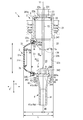
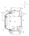
- the dispenser 1 As shown in FIGS. 1 to 3, the dispenser 1 according to the first embodiment of the present invention includes a cap portion 2, a pump portion 3, and a nozzle portion 4. 1 and 2 show a state of the dispenser 1 before the discharge operation. 5 and 6 show a state after the start of the discharge operation of the dispenser 1, FIG. 5 shows a state immediately after the start of the operation, and FIG. 6 shows a state after the discharge operation.
- the state before the discharge operation is a state before the discharge operation is performed on the dispenser 1
- the state after the discharge operation is a state after the discharge operation is performed on the dispenser 1.
- FIG. 3 is an exploded view illustrating the configuration of the dispenser 1.
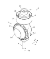
- the pump unit 3 includes a lid 31 and a casing 32 having a recess 39 inside and serving as a main body to which the lid 31 is mounted.
- the pump portion 3 is formed as a pump chamber 30 by the lid 31 and the casing 32.
- the casing 32 is made of resin and has a substantially bottomed cylindrical shape.
- the casing 32 has an opening 33 formed on one end surface 32a in the axial direction X.
- the axial direction X coincides with the pressurizing direction when the discharge operation is performed
- the diametrical direction Y is the lid 31 and the pump portion 3 when the pump portion 3 is viewed from the lid 31 side. Corresponds to the radial direction.
- the casing 32 is formed with a flow path having a circular cross section that penetrates the pump portion 3 in the radial direction Y, which is a direction orthogonal to the axial direction X.
- One end side of the flow path forms a suction path 341, and the other end side of the flow path forms a discharge path 342.
- the suction passage 341 and the discharge passage 342 each communicate with the pump chamber 30.
- a cap portion 2 is attached to the outer periphery of the suction path 341.
- the cap portion 2 includes three cylindrical portions 21, 22, and 23 having the same center and different diameters.
- the cylindrical portion 21 has a screw formed on the inner peripheral side thereof, and as shown in FIG.
- the cylindrical portion 21 is rotated with respect to the mouth neck 101 of the liquid storage container 100 formed of the film material, thereby causing the mouth neck 101. It constitutes a mounting portion for mounting the dispenser 1 on the liquid storage container 100 by screwing into.
- the cylindrical portion 22 has a cap portion 2 and a pump portion 3 integrated by inserting the outer periphery of the suction path 341 into the cylindrical portion 22 and welding the suction path 341 by a laser or the like.
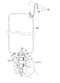
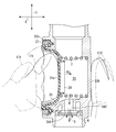
- the liquid storage container 100 is an inverted type used by being suspended from a towel hanger 160, for example, by a hook 150.
- the nozzle portion 4 is located downward, and the liquid G1 stored in the container is sucked from the inside of the liquid storage container 100 located above the pump. There is.
- the dispenser 1 is subjected to a discharge operation of picking with the fingers 170 of the user's hand [for example, thumb 171 and index finger 172], a constant amount of liquid G in the pump chamber 30 is discharged from the nozzle portion 4, and when the discharge operation is released, the liquid is discharged.
- the liquid G1 is sucked into the pump chamber 30 from the storage container 100.
- the end surface 32b constitutes a pressing support portion arranged to face the lid body 31, and the top portion and the end surface 32b of the lid body 31 are pressed from the side of the casing 32 with fingers 171 and 172. It can be picked up with and discharged.
- the end surface 32b serving as the pressing support portion is formed as a flat surface.
- the cylindrical portion 23 is a portion that is inserted into the mouth neck 101 and is located in the liquid storage container 100 when the dispenser 1 is attached to the liquid storage container 100, and as shown in FIGS. 1 and 3, the cylindrical portion 23 is a portion that is inserted into the mouth and neck portion 101.
- the inside thereof is a liquid inflow path 231.
- the wall portion 22a formed at the boundary between the cylindrical portion 22 and the cylindrical portion 23 is formed with a suction port 232 that communicates with the liquid inflow passage 231 and the suction passage 341.
- a suction valve 5 is provided inside the cylindrical portion 22.
- the suction valve 5 includes a valve body that opens and closes the suction port 232 and a support portion that supports the valve body at intervals in the circumferential direction, and is formed between the inner end surface 22b of the wall portion 22a and the end surface 341a of the suction path 341. It is installed in the space. That is, the suction valve 5 is held in a state of being sandwiched from both sides by the cap portion 2 and the pump portion 3.
- the suction valve 5 is a resin molded product.
- the suction valve 5 is formed so as to close when the internal pressure of the pump chamber 30 becomes high, shield the suction port 232, and stop the flow of liquid from the liquid storage container 100 into the pump chamber 30.
- the suction valve 5 is formed so as to open the suction port 232 when the internal pressure of the pump chamber 30 becomes low and suck the liquid G1 from the inside of the liquid storage container 100.
- the discharge path 342 located on the opposite side of the suction path 341 is formed so as to communicate with the tubular nozzle mounting portion 343.
- the nozzle portion 4 is mounted on the nozzle mounting portion 343.
- the nozzle portion 4 includes an in-nozzle flow path 41 formed so as to penetrate the inside of the nozzle portion, and a mounting flange 42 for mounting on the nozzle mounting portion 343.
- a discharge port 46 is formed at one end 41a [nozzle tip 4a] of the flow path 41 in the nozzle.
- the other end 41b of the in-nozzle flow path 41 is formed so as to communicate with the discharge port 344 formed at the end of the discharge path 342.
- the mounting flange 42 is formed with an annular groove 43 having a stepped portion 44 inside.
- a tubular nozzle mounting portion 343 is inserted into the groove 43.
- a convex portion 45 that engages with the step portion 44 is formed on the outer peripheral surface of the nozzle mounting portion 343.
- the dispenser 1 is formed so that the nozzle mounting portion 343 is inserted into the groove 43 and the stepped portion 44 and the convex portion 45 are engaged with each other to prevent the nozzle portion 4 from coming off.
- a discharge valve 6 is arranged inside the nozzle mounting portion 343.
- the discharge valve 6 includes a valve body that opens and closes the discharge port 344 and a support portion that supports the valve body at intervals in the circumferential direction, and is between the end portion 4b of the nozzle portion 4 and the inner end surface 343a of the nozzle mounting portion 343. It is arranged in the space formed in. That is, the discharge valve 6 is held in a state of being sandwiched from both sides by the nozzle portion 4 and the pump portion 3.
- the discharge valve 6 is a resin molded product.
- the discharge valve 6 opens when the internal pressure of the pump chamber 30 increases to open the discharge port 344, and discharges the liquid in the pump chamber 30 from the discharge port 46 to the outside via the flow path 41 in the nozzle.
- the discharge valve 6 is formed so as to close the valve when the internal pressure of the pump chamber 30 becomes low to close the discharge port 344 and stop the flow of liquid from the inside of the pump chamber 30 to the flow path 41 in the nozzle.
- the liquid inflow path 231 and the suction port 232, the suction path 341, the discharge path 342, the discharge port 344, and the in-nozzle flow path 41 [nozzle portion 4] are in series so that their centers are located on the same straight line. It is arranged in. In the present embodiment, this straight line is the center line Y1 of the nozzle orthogonal to the discharge operation direction Xb to the lid 31. That is, as shown in FIG. 1, the suction passage 341 and the discharge passage 342 are arranged to face each other via the pump chamber 30.
- the lid 31 is attached to the casing 32 so as to cover the opening 33 of the casing 32.
- the lid 31 is made of a material that can be elastically deformed.
- the lid 31 has a top surface 31a located on the opposite side of the end face 32b and is formed in a substantially flat prefix conical shape, and has a top surface 31a as a flat surface at the top.
- the top surface 31a and the end surface 32b of the lid 31 are formed as planes parallel to each other.
- the lid 31 is inflated in a direction (hereinafter referred to as “restoration direction Xa”) protruding outward from the casing 32 indicated by an arrow Xa.
- the lid 31 presses and deforms the liquid G in the pump chamber 30 toward the inside of the pump chamber 30, for example, with a human finger 170 (see FIG. 4), thereby causing the liquid G in the pump chamber 30 to be deformed. Discharge from the discharge port 46.
- the direction indicated by the arrow Xb pressed during the discharge operation is hereinafter referred to as "discharge operation direction Xb". Then, when the discharge operation is released, the lid 31 is restored in the restoration direction Xa, and the liquid G is sucked into the pump chamber 30 from the liquid storage container 100.
- an annular flange portion 31c protruding in the radial direction Y is formed on the opening side 31b of the lid 31 located on the opposite side of the top surface 31a.
- the flange portion 31c is inserted from the opening 33 side into a circular mounting groove 345 formed on the end surface 32a of the casing 32 concentrically with the opening 33.
- the flange portion 3c is formed with a lip portion 36 that can be inserted into the slit portion 346 formed in the bottom portion 345c of the mounting groove 345.
- the flange portion 31c and the mounting groove 345 are formed so that the lip portion 36 is inserted into the slit portion 346 when the flange portion 31c is mounted in the mounting groove 345. Therefore, as shown in FIG. 1, the dispenser 1 is configured such that the lip portion 36 occupies the engaged state due to insertion into the slit portion 346 to prevent the lid 31 from rotating in the circumferential direction. ing.
- a ring shape is formed between the annular outer inner wall 345a of the mounting groove 345 and the outer surface 31d of the lid 31 facing the outer inner wall 345a when mounted in the mounting groove 345.
- the stopper member 37 of the above is mounted so as to be in the fitted state.
- the flange portion 31c of the lid 31c is pressed against the outer inner wall 345a, the inner inner wall 345b, and the bottom portion 345c of the mounting groove 345. Therefore, the lid 31 is mounted on the casing 32 so as not to come off from the annular mounting groove 345 even when pressed in the discharge operation direction Xb.
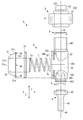
- the dispenser 1 includes a coil spring 7 in the pump portion 3 (pump chamber 30) that urges the lid 31 toward the restoration direction Xa, which is the outside of the casing 32. ..
- the coil spring 7 is a compression coil spring, and as shown in FIG. 1, one end 7a side thereof is mounted on the bottom surface 32e of the casing 32, and the other end 7b side is mounted on a spring receiving portion 38 formed on the inner surface 31e of the lid 31.
- the spring receiving portion 38 includes an annular rib 38a protruding from the inner surface 31e of the lid 31 toward the inside of the pump chamber 30.
- the bottom surface 32e with which the coil spring 7 is in contact and the end surface 32b serving as the pressing support portion are in a positional relationship opposite to each other. Therefore, when the top portion 31a and the end surface 32b of the lid 31 are picked up by the fingers 170 from the side side of the casing 32 and discharged, the force of the fingers is surely transmitted to the coil spring 7.
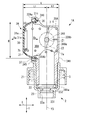
- the length L of the dispenser 1 from the lid 31 to the end face 32b serving as the pressing support portion is defined. That is, when the virtual plane Y2 that passes through the center line Y1 of the nozzle orthogonal to the discharge operation direction Xb and is perpendicular to the discharge operation direction Xb is used as a reference, the top surface of the lid 31 before deformation is obtained from this virtual plane Y2.
- the length to 31a is L1 and the distance from the virtual plane Y2 to the end face 32b is L2
- the distance L from the top surface 31a to the end face 32b is L1 + L2.
- the distance L is a distance at which it is easy to pinch the top portion 31a and the end surface 32b of the lid 31 with two or three fingers 170 of one hand.
- the distance L1 is set longer than the distance L2. This is to secure a stroke amount in which the lid 31 sufficiently enters the pump chamber 30 and deforms when the lid 31 is discharged. Further, it is preferable that the distance L1 is not too large with respect to the distance L2 from the viewpoint of enabling more stable discharge operation.
- the distance L1 is preferably 3 times or less of the distance L2, and the distance is preferably 3 times or less. It is more preferably 2.5 times or less of L2.
- the material used for the casing 32 is a material having a higher rigidity than the material used for the lid 31, and the casing 32 bends before the lid 31 when the discharge operation is performed on the lid 31. It is formed so that it never happens.
- the virtual plane Y2 is described with an exaggerated angle in consideration of legibility.
- the dispenser 1 according to the present embodiment can perform a discharge operation by pinching the top surface 31a and the end surface 32b of the lid 31 with fingers. More specifically, in the dispenser 1 according to the present embodiment, as shown in FIG. 4, after mounting on the liquid storage container 100, as shown in FIG. 5, for example, the thumb 171 is attached to the top surface 31a of the lid 31. The abdomen is applied, the abdomen of the index finger 172 or the middle finger is applied to the end surface 32b of the casing 32, and the pump portion 3 is pinched and held from the lateral axial direction X. From this state, the user presses and pushes the lid 31 in the discharge operation direction Xb against the repulsive force of the coil spring 7.
- the lid 31 begins to be partially deformed toward the inside of the pump chamber 30 by applying a pressing force to the top surface 31a of the lid 31. Therefore, the user can firmly hold the top surface 31a and the end surface 32b with his / her fingers at the initial stage of the discharge operation.
- the lid 31 When the lid 31 is further pushed in the discharge operation direction Xb while being held, the lid 31 is greatly bent into the pump chamber 30 as shown in FIG. Then, the volume of the pump chamber 30 is reduced, the chamber pressure is increased, the flow of the liquid from the suction port 232 is stopped by the suction valve 5, the discharge valve 6 is opened, the discharge port 344 is opened, and the pump chamber is opened.
- the liquid G in 30 is quantitatively discharged from the discharge port 46 via the flow path 41 in the nozzle.
- the lid body 31 moves toward the restoration direction Xa due to the repulsive force of the coil spring 7, and before deformation. It changes to restore the original shape of. Therefore, since the internal pressure of the pump unit 3 becomes low, the discharge valve 6 is closed to close the discharge port 344, and the suction valve 5 is opened to open the suction port 232 to enter the liquid storage container 100. A certain amount of the liquid G1 is sucked into the pump unit 3 through the suction port 232 and the suction path 341.
- the pressing support portion arranged to face the lid body 31 is provided, and the top portion (top surface 31a) of the lid body 31 and the end surface 32b serving as the pressing support portion are lateral to the casing 32.
- the discharge operation can be performed by picking it with a finger 170 from the side. Therefore, the position of the finger 170 is less likely to shift during the discharge operation, and the discharge operation of pushing the lid 31 into the pump chamber 30 can be easily and stably performed.
- the two fingers of one hand may be moved from the direction intersecting the axial direction X so as to face each of the top surface (top surface 31a) of the lid 31 and the end surface 32b serving as the pressing support portion. It is possible.
- the direction in which pressure is applied to the top portion (top surface 31a) of the lid 31 and the end surface 32b serving as the pressing support portion by pinching with two fingers is the direction along the above-mentioned axial direction X, which is the lateral side of the casing 32.
- the top (top surface 31a) of the lid 31 and the end surface 32b serving as the pressing support portion face each other in the horizontal direction when the dispenser 1 is mounted on the liquid storage container 100 in an upright or inverted state. It is preferable to be arranged in.
- the dispenser 1 is a small dispenser assuming that the amount of liquid discharged by one discharge operation is about several milliliters.
- the diameter R of the lid 31 is 23.27 mm
- L1 is 14.85 mm
- L2 is 7.85 mm.
- the diameter R of the lid 31 is the distance between the outer surfaces 31d of the opposing portions of the lid 31 when mounted on the casing 32.
- the material used for the lid 31 include elastomer, silicon, and NBR.
- Examples of the material used for the casing 32 include resin materials such as PP (polypropylene) and PE (polyethylene).
- the distance L is preferably 5 mm or more, more preferably 10 mm or more, and preferably 40 mm or less, more preferably 30 mm. It is less than or equal to, preferably 5 mm or more and 40 mm or less, and more preferably 10 mm or more and 30 mm or less.
- the dispenser 1A according to the second embodiment of the present invention will be described with reference to FIGS. 7 to 11.
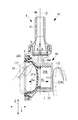
- the dispenser 1A according to the second embodiment includes a cap portion 2, a pump portion 3A, and a nozzle portion 4 as shown in FIGS. 7, 8 and 9.
- these members are mounted on a casing 32A in which the cap portion 2 and the nozzle portion 4 are arranged in a direction orthogonal to the pump portion 3A and constitute the pump portion 3A. As shown in FIG.
- the dispenser 1A is screwed into the mouth and neck 101 by rotating the cylindrical portion 21 of the cap 2 with respect to the mouth and neck 101 formed on the upper part of the self-supporting liquid storage container 100A. Then, it is attached to the upper part of the liquid storage container 100A and used.
- the dispenser 1A has a lid 31 mounted so as to cover the opening 33 formed in the upper part of the casing 32A.
- the pump portion 3A forms a space surrounded by the lid 31 and the casing 32A as the pump chamber 30A.
- the dispenser 1A picks the lid 31 and the end surface 32Ab serving as the pressing support portion of the casing 32A with fingers 170 (see FIG.
- the dispenser 1A is a so-called pump dispenser in which a liquid is sucked into the pump chamber 30A from the liquid storage container 100A by releasing the pinched finger 170 to release the discharge operation, as shown in FIG.
- the discharge operation is an operation in which the user picks the lid 31 and the end surface 32Ab of the pump portion 3A with the fingers 170 of the hand and pushes the lid 31 to the left.
- the difference between the pump unit 3 and the pump unit 3A is the shape of the casing 32A.
- a suction path 341 is formed below the tubular casing 32A with the end surface 341a facing downward.
- the casing 32A is formed so that the discharge path 342 extends in the discharge direction Z orthogonal to the discharge operation direction X. That is, the casing 32A has an L-shaped cross section.
- the cap portion 2 is integrated with the pump portion 3A by inserting the suction path 341 into the cylindrical portion 22.
- a pumping pipe 180 inserted into the liquid storage container 100A is connected to the cylindrical portion 23, and when the dispenser 1A is mounted on the liquid storage container 100A, the liquid in the container is discharged from below the container. It is said that it can be pumped up.
- the suction port 232 formed in the wall portion 22a at the boundary between the cylindrical portion 22 and the cylindrical portion 23 communicates with the liquid inflow passage 231 extending in the radial direction Y and the suction passage 341, and is cylindrical. It is opened and closed by a suction valve 5 arranged between the portion 22 and the suction passage 341.
- the discharge path 342 extending in the discharge direction Z is formed so as to communicate with the in-nozzle flow path 41 of the nozzle portion 4 mounted on the nozzle mounting portion 343 via the discharge port 344.
- a discharge valve 6 for opening and closing the discharge port 344 is arranged between the discharge path 342 and the nozzle portion 4.
- the dispenser 1A is arranged so that the liquid inflow path 231, the suction port 232, the suction valve 5, and the suction path 341 are located on the center line Y3 extending in the radial direction Y and passing through the pump chamber 30A. ing.
- the dispenser 1A is arranged such that the discharge path 342, the discharge valve 6, and the flow path 41 in the nozzle are located on the center line Z1 of the nozzle extending in the discharge direction Z.
- the end surface 32Ab is formed as a flat surface.
- the center line Y3 and the center line Z1 are arranged so as to face the lid body 31, and together with the lid body 31, an end face constituting a pressing support portion that can be picked up from the side of the casing 32A with a finger 170 and discharged. It is orthogonal to 32Ab.
- the center line Y3 and the center line Z1 pass through the pump chamber 30A and have the same distance from the end face 32Ab.
- the lid 31 is made of an elastically deformable material as in the first embodiment, and is inflated from the casing 32A in the restoration direction Xa before the discharge operation (before deformation). As shown in FIGS. 10 and 11, the lid 31 is subjected to a discharge operation in which the liquid in the pump chamber 30A is deformed by pressing with a human finger 170 toward the discharge operation direction Xb, so that the liquid in the pump chamber 30A is discharged from the nozzle portion 4. It is discharged from the discharge port 46 to the outside. When the pinching finger 170 is released and the discharge operation is released, the lid 31 pumps the liquid G1 from the liquid storage container 100A into the pump chamber 30A and flows it into the pump chamber 30A, as shown in FIGS. 9 and 11.
- the flange portion 31c formed on the opening side 31b of the lid 31 is inserted from the opening 33 side into a circular mounting groove 345 formed in the casing 32A concentrically with the opening 33.
- the lid 31 has an annular mounting groove even when pressed in the discharge operation direction Xb by mounting the ring-shaped stopping member 37 on the mounting groove 345 with the flange portion 31c inserted in the mounting groove 345. It is fixed to the casing 32A so as not to come off from the 345.
- a lip portion 36 and a slit portion 346 are formed in the flange portion 3c and the mounting groove 345, respectively, as in the first embodiment.
- the dispenser 1A includes a coil spring 7 that urges the lid 31 in the pump portion 3A (pump chamber 30A) toward the restoration direction Xa, which is the outside of the casing 32A.
- One end 7a side of the coil spring 7 is mounted on the bottom surface 32Ae of the casing 32A, and the other end 7b side is engaged with a spring receiving portion 38 formed on the inner surface 31e of the lid 31.
- the length La from the lid 31 to the end face 32Ab serving as the pressing support portion is specified. That is, when the virtual plane Z2 passing through the center line Z1 of the nozzle orthogonal to the discharge operation direction Xb and perpendicular to the discharge operation direction Xb is used as a reference, the top surface 31a which is the top of the lid 31 before deformation from the virtual plane Z2.
- the distance La from the top surface 31a to the end face 32Ab is L1 + L2.
- the distance La is a distance at which the top surface 31a and the end surface 32Ab of the lid 31 can be pinched with two or three fingers 170 of one hand.
- the distance L1 is set longer than the distance L2. This is to secure a stroke amount in which the lid 31 sufficiently enters the pump chamber 30A and deforms when the lid 31 is discharged.
- the material used for the casing 32A is a material having a higher rigidity than the material used for the lid 31, and the casing 32A bends before the lid 31 when the discharge operation is performed on the lid 31. It is formed so that it never happens.
- the virtual plane Z2 is shown with an exaggerated angle in consideration of legibility.
- the belly of the thumb 171 is placed on the top surface 31a of the lid 31, and the index finger 172 or the middle finger is placed.
- the antinode of the casing 32A is brought into contact with the end surface 32Ab of the casing 32A, and the pump portion 3A is pinched and held from the axial direction X. From this state, the user presses and pushes the lid 31 in the discharge operation direction Xb against the repulsive force of the coil spring 7.
- the lid 31 begins to be partially deformed toward the inside of the pump chamber 30A by applying a pressing force to the top surface 31a. Therefore, the user can firmly hold the top surface 31a and the end surface 32Ab with his / her fingers at the initial stage of the discharge operation.
- the lid 31 When the lid 31 is further pushed in the discharge operation direction Xb while being held, the lid 31 is greatly bent into the pump chamber 30A. Then, the volume of the pump chamber 30A is reduced, the chamber pressure is increased, the flow of the liquid from the suction port 232 is stopped by the suction valve 5, the discharge valve 6 is opened, the discharge port 344 is opened, and the pump chamber is opened.
- the liquid G in 30A is quantitatively discharged from the discharge port 46 via the flow path 41 in the nozzle.
- the dispenser 1A is provided with an end surface 32Ab which is arranged to face the lid 31 and serves as a pressing support portion which can be pinched with fingers from the side of the casing 32A together with the lid 31 to perform a discharge operation. Therefore, the lid 31 and the end surface 32Ab can be pinched together with fingers 170 from the side side of the casing 32A (the axial direction X intersecting in the same plane as the radial direction Y) to enable the discharge operation. Therefore, since the position shift of the finger 170 during the discharge operation is eliminated, the discharge operation of deforming the lid 31 into the pump chamber 30A is stable, and the dispenser 1A capable of performing a good discharge operation can be provided.
- the length from the virtual plane Z2 to the top surface 31a of the lid 31 is L1 and the length from the virtual plane Z2 to the pressing support portion with reference to the virtual plane Z2 passing through the center line Z1 of the nozzle orthogonal to the discharge operation direction Xb to the lid 31.
- L1 the distance to the end surface 32Ab
- L1> L2 it is easy to secure the stroke amount (deformation amount) of the lid 31 into the pump chamber 30A, and the liquid is discharged at the target discharge amount. It is possible to provide a dispenser 1A capable of performing a good discharge operation.
- the diameter R, the distance L1 and the distance L2 of the lid 31 are set as in the dispenser 1, and the material used for the lid 31 is the same.
- the dispenser 1A is a small dispenser assuming that the amount of liquid discharged by one discharge operation is about several milliliters.
- the diameter R of the lid 31 is 23.27 mm
- L1 is 14.85 mm
- L2 is 7.85 mm.
- the diameter R of the lid 31 is the distance between the outer surfaces 31d of the opposing portions of the lid 31 when mounted on the casing 32A. According to the configuration of the dispenser 1A provided with the lid 31 of such dimensions and materials, when the lid 31 is sandwiched between fingers and pressed in the discharge operation direction Xb, there is no misalignment of the fingers and the lid 31 is satisfactorily used. Was able to perform the discharge operation.
- the dispensers 1 and 1A the end surfaces 32b and 32Ab of the casing located on the opposite side of the lid 31 are used as flat surfaces to form the pressing support portion, but the dispensers 1 and 1A may be substantially flat surfaces. That is, it may have a curved surface as long as it is larger than the radius of curvature of the discharge port 344. Further, in the dispensers 1 and 1A, an uneven portion extending in the diameter direction Y may be formed on the end faces 32b and 32Ab to serve as a pressing support portion.
- the end faces 32b and 32Ab may be used as a pressing support portion as a curved surface recessed toward the pump chambers 30 and 30A. It is preferable to form the pressing support portion as such a concavo-convex portion or a curved surface because it is difficult to slip when picked with a finger 170 and can be firmly held.
- a pump chamber is formed by a main body having a recess and a lid covering an opening of the main body, and a discharge operation of pressing the lid toward the pump chamber to deform it causes liquid in the pump chamber to be discharged.
- a dispenser that discharges liquid from the nozzle portion and releases the discharge operation to allow liquid to flow into the pump chamber.
- a dispenser having a pressing support portion arranged to face the lid body, and the top portion of the lid body and the pressing support portion are picked up from the side of the main body by a finger to perform a discharge operation.
- ⁇ 2> The dispenser according to ⁇ 1>, wherein the distance from the pressing support portion to the top of the lid is 5 mm or more and less than 30 mm.
- the distance from the virtual plane to the top of the lid is L1 with reference to a virtual plane that passes through the center line of the nozzle and is perpendicular to the discharge operation direction, which is the pressing direction of the lid when the discharge operation is performed.
- ⁇ 4> The dispenser according to any one of ⁇ 1> to ⁇ 3>, wherein the lid body is inflated on the side opposite to the main body and has a substantially flat top surface.
- ⁇ 5> The dispenser according to any one of ⁇ 1> to ⁇ 4>, wherein the pressing support portion has a substantially flat surface.
- ⁇ 6> The dispenser according to any one of ⁇ 1> to ⁇ 4>, wherein the top surface of the lid and the end surface serving as the pressing support portion are arranged so as to face each other in the horizontal direction.
- a coil spring for urging the lid body outward is provided in the pump chamber.
- ⁇ 8> The dispenser according to ⁇ 7>, wherein one end side of the coil spring is placed on the bottom surface of the recess and the other end side is in contact with the inner surface 31e of the lid body.
- ⁇ 9> The dispenser according to ⁇ 8>, wherein the bottom surface with which the coil spring is in contact and the pressing support portion face each other.
- the main body has a suction path as a flow path for the liquid flowing into the pump chamber and a discharge path as a flow path for the liquid discharged from the nozzle portion, and each of the suction path and the discharge path has the pump chamber.
- ⁇ 11> The dispenser according to ⁇ 10>, wherein the suction passage and the centers of the discharge passages are arranged in series so as to be located on the same straight line.
- ⁇ 12> The dispenser according to ⁇ 10>, wherein the suction passage and the discharge passage are arranged so as to face each other via the pump chamber.
- the position of the finger is less likely to shift during the discharge operation, and the discharge operation of pushing the lid into the pump chamber can be easily and stably performed.
Abstract
La présente invention concerne un distributeur (1) qui forme une chambre de pompe (30) dotée d'un corps (32) présentant une partie évidée (39) et un corps de couvercle (31) recouvrant une partie d'ouverture (33) du corps, réalise une opération d'éjection pour presser et déformer le corps de couvercle en direction de l'intérieur de la chambre de pompe pour éjecter un liquide à l'intérieur de la chambre de pompe à partir d'une partie de buse (4) et annule l'opération d'éjection pour amener le liquide à s'écouler dans la chambre de pompe (30). Le distributeur (1) est doté d'une partie de support de presse (32b) qui est agencée en regard du corps de couvercle (31). L'opération d'éjection est réalisée de sorte qu'une partie supérieure (31a) du corps de couvercle et la partie de support de presse (32b) sont collectées par des doigts à partir d'un côté latéral du corps (32).
Priority Applications (4)
| Application Number | Priority Date | Filing Date | Title |
|---|---|---|---|
| JP2021548374A JPWO2021059697A1 (fr) | 2019-09-25 | 2020-07-17 | |
| EP20867276.6A EP4036032A4 (fr) | 2019-09-25 | 2020-07-17 | Distributeur |
| CN202080067012.XA CN114521187A (zh) | 2019-09-25 | 2020-07-17 | 分配器 |
| US17/762,660 US20220331823A1 (en) | 2019-09-25 | 2020-07-17 | Dispenser |
Applications Claiming Priority (2)
| Application Number | Priority Date | Filing Date | Title |
|---|---|---|---|
| JP2019-174810 | 2019-09-25 | ||
| JP2019174810 | 2019-09-25 |
Publications (1)
| Publication Number | Publication Date |
|---|---|
| WO2021059697A1 true WO2021059697A1 (fr) | 2021-04-01 |
Family
ID=75166546
Family Applications (1)
| Application Number | Title | Priority Date | Filing Date |
|---|---|---|---|
| PCT/JP2020/027976 WO2021059697A1 (fr) | 2019-09-25 | 2020-07-17 | Distributeur |
Country Status (6)
| Country | Link |
|---|---|
| US (1) | US20220331823A1 (fr) |
| EP (1) | EP4036032A4 (fr) |
| JP (1) | JPWO2021059697A1 (fr) |
| CN (1) | CN114521187A (fr) |
| TW (1) | TW202124228A (fr) |
| WO (1) | WO2021059697A1 (fr) |
Citations (6)
| Publication number | Priority date | Publication date | Assignee | Title |
|---|---|---|---|---|
| US2071977A (en) | 1935-10-10 | 1937-02-23 | Fairbanks Morse & Co | Coil winding for dynamo-electric machines |
| JPH0692383A (ja) * | 1992-07-10 | 1994-04-05 | Hayakawa Sanki Kk | 出入り口共用のベローズ付き軟性容器と出入り口共用のベローズ型ポンプ動作機構の液体・粉体定量抽出ディスペンサー |
| JP2001180728A (ja) * | 1999-12-27 | 2001-07-03 | Kiyota Engineering:Kk | 飲料容器用注出装置 |
| US20060049208A1 (en) * | 2004-09-09 | 2006-03-09 | Daansen Warren S | Slit valves and dispensing nozzles employing same |
| JP2007509827A (ja) * | 2003-10-28 | 2007-04-19 | シークイスト クロージャーズ フォーリン、 インコーポレイテッド | 流体小出し部材 |
| JP2012522184A (ja) * | 2009-03-30 | 2012-09-20 | ミードウエストベコ・カルマー・ネザーランド・べー・ヴェー | ポンプデバイスおよびその製造方法 |
Family Cites Families (45)
| Publication number | Priority date | Publication date | Assignee | Title |
|---|---|---|---|---|
| US2772817A (en) * | 1952-03-01 | 1956-12-04 | Robert J Jauch | Dispensing pumps |
| US2709025A (en) * | 1953-03-30 | 1955-05-24 | Scott Thomas Willard | Dispenser for measured quantity of paste |
| US2888034A (en) * | 1956-08-02 | 1959-05-26 | Glegg Douglas | One-piece double check valve |
| US3162333A (en) * | 1959-07-30 | 1964-12-22 | Guild Molders | Multiple-part plastic pump for liquids |
| US3160329A (en) * | 1963-02-26 | 1964-12-08 | Radic Frank | Dispensing device |
| US3220611A (en) * | 1964-08-14 | 1965-11-30 | Waldo H Zander | Wall mounted bracket and dispenser for collapsible tube |
| US3485419A (en) * | 1968-01-30 | 1969-12-23 | Wilfred V Taylor | Fluent material dispenser |
| US3952924A (en) * | 1968-11-08 | 1976-04-27 | Gustav Eric Valdemar Benson | Dispenser for dispensing a liquid or pasty product from a container |
| SE333624B (fr) * | 1969-07-28 | 1971-03-22 | Perpedos Ab | |
| US3987938A (en) * | 1975-09-18 | 1976-10-26 | Diamond International Corporation | Dispensing pump |
| GB2062771B (en) * | 1979-10-15 | 1983-06-29 | Tranas Rostfria Ab | Dispensing device |
| ATE49716T1 (de) * | 1985-01-28 | 1990-02-15 | Earl Wright Co | Schaumerzeuger. |
| US5076322A (en) * | 1990-10-15 | 1991-12-31 | Pradip Choksi | Vacuum limiting, regulating device |
| US6092695A (en) * | 1992-05-11 | 2000-07-25 | Cytologix Corporation | Interchangeable liquid dispensing cartridge pump |
| US5356038A (en) * | 1993-01-21 | 1994-10-18 | Sprintvest Corporation N.V. | Wall mountable cream tube dispenser |
| DE69417731T2 (de) * | 1993-02-10 | 1999-10-07 | Reilly Daniel Joseph O | Beutel zum spenden von fliessfähigen materialien |
| US5390822A (en) * | 1993-07-26 | 1995-02-21 | Merck & Co., Inc. | Packaging vial for a liquid product in particular medicinal or cosmetic |
| DE19544693C2 (de) * | 1995-11-30 | 1998-11-19 | Dental Kosmetik Gmbh Dresden | Verschluß zur portionierten Abgabe von liquidem Füllgut aus Behältern |
| US6158620A (en) * | 1999-02-11 | 2000-12-12 | Chester Labs, Inc. | Collapsible container |
| DE50113369D1 (de) * | 2000-12-15 | 2008-01-24 | Medisize Schweiz Ag | Spenderausguss für fliessfähige Medien |
| US7501283B2 (en) * | 2003-08-11 | 2009-03-10 | Sakura Finetek U.S.A., Inc. | Fluid dispensing apparatus |
| KR200347812Y1 (ko) * | 2003-12-08 | 2004-04-17 | 강성일 | 화장품 정량 토출 사용이 가능한 화장품용기 구조 |
| US8899449B2 (en) * | 2004-09-09 | 2014-12-02 | Warren S. Daansen | Nozzle tip with slit valve for fluid dispenser |
| US7434710B2 (en) * | 2005-11-23 | 2008-10-14 | Joseph S. Kanfer | Bellows pump mechanism |
| US8459509B2 (en) * | 2006-05-25 | 2013-06-11 | Sakura Finetek U.S.A., Inc. | Fluid dispensing apparatus |
| CN2937092Y (zh) * | 2006-08-02 | 2007-08-22 | 袁建军 | 一种新型液体分配器 |
| US20080156829A1 (en) * | 2006-12-28 | 2008-07-03 | Jan-Sun Chen | Structure for controlling soap discharging quantity of soap dispensing apparatus |
| US8579159B2 (en) * | 2008-01-18 | 2013-11-12 | Gojo Industries, Inc. | Squeeze action foam pump |
| ES2356802T3 (es) * | 2008-05-28 | 2011-04-13 | Gojo Industries, Inc. | Pistón de aire bomba de espuma de tipo bóveda. |
| DE102008030203B4 (de) * | 2008-06-25 | 2016-12-08 | Mahle International Gmbh | Druckregelventil |
| US9283582B2 (en) * | 2009-03-30 | 2016-03-15 | Meadwestvaco Calmar Netherlands B.V. | Pouch and pump dispensing system |
| US10226783B2 (en) * | 2009-03-30 | 2019-03-12 | Silgan Dispensing Systems R&D Netherlands B.V. | Pump device and methods for making the same |
| US8353428B2 (en) * | 2009-07-21 | 2013-01-15 | Fres-Co System Usa, Inc. | Volumetric metering fitment and package including the same |
| JP5302176B2 (ja) * | 2009-12-16 | 2013-10-02 | 多田プラスチック工業株式会社 | 流体用ダイヤフラムポンプ |
| US9072411B2 (en) * | 2013-03-14 | 2015-07-07 | Gojo Industries, Inc. | Air-vented liquid dispensers and refill units therefor |
| WO2017091091A1 (fr) * | 2015-11-25 | 2017-06-01 | Iwanejko Electronics Zdzisław Iwanejko | Dispositif de distribution pour la distribution de liquides à partir d'un emballage souple pour liquides |
| ITUB20159355A1 (it) * | 2015-12-23 | 2017-06-23 | Taplast Srl | Dispositivo per l?erogazione di fluidi o miscele |
| DE102017010071A1 (de) * | 2016-11-02 | 2018-05-03 | Mann+Hummel Gmbh | Einheit zum Regeln oder Steuern eines Fluiddrucks |
| DE102016013009A1 (de) * | 2016-11-02 | 2018-05-03 | Mann + Hummel Gmbh | Einheit zum Regeln oder Steuern eines Fluiddrucks |
| DE102017010020A1 (de) * | 2016-11-02 | 2018-05-03 | Mann + Hummel Gmbh | Einheit zum Regeln oder Steuern eines Fluiddrucks |
| DE102017010019A1 (de) * | 2016-11-02 | 2018-05-03 | Mann + Hummel Gmbh | Einheit zum Regeln oder Steuern eines Fluiddrucks |
| DE102016013008A1 (de) * | 2016-11-02 | 2018-05-03 | Mann + Hummel Gmbh | Einheit zum Regeln oder Steuern eines Fluiddrucks |
| JP2020128234A (ja) * | 2019-02-08 | 2020-08-27 | 花王株式会社 | ディスペンサ |
| WO2020162483A1 (fr) * | 2019-02-08 | 2020-08-13 | 花王株式会社 | Distributeur et récipient de distribution |
| CN114521186A (zh) * | 2019-09-25 | 2022-05-20 | 花王株式会社 | 分配器 |
-
2020
- 2020-07-17 WO PCT/JP2020/027976 patent/WO2021059697A1/fr unknown
- 2020-07-17 JP JP2021548374A patent/JPWO2021059697A1/ja active Pending
- 2020-07-17 EP EP20867276.6A patent/EP4036032A4/fr active Pending
- 2020-07-17 US US17/762,660 patent/US20220331823A1/en active Pending
- 2020-07-17 CN CN202080067012.XA patent/CN114521187A/zh active Pending
- 2020-07-30 TW TW109125771A patent/TW202124228A/zh unknown
Patent Citations (6)
| Publication number | Priority date | Publication date | Assignee | Title |
|---|---|---|---|---|
| US2071977A (en) | 1935-10-10 | 1937-02-23 | Fairbanks Morse & Co | Coil winding for dynamo-electric machines |
| JPH0692383A (ja) * | 1992-07-10 | 1994-04-05 | Hayakawa Sanki Kk | 出入り口共用のベローズ付き軟性容器と出入り口共用のベローズ型ポンプ動作機構の液体・粉体定量抽出ディスペンサー |
| JP2001180728A (ja) * | 1999-12-27 | 2001-07-03 | Kiyota Engineering:Kk | 飲料容器用注出装置 |
| JP2007509827A (ja) * | 2003-10-28 | 2007-04-19 | シークイスト クロージャーズ フォーリン、 インコーポレイテッド | 流体小出し部材 |
| US20060049208A1 (en) * | 2004-09-09 | 2006-03-09 | Daansen Warren S | Slit valves and dispensing nozzles employing same |
| JP2012522184A (ja) * | 2009-03-30 | 2012-09-20 | ミードウエストベコ・カルマー・ネザーランド・べー・ヴェー | ポンプデバイスおよびその製造方法 |
Also Published As
| Publication number | Publication date |
|---|---|
| JPWO2021059697A1 (fr) | 2021-04-01 |
| TW202124228A (zh) | 2021-07-01 |
| US20220331823A1 (en) | 2022-10-20 |
| CN114521187A (zh) | 2022-05-20 |
| EP4036032A4 (fr) | 2023-10-18 |
| EP4036032A1 (fr) | 2022-08-03 |
Similar Documents
| Publication | Publication Date | Title |
|---|---|---|
| US11773840B2 (en) | Elastic member and pump assembly including the same | |
| JPH03148484A (ja) | 分与装置 | |
| EP3210672B1 (fr) | Pompe pour réceptacle, notamment un flacon de produit cosmétique, et dispositif de distribution comprenant une telle pompe | |
| JP6258128B2 (ja) | トリガー式液体噴出器 | |
| US11051660B2 (en) | Plastomer spring with captive valve | |
| JP7217362B2 (ja) | 医薬液体を放出するためのディスペンサー | |
| WO2021059696A1 (fr) | Distributeur | |
| US20160052662A1 (en) | Application system for small dose liquid, gel, serum or cream | |
| WO2021059697A1 (fr) | Distributeur | |
| US9833800B2 (en) | Vented pump | |
| EP3012029B1 (fr) | Dispositif destiné à contenir une substance fluide | |
| JP5820690B2 (ja) | 吐出ポンプ | |
| US20220097088A1 (en) | Dispenser and dispensing container | |
| US11154879B2 (en) | Orifice and spray container including the same | |
| KR20210146619A (ko) | 감도가 개선된 펌프식 액체 밀폐 용기 | |
| CN113747978A (zh) | 排出头和具有排出头的液体分配器 | |
| JP4573119B2 (ja) | 少量吐出容器 | |
| JPWO2021059697A5 (fr) | ||
| JP6422411B2 (ja) | ノズルヘッド | |
| EP2904931A1 (fr) | Récipient pour produit cosmétique de type crème | |
| JP7266962B2 (ja) | 吐出容器 | |
| JP6660830B2 (ja) | 定量吐出器 | |
| JP5554160B2 (ja) | 塗布具付き注出器 | |
| JP3217698U (ja) | スポイト | |
| KR101713048B1 (ko) | 액상 내용물의 정량 인출이 가능한 용기 |
Legal Events
| Date | Code | Title | Description |
|---|---|---|---|
| 121 | Ep: the epo has been informed by wipo that ep was designated in this application |
Ref document number: 20867276 Country of ref document: EP Kind code of ref document: A1 |
|
| ENP | Entry into the national phase |
Ref document number: 2021548374 Country of ref document: JP Kind code of ref document: A |
|
| NENP | Non-entry into the national phase |
Ref country code: DE |
|
| ENP | Entry into the national phase |
Ref document number: 2020867276 Country of ref document: EP Effective date: 20220425 |